US8334487B2 - Induction heating cooking device - Google Patents
Induction heating cooking device Download PDFInfo
- Publication number
- US8334487B2 US8334487B2 US12/278,696 US27869607A US8334487B2 US 8334487 B2 US8334487 B2 US 8334487B2 US 27869607 A US27869607 A US 27869607A US 8334487 B2 US8334487 B2 US 8334487B2
- Authority
- US
- United States
- Prior art keywords
- temperature
- heating
- infrared sensor
- cooking container
- cooking
- Prior art date
- Legal status (The legal status is an assumption and is not a legal conclusion. Google has not performed a legal analysis and makes no representation as to the accuracy of the status listed.)
- Active, expires
Links
Images


Classifications
-
- H—ELECTRICITY
- H05—ELECTRIC TECHNIQUES NOT OTHERWISE PROVIDED FOR
- H05B—ELECTRIC HEATING; ELECTRIC LIGHT SOURCES NOT OTHERWISE PROVIDED FOR; CIRCUIT ARRANGEMENTS FOR ELECTRIC LIGHT SOURCES, IN GENERAL
- H05B6/00—Heating by electric, magnetic or electromagnetic fields
- H05B6/02—Induction heating
- H05B6/06—Control, e.g. of temperature, of power
- H05B6/062—Control, e.g. of temperature, of power for cooking plates or the like
-
- H—ELECTRICITY
- H05—ELECTRIC TECHNIQUES NOT OTHERWISE PROVIDED FOR
- H05B—ELECTRIC HEATING; ELECTRIC LIGHT SOURCES NOT OTHERWISE PROVIDED FOR; CIRCUIT ARRANGEMENTS FOR ELECTRIC LIGHT SOURCES, IN GENERAL
- H05B2213/00—Aspects relating both to resistive heating and to induction heating, covered by H05B3/00 and H05B6/00
- H05B2213/07—Heating plates with temperature control means
Definitions
- the present invention relates to an induction heating cooking device for use in general homes, restaurants, offices and the like.
- induction heating cooking devices for induction-heating objects to be heated such as pans, using heating coils.
- Such induction heating cooking device is provided with a heat sensitive element such as a thermistor, on the lower surface of a top plate, so that the output of the heating coil is controlled based on the temperature of a pan which is detected through the top plate (hereinafter, referred to as a “detected temperature”), in order to prevent the occurrence of ignition of oil due to rises of the temperature of the oil within the pan.
- a heating cooking device of a patent document 1 compares a detected temperature with a control temperature which has been preliminarily set according to the output of a heating coil, and controls such that the output of the heating coil is reduced when the detected temperature exceeds the control temperature. Further, in order to prevent the ignition of oil without degrading the cooking performance, the value of the control temperature set preliminarily according to the output of the heating coil is changed according to the increase or decrease of the detected temperature, such that the value of the control temperature is set to 185 degrees C. and 203 degrees C. when the output of the heating coil is 2000 W and 1450 W, respectively.
- Patent Document 1 JP 2003-38347 A
- the present invention is intended for overcoming the conventional problems and aims at providing an induction heating cooking device capable of having increased detection sensitivity to the temperature of the bottom surface of a cooking container when this temperature is higher in cases of using a small amount of oil and, also, capable of preventing reduction of the heating output in cases of cooking at relatively lower temperatures such as in cases of cooking for boiled foods and oily fried foods.
- An induction heating cooking device includes: a top plate that is partially or entirely made of a material capable of transmitting infrared radiation, a cooking container being placed on the top plate; a heating coil that induction-heats the cooking container; an infrared sensor that detects infrared radiation which is emitted from a bottom surface of the cooking container faced to the heating coil and is passed through the top plate and that outputs a detection signal based on the quantity of energy of the detected infrared radiation; and a heating control section that controls supply of electric power to the heating coil by flowing a high-frequency electric current through the heating coil based on the temperature of the bottom surface of the cooking container which is detected by the detection signal; wherein, when the temperature of the bottom surface of the cooking container is equal to or higher than a first predetermined temperature which is higher than 230 degrees C., the infrared sensor outputs the detection signal having output values increasing as the bottom-surface temperature increases, and when the bottom-surface temperature is lower than the first predetermined temperature, the inf
- the induction heating cooking device may further include a temperature detection section that detects the temperature of the bottom surface of the cooking container, through a heat sensitive element which receives heat transferred from an underside surface of the top plate.
- the heating control section may control the supply of electric power to the heating coil based on the temperature of the bottom surface of the cooking container according to the infrared sensor, and when the infrared sensor is not outputting the detection signal, the heating control section may control the supply of electric power to the heating coil, such that the temperature of the bottom surface of the cooking container according to the temperature detection section is lower than a third predetermined temperature.
- the first predetermined temperature is, for example, 250 degrees C.
- the used oil temperature is at most 230 degrees C. and, therefore, the infrared sensor outputs no detection signal. This can prevent reduction of the heating output based on the detection signal from the infrared sensor, in cases of cooking for fried foods. Since the detection signal from the infrared sensor come up at 250 degrees C., it is possible to increase the detection sensitivity to higher temperatures equal to or higher than 250 degrees C., in cases of using a small amount of oil, such as in cases of cooking for sauteed foods generally at temperatures in the range of 200 to 300 degrees C.
- the second predetermined temperature is, for example, 300 degrees C. This enables suppressing the heating output while providing a sufficient margin with respect to a normal oil ignition temperature of about 330 degrees C., even in cases of using a small amount of oil, thereby stably preventing the ignition of oil.
- the induction heating cooking device may further include a state display section that indicates whether the infrared sensor is outputting the detection signal, using light or a liquid crystal. Further, the induction heating cooking device may further include an informing section which, when the infrared sensor is outputting the detection signal, informs of the fact. This can realize an induction heating cooking device with higher safety and higher usability.
- the infrared sensor can be a silicon photodiode. This enables increasing the detection sensitivity with an inexpensive structure.
- the induction heating cooking device it is possible to increase the detection sensitivity to the temperature of the bottom surface of a cooking container when the temperature of the bottom surface of the cooking container is higher in cases of using a small amount of oil and, also, it is possible to prevent reduction of the heating output in cases of cooking at relatively lower temperatures, such as in cases of cooking for boiled foods and oily fried foods.
- the infrared sensor starts outputting a detection signal when the temperature of the bottom surface of the cooking container is equal to or higher than the first predetermined temperature which is higher than 230 degrees C., which enables the heating control section 9 to determine, accurately, temperatures around the second predetermined temperature (for example, 300 degrees C.) which is lower than the ignition temperature of oil, without increasing the range of detection.
- the detection signal is changed more largely than that of when the temperature of the bottom surface is smaller than the first predetermined temperature and also is close to the first predetermined temperature, which enables detection of temperatures around the second predetermined temperature, with excellent followability and accuracy.
- the temperature of the bottom surface detected by the infrared sensor with high followability has a value close to the actual oil temperature. Accordingly, by performing heating control based on the infrared sensor with the aforementioned structure, it is possible to prevent, with higher accuracy, the ignition of oil within the cooking container, even in cases of cooking for sauteed foods by heating with high firepower.
- the cooking container is heated at a state where its bottom surface is at a temperature of 230 degrees C. or less. Since the first predetermined temperature is set to be higher than 230 degrees C., the infrared sensor outputs no detection signal, in this case. This can prevent the heating output from being unintentionally suppressed by variations and the like in the output from the infrared sensor, thereby enabling stable heating control.
- the amount of oil is greater, the temperature gradient is more moderate, which enables concomitantly using a heat sensitive element based on heat transfer, such as a conventional thermistor, as required.
- FIG. 1 is a perspective view of an induction heating cooking device according to an embodiment of the present invention.
- FIG. 2 is a block diagram of the induction heating cooking device according to the embodiment of the present invention.
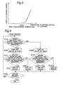
- FIG. 3 is a characteristic diagram of an infrared sensor according to the embodiment of the present invention.
- FIG. 4 is a flow chart illustrating heating control on the induction heating cooking device according to the embodiment of the present invention.
- FIG. 1 and FIG. 2 illustrate the structure of an induction heating cooking device according to an embodiment of the present invention.
- the induction heating cooking device according to the present embodiment includes an outer case 1 , and a top plate 2 provided on the upper section of the outer case 1 .
- On the upper surface or the lower surface of the top plate 2 there are displayed heating sections 4 and 5 indicative of positions at which a cooking container 3 such as a pan is to be placed, through printing.
- Under the heating section 4 there is provided a heating coil 8 for heating the cooking container 3 through induction heating.
- Under the heating section 5 there is provided a radiant heater which applies radiant heating to the cooking container.
- a roaster 6 for roasting fish and the like, and an operating section 7 including switches for starting/stopping heating and for controlling the increase and decrease of the firepower.
- the cooking container 3 is placed on the upper surface of the top plate 2 such that it aligns with the heating coil 8 .
- a thermistor 15 as a heat sensitive element is provided such that it contacts with the lower surface of the top plate 2 , at the upper position inside of the center opening section of the heating coil 8 .
- a temperature detection section 11 receives heat, through the thermistor 15 , from the back surface of the top plate 2 to detect the temperature of the cooking container 3 (hereinafter, referred to as a “detected temperature”) and then outputs the detected temperature.
- the top plate 2 is partially or entirely made of a material capable of transmitting infrared radiation therethrough, and an infrared sensor 10 is provided under the top plate 2 .
- the infrared radiation emitted from the portion at the bottom surface of the cooking container 3 enters an infrared-radiation incidence area provided in the top plate 2 , then passes through a tubular-shaped optical guiding tube (not illustrated) provided between the top plate 2 and the infrared sensor 10 and, then, is received by the infrared sensor 10 .
- the infrared sensor 10 receives the infrared radiation emitted from the portion at the bottom surface of the cooking container 3 near and above the center of the heating coil 8 .
- the infrared sensor 10 detects the received infrared radiation and outputs a detection signal based on the quantity of energy of the detected infrared radiation.
- An infrared temperature conversion section 12 converts the detection signal outputted from the infrared sensor 10 into a temperature of the bottom surface of the cooking container 3 (hereinafter, referred to as an “infrared temperature”) and then outputs the converted detection signal.
- the infrared temperature resulted from the conversion by the infrared temperature conversion section 12 is outputted to a heating control section 9 provided under the heating coil 8 .
- the infrared sensor 10 is constituted by a light receiving element constituted by a silicon photodiode which detects infrared radiation emitted from the cooking container 3 , and an amplifier which amplifies the quantity of energy of the infrared radiation detected by the light receiving element for creating a detection signal.
- FIG. 3 illustrates a characteristic of a detection signal outputted from the infrared sensor 10 .
- the infrared sensor 10 outputs a detection signal when the temperature of the bottom surface of the cooking container 3 is equal to or higher than a first predetermined temperature, but outputs no detection signal when the temperature of the bottom surface of the cooking container 3 is lower than the first predetermined temperature.
- the meaning of the terms “the infrared sensor 10 outputs no detection signal” includes not only cases where the infrared sensor 10 does not output the detection signal at all, but also cases where the infrared sensor 10 outputs the detection signal which can not enable the heating control section 9 to read the temperature change at the bottom surface of the cooking container 3 based on the change in the magnitudes of the detection signal, that is, a faint detection signal which can not enable the heating control section 9 to actually detect the change of the infrared temperature.
- the first predetermined temperature is higher than a maximum temperature value optimum for cooking for fried foods (for example, 230 degrees C.), but is lower than a maximum temperature value optimum for cooking for sauteed foods (for example, 300 degrees C.). In the present embodiment, the first predetermined temperature is 250 degrees C.
- the detected temperature which is detected by the temperature detection section 11 and the infrared temperature resulted from the conversion by the infrared temperature conversion section 12 are outputted to the heating control section 9 provided under the heating coil 8 .
- the heating control section 9 includes an inverter circuit which supplies a high-frequency electric current to the heating coil 8 , and an inverter control circuit which controls a switching element in the inverter circuit to control the supply of electric power to the heating coil 8 .
- the heating control section 9 controls the amount of the high-frequency electric current supplied to the heating coil 8 , based on the detected temperature from the temperature detection section 11 and the infrared temperature from the infrared temperature conversion section 12 , thereby controlling the amount of heating electric power to the cooking container 3 .
- the heating control section 9 determines whether or not the infrared temperature outputted from the infrared temperature conversion section 12 is equal to or higher than the first predetermined temperature, that is, whether or not the infrared sensor 10 is outputting a detection signal. If the infrared sensor 10 is outputting a detection signal, the heating control section 9 operates based on the infrared temperature outputted from the infrared temperature conversion section 12 . Further, if the infrared temperature becomes equal to or higher than a second predetermined temperature, the heating control section 9 performs control in such a way as to stop the supply of electric power to the heating coil 8 or in such a way as to reduce the amount of electric power supplied thereto.
- the heating control section 9 operates based on the detected temperature outputted from the temperature detection section 11 . Further, if the detected temperature is equal to or higher than a third predetermined temperature, the heating control section 9 performs control in such a way as to stop the supply of electric power to the cooking container 3 or in such a way as to reduce the amount of heating electric power.
- the heating control section 9 makes comparison between the infrared temperature from the infrared temperature conversion section 12 and the second predetermined temperature or comparison between the detected temperature from the temperature detection section 11 and the third predetermined temperature, for controlling the ON/OFF of the supply of electric power to the cooking container 3 or the increase and decrease of the amount of heating electric power.
- the second predetermined temperature is a temperature at which the cooking container 3 is before it rises to the temperature which causes ignition of oil (about 330 degrees C.).
- the second predetermined temperature is 300 degrees C.
- the third temperature is equal to the second temperature.
- the temperature detection section 11 , the infrared temperature conversion section 12 and the heating control section 9 described above are constituted by circuits including a microcomputer.
- the induction heating cooking device further includes a state display section 13 constituted by an LED.
- a state display section 13 constituted by an LED.
- the state display section 13 is lighted.
- the infrared sensor 10 outputs no detection signal, that is, when the temperature of the bottom surface of the cooking container 3 is lower than the first predetermined temperature
- the state display section 13 is extinguished.
- the state display section 13 is lighted or extinguished as described above, which notifies the user of the fact that the bottom surface of the cooking container 3 is at a high temperature equal to or higher than the first predetermined temperature (250 degrees C., in the present embodiment) or is not at such a high temperature.
- the induction heating cooking device further includes a n informing section 14 which outputs sounds.
- the informing section 14 changes the content of notification, based on whether the infrared sensor 10 is outputting a detection signal, and based on whether the infrared temperature from the infrared temperature conversion section 12 or the detected temperature from the temperature detection section 11 is higher than the second predetermined temperature or the third predetermined temperature. For example, when the infrared sensor 10 starts outputting a detection signal, the informing section 14 generates, through sounds, a notification describing “the pan is at a high temperature, and please take notice it”, “the temperature of the pan has reached 250 degrees C.” or “the temperature of the pan has reached a temperature suitable for sauteed vegetables”.
- the informing section 14 generates a notification describing “the temperature of the pan has reached a high temperature, and the heating has been temporarily stopped” or “the temperature of the pan has reached a high temperature, and the firepower has been decreased”.
- the induction heating cooking device having the aforementioned structure according to the present embodiment outputs the detection signal having output values increasing with increasing infrared temperature, when the infrared temperature from the infrared sensor 10 is equal to or higher than the first predetermined temperature set to be higher than 230 degrees C.
- the induction heating cooking device outputs no detection signal, substantially.
- the infrared temperature is compared with the second predetermined temperature for turning on or off the heating of the cooking container 3 or for increasing or decreasing the amount of heating electric power.
- the heating is temporarily stopped or the amount of electric power for heating the cooking container 3 is reduced. If the infrared temperature is dropped to below the second predetermined temperature, the heating is restarted or the amount of heating electric power is restored.
- the heating of the cooking container 3 is turned on or off or the amount of heating electric power is increased or decreased, based on whether or not the detected temperature from the temperature detection section 11 is equal to or higher than the third predetermined temperature.
- FIG. 4 is a flow chart illustrating operations for controlling the heating of the induction heating cooking device according to the present embodiment. This control is performed based on programs stored in the microcomputer included in the heating control section 9 .
- the heating control section 9 starts supplying a high-frequency electric current to the heating coil 8 .
- This structure starts heating of the cooking container 3 .
- the heating control section 9 determines whether or not the infrared sensor 10 is outputting a detection signal, that is, whether or not the infrared temperature resulted from the conversion by the infrared temperature conversion section 12 is lower than the first predetermined temperature (250 degrees C., in the present embodiment)(S 100 ).
- the heating control section 9 turns off the state display section 13 (S 101 ).
- the heating control section 9 determines whether or not the detected temperature from the temperature detection section 11 is equal to or higher than the third predetermined temperature (300 degrees C., in the present embodiment) (S 102 ). If the detected temperature from the temperature detection section 11 is equal to or higher than the third predetermined temperature, the heating control section 9 stops the supply of electric power to the heating coil 8 to turn off the heating of the cooking container 3 (S 103 ).
- the heating control section 9 turns off the heating. If the detected temperature from the temperature detection section 11 is lower than the third predetermined temperature, the heating control section 9 supplies electric power to the heating coil 8 to turn on the heating of the cooking container 3 (S 104 ).
- step S 103 when the heating of the cooking container 3 has been stopped, this means that the stopping of the supply of electric power to the heating coil 8 is continued, as it now stands.
- step S 104 when the cooking container 3 has been heated, this means that the supply of electric power to the heating coil 8 is continued, as it now stands.
- the heating control section 9 determines whether or not the user has operated a switch for generating a command for stopping the heating of the induction heating cooking device (S 105 ). If the switch for generating a command for stopping the heating has not been operated, the heating control section 9 returns to step 100 . If the switch for generating a command for stopping the heating has been operated, the heating control section 9 stops the heating of the cooking container 3 .
- the state display section 13 is turned on (S 106 ).
- the heating control section 9 determines whether or not the infrared temperature from the infrared temperature conversion section 12 is equal to or higher than the second predetermined temperature (300 degrees C., in the present embodiment)(S 107 ). If the infrared temperature from the infrared temperature conversion section 12 is equal to or higher than the second predetermined temperature, the heating control section 9 stops the supply of electric power to the heating coil 8 to turn off the heating of the cooking container 3 (S 108 ).
- the heating control section 9 supplies electric power to the heating coil 8 to turn on the heating of the cooking container 3 (S 109 ). In this case, if the heating is turned off in step S 108 when the heating of the cooking container has been stopped, this means that the stopping of the supply of electric power to the heating coil is continued, as it now stands. If the heating is turned on in step S 109 when the cooking container 3 has been heated, this means that the supply of electric power to the heating coil is continued, as it now stands. After steps S 108 and 109 , the heating control section 9 determines whether or not the switch for generating a command for stopping the heating of the induction heating cooking device has been operated (S 105 ).
- the induction heating cooking device includes the infrared sensor 10 and, when the infrared temperature is equal to or higher than 250 degrees C. (the first predetermined temperature), the infrared sensor 10 outputs the detection signal having output values increasing with increasing temperature of the bottom surface of the cooking container 3 , that is, the detection signal having output values increasing with increasing quantity of energy of the detected infrared radiation. Further, the infrared sensor 10 is structured such that it outputs no detection signal substantially, when the temperature of the bottom surface of the cooking container 3 detected by the infrared sensor 10 is lower than the first predetermined temperature.
- the heating control section 9 controls the ON/OFF of the heating, based on the detected temperature from the temperature detection section 11 , when the temperature resulted from the conversion by the infrared temperature conversion section 12 is lower than 250 degrees C. Namely, in cases of cooking at a high temperature (280 degrees C., for example), such as in cases for cooking for sauteed foods, the heating control section 9 controls the heating, using the infrared sensor 10 , while, in cases of cooking at a temperature which is not high (for example, 180 degrees C.), such as in cases of cooking for fried foods, the heating control section 9 controls the heating, based on the temperature detection section 11 .
- the ignition temperature of oil is about 330 degrees C.
- the oil temperature does not abruptly rise, but, in cases of using a small amount of oil, such as in cases of cooking for sauteed, the oil temperature abruptly rises, and it is necessary to detect the rise of the oil temperature if the oil temperature abruptly rises.
- the ON/OFF of heating is controlled based on the infrared sensor 10 with excellent temperature followability. Accordingly, even if the oil temperature abruptly rises in cases of using a small amount of oil, it is possible to detect, immediately, the fact that the oil temperature has reached 300 degrees C. (the second predetermined temperature) before the oil temperature reaches the ignition temperature. Accordingly, it is possible to prevent the oil temperature from reaching the ignition temperature (330 degrees C., for example), by temporarily stopping the heating or reducing the amount of heating electric power. Accordingly, even in cases of cooking at a high temperature, by heating, using a small amount of oil, such as in cases of cooking for sauteed foods and the like, it is possible to perform cooking safely.
- the infrared sensor 10 When the infrared temperature is lower than 250 degrees C., the infrared sensor 10 outputs no detection signal, which prevents the heating electric power from being reduced based on the infrared sensor 10 . Further, since there is no possibility of the ignition of oil, it is possible to control the temperature of the cooking container 3 using the thermistor which has poor temperature followability but facilitates control at a stable state. A sufficiently-practical temperature adjusting function can be ensured in cases of cooking for fried foods, with an inexpensive structure, using the detection output of the thermistor 15 , except for its poor followability with respect to abrupt temperature rises in the cooling container 3 .
- the infrared sensor 10 detects the quantity of energy of the infrared radiation emitted from a certain portion of the cooking container 3 , which causes the slope of detection signal detected by the infrared sensor 10 to follow the abrupt temperature change in the cooking container 3 .
- the quantity of energy of infrared radiation emitted from the cooking container 3 and the amount of change in the quantity of energy of infrared radiation with respect to the temperature change in the cooking container 3 are varied depending on the material of the cooking container 3 , which makes it difficult to determine the absolute value of the temperature of the cooking container 3 .
- the infrared sensor 10 is structured to output a detection signal when the infrared temperature is equal to or higher than 250 degrees C., which enables making a determination that the temperature of the cooking container is 250 degrees C.
- the infrared sensor 10 when the infrared sensor 10 starts outputting the detection signal, thereby making it easier to determine the absolute value of the temperature of the cooking container 3 around the ignition temperature of oil. Namely, it is possible to increase the detection sensitivity of the infrared sensor 10 to the temperature of the cooking container 3 around the ignition temperature of oil. Accordingly, even if the oil temperature abruptly changes in the case of using a small amount of oil, it is possible to detect, with higher accuracy, the temperature of the cooking container 3 when it is at a higher temperature before the occurrence of ignition of the oil.
- the detection sensitivity is increased, it is possible to turn off the heating before the occurrence of ignition of oil, even if the output of the heating coil 8 is increased. This enables increasing the output of the heating coil 8 for rapidly raising the temperature of the oil, in cases of cooking for fried foods and the like.
- the infrared sensor 10 is required only to output the detection signal when the infrared temperature is equal to or higher than 250 degrees C., which enables use of an inexpensive light receiving element capable of temperature detection only when the infrared temperature is higher, such as a silicon photodiode. Further, it is possible to easily make a determination that the temperature of the cooking container is 250 degrees C., if a detection signal is outputted. This enables simplification of the structure of the infrared temperature conversion section 12 .
- the state display section 13 and the informing section 14 can notify the user of the fact that the temperature of the cooking container 3 is high, thereby realizing a safe induction heating cooking device capable of being used by the user with peace of mind. Further, if the state display section 13 performs display or the informing section 14 generates a notification when the temperature is not high, it is possible to recognize that the infrared sensor 10 is abnormal.
- step 103 and step 108 in FIG. 4 the amount of electric power for heating the cooking container 3 can be reduced, without stopping the heating.
- step 104 and step 109 the amount of heating electric power can be restored, that is, it can be increased.
- the infrared temperature is equal to or higher than the first predetermined temperature, it is determined that the infrared sensor 10 is normally operated and, the heating coil 8 is controlled based on the infrared sensor 10 . Accordingly, due to the insertion of a cooking ingredient into the cooking container 3 , the temperature of the bottom surface of the cooking container 3 is abruptly decreased, and the infrared temperature detected by the infrared sensor 10 becomes lower than the second predetermined temperature. In this case, even if the detection temperature based on the thermistor 15 with poor temperature followability is higher than the third temperature, it is possible to restore the heating electric power based on the infrared sensor 10 . This enables heating the cooking ingredient at a high temperature.
- the first predetermined temperature is set to 250 degrees C., which is higher than 230 degrees C. but is lower than the second predetermined temperature.
- this temperature can have a value different from 250 degrees C.
- it is desirable that the first predetermined temperature is about 250 degrees C. (in the range of 240 to 260 degrees C.).
- the infrared sensor 10 does not output the detection signal during normal cooking for fried foods, which prevents the heating output from being inadvertently suppressed by the output from the infrared sensor 10 .
- the infrared temperature conversion section 12 is provided, but the infrared temperature conversion section 12 can be eliminated. Since the infrared temperature conversion section 12 converts analog temperature information outputted from the infrared sensor 10 into digital temperature information in a different signal form, the detection signal from the infrared sensor 10 can be inputted, as temperature information, to the heating control section 9 , without through the infrared temperature conversion section 12 . Even in this case, similarly to in the present embodiment, the heating control section 9 can control the supply of electric power to the heating coil 8 for adjusting the temperature of the bottom surface of the cooking container 3 .
- the infrared sensor 10 is provided near the center of the center opening part of the heating coil 8
- the infrared sensor 10 can be placed near the inner periphery of the heating coil 8 so as to be deviated from the center of the heating coil 8
- a single heating coil 8 can be constituted by an inner coil and an outer coil in such a way that the heating coil 8 is partitioned into the inner coil and the outer coil, and an infrared-radiation incidence area can be formed in the top plate 2 between the inner coil and the outer coil for enabling measurement at the portion of the cooking container 3 which is positioned above the gap between the windings of the heating coil 8 .
- the thermistor 15 is placed at the upper portion at the center of the heating coil 8 as illustrated in FIG. 2 .
- the thermistor 15 can be placed in the center opening part of the heating coil 8 or between the windings in the heating coil 8 such that the thermistor 15 is deviated from the center of the heating coil 8 , which can also offer similar effects as those described above.
- the third predetermined temperature can be made variable, not be fixed.
- the third predetermined temperature to be compared with the detected temperature from the temperature detection section 11 can be set to be a temperature higher than that when the infrared temperature is lower than the first predetermined temperature or lower than the fourth predetermined temperature.
- the third predetermined temperature when the infrared temperature is equal to or higher than the first predetermined temperature or equal to or higher than the fourth predetermined temperature, can be set to 300 degrees C., but when the infrared temperature is lower than the first predetermined temperature or lower than the fourth predetermined temperature, the third predetermined temperature can be set to 250 degrees C. Further, in cases where the user is enabled to make selections in a cooking menu, the value of the third predetermined temperature can be varied according to the content selected in the cooking menu, as follows.
- the third predetermined temperature when the user performs cooking with a sauteed-food setting, the third predetermined temperature can be set to 300 degrees C., while, when he or she performs cooking with a fried-food setting and with a boiled-food setting, the third predetermined temperature can be set to 160 to 230 degrees C. and 130 degrees C., respectively. Also, the third predetermined temperature can be set according to the amount of heating electric power, such that the third predetermined temperature is decreased with increasing amount of heating electric power. In the case where the third predetermined temperature is kept fixed, due to the insertion of a cooking ingredient into the cooking container 3 , the temperature of the cooking container 3 may be abruptly dropped.
- This structure may cause the detected temperature based on the thermistor 15 with poor temperature followability to still exceed the third predetermined temperature, even if the infrared temperature from the infrared sensor 10 becomes lower than the first predetermined temperature. In this case, the heating is turned off, which prevents the temperature of the cooking container 3 from reaching a high temperature required for cooking, thereby degrading the usability in cases where cooking with higher firepower is desired.
- the third predetermined temperature variable as described above, it is possible to realize higher firepower, to address the aforementioned problem.
- the third predetermined temperature can be set to be a temperature higher than that when the change of the infrared temperature is not proper and it is determined that the infrared sensor 10 functions improperly.
- the heating control section when the infrared temperature based on the infrared sensor 10 is lower than the first predetermined temperature, the heating control section operates based on the detected temperature from the temperature detection section 11 , and makes comparison between the detected temperature and the third predetermined temperature for stopping the heating or reducing the amount of electric power for heating the cooking container 3 .
- the heating can be stopped or the amount of electric power for heating the cooking container 3 can be reduced, based on the detected temperature from the temperature detection section 11 .
- the heating can be stopped based on the detected temperature from the temperature detection section 11 . This can cause the temperature detection section 11 to have the back up function in cases where the infrared sensor 10 can not function due to failures and the like.
- the operation for stopping the heating or suppressing the amount of electric power for heating the cooking container 3 can be performed, in cases of satisfaction of any of the condition where the infrared temperature detected by the infrared sensor 10 is equal to or higher than the second predetermined temperature and the condition where the detected temperature from the temperature detection section 11 is equal to or higher than the third predetermined temperature.
- the third predetermined temperature used in step S 102 in FIG. 4 and the second predetermined temperature used in step 107 are equal to each other, but these temperatures can be set to be different temperatures.
- the state display section 13 is not limited to an LED.
- it can be a liquid crystal.
- the light receiving element in the infrared sensor 10 can be constituted by a device capable of detecting both lower temperatures and higher temperatures.
- the light receiving element in the infrared sensor 10 can be constituted by an element such as a PIN photodiode made of Ge (germanium) or InGaAs (indium gallium arsenide).
- the amplifier in the infrared sensor constituted by the light receiving element and the amplifier, the amplifier can be adapted to output a detection signal when the infrared temperature is equal to or higher than the first predetermined temperature (for example, 250 degrees C.).
- the induction heating cooking device is capable of having increased detection sensitivity to higher temperatures in cases of using a small amount of oil and therefore is applicable as a heating cooking device for cooking for sauteed foods by heating.
Landscapes
- Physics & Mathematics (AREA)
- Electromagnetism (AREA)
- Induction Heating Cooking Devices (AREA)
- Electric Stoves And Ranges (AREA)
Applications Claiming Priority (3)
| Application Number | Priority Date | Filing Date | Title |
|---|---|---|---|
| JP2006-029376 | 2006-02-07 | ||
| JP2006029376 | 2006-02-07 | ||
| PCT/JP2007/052125 WO2007091597A1 (ja) | 2006-02-07 | 2007-02-07 | 誘導加熱調理器 |
Publications (2)
| Publication Number | Publication Date |
|---|---|
| US20090014438A1 US20090014438A1 (en) | 2009-01-15 |
| US8334487B2 true US8334487B2 (en) | 2012-12-18 |
Family
ID=38345193
Family Applications (1)
| Application Number | Title | Priority Date | Filing Date |
|---|---|---|---|
| US12/278,696 Active 2030-01-16 US8334487B2 (en) | 2006-02-07 | 2007-02-07 | Induction heating cooking device |
Country Status (8)
| Country | Link |
|---|---|
| US (1) | US8334487B2 (ja) |
| EP (1) | EP1986468B1 (ja) |
| JP (1) | JP4776636B2 (ja) |
| CN (1) | CN101379876B (ja) |
| CA (1) | CA2641568C (ja) |
| ES (1) | ES2425231T3 (ja) |
| HK (1) | HK1126076A1 (ja) |
| WO (1) | WO2007091597A1 (ja) |
Cited By (1)
| Publication number | Priority date | Publication date | Assignee | Title |
|---|---|---|---|---|
| US10813172B2 (en) | 2018-05-23 | 2020-10-20 | Haier Us Appliance Solutions, Inc. | Cooktop appliances and control methods for the same |
Families Citing this family (24)
| Publication number | Priority date | Publication date | Assignee | Title |
|---|---|---|---|---|
| ES2443694T3 (es) * | 2007-01-10 | 2014-02-20 | Panasonic Corporation | Electrodoméstico de calentamiento por inducción para cocinado |
| WO2008120447A1 (ja) * | 2007-03-12 | 2008-10-09 | Panasonic Corporation | 誘導加熱調理器 |
| EP2173139B1 (en) * | 2007-06-21 | 2012-08-15 | Panasonic Corporation | Induction heating cooker |
| ES2388805T3 (es) * | 2007-08-13 | 2012-10-18 | Panasonic Corporation | Cocina de calentamiento por inducción |
| JP5045305B2 (ja) * | 2007-08-21 | 2012-10-10 | パナソニック株式会社 | 誘導加熱調理器 |
| JP4985240B2 (ja) * | 2007-08-31 | 2012-07-25 | パナソニック株式会社 | 誘導加熱調理器 |
| JP5029229B2 (ja) * | 2007-08-31 | 2012-09-19 | パナソニック株式会社 | 誘導加熱調理器 |
| JP5045375B2 (ja) * | 2007-11-07 | 2012-10-10 | パナソニック株式会社 | 誘導加熱調理器 |
| US9226343B2 (en) | 2007-11-30 | 2015-12-29 | Nuwave, Llc | Apparatus, system, method and computer program product for precise multistage programmable induction cooktop |
| ES2629443T3 (es) * | 2008-02-19 | 2017-08-09 | Panasonic Corporation | Dispositivos de cocción por calentamiento por inducción |
| JP5033733B2 (ja) * | 2008-07-31 | 2012-09-26 | 日立アプライアンス株式会社 | 誘導加熱調理器 |
| JP2009259836A (ja) * | 2009-05-25 | 2009-11-05 | Hitachi Appliances Inc | 誘導加熱調理器 |
| JP4981106B2 (ja) * | 2009-07-15 | 2012-07-18 | 三菱電機株式会社 | 誘導加熱調理器 |
| CA2794691C (en) * | 2010-03-31 | 2017-09-12 | Panasonic Corporation | Induction heating cookware |
| WO2011155205A1 (ja) * | 2010-06-10 | 2011-12-15 | パナソニック株式会社 | 誘導加熱調理器 |
| US9833101B2 (en) | 2011-04-01 | 2017-12-05 | Nuwave, Llc | Pan and method for making |
| JP5999998B2 (ja) * | 2012-07-03 | 2016-09-28 | 三菱電機株式会社 | 誘導加熱調理器及びそのプログラム |
| JP5891151B2 (ja) * | 2012-09-10 | 2016-03-22 | 日立アプライアンス株式会社 | 誘導加熱調理器 |
| GB2511538B (en) * | 2013-03-06 | 2016-06-15 | Basic Holdings | Heating Appliance |
| TWI495399B (zh) * | 2013-03-08 | 2015-08-01 | Delta Electronics Inc | 可增加加熱範圍之電磁感應加熱裝置 |
| US10458951B2 (en) * | 2016-05-03 | 2019-10-29 | GM Global Technology Operations LLC | Cylinder block inspection method and system |
| US11143413B2 (en) * | 2017-12-05 | 2021-10-12 | Zhejiang Jiu Kang Electric Appliances Co., Ltd. | Glass-ceramic cooking apparatus and a method relating to temperature limiting control for preventing cooking oil ignition |
| JP7217421B2 (ja) * | 2018-04-19 | 2023-02-03 | パナソニックIpマネジメント株式会社 | 加熱調理器 |
| FI20185482A1 (fi) * | 2018-05-25 | 2019-11-26 | Safera Oy | Liesivahti, joka hyödyntää eri aallonpituuksia |
Citations (10)
| Publication number | Priority date | Publication date | Assignee | Title |
|---|---|---|---|---|
| JPH03208288A (ja) | 1990-01-09 | 1991-09-11 | Matsushita Electric Ind Co Ltd | 誘導加熱調理器 |
| US5428207A (en) * | 1992-03-14 | 1995-06-27 | E.G.O. Elecktro-Gerate Blanc U. Fischer | Inductive based cooking system |
| CN2422904Y (zh) | 2000-07-04 | 2001-03-14 | 彭根发 | 温控发声锅 |
| JP2003038347A (ja) | 2001-08-03 | 2003-02-12 | Matsushita Electric Ind Co Ltd | 加熱調理器 |
| JP2003109736A (ja) | 2001-09-28 | 2003-04-11 | Osaka Gas Co Ltd | クッキングヒータ装置 |
| JP2003317916A (ja) | 2002-04-26 | 2003-11-07 | Mitsubishi Electric Corp | 誘導加熱調理器 |
| JP2004063199A (ja) | 2002-07-26 | 2004-02-26 | Tiger Vacuum Bottle Co Ltd | 電磁誘導加熱調理方法とこれに用いる誘導加熱調理器 |
| US20040099652A1 (en) * | 2002-11-27 | 2004-05-27 | General Electric Company | Error correction for optical detector in glass-ceramic cooktop appliances |
| JP2005011618A (ja) | 2003-06-18 | 2005-01-13 | Matsushita Electric Ind Co Ltd | 誘導加熱調理器 |
| WO2005053362A1 (ja) | 2003-11-25 | 2005-06-09 | Kabushiki Kaisha Toshiba | 加熱調理器、調理器具および加熱調理システム |
-
2007
- 2007-02-07 WO PCT/JP2007/052125 patent/WO2007091597A1/ja active Search and Examination
- 2007-02-07 ES ES07708164T patent/ES2425231T3/es active Active
- 2007-02-07 EP EP07708164.4A patent/EP1986468B1/en not_active Not-in-force
- 2007-02-07 US US12/278,696 patent/US8334487B2/en active Active
- 2007-02-07 CN CN2007800046179A patent/CN101379876B/zh active Active
- 2007-02-07 CA CA2641568A patent/CA2641568C/en not_active Expired - Fee Related
- 2007-02-07 JP JP2007557867A patent/JP4776636B2/ja active Active
-
2009
- 2009-05-22 HK HK09104698.8A patent/HK1126076A1/xx not_active IP Right Cessation
Patent Citations (12)
| Publication number | Priority date | Publication date | Assignee | Title |
|---|---|---|---|---|
| JPH03208288A (ja) | 1990-01-09 | 1991-09-11 | Matsushita Electric Ind Co Ltd | 誘導加熱調理器 |
| US5428207A (en) * | 1992-03-14 | 1995-06-27 | E.G.O. Elecktro-Gerate Blanc U. Fischer | Inductive based cooking system |
| CN2422904Y (zh) | 2000-07-04 | 2001-03-14 | 彭根发 | 温控发声锅 |
| JP2003038347A (ja) | 2001-08-03 | 2003-02-12 | Matsushita Electric Ind Co Ltd | 加熱調理器 |
| JP2003109736A (ja) | 2001-09-28 | 2003-04-11 | Osaka Gas Co Ltd | クッキングヒータ装置 |
| JP2003317916A (ja) | 2002-04-26 | 2003-11-07 | Mitsubishi Electric Corp | 誘導加熱調理器 |
| JP2004063199A (ja) | 2002-07-26 | 2004-02-26 | Tiger Vacuum Bottle Co Ltd | 電磁誘導加熱調理方法とこれに用いる誘導加熱調理器 |
| US20040099652A1 (en) * | 2002-11-27 | 2004-05-27 | General Electric Company | Error correction for optical detector in glass-ceramic cooktop appliances |
| JP2005011618A (ja) | 2003-06-18 | 2005-01-13 | Matsushita Electric Ind Co Ltd | 誘導加熱調理器 |
| WO2005053362A1 (ja) | 2003-11-25 | 2005-06-09 | Kabushiki Kaisha Toshiba | 加熱調理器、調理器具および加熱調理システム |
| US20070080158A1 (en) * | 2003-11-25 | 2007-04-12 | Kabushiki Kaisha Toshiba | Heat cooking apparatus, cooking tool and heat cooking system |
| US7473872B2 (en) | 2003-11-25 | 2009-01-06 | Kabushiki Kaisha Toshiba | Cooking tool |
Cited By (1)
| Publication number | Priority date | Publication date | Assignee | Title |
|---|---|---|---|---|
| US10813172B2 (en) | 2018-05-23 | 2020-10-20 | Haier Us Appliance Solutions, Inc. | Cooktop appliances and control methods for the same |
Also Published As
| Publication number | Publication date |
|---|---|
| EP1986468A1 (en) | 2008-10-29 |
| US20090014438A1 (en) | 2009-01-15 |
| JP4776636B2 (ja) | 2011-09-21 |
| CN101379876A (zh) | 2009-03-04 |
| ES2425231T3 (es) | 2013-10-14 |
| WO2007091597A1 (ja) | 2007-08-16 |
| EP1986468B1 (en) | 2013-06-12 |
| CN101379876B (zh) | 2012-02-01 |
| CA2641568C (en) | 2014-01-28 |
| EP1986468A4 (en) | 2011-12-28 |
| HK1126076A1 (en) | 2009-08-21 |
| JPWO2007091597A1 (ja) | 2009-07-02 |
| CA2641568A1 (en) | 2007-08-16 |
Similar Documents
| Publication | Publication Date | Title |
|---|---|---|
| US8334487B2 (en) | Induction heating cooking device | |
| US9035223B2 (en) | Induction heat cooking device | |
| JP4965648B2 (ja) | 誘導加熱調理器 | |
| JP5655777B2 (ja) | 誘導加熱調理器 | |
| US8212192B2 (en) | Induction heating cooker | |
| EP2405712B1 (en) | Induction heating device | |
| JP4939248B2 (ja) | 誘導加熱調理器 | |
| JP4492135B2 (ja) | 誘導加熱調理器 | |
| JP2007287465A (ja) | 誘導加熱装置 | |
| JP5218286B2 (ja) | 誘導加熱調理器 | |
| JP4497196B2 (ja) | 誘導加熱調理器 | |
| JP5062013B2 (ja) | 誘導加熱調理器 | |
| JP5045650B2 (ja) | 誘導加熱調理器 | |
| JP4983739B2 (ja) | 誘導加熱調理器 | |
| JP5050791B2 (ja) | 誘導加熱調理器 | |
| JP2005150013A (ja) | 誘導加熱調理器 | |
| JP2009238686A (ja) | 誘導加熱調理器 | |
| JP5684153B2 (ja) | 誘導加熱調理器及びその制御方法 |
Legal Events
| Date | Code | Title | Description |
|---|---|---|---|
| AS | Assignment |
Owner name: PANASONIC CORPORATION, JAPAN Free format text: ASSIGNMENT OF ASSIGNORS INTEREST;ASSIGNORS:OHASHI, MASAHARU;WATANABE, KENJI;TOMINAGA, HIROSHI;AND OTHERS;REEL/FRAME:021793/0050;SIGNING DATES FROM 20080722 TO 20080728 Owner name: PANASONIC CORPORATION, JAPAN Free format text: ASSIGNMENT OF ASSIGNORS INTEREST;ASSIGNORS:OHASHI, MASAHARU;WATANABE, KENJI;TOMINAGA, HIROSHI;AND OTHERS;SIGNING DATES FROM 20080722 TO 20080728;REEL/FRAME:021793/0050 |
|
| FEPP | Fee payment procedure |
Free format text: PAYOR NUMBER ASSIGNED (ORIGINAL EVENT CODE: ASPN); ENTITY STATUS OF PATENT OWNER: LARGE ENTITY |
|
| STCF | Information on status: patent grant |
Free format text: PATENTED CASE |
|
| FEPP | Fee payment procedure |
Free format text: PAYER NUMBER DE-ASSIGNED (ORIGINAL EVENT CODE: RMPN); ENTITY STATUS OF PATENT OWNER: LARGE ENTITY Free format text: PAYOR NUMBER ASSIGNED (ORIGINAL EVENT CODE: ASPN); ENTITY STATUS OF PATENT OWNER: LARGE ENTITY |
|
| FPAY | Fee payment |
Year of fee payment: 4 |
|
| MAFP | Maintenance fee payment |
Free format text: PAYMENT OF MAINTENANCE FEE, 8TH YEAR, LARGE ENTITY (ORIGINAL EVENT CODE: M1552); ENTITY STATUS OF PATENT OWNER: LARGE ENTITY Year of fee payment: 8 |