US7727673B2 - Cathode active material, method of manufacturing the same, and battery - Google Patents
Cathode active material, method of manufacturing the same, and battery Download PDFInfo
- Publication number
- US7727673B2 US7727673B2 US11/685,571 US68557107A US7727673B2 US 7727673 B2 US7727673 B2 US 7727673B2 US 68557107 A US68557107 A US 68557107A US 7727673 B2 US7727673 B2 US 7727673B2
- Authority
- US
- United States
- Prior art keywords
- active material
- coating layer
- cathode active
- cathode
- manganese
- Prior art date
- Legal status (The legal status is an assumption and is not a legal conclusion. Google has not performed a legal analysis and makes no representation as to the accuracy of the status listed.)
- Expired - Fee Related
Links
Images


Classifications
-
- H—ELECTRICITY
- H01—ELECTRIC ELEMENTS
- H01M—PROCESSES OR MEANS, e.g. BATTERIES, FOR THE DIRECT CONVERSION OF CHEMICAL ENERGY INTO ELECTRICAL ENERGY
- H01M4/00—Electrodes
- H01M4/02—Electrodes composed of, or comprising, active material
- H01M4/36—Selection of substances as active materials, active masses, active liquids
- H01M4/362—Composites
- H01M4/366—Composites as layered products
-
- B—PERFORMING OPERATIONS; TRANSPORTING
- B82—NANOTECHNOLOGY
- B82Y—SPECIFIC USES OR APPLICATIONS OF NANOSTRUCTURES; MEASUREMENT OR ANALYSIS OF NANOSTRUCTURES; MANUFACTURE OR TREATMENT OF NANOSTRUCTURES
- B82Y30/00—Nanotechnology for materials or surface science, e.g. nanocomposites
-
- C—CHEMISTRY; METALLURGY
- C01—INORGANIC CHEMISTRY
- C01G—COMPOUNDS CONTAINING METALS NOT COVERED BY SUBCLASSES C01D OR C01F
- C01G23/00—Compounds of titanium
- C01G23/04—Oxides; Hydroxides
-
- C—CHEMISTRY; METALLURGY
- C01—INORGANIC CHEMISTRY
- C01G—COMPOUNDS CONTAINING METALS NOT COVERED BY SUBCLASSES C01D OR C01F
- C01G25/00—Compounds of zirconium
- C01G25/02—Oxides
-
- C—CHEMISTRY; METALLURGY
- C01—INORGANIC CHEMISTRY
- C01G—COMPOUNDS CONTAINING METALS NOT COVERED BY SUBCLASSES C01D OR C01F
- C01G51/00—Compounds of cobalt
- C01G51/40—Cobaltates
- C01G51/42—Cobaltates containing alkali metals, e.g. LiCoO2
-
- C—CHEMISTRY; METALLURGY
- C01—INORGANIC CHEMISTRY
- C01G—COMPOUNDS CONTAINING METALS NOT COVERED BY SUBCLASSES C01D OR C01F
- C01G51/00—Compounds of cobalt
- C01G51/40—Cobaltates
- C01G51/42—Cobaltates containing alkali metals, e.g. LiCoO2
- C01G51/44—Cobaltates containing alkali metals, e.g. LiCoO2 containing manganese
-
- C—CHEMISTRY; METALLURGY
- C01—INORGANIC CHEMISTRY
- C01G—COMPOUNDS CONTAINING METALS NOT COVERED BY SUBCLASSES C01D OR C01F
- C01G53/00—Compounds of nickel
- C01G53/40—Nickelates
- C01G53/42—Nickelates containing alkali metals, e.g. LiNiO2
-
- C—CHEMISTRY; METALLURGY
- C01—INORGANIC CHEMISTRY
- C01G—COMPOUNDS CONTAINING METALS NOT COVERED BY SUBCLASSES C01D OR C01F
- C01G53/00—Compounds of nickel
- C01G53/40—Nickelates
- C01G53/42—Nickelates containing alkali metals, e.g. LiNiO2
- C01G53/44—Nickelates containing alkali metals, e.g. LiNiO2 containing manganese
-
- H—ELECTRICITY
- H01—ELECTRIC ELEMENTS
- H01M—PROCESSES OR MEANS, e.g. BATTERIES, FOR THE DIRECT CONVERSION OF CHEMICAL ENERGY INTO ELECTRICAL ENERGY
- H01M10/00—Secondary cells; Manufacture thereof
- H01M10/05—Accumulators with non-aqueous electrolyte
- H01M10/052—Li-accumulators
- H01M10/0525—Rocking-chair batteries, i.e. batteries with lithium insertion or intercalation in both electrodes; Lithium-ion batteries
-
- H—ELECTRICITY
- H01—ELECTRIC ELEMENTS
- H01M—PROCESSES OR MEANS, e.g. BATTERIES, FOR THE DIRECT CONVERSION OF CHEMICAL ENERGY INTO ELECTRICAL ENERGY
- H01M4/00—Electrodes
- H01M4/02—Electrodes composed of, or comprising, active material
- H01M4/13—Electrodes for accumulators with non-aqueous electrolyte, e.g. for lithium-accumulators; Processes of manufacture thereof
- H01M4/131—Electrodes based on mixed oxides or hydroxides, or on mixtures of oxides or hydroxides, e.g. LiCoOx
-
- H—ELECTRICITY
- H01—ELECTRIC ELEMENTS
- H01M—PROCESSES OR MEANS, e.g. BATTERIES, FOR THE DIRECT CONVERSION OF CHEMICAL ENERGY INTO ELECTRICAL ENERGY
- H01M4/00—Electrodes
- H01M4/02—Electrodes composed of, or comprising, active material
- H01M4/13—Electrodes for accumulators with non-aqueous electrolyte, e.g. for lithium-accumulators; Processes of manufacture thereof
- H01M4/139—Processes of manufacture
- H01M4/1391—Processes of manufacture of electrodes based on mixed oxides or hydroxides, or on mixtures of oxides or hydroxides, e.g. LiCoOx
-
- H—ELECTRICITY
- H01—ELECTRIC ELEMENTS
- H01M—PROCESSES OR MEANS, e.g. BATTERIES, FOR THE DIRECT CONVERSION OF CHEMICAL ENERGY INTO ELECTRICAL ENERGY
- H01M4/00—Electrodes
- H01M4/02—Electrodes composed of, or comprising, active material
- H01M4/36—Selection of substances as active materials, active masses, active liquids
- H01M4/362—Composites
- H01M4/364—Composites as mixtures
-
- H—ELECTRICITY
- H01—ELECTRIC ELEMENTS
- H01M—PROCESSES OR MEANS, e.g. BATTERIES, FOR THE DIRECT CONVERSION OF CHEMICAL ENERGY INTO ELECTRICAL ENERGY
- H01M4/00—Electrodes
- H01M4/02—Electrodes composed of, or comprising, active material
- H01M4/36—Selection of substances as active materials, active masses, active liquids
- H01M4/48—Selection of substances as active materials, active masses, active liquids of inorganic oxides or hydroxides
- H01M4/52—Selection of substances as active materials, active masses, active liquids of inorganic oxides or hydroxides of nickel, cobalt or iron
- H01M4/525—Selection of substances as active materials, active masses, active liquids of inorganic oxides or hydroxides of nickel, cobalt or iron of mixed oxides or hydroxides containing iron, cobalt or nickel for inserting or intercalating light metals, e.g. LiNiO2, LiCoO2 or LiCoOxFy
-
- H—ELECTRICITY
- H01—ELECTRIC ELEMENTS
- H01M—PROCESSES OR MEANS, e.g. BATTERIES, FOR THE DIRECT CONVERSION OF CHEMICAL ENERGY INTO ELECTRICAL ENERGY
- H01M4/00—Electrodes
- H01M4/02—Electrodes composed of, or comprising, active material
- H01M4/62—Selection of inactive substances as ingredients for active masses, e.g. binders, fillers
- H01M4/621—Binders
-
- C—CHEMISTRY; METALLURGY
- C01—INORGANIC CHEMISTRY
- C01P—INDEXING SCHEME RELATING TO STRUCTURAL AND PHYSICAL ASPECTS OF SOLID INORGANIC COMPOUNDS
- C01P2002/00—Crystal-structural characteristics
- C01P2002/50—Solid solutions
- C01P2002/52—Solid solutions containing elements as dopants
-
- C—CHEMISTRY; METALLURGY
- C01—INORGANIC CHEMISTRY
- C01P—INDEXING SCHEME RELATING TO STRUCTURAL AND PHYSICAL ASPECTS OF SOLID INORGANIC COMPOUNDS
- C01P2002/00—Crystal-structural characteristics
- C01P2002/50—Solid solutions
- C01P2002/52—Solid solutions containing elements as dopants
- C01P2002/54—Solid solutions containing elements as dopants one element only
-
- C—CHEMISTRY; METALLURGY
- C01—INORGANIC CHEMISTRY
- C01P—INDEXING SCHEME RELATING TO STRUCTURAL AND PHYSICAL ASPECTS OF SOLID INORGANIC COMPOUNDS
- C01P2004/00—Particle morphology
- C01P2004/51—Particles with a specific particle size distribution
-
- C—CHEMISTRY; METALLURGY
- C01—INORGANIC CHEMISTRY
- C01P—INDEXING SCHEME RELATING TO STRUCTURAL AND PHYSICAL ASPECTS OF SOLID INORGANIC COMPOUNDS
- C01P2004/00—Particle morphology
- C01P2004/60—Particles characterised by their size
- C01P2004/61—Micrometer sized, i.e. from 1-100 micrometer
-
- C—CHEMISTRY; METALLURGY
- C01—INORGANIC CHEMISTRY
- C01P—INDEXING SCHEME RELATING TO STRUCTURAL AND PHYSICAL ASPECTS OF SOLID INORGANIC COMPOUNDS
- C01P2004/00—Particle morphology
- C01P2004/60—Particles characterised by their size
- C01P2004/64—Nanometer sized, i.e. from 1-100 nanometer
-
- C—CHEMISTRY; METALLURGY
- C01—INORGANIC CHEMISTRY
- C01P—INDEXING SCHEME RELATING TO STRUCTURAL AND PHYSICAL ASPECTS OF SOLID INORGANIC COMPOUNDS
- C01P2004/00—Particle morphology
- C01P2004/80—Particles consisting of a mixture of two or more inorganic phases
- C01P2004/82—Particles consisting of a mixture of two or more inorganic phases two phases having the same anion, e.g. both oxidic phases
- C01P2004/84—Particles consisting of a mixture of two or more inorganic phases two phases having the same anion, e.g. both oxidic phases one phase coated with the other
-
- C—CHEMISTRY; METALLURGY
- C01—INORGANIC CHEMISTRY
- C01P—INDEXING SCHEME RELATING TO STRUCTURAL AND PHYSICAL ASPECTS OF SOLID INORGANIC COMPOUNDS
- C01P2006/00—Physical properties of inorganic compounds
- C01P2006/40—Electric properties
-
- H—ELECTRICITY
- H01—ELECTRIC ELEMENTS
- H01M—PROCESSES OR MEANS, e.g. BATTERIES, FOR THE DIRECT CONVERSION OF CHEMICAL ENERGY INTO ELECTRICAL ENERGY
- H01M4/00—Electrodes
- H01M4/02—Electrodes composed of, or comprising, active material
- H01M2004/026—Electrodes composed of, or comprising, active material characterised by the polarity
- H01M2004/028—Positive electrodes
-
- H—ELECTRICITY
- H01—ELECTRIC ELEMENTS
- H01M—PROCESSES OR MEANS, e.g. BATTERIES, FOR THE DIRECT CONVERSION OF CHEMICAL ENERGY INTO ELECTRICAL ENERGY
- H01M2300/00—Electrolytes
- H01M2300/0085—Immobilising or gelification of electrolyte
-
- Y—GENERAL TAGGING OF NEW TECHNOLOGICAL DEVELOPMENTS; GENERAL TAGGING OF CROSS-SECTIONAL TECHNOLOGIES SPANNING OVER SEVERAL SECTIONS OF THE IPC; TECHNICAL SUBJECTS COVERED BY FORMER USPC CROSS-REFERENCE ART COLLECTIONS [XRACs] AND DIGESTS
- Y02—TECHNOLOGIES OR APPLICATIONS FOR MITIGATION OR ADAPTATION AGAINST CLIMATE CHANGE
- Y02E—REDUCTION OF GREENHOUSE GAS [GHG] EMISSIONS, RELATED TO ENERGY GENERATION, TRANSMISSION OR DISTRIBUTION
- Y02E60/00—Enabling technologies; Technologies with a potential or indirect contribution to GHG emissions mitigation
- Y02E60/10—Energy storage using batteries
Definitions
- the present application relates to a cathode active material which includes a complex oxide including lithium (Li) and cobalt (Co), a method of manufacturing the cathode active material, and a battery using the cathode active material.
- a cathode active material which includes a complex oxide including lithium (Li) and cobalt (Co)
- Li lithium
- Co cobalt
- transition metal chalcogenides including alkali metal are known as a cathode active material capable of obtaining a battery voltage of approximately 4 V.
- transition metal chalcogenides including alkali metal are known.
- a complex oxide such as lithium cobalt oxide or lithium nickel oxide holds great promise in terms of a high potential, stability and long life, and in particular, lithium cobalt oxide has a high potential, so it is expected that the energy density will be improved by increasing a charge voltage.
- a method of manufacturing a cathode active material including the steps of: forming a precursor coating layer made of a hydroxide including at least one coating element selected from nickel and manganese on a part of complex oxide particles having an average composition represented by Chemical Formula 1 (see below); after forming the precursor coating layer, forming a precursor surface layer including at least one surface element selected from the group consisting of titanium, silicon (Si), magnesium and zirconium on at least a part of the complex oxide particles; and after forming the precursor surface layer, forming a coating layer made of a compound including lithium (Li), the coating element and oxygen (O) and a surface layer made of an oxide including the surface element on at least a part of the complex oxide particles by a heat treatment: Li (1+x) Co (1 ⁇ y) M y O (2 ⁇ z) (Chemical Formula 1)
- M is at least one member selected from the group consisting of magnesium (Mg), aluminum (Al), boron (B), titanium (Ti), vanadium (V), chromium (Cr), manganese (Mn), iron (Fe), nickel (Ni), copper (Cu), zinc (Zn), molybdenum (Mo), tin (Sn), tungsten (W), zirconium (Zr), yttrium (Y), niobium (Nb), calcium (Ca) and strontium (Sr), and the values of x, y and z are within a range of ⁇ 0.10 ⁇ x ⁇ 0.10, 0 ⁇ y ⁇ 0.50 and ⁇ 0.10 ⁇ z ⁇ 0.20, respectively.
- a battery including a cathode, an anode and an electrolyte
- the cathode includes a cathode active material in which a coating layer is arranged on at least a part of complex oxide particles
- the complex oxide particles have an average composition represented by Li (1+x) Co (1 ⁇ y) M y O (2 ⁇ z)
- M is at least one member selected from the group consisting of magnesium, aluminum, boron, titanium, vanadium, chromium, manganese, iron, nickel, copper, zinc, molybdenum, tin, tungsten, zirconium, yttrium, niobium, calcium and strontium
- the values of x, y and z are within a range of ⁇ 0.10 ⁇ x ⁇ 0.10, 0 ⁇ y ⁇ 0.50 and ⁇ 0.10 ⁇ z ⁇ 0.20, respectively
- the coating layer is made of a compound including lithium (Li), at least one coating element selected from nickel and manganese, and
- the surface layer made of an oxide including at least one surface element selected from the group consisting of titanium, silicon, magnesium and zirconium is arranged on the coating layer, so the bonding between particles can be prevented, and the separation of the coating layer and damage to particles can be prevented. Thereby, chemical stability can be further improved. Therefore, in the battery according to the embodiment of the invention which uses the cathode active material, a high capacity can be obtained, and charge-discharge efficiency can be improved.
- the precursor coating layer made of a hydroxide including a coating element is formed on the complex oxide particles, the precursor surface layer including a surface element is formed, and the precursor coating layer and the precursor surface layer are heated, so sintering of particles can be prevented, and bonding between particles can be prevented.
- FIG. 1 is a flowchart showing a method of manufacturing a cathode active material according to an embodiment
- FIG. 2 is a sectional view of a first secondary battery using the cathode active material according to the embodiment
- FIG. 3 is an partially enlarged sectional view of a spirally wound electrode body in the secondary battery shown in FIG. 2 ;
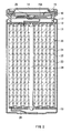
- FIG. 4 is a exploded perspective view of a second secondary battery using the cathode active material according to the embodiment.
- a cathode active material is complex oxide particles represented by Chemical Formula 1 (see below) of which at least a part is covered with a coating layer.
- Chemical Formula 1 the average composition of the complex oxide particles is as shown in Chemical Formula 1, so a high capacity and a high discharge potential can be obtained.
- the value of x is within a range of ⁇ 0.10 ⁇ x ⁇ 0.10, preferably ⁇ 0.08 ⁇ x ⁇ 0.08, and more preferably ⁇ 0.06 ⁇ x ⁇ 0.06.
- a discharge capacity declines, and when the value is larger than the range, lithium is dispersed at the time of forming the coating layer, thereby in some cases, it is difficult to control processes.
- the value of y is within a range of 0 ⁇ y ⁇ 0.50, preferably 0 ⁇ y ⁇ 0.40, and more preferably 0 ⁇ y ⁇ 0.30.
- the element M is not an essential element but a preferable element, because when the element M is included, chemical stability can be improved; however, when the content of the element M increases, the properties of lithium cobalt oxide are impaired, thereby the capacity and the discharge potential decline.
- the value of z is within a range of ⁇ 0.10 ⁇ z ⁇ 0.20, preferably ⁇ 0.08 ⁇ z ⁇ 0.18, and more preferably within ⁇ 0.06 ⁇ z ⁇ 0.16, because the discharge capacity can be further increased within the range.
- the coating layer functions as a reaction inhibition layer, and includes a compound including lithium, at least one coating element selected from nickel and manganese, and oxygen.
- the composition ratio between nickel and manganese in the coating layer is preferably within a range from 100:0 to 30:70, and more preferably from 100:0 to 40:60 at the molar ratio of nickel to manganese. It is because when the amount of manganese increases, the amount of insertion of lithium in the coating layer declines, and the capacity of the cathode active material declines.
- the coating layer may further include at least one member selected from the group consisting of magnesium, aluminum, boron, titanium, vanadium, chromium, iron, cobalt, copper, zinc, molybdenum, tin, tungsten, zirconium, yttrium, niobium, calcium, strontium and silicon as an element, because the stability of the cathode active material can be further improved, and the diffusibility of lithium ions can be further improved.
- the total content of the elements is preferably 40 mol % or less, more preferably 30 mol % or less and most preferably 20 mol % or less with respect to the total of nickel, manganese and the elements in the coating layer. It is because when the content of the elements increases, the amount of insertion of lithium declines, and the capacity of the cathode active material declines.
- the elements may or may not form a solid solution with the compound.
- the amount of the coating layer is preferably within a range from 0.5 wt % to 50 wt % inclusive of the complex oxide particles, more preferably from 1.0 wt % to 40 wt % inclusive, and most preferably from 2.0 wt % to 35 wt % inclusive. It is because when the amount of the coating layer is too large, the capacity declines, and when the amount is too small, it is difficult to sufficiently improve the stability.
- the cathode active material includes a surface layer made of an oxide including at least one surface element selected from the group consisting of titanium, silicon, magnesium and zirconium on at least a part of the coating layer so as to prevent the bonding between particles.
- a surface layer made of an oxide including at least one surface element selected from the group consisting of titanium, silicon, magnesium and zirconium on at least a part of the coating layer so as to prevent the bonding between particles.
- the surface layer may further include at least one member selected from the group consisting of aluminum, boron, vanadium, chromium, manganese, iron, cobalt, nickel, copper, zinc, molybdenum, tin, tungsten, yttrium, niobium, calcium and strontium as an element.
- the total content of the elements is preferably 20 mol % or less with respect to the total of the surface element and the elements in the surface layer, more preferably 15 mol % or less, and most preferably 15 mol % or less. It is because when the content of the elements is too large, the effect of preventing the bonding between particles declines.
- the elements may or may not form a solid solution with the oxide.
- the coating layer and the surface layer can be confirmed by examining a concentration change from the surface to the inside of an element constituting the cathode active material.
- the concentration change can be measured by determining the composition of the cathode active material by Auger Electron Spectroscopy (AES) or SIMS (Secondary Ion Mass Spectrometry) while trimming the cathode active material by sputtering or the like.
- the concentration change can be measured by slowly dissolving the cathode active material in an acid solution, and then determining a time change in the eluted cathode active material by Inductively Coupled Plasma (ICP) spectrometry or the like.
- ICP Inductively Coupled Plasma
- FIG. 1 shows steps of a method of manufacturing the cathode active material.
- a precursor coating layer made of a hydroxide including the coating element is formed on at least a part of the complex oxide particles having an average composition represented by Chemical Formula 1 (step S 110 ).
- the hydroxide is precipitated on the surfaces of the complex oxide particles in an alkali solution including the coating element.
- a nickel compound for example, an inorganic compound such as nickel hydroxide, nickel carbonate, nickel nitrate, nickel fluoride, nickel chloride, nickel bromide, nickel iodide, nickel perchlorate, nickel bromate, nickel iodate, nickel oxide, nickel peroxide, nickel sulfide, nickel sulfate, nickel hydrogensulfate, nickel nitride, nickel nitrite, nickel phosphate or nickel thiocyanate, or an organic compound such as nickel oxalate or nickel acetate is cited.
- an inorganic compound such as nickel hydroxide, nickel carbonate, nickel nitrate, nickel fluoride, nickel chloride, nickel bromide, nickel iodide, nickel perchlorate, nickel bromate, nickel iodate, nickel oxide, nickel peroxide, nickel sulfide, nickel sulfate, nickel hydrogensulfate, nickel nitride, nickel nitrite, nickel phosphate or nickel thiocyan
- a manganese compound for example, an inorganic compound such as manganese hydroxide, manganese carbonate, manganese nitrate, manganese fluoride, manganese chloride, manganese bromide, manganese iodide, manganese chlorate, manganese perchlorate, manganese bromate, manganese iodate, manganese oxide, manganese phosphinate, manganese sulfide, manganese hydrogensulfide, manganese sulfate, manganese hydrogensulfate, manganese thiocyanate, manganese nitrite, manganese phosphate, manganese dihydrogenphosphate or manganese hydrogencarbonate or an organic compound such as manganese oxalate or manganese acetate is cited.
- an inorganic compound such as manganese hydroxide, manganese carbonate, manganese nitrate, manganese fluoride, manganese chloride, manganese
- One or a mixture of two or more compounds selected from the above-referenced compounds including the coating element may be used.
- a precursor surface layer including the surface element is formed on at least a part of complex oxide particles (step S 120 ).
- an oxide including the surface element, or a compound which is converted into an oxide by firing such as a hydroxide, a carbonate or a nitrate can be used, and a plurality of kinds may be used.
- the precursor surface layer may be deposited by mixing through the use of, for example, a ball mill, a jet mill, a stone mill, a fine grinder or the like, and in this case, a dispersion medium such as water or a solvent may be used.
- the precursor surface layer may be deposited by a mechanochemical process such as mechanofusion or a vapor-phase method such as sputtering or chemical vapor deposition (CVD).
- the precursor surface layer may be formed by precipitating a hydroxide in a solution in which the material of the precursor surface layer is dissolved.
- the complex oxide particles on which the precursor coating layer and the precursor surface layer are formed are subjected to a heat treatment to form the coating layer made of a compound including lithium, the coating element and oxygen and the surface layer made of an oxide including the surface element (step S 130 ).
- the heat treatment is preferably performed in air or an oxidation atmosphere such as pure oxygen at a temperature of approximately 300° C. to 1000° C.
- the precursor surface layer is formed on the precursor coating layer, so sintering of particles is prevented, so the bonding between particles is prevented.
- Lithium is dispersed into the coating layer from the complex oxide particles by the heat treatment; however, to adjust the content of lithium in the coating layer, the coating layer may be mixed or impregnated with a lithium compound before the heat treatment.
- the lithium compound may be added on, before or after forming the precursor surface layer.
- lithium compound for example, an inorganic compound such as lithium hydroxide, lithium carbonate, lithium nitrate, lithium fluoride, lithium chloride, lithium bromide, lithium iodide, lithium chlorate, lithium perchlorate, lithium bromate, lithium iodate, lithium oxide, lithium peroxide, lithium sulfide, lithium hydrogensulfide, lithium sulfate, lithium hydrogensulfate, lithium nitride, lithium azide, lithium nitrite, lithium phosphate, lithium dihydrogenphosphate or lithium hydrogencarbonate or an organic compound such as methyllithium, vinyllithium, isopropyllithium, butyllithium, phenyllithium, lithium oxalate or lithium acetate may be used.
- an organic compound such as methyllithium, vinyllithium, isopropyllithium, butyllithium, phenyllithium, lithium oxalate or lithium acetate may be used.
- the complex oxide particles may be formed by crushing secondary particles, if necessary, by a ball mill, a stone mill or the like before forming the precursor coating layer. Further, after forming the coating layer and the surface layer, the particle size of the cathode active material may be adjusted, if necessary, by lightly pulverizing or classification.
- the cathode active material is used in a secondary battery as described below.
- FIG. 2 shows a sectional view of a first secondary battery using the cathode active material according to the embodiment.
- the secondary battery is a so-called lithium-ion secondary battery in which lithium is used as an electrode reactant, and the capacity of an anode is represented by a capacity component by insertion and extraction of lithium.
- the secondary battery is a so-called cylindrical type, and includes a spirally wound electrode body 20 formed by spirally winding a pair of a strip-shaped cathode 21 and a strip-shaped anode 22 with a separator 23 in between in a substantially hollow cylindrical battery can 11 .
- An electrolytic solution which is a liquid electrolyte is injected into the battery can 11 so that the separator 23 is impregnated with the electrolytic solution.
- the battery can 11 is made of, for example, nickel-plated iron, and an end portion of the battery can 11 is closed, and the other end portion is opened.
- a pair of insulating plates 12 and 13 are arranged so that the spirally wound electrode body 20 is sandwiched therebetween in a direction perpendicular to a peripheral winding surface.
- a battery cover 14 and, a safety valve mechanism 15 and a positive temperature coefficient device (PTC device) 16 disposed inside the battery cover 14 are mounted by caulking by a gasket 17 , and the battery can 11 is sealed.
- the battery cover 14 is made of, for example, the same material as that of the battery can 11 .
- the safety valve mechanism 15 is electrically connected to the battery cover 14 through the PTC device 16 , and when internal pressure in the battery increases to a certain extent or higher due to an internal short circuit or external application of heat, a disk plate 15 A is flipped so as to disconnect the electrical connection between the battery cover 14 and the spirally wound electrode body 20 .
- the PTC device 16 limits a current by an increased resistance, thereby resulting in preventing abnormal heat generation by a large current.
- the gasket 17 is made of, for example, an insulating material, and its surface is coated with asphalt.
- a center pin 24 is inserted into the center of the spirally wound electrode body 20 .
- a cathode lead 25 made of aluminum or the like is connected to the cathode 21 of the spirally wound electrode body 20 , and an anode lead 26 made of nickel or the like is connected to the anode 22 .
- the cathode lead 25 is welded to the safety valve mechanism 15 so as to be electrically connected to the battery cover 14 , and the anode lead 25 is welded and electrically connected to the battery can 11 .
- FIG. 3 is a partially enlarged view of the spirally wound electrode body 20 shown in FIG. 2 .
- the cathode 21 has a structure in which a cathode active material layer 21 B is arranged on both sides of a cathode current collector 21 A having a pair of facing surfaces. Although it is not shown, the cathode active material layer 21 B may be arranged on only one side of the cathode current collector 21 A.
- the cathode current collector 21 A is made of, for example, metal foil such as aluminum foil, nickel foil or stainless foil.
- the cathode active material layer 21 B includes, for example, a particulate cathode active material according to the embodiment, and if necessary, an electrical conductor such as graphite and a binder such as polyvinylidene fluoride. Moreover, one kind or two or more kinds of other cathode active materials may be further included.
- the bonding between particles is prevented by the surface layer, so the separation of the coating layer and damage to particles are prevented, so higher chemical stability can be obtained.
- the anode 22 has a structure in which an anode active material layer 22 B is arranged on both sides of an anode current collector 22 A having a pair of facing surfaces. Although it is not shown, the anode active material layer 22 B may be arranged on only one side of the anode current collector 22 A.
- the anode current collector 22 A is made of, for example, metal foil having superior electrochemical stability, electrical conductivity and mechanical strength such as copper foil, nickel foil or stainless foil.
- the anode active material layer 22 B includes, for example, one kind or two or more kinds of anode materials capable of inserting and extracting lithium as anode active materials, and includes the same binder as that in the cathode active material layer 21 B, if necessary.
- the charge capacity of the anode material capable of inserting and extracting lithium is larger than the charge capacity of the cathode 21 , thereby the precipitation of lithium metal on the anode 22 during charge is prevented.
- anode material capable of inserting and extracting lithium for example, carbon materials such as non-graphitizable carbon, graphitizable carbon, graphite, kinds of pyrolytic carbon, kinds of coke, kinds of glass-like carbon, fired organic polymer compound bodies, carbon fibers and activated carbon are used.
- kinds of coke include pitch coke, needle coke, petroleum coke and so on.
- the fired organic polymer compound bodies are polymers such as a phenolic resin and a furan resin which are carbonized by firing at an adequate temperature, and a part of them may be classed as non-graphitizable carbon or graphitizable carbon.
- These carbon materials are preferable, because a change in a crystal structure at the time of charge and discharge is very small, and a high charge-discharge capacity can be obtained, and superior cycle characteristics can be obtained.
- graphite is preferable, because its electrochemical equivalent is large, and a high energy density can be obtained.
- non-graphitizable carbon is preferable, because superior cycle characteristics can be obtained.
- a carbon material in which the charge-discharge potential is low, more specifically the charge-discharge potential is close to that of lithium metal is preferable, because the energy density of a battery can be easily increased.
- anode material capable of inserting and extracting lithium a material capable of inserting and extracting lithium and including at least one kind selected from the group consisting of metal elements and metalloid elements as an element is cited, because when such a material is used, a high energy density can be obtained.
- the material is more preferably used with a carbon material, because a high energy density can be obtained, and superior cycle characteristics can be obtained.
- the anode material may be a simple substance, an alloy or a compound of a metal element or a metalloid element, or a material including a phase including one kind or two or more kinds of them at least in part.
- the alloy means an alloy including two or more kinds of metal elements as well as an alloy including one or more kinds of metal elements and one or more kinds of metalloid elements. Moreover, the alloy may include a non-metal element. As the texture of the alloy, a solid solution, a eutectic (eutectic mixture), an intermetallic compound or the coexistence of two or more kinds selected from them is cited.
- magnesium As the metal element or the metalloid element included in the anode material, magnesium, boron, aluminum, gallium (Ga), indium (In), silicon, germanium (Ge), tin, lead (Pb), bismuth (Bi), cadmium (Cd), silver (Ag), zinc, hafnium (Hf), zirconium, yttrium, palladium (Pd) or platinum (Pt) is cited. They may be crystalline or amorphous.
- an anode material including a Group 4B metal element or a Group 4B metalloid element in the short form of the periodic table of the elements as an element is preferable, and an anode material including at least one of silicon and tin as an element is more preferable. It is because silicon and tin have a high capability to insert and extract lithium, and can obtain a high energy density.
- anode material capable of inserting and extracting lithium other metal compounds or polymer materials are cited.
- oxides such as iron oxide, ruthenium oxide, molybdenum oxide, tungsten oxide, titanium oxide and tin oxide, sulfides such as nickel sulfide and molybdenum sulfide, nitrides such as lithium nitride are cited, and as the polymer material, polyacetylene, polypyrrole and the like are cited.
- the separator 23 is made of, for example, a porous film of a synthetic resin such as polytetrafluoroethylene, polypropylene or polyethylene, or a porous ceramic film, and the separator 23 may have a structure in which two or more kinds of the porous films are laminated.
- a porous film made of polyolefin is preferable, because an effect of preventing a short circuit is superior, and the stability of the battery can be improved by a shutdown effect.
- the electrolytic solution includes, for example, a nonaqueous solvent such as an organic solvent and an electrolyte salt dissolved in the nonaqueous solvent.
- a nonaqueous solvent such as an organic solvent and an electrolyte salt dissolved in the nonaqueous solvent.
- the nonaqueous solvent include ethylene carbonate, propylene carbonate, diethyl carbonate, dimethyl carbonate, 1,2-dimethoxyethane, 1,2-diethoxyethane, ⁇ -butyrolactone, N-methylpyrrolidone, acetonitrile, N,N-dimethylformamide, dimethyl sulfoxide, tetrahydrofuran, 2-methyltetrahydrofuran, 1,3-dioxolane, 4-methyl-1,3-dioxolane, diethyl ether, sulfolane, methylsulfolane, propionitrile, anisole, acetate, butyrate and propionate. Only one kind or a mixture
- Examples of the electrolyte salt include lithium salts, and only one kind or a mixture of two or more kinds selected from them may be used.
- the lithium salts LiPF 6 , LiBF 4 , LiAsF 6 , LiClO 4 , LiB(C 6 H 5 ) 4 , LiCH 3 SO 3 , LiCF 3 SO 3 , LiN(SO 2 CF 3 ) 2 , LiC(SO 2 CF 3 ) 3 , LiAlCl 4 , LiSiF 6 , LiCl, lithium fluoro[oxolate-O,O′]borate, lithium bis(oxalato) borate, LiBr and the like.
- the open circuit voltage (that is, the battery voltage) of the secondary battery in a fully charged state may be 4.20 V; however, the open circuit voltage is preferably designed to be higher than 4.20 V, and be within a range from 4.25 V to 4.55 V inclusive. It is because when the battery voltage is increased, the energy density can be increased, and according to the embodiment, the chemical stability of the cathode active material is improved, so even if the battery voltage is increased, superior cycle characteristics can be obtained. In this case, compared to the case where the battery voltage is 4.20 V, even if the same cathode active material is used, the amount of extraction of lithium per unit mass is increased, so the amounts of the cathode active material and the anode active material are adjusted accordingly.
- the secondary battery can be manufactured by the following steps, for example.
- the cathode active material layer 21 B is formed on the cathode current collector 21 A to form the cathode 21 .
- the cathode active material layer 21 B is formed by the following steps, for example.
- the cathode active material, the electrical conductor and the binder are mixed to form a cathode mixture, and then the cathode mixture is dispersed in a solvent such as N-methyl-2-pyrrolidone to form paste-form cathode mixture slurry.
- the cathode current collector 21 A is coated with the cathode mixture slurry, and the solvent is dried, and then the cathode mixture slurry is compression molded by a roller press or the like.
- the anode active material layer 22 B is formed on the anode current collector 22 A to form the anode 22 .
- the anode active material layer 22 B may be formed, for example, by any of the vapor-phase method, the liquid-phase method, the firing method or coating, or a combination of two or more selected from them.
- a physical deposition method or a chemical deposition method can be used, and more specifically, a vacuum deposition method, a sputtering method, an ion plating method, a laser ablation method, a thermal CVD (Chemical Vapor Deposition) method, a plasma CVD method or the like can be used.
- the liquid-phase method a known method such as electrolytic plating or electroless plating can be used.
- the firing method a known technique such as, for example, an atmosphere firing method, a reaction firing method or a hot press firing method can be used.
- the anode 22 can be formed as in the case of the cathode 21 .
- the cathode lead 25 is attached to the cathode current collector 21 A by welding or the like, and the anode lead 26 is attached to the anode current collector 22 A by welding or the like.
- the cathode 21 and the anode 22 are spirally wound with the separator 23 in between, and an end of the cathode lead 25 is welded to the safety valve mechanism 15 , and an end of the anode lead 26 is welded to the battery can 11 , and the cathode 21 and the anode 22 which are spirally wound are sandwiched between a pair of insulating plates 12 and 13 , and are contained in the battery can 11 .
- the electrolytic solution is injected into the battery can 11 so that the separator 23 is impregnated with the electrolytic solution.
- the battery cover 14 , the safety valve mechanism 15 and the PTC device 16 are fixed in an opened end portion of the battery can 11 by caulking by the gasket 17 . Thereby, the secondary battery shown in FIGS. 2 and 3 is formed.
- lithium ions are extracted from the cathode active material layer 21 B, and are inserted into the anode material capable of inserting and extracting lithium which is included in the anode active material layer 22 B through the electrolytic solution.
- the lithium ions inserted into the anode active material capable of inserting and extracting lithium in the anode active material layer 22 B are extracted and are inserted into the cathode active material layer 21 B through the electrolytic solution.
- the above-described cathode active material is used, so the chemical stability of the cathode 21 is improved, and even if the open circuit voltage in a fully charged state is increased, the deterioration reaction of the cathode 21 and the electrolytic solution is prevented.
- FIG. 4 shows the structure of a second secondary battery using the cathode active material according to the embodiment.
- a spirally wound electrode body 30 to which a cathode lead 31 and an anode lead 32 are attached is contained in film-shaped package members 40 , so the size, the weight and the profile of the secondary battery can be reduced.
- the cathode lead 31 and the anode lead 32 are drawn from the interiors of the package members 40 to outside, for example, in the same direction.
- the cathode lead 31 and the anode lead 32 are made of, for example, a metal material such as aluminum, copper, nickel or stainless in a sheet shape or a mesh shape.
- the package members 40 are made of, for example, a rectangular aluminum laminate film including a nylon film, aluminum foil and a polyethylene film which are bonded in this order.
- the package members 40 are disposed so that the polyethylene film of each of the package members 40 faces the spirally wound electrode body 30 , and edge portions of the package members 40 are adhered to each other by fusion bonding or an adhesive.
- An adhesive film 41 is inserted between the package members 40 and the cathode lead 31 and the anode lead 32 for preventing the entry of outside air.
- the adhesive film 41 is made of, for example, a material having adhesion to the cathode lead 31 and the anode lead 32 , for example, a polyolefin resin such as polyethylene, polypropylene, modified polyethylene or modified polypropylene.
- the package members 40 may be made of a laminate film with any other structure, a polymer film such as polypropylene or a metal film instead of the above-described aluminum laminate film.
- FIG. 5 shows a sectional view of the spirally wound electrode body 30 taken along a line I-I of FIG. 4 .
- the spirally wound electrode body 30 is a spirally wound laminate including a cathode 33 and an anode 34 with a separator 35 and an electrolyte layer 36 in between, and an outermost portion of the spirally wound electrode body 30 is protected with a protective tape 37 .
- the cathode 33 has a structure in which a cathode active material layer 33 B is arranged on both sides of a cathode current collector 33 A
- the anode 34 has a structure in which an anode active material layer 34 B is arranged on both sides of an anode current collector 34 A.
- the structures of the cathode current collector 33 A, the cathode active material layer 33 B, the anode current collector 34 A, the anode active material layer 34 B and the separator 35 are the same as those of the cathode current collector 21 A, the cathode active material layer 21 B, the anode current collector 22 A, the anode active material layer 22 B and the separator 23 which are described above, respectively.
- the electrolyte layer 36 includes an electrolytic solution and a polymer compound as a holding body which holds the electrolytic solution, and is a so-called gel electrolyte.
- the gel electrolyte is preferable, because high ionic conductivity can be obtained, and liquid leakage from the battery can be prevented.
- the structure of the electrolytic solution is the same as that of the first secondary battery.
- polyacrylonitrile for example, polyacrylonitrile, polyvinylidene fluoride, a copolymer of vinylidene fluoride and hexafluoropropylene, polytetrafluoroethylene, polyhexafluoropropylene, polyethylene oxide, polypropylene oxide, polyphosphazene, polysiloxane, polyvinyl acetate, polyvinyl alcohol, poly(methyl methacrylate), polyacrylic acid, polymethacrylic acid, styrene-butadiene rubber, nitrile-butadiene rubber, polystyrene or polycarbonate is cited. More specifically, in terms of electrochemical stability, polyacrylonitrile, polyvinylidene fluoride, polyhexafluoropropylene or polyethylene oxide is preferable.
- the electrolyte layer 36 is formed by coating the cathode 33 and the anode 34 with a precursor solution including the electrolytic solution, the polymer compound and a mixed solvent, and volatilizing the mixed solvent. After that, the cathode lead 31 is attached to the cathode current collector 33 A, and the anode lead 32 is attached to the anode current collector 34 A.
- the laminate is spirally wound in a longitudinal direction, and the protective tape 37 is bonded to an outermost portion of the laminate so as to form the spirally wound electrode body 30 .
- the spirally wound electrode body 30 is sandwiched between the package members 40 , and edge portions of the package members 40 are adhered to each other by thermal fusion bonding or the like to seal the spirally wound electrode body 30 in the package members 40 .
- the adhesive film 41 is inserted between the cathode lead 31 , the anode lead 32 and the package members 40 . Thereby, the secondary battery shown in FIGS. 4 and 5 is completed.
- the secondary battery may be manufactured by the following steps. At first, after the cathode 33 and the anode 34 are formed as described above, and the cathode lead 31 and the anode lead 32 are attached to the cathode 33 and the anode 34 , respectively, the cathode 33 and the anode 34 are laminated with the separator 35 in between to form a laminate, and the laminate is spirally wound. Then, the protective tape 37 is bonded to an outermost portion of the spirally wound laminate so as to form a spirally wound body as a precursor body of the spirally wound electrode body 30 .
- the secondary battery functions as in the case of the first secondary battery.
- the surface layer is arranged on the coating layer, so the bonding between particles can be prevented, and the separation of the coating layer and damage to particles can be prevented. Therefore, chemical stability can be further improved, and a high capacity can be obtained, and the cycle characteristics can be improved.
- the precursor surface layer is formed, and the heat treatment is subjected to the precursor coating layer and the precursor surface layer to form the coating layer and the surface layer, so sintering of particles can be prevented, and the cathode active material according to the embodiment can be easily obtained.
- cathode active materials were formed by the following steps.
- step S 110 After 35 ml of the mixed solvent was added to a dispersion system formed by dispersing the complex oxide particles in pure water at a speed of 3 ml/min, a 25%-sodium hydroxide solution was added so that the hydrogen ion exponent pH of the dispersion system was adjusted to be 11.0, and a precursor coating layer made of a hydroxide including nickel and manganese was formed on the surfaces of the complex oxide particles (step S 110 ; refer to FIG. 1 ).
- step S 120 after the complex oxide particles on which the precursor coating layer was formed were deposited, separated and cleaned, 3.5 g of lithium hydroxide (LiOH.H 2 O) and 0.4 g of titanium oxide (TiO 2 ) particles with a 50% average particle diameter of 25 nm were added to and mixed with 100 g of the complex oxide particles on which the precursor coating layer was formed to form the precursor surface layer (step S 120 ; refer to FIG. 1 ).
- the precursor coating layer and the precursor surface layer were fired at 950° C. in an air atmosphere to form the coating layer and the surface layer, thereby the cathode active material was obtained (step S 130 ; refer to FIG. 1 ).
- Cathode active materials were formed as in the case of Example 1, except that when the precursor surface layer was formed, instead of titanium oxide, 0.3 g of silicon dioxide (SiO 2 ) particles with a 50% average particle diameter of 5 to 20 nm, 0.2 g of magnesium oxide (MgO) particles with a 50% average particle diameter of 5 to 20 nm, or 0.6 g of zirconium oxide (ZrO 2 ) particles with a 50% average particle diameter of 5 to 20 nm was added.
- SiO 2 silicon dioxide
- MgO magnesium oxide
- ZrO 2 zirconium oxide
- a cathode active material was formed as in the case of Example 1, except that when the precursor coating layer was formed, a mixed solvent formed by mixing 1.5 mol/of nickel sulfate and 1.5 mol/l manganese sulfate at a volume ratio of 3:1 was added.
- Cathode active materials were formed as in the case of Example 1, except that when the precursor coating layer was formed, a mixed solution formed by mixing 1.5 mol/l of nickel sulfate and 1.5 mol/l of manganese sulfate at a volume ratio of 3:1 was added, and when the precursor surface layer was formed, instead of titanium oxide, 0.3 g of silicon dioxide (SiO 2 ) particles with a 50% average particle diameter of 5 to 20 nm, 0.2 g of magnesium oxide (MgO) particles with a 50% average particle diameter of 5 to 20 nm, or 0.6 g of zirconium oxide (ZrO 2 ) particles with a 50% average particle diameter of 5 to 20 nm was added.
- SiO 2 silicon dioxide
- MgO magnesium oxide
- ZrO 2 zirconium oxide
- Cathode active materials were formed as in the case of Example 1, except that when the precursor coating layer was formed, the volume ratio between 1.5 mol/of nickel sulfate and 1.5 mol/l of manganese sulfate was changed to 3:7, 1:1, 3:2, 3:1 or 9:1, and the precursor surface layer was not formed, and only lithium hydroxide was added and mixed.
- Cathode active materials were formed as in the case of Example 1, except that a precursor coating layer made of a hydroxide including another element in addition to nickel and manganese was formed, and the precursor surface layer was not formed, and only lithium hydroxide was added and mixed. At that time, the amounts of materials were adjusted so that the composition ratio between nickel, manganese and another element was as shown in Table 1.
- the amounts of the cathode active material and the anode active material were adjusted so that the capacity of the anode 22 was represented by a capacity component by insertion and extraction of lithium, and the open circuit voltage at a fully charged state was designed to be 4.55 V, 4.45 V, 4.35 V or 4.2 V.
- the electrolytic solution was injected into the battery can 11 , and the battery can 11 was caulked by the gasket 17 to fix the safety valve mechanism 15 , the PTC device 16 and the battery cover 14 , thereby cylindrical secondary batteries were obtained.
- the electrolytic solution an electrolytic solution formed by dissolving 1 mo/l of LiPF 6 as an electrolyte salt in a mixed solvent formed by mixing ethylene carbonate and diethyl carbonate at a volume ratio of 1:1 was used.
- the formed secondary batteries were charged and discharged at 45° C. to determine the discharge capacity in the first cycle as an initial capacity, and the discharge capacity retention ratio in 300th cycle to the first cycle.
- the secondary batteries were charged at a constant current of 1000 mA in the state where the maximum charge voltage was set to 4.55 V, 4.45 V, 4.35 V or 4.2 V, and then the secondary batteries were charged at a constant voltage at the maximum charge voltage until the total charge time reached 2.5 hours, and the secondary batteries were discharged at a constant current of 800 mA until the battery voltage reached 2.75 V.
- Table 1 The obtained results are shown in Table 1.
- a so-called lithium-ion secondary battery in which the capacity of the anode is represented by a capacity component by insertion and extraction of lithium is described; however, the invention is applicable to a so-called lithium metal secondary battery in which lithium metal is used as an anode active material, and the capacity of an anode is represented by a capacity component by precipitation and dissolution of lithium, and a secondary battery in which the charge capacity of an anode material capable of inserting and extracting lithium is smaller than the charge capacity of a cathode, thereby the capacity of the anode includes a capacity component by insertion and extraction of lithium and a capacity component by precipitation and dissolution of lithium, and is represented by the sum of them in the same manner.
- the secondary battery having a winding structure is described; however, the invention is applicable to a secondary battery having another structure such as a structure in which a cathode and an anode are folded or laminated.
- the invention is applicable to a secondary battery having any other shape such as a coin type, a button type or a prismatic type. Further, the invention is applicable to not only secondary batteries but also primary batteries.
Landscapes
- Chemical & Material Sciences (AREA)
- Organic Chemistry (AREA)
- Engineering & Computer Science (AREA)
- Inorganic Chemistry (AREA)
- General Chemical & Material Sciences (AREA)
- Electrochemistry (AREA)
- Chemical Kinetics & Catalysis (AREA)
- Composite Materials (AREA)
- Materials Engineering (AREA)
- Manufacturing & Machinery (AREA)
- Nanotechnology (AREA)
- General Physics & Mathematics (AREA)
- Geology (AREA)
- General Life Sciences & Earth Sciences (AREA)
- Environmental & Geological Engineering (AREA)
- Life Sciences & Earth Sciences (AREA)
- Crystallography & Structural Chemistry (AREA)
- Physics & Mathematics (AREA)
- Condensed Matter Physics & Semiconductors (AREA)
- Secondary Cells (AREA)
- Battery Electrode And Active Subsutance (AREA)
Applications Claiming Priority (2)
| Application Number | Priority Date | Filing Date | Title |
|---|---|---|---|
| JP2006083700A JP4586991B2 (ja) | 2006-03-24 | 2006-03-24 | 正極活物質およびその製造方法、並びに二次電池 |
| JPP2006-083700 | 2006-03-24 |
Publications (2)
| Publication Number | Publication Date |
|---|---|
| US20070224506A1 US20070224506A1 (en) | 2007-09-27 |
| US7727673B2 true US7727673B2 (en) | 2010-06-01 |
Family
ID=38533864
Family Applications (1)
| Application Number | Title | Priority Date | Filing Date |
|---|---|---|---|
| US11/685,571 Expired - Fee Related US7727673B2 (en) | 2006-03-24 | 2007-03-13 | Cathode active material, method of manufacturing the same, and battery |
Country Status (2)
| Country | Link |
|---|---|
| US (1) | US7727673B2 (ja) |
| JP (1) | JP4586991B2 (ja) |
Cited By (5)
| Publication number | Priority date | Publication date | Assignee | Title |
|---|---|---|---|---|
| US20080131778A1 (en) * | 2006-07-03 | 2008-06-05 | Sony Corporation | Cathode active material, its manufacturing method, and non-aqueous electrolyte secondary battery |
| US20090200509A1 (en) * | 2008-02-13 | 2009-08-13 | Tdk Corporation | Active material, electrode, and methods of manufacture thereof |
| WO2018026650A1 (en) * | 2016-08-02 | 2018-02-08 | Apple Inc. | Coated nickel-based cathode materials and methods of preparation |
| EP3753905A4 (en) * | 2018-04-04 | 2021-06-02 | Lg Chem, Ltd. | METHOD FOR MANUFACTURING CATHODE ACTIVE MATERIAL FOR LITHIUM SECONDARY BATTERY, CATHODE ACTIVE MATERIAL FOR A LITHIUM SECONDARY BATTERY, THIS INCLUDING CATHODE FOR A LITHIUM SECONDARY BATTERY |
| US11949093B2 (en) | 2018-12-29 | 2024-04-02 | Contemporary Amperex Technology Co., Ltd. | Positive active material, positive electrode plate, electrochemical energy storage apparatus, and apparatus |
Families Citing this family (59)
| Publication number | Priority date | Publication date | Assignee | Title |
|---|---|---|---|---|
| JP5082306B2 (ja) * | 2006-07-03 | 2012-11-28 | ソニー株式会社 | 正極活物質およびその製造方法、並びに非水電解質二次電池 |
| JP2008016243A (ja) * | 2006-07-04 | 2008-01-24 | Sony Corp | 正極活物質およびその製造方法、並びに非水電解質二次電池 |
| JP5034366B2 (ja) * | 2006-08-09 | 2012-09-26 | ソニー株式会社 | 非水電解質二次電池用正極活物質およびその製造方法、ならびに非水電解質二次電池 |
| JP5077131B2 (ja) * | 2007-08-02 | 2012-11-21 | ソニー株式会社 | 正極活物質、並びにそれを用いた正極、および非水電解質二次電池 |
| JP5239302B2 (ja) * | 2007-11-14 | 2013-07-17 | ソニー株式会社 | リチウムイオン二次電池 |
| JP5430920B2 (ja) * | 2008-03-17 | 2014-03-05 | 三洋電機株式会社 | 非水電解質二次電池 |
| KR101623963B1 (ko) * | 2008-08-04 | 2016-05-24 | 소니 가부시끼가이샤 | 정극 활물질 및 그것을 이용한 정극과 비수 전해질 2차 전지 |
| JP2010073354A (ja) * | 2008-09-16 | 2010-04-02 | Sony Corp | 非水電解質二次電池 |
| JP5369568B2 (ja) * | 2008-09-16 | 2013-12-18 | ソニー株式会社 | 非水電解質電池 |
| JP5347522B2 (ja) * | 2009-01-20 | 2013-11-20 | Tdk株式会社 | 活物質及び電極の製造方法、活物質及び電極 |
| JP5434278B2 (ja) * | 2009-05-29 | 2014-03-05 | Tdk株式会社 | 活物質及び電極の製造方法、活物質及び電極 |
| JP5526636B2 (ja) * | 2009-07-24 | 2014-06-18 | ソニー株式会社 | 非水電解質二次電池の正極活物質、非水電解質二次電池の正極および非水電解質二次電池 |
| CN102473910A (zh) * | 2009-08-07 | 2012-05-23 | 三洋电机株式会社 | 非水电解质二次电池 |
| US9012087B2 (en) * | 2009-10-29 | 2015-04-21 | The Board Of Trustees Of The Leland Stanford Junior University | Device and electrode having nanoporous graphite with lithiated sulfur for advanced rechargeable batteries |
| JP5707499B2 (ja) * | 2010-10-20 | 2015-04-30 | カウンスィル オブ サイエンティフィック アンド インダストリアル リサーチCouncil Of Scientific & Industrial Research | 正極材料及び該正極材料からのリチウムイオン電池 |
| CN102092798A (zh) * | 2010-12-01 | 2011-06-15 | 兰州金川新材料科技股份有限公司 | 一种锂离子电池正极材料前驱体的连续合成方法 |
| KR101287106B1 (ko) * | 2011-03-02 | 2013-07-17 | 삼성에스디아이 주식회사 | 리튬 이차 전지용 양극 활물질, 이의 제조 방법 및 이를 포함하는 리튬 이차 전지 |
| KR101605945B1 (ko) * | 2011-05-23 | 2016-03-23 | 닝보 인스티튜트 오브 머티리얼즈 테크놀러지 앤드 엔지니어링, 차이니즈 아카데미 오브 사이언시즈 | 리튬 배터리를 위한 양극 재료, 그 제조 방법 및 리튬 배터리 |
| US20120315551A1 (en) * | 2011-06-09 | 2012-12-13 | Wildcat Discovery Technologies, Inc. | Materials for Battery Electrolytes and Methods for Use |
| US8703344B2 (en) | 2011-06-09 | 2014-04-22 | Asahi Kasei Kabushiki Kaisha | Materials for battery electrolytes and methods for use |
| US8734668B2 (en) | 2011-06-09 | 2014-05-27 | Asahi Kasei Kabushiki Kaisha | Materials for battery electrolytes and methods for use |
| KR101630821B1 (ko) * | 2011-06-17 | 2016-06-16 | 우미코르 | 코어 물질의 원소와 하나 이상의 금속 산화물의 혼합물로 코팅된 리튬 금속 산화물 입자 |
| US10044035B2 (en) | 2011-06-17 | 2018-08-07 | Umicore | Lithium cobalt oxide based compounds with a cubic secondary phase |
| JP5586553B2 (ja) * | 2011-09-22 | 2014-09-10 | 株式会社東芝 | 活物質及びその製造方法、非水電解質電池及び電池パック |
| GB2503898A (en) | 2012-07-10 | 2014-01-15 | Faradion Ltd | Nickel doped compound for use as an electrode material in energy storage devices |
| GB2503896A (en) | 2012-07-10 | 2014-01-15 | Faradion Ltd | Nickel doped compound for use as an electrode material in energy storage devices |
| KR101744091B1 (ko) * | 2012-09-04 | 2017-06-07 | 삼성에스디아이 주식회사 | 리튬 이차 전지용 양극 활물질, 이의 제조 방법 및 이를 포함하는 리튬 이차 전지 |
| GB2506859A (en) | 2012-10-09 | 2014-04-16 | Faradion Ltd | A nickel-containing mixed metal oxide active electrode material |
| KR20140095810A (ko) * | 2013-01-25 | 2014-08-04 | 삼성에스디아이 주식회사 | 리튬 이차 전지용 양극 활물질 및 이를 포함하는 리튬 이차 전지 |
| KR101724011B1 (ko) * | 2013-03-28 | 2017-04-06 | 삼성에스디아이 주식회사 | 리튬 이차 전지용 양극 활물질의 제조 방법 및 상기 양극 활물질을 포함하는 리튬 이차 전지 |
| CN103715421A (zh) * | 2013-12-18 | 2014-04-09 | 江苏科捷锂电池有限公司 | 高电压钴酸锂正极材料的制备方法 |
| GB201400347D0 (en) | 2014-01-09 | 2014-02-26 | Faradion Ltd | Doped nickelate compounds |
| GB201409163D0 (en) | 2014-05-22 | 2014-07-09 | Faradion Ltd | Compositions containing doped nickelate compounds |
| JP2016062683A (ja) * | 2014-09-16 | 2016-04-25 | 三星電子株式会社Samsung Electronics Co.,Ltd. | リチウムイオン(lithiumion)二次電池 |
| US20160079597A1 (en) * | 2014-09-16 | 2016-03-17 | Samsung Electronics Co., Ltd. | All-solid lithium ion secondary battery |
| CN105185962B (zh) * | 2015-08-31 | 2018-06-29 | 宁波容百新能源科技股份有限公司 | 一种高镍正极材料及其制备方法和锂离子电池 |
| US10581037B2 (en) * | 2016-03-04 | 2020-03-03 | International Business Machines Corporation | Low-profile battery construct with engineered interfaces |
| CN111900378A (zh) * | 2016-07-05 | 2020-11-06 | 株式会社半导体能源研究所 | 锂离子二次电池 |
| CN106299347B (zh) * | 2016-08-08 | 2018-07-24 | 天津巴莫科技股份有限公司 | 镍钴铝三元前驱体及其制备方法和制备的正极材料及方法 |
| US20180069265A1 (en) | 2016-08-30 | 2018-03-08 | Wildcat Discovery Technologies, Inc | Electrolyte formulations for electrochemical cells containing a silicon electrode |
| CN116387603A (zh) * | 2016-10-12 | 2023-07-04 | 株式会社半导体能源研究所 | 正极活性物质粒子以及正极活性物质粒子的制造方法 |
| US20180145317A1 (en) * | 2016-11-18 | 2018-05-24 | Semiconductor Energy Laboratory Co., Ltd. | Positive electrode active material, method for manufacturing positive electrode active material, and secondary battery |
| US10651470B2 (en) * | 2016-11-22 | 2020-05-12 | Wildcat Discovery Technologies, Inc. | High energy cathodes for lithium ion batteries |
| WO2018105701A1 (ja) | 2016-12-08 | 2018-06-14 | 株式会社Gsユアサ | 非水電解質蓄電素子及びその製造方法 |
| CN112259720A (zh) | 2017-05-12 | 2021-01-22 | 株式会社半导体能源研究所 | 正极活性物质粒子 |
| DE202018006835U1 (de) | 2017-05-19 | 2023-07-18 | Semiconductor Energy Laboratory Co., Ltd. | Positivelektrodenaktivmaterial und Sekundärbatterie |
| US20200176770A1 (en) | 2017-06-26 | 2020-06-04 | Semiconductor Energy Laboratory Co., Ltd. | Method for manufacturing positive electrode active material, and secondary battery |
| CN108417783B (zh) * | 2018-01-08 | 2020-10-16 | 格林美(无锡)能源材料有限公司 | 铌锰改性氧化锡包覆的镍钴锰酸锂正极材料及制备方法 |
| CN110148711B (zh) * | 2018-02-11 | 2021-06-04 | 宁德新能源科技有限公司 | 正极材料和锂离子电池 |
| US11322778B2 (en) | 2018-05-29 | 2022-05-03 | Wildcat Discovery Technologies, Inc. | High voltage electrolyte additives |
| CN112368862A (zh) * | 2018-07-25 | 2021-02-12 | 三井金属矿业株式会社 | 正极活性物质 |
| KR20210095221A (ko) * | 2018-12-21 | 2021-07-30 | 에이일이삼 시스템즈, 엘엘씨 | 사전 리튬화 코팅을 갖는 캐소드 및 조제 및 사용 방법 |
| CN113396495B (zh) * | 2019-02-27 | 2022-06-07 | 三井金属矿业株式会社 | 活性物质、使用了该活性物质的正极合剂和固体电池 |
| CN109888271B (zh) * | 2019-02-28 | 2020-12-22 | 蜂巢能源科技有限公司 | 正极活性材料及其制备方法、正极片和锂离子电池 |
| CN111430700B (zh) * | 2019-10-10 | 2022-07-22 | 蜂巢能源科技有限公司 | 用于锂离子电池的四元正极材料及其制备方法和锂离子电池 |
| US20220393153A1 (en) * | 2019-10-18 | 2022-12-08 | Ecopro Bm Co., Ltd. | Positive electrode active material for lithium secondary battery, preparation method therefor, and lithium secondary battery comprising same |
| CN111628157B (zh) * | 2020-06-30 | 2024-03-26 | 蜂巢能源科技有限公司 | 正极材料、其制备方法及锂离子电池 |
| KR102461125B1 (ko) * | 2020-10-27 | 2022-11-01 | 주식회사 에코프로비엠 | 리튬 이차전지용 양극 활물질의 제조 방법 |
| CN113571692B (zh) * | 2021-07-21 | 2022-07-12 | 合肥国轩高科动力能源有限公司 | 一种高安全导电材料改性高镍正极材料及其制备方法 |
Citations (6)
| Publication number | Priority date | Publication date | Assignee | Title |
|---|---|---|---|---|
| JPS6290863A (ja) | 1985-05-10 | 1987-04-25 | Asahi Chem Ind Co Ltd | 二次電池 |
| JPH09265985A (ja) | 1996-03-28 | 1997-10-07 | Kao Corp | 非水電解液二次電池用正極活物質及びその製造方法並びに非水電解液二次電池 |
| US5677083A (en) * | 1995-12-19 | 1997-10-14 | Fuji Photo Film Co., Ltd. | Non-aqueous lithium ion secondary battery |
| JPH1171114A (ja) | 1997-06-24 | 1999-03-16 | Kao Corp | 二次電池用正極活物質の製造方法 |
| US20020071991A1 (en) * | 2000-09-25 | 2002-06-13 | Kweon Ho-Jin | Positive active material for rechargeable lithium batteries and method of preparing same |
| US6916580B2 (en) * | 2001-10-24 | 2005-07-12 | Samsung Sde Co., Ltd. | Positive active material for a rechargeable lithium battery, method for preparing the same and battery containing the same |
Family Cites Families (9)
| Publication number | Priority date | Publication date | Assignee | Title |
|---|---|---|---|---|
| JP3543437B2 (ja) * | 1995-07-24 | 2004-07-14 | ソニー株式会社 | 正極活物質及びこの正極活物質を用いた非水電解質二次電池 |
| JP2000164214A (ja) * | 1998-11-25 | 2000-06-16 | Japan Storage Battery Co Ltd | 非水電解質二次電池 |
| KR20020046658A (ko) * | 2000-12-15 | 2002-06-21 | 윤덕용 | 리튬이차전지의 양극전극용 층상구조 산화물의 표면처리방법 |
| KR100428616B1 (ko) * | 2001-01-19 | 2004-04-27 | 삼성에스디아이 주식회사 | 리튬 이차 전지용 양극 활물질 및 그의 제조 방법 |
| JP4245888B2 (ja) * | 2001-11-22 | 2009-04-02 | 日本化学工業株式会社 | リチウムコバルト系複合酸化物、その製造方法、リチウム二次電池正極活物質及びリチウム二次電池 |
| JP2004014405A (ja) * | 2002-06-10 | 2004-01-15 | Japan Storage Battery Co Ltd | 非水電解質二次電池 |
| JP4798964B2 (ja) * | 2004-05-28 | 2011-10-19 | 三洋電機株式会社 | 非水電解質二次電池 |
| JP2006012426A (ja) * | 2004-06-22 | 2006-01-12 | Nichia Chem Ind Ltd | 非水電解質二次電池用正極活物質および非水電解質二次電池 |
| JP4683527B2 (ja) * | 2004-07-22 | 2011-05-18 | 日本化学工業株式会社 | 改質リチウムマンガンニッケル系複合酸化物、その製造方法、リチウム二次電池正極活物質及びリチウム二次電池 |
-
2006
- 2006-03-24 JP JP2006083700A patent/JP4586991B2/ja not_active Expired - Fee Related
-
2007
- 2007-03-13 US US11/685,571 patent/US7727673B2/en not_active Expired - Fee Related
Patent Citations (6)
| Publication number | Priority date | Publication date | Assignee | Title |
|---|---|---|---|---|
| JPS6290863A (ja) | 1985-05-10 | 1987-04-25 | Asahi Chem Ind Co Ltd | 二次電池 |
| US5677083A (en) * | 1995-12-19 | 1997-10-14 | Fuji Photo Film Co., Ltd. | Non-aqueous lithium ion secondary battery |
| JPH09265985A (ja) | 1996-03-28 | 1997-10-07 | Kao Corp | 非水電解液二次電池用正極活物質及びその製造方法並びに非水電解液二次電池 |
| JPH1171114A (ja) | 1997-06-24 | 1999-03-16 | Kao Corp | 二次電池用正極活物質の製造方法 |
| US20020071991A1 (en) * | 2000-09-25 | 2002-06-13 | Kweon Ho-Jin | Positive active material for rechargeable lithium batteries and method of preparing same |
| US6916580B2 (en) * | 2001-10-24 | 2005-07-12 | Samsung Sde Co., Ltd. | Positive active material for a rechargeable lithium battery, method for preparing the same and battery containing the same |
Cited By (7)
| Publication number | Priority date | Publication date | Assignee | Title |
|---|---|---|---|---|
| US20080131778A1 (en) * | 2006-07-03 | 2008-06-05 | Sony Corporation | Cathode active material, its manufacturing method, and non-aqueous electrolyte secondary battery |
| US8911903B2 (en) * | 2006-07-03 | 2014-12-16 | Sony Corporation | Cathode active material, its manufacturing method, and non-aqueous electrolyte secondary battery |
| US20090200509A1 (en) * | 2008-02-13 | 2009-08-13 | Tdk Corporation | Active material, electrode, and methods of manufacture thereof |
| WO2018026650A1 (en) * | 2016-08-02 | 2018-02-08 | Apple Inc. | Coated nickel-based cathode materials and methods of preparation |
| US10581070B2 (en) | 2016-08-02 | 2020-03-03 | Apple Inc. | Coated nickel-based cathode materials and methods of preparation |
| EP3753905A4 (en) * | 2018-04-04 | 2021-06-02 | Lg Chem, Ltd. | METHOD FOR MANUFACTURING CATHODE ACTIVE MATERIAL FOR LITHIUM SECONDARY BATTERY, CATHODE ACTIVE MATERIAL FOR A LITHIUM SECONDARY BATTERY, THIS INCLUDING CATHODE FOR A LITHIUM SECONDARY BATTERY |
| US11949093B2 (en) | 2018-12-29 | 2024-04-02 | Contemporary Amperex Technology Co., Ltd. | Positive active material, positive electrode plate, electrochemical energy storage apparatus, and apparatus |
Also Published As
| Publication number | Publication date |
|---|---|
| JP2007258095A (ja) | 2007-10-04 |
| US20070224506A1 (en) | 2007-09-27 |
| JP4586991B2 (ja) | 2010-11-24 |
Similar Documents
| Publication | Publication Date | Title |
|---|---|---|
| US7727673B2 (en) | Cathode active material, method of manufacturing the same, and battery | |
| JP4984436B2 (ja) | リチウムイオン二次電池用正極活物質およびその製造方法、並びにリチウムイオン二次電池用正極およびリチウムイオン二次電池 | |
| JP4656097B2 (ja) | 非水電解質二次電池用正極活物質およびその製造方法、並びに非水電解質二次電池 | |
| US9190662B2 (en) | Cathode active material, method of manufacturing it, cathode, and battery | |
| US9583759B2 (en) | Cathode active material, method of manufacturing the same and battery | |
| US8828606B2 (en) | Positive electrode active material, positive electrode using the same and non-aqueous electrolyte secondary battery | |
| JP5017806B2 (ja) | 二次電池用正極活物質およびその製造方法、並びに二次電池 | |
| JP4992200B2 (ja) | リチウムイオン二次電池用正極活物質およびリチウムイオン二次電池 | |
| JP2007048711A (ja) | 正極活物質およびその製造方法、並びに電池 | |
| JP5040073B2 (ja) | リチウムイオン二次電池用正極活物質およびその製造方法、並びにリチウムイオン二次電池 | |
| JP5040076B2 (ja) | リチウムイオン二次電池用正極活物質およびその製造方法、並びにリチウムイオン二次電池 | |
| JP5040078B2 (ja) | リチウムイオン二次電池用正極活物質およびその製造方法、並びにリチウムイオン二次電池 | |
| JP5076285B2 (ja) | リチウムイオン二次電池用正極活物質、リチウムイオン二次電池用正極およびリチウムイオン二次電池 | |
| EP2157639B1 (en) | Positive electrode active material, positive electrode using the same and non-aqueous electrolyte secondary battery | |
| JP2007066839A (ja) | 正極活物質およびその製造方法、並びに電池 | |
| JP5028886B2 (ja) | 正極活物質およびその製造方法、並びに非水電解質二次電池 | |
| JP5206914B2 (ja) | リチウムイオン二次電池用正極活物質、リチウムイオン二次電池用正極およびリチウムイオン二次電池 | |
| JP5040075B2 (ja) | リチウムイオン二次電池用正極活物質およびその製造方法、並びにリチウムイオン二次電池 | |
| JP5040074B2 (ja) | リチウムイオン二次電池用正極活物質の製造方法およびリチウムイオン二次電池 | |
| JP2007258094A (ja) | 正極活物質、正極および電池 | |
| JP5082204B2 (ja) | リチウム二次電池用正極活物質の製造方法およびリチウム二次電池 | |
| JP5034188B2 (ja) | 正極活物質の製造方法および電池 | |
| JP2008016243A (ja) | 正極活物質およびその製造方法、並びに非水電解質二次電池 |
Legal Events
| Date | Code | Title | Description |
|---|---|---|---|
| AS | Assignment |
Owner name: SONY CORPORATION,JAPAN Free format text: ASSIGNMENT OF ASSIGNORS INTEREST;ASSIGNOR:OOYAMA, TOMOYO;REEL/FRAME:019015/0862 Effective date: 20070227 Owner name: SONY CORPORATION, JAPAN Free format text: ASSIGNMENT OF ASSIGNORS INTEREST;ASSIGNOR:OOYAMA, TOMOYO;REEL/FRAME:019015/0862 Effective date: 20070227 |
|
| FEPP | Fee payment procedure |
Free format text: PAYOR NUMBER ASSIGNED (ORIGINAL EVENT CODE: ASPN); ENTITY STATUS OF PATENT OWNER: LARGE ENTITY |
|
| FPAY | Fee payment |
Year of fee payment: 4 |
|
| FEPP | Fee payment procedure |
Free format text: MAINTENANCE FEE REMINDER MAILED (ORIGINAL EVENT CODE: REM.) |
|
| LAPS | Lapse for failure to pay maintenance fees |
Free format text: PATENT EXPIRED FOR FAILURE TO PAY MAINTENANCE FEES (ORIGINAL EVENT CODE: EXP.) |
|
| STCH | Information on status: patent discontinuation |
Free format text: PATENT EXPIRED DUE TO NONPAYMENT OF MAINTENANCE FEES UNDER 37 CFR 1.362 |
|
| FP | Lapsed due to failure to pay maintenance fee |
Effective date: 20180601 |