US6815868B2 - Surface acoustic wave apparatus and communication unit - Google Patents
Surface acoustic wave apparatus and communication unit Download PDFInfo
- Publication number
- US6815868B2 US6815868B2 US10/118,358 US11835802A US6815868B2 US 6815868 B2 US6815868 B2 US 6815868B2 US 11835802 A US11835802 A US 11835802A US 6815868 B2 US6815868 B2 US 6815868B2
- Authority
- US
- United States
- Prior art keywords
- acoustic wave
- surface acoustic
- weighting
- electrode
- electrode finger
- Prior art date
- Legal status (The legal status is an assumption and is not a legal conclusion. Google has not performed a legal analysis and makes no representation as to the accuracy of the status listed.)
- Expired - Lifetime, expires
Links
- 238000010897 surface acoustic wave method Methods 0.000 title claims abstract description 498
- 238000004891 communication Methods 0.000 title claims description 16
- 238000006243 chemical reaction Methods 0.000 claims abstract description 33
- 239000000758 substrate Substances 0.000 claims abstract description 25
- 230000001902 propagating effect Effects 0.000 claims description 17
- 238000001914 filtration Methods 0.000 claims description 14
- 230000007935 neutral effect Effects 0.000 claims description 9
- 238000005452 bending Methods 0.000 claims description 4
- 230000005684 electric field Effects 0.000 claims description 2
- CMTSCLKCQBPLSH-UHFFFAOYSA-N isoindole-1,3-dithione Chemical compound C1=CC=C2C(=S)NC(=S)C2=C1 CMTSCLKCQBPLSH-UHFFFAOYSA-N 0.000 description 86
- 230000000052 comparative effect Effects 0.000 description 66
- 238000010586 diagram Methods 0.000 description 49
- 238000012986 modification Methods 0.000 description 41
- 230000004048 modification Effects 0.000 description 41
- 230000005540 biological transmission Effects 0.000 description 17
- 238000013461 design Methods 0.000 description 11
- 230000005284 excitation Effects 0.000 description 6
- 230000001413 cellular effect Effects 0.000 description 5
- 230000008859 change Effects 0.000 description 5
- 238000003780 insertion Methods 0.000 description 5
- 230000037431 insertion Effects 0.000 description 5
- 238000000034 method Methods 0.000 description 5
- 229910012463 LiTaO3 Inorganic materials 0.000 description 3
- 230000003247 decreasing effect Effects 0.000 description 3
- 229910003327 LiNbO3 Inorganic materials 0.000 description 2
- 108010074506 Transfer Factor Proteins 0.000 description 2
- 239000011888 foil Substances 0.000 description 2
- 238000010295 mobile communication Methods 0.000 description 2
- 230000008569 process Effects 0.000 description 2
- 230000009467 reduction Effects 0.000 description 2
- XAGFODPZIPBFFR-UHFFFAOYSA-N aluminium Chemical compound [Al] XAGFODPZIPBFFR-UHFFFAOYSA-N 0.000 description 1
- 229910052782 aluminium Inorganic materials 0.000 description 1
- 230000015572 biosynthetic process Effects 0.000 description 1
- 239000013078 crystal Substances 0.000 description 1
- 230000000694 effects Effects 0.000 description 1
- 230000001747 exhibiting effect Effects 0.000 description 1
- 238000005259 measurement Methods 0.000 description 1
- 238000011160 research Methods 0.000 description 1
- 238000005728 strengthening Methods 0.000 description 1
Images


Classifications
-
- E—FIXED CONSTRUCTIONS
- E21—EARTH OR ROCK DRILLING; MINING
- E21B—EARTH OR ROCK DRILLING; OBTAINING OIL, GAS, WATER, SOLUBLE OR MELTABLE MATERIALS OR A SLURRY OF MINERALS FROM WELLS
- E21B7/00—Special methods or apparatus for drilling
- E21B7/02—Drilling rigs characterised by means for land transport with their own drive, e.g. skid mounting or wheel mounting
- E21B7/025—Rock drills, i.e. jumbo drills
-
- H—ELECTRICITY
- H03—ELECTRONIC CIRCUITRY
- H03H—IMPEDANCE NETWORKS, e.g. RESONANT CIRCUITS; RESONATORS
- H03H9/00—Networks comprising electromechanical or electro-acoustic devices; Electromechanical resonators
- H03H9/0023—Balance-unbalance or balance-balance networks
- H03H9/0028—Balance-unbalance or balance-balance networks using surface acoustic wave devices
- H03H9/008—Balance-unbalance or balance-balance networks using surface acoustic wave devices having three acoustic tracks
-
- E—FIXED CONSTRUCTIONS
- E21—EARTH OR ROCK DRILLING; MINING
- E21B—EARTH OR ROCK DRILLING; OBTAINING OIL, GAS, WATER, SOLUBLE OR MELTABLE MATERIALS OR A SLURRY OF MINERALS FROM WELLS
- E21B7/00—Special methods or apparatus for drilling
- E21B7/02—Drilling rigs characterised by means for land transport with their own drive, e.g. skid mounting or wheel mounting
- E21B7/027—Drills for drilling shallow holes, e.g. for taking soil samples or for drilling postholes
-
- H—ELECTRICITY
- H03—ELECTRONIC CIRCUITRY
- H03H—IMPEDANCE NETWORKS, e.g. RESONANT CIRCUITS; RESONATORS
- H03H9/00—Networks comprising electromechanical or electro-acoustic devices; Electromechanical resonators
- H03H9/0023—Balance-unbalance or balance-balance networks
- H03H9/0028—Balance-unbalance or balance-balance networks using surface acoustic wave devices
- H03H9/0033—Balance-unbalance or balance-balance networks using surface acoustic wave devices having one acoustic track only
- H03H9/0038—Balance-unbalance or balance-balance networks using surface acoustic wave devices having one acoustic track only the balanced terminals being on the same side of the track
-
- H—ELECTRICITY
- H03—ELECTRONIC CIRCUITRY
- H03H—IMPEDANCE NETWORKS, e.g. RESONANT CIRCUITS; RESONATORS
- H03H9/00—Networks comprising electromechanical or electro-acoustic devices; Electromechanical resonators
- H03H9/0023—Balance-unbalance or balance-balance networks
- H03H9/0028—Balance-unbalance or balance-balance networks using surface acoustic wave devices
- H03H9/0033—Balance-unbalance or balance-balance networks using surface acoustic wave devices having one acoustic track only
- H03H9/0042—Balance-unbalance or balance-balance networks using surface acoustic wave devices having one acoustic track only the balanced terminals being on opposite sides of the track
-
- H—ELECTRICITY
- H03—ELECTRONIC CIRCUITRY
- H03H—IMPEDANCE NETWORKS, e.g. RESONANT CIRCUITS; RESONATORS
- H03H9/00—Networks comprising electromechanical or electro-acoustic devices; Electromechanical resonators
- H03H9/0023—Balance-unbalance or balance-balance networks
- H03H9/0028—Balance-unbalance or balance-balance networks using surface acoustic wave devices
- H03H9/0047—Balance-unbalance or balance-balance networks using surface acoustic wave devices having two acoustic tracks
- H03H9/0052—Balance-unbalance or balance-balance networks using surface acoustic wave devices having two acoustic tracks being electrically cascaded
- H03H9/0061—Balance-unbalance or balance-balance networks using surface acoustic wave devices having two acoustic tracks being electrically cascaded the balanced terminals being on opposite sides of the tracks
-
- H—ELECTRICITY
- H03—ELECTRONIC CIRCUITRY
- H03H—IMPEDANCE NETWORKS, e.g. RESONANT CIRCUITS; RESONATORS
- H03H9/00—Networks comprising electromechanical or electro-acoustic devices; Electromechanical resonators
- H03H9/0023—Balance-unbalance or balance-balance networks
- H03H9/0028—Balance-unbalance or balance-balance networks using surface acoustic wave devices
- H03H9/0047—Balance-unbalance or balance-balance networks using surface acoustic wave devices having two acoustic tracks
- H03H9/0066—Balance-unbalance or balance-balance networks using surface acoustic wave devices having two acoustic tracks being electrically parallel
- H03H9/0071—Balance-unbalance or balance-balance networks using surface acoustic wave devices having two acoustic tracks being electrically parallel the balanced terminals being on the same side of the tracks
-
- H—ELECTRICITY
- H03—ELECTRONIC CIRCUITRY
- H03H—IMPEDANCE NETWORKS, e.g. RESONANT CIRCUITS; RESONATORS
- H03H9/00—Networks comprising electromechanical or electro-acoustic devices; Electromechanical resonators
- H03H9/0023—Balance-unbalance or balance-balance networks
- H03H9/0028—Balance-unbalance or balance-balance networks using surface acoustic wave devices
- H03H9/0085—Balance-unbalance or balance-balance networks using surface acoustic wave devices having four acoustic tracks
-
- H—ELECTRICITY
- H03—ELECTRONIC CIRCUITRY
- H03H—IMPEDANCE NETWORKS, e.g. RESONANT CIRCUITS; RESONATORS
- H03H9/00—Networks comprising electromechanical or electro-acoustic devices; Electromechanical resonators
- H03H9/02—Details
- H03H9/02535—Details of surface acoustic wave devices
- H03H9/02637—Details concerning reflective or coupling arrays
- H03H9/02685—Grating lines having particular arrangements
- H03H9/0274—Intra-transducers grating lines
- H03H9/02748—Dog-legged reflectors
-
- H—ELECTRICITY
- H03—ELECTRONIC CIRCUITRY
- H03H—IMPEDANCE NETWORKS, e.g. RESONANT CIRCUITS; RESONATORS
- H03H9/00—Networks comprising electromechanical or electro-acoustic devices; Electromechanical resonators
- H03H9/02—Details
- H03H9/125—Driving means, e.g. electrodes, coils
- H03H9/145—Driving means, e.g. electrodes, coils for networks using surface acoustic waves
- H03H9/14517—Means for weighting
-
- H—ELECTRICITY
- H03—ELECTRONIC CIRCUITRY
- H03H—IMPEDANCE NETWORKS, e.g. RESONANT CIRCUITS; RESONATORS
- H03H9/00—Networks comprising electromechanical or electro-acoustic devices; Electromechanical resonators
- H03H9/02—Details
- H03H9/125—Driving means, e.g. electrodes, coils
- H03H9/145—Driving means, e.g. electrodes, coils for networks using surface acoustic waves
- H03H9/14544—Transducers of particular shape or position
- H03H9/14576—Transducers whereby only the last fingers have different characteristics with respect to the other fingers, e.g. different shape, thickness or material, split finger
- H03H9/14579—Transducers whereby only the last fingers have different characteristics with respect to the other fingers, e.g. different shape, thickness or material, split finger the last fingers having a different shape
-
- H—ELECTRICITY
- H03—ELECTRONIC CIRCUITRY
- H03H—IMPEDANCE NETWORKS, e.g. RESONANT CIRCUITS; RESONATORS
- H03H9/00—Networks comprising electromechanical or electro-acoustic devices; Electromechanical resonators
- H03H9/02—Details
- H03H9/125—Driving means, e.g. electrodes, coils
- H03H9/145—Driving means, e.g. electrodes, coils for networks using surface acoustic waves
- H03H9/14544—Transducers of particular shape or position
- H03H9/14576—Transducers whereby only the last fingers have different characteristics with respect to the other fingers, e.g. different shape, thickness or material, split finger
- H03H9/14582—Transducers whereby only the last fingers have different characteristics with respect to the other fingers, e.g. different shape, thickness or material, split finger the last fingers having a different pitch
-
- H—ELECTRICITY
- H03—ELECTRONIC CIRCUITRY
- H03H—IMPEDANCE NETWORKS, e.g. RESONANT CIRCUITS; RESONATORS
- H03H9/00—Networks comprising electromechanical or electro-acoustic devices; Electromechanical resonators
- H03H9/02—Details
- H03H9/125—Driving means, e.g. electrodes, coils
- H03H9/145—Driving means, e.g. electrodes, coils for networks using surface acoustic waves
- H03H9/14544—Transducers of particular shape or position
- H03H9/14576—Transducers whereby only the last fingers have different characteristics with respect to the other fingers, e.g. different shape, thickness or material, split finger
- H03H9/14585—Transducers whereby only the last fingers have different characteristics with respect to the other fingers, e.g. different shape, thickness or material, split finger the last fingers being split
-
- H—ELECTRICITY
- H03—ELECTRONIC CIRCUITRY
- H03H—IMPEDANCE NETWORKS, e.g. RESONANT CIRCUITS; RESONATORS
- H03H9/00—Networks comprising electromechanical or electro-acoustic devices; Electromechanical resonators
- H03H9/02—Details
- H03H9/125—Driving means, e.g. electrodes, coils
- H03H9/145—Driving means, e.g. electrodes, coils for networks using surface acoustic waves
- H03H9/14544—Transducers of particular shape or position
- H03H9/14588—Horizontally-split transducers
-
- H—ELECTRICITY
- H03—ELECTRONIC CIRCUITRY
- H03H—IMPEDANCE NETWORKS, e.g. RESONANT CIRCUITS; RESONATORS
- H03H9/00—Networks comprising electromechanical or electro-acoustic devices; Electromechanical resonators
- H03H9/02—Details
- H03H9/125—Driving means, e.g. electrodes, coils
- H03H9/145—Driving means, e.g. electrodes, coils for networks using surface acoustic waves
- H03H9/14544—Transducers of particular shape or position
- H03H9/14591—Vertically-split transducers
-
- H—ELECTRICITY
- H03—ELECTRONIC CIRCUITRY
- H03H—IMPEDANCE NETWORKS, e.g. RESONANT CIRCUITS; RESONATORS
- H03H9/00—Networks comprising electromechanical or electro-acoustic devices; Electromechanical resonators
- H03H9/46—Filters
- H03H9/64—Filters using surface acoustic waves
- H03H9/6423—Means for obtaining a particular transfer characteristic
- H03H9/6433—Coupled resonator filters
- H03H9/6436—Coupled resonator filters having one acoustic track only
-
- B—PERFORMING OPERATIONS; TRANSPORTING
- B28—WORKING CEMENT, CLAY, OR STONE
- B28D—WORKING STONE OR STONE-LIKE MATERIALS
- B28D1/00—Working stone or stone-like materials, e.g. brick, concrete or glass, not provided for elsewhere; Machines, devices, tools therefor
- B28D1/02—Working stone or stone-like materials, e.g. brick, concrete or glass, not provided for elsewhere; Machines, devices, tools therefor by sawing
- B28D1/04—Working stone or stone-like materials, e.g. brick, concrete or glass, not provided for elsewhere; Machines, devices, tools therefor by sawing with circular or cylindrical saw-blades or saw-discs
- B28D1/041—Working stone or stone-like materials, e.g. brick, concrete or glass, not provided for elsewhere; Machines, devices, tools therefor by sawing with circular or cylindrical saw-blades or saw-discs with cylinder saws, e.g. trepanning; saw cylinders, e.g. having their cutting rim equipped with abrasive particles
-
- H—ELECTRICITY
- H03—ELECTRONIC CIRCUITRY
- H03H—IMPEDANCE NETWORKS, e.g. RESONANT CIRCUITS; RESONATORS
- H03H9/00—Networks comprising electromechanical or electro-acoustic devices; Electromechanical resonators
- H03H9/02—Details
- H03H9/125—Driving means, e.g. electrodes, coils
- H03H9/145—Driving means, e.g. electrodes, coils for networks using surface acoustic waves
- H03H9/14517—Means for weighting
- H03H9/14529—Distributed tap
- H03H9/14532—Series weighting; Transverse weighting
-
- H—ELECTRICITY
- H03—ELECTRONIC CIRCUITRY
- H03H—IMPEDANCE NETWORKS, e.g. RESONANT CIRCUITS; RESONATORS
- H03H9/00—Networks comprising electromechanical or electro-acoustic devices; Electromechanical resonators
- H03H9/02—Details
- H03H9/125—Driving means, e.g. electrodes, coils
- H03H9/145—Driving means, e.g. electrodes, coils for networks using surface acoustic waves
- H03H9/14544—Transducers of particular shape or position
- H03H9/14547—Fan shaped; Tilted; Shifted; Slanted; Tapered; Arched; Stepped finger transducers
Definitions
- the present invention relates to a surface acoustic wave (SAW) apparatus for use in, for example, a filter having an unbalanced-to-balanced conversion function, and also relates to a communication unit using the SAW apparatus described above.
- SAW surface acoustic wave
- SAW filters provided with a balanced-to-unbalanced conversion function, i.e., a so-called “balun function”, used in the RF stage of cellular telephones.
- Such SAW filters are used mostly in Global System for Mobile communications (GSM) cellular telephones.
- GSM Global System for Mobile communications
- FIG. 67 A known SAW filter having a balanced-to-unbalanced conversion function and an input impedance and output impedance that are substantially the same is shown in FIG. 67 .
- an interdigital transducer (hereinafter referred to as an “IDT”) 101 is provided on a piezoelectric substrate 100 .
- IDTs 102 and 103 are provided on the left and right sides of the IDT 101 (in a SAW propagating direction). With this configuration, a three-IDT-type longitudinally-coupled-resonator-type SAW apparatus having a balanced-to-unbalanced conversion function is provided.
- reflectors 104 and 105 are arranged to sandwich the IDTs 102 , 101 , and 103 therebetween.
- Terminals 106 and 107 are provided as balanced signal terminals, and a terminal 108 is provided as an unbalanced signal terminal.
- SAW apparatus which is provided with a balanced-to-unbalanced conversion function and has an input impedance and output impedance that differ by, for example, four times, is disclosed in, for example, Japanese Unexamined Patent Application Publication No. 10-117123.
- the SAW apparatus disclosed in the above-identified publication includes, as shown in FIG. 68, a first SAW filter device 111 and a second SAW filter device 112 provided on a piezoelectric substrate.
- An output signal of the first SAW filter device 111 is 180° out of phase with an output signal of the second SAW filter device 112 .
- the piezoelectric substrate is not shown in FIG. 68 .
- the first SAW filter device 111 includes cascade-connected three-IDT-type longitudinally-coupled-resonator-type SAW filters 118 and 124 which are symmetrical to each other with respect to the symmetrical line extending along the SAW propagating direction. That is, the first SAW filter device 111 is defined by two stages of filters.
- IDTs 114 and 115 are arranged to sandwich a central IDT 113 on the left and right sides thereof (along the SAW propagating direction), and reflectors 116 and 117 are arranged to sandwich the IDTs 114 , 113 , and 115 .
- IDTs 120 and 122 are arranged to sandwich a central IDT 119 from the left and right sides, and reflectors 122 and 123 are arranged such that they sandwich the IDTs 120 , 119 , and 121 .
- the second SAW filter device 112 includes a cascade-connected longitudinally-coupled-resonator-type SAW filter 128 , which is the same type as the longitudinally-coupled-resonator-type SAW filter 124 , and a longitudinally-coupled-resonator-type SAW filter 127 .
- the longitudinally-coupled-resonator-type SAW filter 127 is provided with a central IDT 133 whose phase is inverted (i.e., about 180°) by inverting the direction of the central IDT 113 of the longitudinally-coupled-resonator-type SAW filter 118 .
- One terminal 129 of the first SAW filter device 111 and one terminal 130 of the second SAW filter device 112 are electrically connected in parallel to each other, and the other terminals 131 and 132 are electrically connected in series to each other.
- the parallel-connected terminals 129 and 130 define an unbalanced terminal 108
- the series-connected terminals 131 and 132 define balanced terminals 107 and 108 .
- the transmission characteristics within the pass band between the unbalanced terminal 108 and each of the balanced terminals 106 and 107 must have equal amplitude characteristics and 180°-out-of-phase characteristics.
- Such amplitude characteristics and phase characteristics are referred to as “the amplitude balance level” and “the phase balance level”, respectively.
- the amplitude balance level and the phase balance level are defined as follows.
- are defined as follows:
- S 21 indicates the transfer factor from port 1 to port 2
- S 31 indicates the transfer factor from port 1 to port 3 .
- the amplitude balance level is 0 dB
- the phase balance level is 180 degrees.
- the balance levels between the balanced signal terminals are reduced.
- the distance (indicated by 109 in FIG. 67) between the electrode finger connected to the balanced signal terminal 106 and the signal electrode finger of the IDT 102 is different from the distance (indicated by 110 in FIG. 67) between the electrode finger connected to the balanced signal terminal 107 and the signal electrode finger of the IDT 103 by 0.5 times the wavelength, which is determined by the pitch of the electrode fingers.
- the total capacitance of the electrode fingers connected to the balanced signal terminal 106 is different from that of the electrode fingers connected to the balanced signal terminal 107 , and the conversion efficiency between an electrical signal and a SAW also is different between the balanced signal terminals 106 and 107 . As a result, the balance levels are reduced.
- the amplitude characteristics of the frequency output from the balanced signal terminal 106 shown in FIG. 67 were measured by grounding the balanced signal terminal 107 .
- the amplitude characteristics of the frequency output from the balanced signal terminal 107 were measured by grounding the balanced signal terminal 106 shown in FIG. 67 .
- the difference between the amplitude characteristics output from the balanced signal terminal 106 and the amplitude characteristics output from the balanced signal terminal 107 is shown in FIG. 69 .
- FIG. 69 shows that there is a large difference between the amplitude characteristics, and this difference causes a reduction in the balance levels.
- the polarities of adjacent electrode fingers of two adjacent IDTs are not symmetrical between the first SAW filter device 111 and the second SAW filter device 112 . This further reduces the balance levels.
- the portions located adjacent to the IDTs 114 and 115 are ground electrode fingers.
- the adjacent outermost electrode fingers between the IDTs 133 and 134 are a signal electrode finger and a ground electrode finger. If the polarities of the outermost electrode fingers between the adjacent IDTs are different between the left and right sides, the frequency and the amplitude level of the resonance mode shown in FIGS. 72A and 72B are changed by the conversion between an electrical signal and a SAW.
- a change in the resonance mode reduces the balance levels between the balanced signal terminals.
- a change in the resonance mode is also produced in a SAW filter apparatus defined by a single longitudinally-coupled-resonator-type SAW filter device, such as that shown in FIG. 73, thereby reducing the balance levels between the balanced signal terminals.
- preferred embodiments of the present invention provide a SAW apparatus having a balanced-to-unbalanced conversion function which has outstanding balance levels between balanced signal terminals by offsetting a difference between the balanced signal terminals, and a communication unit including such a novel SAW apparatus.
- a SAW apparatus includes at least one SAW filter having at least two IDTs arranged on a piezoelectric substrate in a SAW propagating direction, and an input signal terminal and an output signal terminal for the SAW filter. At least one of the input signal terminal and the output signal terminal is connected to a balanced signal terminal, and weighting is provided to at least a portion of electrode fingers of the SAW filter.
- balance characteristics at least one of the amplitude balance, the phase balance, and the transmission characteristics
- the balance characteristics are greatly improved.
- the above-described weighting is preferably applied to at least a portion of the electrode fingers so as to improve at least one of the amplitude balance level and the phase balance level between a pair of the balanced signal terminals.
- the weighting may be applied to a few electrode fingers including the outermost electrode finger of at least one of the IDTs located adjacent to the other IDT.
- the weighting may be applied to a few electrode fingers in the vicinity of the outermost electrode finger of at least one of the IDTs located adjacent to the other IDT.
- the weighting may be applied to the electrode fingers located within one half of a length in the SAW propagating direction from the outermost electrode finger of at least one of the IDTs located adjacent to the other IDT.
- the weighting may be applied to the outermost electrode finger of at least one of the IDTs adjacent to the other IDT.
- the electrode fingers located in a portion between the adjacent IDTs may be a ground electrode finger and a signal electrode finger, and the weighting may be applied to at least one of the ground electrode finger and the signal electrode finger.
- the weighting may be applied to a signal electrode finger of the SAW filter.
- the weighting may be applied to at least part of the electrode fingers of the IDT connected to the balanced signal terminal of the SAW filter.
- the phase of at least one of the IDT may be inverted with respect to the phase of the other IDT, and the weighting may be applied to at least part of the electrode fingers of the phase-inverted IDT.
- the above-described weighting may be withdrawal weighting.
- a dummy electrode may preferably be provided for a bus bar which faces a bus bar connected to the withdrawal-weighted electrode finger.
- the weighting may be applied to at least two continuous ground electrode fingers including the outermost electrode finger of at least one of the IDT connected to the input signal terminal and the IDT connected to the output signal terminal, the ground electrode fingers being located such that they are adjacent the other IDT.
- a ground connecting portion may be provided to connect the electrode fingers of the adjacent IDTs which are connected to a ground via the dummy electrode.
- the above-described weighting may be apodization weighting in which the interdigital length of at least a portion of the electrode fingers is differentiated from the interdigital length of the other electrode fingers.
- the above-described apodization weighting is preferably applied at the approximate center of the interdigital length.
- the apodization weighting may further be applied to the electrode finger adjacent to the apodization-weighted electrode finger, and a bending dummy electrode may be arranged such that it faces each of the two apodization-weighted electrode fingers.
- the apodization-weighted electrode finger may be the outermost electrode finger of one of the adjacent IDTs, and a dummy electrode may be provided for the other IDT such that the dummy electrode faces the apodization-weighted electrode finger.
- the dummy electrode may be grounded.
- the above-described weighting may be duty weighting in which the duty of at least a portion of the electrode fingers is different from the duty of the other electrode fingers.
- the SAW filter may include at least three IDTs, and withdrawal-weighting may be applied to at least one of the adjacent IDTs, and the weighting applied to the IDT on one side of the SAW filter may be different from the weighting applied to the IDT on the other side of the SAW filter.
- two SAW filters may be provided in which withdrawal-weighting is applied to each of the SAW filters, and the weighting applied to one of the SAW filter is different from the weighting applied to the other SAW filter.
- the SAW filter may include at least three adjacent IDTs, in which apodization-weighting is applied to a few electrode fingers other than the outermost electrode finger of at least one of the adjacent IDTs on one side of the SAW filter, and withdrawal-weighting is applied to the outermost electrode finger of at least one of the adjacent IDTs on the other side of the SAW filter.
- a dummy electrode connected to a bus bar which faces a bus bar connected to the withdrawal-weighted electrode finger is provided in the withdrawal-weighted portion.
- the SAW filter may include at least three adjacent IDTs, in which duty-weighting is applied to the outermost electrode finger of at least one of the adjacent IDTs on one side of the SAW filter such that the duty of the outermost electrode finger is different from the duty of the other electrode fingers, and withdrawal-weighting is applied to the outermost electrode finger of at least one of the adjacent IDTs on the other side of the SAW filter.
- a dummy electrode connected to a bus bar which faces a bus bar connected to the withdrawal-weighted electrode finger is provided in the withdrawal-weighted portion.
- two SAW filters may be provided, in which apodization-weighting is applied to a few electrode fingers other than the outermost electrode finger of at least one of the adjacent IDTs of one of the SAW filters, and withdrawal-weighting is applied to the outermost electrode finger of at least one of the adjacent IDTs of the other SAW filter.
- a dummy electrode connected to a bus bar which faces a bus bar connected to the withdrawal-weighted electrode finger is provided in the withdrawal-weighted portion.
- the SAW filter may be constructed such that it has a balanced-signal-input and balanced-signal-output filtering function.
- the SAW filter may be constructed such that it has a balanced-signal-input and unbalanced-signal-output filtering function or an unbalanced-signal-input and balanced-signal-output filtering function.
- At least one of the IDTs may be divided into two portions in the direction of the interdigital length of the IDT.
- a pair of the balanced signal terminals may be connected to comb-like electrodes of one of the IDTs.
- At least one of the IDTs may be divided into two portions in the direction in which the SAW propagates.
- a grounded electrical neutral point is not necessarily provided between a pair of the balanced signal terminals.
- two SAW filters may be provided such that they have a balanced-signal-input and balanced-signal output filtering function.
- the two SAW filters may be arranged such that an output signal of one of the SAW filter is about 180° out of phase with an output signal of the other SAW filter, and the SAW filters are constructed such that they have a balanced-signal-input and unbalanced-signal-output filtering function or an unbalanced-signal-input and balanced-signal-output filtering function.
- a SAW filter may be cascade-connected to the unbalanced signal terminal.
- the SAW filter may be a longitudinally-coupled-resonator-type SAW filter.
- the above-described longitudinally-coupled-resonator-type SAW filter may include an odd number of IDTs.
- the longitudinally-coupled-resonator-type SAW filter may include three IDTs.
- the total number of electrode fingers of at least one of the IDTs of the longitudinally-coupled-resonator-type SAW filter may be an even number.
- At least three IDTs may be provided, and the total number of the electrode fingers of at least the IDT connected to the balanced signal terminal being an even number.
- three IDTs may be provided, and the total number of the electrode fingers of at least the IDT located at the approximate center of the IDTs being an even number.
- At least one SAW resonator may be connected in series to or in parallel with the SAW filter.
- the SAW filter may include at least two cascade-connected SAW filter portions.
- a SAW apparatus includes an input IDT having a plurality of electrode fingers and an output IDT having a plurality of electrode fingers.
- the input IDT and the output IDT are arranged on a piezoelectric substrate in a SAW propagating direction so as to define a longitudinally-coupled-resonator-type. Weighting is applied to an inner electrode finger other than the outermost electrode finger of at least one of the input IDT and the output IDT.
- One of the input IDT and the output IDT is preferably connected to a balanced side, and the input IDT or the output IDT connected to the balanced side preferably includes the weighted electrode finger.
- the SAW apparatus is provided with an unbalanced-to-balanced conversion function.
- balance characteristics amplitude balance, phase balance, and transmission characteristics
- the balance characteristics are greatly improved.
- the weighted electrode finger may be located within one half of a total width of all the electrode fingers of the corresponding IDT from the outermost electrode finger of the IDT.
- At least two ground electrode fingers including the outermost electrode finger of at least one of the input IDT and the output IDT are preferably sequentially provided, the outermost electrode finger being located such that it faces the other IDT.
- the balanced output signals can be easily and reliably set about 180° out of phase with each other.
- the weighted electrode finger may be preferably set such that it controls the area of a no-electric-field portion provided between adjacent ground electrode fingers of at least one of the input IDT and the output IDT.
- One of the input IDT and the output IDT may be connected to a balanced side, and the area of the no-electric-field portion of one of the two balanced IDTs may be substantially equal to the area of the non-electric-field portion of the other balanced IDT.
- a first grounded balance electrode finger is preferably arranged to extend toward the weighted electrode finger such that the length of the first grounded balance electrode finger is substantially equal to the length of the weighted electrode finger.
- the first grounded balance electrode finger compensates for the no-electrode-finger portion provided by the shorter weighted electrode finger.
- a reduction in the balance characteristics caused by the no-electrode-finger portion is prevented.
- a second grounded balance electrode finger may be arranged to extend in a direction different form the direction of the weighted electrode finger such that the length of the second grounded balance electrode finger is substantially equal to the length of the weighted electrode finger, and a bending dummy electrode is arranged to face the second grounded balance electrode finger and the weighted electrode finger.
- a communication unit including one of the above-described SAW apparatuses is provided.
- the communication unit By including the SAW apparatus having outstanding transmission characteristics, the communication unit also has outstanding transmission characteristics.
- FIG. 1 is a schematic diagram illustrating a SAW apparatus according to a first preferred embodiment of the present invention.
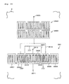
- FIG. 2 illustrates the essential configuration of a SAW apparatus of a first comparative example.
- FIG. 3 is a schematic diagram illustrating a SAW apparatus according to a modification of the first preferred embodiment of the present invention.
- FIG. 4 is a schematic diagram illustrating a weighted area of the SAW apparatus of the first preferred embodiment of the present invention.
- FIG. 5 is a graph illustrating the amplitude balance level (amplitude balance) of the SAW apparatus of the first preferred embodiment of the present invention.
- FIG. 6 is a graph illustrating the phase balance level (phase balance) of the SAW apparatus of the first preferred embodiment of the present invention.
- FIG. 7 is a graph illustrating the amplitude balance level (amplitude balance) of the SAW apparatus of the first comparative example.
- FIG. 8 is a graph illustrating the phase balance level (phase balance) of the SAW apparatus of the first comparative example.
- FIG. 9 is a schematic diagram illustrating another modification made to the first preferred embodiment of the present invention.
- FIG. 10 is a schematic diagram illustrating still another modification made to the first preferred embodiment of the present invention.
- FIG. 11 is a schematic diagram illustrating a further modification made to the first preferred embodiment of the present invention.
- FIG. 12 is a schematic diagram illustrating a further modification made to the first preferred embodiment of the present invention.
- FIG. 13 is a schematic diagram illustrating a further modification made to the first preferred embodiment of the present invention.
- FIG. 14 is a schematic diagram illustrating a further modification made to the first preferred embodiment of the present invention.
- FIG. 15 is a schematic diagram illustrating a further modification made to the first preferred embodiment of the present invention.
- FIG. 16 is a schematic diagram illustrating a further modification made to the first preferred embodiment of the present invention.
- FIG. 17 is a schematic diagram illustrating a further modification made to the first preferred embodiment of the present invention.
- FIG. 18 is a schematic diagram illustrating a further modification made to the first preferred embodiment of the present invention.
- FIG. 19 is a schematic diagram illustrating a further modification made to the first preferred embodiment of the present invention.
- FIG. 20 is a schematic diagram illustrating a further modification made to the first preferred embodiment of the present invention.
- FIG. 21 is a schematic diagram illustrating a further modification made to the first preferred embodiment of the present invention.
- FIG. 22 is a schematic diagram illustrating a further modification made to the first preferred embodiment of the present invention.
- FIG. 23 is a schematic diagram illustrating a further modification made to the first preferred embodiment of the present invention.
- FIG. 24 is schematic diagram illustrating a SAW apparatus according to a second preferred embodiment of the present invention.
- FIG. 25 is a graph illustrating the amplitude balance level (amplitude balance) of the SAW apparatus of the second preferred embodiment of the present invention.
- FIG. 26 is a graph illustrating the phase balance level (phase balance) of the SAW apparatus of the second preferred embodiment of the present invention.
- FIG. 27 is a graph illustrating transmission characteristics of the SAW apparatus of the first preferred embodiment of the present invention.
- FIG. 28 is a graph illustrating transmission characteristics of the SAW apparatus of the second preferred embodiment of the present invention.
- FIG. 29 is a schematic diagram illustrating a SAW apparatus according to a third preferred embodiment of the present invention.
- FIG. 30 is a graph illustrating the amplitude balance level (amplitude balance) of the third preferred embodiment of the present invention and that of a second comparative example.
- FIG. 31 is a graph illustrating the phase balance level (phase balance) of the third preferred embodiment of the present invention and that of the second comparative example.
- FIG. 32 is a schematic diagram illustrating a SAW apparatus of the second comparative example.
- FIG. 33 is a schematic diagram illustrating a SAW apparatus according to a fourth preferred embodiment of the present invention.
- FIG. 34 is a graph illustrating the amplitude balance level (amplitude balance) of the SAW apparatus of the fourth preferred embodiment of the present invention and that of the second comparative example.
- FIG. 35 is a schematic diagram illustrating the reduced balance levels in the second comparative example.
- FIG. 36 is a schematic diagram illustrating the improved balance levels in the fourth preferred embodiment of the present invention.
- FIG. 37 is a schematic diagram illustrating a modification made to the fourth preferred embodiment of the present invention.
- FIG. 38 is a schematic diagram illustrating the improved balance levels in the modification shown in FIG. 37 .
- FIG. 39 is a schematic diagram illustrating another modification made to the fourth preferred embodiment of the present invention.
- FIG. 40 is a schematic diagram illustrating the improved balance levels in the modification shown in FIG. 39 .
- FIG. 41 is a schematic diagram illustrating still another modification made to the fourth preferred embodiment of the present invention.
- FIG. 42 is a schematic diagram illustrating a SAW apparatus according to a fifth preferred embodiment of the present invention.
- FIG. 43 is a graph illustrating the amplitude balance level (amplitude balance) of the fifth preferred embodiment of the present invention and that of a third comparative example.
- FIG. 44 is a schematic diagram illustrating a SAW apparatus of the third comparative example.
- FIG. 45 is a schematic diagram illustrating the reduced balance levels in the third comparative example.
- FIG. 46 is a schematic diagram illustrating the improved balance levels in the fifth preferred embodiment of the present invention.
- FIG. 47 is a schematic diagram illustrating a SAW apparatus according to a sixth preferred embodiment of the present invention.
- FIG. 48 is an enlarged diagram illustrating the SAW apparatus shown in FIG. 47 .
- FIG. 49 is a graph illustrating the amplitude balance level (amplitude balance) of the sixth preferred embodiment of the present invention and that of a fourth comparative example.
- FIG. 50 is a schematic diagram illustrating a SAW apparatus of the fourth comparative example.
- FIG. 51 is a graph illustrating a change in the amplitude balance level (amplitude balance) by varying the interdigital length in the SAW apparatus of the sixth preferred embodiment of the present invention.
- FIG. 52 is a schematic diagram illustrating a SAW apparatus of a modification made to the sixth preferred embodiment of the present invention.
- FIG. 53 is a schematic diagram illustrating a SAW apparatus of another modification made to the sixth preferred embodiment of the present invention.
- FIG. 54 is a schematic diagram illustrating a SAW apparatus of still another modification made to the sixth preferred embodiment of the present invention.
- FIG. 55 is a schematic diagram illustrating a SAW apparatus according to a seventh preferred embodiment of the present invention.
- FIG. 56 is a graph illustrating the amplitude balance level (amplitude balance) of the seventh preferred embodiment of the present invention and that of the second comparative example.
- FIG. 57 is a graph illustrating the phase balance level (phase balance) of the seventh preferred embodiment of the present invention and that of the second comparative example.
- FIG. 58 is a schematic diagram illustrating a modification made to the seventh preferred embodiment of the present invention.
- FIG. 59 is a schematic diagram illustrating another modification made to the seventh preferred embodiment of the present invention.
- FIG. 60 is a graph illustrating the amplitude balance level (amplitude balance) of the modification shown in FIG. 59 and that of the second comparative example.
- FIG. 61 is a graph illustrating the phase balance level (phase balance) of the modification shown in FIG. 59 and that of the second comparative example.
- FIG. 62 is a schematic diagram illustrating a SAW apparatus according to an eighth preferred embodiment of the present invention.
- FIG. 63 is a graph illustrating the amplitude balance level (amplitude balance) of the eighth preferred embodiment of the present invention and that of the second comparative example.
- FIG. 64 is a graph illustrating the phase balance level (phase balance) of the eighth preferred embodiment of the present invention and that of the second comparative example.
- FIG. 65 is a schematic diagram illustrating a SAW apparatus according to a ninth preferred embodiment of the present invention.
- FIG. 66 is a schematic block diagram illustrating a communication unit according to a preferred embodiment of the present invention.
- FIG. 67 is a schematic diagram illustrating the SAW apparatus of the first comparative example.
- FIG. 68 is a schematic diagram illustrating the SAW apparatus of the second comparative example.
- FIG. 69 is a graph illustrating a difference in insertion loss between balanced signal terminals of a known SAW apparatus.
- FIGS. 70 and 71 are schematic diagrams illustrating a difference in insertion loss between the balanced signal terminals of the known SAW apparatus.
- FIGS. 72A and 72B illustrate resonance modes in a SAW apparatus: FIG. 72A is a graph illustrating the frequency of the resonance modes; and FIG. 72B illustrates the current distribution of the resonance modes.
- FIG. 73 is a schematic diagram illustrating the SAW apparatus of the third comparative example.
- FIGS. 1 through 66 through illustration of preferred embodiments.
- FIG. 1 illustrates a SAW apparatus constructed in accordance with a first preferred embodiment of the present invention.
- the SAW apparatus shown in FIG. 1 has an unbalanced-to-balanced conversion function and a filtering function, and includes an input IDT 1 , output IDTs 2 and 3 provided on the left and right sides of the input IDT 1 (along a SAW propagating direction), and reflectors 4 provided outside the output IDTs 2 and 3 on a piezoelectric substrate 8 .
- the input side and the output side are interchangeable.
- the output IDTs 2 and 3 are arranged such that they sandwich the input IDT 1 therebetween.
- the reflectors 4 are arranged such that they sandwich the IDTs 2 , 1 , and 3 therebetween, to reflect a propagating SAW.
- the piezoelectric substrate 8 is made of, for example, a 40 ⁇ 5° Y-cut X-propagating LiTaO 3 , although other substrates may also be used.
- Each of the IDTs 1 , 2 , and 3 includes a strip-shaped base portion (bus bar) and two electrode portions provided with a plurality of strip-shaped electrode fingers.
- the electrode fingers extend substantially perpendicularly from one side of the base portion such that they are substantially parallel to each other with substantially uniform gaps disposed therebetween.
- the electrode fingers also interdigitate with each other such that the sides thereof face each other.
- the signal conversion characteristics and the pass band are determined by setting the length and the width of each electrode finger, the pitch between adjacent electrode fingers, and the length by which the interdigitated electrode fingers face each other (hereinafter referred to as the “interdigital length”).
- the number of electrode fingers of the IDT 1 is 39
- the number of electrode fingers of each IDT 2 or 3 is 23.
- the electrode fingers, the bus bars, and the reflectors 4 are made of, for example, an aluminum (Al) electrode (foil), formed on the piezoelectric substrate 8 by, for example, a photolithographic technique or other suitable process.
- Al aluminum
- signal electrode fingers 11 connected to an unbalanced input terminal 5 and ground electrode fingers 12 are interdigitated with each other as described above.
- the ground electrode fingers 12 are arranged such that the outermost electrode fingers, which are located at both ends in a SAW propagating direction, of the IDT 1 define ground electrode fingers 12 .
- the outermost electrode fingers are arranged to face one of the outermost electrode fingers of the IDT 2 and one of the outermost electrode fingers of the IDT 3 .
- signal electrode fingers 22 connected to a balanced output terminal 6 and ground electrode fingers 21 are interdigitated with each other as described above.
- a bus bar 23 connected to the ground electrode fingers 21 is substantially aligned with a bus bar 13 connected to the signal electrode fingers 11 of the input IDT 1 .
- the outermost electrode fingers of the IDT 2 which are arranged at both ends in a SAW propagating direction, define the ground electrodes 21 .
- signal electrode fingers 32 connected to a balanced output terminal 7 and ground electrode fingers 31 are interdigitated with each other as described above.
- a bus bar 33 connected to the ground electrode fingers 31 is substantially aligned with the bus bar 13 connected to the signal electrode fingers 11 of the input IDT 1 .
- a bus bar 14 connected to the ground electrode fingers 12 of the IDT 1 is substantially aligned with a bus bar 24 of the signal electrode fingers 22 of the IDT 2 and to a bus bar 34 of the signal electrode fingers 32 of the IDT 3 .
- the output IDTs 2 and 3 are structurally inverted with respect to each other. More specifically, in the IDT 2 , the ground electrode fingers 21 and the signal electrodes 22 are alternately arranged, such as a ground electrode finger, a signal electrode finger, a ground electrode finger, and so on, starting from the electrode finger adjacent to the IDT 1 . In contrast, in the IDT 3 , the signal electrode fingers 32 and the ground electrode 31 fingers are alternately arranged, such as a signal electrode finger, a ground electrode finger, a signal electrode finger, and so on, starting from the electrode finger adjacent to the IDT 1 .
- the SAW apparatus performs a balanced-to-unbalanced conversion function.
- withdrawal weighting is applied to the outermost electrode finger of the IDT 3 adjacent to the IDT 1 .
- a ground dummy electrode 31 a is provided at a location at which the outermost electrode finger is withdrawal-weighted.
- withdrawal weighting means that an electrode finger is withdrawn, and another electrode finger is replaced. Accordingly, two ground electrodes, i.e., the dummy electrode 31 a and a ground electrode finger 31 b, are sequentially arranged in the IDT 3 adjacent to the IDT 1 .
- an apodization-weighted electrode finger 22 a is provided at the location at which the signal electrode finger 22 next to the ground electrode finger 21 (outermost electrode finger) adjacent to the input IDT 1 is located.
- apodization weighting means that the interdigital length of an electrode finger is changed.
- the length of the apodization-weighted electrode finger 22 a is about one half the length of the other signal electrode fingers 22 . That is, the interdigital length is adjusted.
- a strip-shaped dummy electrode, which is an offset electrode finger, (first balance electrode finger) 21 a extending from the grounded bus bar 23 is provided to fill in a space generated by the apodization-weighted electrode finger 22 a .
- the dummy electrode 21 a extends toward the forward end of the apodization-weighted electrode finger 22 a such that it is substantially parallel to the adjacent ground electrode fingers 21 with substantially uniform gaps disposed therebetween.
- FIG. 2 the schematic configuration of IDTs, which are not withdrawal-weighted or apodization-weighted, of a SAW apparatus having a balanced-to-unbalanced conversion function is shown in FIG. 2 as a first comparative example.
- ground electrode fingers are provided between the IDT 1 and an IDT 40
- a signal electrode finger and a ground electrode finger are provided between the IDT 1 and an IDT 41 .
- a no-electric-field portion 9 in which the conversion between an electrical signal and a SAW is not performed is provided between the IDT 1 and the IDT 40 .
- the conversion between an electrical signal and a SAW is performed between the IDTs 1 and 41 .
- the frequency and the amplitude level of a signal output from the balanced signal terminal 6 is different from those of a signal output from the balanced signal terminal 7 .
- the signals output from the balanced signal terminals 6 and 7 are not substantially 180° out of phase with each other. As a result, the balance levels between the balanced signal terminals 6 and 7 are reduced.
- the signal electrode finger of the IDT 41 adjacent to the ground electrode of the IDT 1 is withdrawal-weighted, as shown in FIG. 3, and the dummy electrode 31 a is provided at the position in which the signal electrode finger is withdrawal-weighted. That is, the two ground electrode fingers are provided in the IDT 3 adjacent to the IDT 1 . Accordingly, a difference of the conversion efficiency between an electrical signal and a SAW between the IDTs 1 and 3 and the IDTs 1 and 40 is offset. Thus, a SAW apparatus having greatly improved balance levels between the balanced signal terminals 6 and 7 is provided.
- the provision of the dummy electrode 31 a also prevents an increase in the loss caused by converting a SAW into a bulk wave. Thus, a SAW apparatus having very low insertion loss within the pass band is provided.
- the dummy electrode 31 a does not have to be grounded, and may be a floating electrode. In this case, however, the balance levels between the balanced signal terminals 6 and 7 are slightly reduced. Thus, the electrode 31 a is preferably grounded.
- the no-electric-field portion 9 provided in the IDTs 1 and 3 is larger than that provided in the IDTs 1 and 40 . Accordingly, sufficient balance levels between the balanced signal terminal 6 and 7 are not obtained.
- the apodization-weighted electrode finger 22 a is provided, as shown in FIG. 4, at the position in which the signal electrode finger 22 adjacent to the outermost electrode finger 21 is located, and the dummy electrode 21 a is also provided. Accordingly, the size of the no-electric-field portion 9 in a boundary area X 1 between the IDTs 1 and 2 is substantially equal to that in a boundary area X 2 between the IDTs 1 and 3 .
- a SAW apparatus having further improved balance levels between the balanced signal terminals 6 and 7 is provided.
- the dummy electrode 21 a also prevents an increase in the loss caused by converting a SAW into a bulk wave. Thus, a SAW apparatus having very low insertion loss within the pass band is provided.
- the grounded dummy electrodes 21 a and 31 a define the no-electric-field portions 9 with the adjacent ground electrode fingers 21 and 31 b, respectively. Accordingly, the size of the no-electric-field portion 9 (an area in which the capacitance is formed) is controlled by providing the dummy electrodes 21 a and 31 a , which is discussed in detail below.
- apodization weighting since a smaller weight is required for the signal electrode fingers, the no-electric-field portion 9 is adjusted more efficiently by weighting the signal electrode fingers.
- apodization weighting may be applied to the ground electrodes.
- a weight is applied to the outermost electrode finger of the IDT 3
- a weight is applied to the electrode finger adjacent to the outermost electrode finger of the IDT 2
- a weight may be applied to any electrode finger.
- the current is most sharply changed at the electrode fingers between the adjacent IDTs, as shown in FIG. 72 B.
- it is more effective, as shown in FIG. 4, to apply the weight within a range of about 1 ⁇ 2 of the SAW propagation length “a” in the IDT 2 from the outermost electrode finger adjacent to the IDT 1 .
- apodization weighting is performed by providing the apodization-weighted electrode finger 22 a , having a length that is about one half the signal electrode finger 22 .
- the amount apodization weighting may be adjusted as required.
- the signal electrode finger 22 close to the IDT 1 may be apodization-weighted by about one fourth, and the subsequent signal electrode finger 22 may be apodization-weighted by about one fourth. In this case, advantages similar to those obtained by the first preferred embodiment are achieved.
- the amplitude balance level and the phase balance level between the balanced signal terminals 6 and 7 with respect to the frequency obtained by the first preferred embodiment are shown in FIGS. 5 and 6, respectively.
- the amplitude balance level and the phase balance level between the balanced signal terminals 6 and 7 with respect to the frequency in the first comparative example shown in FIG. 2 are shown in FIGS. 7 and 8, respectively.
- the frequency range of the pass band for Extended Global System for Mobile Communication (EGSM) transmission filters is 880 MHz to 915 MHz.
- the amplitude balance level between the balanced signal terminals 6 and 7 with respect the above-mentioned frequency range ranges from ⁇ 1.6 dB to +1.5 dB (having a deviation of 3.1 dB) for the first comparative example, while the corresponding amplitude balance level ranges from about ⁇ 0.7 dB to about +1.2 dB (having a deviation of 1.9 dB) for the first preferred embodiment.
- the level of the amplitude balance level is greatly improved with a reduced deviation.
- the amplitude balance level is improved by about 1.2 dB.
- phase balance level between the balanced signal terminals 6 and 7 for the first comparative example ranges from 172° to 189° (having a deviation of 17°), while the corresponding phase balance for the first preferred embodiment ranges from 178° to 184° (having a deviation of 6°).
- the level of the phase balance level is greatly improved with a reduced deviation.
- the phase balance level is improved by about 11°.
- weighting is applied to the SAW apparatus having the balanced-to-unbalanced conversion function by using a single longitudinally-coupled-resonator-type SAW filter device.
- a SAW apparatus having greatly improved balance levels between the balanced signal terminals 6 and 7 over known SAW apparatuses is provided.
- a single three-IDT-type longitudinally-coupled-resonator-type SAW filter device is used.
- the present invention is not restricted to this configuration, and the SAW apparatus may be configured in any manner as long as it is provided with the balanced signal terminals 6 and 7 . In this case, advantages similar to those obtained by the first preferred embodiment can be achieved.
- FIG. 9 illustrates a SAW apparatus having a balanced-to-unbalanced conversion function using a longitudinally-coupled-resonator-type SAW filter having five IDTs (balanced signal terminals 401 and 402 , and an unbalanced signal terminal 403 ).
- a SAW apparatus using a longitudinally-coupled-resonator-type SAW filter having more than three-IDTs or having two IDTs the same advantages of the present invention are achieved.
- the type of filter used in the present invention is not limited to a longitudinally-coupled-resonator-type SAW filter, and a transversal SAW filter or a length-coupled-resonator-mode SAW filter may be provided, in which case, advantages similar to those obtained by the first preferred embodiment are achieved.
- the SAW apparatus is provided with a balanced-to-unbalanced conversion function.
- a balanced signal may be input and a balanced signal may be output. More specifically, in FIG. 10, balanced signal terminals 501 and 502 define a pair, and balanced signal terminals 503 and 504 define a pair. In FIG. 11, balanced signal terminals 601 and 602 define a pair, and balanced signal terminals 603 and 604 define a pair. In this case, advantages similar to those obtained by the first preferred embodiment are achieved.
- the SAW apparatus having a balanced-to-unbalanced conversion function is configured to include a single longitudinally-coupled-resonator-type filter.
- the present invention is not restricted to this type of configuration.
- balanced signal terminals 701 and 702 may be connected to comb-like electrodes of a single IDT in a single longitudinally-coupled-resonator-type SAW filter.
- reference numeral 703 indicates an unbalanced signal terminal.
- one IDT is divided in the direction of the interdigital length so as to change the impedance.
- reference numerals 801 and 802 indicate balanced signal terminals, and reference numeral 803 indicates an unbalanced signal terminal.
- FIG. 14 one IDT is divided in a SAW propagating direction, and balanced signal terminals 901 and 902 are connected to the divided comb-like electrodes.
- reference numeral 903 designates an unbalanced signal terminal.
- an unbalanced signal terminal 1003 is connected to inverted comb-like electrodes of IDTs on the left and right sides.
- a SAW apparatus having an improved attenuation outside the pass band is provided.
- reference numerals 1001 and 1002 designate balanced signal terminals.
- a plurality of longitudinally-coupled-resonator-type SAW filters may be combined to define a SAW apparatus having a balanced-to-unbalanced conversion function. In this case, advantages similar to those obtained by the first preferred embodiment are achieved.
- two longitudinally-coupled-resonator-type SAW filters 1104 and 1105 are provided such that output signals from the SAW filters 1104 and 1105 are about 180° out of phase with each other.
- IDTs connected to balanced signal terminals 1101 and 1102 are connected in series to each other, and IDTs connected to an unbalanced signal terminal 1103 are connected in parallel to each other.
- a single longitudinally-coupled-resonator-type SAW filter 1201 is cascade-connected to the configuration shown in FIG. 16 .
- weights are applied to the configuration shown in FIG. 68 .
- IDTs 1303 and 1304 are inverted with respect to each other such that electrical signals transmitting in signal lines 1301 and 1302 used for cascade-connecting two longitudinally-coupled-resonator-type SAW filters are about 180° out of phase with each other.
- IDTs 1307 and 1308 may be inverted with respect to each other such that electrical signals transmitting in signal lines 1305 and 1306 are about 180° out of phase with each other.
- a single longitudinally-coupled-resonator-type SAW filter 1401 is cascade-connected to the SAW apparatus shown in FIG. 12, in which case, advantages similar to those obtained by the first preferred embodiment are achieved.
- a SAW apparatus having not only improved balance levels between balanced signal terminals, but also an increased attenuation outside the pass band is obtained.
- IDTs 1503 and 1504 are inverted with respect to each other such that electrical signals transmitting in signal lines 1501 and 1502 are about 180° out of phase with each other, as in the configuration shown in FIG. 19 .
- a SAW apparatus having further improved balance levels between balanced signal terminals is provided.
- the same type of longitudinally-coupled-resonator-type SAW filter is not necessarily used.
- the interdigital length may be different between SAW filters.
- the number of pairs of electrode fingers of an IDT, the center-to-center distance between adjacent IDTs, or the center-to-center distance between an IDT and a reflector may be different between SAW filters. Accordingly, different designs of SAW filters may be used.
- the total number of electrode fingers of each IDT is preferably an odd number
- the total number of electrode fingers may be an even number.
- the total number of electrode fingers of the central IDT connected to balanced signal terminals is preferably an even number.
- the horizontal symmetrical characteristics with respect to the center of the longitudinally-coupled-resonator-type SAW filter is greatly improved, and the number of electrode fingers connected to one balanced signal terminal is equal to that connected to the other balanced signal terminal.
- a SAW apparatus having further improved balance levels between balanced signal terminals is provided.
- SAW resonators 1601 and 1602 are connected in series to each other.
- SAW resonators may be connected in parallel to each other.
- series-connected SAW resonators and parallel-connected SAW resonators may be connected to each other. In this case, a SAW apparatus having not only improved balance levels between balanced signal terminals, but also an increased attenuation in a range in the vicinity of the pass band is obtained.
- FIGS. 24 through 28 A second preferred embodiment of the present invention is described below with reference to FIGS. 24 through 28.
- components having functions similar to those of the SAW apparatus shown in FIG. 1 are indicated by like reference numerals, and an explanation thereof is thus omitted.
- series weighting is applied, as shown in FIG. 24 . That is, an IDT 25 is substituted for the IDT 2 used in the first preferred embodiment.
- an apodization-weighted electrode finger 21 b which is arranged subsequent to the apodization-weighted electrode finger 22 a and is shorter than in the apodization-weighted electrode finger 22 a .
- a dummy electrode finger (second balance electrode finger) 25 a is arranged such that it is separated from the apodization-weighted electrode fingers 22 a and 21 b (i.e., the dummy electrode finger 25 a is floating).
- the dummy electrode finger 25 a is preferably substantially the same length as the apodization-weighted electrode finger 22 a between and substantially in parallel to the apodization-weighted electrode finger 22 a and the subsequent signal electrode finger 22 , passes between the forward end of the apodization-weighted electrode finger 22 a and the forward end of the apodization-weighted electrode finger 21 b, and is extended between and substantially in parallel to the apodization-weighted electrode finger 21 b and the outermost ground electrode finger 21 .
- FIGS. 25 and 26 show that the amplitude balance level between the balanced signal terminals in a frequency range of the pass band used for EGSM transmission filters ranges from ⁇ 0.7 dB to +1.2 dB (having a deviation of 1.9 dB), which is the same result as the first preferred embodiment.
- FIG. 26 shows that the phase balance level between the balanced signal terminals ranges from 177° to 182° (having a deviation of 5°). Accordingly, the balance level is improved over the first preferred embodiment by 1°.
- the transmission characteristics within the pass band with respect to the frequency obtained by the first preferred embodiment are shown in FIG. 27, and the transmission characteristics within the pass band with respect to the frequency obtained by the second preferred embodiment are shown in FIG. 28 .
- ripple A is generated (see FIG. 27) within the pass band in the first preferred embodiment, while ripple A is not generated (see FIG. 28) within the pass band in the second preferred embodiment.
- the deviation is smaller within the pass band.
- the generation of ripples is prevented in the transmission characteristics, and thus, the SAW apparatus of the second preferred embodiment exhibits further improved transmission characteristics.
- FIG. 29 illustrates a SAW apparatus according to the third preferred embodiment of the present invention.
- the present invention is described with reference to a PCS receiving filter.
- a three-IDT-type longitudinally-coupled-resonator-type SAW filter 201 , and SAW resonators 202 and 203 , which are connected in series to the SAW filter 201 are preferably formed of an Al electrode (foil) by, for example, a photolithographic technique or other suitable process.
- the piezoelectric substrate 200 is preferably a 40 ⁇ 5° Y-cut X-propagating LiTaO 3 although other substrates may be used.
- the SAW filter 201 is substantially the same as that shown in FIG. 10 .
- IDTs 204 and 206 are arranged such that they sandwich a central IDT 205 , which is connected to balanced signal terminals 210 and 211 , from the left and right sides (along a SAW propagating direction).
- Reflectors 207 and 208 which reflect SAWs from the IDTs 204 , 205 , and 206 , are provided outside the IDTs 204 and 206 , respectively (along a SAW propagating direction). That is, the IDTs 204 , 205 , and 206 and the reflectors 207 and 208 are arranged on the SAW propagation path such that the lengths of the electrode fingers are substantially parallel to the SAW propagating direction.
- the pitch between some electrode fingers in a portion (indicated by 213 in FIG. 29) between the adjacent IDTs 204 and 205 , and the pitch between some electrode fingers in a portion (indicated by 214 in FIG. 29) between the adjacent IDTs 204 and 206 are narrower than the pitch between the other electrode fingers.
- reference numeral 209 designates an unbalanced signal terminal. Accordingly, the IDTs 204 and 206 are connected to the unbalanced signal terminal 209 .
- the IDT 204 includes signal electrode fingers 204 a and ground electrode fingers 204 b, and the IDT 206 includes signal electrode fingers 206 a and ground electrode fingers 206 b.
- the IDT 205 is connected to the balanced signal terminals 210 and 211 , and includes signal electrode fingers 205 a and 205 b .
- weighting is applied to a SAW apparatus which does not include an electrical neutral point.
- the SAW resonators 202 and 203 are connected between and in series to the unbalanced signal terminal 209 and the IDTs 204 and 206 via a signal line 212 .
- the SAW resonator 202 includes an IDT 202 a , and reflectors 202 b and 202 c which are arranged such that they sandwich the IDT 202 a along a SAW propagating direction.
- the SAW resonator 203 includes an IDT 203 a, and reflectors 203 b and 203 c which are arranged such that they sandwich the IDT 203 a along a SAW propagating direction.
- the features of the third preferred embodiment are as follows. Withdrawal weighting is applied to an electrode finger 219 of the IDT 206 adjacent to the IDT 205 . Additionally, the signal electrode finger 206 a of the IDT 206 adjacent to the IDT 205 is withdrawal-weighted.
- the interdigital length, the pitch, the duty, and the width of the electrode finger 219 are preferably substantially the same as those of the narrower-pitch ground electrode fingers 206 b.
- a plurality of (for example, two) ground electrode fingers 206 b is sequentially provided at the portion adjacent to the IDT 205 .
- interdigital length W 60 . 6 ⁇ I 1 ;
- IDT wavelength ⁇ I 1 2.06 ⁇ m
- IDT wavelength ⁇ I 2 1.88 ⁇ m
- IDT pitch 0.50 ⁇ I 2 ;
- pitch between wider pitch electrode finger ( ⁇ I 1 ) and narrower-pitch electrode finger ( ⁇ I 2 ) (indicated by 215 , 216 , 217 , and 218 ): 0.25 ⁇ I 1 +0.25 ⁇ I 2 ;
- wavelength ⁇ (for IDT and reflectors): 1.97 ⁇ m;
- wavelength ⁇ (for IDT and reflectors): 2.04 ⁇ m;
- the characteristics of the third preferred embodiment were measured, and the results are shown in FIGS. 30 and 31. More specifically, the amplitude balance level between the balanced signal terminals with respect to the frequency obtained by the third preferred embodiment is shown in FIG. 30, and the phase balance level obtained by the third preferred embodiment are shown in FIG. 31 .
- FIGS. 30 and 31 the amplitude balance level and the phase balance level of a SAW filter having an IDT 206 c shown in FIG. 32 instead of the IDT 206 are shown FIGS. 30 and 31 as a second comparative example.
- withdrawal weighting is not provided at the portion between two adjacent IDTs.
- the configuration of the SAW apparatus of the second comparative example is the same as that of the third preferred embodiment, except that the IDT 206 c, which is not withdrawal-weighted, is used instead of the IDT 206 .
- the frequency range of the pass band used for PCS receiving filters is 1930 MHz to 1990 MHz.
- the maximum amplitude balance level in this range of the second comparative example ranges form ⁇ 1.6 dB to +0.7 dB (having a deviation of 2.3 dB).
- the maximum amplitude balance level of the third preferred embodiment ranges from ⁇ 1.5 dB to +0.7 dB (having a deviation of 2.2 dB). Accordingly, the amplitude balance level is improved by about 0.1 dB.
- the phase balance level of the second comparative example ranges from 162° to 182° (having a deviation of 20°), while the phase balance level of the third preferred embodiment ranges from 162° to 181° (having a deviation of 19°). Accordingly, the phase balance level is improved by about 1°.
- the balance levels of the third preferred embodiment are improved over the second comparative example.
- the reason for this is as follows.
- the polarities between the IDTs 206 and 205 are the same (positive), i.e., signal electrode fingers are provided between the IDTs 206 and 205 .
- the polarities between the IDTs 206 and 205 are negative and positive, as in the polarities between the IDTs 204 and 205 .
- symmetrical characteristics of the SAW filter are improved in the third preferred embodiment.
- the electrode fingers provided at the portion between two adjacent IDTs are withdrawal-weighted.
- a SAW filter having improved balance levels between balanced signal terminals over known SAW filters is obtained.
- a fourth preferred embodiment of the present invention is described in detail below with reference to FIGS. 33 through 41.
- the present invention is discussed in the context of an EGSM receiving filter.
- a SAW apparatus includes two longitudinally-coupled-resonator-type SAW filters 1918 and 1920 , having output signals that are about 180° out of phase with each other.
- One terminal of the SAW filter 1918 and one terminal of the SAW filter 1920 are connected in parallel to each other so as to define an unbalanced signal terminal 1905
- the other terminals of the SAW filters 1918 and 1920 are connected in series to each other so as to define balanced signal terminals 1906 and 1907 .
- the SAW apparatus is provided with a balanced-to-unbalanced conversion function.
- an extra longitudinally-coupled-resonator-type SAW filter 1918 is cascade-connected to each of the SAW filters 1918 and 1920 , respectively. Withdrawal weighting is applied to the SAW filter 1920 by providing a dummy electrode 1901 b.
- the four longitudinally-coupled-resonator-type SAW filters 1918 and 1920 are preferably defined by AL electrodes provided on a piezoelectric substrate 8 .
- the four SAW filters 1918 and 1920 are designed similarly, except that the output signals from the SAW filters 1918 and the output signal from the SAW filter 1920 are about 180° out of phase with each other, and that the SAW filter 1920 is withdrawal-weighted.
- a few narrower-pitch electrode fingers are provided between two adjacent IDTs.
- the configuration of the fourth preferred embodiment is similar to that of the second comparative example shown in FIG. 68, except for weighting.
- IDT wavelength ⁇ I 1 4.204 ⁇ m
- IDT wavelength ⁇ I 2 3.854 ⁇ m
- ⁇ I 2 (indicated by 215 , 216 , 217 , and 218 ): 0.25 ⁇ I 1 +0.25 ⁇ I 2 ;
- the fourth preferred embodiment includes the dummy electrode 1901 b. More specifically, in order to invert the phase of an output signal from the SAW filter 1920 from that of the SAW filter 1918 , the direction of an IDT 1901 a of the SAW filter 1920 is inverted with respect to the IDT 1901 of the SAW filter 1918 . One side of the IDT 1901 a is withdrawal-weighted, and the dummy electrode 1901 b is then provided in the weighted portion and is grounded.
- the amplitude balance level between balanced signal terminals 1906 and 1907 with respect to the frequency obtained by the fourth preferred embodiment is shown in FIG. 34 .
- the amplitude balance level between the balanced signal terminals with respect to the frequency in the second comparative example shown in FIG. 68 is also shown in FIG. 34 .
- the configuration of the second comparative example is the same as that of the fourth preferred embodiment, except that withdrawal-weighting is not applied to the second comparative example.
- the frequency range in the pass band used for EGSM receiving filters is 925 MHz to 960 MHz.
- the amplitude balance level between the balanced signal terminals in the second comparative example ranges from ⁇ 0.2 dB to +1.3 dB (having a deviation of 1.5 dB).
- the amplitude balance level obtained by the fourth preferred embodiment ranges from ⁇ 0.7 dB to +0.2 dB (having a deviation of 0.9 dB). Accordingly, the amplitude balance level is improved by about 0.6 dB.
- a SAW is excited between adjacent electrode fingers having different polarities.
- the excitation state of SAWs in the portions between adjacent IDTs of the SAW filters 118 and 127 (indicated by 125 and 126 in FIG. 68) shown in FIG. 68 is shown in FIG. 35 .
- the SAW filters 118 and 127 shown in FIG. 68 correspond to longitudinally-coupled-resonator-type SAW filters 2007 and 2008 , respectively, shown in FIG. 35 .
- the IDTs 113 , 114 , and 115 shown in FIG. 68 correspond to IDTs 2001 , 2002 , and 2003 , respectively, shown in FIG. 35 .
- the IDTs 133 , 134 , and 135 shown in FIG. 68 correspond to IDTs 2004 , 2005 , and 2006 , respectively, shown in FIG. 35 .
- a SAW is excited in portions indicated by the circle, and a SAW is not excited in portions indicated by the cross (x).
- the outermost electrode fingers of the IDT 2004 are signal electrode fingers, and the outermost electrode fingers of the IDTs 2005 and 2006 are ground electrodes.
- a SAW is excited between adjacent electrode fingers of the IDTs 2004 , 2005 , and 2006 , and thus, a SAW is excited in two additional portions of the SAW filter 2008 than those of the SAW filter 2007 .
- the intensity distribution of the effective current of a SAW between adjacent electrode fingers is different between the SAW filters 2007 and 2008 .
- the period between the central resonance mode B and the highest-frequency resonance mode C is different between the SAW filters 2007 and 2008 , thereby reducing the balance level between the balanced signal terminals.
- FIG. 36 illustrates the SAW excitation state in the portions between adjacent IDTs (indicated by elliptic shapes in FIG. 33) in the SAW filters 1918 and 1920 shown in FIG. 33 .
- FIG. 35 in FIG. 36, only three electrode fingers from the edge of each IDT adjacent to another IDT are shown, and the other electrode fingers are omitted.
- the SAW filters 1918 and 1920 shown in FIG. 33 correspond to SAW filters 2107 and 2108 , respectively.
- the IDTs 1902 , 1901 , and 1903 of the SAW filter 1918 shown in FIG. 33 correspond to IDTs 2102 , 2101 , and 2103 , respectively, shown in FIG. 36 .
- the IDTs 1901 a , 1902 , and 1903 shown in FIG. 33 correspond to IDTs 2104 , 2105 , and 2106 , respectively, shown in FIG. 36 .
- an output signal from the SAW filter 2107 is about 180° out of phase with that from the SAW filter 2108 .
- the outermost electrode finger of the IDT 2104 is withdrawal-weighted, and a dummy electrode finger 2109 (the dummy electrode 1901 b in FIG. 33) is then disposed in the weighted portion and is grounded.
- signal electrode fingers and ground electrode fingers are alternately provided in a portion 2110 between the IDTs 2104 and 2105 , and thus, a SAW is excited.
- three ground electrode fingers are sequentially disposed in a portion 2111 between two adjacent IDTs 2104 and 2106 , and thus, a SAW is not excited in two portions.
- the total number of portions in which a SAW is not excited in the SAW filter 2107 is the same as that in the SAW filter 2108 .
- the total number of portions in which a SAW is excited in the SAW filter 2107 is equal to that in the SAW filter 2108 .
- the period of appearance of the resonance modes is less than that of the second comparative example, thereby improving the amplitude balance level between the balanced signal terminals.
- a SAW apparatus shown in FIG. 37 includes a first longitudinally-coupled-resonator-type SAW filter unit 2202 and a second longitudinally-coupled-resonator-type SAW filter unit 2204 .
- the first SAW filter unit 2202 is preferably defined by cascade-connecting two longitudinally-coupled-resonator-type SAW filters 2201 .
- the second SAW filter unit 2202 is preferably defined by cascade-connecting the longitudinally-coupled-resonator-type SAW filter 2201 and a longitudinally-coupled-resonator-type SAW filter 2201 a.
- the direction of an IDT 2203 of the SAW filter 2201 a is inverted with respect to that of the corresponding IDT of the SAW filter 2201 .
- an output signal from the SAW filter unit 2202 is about 180° out of phase with an output signal from the SAW filter unit 2204 .
- the central IDTs of the first stage of SAW filters 2201 are connected in parallel to each other to define an unbalanced signal terminal 2205 .
- the central IDTs of the second stage of the SAW filters 2201 and 2201 a are connected in series to each other so as to define balanced signal terminals 2206 .
- the outermost electrode finger of the IDT 2203 is withdrawal-weighted, and a dummy electrode 2207 is provided in the weighted portion and is grounded.
- the SAW excitation state in the portion between two adjacent IDTs (indicated by the elliptical shapes in FIG. 37) in the first and second SAW filter units 2202 and 2204 connected to the balanced signal terminals 2206 is shown in FIG. 38 .
- the total number of portions between electrode fingers in which a SAW is not excited in the SAW filter unit 2202 is equal to that in the SAW filter unit 2204 .
- the amplitude balance level between the balanced signal terminals 2206 is improved.
- an output signal from a first SAW filter unit 2303 is about 180° out of phase with an output signal from a second SAW filter unit 2304 .
- the outermost electrode finger of an inverted IDT 2301 is withdrawal-weighted, and a dummy electrode 2302 is provided in the weighted portion and is grounded.
- the SAW excitation state of the portions between two adjacent IDTs (indicated by the elliptical shapes in FIG. 39) in the SAW filter connected to the balanced signal terminals is shown in FIG. 40 .
- the total number of portions between electrode fingers in which a SAW is not excited in the first SAW filter unit 2303 is equal to that in the second SAW filter unit 2304 .
- the amplitude balance level between the balanced signal terminals is greatly improved.
- five-IDT-type longitudinally-coupled-resonator-type filters may be used, as shown in FIG. 41 .
- one of the outermost electrode fingers of an inverted IDT 2401 is withdrawal-weighted, and a dummy electrode finger 2402 is provided in the weighted portion and is grounded.
- the total number of portions between electrode fingers in which a SAW is not excited in a first SAW filter unit 2403 is the same as that in a second SAW filter unit 2404 .
- the amplitude balance level between the balanced signal terminals is greatly improved.
- two SAW filters having output signals that are about 180° out of phase with each other, and one signal terminal of one SAW filter and one signal terminal of the other SAW filter are connected in series to each other to define balanced signal terminals, while the other signal terminals of the two SAW filters are connected in parallel to each other to define an unbalanced signal terminal.
- the SAW apparatus is provided with a balanced-to-unbalanced conversion function.
- an additional SAW filter is cascade-connected to each of the two SAW filters, and then, withdrawal-weighting is applied to the cascade-connected SAW filter.
- a fifth preferred embodiment of the present invention is discussed below with reference to FIGS. 42 through 46.
- the present invention is described in the context of a Digital Cellular System (DCS) receiving filter.
- DCS Digital Cellular System
- a SAW apparatus according to the fifth preferred embodiment of the present invention is shown in FIG. 42 .
- Two longitudinally-coupled-resonator-type SAW filters having output signals that are about 180° out of phase with each other are provided.
- One terminal of one SAW filter and one terminal of the other SAW filter are connected in series to each other so as to define balanced signal terminals, while the other terminals of the SAW filters are connected in parallel to each other so as to define an unbalanced signal terminal.
- the SAW apparatus is provided with a balanced-to-unbalanced conversion function. Weighting is applied to this configuration.
- longitudinally-coupled-resonator-type SAW filters 2501 and 2508 and SAW resonators 2502 and 2503 are preferably formed by Al electrodes on the above-described piezoelectric substrate 8 .
- the SAW resonators 2502 and 2503 are connected in series to each of the SAW filters 2501 and 2508 .
- the two SAW filters 2501 and 2508 are similar, except that an output signal from the SAW filter 2501 is about 180° out of phase with that from the SAW filter 2508 .
- a few narrower-pitch electrode fingers are provided between two IDTs.
- IDT wavelength ⁇ I 1 2.156 ⁇ m
- IDT wavelength ⁇ I 2 1.926 ⁇ m
- wavelength ⁇ (for IDT and reflectors): 2.102 ⁇ m;
- wavelength ⁇ (for IDT and reflectors): 2.023 ⁇ m;
- the features of the fifth preferred embodiment are as follows. In order to invert the phase of an output signal from the SAW filter 2508 with respect to that from the SAW filter 2501 , the direction of an IDT 2509 of the SAW filter 2508 is inverted, and one of the outermost signal electrode fingers of the IDT 2509 is withdrawal-weighted, and a dummy electrode 2510 is provided in the weighted portion and is grounded. Additionally, the three IDTs are grounded via the dummy electrode 2510 .
- FIG. 43 illustrates the amplitude balance level between the balanced signal terminals with respect to the frequency obtained by the fifth preferred embodiment.
- the amplitude balance level between balanced signal terminals in a third comparative example shown in FIG. 44 is also shown in FIG. 43 .
- the configuration of the third comparative example shown in FIG. 44 is the same as that of the fifth preferred embodiment, except that withdrawal-weighting is not applied to the third comparative example.
- the frequency range of the pass band used for DCS receiving filters is 1805 MHz to 1880 MHz.
- the amplitude balance level between the balanced signal terminals in this range in the third comparative example ranges from ⁇ 1.0 dB to +3.2 dB (having a deviation of 4.2 dB), while the corresponding amplitude balance level obtained by the fifth preferred embodiment ranges from ⁇ 0.5 dB to +1.5 dB (having a deviation of 2.0 dB).
- the amplitude balance level is improved by about 2.2 dB.
- the reason for this is as follows.
- the number of portions between adjacent IDTs in which a SAW is excited (indicated by the elliptical shapes in FIG. 44) in the third comparative example shown in FIG. 44 is different between a first SAW filter 2601 and a second SAW filter 2602 , as shown in FIG. 45 .
- the number of portions between adjacent IDTs in which a SAW is excited is the same between first and second longitudinally-coupled-resonator-type SAW filter unit 2511 and 2512 .
- the period between the central resonance mode B and the highest-frequency resonance mode C between the signals output from the two balanced signal terminals is less than the third comparative example.
- the SAW apparatus includes two longitudinally-coupled-resonator-type SAW filters having output signals that are about 180° out of phase with each other.
- One signal terminal of one SAW filter and one signal terminal of the other SAW filter are connected in series to each other to define balanced signal terminals, and the other signal terminals of the two SAW filters are connected in parallel to each other to define an unbalanced signal terminal.
- the SAW apparatus is provided with a balanced-to-unbalanced conversion function. Withdrawal-weighting is applied to this configuration.
- a SAW apparatus having improved balanced levels between the balanced signal terminals over known SAW apparatuses is obtained.
- the three IDTs including the dummy electrode 2510 are grounded, thereby strengthening the grounding force of the SAW apparatus. Accordingly, the insertion loss within the pass band is decreased, and the attenuation outside the pass band is greatly improved. It is noted that the ground terminal of the central IDT may be omitted.
- a sixth preferred embodiment of the present invention is described below with reference to FIGS. 47 through 54.
- the present invention is discussed in the context of a DCS receiving filter.
- balanced signal terminals 2711 and 2712 are connected to comb-like electrodes of an IDT 2704 of a single longitudinally-coupled-resonator-type SAW filter 2701 . Weighting is then applied to the configuration of a SAW apparatus without an electrical neutral point.
- the longitudinally-coupled-resonator-type SAW filter 2701 , and SAW resonators 2702 and 2703 , which are connected in series to the SAW filter 2701 , are formed by Al electrodes on the above-described piezoelectric substrate 8 .
- the configuration of the SAW filter 2701 is as follows. IDTs 2705 and 2706 are provided on the left and right sides of the IDT 2704 , and reflectors 2707 and 2708 are provided such that they sandwich the IDTs 2705 , 2704 , and 2706 therebetween.
- a few narrower-pitch electrode fingers are provided in portions between two adjacent IDTs (indicated by 2709 and 2710 in FIG. 47 ).
- Reference numeral 2713 designates an unbalanced signal terminal. The enlarged portion between the IDTs 2704 and 2705 is shown in FIG. 48 .
- An outer electrode finger 2704 a of the IDT 2704 connected to the balanced signal terminal 2711 is apodization-weighted, a dummy electrode 2705 a is provided in the weighted portion and is grounded.
- no-apodization-weighted portion (indicated by 2805 in FIG. 48 ): 71.2 ⁇ I 1 ;
- apodization-weighted portion (indicated by 2806 in FIG. 48 : 35.6 ⁇ I 1 ;
- IDT wavelength ⁇ I 1 2.18 ⁇ m
- IDT wavelength ⁇ I 2 1.96 ⁇ m
- electrode finger ( ⁇ I 2 ) (indicated by 2714 in FIG. 47 ): 0.25 ⁇ I 1 +0.25 ⁇ I 2 ;
- narrower-pitch portion 0.60;
- Apodization weighting is applied to the outermost electrode finger of the central IDT 2704 which is adjacent to the ground electrode fingers and which is connected to the balanced signal terminals 2711 so as to define the apodization-weighted electrode fingers 2704 a.
- the dummy electrode 2705 a and a dummy electrode 2706 a are then provided in the apodization-weighted portions, and are grounded.
- the operations and advantages of the sixth preferred embodiment are as follows.
- the amplitude balance level between the balanced signal terminals 2711 and 2712 with respect to the frequency obtained by the sixth preferred embodiment is shown in FIG. 49 .
- the amplitude balance level between balanced signal terminals with respect to the frequency in a fourth comparative example shown in FIG. 50 is also shown in FIG. 49 .
- the configuration of the fourth comparative example is the same as that of the sixth preferred embodiment, except in the configuration of a longitudinally-coupled-resonator-type SAW filter 2701 a, and more specifically, apodization weighting is not applied to outermost electrode fingers of a central IDT.
- the frequency range of the pass band used for DCS receiving filters is 1805 MHz to 1880 MHz.
- the amplitude balance level in this range in the fourth comparative example ranges from ⁇ 1.3 dB to +3.3 dB (having a deviation of 4.6 dB), while the corresponding amplitude balance level obtained by the sixth preferred embodiment ranges from ⁇ 2.0 dB to +1.9 dB (having a deviation of 3.9 dB).
- the amplitude balance level is improved by about 0.7 dB.
- the amplitude balance level deviates considerably toward the positive side, while the deviation of the sixth preferred embodiment is almost equal between the positive side and the negative side. If the amplitude balance level deviates approximately equally between the positive side and the negative side, as in the sixth preferred embodiment, the noise level of an in-phase signal is advantageously reduced. Thus, the sixth preferred embodiment exhibits excellent characteristics as compared to the third comparative example in this respect.
- Apodization weighting is applied to the outermost electrode fingers of the central IDT 2704 , the dummy electrodes 2705 a and 2706 a are then provided in the weighted portions and are grounded.
- the outermost electrode fingers of the IDT 2704 connected to the balanced signal terminals 2711 and 2712 are adjacent to the ground electrode fingers, and thus, the polarities of the outermost electrode fingers between adjacent IDTs are equal in the left and right sides of the SAW apparatus.
- the apodization-weighting optimal value was measured, and the results are given below.
- the ratio of the interdigital length 2806 to which apodization weighting is applied to the interdigital length 2805 to which apodization weighting is not applied hereinafter this ratio is referred to as the “apodization-weighting ratio” was varied, and the a change in the amplitude balance level between the balanced signal terminals within the pass band was determined.
- the apodization-weighting ratio in the configuration shown in FIG. 50 to which apodization weighting is not applied was about 1, and the apodization-weighting ratio in the configuration shown in FIG. 47 was about 1 ⁇ 2.
- the amplitude balance level between the balanced signal terminals was checked by varying the apodization-weighting ratio to about 1 ⁇ 4, about 1 ⁇ 2, and about 3 ⁇ 4. The results are shown in FIG. 51 .
- the amplitude balance level is shown only in the positive side.
- FIG. 51 reveals that the amplitude balance level within the pass band is minimized when the apodization-weighting ratio is about 0.5, i.e., when apodization weighting is applied at the approximate center of the electrode finger.
- the reason for this is as follows.
- the outermost electrode fingers of the central IDT are weighted at the approximate center of the interdigital length, and the weighted electrode fingers are grounded.
- the outermost electrode fingers of the IDT connected to the balanced signal terminals 2711 and 2712 are located adjacent to the ground electrodes by half the interdigital length.
- the polarities of the electrode fingers between adjacent IDTs are equal between the left and right sides of the SAW apparatus.
- the configuration of the sixth preferred embodiment is as follows.
- Balanced signal terminals are connected to comb-like electrodes of an IDT (preferably, the central IDT) of a single longitudinally-coupled-resonator-type SAW filter, and thus, this configuration does not include an electrical neutral point.
- apodization-weighting is applied to the outermost electrode fingers of the central IDT at the approximate center of the interdigital length, and dummy electrodes are then provided in the weighted portions and are grounded.
- a SAW apparatus having a greatly improved amplitude balance level between balanced signal terminals over known SAW apparatuses is obtained.
- the outermost electrode fingers of the central IDT connected to the balanced signal terminals are adjacent to ground electrode fingers.
- one outermost electrode finger of the central IDT may be connected to a ground electrode finger, and the other outermost electrode finger of the central IDT may be connected to a signal electrode finger.
- apodization weighting is applied to only the signal electrode finger adjacent to the ground electrode finger, and a dummy electrode is then provided in the weighted portion and is grounded via the IDT.
- apodization weighting is applied to the outermost electrode fingers of each IDT, and the weighted electrode fingers are grounded via the corresponding IDT and reflectors.
- the amplitude balance level between the balanced signal terminals 2711 and 2712 is greatly improved.
- a longitudinally-coupled-resonator-type SAW filter having four or more IDTs may be used.
- apodization weighting is applied to the electrode fingers of IDTs connected to balanced signal terminals 2711 and 2712 , and dummy electrodes are provided and grounded via the corresponding IDTs.
- the amplitude balance levels between the balanced signal terminals 2711 and 2712 is greatly improved.
- a seventh preferred embodiment of the present invention is described below with reference to FIGS. 55 through 61.
- the present invention is discussed in the context of a PCS receiving filter.
- balanced signal terminals 2910 and 2911 are connected to comb-like electrodes of an IDT 2905 of a single longitudinally-coupled-resonator-type SAW filter 2901 . Weighting is then applied to the configuration of a SAW apparatus which does not include an electrical neutral point.
- the longitudinally-coupled-resonator-type SAW filter 2901 , and SAW resonators 2902 and 2903 , which are connected in series to the SAW filter 2901 are preferably defined by Al electrodes disposed on the above-described piezoelectric substrate 8 .
- the configuration of the seventh preferred embodiment is similar to that of the third preferred embodiment shown in FIG. 29 .
- the features of the seventh preferred embodiment are as follows.
- the duty of electrode fingers 2919 and 2920 is about 0.40.
- a grounded shield line 2921 is inserted between a signal line 2912 and the balanced signal terminal 2910 .
- the bridge capacitance between the signal electrodes fingers is reduced.
- a SAW apparatus having further improved balance levels is obtained.
- FIGS. 56 and 57 illustrate the amplitude balance level and the phase balance level, respectively, between the balanced signal terminals 2910 and 2911 obtained by the seventh preferred embodiment.
- the amplitude balance level and the phase balance level between the balanced signal terminals in the second comparative example shown in FIG. 32 are also shown in FIGS. 56 and 57, respectively.
- the configuration of the second comparative example shown in FIG. 32 is the same as that of the seventh preferred embodiment, except that the duty of the outermost electrode fingers of the central IDT (corresponding to 2919 and 2920 in FIG. 55) is not changed.
- the frequency range in the pass band used for PCS receiving filters is 1930 MHz to 1990 MHz.
- the amplitude balance level in the second comparative example ranges from ⁇ 0.5 dB to +2.3 dB (having a deviation of 2.8 dB), while the amplitude balance level in the seventh preferred embodiment ranges from ⁇ 0.6 dB to +2.0 dB (having a deviation of 2.6 dB).
- the amplitude balance level is improved by about 0.2 dB.
- the amplitude balance level deviates considerably toward the positive side in the second comparative example, while a difference in the deviation between the positive side and the negative side is greatly reduced in the seventh preferred embodiment.
- the noise level of an in-phase signal is advantageously reduced.
- the seventh preferred embodiment exhibits greatly improved characteristics as compared to the second comparative example in this respect.
- the above-described advantages are achieved by the seventh preferred embodiment due to the following reason.
- the duty of the electrode fingers 2919 and 2920 of the IDT 2905 adjacent to IDTs 2904 and 2906 , respectively, is less than that of the other electrode fingers. Accordingly, a difference in the total capacitance of the electrode fingers connected to the balanced signal terminals 2910 and 2911 , and a difference in the conversion efficiency between an electrical signal and a SAW between the left and right sides of the SAW apparatus are offset.
- the difference in the total capacitance of the electrode fingers on the left and right sides is particularly noticeable in the portions between adjacent IDTs.
- the duty of these portions is reduced.
- the duty of a few electrode fingers 2919 and 2920 located adjacent to the portions between two IDTs are adjusted.
- a modification of the seventh preferred embodiment is shown in FIG. 59, the duty of an electrode finger 3001 of an IDT 2904 a adjacent to an IDT 2905 b and the duty of an electrode finger 3002 of an IDT 2906 b adjacent to the IDT 2905 b are less than that of the other electrode fingers. Then, the amplitude balance level and the phase balance level between balanced signal terminals 2910 and 2911 with respect to the frequency are shown in FIGS. 60 and 61, respectively. In this case, the duty of the electrode fingers 3001 and 3002 is about 0.40.
- the amplitude balance level and the phase balance level between the balanced signal terminals in the second comparative example shown in FIG. 32 are also shown in FIGS. 60 and 61, respectively.
- the amplitude balance level of the second comparative example ranges from ⁇ 0.5 dB to +2.3 dB (having a deviation of 2.8 dB)
- the amplitude balance level of the modification of the seventh preferred embodiment ranges from ⁇ 0.5 dB to +2.0 dB (having a deviation of 2.5 dB).
- the amplitude balance level is improved by about 0.3 dB.
- the advantages of the present invention are obtained.
- the duty of the IDT 2905 b may also be adjusted, in which case, the advantages of the present invention are achieved.
- the balanced signal terminals are connected to the comb-like electrodes of an IDT of a single longitudinally-coupled-resonator-type SAW filter. Accordingly, this configuration does not include an electrical neutral point. Then, duty weighting is applied to a portion of the IDT, in particular, to the portions between two adjacent IDTs. Thus, a SAW apparatus having improved amplitude balance levels between balanced signal terminals over known SAW apparatuses is obtained.
- FIGS. 62 through 64 An eighth preferred embodiment of the present invention is described below with reference to FIGS. 62 through 64.
- the duty of the outermost electrode fingers of an IDT 2905 c adjacent to IDTs 2904 and 2906 is less than the other electrode fingers, for example, about 0.40.
- the configuration of the eighth preferred embodiment is the same as that of the seventh preferred embodiment, except for this feature.
- the operations and advantages of the eighth preferred embodiment are as follows.
- the amplitude balance level and the phase balance level between balanced signal terminals 2910 and 2911 with respect to the frequency obtained by the eighth preferred embodiment are shown in FIGS. 63 and 64, respectively.
- the amplitude balance level and the phase balance level between the balanced signal terminals in the second comparative example shown in FIG. 32 are also shown in FIGS. 63 and 64, respectively.
- the phase balance level in the frequency range of the pass band for PCS receiving filters in the eighth preferred embodiment is slightly reduced as compared to the second comparative example.
- the amplitude balance level of the eighth preferred embodiment is improved as compared to the second comparative example by about 0.5 dB.
- the amplitude balance level deviates toward the positive side.
- the difference in the deviation in the phase balance level between the positive side and the negative side is reduced.
- the noise level of an in-phase signal is advantageously reduced.
- the eight embodiment exhibits excellent characteristics as compared to the second comparative example.
- balanced signal terminals 2910 and 2911 are connected to the comb-like electrodes of the IDT 2905 c of a single longitudinally-coupled-resonator-type SAW filter. Accordingly, this configuration does not include an electrical neutral point. Then, duty weighting is applied to all the electrode fingers connected to one of the balanced signal terminals. Thus, a SAW apparatus having improved amplitude balance levels between balanced signal terminals over known SAW apparatuses is obtained.
- the amplitude balance level is further improved, but the phase balance level is reduced.
- the amplitude balance level is improved without reducing the phase balance level.
- a ninth preferred embodiment of the present invention is described below with reference to FIG. 65 .
- the configuration of the ninth preferred embodiment is similar to that of the seventh preferred embodiment.
- the duty of an electrode finger 3003 of an IDT 2905 d adjacent to an IDT 2904 is less, and the outermost signal electrode finger of an IDT 2906 b adjacent to the IDT 2905 d is withdrawal-weighted, and a grounded dummy electrode 3004 is then provided in the weighted portion.
- the operations and advantages of the ninth preferred embodiment are as follows. As discussed above, by applying two or more types of weighting methods to a single longitudinally-coupled-resonator-type SAW filter, the flexibility in adjusting the balance levels between balanced signal terminals is increased. Thus, a SAW apparatus having a desired balance level is obtained.
- a 40 ⁇ 5° Y-cut X-propagating LiTaO 3 substrate is preferably used as the piezoelectric substrate.
- another type of substrate such as a 64-72° Y-cut X-propagating LiNbO 3 substrate or a 41° Y-cut X-propagating LiNbO 3 substrate, may be used, in which case, advantages similar to those obtained by the above-described preferred embodiments are achieved.
- weighting is preferably applied to the electrode fingers of the SAW filters so as to strengthen the excitation of a SAW. With this arrangement, the amplitude balance level within the pass band is improved without decreasing the pass bandwidth.
- Weighting may be applied, for example, as follows, so as to strengthen the excitation of a SAW. Withdrawal weighting, apodization weighting (including the formation of a dummy electrode), or more preferably, series weighting, is applied to the outermost electrode fingers (more preferably, to signal electrode fingers) of a central IDT of one SAW filter without applying weighting to the other SAW filter.
- a receiver includes an antenna 3101 , an antenna duplexer/RF top filter 3102 , an amplifier 3103 , an Rx interstage filter 3104 , a mixer 3105 , a first IF filter 3106 , a mixer 3107 , a second IF filter 3108 , a first-and-second-signal local synthesizer 3111 , a temperature compensated crystal oscillator (TCXO) 3112 , a divider 3113 , and a local filter 3114 .
- two balanced signals are preferably transmitted from the Rx interstage filter 3104 to the mixer 3105 in order to maintain the balance levels.
- a transmitter includes the antenna 3101 , the antenna duplexer/RF top filter 3102 , a Tx IF filter 3121 , a mixer 3122 , a Tx interstage filter 3123 , an amplifier 3124 , a coupler 3125 , an isolator 3126 , and an automatic power control (APC) device 3127 .
- the antenna 3101 and the antenna duplexer/RF top filter 3102 are shared by the receiver (Rx) and the transmitter (Tx).
- the SAW filter apparatus of one of the first through ninth preferred embodiments is suitably used as the Rx interstage filter 3104 .
- the communication unit 3100 uses the smaller SAW apparatus exhibiting outstanding transmission characteristics. Accordingly, the size of the communication unit 3100 is reduced, particularly in a GHz band or higher, while providing outstanding transmission characteristics.
Landscapes
- Physics & Mathematics (AREA)
- Acoustics & Sound (AREA)
- Life Sciences & Earth Sciences (AREA)
- Engineering & Computer Science (AREA)
- Geology (AREA)
- Mining & Mineral Resources (AREA)
- Environmental & Geological Engineering (AREA)
- Fluid Mechanics (AREA)
- General Life Sciences & Earth Sciences (AREA)
- Geochemistry & Mineralogy (AREA)
- Surface Acoustic Wave Elements And Circuit Networks Thereof (AREA)
Applications Claiming Priority (16)
| Application Number | Priority Date | Filing Date | Title |
|---|---|---|---|
| JP2001110290 | 2001-04-09 | ||
| JP2001-110290 | 2001-04-09 | ||
| JP2001110277 | 2001-04-09 | ||
| JP2001-110277 | 2001-04-09 | ||
| JP2001-118809 | 2001-04-17 | ||
| JP2001118809A JP2002314362A (ja) | 2001-04-17 | 2001-04-17 | 弾性表面波フィルタ、通信装置 |
| JP2001-167364 | 2001-06-01 | ||
| JP2001167364A JP3478280B2 (ja) | 2001-06-01 | 2001-06-01 | 弾性表面波フィルタ、通信装置 |
| JP2001-272427 | 2001-09-07 | ||
| JP2001272427A JP2003087081A (ja) | 2001-09-07 | 2001-09-07 | 弾性表面波装置 |
| JP2001-323950 | 2001-10-22 | ||
| JP2001323950A JP3454260B2 (ja) | 2001-04-09 | 2001-10-22 | 弾性表面波フィルタ、通信装置 |
| JP2001-377490 | 2001-12-11 | ||
| JP2001377490A JP3855758B2 (ja) | 2001-12-11 | 2001-12-11 | 弾性表面波装置、通信装置 |
| JP2002059407A JP3520420B2 (ja) | 2001-04-09 | 2002-03-05 | 弾性表面波装置、通信装置 |
| JP2002-059407 | 2002-03-05 |
Publications (2)
| Publication Number | Publication Date |
|---|---|
| US20020145361A1 US20020145361A1 (en) | 2002-10-10 |
| US6815868B2 true US6815868B2 (en) | 2004-11-09 |
Family
ID=27573751
Family Applications (1)
| Application Number | Title | Priority Date | Filing Date |
|---|---|---|---|
| US10/118,358 Expired - Lifetime US6815868B2 (en) | 2001-04-09 | 2002-04-09 | Surface acoustic wave apparatus and communication unit |
Country Status (4)
| Country | Link |
|---|---|
| US (1) | US6815868B2 (ko) |
| EP (1) | EP1249934B1 (ko) |
| KR (2) | KR100609219B1 (ko) |
| CN (1) | CN1229916C (ko) |
Cited By (11)
| Publication number | Priority date | Publication date | Assignee | Title |
|---|---|---|---|---|
| US20040066115A1 (en) * | 2002-08-28 | 2004-04-08 | Yuichi Takamine | Surface acoustic wave apparatus and communication apparatus using the same |
| US20040080383A1 (en) * | 2002-09-20 | 2004-04-29 | Yuichi Takamine | Surface acoustic wave device and communication device |
| US20070236308A1 (en) * | 2005-10-03 | 2007-10-11 | Murata Manufacturing Co., Ltd. | Acoustic wave filter device and duplexer |
| US20080122552A1 (en) * | 2006-01-20 | 2008-05-29 | Murata Manufacturing Co., Ltd. | Surface acoustic wave filter device |
| US20080246552A1 (en) * | 2004-12-20 | 2008-10-09 | Teruhisa Shibahara | Balanced Acoustic Wave Filter Device |
| US20080266027A1 (en) * | 2006-09-22 | 2008-10-30 | Murata Manufacturing Co., Ltd. | Longitudinally-coupled-resonator-type elastic wave filter device |
| US20090002097A1 (en) * | 2006-04-06 | 2009-01-01 | Murata Manufacturing Co., Ltd. | Duplexer |
| US20090021322A1 (en) * | 2006-05-08 | 2009-01-22 | Murata Manufacturing Co., Ltd. | Elastic wave filter device and duplexer |
| US20090091404A1 (en) * | 2006-06-21 | 2009-04-09 | Murata Manufacturing Co., Ltd. | Acoustic wave filter device and duplexer |
| US20090224852A1 (en) * | 2005-07-13 | 2009-09-10 | Murata Manufacturing Co., Ltd. | Acoustic wave filter device |
| US20160380616A1 (en) * | 2014-03-31 | 2016-12-29 | Murata Manufacturing Co., Ltd. | Surface acoustic wave filter |
Families Citing this family (29)
| Publication number | Priority date | Publication date | Assignee | Title |
|---|---|---|---|---|
| JP3419402B2 (ja) * | 2001-04-16 | 2003-06-23 | 株式会社村田製作所 | 弾性表面波装置、通信装置 |
| JP3864850B2 (ja) * | 2001-08-09 | 2007-01-10 | 株式会社村田製作所 | 弾性表面波フィルタ、通信装置 |
| JP3820954B2 (ja) | 2001-10-12 | 2006-09-13 | 株式会社村田製作所 | 弾性表面波装置、通信装置 |
| JP3826877B2 (ja) * | 2002-01-22 | 2006-09-27 | 株式会社村田製作所 | 弾性表面波装置およびそれを有する通信装置 |
| JP4049034B2 (ja) * | 2002-08-22 | 2008-02-20 | 株式会社村田製作所 | 弾性表面波フィルタ、通信装置 |
| JP3931767B2 (ja) * | 2002-08-29 | 2007-06-20 | 株式会社村田製作所 | 弾性表面波装置、通信装置 |
| JP4273935B2 (ja) * | 2003-01-24 | 2009-06-03 | 株式会社村田製作所 | 弾性表面波装置、通信装置 |
| JP3985717B2 (ja) | 2003-04-10 | 2007-10-03 | 株式会社村田製作所 | 弾性表面波装置およびそれを用いた通信装置 |
| CN100452650C (zh) * | 2003-07-02 | 2009-01-14 | 京瓷株式会社 | 弹性表面波装置及使用该装置的通信装置 |
| ATE432554T1 (de) | 2003-09-25 | 2009-06-15 | Murata Manufacturing Co | Akustischer wellenfilter und kommunikationseinheit |
| US7123883B2 (en) | 2003-09-26 | 2006-10-17 | Nokia Corporation | Systems and methods that employ a balanced duplexer |
| KR100859097B1 (ko) * | 2004-06-30 | 2008-09-17 | 가부시키가이샤 무라타 세이사쿠쇼 | 밸런스형 탄성파 필터 및 탄성파 필터 장치 |
| US20060019611A1 (en) * | 2004-07-21 | 2006-01-26 | Nokia Corporation | Distributed balanced duplexer |
| JPWO2006025193A1 (ja) * | 2004-09-02 | 2008-05-08 | 株式会社村田製作所 | バランス型弾性表面波フィルタ |
| DE102004048715B4 (de) | 2004-10-06 | 2014-05-22 | Epcos Ag | SAW-Filter mit Impedanz-Transformation |
| WO2006049000A1 (ja) | 2004-11-04 | 2006-05-11 | Murata Manufacturing Co., Ltd. | バランス型sawフィルタ |
| JPWO2006087875A1 (ja) * | 2005-02-16 | 2008-07-03 | 株式会社村田製作所 | バランス型弾性波フィルタ装置 |
| JP4244057B2 (ja) * | 2006-08-30 | 2009-03-25 | 富士通メディアデバイス株式会社 | バランスフィルタおよび分波器 |
| WO2008038481A1 (fr) * | 2006-09-28 | 2008-04-03 | Murata Manufacturing Co., Ltd. | Filtre d'onde acoustique |
| DE102007010040B4 (de) | 2007-03-01 | 2014-08-07 | Epcos Ag | Mit Oberflächenwellen arbeitendes DMS-Filter |
| CN101682312B (zh) * | 2007-05-29 | 2013-01-23 | 株式会社村田制作所 | 弹性波分波器 |
| WO2009050932A1 (ja) * | 2007-10-18 | 2009-04-23 | Murata Manufacturing Co., Ltd. | 弾性表面波共振子及びラダー型フィルタ |
| JP4900420B2 (ja) * | 2009-05-27 | 2012-03-21 | 株式会社村田製作所 | 弾性波装置 |
| JP5281489B2 (ja) * | 2009-06-09 | 2013-09-04 | 太陽誘電株式会社 | 弾性表面波デバイス |
| JP5338914B2 (ja) * | 2009-11-02 | 2013-11-13 | パナソニック株式会社 | 弾性波素子と、これを用いたデュプレクサおよび電子機器 |
| WO2011089747A1 (ja) * | 2010-01-25 | 2011-07-28 | 株式会社村田製作所 | 電子モジュール及び通信機 |
| JP5182459B2 (ja) * | 2011-06-23 | 2013-04-17 | パナソニック株式会社 | ラダー型弾性波フィルタ及びこれを用いたアンテナ共用器 |
| CN105284050B (zh) | 2013-06-13 | 2018-04-27 | 株式会社村田制作所 | 声表面波滤波器装置以及双工器 |
| CN113889747B (zh) * | 2021-11-19 | 2023-03-21 | 华南理工大学 | 辐射单元、天线及基站 |
Citations (15)
| Publication number | Priority date | Publication date | Assignee | Title |
|---|---|---|---|---|
| JPS555573A (en) | 1978-06-29 | 1980-01-16 | Matsushita Electric Ind Co Ltd | Surface acoustic wave filter |
| US4322651A (en) * | 1977-05-09 | 1982-03-30 | Murata Manufacturing Co., Ltd. | Acoustic surface wave device |
| JPH06204781A (ja) | 1993-01-05 | 1994-07-22 | Murata Mfg Co Ltd | 多電極形弾性表面波装置 |
| JPH10117123A (ja) | 1996-10-09 | 1998-05-06 | Murata Mfg Co Ltd | 弾性表面波フィルタ装置 |
| JPH10126211A (ja) | 1996-10-14 | 1998-05-15 | Nec Corp | 弾性表面波装置 |
| US5818310A (en) * | 1996-08-27 | 1998-10-06 | Sawtek Inc. | Series-block and line-width weighted saw filter device |
| JPH10290141A (ja) | 1997-04-16 | 1998-10-27 | Toyo Commun Equip Co Ltd | 縦結合二重モードsawフィルタ |
| US5835990A (en) * | 1995-06-16 | 1998-11-10 | Northern Telecom Limited | Longitudinally coupled double mode surface wave resonators |
| JPH11205073A (ja) | 1998-01-16 | 1999-07-30 | Tdk Corp | 弾性表面波装置 |
| CN1245366A (zh) | 1998-08-13 | 2000-02-23 | 中国科学院声学研究所 | 声表面波反射电极宽度加权单相单向换能器滤波器 |
| US6104260A (en) * | 1997-12-22 | 2000-08-15 | Matsushita Electric Industrial Co., Ltd. | Surface acoustic wave filter with first and second filter tracks and balanced or unbalanced terminals |
| CN1286485A (zh) | 1999-08-26 | 2001-03-07 | 中国科学院声学研究所 | 一种欧洲数字无绳电话用声表面波中频滤波器 |
| US6246150B1 (en) * | 1999-10-28 | 2001-06-12 | Kabushiki Kaisha Toshiba | Surface acoustic wave device |
| JP2001217680A (ja) | 2000-01-28 | 2001-08-10 | Toyo Commun Equip Co Ltd | 縦結合弾性表面波フィルタ |
| JP2002314370A (ja) | 2001-04-16 | 2002-10-25 | Toyo Commun Equip Co Ltd | 平衡型弾性表面波フィルタ |
Family Cites Families (20)
| Publication number | Priority date | Publication date | Assignee | Title |
|---|---|---|---|---|
| JPS60229414A (ja) * | 1984-04-27 | 1985-11-14 | Hitachi Ltd | 弾性表面波装置 |
| JP2601543B2 (ja) * | 1989-04-25 | 1997-04-16 | 日本無線株式会社 | 弾性表面波フィルタ |
| JP2844968B2 (ja) * | 1991-06-27 | 1999-01-13 | 日本電気株式会社 | 弾性表面波フィルタ用重み付け電極 |
| JPH0685493B2 (ja) * | 1991-10-14 | 1994-10-26 | 国際電気株式会社 | 弾性表面波共振子 |
| JP3248231B2 (ja) * | 1992-04-28 | 2002-01-21 | 株式会社日立製作所 | 弾性表面波トランスデュ−サおよび弾性表面波デバイス |
| JP3424971B2 (ja) * | 1994-01-20 | 2003-07-07 | 松下電器産業株式会社 | 弾性表面波フィルタ |
| JPH09205342A (ja) * | 1996-01-26 | 1997-08-05 | Matsushita Electric Ind Co Ltd | 弾性表面波フィルタ |
| JPH1013185A (ja) * | 1996-06-25 | 1998-01-16 | Seiko Epson Corp | 弾性表面波共振子 |
| DE19638370C2 (de) * | 1996-09-19 | 2001-06-13 | Epcos Ag | Oberflächenwellenfilter für unsymmetrische/symmetrische und symmetrische/symmetrische Betriebsweise |
| JPH10190394A (ja) * | 1996-12-25 | 1998-07-21 | Murata Mfg Co Ltd | 弾性表面波共振子フィルタ |
| DE19724259C2 (de) * | 1997-06-09 | 2002-11-14 | Epcos Ag | Dualmode-Oberflächenwellenfilter |
| JPH1197966A (ja) * | 1997-09-22 | 1999-04-09 | Tdk Corp | 弾性表面波フィルタ |
| DE19818038B4 (de) * | 1998-04-22 | 2004-07-22 | Epcos Ag | Dualmode-Oberflächenwellenfilter |
| DE19849782B4 (de) * | 1998-10-28 | 2004-09-30 | Epcos Ag | Oberflächenwellenanordnung mit zumindest zwei Oberflächenwellen-Strukturen |
| DE19938748B4 (de) * | 1999-08-16 | 2007-02-01 | Epcos Ag | Dualmode-Oberflächenwellen-Filter mit verbesserter Symmetrie und erhöhter Sperrdämpfung |
| US6720842B2 (en) * | 2000-02-14 | 2004-04-13 | Murata Manufacturing Co., Ltd. | Surface acoustic wave filter device having first through third surface acoustic wave filter elements |
| JP3391346B2 (ja) * | 2000-04-18 | 2003-03-31 | 株式会社村田製作所 | 縦結合共振子型弾性表面波フィルタ |
| JP3435640B2 (ja) * | 2000-05-22 | 2003-08-11 | 株式会社村田製作所 | 縦結合共振子型弾性表面波フィルタ |
| JP3391347B2 (ja) * | 2000-06-26 | 2003-03-31 | 株式会社村田製作所 | 縦結合共振子型弾性表面波フィルタ |
| JP3358615B2 (ja) * | 2000-06-26 | 2002-12-24 | 株式会社村田製作所 | 縦結合共振子型弾性表面波フィルタ |
-
2002
- 2002-04-09 EP EP02290880.0A patent/EP1249934B1/en not_active Expired - Lifetime
- 2002-04-09 KR KR1020020019232A patent/KR100609219B1/ko active IP Right Grant
- 2002-04-09 US US10/118,358 patent/US6815868B2/en not_active Expired - Lifetime
- 2002-04-09 CN CNB021192871A patent/CN1229916C/zh not_active Expired - Lifetime
-
2005
- 2005-01-20 KR KR1020050005283A patent/KR100597096B1/ko active IP Right Grant
Patent Citations (15)
| Publication number | Priority date | Publication date | Assignee | Title |
|---|---|---|---|---|
| US4322651A (en) * | 1977-05-09 | 1982-03-30 | Murata Manufacturing Co., Ltd. | Acoustic surface wave device |
| JPS555573A (en) | 1978-06-29 | 1980-01-16 | Matsushita Electric Ind Co Ltd | Surface acoustic wave filter |
| JPH06204781A (ja) | 1993-01-05 | 1994-07-22 | Murata Mfg Co Ltd | 多電極形弾性表面波装置 |
| US5835990A (en) * | 1995-06-16 | 1998-11-10 | Northern Telecom Limited | Longitudinally coupled double mode surface wave resonators |
| US5818310A (en) * | 1996-08-27 | 1998-10-06 | Sawtek Inc. | Series-block and line-width weighted saw filter device |
| JPH10117123A (ja) | 1996-10-09 | 1998-05-06 | Murata Mfg Co Ltd | 弾性表面波フィルタ装置 |
| JPH10126211A (ja) | 1996-10-14 | 1998-05-15 | Nec Corp | 弾性表面波装置 |
| JPH10290141A (ja) | 1997-04-16 | 1998-10-27 | Toyo Commun Equip Co Ltd | 縦結合二重モードsawフィルタ |
| US6104260A (en) * | 1997-12-22 | 2000-08-15 | Matsushita Electric Industrial Co., Ltd. | Surface acoustic wave filter with first and second filter tracks and balanced or unbalanced terminals |
| JPH11205073A (ja) | 1998-01-16 | 1999-07-30 | Tdk Corp | 弾性表面波装置 |
| CN1245366A (zh) | 1998-08-13 | 2000-02-23 | 中国科学院声学研究所 | 声表面波反射电极宽度加权单相单向换能器滤波器 |
| CN1286485A (zh) | 1999-08-26 | 2001-03-07 | 中国科学院声学研究所 | 一种欧洲数字无绳电话用声表面波中频滤波器 |
| US6246150B1 (en) * | 1999-10-28 | 2001-06-12 | Kabushiki Kaisha Toshiba | Surface acoustic wave device |
| JP2001217680A (ja) | 2000-01-28 | 2001-08-10 | Toyo Commun Equip Co Ltd | 縦結合弾性表面波フィルタ |
| JP2002314370A (ja) | 2001-04-16 | 2002-10-25 | Toyo Commun Equip Co Ltd | 平衡型弾性表面波フィルタ |
Cited By (21)
| Publication number | Priority date | Publication date | Assignee | Title |
|---|---|---|---|---|
| US6879086B2 (en) * | 2002-08-28 | 2005-04-12 | Murata Manufacturing Co., Ltd. | Surface acoustic wave apparatus and communication apparatus using the same |
| US20040066115A1 (en) * | 2002-08-28 | 2004-04-08 | Yuichi Takamine | Surface acoustic wave apparatus and communication apparatus using the same |
| US20040080383A1 (en) * | 2002-09-20 | 2004-04-29 | Yuichi Takamine | Surface acoustic wave device and communication device |
| US6936952B2 (en) * | 2002-09-20 | 2005-08-30 | Murata Manufacturing, Co., Ltd | Surface acoustic wave device and communication device |
| US7528683B2 (en) | 2004-12-20 | 2009-05-05 | Murata Manufacturing Co., Ltd. | Balanced acoustic wave filter device |
| US20080246552A1 (en) * | 2004-12-20 | 2008-10-09 | Teruhisa Shibahara | Balanced Acoustic Wave Filter Device |
| US7804384B2 (en) | 2005-07-13 | 2010-09-28 | Murata Manufacturing Co., Ltd | Acoustic wave filter device utilizing filters having different acoustic wave propagation directions |
| US20090224852A1 (en) * | 2005-07-13 | 2009-09-10 | Murata Manufacturing Co., Ltd. | Acoustic wave filter device |
| US20070236308A1 (en) * | 2005-10-03 | 2007-10-11 | Murata Manufacturing Co., Ltd. | Acoustic wave filter device and duplexer |
| US7532090B2 (en) | 2005-10-03 | 2009-05-12 | Murata Manufacturing Co., Ltd. | Acoustic wave filter device and duplexer |
| US20080122552A1 (en) * | 2006-01-20 | 2008-05-29 | Murata Manufacturing Co., Ltd. | Surface acoustic wave filter device |
| US7439827B2 (en) | 2006-01-20 | 2008-10-21 | Murata Manufacturing Co., Ltd. | Surface acoustic wave filter device |
| US20090002097A1 (en) * | 2006-04-06 | 2009-01-01 | Murata Manufacturing Co., Ltd. | Duplexer |
| US20090021322A1 (en) * | 2006-05-08 | 2009-01-22 | Murata Manufacturing Co., Ltd. | Elastic wave filter device and duplexer |
| US7800460B2 (en) | 2006-05-08 | 2010-09-21 | Murata Manufacturing Co., Ltd. | Elastic wave filter device and duplexer |
| US20090091404A1 (en) * | 2006-06-21 | 2009-04-09 | Murata Manufacturing Co., Ltd. | Acoustic wave filter device and duplexer |
| US7876176B2 (en) | 2006-06-21 | 2011-01-25 | Murata Manufacturing Co., Ltd. | Acoustic wave filter device and duplexer |
| US7479855B2 (en) | 2006-09-22 | 2009-01-20 | Murata Manufacturing Co., Ltd. | Longitudinally-coupled-resonator-type elastic wave filter device |
| US20080266027A1 (en) * | 2006-09-22 | 2008-10-30 | Murata Manufacturing Co., Ltd. | Longitudinally-coupled-resonator-type elastic wave filter device |
| US20160380616A1 (en) * | 2014-03-31 | 2016-12-29 | Murata Manufacturing Co., Ltd. | Surface acoustic wave filter |
| US11012052B2 (en) * | 2014-03-31 | 2021-05-18 | Murata Manufacturing Co., Ltd. | Surface acoustic wave filter |
Also Published As
| Publication number | Publication date |
|---|---|
| KR20050014038A (ko) | 2005-02-05 |
| KR100597096B1 (ko) | 2006-07-05 |
| US20020145361A1 (en) | 2002-10-10 |
| KR100609219B1 (ko) | 2006-08-02 |
| CN1229916C (zh) | 2005-11-30 |
| KR20020079538A (ko) | 2002-10-19 |
| EP1249934B1 (en) | 2013-07-31 |
| EP1249934A2 (en) | 2002-10-16 |
| CN1384605A (zh) | 2002-12-11 |
| EP1249934A3 (en) | 2010-02-03 |
Similar Documents
| Publication | Publication Date | Title |
|---|---|---|
| US6815868B2 (en) | Surface acoustic wave apparatus and communication unit | |
| US6781478B2 (en) | Longitudinally coupled resonator type surface acoustic wave filter and communication apparatus incorporating the same | |
| US6891451B2 (en) | Surface acoustic wave filter apparatus having different structure reflectors | |
| JP3685102B2 (ja) | 弾性表面波フィルタ、通信装置 | |
| KR100600481B1 (ko) | 탄성 표면파 장치 및 통신 장치 | |
| CN1551498B (zh) | 声表面波装置和通信装置 | |
| JP3826816B2 (ja) | 弾性表面波装置 | |
| US7042313B2 (en) | Surface acoustic wave device and communication device using the same | |
| JP2003069383A (ja) | 弾性表面波フィルタ | |
| US6720847B2 (en) | Longitudinally-coupled resonator surface acoustic wave filter and communication apparatus using the same | |
| JP3520420B2 (ja) | 弾性表面波装置、通信装置 | |
| JP3969347B2 (ja) | 弾性表面波装置、通信装置 | |
| JP3855758B2 (ja) | 弾性表面波装置、通信装置 | |
| JP3478280B2 (ja) | 弾性表面波フィルタ、通信装置 | |
| JP3454260B2 (ja) | 弾性表面波フィルタ、通信装置 | |
| JP2003318700A (ja) | 弾性表面波装置、通信装置 | |
| JP2004112591A (ja) | 弾性表面波フィルタ、通信装置 | |
| JP2002314362A (ja) | 弾性表面波フィルタ、通信装置 |
Legal Events
| Date | Code | Title | Description |
|---|---|---|---|
| AS | Assignment |
Owner name: MURATA MANUFACTURING CO., LTD., JAPAN Free format text: ASSIGNMENT OF ASSIGNORS INTEREST;ASSIGNORS:SHIBATA, OSAMU;TAKAMINE, YUICHI;WATANABE, HIROKI;AND OTHERS;REEL/FRAME:012951/0410;SIGNING DATES FROM 20020427 TO 20020507 |
|
| STCF | Information on status: patent grant |
Free format text: PATENTED CASE |
|
| FPAY | Fee payment |
Year of fee payment: 4 |
|
| FEPP | Fee payment procedure |
Free format text: PAYOR NUMBER ASSIGNED (ORIGINAL EVENT CODE: ASPN); ENTITY STATUS OF PATENT OWNER: LARGE ENTITY |
|
| FPAY | Fee payment |
Year of fee payment: 8 |
|
| FPAY | Fee payment |
Year of fee payment: 12 |