US5889235A - Combination weighing method and combination balance - Google Patents
Combination weighing method and combination balance Download PDFInfo
- Publication number
- US5889235A US5889235A US08/860,546 US86054697A US5889235A US 5889235 A US5889235 A US 5889235A US 86054697 A US86054697 A US 86054697A US 5889235 A US5889235 A US 5889235A
- Authority
- US
- United States
- Prior art keywords
- articles
- combination
- article
- cups
- weighing
- Prior art date
- Legal status (The legal status is an assumption and is not a legal conclusion. Google has not performed a legal analysis and makes no representation as to the accuracy of the status listed.)
- Expired - Lifetime
Links
Images


Classifications
-
- G—PHYSICS
- G01—MEASURING; TESTING
- G01G—WEIGHING
- G01G19/00—Weighing apparatus or methods adapted for special purposes not provided for in the preceding groups
- G01G19/387—Weighing apparatus or methods adapted for special purposes not provided for in the preceding groups for combinatorial weighing, i.e. selecting a combination of articles whose total weight or number is closest to a desired value
- G01G19/393—Weighing apparatus or methods adapted for special purposes not provided for in the preceding groups for combinatorial weighing, i.e. selecting a combination of articles whose total weight or number is closest to a desired value using two or more weighing units
Definitions
- This invention relates to a combination weighing machine which can weigh and transport adhesive or sticky articles, such as cut vegetable, pickles and roe, while holding them in article holding means.
- a prior art combination weighing machine includes a cone-shaped distributing table 1 onto which articles 2 to be weighed are supplied.
- the distributing table 1 distributes the articles 2 outward of the outer periphery of the table 1 by centrifugal force, for example.
- the articles 2 moved outward of the periphery of the distributing table 1 are fed to a plurality of straight feeders 3 disposed along the outer periphery of the distributing table 1.
- the straight feeders 3 transport the articles 2 successively outward.
- the articles 2 discharged from a distal end of each straight feeder 3 drop into a supply hopper 4 disposed beneath the distal end of the feeder 3.
- the measured weights of weighed articles in the respective weighing hoppers 5 and the measured weights of weighed articles in the respective memory hoppers 8 are arithmetically combined and processed, and the combination of measured weights which is equal or nearest in weight to a predetermined weight is selected.
- the articles corresponding to the selected weight are discharged from the weighing hopper 5 and the memory hopper 8.
- the discharged article 2 are fed to a collection hopper 11 via an individual chute 9 and a collecting chute 10, where they are fed to a packaging machine 12.
- the prior art combination weighing machine shown in FIG. 36 requires at least ten to fourteen weighing hoppers 5, although the number depends on a required measuring precision. These ten to fourteen weighing hoppers 5 are disposed beneath the distal ends of the respective ones of ten to fourteen straight feeders 3. Then, the diameter D (see FIG. 36) of a circle on which the weighing hoppers 5 are disposed is relatively large. For feeding articles selected for combination to the packaging machine 12, the selected articles must be gathered to one location above the packaging machine 12. Therefore the selected articles are fed to the single collection hopper 11. Accordingly, the diameter D of the prior art combination weighing machine is relatively large as shown in FIG. 36, and the length R of the path from the respective weighing hoppers 5 to the collection hopper 11, too, is long accordingly.
- the use of the memory hoppers 8 increases the number of weighed articles which can be combined, which can improve the combination weighing precision.
- weighed articles 2 in the weighing hoppers 5 must be removed into the memory hoppers 8, a larger amount of articles, when they are sticky or adhesive, will adhere to the weighing hoppers 5 and the memory hoppers 8, which degrade the combination weighing precision. Then, for sticky or adhesive articles, it sometimes become impossible to use the memory hoppers 8 in order to maintain a desired weighing precision.
- the number of the weighing hoppers 5 may be increased.
- the diameter D shown in FIG. 36 increases and, accordingly, the length R of the path 13 also increases. Therefore there is a limitation on the number of the weighing hoppers 5 which can be increased.
- the use of a larger number of weighing hoppers 5 undesirably increases not only the cost but also the size of the weighing machine.
- Another problem in the combination weighing machine shown in FIG. 36 is that since articles selected for combination are discharged from the weighing hoppers 5 or the memory hoppers 8 and transported along the inner walls of the individual chutes 9 and the inner walls of the collecting chute 10 to the packaging machine 12, it will take a relatively long time for the articles, in particular, sticky or adhesive articles to move along the path 13, and, hence, it will take a long time for the weighed articles to be packaged in the packaging machine 12.
- One object of the present invention is to provide a combination weighing machine which can combination-weigh adhesive or sticky articles with an improved weighing precision, which can provide improved operating efficiency for weighing hoppers, and which has improved weighing speed. Another object is to provide a compact combination weighing machine which has a relatively small size.
- a combination weighing machine is the combination weighing machine of the second invention in which a predetermined number, two or greater, of said weighing means are provided; said combination computing means selects a combination of articles equal in number to said weighing means; and each time said predetermined number of article holding means containing the articles forming said selected combination are fed out from said waiting means, the same number of article holding means containing articles of which weights have been measured by said weighing means are fed to said waiting means.
- a combination weighing machine comprises: a plurality of article holding means into which articles are put; weighing means for measuring the sum weights of said article holding means and said articles in said article holding means, or measuring the weights of said articles while said articles are held in said article holding means; waiting means for receiving from said weighing means a plurality of said article holding means containing articles of which weights have been measured by said weighing means, and causing the received article holding means to wait; combination computing means for combining respective weight values developed by the measurement by said weighing means in various ways, and selecting articles forming a combination of articles the sum weight of which is within a predetermined weight range; and discharge means for conveying the articles forming the combination selected by said combination computing means to a discharge position for discharging; wherein said discharge means includes a lift conveyor for conveying upward said article holding means containing articles arranged in a plurality of lateral rows, and for turning upside down said article holding means arranged in rows at the top of said lift conveyor and causing said upside-down article holding means to fall onto
- a combination weighing method comprises the steps of: putting an article into each article holding means; measuring, by weighing means, the sum weight of each article holding means and said article in said article holding means, or the weight of said article while said article is held in said article holding means; causing to wait said article holding means containing articles of which weights have been measured by said weighing means; combining, by combination computing means, weight values developed by the measurement by said weighing means in various ways, and selecting articles forming a combination of articles the sum weight of which is within a predetermined weight range; conveying said article holding means containing said articles which form said combination selected by said combination computing means to a predetermined discharge position; and discharging articles from respective article holding means conveyed to said discharge position.
- a combination weighing machine comprises: a plurality of article holding means into which articles are put; weighing means for measuring the sum weights of said article holding means and said articles in said article holding means, or measuring the weights of said articles while said articles are held in said article holding means; waiting means for receiving from said weighing means and causing to wait a plurality of said article holding means containing articles of which weights have been measured by said weighing means; combination computing means for combining respective weight values developed by the measurement by said weighing means in various ways, and selecting articles forming a combination of articles the sum weight of which is within a predetermined weight range; transfer means for conveying said article holding means containing said articles which form said combination selected by said combination computing means to a predetermined discharge position; and discharge means for discharging articles from respective article holding means conveyed to said discharge position.
- a combination weighing machine comprises a plurality of article holding means into which articles are put; weighing means for weighing the sum weight of each article holding means and said article in that article holding means, or measuring the weight of that article while that article is held in that article holding means; combination computing means for combining weight values developed by the measurement by said weighing means in various ways, and selecting articles forming a combination of articles the sum weight of which is within a predetermined weight range; and conveying means for conveying said article holding means containing said articles which form said combination selected by said combination computing means to a discharge position where the articles which form said combination selected by said combination computing means are discharged.
- a weighing machine comprises: receiving means for receiving an article to be weighed; forwarding means for forwarding article to be weighed received by said receiving means onto a first elevator; first weighing means having a table for weighing said article to be weighed disposed on said table; first elevator means including a first elevator which is driven to move between an elevated position and a lowered position, said first elevator, while in said elevated position, being capable of receiving said article to be weighed forwarded by said forwarding means, said first elevator moving said article to be weighed on said first elevator toward said receiving means while said first elevator is moving to said lowered position, whereby said article to be weighed on said first elevator is transferred onto said table, being kept out of contact from an article to be weighed disposed on the undermentioned stage and from an article on said receiving means; and a stage disposed to succeed said first elevator means, for receiving successive ones of articles to be weighed on said first elevator successively forwarded by said forwarding means, said received articles to be weighed being transferred on said stage, being in contact with preced
- a weighing machine according to a fourteenth invention is the weighing machine of the thirteenth invention which further includes zero-adjuster means for moving a zero point of the first weighing means for zero adjustment while the first elevator is in said elevated position.
- a weighing machine comprises: feeding means for alternately moving and stopping articles to be weighed, while being held in contact with preceding and succeeding ones of said article holding means, to thereby convey said respective articles to be weighed in the forward direction; second weighing means having a table disposed in a succeeding stage of said feeding means, for measuring the weights of articles to be weighed disposed on said table; discharge means for discharging weighed articles weighed by said second weighing means; and second elevator means including second and third elevators driven in synchronization with each other between respective elevated positions and respective lowered positions, said second elevator in its elevated position being capable of receiving article to be weighed conveyed by said feeding means, said second elevator moving an article to be weighed on said second elevator away from the succeeding article to be weighed on said feeding means while said second elevator is moving toward its lowered position, whereby an article to be weighed on said second elevator can be transferred onto said table, said third elevator in its elevated position being capable of receiving said weighed articles on said second elevator as forwarded by said feeding means,
- a weighing machine is the weighing machine of the fifteenth invention which further includes zero-adjuster means for moving a zero point of the second weighing means for zero adjustment while the second elevator is in said elevated position.
- a weighing machine is the weighing machine of the sixth invention which further includes zero-adjuster means for moving a zero point of the second weighing means for zero adjustment while the second elevator is in said elevated position.
- a weighing machine comprises: receiving means for receiving empty article holding means; forwarding means for forwarding article holding means received by said receiving means onto a first elevator; first weighing means having a table for weighing said empty article holding means disposed on said table; first elevator means including a first elevator which is driven to move between an elevated position and a lowered position, said first elevator in said elevated position being capable of receiving said article holding means forwarded by said forwarding means, said first elevator moving said article holding means on said first elevator toward said receiving means while said first elevator is moving to said lowered position, whereby said article holding means on said first elevator is transferred onto said table, being kept out of contact from article holding means disposed on the undermentioned supplying stage and from article holding means on said receiving means; a supplying stage disposed to succeed said first elevator means, for receiving successive ones of article holding means on said first elevator successively forwarded by said forwarding means, said received article holding means being transferred on said supplying stage, being in contact with preceding and succeeding ones of said articles to be weighed, articles
- FIG. 2 is a plan view of the combination weighing machine according to the first embodiment illustrating how a pusher pushes out cups containing selected articles.
- FIG. 4 is a side view of the supplying and weighing stage shown in FIG. 3.
- FIG. 5 is a cross-sectional view of the supplying and weighing stage of the first embodiment along a line I--I in FIG. 4.
- FIG. 6(a) is an enlarged plan view of a fixed platform of the first embodiment
- FIG. 6(b) is an elevational view of the fixed platform.
- FIG. 8(a) is an enlarged plan view of a supplying table of the first embodiment
- FIG. 8(b) is an enlarged front elevational view of the supplying table
- FIG. 8(c) is an enlarged side view of the supplying table.
- FIG. 9(a) is an enlarged plan view of a receiving dish of the first embodiment
- FIG. 9(b) is an enlarged front elevational view of the dish
- FIG. 9(c) is an enlarged side view of the dish.
- FIG. 10 is an enlarged longitudinal cross-sectional view of a retention conveyor and a transfer conveyor of the combination weighing machine of the first embodiment.
- FIG. 12 is an enlarged side view of a discharge unit of the first embodiment.
- FIG. 13 is a flow chart showing operation of the combination weighing machine of the first embodiment.
- FIG. 22 is a plan view of combination weighing machines according to the second and third embodiments of the present invention.
- FIG. 25 is a plan view of the combination weighing machine of the fourth embodiment, showing how pushers push out cups containing selected articles.
- FIG. 27 is a plan view showing how selected articles are conveyed in the combination weighing machine of the fourth embodiment.
- FIG. 28 is an enlarged front elevational view showing how cups are caught and held on the retention conveyor of the fourth embodiment.
- FIG. 30 is an enlarged cross-sectional view of part of the discharge unit connected to the combination weighing machine of the fourth embodiment.
- FIG. 32 is an enlarged, front elevational view of a roller conveyor used in the combination weighing machine of the fifth embodiment.
- FIG. 33 is an enlarged side view of the roller conveyor used in the combination weighing machine of the fifth embodiment.
- FIG. 35 is an enlarged, front elevational view of a belt conveyor used in a combination weighing machine according to a sixth embodiment of the present invention.
- a combination weighing machine includes, as shown in FIG. 1, a supplying stage 61 in which an operator supplies articles 21 to empty, short-cylindrical cups having a bottom, four weighers 62 (62-1, 62-2, 62-3, 62-4), a retention conveyor 63, a transfer conveyor 64, a discharge unit 65, and a transport conveyor 66.
- the supplying stage 61, the four weighers 62 (62-1, 62-2, 62-3, 62-4) etc. are arranged to transport a plurality of cups (i.e. article holding means) 20 in the clockwise direction on the weighing machine as indicated by arrows in FIG. 1.
- an operator supplies to cups 20 (i.e.
- the cups 20 fill the cups 20) by hand adhesive or sticky articles 21 to be weighed, for example, cut vegetables, pickles, lumps of roe or the like while cups 20 are moving on the supplying stage 61, the weights of the respective articles 21 are measured by the weighers 62, a combination of weighed articles 21 the sum of which is within a predetermined weight range is selected, and the cups 20 containing the articles of the selected combination are transferred to the discharge unit 65.
- the discharge unit 65 transports the cups 20 containing the articles of the selected combinations to a predetermined discharge station 88 where the cups 20 are turned upside down to discharge the articles from the cups 20.
- the supplying stage 61 includes a fixed platform (grate grate-like platform) 67 which can hold four rows of cups 20 with each row including three cups aligned in the forward direction.
- a fixed platform grate grate-like platform
- the fixed platform 67 has a generally rectangular plan and includes ten rod-like members 22 having a circular cross-section, as shown in FIG. 6.
- the ten rod-like members 22 are arranged to extend in the direction perpendicular to the moving direction 97 of cups 20, and are spaced from each other.
- the rod-like members 22 are connected with each other by five guides 24 and four crosspieces 23, as shown in FIGS. 6 and 7.
- the guides 24 serve to prevent cups 20 in a row from entering into adjacent rows or from moving out of the supplying stage 61, and extend in parallel with the moving direction 97.
- the spacing between adjacent ones of the guides 24 is slightly larger than the diameter of cups 20.
- each of the five guides 24 project above article rests 25 of the weighers 62.
- the projecting ends of the guides 24, i.e. the projections 26, serve to prevent cups 20 on the article rests 25 from contacting with adjacent ones to thereby prevent weighing error which would otherwise be caused by cups 20 contacting with each other.
- the crosspieces 23 have their upper edges located below the level of the upper edges of the rod-like members 22 so that the crosspieces 23 do not interfere with the movement of cups 20.
- the fixed platform 67 provides the supplying stage 61, and the ten rod-like members 22, the five guides 24 and the four crosspieces 23 which together form the fixed platform 67 define a plurality of through-holes 27 (see FIG. 6(a)).
- Articles 21 which fail to be put into cups 20 drop through the through-holes 27 and are received by a receiving dish 28 beneath the fixed platform 67.
- FIG. 3 is an enlarged plan view showing the supplying stage 67 etc.
- FIG. 4 is an enlarged side elevational view of the supplying stage 61 etc.
- FIG. 5 is an enlarged cross-sectional view of the supplying stage 61 along a line perpendicular to the moving direction of cups 20.
- the fixed platform 67 is fixed to the frame body 76 of the weighing machine by bolts 29.
- the dish 28 is formed of a rectangular bottom plate 30 having substantially the same size as the fixed platform 67 when viewed in plan, four side-plates 31 disposed along the four sides of the bottom plate 30, a handle 32 disposed on one side-plate 31, and flanges 33 disposed along the top edges of the two side-plates 31 on opposite sides of the handle 32.
- the dish 28 is removably disposed on the fixed platform 67.
- the dish 28 is placed on the fixed platform 67, it is held horizontal, and the flanges 33 are brought onto left and right rails 34 provided along the left and right lower edges of the fixed platform 67 shown in FIG. 6(b) and pushed along the rails 34.
- FIGS. 3-5 show the dish 28 mounted on the fixed platform 67. In this state, the dish 28 can receive articles 21 which drop through a plurality of through-holes 27 in the fixed platform 67.
- the terminal end 69 of the transport conveyor 66 is connected to the inlet port of the supplying stage 61.
- a predetermined supply signal is developed from a central processing unit (CPU) (not shown) provided for the combination weighing machine
- CPU central processing unit
- an empty-cup pusher 70 comprising an air cylinder disposed in the proximity of the terminal end 69 stretches so that a pad 71 at the distal end of the empty-cup pusher 70 pushes out the four empty cups 20 on the terminal end 69 into the inlet port of the supplying stage 61.
- the four cups 20 fed onto the supplying stage 61 urge forward respective cups 20 in,front of them, so that not only the four cups at the forward ends of the rows on the supplying stage 61 are forwarded onto the corresponding four weighers 62-1, 62-2, 62-3, and 62-4, but also the four cups 20 on the weighers 62-1, 62-2, 62-3, and 62-4 are forwarded onto the retention conveyor 63.
- the empty-cup pusher 70 retracts, and, therefore, another succeeeding set of four empty cups 20 can stay at the terminal end 69.
- a stop 72 is disposed at the entrance of the terminal end 69.
- the stop 72 comprises an air cylinder, and closes the entrance of the terminal end 69 of the conveyor 66 (i.e. extends as shown in FIG.
- the fixed platform 67, the empty-cup pusher 70, the terminal end 69 of the transport conveyor 66, and the stop 72 form aligning and transfer means.
- a reference numeral 35 in FIG. 3 denotes a supplying table.
- the supplying table 35 includes twelve circular article-supplying ports 36 of the same size. An operator puts articles 21 into the respective supplying ports 36 to supply them into twelve cups 20 staying on the fixed platform 67.
- the supplying table 35 is formed of a transparent plastic plate, and, as shown in FIG. 5, it is removably disposed on the frame body 76 of the weighing machine. For example, the table 35 can be positioned and fixed with respect to the frame body 76 by placing it in such a manner that four positioning pins 38 (see FIG. 5) projecting from the frame body 76 extend through four positioning holes 37 (see FIG. 8) in the supplying table 35. As shown in FIGS.
- empty cups 20 fed to the supplying stage 61 are aligned in four rows along the moving direction 97 of cups 20 on the fixed platform 67, and the aligned, four rows of cups 20 are synchronously forwarded successively by alternately moving and stopping them. Because cups 20 are arranged in four rows on the fixed platform 67, the cup transfer speed can be reduced to a quarter of the speed required for transporting the same number of cups per unit time in one row. This enables the operator to time the putting of articles into cups, so that it is easier to put articles into cups by hand.
- Cups 20 are intermittently moved on the fixed platform 67 of the supplying stage 61.
- An operator can see cups 20 through the transparent supplying table 35 to make it sure that cups stop moving before putting articles 21 through the article-supplying ports 36.
- the supplying table 35 is secured to the weighing machine frame body 76, and, therefore, the position of the article-supplying ports 36 does not change.
- article supplying operation is simple and reliable.
- the discharge unit 65 i.e. turning and discharge stage 116
- a fourth side i.e. the top side of the combination weighing machine on the sheet of FIG. 1 laid on its side
- the forwarding,,conveyor 92, the cup turner 96 and the transport conveyor 66 i.e. returning stage 117
- the longitudinal or transverse length of the weighing machine can be relatively short. That is, the length of the supplying and weighing stage 114 and the length of the turning and discharging stage 116 measured in the direction along which cups 20 are conveyed can be approximately equal to each other, and the length of the waiting and transfer stage 115 and the length of the returning stage 117 measured in the direction along which cups 20 are conveyed can be approximately equal to each other, whereby the shape of the combination weighing machine in plan is generally rectangular. As a result, the area occupied by the combination weighing machine can be relatively small.
- the four weighers 62 (broadly, weighing means) shown in FIG. 1 each include weight detectors, e.g. load cells.
- the weigher 62 can measure the sum of the weight of the cup 20 and the weight of the article 21 in the cup 20.
- a computation control section (not shown) of the combination weighing machine subtracts the known weight of the cup 20 (all the cups 20 having the same weight) from the sum weight to provide the weight of the article 21 in each cup 20. Then, the four cups 20 containing the articles 21 of which weights have been thus measured are fed onto the succeeding retention conveyor 63 when the number of the cups 20 on the retention conveyor 63 is eight or less.
- the number of weighers 62 is four in the illustrated embodiment, a number A other than four may be employed for the weighers. In such a case, the number of rows of cups 20 arranged on the supplying stage 61 is equal to the number A of the weighers 62.
- the number of cups 20 on the succeeding retention conveyor 63 becomes equal to (12-A) or smaller, weighed cups.20 with articles therein are fed onto the retention conveyor 63.
- the retention conveyor 63 is a straight conveyor which has its proximal end portion disposed sideward of the four weighers 62, and can receive and transport cups 20 discharged from the weighers 62 in the leftward direction in the sheet of the drawing.
- a stop 73 is disposed at the distal left end, which can stops cups 20.
- FIG. 10 which is a cross-sectional view, the retention conveyor 63 includes two looped plastic chains (top chains) 74, 74, and the loops are wrapped around sprockets 75, 75 at two opposed ends. (In FIG.
- sprockets 75, 75 at the distal end of the conveyor are shown.
- the sprockets 75 are connected with a rotation shaft of a motor (not shown) so that the rotation of the motor can drive two plastic chains 74, 74 in the predetermined direction.
- transport surfaces 82 of the plastic chains 74, 74 which contact with cups 20 are provided by plastic plates having small friction resistance.
- the step height H must be determined, depending on the size and weight of cups 20, the radius of curvature (R) of the peripheral surface of the bottom portion of cups 20, and the weight of articles 21 put into cups 20.
- FIG. 11 is an enlarged cross-sectional view showing the step. In FIG. 11, "R" is equal to about 3 mm, and ⁇ is about 45°.
- the first through tenth pushers 84-1 through 84-10 are disposed on the right-hand side of the retention conveyor 63 in FIG. 10, the first through tenth pushers 84-1 through 84-10 are disposed.
- Pads 85-1 through 85-10 at the tip ends of respective piston rods of the respective pushers can restrain cups 20 on the retention conveyor 63 from moving into the pusher side.
- the retention conveyor 63 is driven by the motor all the time, and cups 20 on the retention conveyor 63 are moved in the direction of the stop 73. With the foremost cup 20 abutting against the stop 73, the cups 20 after it successively push the preceeding ones in a line, and, therefore, they do not move there.
- the first through tenth pushers 84-1 through 84-10 constitute means for selectively removing desired cups 20 on the retention conveyor 63 onto the transfer conveyor 64.
- Each of the first through tenth pushers 84-1 through 84-10 includes an air cylinder, as shown in FIG. 1, and is spaced from adjacent pushers by a distance equal to the diameter of cups 20.
- the first through tenth pushers 84-1 through 84-10 correspond respectively to the foremost through tenth ones of twelve cups 20 arranged in a line on the retention conveyor 63.
- Each of the pads 85-1 through 85-10 of the pushers 84-1 through 84-10 is L-shaped in its plan.
- the L-shape is employed for the pad 85 because, when pushers are in their extended state, as represented by the second, fifth, eighth and tenth pushers 84-2, 84-5, 84-8 and 84-10 shown in FIG. 2, their retainer plates 86 can retain succeeding cups 20 following the cups removed by the pushers 84-2, 84-5, 84-8 and 84-10 in their current positions. After that, when the stretched pushers 84-2, 84-5, 84-8 and 84-10 retract, they can smoothly retract to the retracted position shown in FIG. 1, retaining the succeeding cups 20 in their retained positions.
- the stretched position of the pushers 84 is a removing position, whereas the retracted position is a non-extracting position.
- the combination computation by the combination computing means starts when the number K of memories at which the combination computation is started, which is preset by an operator in a preset indication unit 87, is reached.
- any number may be preset by an operator as the combination computation start memory number K through the preset indication unit 87, in accordance with the precision and speed of the combination weighing of the system.
- the number of cups 20 waiting on the retention conveyor 63 becomes smaller than nine, four cups 20 with weighed articles therein are fed at a time from weighers 62 until the number of cups 20 on the retention conveyor 63 becomes nine or more, at which time the feeding of cups from the weighers 62 is interrupted.
- Removing means for extracting cups 20 selected for combination from the retention conveyor 63 and moving them onto the transfer conveyor 64 is first through tenth pushers 84-1 through 84-10.
- cups 20 which can be extracted by means of the first through tenth pushers 84-1 through 84-10 are ones of the first ten cups 20 out of twelve cups 20 on the retention conveyor 63 shown in FIG. 1.
- weight values available for combination are weight values of the articles 21 put in these ten cups 20.
- the weight values of articles 21 in the eleventh and twelfth and succeeding cups 20 are not used in preparation of combinations of weights.
- Transport means for transporting cups 20 removed by means of first through tenth pushers 84-1 through 84-10 shown in FIG. 1 to the discharge station 88 includes the transport conveyor 64 and the discharge unit 65.
- the combination computing means has selected, for example, the second article 21, the fifth article 21, the eighth article 21 and the tenth article 21, as shown in FIG. 2, as a desired combination of articles (i.e. weight values).
- the second, fifth, eighth and tenth pushers 84-2, 84-5, 84-8 and 84-10 are driven to stretch to thereby push the cups 20 with the second, fifth, eighth and tenth articles 21 put therein out of the retention conveyor 63.
- the pushed cups 20 move over the upper surface 81 of the retainer 79 or deviation restraining means, onto the transport conveyor 64 disposed adjacent to the retention conveyor 63.
- the system is arranged such that in such a case, the system awaits succeeding cups with weighed articles put therein which are discharged onto the retention conveyor 63 from the four weighers 62 before it starts the next combination computation.
- the starting of the combination computation is deferred by a predetermined time (measured by a timer) after cups with weighed articles put therein are supplied onto the retention conveyor 63 from the weighers 62. While the system is waiting for the lapse of the predetermined time, weight values of respective articles which are to be combined with each other are stored in the memory section.
- the transfer conveyor 64 is a plastic chain conveyor similar to the retention conveyor 63.
- a guide 90 is disposed, which is used to prevent cups 20 pushed onto the transfer conveyor 64 from the retention conveyor 63 from falling from the transfer conveyor 64.
- the level of the transfer surface of the transfer conveyor 64 is substantially the same as that of the transfer surface 82 of the retention conveyor 63.
- the end portion of the transfer conveyor 64 is connected to the discharge unit 65. As shown in FIG.
- a stop cylinder 113 similar to the stop 72 is disposed at a portion of the transfer conveyor 64 at the entrance to the discharge unit 65.
- the stop cylinder 113 is switched between a stretched state and an retracted state with an appropriate timing, so that selected combinations of cups 20 each are successively fed into the discharge unit 65.
- the stop cylinder 113 is stretched to thereby stop selected cups 20 on the transfer conveyor 64, the cups 20 are restrained from deviating out of the transfer conveyor 64 from both sides by the upper bend portion 98 of the retainer 79 and the guide 90, which permits the cups 20 to stand in line on the transfer conveyor 64.
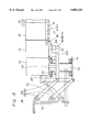
- the discharge unit 65 includes a sloping conveyor 91 and a forwarding conveyor 92, as shown in FIGS. 1 and 12.
- the forwarding conveyor 92 is a plastic chain conveyor similar to the retention conveyor 63.
- the sloping conveyor 91 is a chain conveyor which includes a number of cup holders 14 arranged in rows, with four cups in each row, on a transfer surface thereof, and is driven by a servo motor 43.
- the sloping conveyor 91 is connected to the transfer conveyor 64 and receives cups 20 with weighed articles put therein selected for combination, in respective ones of four cup holders 14.
- Cups 20 containing articles 21 selected for the combinations are successively conveyed to the discharge station 88 shown in FIG. 1, and the combinations of articles 21 in cups 20 are successively fed into the packaging apparatus 89.
- the packaging apparatus 89 reads the number of articles in each combination from memory means and packs articles in each combination in one pack. That is, the packaging apparatus 89 is arranged to package the number of articles, one, two, three, four, five, . . . , selected for each combination in one pack.
- weight values stored in memories M n+1 , M n+2 , . . . , and M n+ (i-n) are transferred to memories M n , M n+1 , . . . , and M n+ (i-n)-1, respectively (S112). Further, weight values stored in memories M m+1 , M m+2 , . . . , and M m+ (i-m) are transferred to memories M m , M m+1 , . . .
- the number s is subtracted from the number i of the originally stored weight values to know the number i of the currently stored weight values (S118).
- weight values resulting from successively weighing articles can be memorized, and the ordinal numbers of weight values stored in respective memories can be modified in accordance with the change of the ordinal numbers of non-selected articles left on the retention conveyor 63.
- weight values of articles standing on the retention conveyor 63 are stored, being associated with the respective articles.
- the combination weighing machine of the above-described embodiment is arranged such that articles are held in the same cups 20 from the time when they are put into the cups for weighing at the supplying stage 61, through the time when they are selected by combination computation, to the time when they are put into the packaging apparatus 89. Accordingly, adhesive or sticky articles never stick to the inner walls of individual chutes 9 and the collecting chute 10 as they do in conventional combination weighing machine, which results in improvement of precision and speed of weighing cut vegetables, pickles, roe etc. which are adhesive or sticky.
- the number of articles which can participate the combination computation can be increased by increasing the lengths of the retention conveyor 63 and the transfer conveyor 64 and increasing the number of the pushers 84.
- a conventional combination weighing machine like the one shown in FIG. 14, it is necessary to add a set of a straight feeder 3, a weighing hopper 5 and a memory hopper 8 in order to increase the number of weight values by one, but the present invention does not require such addition and, therefore, is economical.
- the present invention can provide improved precision and speed for the combination weighing of sticky articles over conventional combination weighing machines. Because a number of cups 20 containing weighed articles can stand on the retention conveyor 63, articles can be sent out successively from the weighers 62 after they are weighed and, therefore, the weighing of articles can be continuously and successively carried out. This improves an operating efficiency of the weighers 62 (i.e. the ratio of the time necessary for weighing articles in the supplying and weighing stage to the operating time of the combination weighing machine) over conventional machines.
- a second embodiment is described with reference to respective drawings.
- the difference of a combination weighing machine according to the second embodiment from the combination weighing machine according to the first embodiment is a supplying and weighing stage 114.
- the configurations and operations of the remaining portions namely, a waiting (e.g., the waiting station, also referred to as the waiting position) and transfer stage 115, a returning and discharge stage 116, a return stage 117 and apparatuses and parts disposed in these stages, are similar to those of the first embodiment.
- the same reference numerals as used for the first embodiment are used for such similar portions, and detailed descriptions thereof are not given.
- FIG. 18 is a plan view of a weigher apparatus forming a supplying and weighing stage 114
- FIG. 19 is a front elevational view thereof.
- the weigher apparatus receives empty cups (article holding means) 20 by means of a transport conveyor (receiving means) 66, and cups received by the transport conveyor 66 are fed by means of an empty cup pusher (pushing means) 70 onto a first elevator (first elevation means) 48 in its elevated position.
- the empty cups 20 thus fed are weighed by first weighers 49 (49-1, 49-2, 49-3, 49-4).
- Weight values W H1 , W H2 , W H3 , and W H4 (weight values of cups 20) obtained by the weighing in the first weighers 49 are subtracted in a subtracter (not shown), respectively from weight values W G1 , W G2 , W G3 , and W G4 (weight values of sums of weights of cups 20 and articles 21) obtained by the weighing in the four second weighers 62, whereby the weights W B1 , W B2 , W B3 , and W B4 of the respective articles 21 in the cups 20 are calculated. Since empty cups 20 are weighed beforehand by means of the first weighers 49, the weights of articles 21 currently put into cups 20 can be precisely measured even if such cups have various weights or part of articles remains sticking to such cups. Then, weighed articles in cups 20 are removed from the cups 20 and packaged.
- the transport conveyor 66, the empty cup pusher 70 and the first elevator 48 form feeding means recited in claim 6.
- the transport conveyor 66 is receiving means, which is, as shown in FIGS. 18 and 19, is a straight conveyor having its terminal end 69 disposed beside four first weighers 49.
- the transport conveyor 66 receives empty cups 20 from which weighed articles or articles to be weighed 21 (hereinafter, sometimes referred to simply as articles) have been discharged, and transport such cups 20 to the terminal end 69.
- a stop 41 is disposed in the terminal end 69, which can catch and hold cups 20.
- the transport conveyor 66 includes two looped plastic chains (top chains) 42, 42. The two opposite ends of each of the loops 42, 42 wrap around sprockets (not shown).
- the sprockets are linked with sprockets 44 disposed on a rotating shaft of a motor 43. As the motor 43 rotates, the two plastic chains 42, 42 are driven in a predetermined direction. Although not shown, the surfaces of the plastic chains 42, 42 contacting cups 20 are provided by plastic plates having small friction resistance. When cups 20 are transported to the terminal end 69 of the transport conveyor 66, the foremost cup 20 is caught by the stop 41, so that cups 20 stop moving on the terminal end 69.
- the guide plate 46 is provided by bending the foremost end of a retainer 47 which retains the plastic chain 42, and has an upper surface which is located above the transport surface (top surface) of the plastic chain 42 by H 9 (about 3 mm).
- the guide plate 46 is disposed beside the four first weighers 49, as shown in FIG. 18.
- the empty cup pusher 70 forms pushing means.
- the empty cup pusher 70 has the pad 71 at the tip end of its piston rod, as shown in FIGS. 18 and 19.
- four cups 20 standing on the terminal end 69 of the transport conveyor 66 are pushed to move over the guide plate 46 onto the first elevator 48 in its elevated position.
- the first elevator 48 is disposed in a first elevator apparatus 57.
- the first elevator apparatus 57 as shown in FIGS. 18 and 19, includes the first elevator 48 and two drive cylinders 51.
- the first elevator 48 includes five elevator plates 52 which are disposed horizontal, being spaced by a predetermined distance.
- the five elevator plates 52 are connected together by means of a connecting plate 53.
- the first elevator 48 is connected to the tip ends of the piston rods of the two drive cylinders 51 through a connecting frame 54, as shown in FIG. 19.
- a table 55 of one of the four first weighers 49 is located, as shown in FIG. 20(a).
- the two drive cylinders 51 parallel each other and are mounted on a weighing machine frame body 76.
- the drive cylinders 51 extend slantwise with the tip ends of their piston rods aimed from beneath the terminal end 69 of the transport conveyor 66 toward the tables 55 of the first weighers 49.
- the first elevator apparatus 57 moves the first elevator 4 between the elevated position shown in FIG. 19 and the lowered position shown in FIG. 17 by driving the drive cylinders 51 to stretch and retract. With the first elevator 48 driven to assume the elevated position shown in FIG.
- a second elevator apparatus 58 including the second elevator 50 is disposed in the stage succeeding the supplying stage 61.
- the second elevator apparatus 58 includes second elevator 50, a third elevator 59, two drive cylinders 60 for driving the second and third elevators 50 and 59, and an elevator link assembly A30 for transmitting driving force of the drive cylinders 60 to the second and third elevators 50 and 59.
- FIG. 21(a) is an enlarged plan view of the second and third elevators 50 and 59
- FIG. 21(b) is their enlarged front elevation view
- FIG. 21(c) is their enlarged side view.
- the third elevator 59 includes an elongated planar member of which the upper surface is disposed horizontal, as shown in FIG. 21. The opposite ends of the planar member are bent downward.
- the third elevator 59 is connected to the horizontal frame member A34 by means of connecting rods A36.
- the third elevator 59 and the second elevator 50 are mounted to the horizontal frame member A34 in such a manner that their upper surfaces are in the same level.
- a stop A37 having an L-shaped cross-section is disposed at the top end of each vertical link A35 to which the horizontal frame member A34 is connected.
- the elevator link assembly A30 includes, as shown in FIG. 14, a right-side link structure including two parallel links A38 and one of the vertical links A35; and a left-side link structure disposed symmetrical with the right-side link structure.
- the right-side and left-side link structures are the same, and only the right-side link structure is explained. No explanation of the left-side link structure is given.
- the right-side drive cylinder 60 may be an air cylinder, as shown in FIG. 14, and has a piston rod having its tip end rotatably connected to the upper end of the vertical link A35 via a connecting shaft A16.
- the base of the cylinder is rotatably connected to the frame body 76 of the weighing machine via a connecting shaft A17.
- the upper surface of the second elevator 50 is located about 1 mm below the upper edge of the fixed platform 67 of the supplying stage 61 (i.e. the surface on which cups 20 are conveyed), so that it can receive cups 20 which are pushed from the supplying stage 61.
- the upper surface of the second elevator 50 is H 3 ( ⁇ 3 mm) above the top surface of the tables A33 of the second weighers 62, so that it can support cups 20 in such a manner that weights of cups 20 do not act on the tables A33.
- the upper surface of the third elevator 59 is at the same level as the upper surface of the second elevator 50, so that it can receive cups 20 pushed out from the second elevator 50.
- the upper surface of the third elevator 59 is H 4 ( ⁇ 6 mm) above the transfer surface of the retention conveyor 63 and, therefore, can support cups 20 in such a manner that the bottoms of cups 20 do not contact the transfer surface.
- the upper surface of the second elevator 50 is below the upper surface of the tables A33 of the second weighers 62 by H 5 ( ⁇ 4 mm), so that cups 20 on it can be transferred onto the tables A33 of the second weighers 62.
- the upper surface of the third elevator 59 is below the transfer surface of the retention conveyor 63 by H 6 ( ⁇ 1 mm), so that cups 20 on it can be transferred onto the transfer surface of the retention conveyor 63.
- FIG. 15 is a front elevational view of the second elevator 50 of which the upper surface is at the same level as the upper surfaces of the tables A33.
- the transfer surface of the retention conveyor 63 is disposed at a level below the upper surfaces of the tables A33 of the second weighers 62 by H 8 ( ⁇ 3 mm) and the third elevator 59 is lowered in the direction (as indicated by the arrow A15 in FIG. 16) away from the supplying stage 61, as shown in FIG. 16, cups 20 on the third elevator 59 can be moved in the direction away from cups 20 on the second elevator 50 in the succeeding stage to transfer them onto the transfer surface of the retention conveyor 63.
- each table A33 does not receive any weight of cups 20 in front of, back of, on the right and on the left of the cup 20 on that table A33, or the weight of the cup 20 on each table A33 does not act on cups 20 in front of, back of, on the right and on the left of that cup 20. Therefore the weights, W G1 -1, W G2 -1, W G3 -1, and W G4 -1, of four cups 20 containing articles 21 therein on the respective tables A33 can be measured precisely by the second weighers 62.
- the retention conveyor 63 is a straight conveyor having its proximal end portion disposed beside the four second weighers 62, as shown in FIGS. 18 and 19, and receives and conveys in the direction indicated by arrows in FIG. 18, four cups 20 from the second weighers 62.
- the retention conveyor 63 is similar to that of the first embodiment, and the same reference numerals are attached to similar parts, giving no detailed description about them.
- the empty cup pusher 70 successively feeds four empty cups 20 on the terminal end 69 of the transport conveyor 66 onto the first elevator 48 in the elevated position. Cups are forwarded (in the direction 97) intermittently, contacting preceding and succeeding cups 20. These cups 20 are moved onto the retention conveyor 63 via the first elevator 48, the supplying stage 61 and the second elevator 50 which is elevated and lowered in synchronism with the first elevator 48.
- the first elevator 48 moves to its lowered position. While the first elevator 48 is being lowered, four empty cups 20 on it move toward the transport conveyor 66 (i.e. in the backward direction) so that they can be transferred onto the tables 55 of the respective first weighers 49-1 through 49-4, being kept separated from four cups 20 in front of them in the supplying stage 61 and four cups 20 back of them in the transport conveyor 66. When four cups 20 are placed on the four tables 55, the four first weighers 49 weigh four empty cups 20.
- the weights of the four empty cups 20, W H1 through W H4 can be measured precisely.
- the first elevator 48 rises to the elevated position so that weighed cups on the four tables 55 can be transferred onto the first elevator 48.
- the empty cup pusher 70 feeds next cups 20 on the transport conveyor 66 onto the first elevator 48, and the weighed cups 20 on the first elevator 48 are forwarded onto the supplying stage 61. In this way, successively weighed cups 20 are pushed forward on the supplying stage 61, and articles 21 are supplied at the supplying stage 61.
- Cups 20 with articles 21 supplied thereinto are successively forwarded onto the succeeding second elevator 50 which is in the elevated position, being in contact with preceding and succeeding cups 20 (see FIG. 14).
- the second elevator 50 moves toward its lowered position.
- four cups 20 on the second elevator 50 are moved toward the retention conveyor 63 (i.e. in the forward direction) so that they can be transferred onto the tables A33 of the second weighers 62, being kept separated from the succeeding four cups (see FIG. 16).
- the third elevator 59 is lowered in synchronism with the second elevator 50.
- the weights, W G1 -1, W G2 -1, W G3 -1, and W G4 -1, of four cups 20 with articles 21 contained therein can be measured precisely by the second weighers 62.
- the weights, W G1 -1, W G2 -1, W G3 -1, and W G4 -1, are stored in the memory section of the weighing machine.
- the weight W G1 -1 is the sum of the weight W H1 -1 of a cup 20 measured by the first weigher 49-1 and the weight W B1 -1 of an article 21 put in this cup 20.
- a subtracter of the computation control section (not shown) of the combination weighing machine computes successively (W G1 -1-W H1 -1), (W G2 -1-W H2 -1), (W G3 -1-W H3 -1) and (W G4 -1-W H4 -1), so that the weights of articles 21 in respective four cups 20, W B1 -1, W B2 -1, W B3 -1 and WB 4 -1 can be computed.
- the weights of articles 21 put in respective cups 20, (W B1 -1, W B2 -1, W B3 -1, W B4 -1), (W B1 -2, W B2 -2, W B3 -2, W B4 -2), . . . can be successively computed on the supplying stage 61 shown in FIG. 18.
- the weights of cups 20, (W H1 -1, W H2 -1, W H3 -1, W H4 -1), . . . are measured beforehand by the first weighers 49-1 through 49-4, and the weights of articles 21 (W H1 -1, W H2 -1, W H3 -1, W H4 -1), . . . , are computed by subtracting the weights of cups 20, (W H1 -1, W H2 -1, W H3 -1, W H4 -1), . . . , from the sum of the weights of the cups 20 and the articles 21 (W G1 -1, W G2 -1, W G3 -1, W G4 -1), . . . .
- the combination weighing machine according to the third embodiment comprises the combination weighing machine according to the second embodiment and a zero adjuster for adjusting the zero points of the four first weighers 49-1, 49-2, 49-3 and 49-4 and and the zero points of the four second weighers 62-1, 62-2, 62-3 and 62-4, and it is otherwise similar to the combination weighing machine of the second embodiment. Accordingly, detailed descriptions of similar portions are not given.
- the zero adjuster includes first zero adjuster means, second zero adjuster means, and stopping means.
- the first zero adjuster means provides zero-adjustment for the four first weighers 49-1, 49-2, 49-3 and 49-4 by changing the respective zero points at preset times, when the first elevator 48 is in the elevated position. In the elevated position of the first elevator 48, no weight of cups 20 acts on the tables 55 of the four first weighers 49-1 through 49-4, so that the weighers can be kept unloaded and the first weighers 49-1 through 49-4 can be provided with zero-adjustment.
- the second zero adjuster means provides zero-adjustment for the four second weighers 62-1, 62-2, 62-3 and 62-4 by changing the respective zero points at preset times, when the second elevator 50 is in the elevated position.
- no weight of cups 20 acts on the tables A33 of the four second weighers 62-1 through 62-4, so that the weighers can be kept unloaded and the first weighers 62-1 through 62-4 can be provided with zero-adjustment.
- the stopping means keeps the empty cup pusher 70 in the retracted position for a predetermined time period at the time when the zero-adjustment is made, but it may be kept in its stretched position for the predetermined time period.
- first weighers 49 and four second weighers 62 a different number A than four for the first and second weighers may be used.
- the number of the rows of cups 20 on the first and second elevators 48 and 50 and the supplying stage 61 is made equal to the number A selected for the first and second weighers 49 and 62, and cups 20 with weighed articles 20 contained therein are forwarded to the succeeding retention conveyor 63 when the number of cups 20 on the retention conveyor 63 becomes (12-A) or less.
- cups 20 With this combination weighing machine, while cups 20 are being transported, cups 20 are filled with articles to be weighed, the weights of articles are measured, and those ones of weighed articles 21 which have been selected for combination are discharged from cups 20, whereby combinations of articles, the combined weights of which are within the predetermined weight range, are obtained. Emptied cups 20 are repetitively used to hold and weigh articles 21 therein. All cups 20 are formed to have the same weight.
- the filling conveyor G14 is a belt conveyor which conveys cups 20 successively to a predetermined filling position shown in FIG. 24, where each cup 20 stops moving and is filled with an article 21 having a weight which approximates a predetermined weight.
- a cup 20 filled with an article is conveyed to the succeeding weighing conveyor G15. Accordingly, although not shown, cups 20 are fed to the filling conveyor G14 at predetermined intervals.
- the filling of cups may be done by a filling machine or may be done manually.
- the filling conveyor G14 forwards a cup with an article contained therein to the weighing conveyor after a preceding article has been weighed by the weighing conveyor 15.
- the weighing conveyor G15 is a belt conveyor with a weight detector, e.g. a load cell, which measures the sum of the weights of a cup 20 and an article within the cup 20 while the cup 20 is being conveyed. Because the weight of the cup 20 is known, a computation control section (not shown) subtracts the weight of the cup 20 from the sum weight to compute the weight of the article. The cup 20 with the weighed article is forwarded to the succeeding retention conveyor G16 when the number of cups 20 standing on the retention conveyor G16 becomes less than fourteen.
- a weight detector e.g. a load cell
- the retention conveyor G16 is a belt conveyor having a relatively smooth conveyor surface, and, as shown in FIG. 24, receives cups 20 with weighed articles contained therein which are successively forwarded from the weighing conveyor G15.
- the retention conveyor G16 is so arranged that fourteen cups 20 can stand on it in a line, with a predetermined spacing disposed between adjacent ones.
- Fourteen cups are caught at predetermined stop positions by respective ones of first through fourteenth, fourteen stops G22 (G22-1 through G22-14), as shown in FIGS. 24 and 28.
- Weight values of respective articles are stored in the memory section (not shown), being associated with the respective stop positions.
- the memory section is connected to the computation control section.
- each of the stops G22 has a concave surface which contacts each cup 20 so that that cup 20 may not be displaced.
- the first, rightmost stop G22-1 shown in FIG. 24 is secured to the frame (not shown) of the retention conveyor G16, whereas the remaining, second through fourteenth stops G22-2 through G22-14 are mounted respectively on the lower ends of piston rods G24 of thirteen air cylinders G23-2 through G23-14 disposed above the retention conveyor G16 as shown in FIG. 28. They are driven by the respective air cylinders to move between the lower positions (i.e. cup catching positions) and the upper positions (i.e. cup non-catching positions).
- the leftward two stops G22-3 and G22-4 are in their upper positions (cup non-catching positions), and the stop G22-2 which is the second from the right is in the lower position (cup catching position).
- the rightmost stop G22-1 is fixed to the frame and, therefore, is always able to catch and hold a cup 20 in that position.
- first through fourteenth cup detectors G25-1 through G25-14 are disposed with a predetermined spacing between adjacent ones, along the left side viewed in the conveying direction of the retention conveyor G16.
- the cup detectors G25-1 through G25-14 detect cups 20 caught and held by the respective stops G22-1 through G22-14 in the respective positions shown in FIG. 24, and develop detection signals when they detect cups 20.
- Behind the respective cup detectors G25-1 through G25-14 are first through fourteenth pushers G26-1 through G26-14, which have respective air cylinders.
- Pads G27-1 through G27-14 are at the respective front ends of the piston rods, and have concave surfaces which contact cups 20 so that cups 20 may not be disengaged from the pads G27-1 through G27-14 when they push cups 20 out of the retention conveyor G16.
- the pads G27-1 through G27-14 are driven by the respective air cylinders to move between pushing positions (i.e. the stretched position of the pushers) for pushing respective cups onto the transfer conveyor G17 and stand-by positions (i.e. the retracted positions of the pushers).
- the pushing positions of the pads (the stretched positions of the pushers) and the stand-by positions (the retracted positions of the pushers) are shown in FIG. 25.
- the first cup detector G25-1 associated with the first stop G22-1 detects a cup 20 and the detection signal is applied to the computation control section.
- the computation control section drives the air cylinder G23-2 to stretch so that the second stop G22-3 moves from its upper position to the lower position (cup catching position), as shown in FIG. 28.
- a second cup 20 forwarded comes into contact with the second stop G22-2 and stops there.
- the second cup detector G25-2 associated with the second stop G22-2 detects the second cup 20, and the computation control section drives the air cylinder G23-3 to stretch so that the third stop G22-3 shown in FIG. 28 moves to its lower position (cup catching position).
- the combination computing means includes the computation control section (not shown) provided by a central processing unit (CPU), and predetermined programs stored in the memory section (not shown) connected to the computation control section, and performs predetermined combination computations. Specifically, the combination computing means prepares various combinations weights of articles 21 measured by the weighing conveyor G15, and selects articles having weights the sum of which is within a predetermined weight range and is equal to or closest to a preset target weight.
- CPU central processing unit
- Combination computation performed by the combination computing means is started when combination computation start memory number preset by an operator through a preset indication section (not shown) reaches K.
- the combination computation start memory number is the condition for the combination computing means to start computation. This condition is, for example, that the number of cups 20 standing on the retention conveyor G16 (i.e. the number of weight values of weighed articles stored in the memory section) K becomes ten or more.
- weight values stored in the memory section being less than ten, there is a small possibility that combinations of weights the sum of which is within the predetermined weight range are found by the combination computation, and, therefore, computation is not performed.
- the combination computing means selected the second, eleventh and thirteenth articles (weight values) as shown in FIG. 25 as providing a desired combination.
- the second, eleventh and thirteenth pushers G26-2, G26-11 and G26-13 stretch and drive the cups 20 containing the second, eleventh and thirteenth articles out of the retention conveyor G16 onto the transfer conveyor G17 (which is a belt conveyor) disposed adjacent to the retention conveyor G16.
- the second, eleventh and thirteenth pushers G26-2, G26-11 and G26-13 retract to their retracted positions as shown in FIG. 26, and the second, eleventh and thirteenth cups 20 transferred onto the transfer conveyor G17 are conveyed on the transfer conveyor G17 to the discharge unit G18.
- the fourteen cups containing weighed articles namely, the three cups 20 forwarded from the weighing conveyor G15 and the eleven cups 20 on the retention conveyor G16, are then caught by the respective stops G22-1 through G22-14 and held in position shown in FIG. 24, in the manner described above.
- the weight values of the articles in the respective stop positions are stored in the memory section, being associated with the respective stop positions.
- the discharge unit G18 includes the feed-in conveyor G28, the sloping conveyor G29 and a feed-out conveyor G31.
- the feed-in conveyor G28 and the feed-out conveyor G31 are belt conveyors.
- the sloping conveyor G29 is a chain conveyor with a number of cup holders G32 on the transfer surface thereof as shown in FIG. 30.
- the feed-in conveyor G28 is linked with the transfer conveyor G17 and receives and feeds cups containing articles selected for combination from the transfer conveyor G17 into a push-out device G33 shown in FIG. 29.
- the push-out device G33 drives an air cylinder G34 with a predetermined timing to cause cups 20 to be fed one by one to the input end of the sloping conveyor G29.
- One cup 20 is put into one cup holder G32.
- Each cup 20 in the cup holders G32 is turned upside down at the top end of the sloping conveyor G29, as shown in FIG. 30, and gets out of the cup holders G32.
- the cup 20 falls into a positioning cylindrical member G35 and stops in a discharge position G36. Because a cup 20 in the discharge position G36 is upside down and because shock is applied to the cup due to falling, an article 21 in the cup 20 goes out of the cup 20 and is put into the packaging machine G30 through a port G38 in a cup receiver plate G37.
- a fifth embodiment is described with reference to FIGS. 31 through 34.
- a combination weighing machine according to the fifth embodiment is the combination weighing machine according to the fourth embodiment with an exception that a roller conveyor G42 shown in FIG. 31 is used as the retention conveyor G16 of the fourth embodiment, and the stops G22-1 through G22-14 are disposed beneath the roller conveyor G42. Otherwise, the combination weighing machine of the fifth embodiment is similar to that of the fourth embodiment, and, therefore, similar portions are not described any more. It should be noted, however, that although not shown in FIG. 31, cup detectors G25-1 through G25-14 similar to the ones of the fourth embodiment are also used. According to the fifth embodiment, since the stops G22-2 through G22-14 are disposed below the retention conveyor G16, articles put in cups 20 can be visually inspected easily.
- the combination weighing machine of this embodiment can stop fourteen cups 20 at predetermined positions on the roller conveyor G42. After selected cups 20 are pushed out from the roller conveyor G42, different cups 20 containing weighed articles are successively fed in, as in the fourth embodiment, and the remaining cups 20 on the roller conveyor G42 are conveyed forward so that a maximum of fourteen cups 20 can be made to stand.
- the belt conveyor G49 of the sixth embodiment includes fourteen separate conveyors G50-1 through G50-14, each having such a size as to be capable of holding one cup 20.
- Each of the separate conveyors includes three cup holding rollers G51, a drive roller G52, and a belt G53 wrapped around the four rollers.
- Each of the fourteen drive rollers G52 of the fourteen separate belt conveyors G50-1 through G50-14 is connected to a drive shaft G58 connected to the rotation shaft of the motor G57 via one of electromagnetic clutches G54 with a brake and bevel gears G55 and G56.
- other cups 20 are held at predetermined positions on the second through fourteenth separate belt conveyors G50-2 through G50-14. Thereafter, articles put in some of the cups 20 are selected for combination, and the cups 20 containing the selected articles are pushed on the transfer conveyor G17. In a manner similar to the fourth embodiment, another cups 20 containing weighed articles are successively fed onto the separate conveyors, and the cups remaining on the separate conveyors are fed forward, so that a maximum of fourteen cups 20 can be made to stand on the separate belt conveyors.
- a combination weighing machine includes four of the filling conveyor G14 shown in FIG. 24, which are linked in series, and after them, four of the weighing conveyor 15 in parallel (or in series) so as to receive and weigh cups 20 with weighed articles put therein.
- the retention conveyor G16 is disposed after the weighing conveyors G15 so that cups 20 with articles having their weights measured by the weighing conveyors G15 can stand on the retention conveyor G16.
- the number of cups 20 which can be kept on the retention conveyor G16 is a maximum of ten, for example.
- the number of the articles (weight values) to be selected for combination is equal to the number of the weighing conveyors G15, i.e. four (a predetermined number). Otherwise, the combination weighing machine of the seventh embodiment is similar to the one of the fourth embodiment, and similar portions are not described any more.
- a combination of articles put in the predetermined number, four, of cups 20 are selected by the combination computing means and forwarded from the retention conveyor G16, and each time four cups 20 are forwarded from the retention conveyor G16, the predetermined number, four, of cups 20 containing articles 21 weighed by the four weighing conveyors G15 are successively supplied to the retention conveyor G16.
- the four weighing conveyors G15 can operate continuously with their full ability.
- combination computation is performed when a maximum of ten cups 20 which can wait on the retention conveyor G16 (i.e. cups 20 containing weighed articles) are forwarded and held on the retention conveyor G16, always ten articles can be used for selecting combinations, which can provide stabilized weighing precision.
- the seventh embodiment has been described as including four weighing conveyors disposed in parallel (or in series) and as selecting the same number, four (predetermined number) of articles for combination as the weighing conveyors, a plurality (predetermined number), different from four, of weighing conveyors G15 may be linked in parallel (or in series), with the number of articles (weight values) to be selected for combination being equal to the plurality (predetermined number) of the weighing conveyors G15.
- the seventh embodiment has been described as having ten cups 20; made to stand on the retention conveyor G16, it may be arranged such that a different number, e.g. from eight to twenty, of cups 20 may stand on the retention conveyor G16.
- a standby conveyor may be disposed between the weighing conveyor G15 and the retention conveyor G16 to permit a plurality of cups 20 containing weighed articles to stand by thereon.
- cups 20 with weighed articles put therein on the standby conveyor can be forward to the retention conveyor G16 as soon as cups 20 with weighed articles contained therein are pushed out from the retention conveyor G16, so that a waiting time can be eliminated, which otherwise would be necessary for waiting for the number of cups 20 containing weighed articles selectable for combination to become equal to the combination computation start memory number K.
- first through seventh embodiments have been described as including the retention conveyor 63 and the transfer conveyor 64 each comprising two plastic chain loops, but they each may comprise single plastic chain loops. What is important is that each of the retention conveyor 63 and the transfer conveyor 64 should be able to convey cups 20 in a predetermined direction and hold cups 20 following a foremost cup 20 in such a manner that succeeding cups 20 push preceding ones, on the conveyor surface when the foremost cup 20 is caught and stopped.
- the number of the weighers 62 has been described to be four, but a different number of weighers may be used.
- the supplying stage 61 must be configured such as to arrange forward cups 20 in the same number of rows as the number of the weighers 62.
- the number of the weighers 62 is preferably approximately equal to the number of weight values to be selected for forming combinations. This is because by supplying, to the retention conveyor 63, cups 20 approximately equal in number to cups selected for combination and fed out of the retention conveyor 63, a substantially constant number of cups 20 can be made to stand on the retention conveyor 63 and the weighers 62 can be operated at a relatively high operating efficiency, without being idle.
- the number of the weighers 62 may be approximately equal to the average of the numbers of weight values (i.e. the average of cups 20) selected for one combination divided by a natural number.
- the first through third embodiments have been described as having two standby cups 20, namely, the eleventh and twelfth cups from the foremost cup on the retention conveyor 63, but two or other number of cups 20 may be used as standby cups on the retention conveyor 63.
- Standby cups may be kept on a separate standby transfer unit, e.g. a conveyor. In other words, cups 20 forwarded from the weighers 62 are received on such separate standby transfer unit, and then successively conveyed at predetermined times onto the retention conveyor 63.
Landscapes
- Physics & Mathematics (AREA)
- General Physics & Mathematics (AREA)
- Sorting Of Articles (AREA)
- Branching, Merging, And Special Transfer Between Conveyors (AREA)
Applications Claiming Priority (5)
| Application Number | Priority Date | Filing Date | Title |
|---|---|---|---|
| JP29192295A JP3577378B2 (ja) | 1995-06-22 | 1995-10-12 | 組合せ計量方法及び組合せ秤 |
| JP7-291922 | 1995-10-12 | ||
| JP8-056815 | 1996-02-19 | ||
| JP05681596A JP3625947B2 (ja) | 1996-02-19 | 1996-02-19 | 計量装置 |
| PCT/JP1996/002955 WO1997014020A1 (fr) | 1995-10-12 | 1996-10-11 | Procede de pesage combinatoire et balance combinatoire |
Publications (1)
| Publication Number | Publication Date |
|---|---|
| US5889235A true US5889235A (en) | 1999-03-30 |
Family
ID=26397808
Family Applications (1)
| Application Number | Title | Priority Date | Filing Date |
|---|---|---|---|
| US08/860,546 Expired - Lifetime US5889235A (en) | 1995-10-12 | 1996-10-11 | Combination weighing method and combination balance |
Country Status (6)
| Country | Link |
|---|---|
| US (1) | US5889235A (de) |
| EP (1) | EP0806638B1 (de) |
| KR (1) | KR100214429B1 (de) |
| CN (1) | CN1110691C (de) |
| DE (1) | DE69635547T2 (de) |
| WO (1) | WO1997014020A1 (de) |
Cited By (15)
| Publication number | Priority date | Publication date | Assignee | Title |
|---|---|---|---|---|
| US6262377B1 (en) * | 1993-07-06 | 2001-07-17 | Scanvagt A/S | Method and a system for building up weighed-out portions of object |
| US6380495B1 (en) * | 1999-11-24 | 2002-04-30 | The Procter & Gamble Company | Method for controlling an amount of material delivered during a material transfer |
| US6437256B1 (en) * | 1999-08-06 | 2002-08-20 | Ishida Co., Ltd. | Combination weighing apparatus |
| US20050173159A1 (en) * | 2003-06-05 | 2005-08-11 | Ishida Co., Ltd. | Combination calculation method and combination measuring device |
| US20060060511A1 (en) * | 2004-08-10 | 2006-03-23 | Yt Ingenieria Ltda. | Automatic weighting system for variable weight items |
| US20060266560A1 (en) * | 2005-05-26 | 2006-11-30 | Masayoshi Nakajima | Conveying device, and combination weighing device and quality inspection device provided therewith |
| US20060289206A1 (en) * | 2003-10-10 | 2006-12-28 | Ishida Co., Ltd. | Metering apparatus, combination metering apparatus with the metering apparatus, and metering method |
| EP1760012A1 (de) * | 2005-09-02 | 2007-03-07 | Dematic GmbH & Co. KG | Verfahren und Vorrichtung zur Bereitstellung einer vorbestimmbaren Sequenz von Transportbehältern |
| US20070119633A1 (en) * | 2003-11-10 | 2007-05-31 | Ishida Co., Ltd. | Measuring device |
| US20090277132A1 (en) * | 2005-09-26 | 2009-11-12 | Masayoshi Nakajima | Combination weighing device, and bag-manufacturing and packaging system and combination weighing system provided with the same |
| CN100592042C (zh) * | 2003-10-10 | 2010-02-24 | 株式会社石田 | 计量装置及备有该装置的组合计量装置、计量方法 |
| US20110094621A1 (en) * | 2007-03-16 | 2011-04-28 | Shozo Kawanishi | Link apparatus, weighing apparatus using a link apparatus, packaging apparatus using a link apparatus and weighing and packaging system using a link apparatus |
| EP2620756A4 (de) * | 2010-09-22 | 2014-02-26 | Yamato Scale Co Ltd | Wiegesystem und wiege-arbeitsverfahren |
| US20160290852A1 (en) * | 2015-04-03 | 2016-10-06 | Bot Llc | Method and apparatus for sorting and combining fragile and varying density pieces |
| US20200353510A1 (en) * | 2019-05-09 | 2020-11-12 | Steven Theodore Chandler | Automated method and system for sorting and combining varying density payloads |
Families Citing this family (13)
| Publication number | Priority date | Publication date | Assignee | Title |
|---|---|---|---|---|
| JP4034097B2 (ja) * | 2002-03-20 | 2008-01-16 | 株式会社イシダ | 循環式組合せ計量装置 |
| JP4233267B2 (ja) * | 2002-04-16 | 2009-03-04 | 大和製衡株式会社 | 粉粒体計量装置及び粉粒体計量方法 |
| JP4046289B2 (ja) * | 2004-11-18 | 2008-02-13 | 勝三 川西 | 組合せ秤 |
| CN101061378B (zh) * | 2004-11-25 | 2010-09-29 | 川西胜三 | 组合秤 |
| JP2006153462A (ja) * | 2004-11-25 | 2006-06-15 | Yamato Scale Co Ltd | 組合せ秤 |
| JP4101797B2 (ja) * | 2004-11-26 | 2008-06-18 | 勝三 川西 | 組合せ秤 |
| RU2399889C1 (ru) * | 2006-07-21 | 2010-09-20 | Созо КАВАНИСИ | Комбинационный весовой дозатор |
| JP5102100B2 (ja) * | 2008-05-09 | 2012-12-19 | 株式会社イシダ | 組合せ計量装置 |
| CN102390578B (zh) * | 2011-07-29 | 2014-05-28 | 上海朝洋机电设备有限公司 | 定量数粒的实现方法 |
| CN103332331B (zh) * | 2013-06-21 | 2015-09-02 | 杭州中亚机械股份有限公司 | 一种翻杯机构以及具有该翻杯机构的灌装机 |
| JP7013127B2 (ja) * | 2017-01-27 | 2022-01-31 | 大和製衡株式会社 | 物品供給装置 |
| EP3617669B1 (de) * | 2017-04-28 | 2023-01-25 | Shozo Kawanishi | Wiegevorrichtung |
| EP4141392B1 (de) * | 2020-04-22 | 2026-02-11 | Yamato Scale Co., Ltd. | Kombinationswaage |
Citations (6)
| Publication number | Priority date | Publication date | Assignee | Title |
|---|---|---|---|---|
| JPS5847718A (ja) * | 1981-09-10 | 1983-03-19 | Ishida Scales Mfg Co Ltd | 等ピツチ間隔開け装置 |
| US4418772A (en) * | 1981-04-14 | 1983-12-06 | Kabushiki Kaisha Ishida Koki Seisakusho | Combinatorial weighing method and apparatus therefor |
| US4420051A (en) * | 1980-02-01 | 1983-12-13 | Kabushiki Kaisha Ishida Koki Seisakusho | Weighing apparatus |
| JPH06217564A (ja) * | 1994-01-17 | 1994-08-05 | Seiko Epson Corp | 超音波モータ |
| US5340949A (en) * | 1990-09-17 | 1994-08-23 | Anritsu Corporation | Metering system capable of easily effecting high-accuracy metering for various works including sticky materials |
| JPH0829242A (ja) * | 1994-07-18 | 1996-02-02 | Contec:Kk | 計量方法と計量装置 |
Family Cites Families (1)
| Publication number | Priority date | Publication date | Assignee | Title |
|---|---|---|---|---|
| JPS62175624A (ja) * | 1986-01-29 | 1987-08-01 | Nanbu Denki Seisakusho:Kk | 鶏卵組み合わせ計量方法及び包装装置 |
-
1996
- 1996-10-11 KR KR1019970703920A patent/KR100214429B1/ko not_active Expired - Lifetime
- 1996-10-11 EP EP96933624A patent/EP0806638B1/de not_active Expired - Lifetime
- 1996-10-11 CN CN96191209A patent/CN1110691C/zh not_active Expired - Lifetime
- 1996-10-11 WO PCT/JP1996/002955 patent/WO1997014020A1/ja not_active Ceased
- 1996-10-11 DE DE69635547T patent/DE69635547T2/de not_active Expired - Lifetime
- 1996-10-11 US US08/860,546 patent/US5889235A/en not_active Expired - Lifetime
Patent Citations (6)
| Publication number | Priority date | Publication date | Assignee | Title |
|---|---|---|---|---|
| US4420051A (en) * | 1980-02-01 | 1983-12-13 | Kabushiki Kaisha Ishida Koki Seisakusho | Weighing apparatus |
| US4418772A (en) * | 1981-04-14 | 1983-12-06 | Kabushiki Kaisha Ishida Koki Seisakusho | Combinatorial weighing method and apparatus therefor |
| JPS5847718A (ja) * | 1981-09-10 | 1983-03-19 | Ishida Scales Mfg Co Ltd | 等ピツチ間隔開け装置 |
| US5340949A (en) * | 1990-09-17 | 1994-08-23 | Anritsu Corporation | Metering system capable of easily effecting high-accuracy metering for various works including sticky materials |
| JPH06217564A (ja) * | 1994-01-17 | 1994-08-05 | Seiko Epson Corp | 超音波モータ |
| JPH0829242A (ja) * | 1994-07-18 | 1996-02-02 | Contec:Kk | 計量方法と計量装置 |
Cited By (25)
| Publication number | Priority date | Publication date | Assignee | Title |
|---|---|---|---|---|
| US6262377B1 (en) * | 1993-07-06 | 2001-07-17 | Scanvagt A/S | Method and a system for building up weighed-out portions of object |
| US6437256B1 (en) * | 1999-08-06 | 2002-08-20 | Ishida Co., Ltd. | Combination weighing apparatus |
| US6380495B1 (en) * | 1999-11-24 | 2002-04-30 | The Procter & Gamble Company | Method for controlling an amount of material delivered during a material transfer |
| US20050173159A1 (en) * | 2003-06-05 | 2005-08-11 | Ishida Co., Ltd. | Combination calculation method and combination measuring device |
| US7015399B2 (en) | 2003-06-05 | 2006-03-21 | Ishida Co., Ltd. | Combination calculation method and combination measuring device |
| EP1510796A4 (de) * | 2003-06-05 | 2011-01-12 | Ishida Seisakusho | Kombinatorisches betriebsverfahren und kombinationswaage |
| US7390981B2 (en) | 2003-10-10 | 2008-06-24 | Ishida Co., Ltd. | Weighing device for weighing target object in container, combination weighing device including the same, and weighing method |
| US20060289206A1 (en) * | 2003-10-10 | 2006-12-28 | Ishida Co., Ltd. | Metering apparatus, combination metering apparatus with the metering apparatus, and metering method |
| CN100592042C (zh) * | 2003-10-10 | 2010-02-24 | 株式会社石田 | 计量装置及备有该装置的组合计量装置、计量方法 |
| US20070119633A1 (en) * | 2003-11-10 | 2007-05-31 | Ishida Co., Ltd. | Measuring device |
| US7332679B2 (en) * | 2003-11-10 | 2008-02-19 | Ishida Co., Ltd. | Weighing device equipped with power supply mechanism having fixed section and movable section |
| US20060060511A1 (en) * | 2004-08-10 | 2006-03-23 | Yt Ingenieria Ltda. | Automatic weighting system for variable weight items |
| US20060266560A1 (en) * | 2005-05-26 | 2006-11-30 | Masayoshi Nakajima | Conveying device, and combination weighing device and quality inspection device provided therewith |
| US7332680B2 (en) * | 2005-05-26 | 2008-02-19 | Ishida Co., Ltd. | Conveying device having container order changing mechanism, and combination weighing device and quality inspection device provided therewith |
| EP1760012A1 (de) * | 2005-09-02 | 2007-03-07 | Dematic GmbH & Co. KG | Verfahren und Vorrichtung zur Bereitstellung einer vorbestimmbaren Sequenz von Transportbehältern |
| US20090277132A1 (en) * | 2005-09-26 | 2009-11-12 | Masayoshi Nakajima | Combination weighing device, and bag-manufacturing and packaging system and combination weighing system provided with the same |
| US7633019B2 (en) * | 2005-09-26 | 2009-12-15 | Ishida Co., Ltd. | Combination weighing device, bag-manufacturing and packaging system and combination weighing system provided with the same |
| US20110094621A1 (en) * | 2007-03-16 | 2011-04-28 | Shozo Kawanishi | Link apparatus, weighing apparatus using a link apparatus, packaging apparatus using a link apparatus and weighing and packaging system using a link apparatus |
| US8866029B2 (en) * | 2007-03-16 | 2014-10-21 | Shozo Kawanishi | Link apparatus, weighing apparatus using a link apparatus, packaging apparatus using a link apparatus and weighing and packaging system using a link apparatus |
| EP2620756A4 (de) * | 2010-09-22 | 2014-02-26 | Yamato Scale Co Ltd | Wiegesystem und wiege-arbeitsverfahren |
| US9228884B2 (en) | 2010-09-22 | 2016-01-05 | Yamato Scale Co., Ltd. | Hand-operated weighing system and weighing work method |
| US20160290852A1 (en) * | 2015-04-03 | 2016-10-06 | Bot Llc | Method and apparatus for sorting and combining fragile and varying density pieces |
| US10036664B2 (en) * | 2015-04-03 | 2018-07-31 | Bot Llc | Method and apparatus for sorting and combining fragile and varying density pieces |
| US20200353510A1 (en) * | 2019-05-09 | 2020-11-12 | Steven Theodore Chandler | Automated method and system for sorting and combining varying density payloads |
| US11534802B2 (en) * | 2019-05-09 | 2022-12-27 | Steven Theodore Chandler | Automated method and system for sorting and combining varying density payloads |
Also Published As
| Publication number | Publication date |
|---|---|
| DE69635547T2 (de) | 2006-06-29 |
| WO1997014020A1 (fr) | 1997-04-17 |
| KR100214429B1 (ko) | 1999-08-02 |
| CN1166200A (zh) | 1997-11-26 |
| EP0806638A4 (de) | 1999-12-22 |
| EP0806638B1 (de) | 2005-12-07 |
| DE69635547D1 (de) | 2006-01-12 |
| EP0806638A1 (de) | 1997-11-12 |
| CN1110691C (zh) | 2003-06-04 |
Similar Documents
| Publication | Publication Date | Title |
|---|---|---|
| US5889235A (en) | Combination weighing method and combination balance | |
| EP1176405B1 (de) | Kombinationswaage mit einer Versorgungseinheit | |
| US4661917A (en) | Mixing combinatorial counting and weighing method, and apparatus therefor | |
| US4442932A (en) | Combinatorial weighing apparatus | |
| US4522274A (en) | Combinatorial weighing method | |
| EP0105756B1 (de) | Kombinatorischer Wägeapparat und Methode | |
| JP2630368B2 (ja) | 計量装置 | |
| JP3587922B2 (ja) | 投入物品の反転排出装置及び排出シュート | |
| JP3577378B2 (ja) | 組合せ計量方法及び組合せ秤 | |
| US7361850B2 (en) | Method and apparatus for counting items in a container | |
| JP3625947B2 (ja) | 計量装置 | |
| JP3617863B2 (ja) | 組合せ秤 | |
| JP3647549B2 (ja) | 組合せ秤 | |
| JP3367037B2 (ja) | 組合せ計量装置 | |
| JP3810544B2 (ja) | 計量装置及びその計量装置を備える組合せ秤 | |
| KR200350685Y1 (ko) | 자동 계수 장치 | |
| JP3617870B2 (ja) | 組合せ秤 | |
| JP3617871B2 (ja) | 組合せ秤 | |
| JP3640732B2 (ja) | 組合せ秤の高速処理方法及び高速処理機能付き組合せ秤 | |
| JP3645018B2 (ja) | 組合せ秤 | |
| JP3725680B2 (ja) | 組合せ秤における物品保持手段の移送装置 | |
| JP3687820B2 (ja) | 組合せ計量方法及び組合せ秤 | |
| JP3725676B2 (ja) | 組合せ秤の物品供給装置 | |
| JPH03148402A (ja) | もやし類の定量供給装置 | |
| JP2022053175A (ja) | 組合せ計量装置 |
Legal Events
| Date | Code | Title | Description |
|---|---|---|---|
| AS | Assignment |
Owner name: YAMATO SCALE COMPANY LIMITED, JAPAN Free format text: ASSIGNMENT OF ASSIGNORS INTEREST;ASSIGNORS:KAWANISHI, SHOZO;HIGUCHI, HIROSHI;MIKATA, YOSHITAKA;AND OTHERS;REEL/FRAME:008676/0340 Effective date: 19970527 |
|
| STCF | Information on status: patent grant |
Free format text: PATENTED CASE |
|
| FEPP | Fee payment procedure |
Free format text: PAYOR NUMBER ASSIGNED (ORIGINAL EVENT CODE: ASPN); ENTITY STATUS OF PATENT OWNER: LARGE ENTITY |
|
| FPAY | Fee payment |
Year of fee payment: 4 |
|
| FPAY | Fee payment |
Year of fee payment: 8 |
|
| FPAY | Fee payment |
Year of fee payment: 12 |