JP5689470B2 - 埋め込みストレッサを有する高性能fetを形成するための方法および構造 - Google Patents
埋め込みストレッサを有する高性能fetを形成するための方法および構造 Download PDFInfo
- Publication number
- JP5689470B2 JP5689470B2 JP2012530914A JP2012530914A JP5689470B2 JP 5689470 B2 JP5689470 B2 JP 5689470B2 JP 2012530914 A JP2012530914 A JP 2012530914A JP 2012530914 A JP2012530914 A JP 2012530914A JP 5689470 B2 JP5689470 B2 JP 5689470B2
- Authority
- JP
- Japan
- Prior art keywords
- semiconductor material
- semiconductor
- epitaxy
- region
- epitaxial
- Prior art date
- Legal status (The legal status is an assumption and is not a legal conclusion. Google has not performed a legal analysis and makes no representation as to the accuracy of the status listed.)
- Expired - Fee Related
Links
- 238000000034 method Methods 0.000 title description 56
- 239000004065 semiconductor Substances 0.000 claims description 210
- 239000000463 material Substances 0.000 claims description 143
- 239000000758 substrate Substances 0.000 claims description 58
- 238000000407 epitaxy Methods 0.000 claims description 37
- 125000006850 spacer group Chemical group 0.000 claims description 37
- 239000002019 doping agent Substances 0.000 claims description 32
- 229910052751 metal Inorganic materials 0.000 claims description 23
- 239000002184 metal Substances 0.000 claims description 23
- 238000009792 diffusion process Methods 0.000 claims description 17
- 229910045601 alloy Inorganic materials 0.000 claims description 13
- 239000000956 alloy Substances 0.000 claims description 13
- 125000005843 halogen group Chemical group 0.000 claims description 13
- 229910000577 Silicon-germanium Inorganic materials 0.000 claims description 10
- 125000004429 atom Chemical group 0.000 claims description 9
- 238000005468 ion implantation Methods 0.000 claims description 7
- NJPPVKZQTLUDBO-UHFFFAOYSA-N novaluron Chemical compound C1=C(Cl)C(OC(F)(F)C(OC(F)(F)F)F)=CC=C1NC(=O)NC(=O)C1=C(F)C=CC=C1F NJPPVKZQTLUDBO-UHFFFAOYSA-N 0.000 claims description 7
- 239000007943 implant Substances 0.000 claims description 3
- 230000008569 process Effects 0.000 description 38
- 238000000137 annealing Methods 0.000 description 13
- 230000015572 biosynthetic process Effects 0.000 description 13
- 238000005530 etching Methods 0.000 description 12
- 238000002955 isolation Methods 0.000 description 9
- 229910052710 silicon Inorganic materials 0.000 description 8
- XUIMIQQOPSSXEZ-UHFFFAOYSA-N Silicon Chemical compound [Si] XUIMIQQOPSSXEZ-UHFFFAOYSA-N 0.000 description 7
- 238000010586 diagram Methods 0.000 description 7
- 229910021332 silicide Inorganic materials 0.000 description 7
- 239000010703 silicon Substances 0.000 description 7
- FVBUAEGBCNSCDD-UHFFFAOYSA-N silicide(4-) Chemical compound [Si-4] FVBUAEGBCNSCDD-UHFFFAOYSA-N 0.000 description 6
- 238000005229 chemical vapour deposition Methods 0.000 description 5
- 239000013078 crystal Substances 0.000 description 5
- 238000000151 deposition Methods 0.000 description 5
- 238000005137 deposition process Methods 0.000 description 5
- 239000003989 dielectric material Substances 0.000 description 5
- 238000007373 indentation Methods 0.000 description 5
- 150000004767 nitrides Chemical class 0.000 description 5
- 238000001039 wet etching Methods 0.000 description 5
- IJGRMHOSHXDMSA-UHFFFAOYSA-N Atomic nitrogen Chemical compound N#N IJGRMHOSHXDMSA-UHFFFAOYSA-N 0.000 description 4
- PXHVJJICTQNCMI-UHFFFAOYSA-N Nickel Chemical compound [Ni] PXHVJJICTQNCMI-UHFFFAOYSA-N 0.000 description 4
- 238000000231 atomic layer deposition Methods 0.000 description 4
- 238000001312 dry etching Methods 0.000 description 4
- 238000011049 filling Methods 0.000 description 4
- 238000011065 in-situ storage Methods 0.000 description 4
- 238000004519 manufacturing process Methods 0.000 description 4
- 238000005240 physical vapour deposition Methods 0.000 description 4
- 238000001020 plasma etching Methods 0.000 description 4
- 229910021420 polycrystalline silicon Inorganic materials 0.000 description 4
- 238000012545 processing Methods 0.000 description 4
- LEVVHYCKPQWKOP-UHFFFAOYSA-N [Si].[Ge] Chemical compound [Si].[Ge] LEVVHYCKPQWKOP-UHFFFAOYSA-N 0.000 description 3
- 230000004913 activation Effects 0.000 description 3
- 229910052782 aluminium Inorganic materials 0.000 description 3
- 230000008021 deposition Effects 0.000 description 3
- 230000000694 effects Effects 0.000 description 3
- 230000005669 field effect Effects 0.000 description 3
- 239000007789 gas Substances 0.000 description 3
- 238000002513 implantation Methods 0.000 description 3
- 239000012212 insulator Substances 0.000 description 3
- 230000003647 oxidation Effects 0.000 description 3
- 238000007254 oxidation reaction Methods 0.000 description 3
- 238000000623 plasma-assisted chemical vapour deposition Methods 0.000 description 3
- 239000002243 precursor Substances 0.000 description 3
- 229910052721 tungsten Inorganic materials 0.000 description 3
- 239000010937 tungsten Substances 0.000 description 3
- VHUUQVKOLVNVRT-UHFFFAOYSA-N Ammonium hydroxide Chemical compound [NH4+].[OH-] VHUUQVKOLVNVRT-UHFFFAOYSA-N 0.000 description 2
- XKRFYHLGVUSROY-UHFFFAOYSA-N Argon Chemical compound [Ar] XKRFYHLGVUSROY-UHFFFAOYSA-N 0.000 description 2
- KRHYYFGTRYWZRS-UHFFFAOYSA-N Fluorane Chemical compound F KRHYYFGTRYWZRS-UHFFFAOYSA-N 0.000 description 2
- KDLHZDBZIXYQEI-UHFFFAOYSA-N Palladium Chemical compound [Pd] KDLHZDBZIXYQEI-UHFFFAOYSA-N 0.000 description 2
- KJTLSVCANCCWHF-UHFFFAOYSA-N Ruthenium Chemical compound [Ru] KJTLSVCANCCWHF-UHFFFAOYSA-N 0.000 description 2
- 229910052581 Si3N4 Inorganic materials 0.000 description 2
- VYPSYNLAJGMNEJ-UHFFFAOYSA-N Silicium dioxide Chemical compound O=[Si]=O VYPSYNLAJGMNEJ-UHFFFAOYSA-N 0.000 description 2
- 229910002367 SrTiO Inorganic materials 0.000 description 2
- RTAQQCXQSZGOHL-UHFFFAOYSA-N Titanium Chemical compound [Ti] RTAQQCXQSZGOHL-UHFFFAOYSA-N 0.000 description 2
- NRTOMJZYCJJWKI-UHFFFAOYSA-N Titanium nitride Chemical compound [Ti]#N NRTOMJZYCJJWKI-UHFFFAOYSA-N 0.000 description 2
- HMDDXIMCDZRSNE-UHFFFAOYSA-N [C].[Si] Chemical compound [C].[Si] HMDDXIMCDZRSNE-UHFFFAOYSA-N 0.000 description 2
- XAGFODPZIPBFFR-UHFFFAOYSA-N aluminium Chemical compound [Al] XAGFODPZIPBFFR-UHFFFAOYSA-N 0.000 description 2
- 239000000908 ammonium hydroxide Substances 0.000 description 2
- 230000004888 barrier function Effects 0.000 description 2
- 230000000903 blocking effect Effects 0.000 description 2
- 239000007772 electrode material Substances 0.000 description 2
- 238000005516 engineering process Methods 0.000 description 2
- 238000001459 lithography Methods 0.000 description 2
- 229910044991 metal oxide Inorganic materials 0.000 description 2
- 150000004706 metal oxides Chemical class 0.000 description 2
- 150000002739 metals Chemical class 0.000 description 2
- 239000000203 mixture Substances 0.000 description 2
- 229910052759 nickel Inorganic materials 0.000 description 2
- 229910052757 nitrogen Inorganic materials 0.000 description 2
- 230000000737 periodic effect Effects 0.000 description 2
- BASFCYQUMIYNBI-UHFFFAOYSA-N platinum Chemical compound [Pt] BASFCYQUMIYNBI-UHFFFAOYSA-N 0.000 description 2
- 238000004549 pulsed laser deposition Methods 0.000 description 2
- 229910052707 ruthenium Inorganic materials 0.000 description 2
- HQVNEWCFYHHQES-UHFFFAOYSA-N silicon nitride Chemical compound N12[Si]34N5[Si]62N3[Si]51N64 HQVNEWCFYHHQES-UHFFFAOYSA-N 0.000 description 2
- 229910052814 silicon oxide Inorganic materials 0.000 description 2
- 229910052715 tantalum Inorganic materials 0.000 description 2
- GUVRBAGPIYLISA-UHFFFAOYSA-N tantalum atom Chemical compound [Ta] GUVRBAGPIYLISA-UHFFFAOYSA-N 0.000 description 2
- 229910052719 titanium Inorganic materials 0.000 description 2
- 239000010936 titanium Substances 0.000 description 2
- WFKWXMTUELFFGS-UHFFFAOYSA-N tungsten Chemical compound [W] WFKWXMTUELFFGS-UHFFFAOYSA-N 0.000 description 2
- -1 tungsten nitride Chemical class 0.000 description 2
- 229910018072 Al 2 O 3 Inorganic materials 0.000 description 1
- ZOXJGFHDIHLPTG-UHFFFAOYSA-N Boron Chemical compound [B] ZOXJGFHDIHLPTG-UHFFFAOYSA-N 0.000 description 1
- 229910002601 GaN Inorganic materials 0.000 description 1
- 229910001218 Gallium arsenide Inorganic materials 0.000 description 1
- UFHFLCQGNIYNRP-UHFFFAOYSA-N Hydrogen Chemical compound [H][H] UFHFLCQGNIYNRP-UHFFFAOYSA-N 0.000 description 1
- 229910000673 Indium arsenide Inorganic materials 0.000 description 1
- 229910021193 La 2 O 3 Inorganic materials 0.000 description 1
- OAICVXFJPJFONN-UHFFFAOYSA-N Phosphorus Chemical compound [P] OAICVXFJPJFONN-UHFFFAOYSA-N 0.000 description 1
- 229910010413 TiO 2 Inorganic materials 0.000 description 1
- AXQKVSDUCKWEKE-UHFFFAOYSA-N [C].[Ge].[Si] Chemical compound [C].[Ge].[Si] AXQKVSDUCKWEKE-UHFFFAOYSA-N 0.000 description 1
- 229910052787 antimony Inorganic materials 0.000 description 1
- WATWJIUSRGPENY-UHFFFAOYSA-N antimony atom Chemical compound [Sb] WATWJIUSRGPENY-UHFFFAOYSA-N 0.000 description 1
- 238000013459 approach Methods 0.000 description 1
- 229910052786 argon Inorganic materials 0.000 description 1
- 229910052785 arsenic Inorganic materials 0.000 description 1
- RQNWIZPPADIBDY-UHFFFAOYSA-N arsenic atom Chemical compound [As] RQNWIZPPADIBDY-UHFFFAOYSA-N 0.000 description 1
- 229910052796 boron Inorganic materials 0.000 description 1
- 238000006243 chemical reaction Methods 0.000 description 1
- 238000000224 chemical solution deposition Methods 0.000 description 1
- 229910017052 cobalt Inorganic materials 0.000 description 1
- 239000010941 cobalt Substances 0.000 description 1
- GUTLYIVDDKVIGB-UHFFFAOYSA-N cobalt atom Chemical compound [Co] GUTLYIVDDKVIGB-UHFFFAOYSA-N 0.000 description 1
- 230000000295 complement effect Effects 0.000 description 1
- 150000001875 compounds Chemical class 0.000 description 1
- 239000004020 conductor Substances 0.000 description 1
- 238000007796 conventional method Methods 0.000 description 1
- PMHQVHHXPFUNSP-UHFFFAOYSA-M copper(1+);methylsulfanylmethane;bromide Chemical compound Br[Cu].CSC PMHQVHHXPFUNSP-UHFFFAOYSA-M 0.000 description 1
- 230000000593 degrading effect Effects 0.000 description 1
- 238000000280 densification Methods 0.000 description 1
- 238000013461 design Methods 0.000 description 1
- 229910052732 germanium Inorganic materials 0.000 description 1
- 229910052734 helium Inorganic materials 0.000 description 1
- 239000001307 helium Substances 0.000 description 1
- SWQJXJOGLNCZEY-UHFFFAOYSA-N helium atom Chemical compound [He] SWQJXJOGLNCZEY-UHFFFAOYSA-N 0.000 description 1
- 239000001257 hydrogen Substances 0.000 description 1
- 229910052739 hydrogen Inorganic materials 0.000 description 1
- 239000012535 impurity Substances 0.000 description 1
- 229910052738 indium Inorganic materials 0.000 description 1
- RPQDHPTXJYYUPQ-UHFFFAOYSA-N indium arsenide Chemical compound [In]#[As] RPQDHPTXJYYUPQ-UHFFFAOYSA-N 0.000 description 1
- APFVFJFRJDLVQX-UHFFFAOYSA-N indium atom Chemical compound [In] APFVFJFRJDLVQX-UHFFFAOYSA-N 0.000 description 1
- 239000011810 insulating material Substances 0.000 description 1
- 238000010884 ion-beam technique Methods 0.000 description 1
- 229910052746 lanthanum Inorganic materials 0.000 description 1
- 238000000608 laser ablation Methods 0.000 description 1
- 239000007788 liquid Substances 0.000 description 1
- 239000003595 mist Substances 0.000 description 1
- 229910003465 moissanite Inorganic materials 0.000 description 1
- 229910021421 monocrystalline silicon Inorganic materials 0.000 description 1
- RUFLMLWJRZAWLJ-UHFFFAOYSA-N nickel silicide Chemical compound [Ni]=[Si]=[Ni] RUFLMLWJRZAWLJ-UHFFFAOYSA-N 0.000 description 1
- 229910021334 nickel silicide Inorganic materials 0.000 description 1
- 229910052763 palladium Inorganic materials 0.000 description 1
- 238000000059 patterning Methods 0.000 description 1
- 229910052698 phosphorus Inorganic materials 0.000 description 1
- 239000011574 phosphorus Substances 0.000 description 1
- 229910052697 platinum Inorganic materials 0.000 description 1
- 229920005591 polysilicon Polymers 0.000 description 1
- 238000004151 rapid thermal annealing Methods 0.000 description 1
- 150000004760 silicates Chemical class 0.000 description 1
- 229910010271 silicon carbide Inorganic materials 0.000 description 1
- 238000004544 sputter deposition Methods 0.000 description 1
- 238000003860 storage Methods 0.000 description 1
- 239000000126 substance Substances 0.000 description 1
- MZLGASXMSKOWSE-UHFFFAOYSA-N tantalum nitride Chemical compound [Ta]#N MZLGASXMSKOWSE-UHFFFAOYSA-N 0.000 description 1
- 229910021341 titanium silicide Inorganic materials 0.000 description 1
- WQJQOUPTWCFRMM-UHFFFAOYSA-N tungsten disilicide Chemical compound [Si]#[W]#[Si] WQJQOUPTWCFRMM-UHFFFAOYSA-N 0.000 description 1
- 229910021342 tungsten silicide Inorganic materials 0.000 description 1
- 238000007740 vapor deposition Methods 0.000 description 1
Images


Classifications
-
- H—ELECTRICITY
- H01—ELECTRIC ELEMENTS
- H01L—SEMICONDUCTOR DEVICES NOT COVERED BY CLASS H10
- H01L29/00—Semiconductor devices adapted for rectifying, amplifying, oscillating or switching, or capacitors or resistors with at least one potential-jump barrier or surface barrier, e.g. PN junction depletion layer or carrier concentration layer; Details of semiconductor bodies or of electrodes thereof ; Multistep manufacturing processes therefor
- H01L29/02—Semiconductor bodies ; Multistep manufacturing processes therefor
- H01L29/12—Semiconductor bodies ; Multistep manufacturing processes therefor characterised by the materials of which they are formed
- H01L29/16—Semiconductor bodies ; Multistep manufacturing processes therefor characterised by the materials of which they are formed including, apart from doping materials or other impurities, only elements of Group IV of the Periodic System
- H01L29/161—Semiconductor bodies ; Multistep manufacturing processes therefor characterised by the materials of which they are formed including, apart from doping materials or other impurities, only elements of Group IV of the Periodic System including two or more of the elements provided for in group H01L29/16, e.g. alloys
- H01L29/165—Semiconductor bodies ; Multistep manufacturing processes therefor characterised by the materials of which they are formed including, apart from doping materials or other impurities, only elements of Group IV of the Periodic System including two or more of the elements provided for in group H01L29/16, e.g. alloys in different semiconductor regions, e.g. heterojunctions
-
- H—ELECTRICITY
- H01—ELECTRIC ELEMENTS
- H01L—SEMICONDUCTOR DEVICES NOT COVERED BY CLASS H10
- H01L29/00—Semiconductor devices adapted for rectifying, amplifying, oscillating or switching, or capacitors or resistors with at least one potential-jump barrier or surface barrier, e.g. PN junction depletion layer or carrier concentration layer; Details of semiconductor bodies or of electrodes thereof ; Multistep manufacturing processes therefor
- H01L29/40—Electrodes ; Multistep manufacturing processes therefor
- H01L29/41—Electrodes ; Multistep manufacturing processes therefor characterised by their shape, relative sizes or dispositions
- H01L29/417—Electrodes ; Multistep manufacturing processes therefor characterised by their shape, relative sizes or dispositions carrying the current to be rectified, amplified or switched
- H01L29/41725—Source or drain electrodes for field effect devices
- H01L29/41775—Source or drain electrodes for field effect devices characterised by the proximity or the relative position of the source or drain electrode and the gate electrode, e.g. the source or drain electrode separated from the gate electrode by side-walls or spreading around or above the gate electrode
-
- H—ELECTRICITY
- H01—ELECTRIC ELEMENTS
- H01L—SEMICONDUCTOR DEVICES NOT COVERED BY CLASS H10
- H01L29/00—Semiconductor devices adapted for rectifying, amplifying, oscillating or switching, or capacitors or resistors with at least one potential-jump barrier or surface barrier, e.g. PN junction depletion layer or carrier concentration layer; Details of semiconductor bodies or of electrodes thereof ; Multistep manufacturing processes therefor
- H01L29/66—Types of semiconductor device ; Multistep manufacturing processes therefor
- H01L29/66007—Multistep manufacturing processes
- H01L29/66075—Multistep manufacturing processes of devices having semiconductor bodies comprising group 14 or group 13/15 materials
- H01L29/66227—Multistep manufacturing processes of devices having semiconductor bodies comprising group 14 or group 13/15 materials the devices being controllable only by the electric current supplied or the electric potential applied, to an electrode which does not carry the current to be rectified, amplified or switched, e.g. three-terminal devices
- H01L29/66409—Unipolar field-effect transistors
- H01L29/66477—Unipolar field-effect transistors with an insulated gate, i.e. MISFET
- H01L29/66568—Lateral single gate silicon transistors
- H01L29/66575—Lateral single gate silicon transistors where the source and drain or source and drain extensions are self-aligned to the sides of the gate
- H01L29/6659—Lateral single gate silicon transistors where the source and drain or source and drain extensions are self-aligned to the sides of the gate with both lightly doped source and drain extensions and source and drain self-aligned to the sides of the gate, e.g. lightly doped drain [LDD] MOSFET, double diffused drain [DDD] MOSFET
-
- H—ELECTRICITY
- H01—ELECTRIC ELEMENTS
- H01L—SEMICONDUCTOR DEVICES NOT COVERED BY CLASS H10
- H01L29/00—Semiconductor devices adapted for rectifying, amplifying, oscillating or switching, or capacitors or resistors with at least one potential-jump barrier or surface barrier, e.g. PN junction depletion layer or carrier concentration layer; Details of semiconductor bodies or of electrodes thereof ; Multistep manufacturing processes therefor
- H01L29/66—Types of semiconductor device ; Multistep manufacturing processes therefor
- H01L29/66007—Multistep manufacturing processes
- H01L29/66075—Multistep manufacturing processes of devices having semiconductor bodies comprising group 14 or group 13/15 materials
- H01L29/66227—Multistep manufacturing processes of devices having semiconductor bodies comprising group 14 or group 13/15 materials the devices being controllable only by the electric current supplied or the electric potential applied, to an electrode which does not carry the current to be rectified, amplified or switched, e.g. three-terminal devices
- H01L29/66409—Unipolar field-effect transistors
- H01L29/66477—Unipolar field-effect transistors with an insulated gate, i.e. MISFET
- H01L29/66568—Lateral single gate silicon transistors
- H01L29/66613—Lateral single gate silicon transistors with a gate recessing step, e.g. using local oxidation
- H01L29/66628—Lateral single gate silicon transistors with a gate recessing step, e.g. using local oxidation recessing the gate by forming single crystalline semiconductor material at the source or drain location
-
- H—ELECTRICITY
- H01—ELECTRIC ELEMENTS
- H01L—SEMICONDUCTOR DEVICES NOT COVERED BY CLASS H10
- H01L29/00—Semiconductor devices adapted for rectifying, amplifying, oscillating or switching, or capacitors or resistors with at least one potential-jump barrier or surface barrier, e.g. PN junction depletion layer or carrier concentration layer; Details of semiconductor bodies or of electrodes thereof ; Multistep manufacturing processes therefor
- H01L29/66—Types of semiconductor device ; Multistep manufacturing processes therefor
- H01L29/66007—Multistep manufacturing processes
- H01L29/66075—Multistep manufacturing processes of devices having semiconductor bodies comprising group 14 or group 13/15 materials
- H01L29/66227—Multistep manufacturing processes of devices having semiconductor bodies comprising group 14 or group 13/15 materials the devices being controllable only by the electric current supplied or the electric potential applied, to an electrode which does not carry the current to be rectified, amplified or switched, e.g. three-terminal devices
- H01L29/66409—Unipolar field-effect transistors
- H01L29/66477—Unipolar field-effect transistors with an insulated gate, i.e. MISFET
- H01L29/66568—Lateral single gate silicon transistors
- H01L29/66636—Lateral single gate silicon transistors with source or drain recessed by etching or first recessed by etching and then refilled
-
- H—ELECTRICITY
- H01—ELECTRIC ELEMENTS
- H01L—SEMICONDUCTOR DEVICES NOT COVERED BY CLASS H10
- H01L29/00—Semiconductor devices adapted for rectifying, amplifying, oscillating or switching, or capacitors or resistors with at least one potential-jump barrier or surface barrier, e.g. PN junction depletion layer or carrier concentration layer; Details of semiconductor bodies or of electrodes thereof ; Multistep manufacturing processes therefor
- H01L29/66—Types of semiconductor device ; Multistep manufacturing processes therefor
- H01L29/68—Types of semiconductor device ; Multistep manufacturing processes therefor controllable by only the electric current supplied, or only the electric potential applied, to an electrode which does not carry the current to be rectified, amplified or switched
- H01L29/76—Unipolar devices, e.g. field effect transistors
- H01L29/772—Field effect transistors
- H01L29/78—Field effect transistors with field effect produced by an insulated gate
- H01L29/7833—Field effect transistors with field effect produced by an insulated gate with lightly doped drain or source extension, e.g. LDD MOSFET's; DDD MOSFET's
- H01L29/7834—Field effect transistors with field effect produced by an insulated gate with lightly doped drain or source extension, e.g. LDD MOSFET's; DDD MOSFET's with a non-planar structure, e.g. the gate or the source or the drain being non-planar
-
- H—ELECTRICITY
- H01—ELECTRIC ELEMENTS
- H01L—SEMICONDUCTOR DEVICES NOT COVERED BY CLASS H10
- H01L29/00—Semiconductor devices adapted for rectifying, amplifying, oscillating or switching, or capacitors or resistors with at least one potential-jump barrier or surface barrier, e.g. PN junction depletion layer or carrier concentration layer; Details of semiconductor bodies or of electrodes thereof ; Multistep manufacturing processes therefor
- H01L29/66—Types of semiconductor device ; Multistep manufacturing processes therefor
- H01L29/68—Types of semiconductor device ; Multistep manufacturing processes therefor controllable by only the electric current supplied, or only the electric potential applied, to an electrode which does not carry the current to be rectified, amplified or switched
- H01L29/76—Unipolar devices, e.g. field effect transistors
- H01L29/772—Field effect transistors
- H01L29/78—Field effect transistors with field effect produced by an insulated gate
- H01L29/7842—Field effect transistors with field effect produced by an insulated gate means for exerting mechanical stress on the crystal lattice of the channel region, e.g. using a flexible substrate
- H01L29/7848—Field effect transistors with field effect produced by an insulated gate means for exerting mechanical stress on the crystal lattice of the channel region, e.g. using a flexible substrate the means being located in the source/drain region, e.g. SiGe source and drain
-
- H—ELECTRICITY
- H01—ELECTRIC ELEMENTS
- H01L—SEMICONDUCTOR DEVICES NOT COVERED BY CLASS H10
- H01L21/00—Processes or apparatus adapted for the manufacture or treatment of semiconductor or solid state devices or of parts thereof
- H01L21/02—Manufacture or treatment of semiconductor devices or of parts thereof
- H01L21/04—Manufacture or treatment of semiconductor devices or of parts thereof the devices having at least one potential-jump barrier or surface barrier, e.g. PN junction, depletion layer or carrier concentration layer
- H01L21/18—Manufacture or treatment of semiconductor devices or of parts thereof the devices having at least one potential-jump barrier or surface barrier, e.g. PN junction, depletion layer or carrier concentration layer the devices having semiconductor bodies comprising elements of Group IV of the Periodic System or AIIIBV compounds with or without impurities, e.g. doping materials
- H01L21/22—Diffusion of impurity materials, e.g. doping materials, electrode materials, into or out of a semiconductor body, or between semiconductor regions; Interactions between two or more impurities; Redistribution of impurities
- H01L21/225—Diffusion of impurity materials, e.g. doping materials, electrode materials, into or out of a semiconductor body, or between semiconductor regions; Interactions between two or more impurities; Redistribution of impurities using diffusion into or out of a solid from or into a solid phase, e.g. a doped oxide layer
- H01L21/2251—Diffusion into or out of group IV semiconductors
- H01L21/2254—Diffusion into or out of group IV semiconductors from or through or into an applied layer, e.g. photoresist, nitrides
- H01L21/2257—Diffusion into or out of group IV semiconductors from or through or into an applied layer, e.g. photoresist, nitrides the applied layer being silicon or silicide or SIPOS, e.g. polysilicon, porous silicon
-
- H—ELECTRICITY
- H01—ELECTRIC ELEMENTS
- H01L—SEMICONDUCTOR DEVICES NOT COVERED BY CLASS H10
- H01L21/00—Processes or apparatus adapted for the manufacture or treatment of semiconductor or solid state devices or of parts thereof
- H01L21/02—Manufacture or treatment of semiconductor devices or of parts thereof
- H01L21/04—Manufacture or treatment of semiconductor devices or of parts thereof the devices having at least one potential-jump barrier or surface barrier, e.g. PN junction, depletion layer or carrier concentration layer
- H01L21/18—Manufacture or treatment of semiconductor devices or of parts thereof the devices having at least one potential-jump barrier or surface barrier, e.g. PN junction, depletion layer or carrier concentration layer the devices having semiconductor bodies comprising elements of Group IV of the Periodic System or AIIIBV compounds with or without impurities, e.g. doping materials
- H01L21/26—Bombardment with radiation
- H01L21/263—Bombardment with radiation with high-energy radiation
- H01L21/265—Bombardment with radiation with high-energy radiation producing ion implantation
- H01L21/26586—Bombardment with radiation with high-energy radiation producing ion implantation characterised by the angle between the ion beam and the crystal planes or the main crystal surface
-
- H—ELECTRICITY
- H01—ELECTRIC ELEMENTS
- H01L—SEMICONDUCTOR DEVICES NOT COVERED BY CLASS H10
- H01L29/00—Semiconductor devices adapted for rectifying, amplifying, oscillating or switching, or capacitors or resistors with at least one potential-jump barrier or surface barrier, e.g. PN junction depletion layer or carrier concentration layer; Details of semiconductor bodies or of electrodes thereof ; Multistep manufacturing processes therefor
- H01L29/66—Types of semiconductor device ; Multistep manufacturing processes therefor
- H01L29/66007—Multistep manufacturing processes
- H01L29/66075—Multistep manufacturing processes of devices having semiconductor bodies comprising group 14 or group 13/15 materials
- H01L29/66227—Multistep manufacturing processes of devices having semiconductor bodies comprising group 14 or group 13/15 materials the devices being controllable only by the electric current supplied or the electric potential applied, to an electrode which does not carry the current to be rectified, amplified or switched, e.g. three-terminal devices
- H01L29/66409—Unipolar field-effect transistors
- H01L29/66477—Unipolar field-effect transistors with an insulated gate, i.e. MISFET
- H01L29/665—Unipolar field-effect transistors with an insulated gate, i.e. MISFET using self aligned silicidation, i.e. salicide
-
- H—ELECTRICITY
- H01—ELECTRIC ELEMENTS
- H01L—SEMICONDUCTOR DEVICES NOT COVERED BY CLASS H10
- H01L29/00—Semiconductor devices adapted for rectifying, amplifying, oscillating or switching, or capacitors or resistors with at least one potential-jump barrier or surface barrier, e.g. PN junction depletion layer or carrier concentration layer; Details of semiconductor bodies or of electrodes thereof ; Multistep manufacturing processes therefor
- H01L29/66—Types of semiconductor device ; Multistep manufacturing processes therefor
- H01L29/66007—Multistep manufacturing processes
- H01L29/66075—Multistep manufacturing processes of devices having semiconductor bodies comprising group 14 or group 13/15 materials
- H01L29/66227—Multistep manufacturing processes of devices having semiconductor bodies comprising group 14 or group 13/15 materials the devices being controllable only by the electric current supplied or the electric potential applied, to an electrode which does not carry the current to be rectified, amplified or switched, e.g. three-terminal devices
- H01L29/66409—Unipolar field-effect transistors
- H01L29/66477—Unipolar field-effect transistors with an insulated gate, i.e. MISFET
- H01L29/66545—Unipolar field-effect transistors with an insulated gate, i.e. MISFET using a dummy, i.e. replacement gate in a process wherein at least a part of the final gate is self aligned to the dummy gate
-
- H—ELECTRICITY
- H01—ELECTRIC ELEMENTS
- H01L—SEMICONDUCTOR DEVICES NOT COVERED BY CLASS H10
- H01L29/00—Semiconductor devices adapted for rectifying, amplifying, oscillating or switching, or capacitors or resistors with at least one potential-jump barrier or surface barrier, e.g. PN junction depletion layer or carrier concentration layer; Details of semiconductor bodies or of electrodes thereof ; Multistep manufacturing processes therefor
- H01L29/66—Types of semiconductor device ; Multistep manufacturing processes therefor
- H01L29/66007—Multistep manufacturing processes
- H01L29/66075—Multistep manufacturing processes of devices having semiconductor bodies comprising group 14 or group 13/15 materials
- H01L29/66227—Multistep manufacturing processes of devices having semiconductor bodies comprising group 14 or group 13/15 materials the devices being controllable only by the electric current supplied or the electric potential applied, to an electrode which does not carry the current to be rectified, amplified or switched, e.g. three-terminal devices
- H01L29/66409—Unipolar field-effect transistors
- H01L29/66477—Unipolar field-effect transistors with an insulated gate, i.e. MISFET
- H01L29/6656—Unipolar field-effect transistors with an insulated gate, i.e. MISFET using multiple spacer layers, e.g. multiple sidewall spacers
Landscapes
- Engineering & Computer Science (AREA)
- Microelectronics & Electronic Packaging (AREA)
- Power Engineering (AREA)
- Condensed Matter Physics & Semiconductors (AREA)
- General Physics & Mathematics (AREA)
- Physics & Mathematics (AREA)
- Ceramic Engineering (AREA)
- Computer Hardware Design (AREA)
- Manufacturing & Machinery (AREA)
- Chemical & Material Sciences (AREA)
- Crystallography & Structural Chemistry (AREA)
- Insulated Gate Type Field-Effect Transistor (AREA)
- Recrystallisation Techniques (AREA)
- Thin Film Transistor (AREA)
Description
Claims (14)
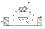
- 半導体基板の上面上に位置する少なくとも1つのゲート・スタックと、
前記少なくとも1つのゲート・スタックの対向側に存在する1対のくぼみ領域の内部で前記少なくとも1つのゲート・スタックの設置場所に位置するドーピングされた第1のエピタキシ半導体材料であって、前記少なくとも1つのゲート・スタックのチャネル上にひずみを誘発する、第1のエピタキシ半導体材料と、
前記くぼみ領域の各々において前記第1のエピタキシ半導体材料の上面内に位置する拡散拡張領域であって、前記少なくとも1つのゲート・スタックの下の前記半導体基板内まで延びる拡散拡張領域と、
前記拡散拡張領域の上面上に位置する第2のエピタキシ半導体材料であって、前記第1のエピタキシ半導体材料よりも高いドーパント濃度を有する、第2のエピタキシ半導体材料と、を含み、
前記拡散拡張領域は、前記第2のエピタキシ半導体材料から導出されたドーパントを含む領域として画定される、半導体構造。 - 前記1対のくぼみ領域が、前記半導体基板の台座によって相互に分離されている、請求項1に記載の半導体構造。
- 前記台座が直線状の側壁を有する、請求項2に記載の半導体構造。
- 前記台座が砂時計の形状を有する、請求項2に記載の半導体構造。
- 前記第1のエピタキシ半導体材料が、5x10¹⁸原子/cm3未満のドーパント濃度を有する、請求項1または4に記載の半導体構造。
- 前記第2のエピタキシ半導体材料が1x10¹⁹原子/cm3より大きいドーパント濃度を有する、請求項1または5に記載の半導体構造。
- 前記第1のエピタキシ半導体材料がSiGeを含む、請求項1または6に記載の半導体構造。
- 前記第1のエピタキシ半導体材料がSi:Cを含む、請求項1または6に記載の半導体構造。
- 前記半導体基板内に位置するハロー注入領域を更に含み、前記ハロー領域が前記拡散拡張領域および前記第1のエピタキシ半導体材料に接触している、請求項1または8に記載の半導体構造。
- 前記第2のエピタキシ半導体材料の少なくとも上面上に位置する金属半導体合金を更に含む、請求項1または9に記載の半導体構造。
- 前記半導体基板の表面上に位置する基部を有し、
前記少なくとも1つのゲート・スタックの側壁と接触する側方縁部を有する第1のスペーサと、前記第2のエピタキシ半導体材料の上面上に位置する基部を有し、前記第1のスペーサの側壁と接触する側方縁部を有する第2のスペーサと、を更に含む、請求項1または10に記載の半導体構造。 - 深部のイオン注入ソース領域も深部のイオン注入ドレイン領域も存在しない、請求項1に記載の半導体構造。
- 前記第1のエピタキシ半導体材料の上面が、前記半導体基板の前記上面と同一平面であるか、または前記上面よりも上に延出する、請求項1に記載の半導体構造。
- 前記第1のエピタキシ半導体材料の上面が前記半導体基板の前記上面の下に位置する、請求項1に記載の半導体構造。
Applications Claiming Priority (3)
| Application Number | Priority Date | Filing Date | Title |
|---|---|---|---|
| US12/566,004 US8022488B2 (en) | 2009-09-24 | 2009-09-24 | High-performance FETs with embedded stressors |
| US12/566,004 | 2009-09-24 | ||
| PCT/US2010/048039 WO2011037743A2 (en) | 2009-09-24 | 2010-09-08 | Method and structure for forming high-performance fets with embedded stressors |
Publications (3)
| Publication Number | Publication Date |
|---|---|
| JP2013506291A JP2013506291A (ja) | 2013-02-21 |
| JP2013506291A5 JP2013506291A5 (ja) | 2014-08-14 |
| JP5689470B2 true JP5689470B2 (ja) | 2015-03-25 |
Family
ID=43755874
Family Applications (1)
| Application Number | Title | Priority Date | Filing Date |
|---|---|---|---|
| JP2012530914A Expired - Fee Related JP5689470B2 (ja) | 2009-09-24 | 2010-09-08 | 埋め込みストレッサを有する高性能fetを形成するための方法および構造 |
Country Status (7)
| Country | Link |
|---|---|
| US (1) | US8022488B2 (ja) |
| JP (1) | JP5689470B2 (ja) |
| CN (1) | CN102511081B (ja) |
| DE (1) | DE112010002895B4 (ja) |
| GB (1) | GB2486839B (ja) |
| TW (1) | TW201125124A (ja) |
| WO (1) | WO2011037743A2 (ja) |
Families Citing this family (47)
| Publication number | Priority date | Publication date | Assignee | Title |
|---|---|---|---|---|
| JP2011086728A (ja) * | 2009-10-14 | 2011-04-28 | Renesas Electronics Corp | 半導体装置およびその製造方法 |
| US8236660B2 (en) | 2010-04-21 | 2012-08-07 | International Business Machines Corporation | Monolayer dopant embedded stressor for advanced CMOS |
| US8299535B2 (en) * | 2010-06-25 | 2012-10-30 | International Business Machines Corporation | Delta monolayer dopants epitaxy for embedded source/drain silicide |
| KR101721036B1 (ko) | 2010-09-02 | 2017-03-29 | 삼성전자주식회사 | 반도체 소자 및 그 제조 방법 |
| US9698054B2 (en) | 2010-10-19 | 2017-07-04 | Taiwan Semiconductor Manufacturing Company, Ltd. | Strained structure of a p-type field effect transistor |
| US8946064B2 (en) * | 2011-06-16 | 2015-02-03 | International Business Machines Corporation | Transistor with buried silicon germanium for improved proximity control and optimized recess shape |
| DE102011080438B3 (de) * | 2011-08-04 | 2013-01-31 | Globalfoundries Inc. | Herstellverfahren für einen N-Kanaltransistor mit einer Metallgateelektrodenstruktur mit großem ε und einem reduzierten Reihenwiderstand durch epitaktisch hergestelltes Halbleitermaterial in den Drain- und Sourcebereichen und N-Kanaltransistor |
| US9064892B2 (en) | 2011-08-30 | 2015-06-23 | Taiwan Semiconductor Manufacturing Company, Ltd. | Semiconductor devices utilizing partially doped stressor film portions and methods for forming the same |
| CN102280379B (zh) * | 2011-09-05 | 2016-06-01 | 上海集成电路研发中心有限公司 | 一种应变硅nmos器件的制造方法 |
| CN103137480B (zh) * | 2011-11-25 | 2015-07-08 | 中芯国际集成电路制造(上海)有限公司 | Mos器件的形成方法及其形成的mos器件 |
| US8658505B2 (en) * | 2011-12-14 | 2014-02-25 | International Business Machines Corporation | Embedded stressors for multigate transistor devices |
| CN107068753B (zh) | 2011-12-19 | 2020-09-04 | 英特尔公司 | 通过部分熔化升高的源极-漏极的晶体管的脉冲激光退火工艺 |
| CN103187299B (zh) * | 2011-12-31 | 2015-08-05 | 中芯国际集成电路制造(上海)有限公司 | 晶体管的形成方法 |
| US9012277B2 (en) * | 2012-01-09 | 2015-04-21 | Globalfoundries Inc. | In situ doping and diffusionless annealing of embedded stressor regions in PMOS and NMOS devices |
| US8828831B2 (en) | 2012-01-23 | 2014-09-09 | International Business Machines Corporation | Epitaxial replacement of a raised source/drain |
| US9142642B2 (en) * | 2012-02-10 | 2015-09-22 | Taiwan Semiconductor Manufacturing Company, Ltd. | Methods and apparatus for doped SiGe source/drain stressor deposition |
| US8592916B2 (en) | 2012-03-20 | 2013-11-26 | International Business Machines Corporation | Selectively raised source/drain transistor |
| CN103325684B (zh) * | 2012-03-23 | 2016-03-02 | 中国科学院微电子研究所 | 一种半导体结构及其制造方法 |
| US8853750B2 (en) | 2012-04-27 | 2014-10-07 | International Business Machines Corporation | FinFET with enhanced embedded stressor |
| US8674447B2 (en) * | 2012-04-27 | 2014-03-18 | International Business Machines Corporation | Transistor with improved sigma-shaped embedded stressor and method of formation |
| US8936977B2 (en) * | 2012-05-29 | 2015-01-20 | Globalfoundries Singapore Pte. Ltd. | Late in-situ doped SiGe junctions for PMOS devices on 28 nm low power/high performance technologies using a silicon oxide encapsulation, early halo and extension implantations |
| US20130328135A1 (en) * | 2012-06-12 | 2013-12-12 | International Business Machines Corporation | Preventing fully silicided formation in high-k metal gate processing |
| KR101909204B1 (ko) * | 2012-06-25 | 2018-10-17 | 삼성전자 주식회사 | 내장된 스트레인-유도 패턴을 갖는 반도체 소자 및 그 형성 방법 |
| US9029208B2 (en) | 2012-11-30 | 2015-05-12 | International Business Machines Corporation | Semiconductor device with replacement metal gate and method for selective deposition of material for replacement metal gate |
| US9356136B2 (en) * | 2013-03-07 | 2016-05-31 | Taiwan Semiconductor Manufacturing Co., Ltd. | Engineered source/drain region for n-Type MOSFET |
| DE102013105705B4 (de) * | 2013-03-13 | 2020-03-12 | Taiwan Semiconductor Manufacturing Company, Ltd. | Halbleitervorrichtung und dessen Herstellung |
| US9691882B2 (en) | 2013-03-14 | 2017-06-27 | International Business Machines Corporation | Carbon-doped cap for a raised active semiconductor region |
| JP2014187238A (ja) * | 2013-03-25 | 2014-10-02 | Toyoda Gosei Co Ltd | Mis型半導体装置の製造方法 |
| US9059217B2 (en) | 2013-03-28 | 2015-06-16 | International Business Machines Corporation | FET semiconductor device with low resistance and enhanced metal fill |
| US9252014B2 (en) | 2013-09-04 | 2016-02-02 | Globalfoundries Inc. | Trench sidewall protection for selective epitaxial semiconductor material formation |
| CN104465383B (zh) * | 2013-09-23 | 2018-03-06 | 中芯国际集成电路制造(上海)有限公司 | 降低mos晶体管短沟道效应的方法 |
| US10090392B2 (en) * | 2014-01-17 | 2018-10-02 | Taiwan Semiconductor Manufacturing Company Ltd. | Semiconductor device and manufacturing method thereof |
| US9324830B2 (en) * | 2014-03-27 | 2016-04-26 | International Business Machines Corporation | Self-aligned contact process enabled by low temperature |
| JP6194516B2 (ja) * | 2014-08-29 | 2017-09-13 | 豊田合成株式会社 | Mis型半導体装置 |
| US9543438B2 (en) * | 2014-10-15 | 2017-01-10 | Taiwan Semiconductor Manufacturing Company, Ltd. | Contact resistance reduction technique |
| KR102152285B1 (ko) * | 2014-12-08 | 2020-09-04 | 삼성전자주식회사 | 스트레서를 갖는 반도체 소자 및 그 형성 방법 |
| US9991343B2 (en) * | 2015-02-26 | 2018-06-05 | Taiwan Semiconductor Manufacturing Company Ltd. | LDD-free semiconductor structure and manufacturing method of the same |
| KR102326112B1 (ko) | 2015-03-30 | 2021-11-15 | 삼성전자주식회사 | 반도체 소자 |
| US9947755B2 (en) * | 2015-09-30 | 2018-04-17 | International Business Machines Corporation | III-V MOSFET with self-aligned diffusion barrier |
| CN106960838B (zh) * | 2016-01-11 | 2019-07-02 | 中芯国际集成电路制造(上海)有限公司 | 静电保护器件及其形成方法 |
| US9997631B2 (en) * | 2016-06-03 | 2018-06-12 | Taiwan Semiconductor Manufacturing Company | Methods for reducing contact resistance in semiconductors manufacturing process |
| JP6685870B2 (ja) | 2016-09-15 | 2020-04-22 | 株式会社東芝 | 半導体装置 |
| CN107958935B (zh) * | 2016-10-18 | 2020-11-27 | 中芯国际集成电路制造(上海)有限公司 | 鳍式场效应管及其形成方法 |
| US10879354B2 (en) * | 2016-11-28 | 2020-12-29 | Taiwan Semiconductor Manufacturing Co., Ltd. | Semiconductor device and forming method thereof |
| CN109300788A (zh) * | 2017-07-25 | 2019-02-01 | 中芯国际集成电路制造(北京)有限公司 | 半导体结构及其形成方法 |
| US10510889B2 (en) | 2017-11-29 | 2019-12-17 | Taiwan Semiconductor Manufacturing Co., Ltd. | P-type strained channel in a fin field effect transistor (FinFET) device |
| CN110838521B (zh) * | 2019-11-19 | 2023-04-07 | 上海华力集成电路制造有限公司 | P型半导体器件及其制造方法 |
Family Cites Families (24)
| Publication number | Priority date | Publication date | Assignee | Title |
|---|---|---|---|---|
| JP2839018B2 (ja) * | 1996-07-31 | 1998-12-16 | 日本電気株式会社 | 半導体装置の製造方法 |
| JP2001127291A (ja) * | 1999-11-01 | 2001-05-11 | Mitsubishi Electric Corp | 半導体装置及びその製造方法 |
| US6621131B2 (en) | 2001-11-01 | 2003-09-16 | Intel Corporation | Semiconductor transistor having a stressed channel |
| KR100406537B1 (ko) | 2001-12-03 | 2003-11-20 | 주식회사 하이닉스반도체 | 반도체장치의 제조 방법 |
| US7335545B2 (en) | 2002-06-07 | 2008-02-26 | Amberwave Systems Corporation | Control of strain in device layers by prevention of relaxation |
| US6995430B2 (en) * | 2002-06-07 | 2006-02-07 | Amberwave Systems Corporation | Strained-semiconductor-on-insulator device structures |
| US7329923B2 (en) | 2003-06-17 | 2008-02-12 | International Business Machines Corporation | High-performance CMOS devices on hybrid crystal oriented substrates |
| US6891192B2 (en) | 2003-08-04 | 2005-05-10 | International Business Machines Corporation | Structure and method of making strained semiconductor CMOS transistors having lattice-mismatched semiconductor regions underlying source and drain regions |
| US7166528B2 (en) | 2003-10-10 | 2007-01-23 | Applied Materials, Inc. | Methods of selective deposition of heavily doped epitaxial SiGe |
| US7303949B2 (en) * | 2003-10-20 | 2007-12-04 | International Business Machines Corporation | High performance stress-enhanced MOSFETs using Si:C and SiGe epitaxial source/drain and method of manufacture |
| US7023055B2 (en) | 2003-10-29 | 2006-04-04 | International Business Machines Corporation | CMOS on hybrid substrate with different crystal orientations using silicon-to-silicon direct wafer bonding |
| US20050116290A1 (en) | 2003-12-02 | 2005-06-02 | De Souza Joel P. | Planar substrate with selected semiconductor crystal orientations formed by localized amorphization and recrystallization of stacked template layers |
| US6946350B2 (en) | 2003-12-31 | 2005-09-20 | Intel Corporation | Controlled faceting of source/drain regions |
| US7226842B2 (en) | 2004-02-17 | 2007-06-05 | Intel Corporation | Fabricating strained channel epitaxial source/drain transistors |
| KR100642747B1 (ko) | 2004-06-22 | 2006-11-10 | 삼성전자주식회사 | Cmos 트랜지스터의 제조방법 및 그에 의해 제조된cmos 트랜지스터 |
| JP4369359B2 (ja) * | 2004-12-28 | 2009-11-18 | 富士通マイクロエレクトロニクス株式会社 | 半導体装置 |
| US7816236B2 (en) | 2005-02-04 | 2010-10-19 | Asm America Inc. | Selective deposition of silicon-containing films |
| US7202513B1 (en) * | 2005-09-29 | 2007-04-10 | International Business Machines Corporation | Stress engineering using dual pad nitride with selective SOI device architecture |
| DE102006009226B9 (de) * | 2006-02-28 | 2011-03-10 | Advanced Micro Devices, Inc., Sunnyvale | Verfahren zum Herstellen eines Transistors mit einer erhöhten Schwellwertstabilität ohne Durchlass-Strombeeinträchtigung und Transistor |
| US7618866B2 (en) * | 2006-06-09 | 2009-11-17 | International Business Machines Corporation | Structure and method to form multilayer embedded stressors |
| JP2008235568A (ja) * | 2007-03-20 | 2008-10-02 | Toshiba Corp | 半導体装置およびその製造方法 |
| US7745847B2 (en) * | 2007-08-09 | 2010-06-29 | United Microelectronics Corp. | Metal oxide semiconductor transistor |
| US7759199B2 (en) * | 2007-09-19 | 2010-07-20 | Asm America, Inc. | Stressor for engineered strain on channel |
| US20090140351A1 (en) * | 2007-11-30 | 2009-06-04 | Hong-Nien Lin | MOS Devices Having Elevated Source/Drain Regions |
-
2009
- 2009-09-24 US US12/566,004 patent/US8022488B2/en active Active
-
2010
- 2010-09-08 GB GB1204634.8A patent/GB2486839B/en not_active Expired - Fee Related
- 2010-09-08 DE DE112010002895T patent/DE112010002895B4/de active Active
- 2010-09-08 JP JP2012530914A patent/JP5689470B2/ja not_active Expired - Fee Related
- 2010-09-08 CN CN201080041761.1A patent/CN102511081B/zh active Active
- 2010-09-08 WO PCT/US2010/048039 patent/WO2011037743A2/en active Application Filing
- 2010-09-17 TW TW099131667A patent/TW201125124A/zh unknown
Also Published As
| Publication number | Publication date |
|---|---|
| US8022488B2 (en) | 2011-09-20 |
| TW201125124A (en) | 2011-07-16 |
| WO2011037743A3 (en) | 2011-07-07 |
| GB2486839B (en) | 2013-09-04 |
| CN102511081A (zh) | 2012-06-20 |
| CN102511081B (zh) | 2015-10-14 |
| GB2486839A (en) | 2012-06-27 |
| DE112010002895T5 (de) | 2012-06-21 |
| GB201204634D0 (en) | 2012-05-02 |
| WO2011037743A2 (en) | 2011-03-31 |
| DE112010002895B4 (de) | 2012-11-08 |
| JP2013506291A (ja) | 2013-02-21 |
| US20110068396A1 (en) | 2011-03-24 |
Similar Documents
| Publication | Publication Date | Title |
|---|---|---|
| JP5689470B2 (ja) | 埋め込みストレッサを有する高性能fetを形成するための方法および構造 | |
| US8299535B2 (en) | Delta monolayer dopants epitaxy for embedded source/drain silicide | |
| US8035141B2 (en) | Bi-layer nFET embedded stressor element and integration to enhance drive current | |
| US7176522B2 (en) | Semiconductor device having high drive current and method of manufacturing thereof | |
| JP5669954B2 (ja) | 高K/金属ゲートMOSFETを有するVt調整及び短チャネル制御のための構造体及び方法。 | |
| US7358551B2 (en) | Structure and method for improved stress and yield in pFETs with embedded SiGe source/drain regions | |
| US7545001B2 (en) | Semiconductor device having high drive current and method of manufacture therefor | |
| US8476139B2 (en) | High performance MOSFET | |
| JP5745076B2 (ja) | SiGeチャネルを有するpFET接合プロフィールのための方法および構造体 | |
| US8421191B2 (en) | Monolayer dopant embedded stressor for advanced CMOS | |
| JP2010505267A (ja) | 応力印加電界効果トランジスタおよびその製造方法 | |
| JP2007150319A (ja) | 電界効果トランジスタデバイスおよびその製造方法 | |
| CN103066122A (zh) | Mosfet及其制造方法 | |
| JP2006005056A (ja) | 半導体装置およびその製造方法 | |
| US8759168B2 (en) | MOSFET with thin semiconductor channel and embedded stressor with enhanced junction isolation and method of fabrication |
Legal Events
| Date | Code | Title | Description |
|---|---|---|---|
| A621 | Written request for application examination |
Free format text: JAPANESE INTERMEDIATE CODE: A621 Effective date: 20130604 |
|
| RD12 | Notification of acceptance of power of sub attorney |
Free format text: JAPANESE INTERMEDIATE CODE: A7432 Effective date: 20140616 |
|
| A521 | Written amendment |
Free format text: JAPANESE INTERMEDIATE CODE: A523 Effective date: 20140624 |
|
| A871 | Explanation of circumstances concerning accelerated examination |
Free format text: JAPANESE INTERMEDIATE CODE: A871 Effective date: 20140624 |
|
| A521 | Written amendment |
Free format text: JAPANESE INTERMEDIATE CODE: A821 Effective date: 20140616 |
|
| A977 | Report on retrieval |
Free format text: JAPANESE INTERMEDIATE CODE: A971007 Effective date: 20140725 |
|
| A975 | Report on accelerated examination |
Free format text: JAPANESE INTERMEDIATE CODE: A971005 Effective date: 20140725 |
|
| A131 | Notification of reasons for refusal |
Free format text: JAPANESE INTERMEDIATE CODE: A131 Effective date: 20140805 |
|
| A521 | Written amendment |
Free format text: JAPANESE INTERMEDIATE CODE: A523 Effective date: 20140929 |
|
| A131 | Notification of reasons for refusal |
Free format text: JAPANESE INTERMEDIATE CODE: A131 Effective date: 20141118 |
|
| A521 | Written amendment |
Free format text: JAPANESE INTERMEDIATE CODE: A523 Effective date: 20141121 |
|
| TRDD | Decision of grant or rejection written | ||
| RD14 | Notification of resignation of power of sub attorney |
Free format text: JAPANESE INTERMEDIATE CODE: A7434 Effective date: 20150106 |
|
| A01 | Written decision to grant a patent or to grant a registration (utility model) |
Free format text: JAPANESE INTERMEDIATE CODE: A01 Effective date: 20150106 |
|
| A61 | First payment of annual fees (during grant procedure) |
Free format text: JAPANESE INTERMEDIATE CODE: A61 Effective date: 20150128 |
|
| R150 | Certificate of patent or registration of utility model |
Ref document number: 5689470 Country of ref document: JP Free format text: JAPANESE INTERMEDIATE CODE: R150 |
|
| R250 | Receipt of annual fees |
Free format text: JAPANESE INTERMEDIATE CODE: R250 |
|
| LAPS | Cancellation because of no payment of annual fees |