JP5282815B2 - Tape cassette - Google Patents
Tape cassette Download PDFInfo
- Publication number
- JP5282815B2 JP5282815B2 JP2011506968A JP2011506968A JP5282815B2 JP 5282815 B2 JP5282815 B2 JP 5282815B2 JP 2011506968 A JP2011506968 A JP 2011506968A JP 2011506968 A JP2011506968 A JP 2011506968A JP 5282815 B2 JP5282815 B2 JP 5282815B2
- Authority
- JP
- Japan
- Prior art keywords
- tape
- cassette
- cassette case
- case
- recess
- Prior art date
- Legal status (The legal status is an assumption and is not a legal conclusion. Google has not performed a legal analysis and makes no representation as to the accuracy of the status listed.)
- Active
Links
- 238000007639 printing Methods 0.000 claims abstract description 73
- 238000011144 upstream manufacturing Methods 0.000 claims abstract description 27
- 239000002390 adhesive tape Substances 0.000 claims description 29
- 230000005484 gravity Effects 0.000 claims description 27
- 239000004820 Pressure-sensitive adhesive Substances 0.000 claims description 18
- 230000000149 penetrating effect Effects 0.000 claims description 11
- 238000003780 insertion Methods 0.000 description 30
- 230000037431 insertion Effects 0.000 description 30
- 238000004804 winding Methods 0.000 description 15
- 230000002093 peripheral effect Effects 0.000 description 11
- 230000001105 regulatory effect Effects 0.000 description 11
- 238000007599 discharging Methods 0.000 description 6
- 238000012790 confirmation Methods 0.000 description 5
- 230000004048 modification Effects 0.000 description 5
- 238000012986 modification Methods 0.000 description 5
- 125000002066 L-histidyl group Chemical group [H]N1C([H])=NC(C([H])([H])[C@](C(=O)[*])([H])N([H])[H])=C1[H] 0.000 description 4
- 239000000463 material Substances 0.000 description 4
- 238000000034 method Methods 0.000 description 4
- 230000008569 process Effects 0.000 description 4
- 230000004323 axial length Effects 0.000 description 3
- 230000007423 decrease Effects 0.000 description 3
- NJPPVKZQTLUDBO-UHFFFAOYSA-N novaluron Chemical compound C1=C(Cl)C(OC(F)(F)C(OC(F)(F)F)F)=CC=C1NC(=O)NC(=O)C1=C(F)C=CC=C1F NJPPVKZQTLUDBO-UHFFFAOYSA-N 0.000 description 3
- 238000010586 diagram Methods 0.000 description 2
- 230000006870 function Effects 0.000 description 2
- 239000004973 liquid crystal related substance Substances 0.000 description 2
- 230000007246 mechanism Effects 0.000 description 2
- 238000000926 separation method Methods 0.000 description 2
- 238000005452 bending Methods 0.000 description 1
- 238000004891 communication Methods 0.000 description 1
- 230000003247 decreasing effect Effects 0.000 description 1
- 238000001514 detection method Methods 0.000 description 1
- 238000006073 displacement reaction Methods 0.000 description 1
- 238000010438 heat treatment Methods 0.000 description 1
- 230000007480 spreading Effects 0.000 description 1
Images


Classifications
-
- B—PERFORMING OPERATIONS; TRANSPORTING
- B41—PRINTING; LINING MACHINES; TYPEWRITERS; STAMPS
- B41J—TYPEWRITERS; SELECTIVE PRINTING MECHANISMS, i.e. MECHANISMS PRINTING OTHERWISE THAN FROM A FORME; CORRECTION OF TYPOGRAPHICAL ERRORS
- B41J2/00—Typewriters or selective printing mechanisms characterised by the printing or marking process for which they are designed
- B41J2/005—Typewriters or selective printing mechanisms characterised by the printing or marking process for which they are designed characterised by bringing liquid or particles selectively into contact with a printing material
- B41J2/0057—Typewriters or selective printing mechanisms characterised by the printing or marking process for which they are designed characterised by bringing liquid or particles selectively into contact with a printing material where an intermediate transfer member receives the ink before transferring it on the printing material
-
- B—PERFORMING OPERATIONS; TRANSPORTING
- B41—PRINTING; LINING MACHINES; TYPEWRITERS; STAMPS
- B41J—TYPEWRITERS; SELECTIVE PRINTING MECHANISMS, i.e. MECHANISMS PRINTING OTHERWISE THAN FROM A FORME; CORRECTION OF TYPOGRAPHICAL ERRORS
- B41J11/00—Devices or arrangements of selective printing mechanisms, e.g. ink-jet printers or thermal printers, for supporting or handling copy material in sheet or web form
- B41J11/008—Controlling printhead for accurately positioning print image on printing material, e.g. with the intention to control the width of margins
-
- B—PERFORMING OPERATIONS; TRANSPORTING
- B41—PRINTING; LINING MACHINES; TYPEWRITERS; STAMPS
- B41J—TYPEWRITERS; SELECTIVE PRINTING MECHANISMS, i.e. MECHANISMS PRINTING OTHERWISE THAN FROM A FORME; CORRECTION OF TYPOGRAPHICAL ERRORS
- B41J15/00—Devices or arrangements of selective printing mechanisms, e.g. ink-jet printers or thermal printers, specially adapted for supporting or handling copy material in continuous form, e.g. webs
- B41J15/02—Web rolls or spindles; Attaching webs to cores or spindles
-
- B—PERFORMING OPERATIONS; TRANSPORTING
- B41—PRINTING; LINING MACHINES; TYPEWRITERS; STAMPS
- B41J—TYPEWRITERS; SELECTIVE PRINTING MECHANISMS, i.e. MECHANISMS PRINTING OTHERWISE THAN FROM A FORME; CORRECTION OF TYPOGRAPHICAL ERRORS
- B41J15/00—Devices or arrangements of selective printing mechanisms, e.g. ink-jet printers or thermal printers, specially adapted for supporting or handling copy material in continuous form, e.g. webs
- B41J15/04—Supporting, feeding, or guiding devices; Mountings for web rolls or spindles
- B41J15/044—Cassettes or cartridges containing continuous copy material, tape, for setting into printing devices
-
- B—PERFORMING OPERATIONS; TRANSPORTING
- B41—PRINTING; LINING MACHINES; TYPEWRITERS; STAMPS
- B41J—TYPEWRITERS; SELECTIVE PRINTING MECHANISMS, i.e. MECHANISMS PRINTING OTHERWISE THAN FROM A FORME; CORRECTION OF TYPOGRAPHICAL ERRORS
- B41J32/00—Ink-ribbon cartridges
Landscapes
- Impression-Transfer Materials And Handling Thereof (AREA)
- Printers Characterized By Their Purpose (AREA)
- Handling Of Continuous Sheets Of Paper (AREA)
- Replacement Of Web Rolls (AREA)
- Accessory Devices And Overall Control Thereof (AREA)
Abstract
Description
本発明は、テープ印字装置に着脱自在なテープカセットに関する。 The present invention relates to a tape cassette that is detachable from a tape printer.
従来、テープ印字装置に着脱自在に構成されたテープカセットが知られている。例えば、特許文献1に記載のテープカセットは、テープ印字装置のプラテンを受け入れるための凹所を有している。印字が行われる像受け取りテープは、凹所を通過するように案内される。凹所を通過する像受け取りテープは、テープカセットの前面で外部に露出している。
Conventionally, a tape cassette configured to be detachable from a tape printer is known. For example, the tape cassette described in
しかしながら、人が、上記のテープカセットの位置を操作する場合に、外部に露出したテープに他の物体が触れると、テープが弛んでしまうという問題点があった。 However, when a person operates the position of the tape cassette described above, there is a problem that the tape is loosened when another object touches the tape exposed to the outside.
本発明の目的は、人がテープカセットの位置を操作する場合に、外部に露出したテープに他の物体が触れて、テープが弛んでしまうことを防止するテープカセットを提供することを目的とする。 An object of the present invention is to provide a tape cassette that prevents a tape from becoming loose when another person touches the tape exposed to the outside when a person operates the position of the tape cassette. .
本発明の第1の態様に係る発明のテープカセットは、テープカセットであって、上面、底面、および前面と、前記前面に直交する方向である前後方向の一対の側面とを有し、前記上面を形成する上板を有する上ケースと、前記底面を形成する底板を有する下ケースとを含むカセットケースと、前記カセットケース内に収納され、印字媒体であるテープが巻回されたテープロールと、前記カセットケースにおいて、前記テープの搬送経路の最下流位置に設けられた角部である第1角部に位置し、前記テープを案内して前記テープカセットから排出する排出案内部と、前記搬送経路のうち、前記排出案内部の近傍、且つ前記排出案内部に対して前記搬送経路の上流側において、前記テープが前記カセットケースの外部に露出する部分であるテープ露出部と、前記排出案内部の前記搬送経路の上流側、且つ前記テープ露出部の後側に隣接して設けられた、前記テープを前記排出案内部に搬送するテープ送りローラと、前記テープへの印字に使用されるインクリボンが巻回されたインクリボンロールと、前記第1角部に含まれる一の前記側面における前記排出案内部の近傍に形成され、前記側面が前記上板から前記底板に亘って前記カセットケースの内側方向に凹んだ第1凹部と、前記カセットケースにおいて、前記第1角部の対角上に位置し、他の前記側面の後部が、前記上板から前記底板に亘って前記カセットケースの内側方向に凹んだ第2凹部とを備え、前記カセットケースの左右方向の距離は、前記前後方向の距離よりも長く、前記第1凹部と前記第2凹部との距離は、前記テープカセットの左右方向の距離より短く、前記テープロールにおける前記テープの巻回中心は、前記第1角部と前記第2凹部とを結ぶ線を基準として前記カセットケースが分けられる2つの領域のうちの1つの領域である第1収納領域に配置され、前記インクリボンロールにおける前記インクリボンの巻回中心と、前記テープへの印字に使用された前記インクリボンを巻き取るリボン巻取りスプールにおける前記インクリボンの巻回中心とは前記カセットケースが分けられる2つの領域のうちの他の領域である第2収納領域に配置されている。 The tape cassette of the invention according to the first aspect of the present invention includes a tape cassette, a top surface, a bottom surface, and a front and a side surface of a pair of front-rear direction which is a direction orthogonal to said front surface, said A cassette case including an upper case having an upper plate that forms an upper surface; a lower case having a bottom plate that forms the bottom surface; and a tape roll that is housed in the cassette case and wound with a tape that is a printing medium A discharge guide portion for guiding the tape and discharging it from the tape cassette, the conveyance guide being located at a first corner portion provided at a most downstream position of the tape conveyance path in the cassette case; Of the path, the tape is a portion where the tape is exposed to the outside of the cassette case in the vicinity of the discharge guide section and on the upstream side of the transport path with respect to the discharge guide section. A detection section, an upstream side of the transport path of the discharge guide unit, and provided adjacent to the rear side of the tape exposure portion, a tape feed roller for conveying the tape in the discharge guide unit, to said tape An ink ribbon roll wound with an ink ribbon used for printing, and the discharge guide portion on one side surface included in the first corner portion, the side surface being formed from the top plate to the bottom plate. A first recess that is recessed inwardly of the cassette case, and the cassette case is located diagonally to the first corner, and the other rear portion of the side surface extends from the top plate to the bottom plate. A second recess recessed inwardly of the cassette case, and a distance in the left-right direction of the cassette case is longer than a distance in the front-rear direction, and a distance between the first recess and the second recess is The tape The tape winding center of the tape roll is shorter than the distance in the left-right direction of the set, and the tape case is divided into two areas where the cassette case is divided with reference to a line connecting the first corner and the second recess. The ink ribbon in a ribbon take-up spool that is disposed in a first storage area that is one area and that winds the ink ribbon that is used for printing on the tape, and the winding center of the ink ribbon in the ink ribbon roll. Is arranged in a second storage area which is the other area of the two areas into which the cassette case is divided .
この場合、人は、テープカセットの対角に配置されている第1凹部と第2凹部とに指を添えることによって、テープカセットをバランス良く把持することができる。さらに、第1凹部の近傍にテープ露出部が設けられているため、人は、テープ露出部の近くに指を添えることができる。このため、テープ露出部の位置を正確に操作できるので、テープ露出部に他の物体が接触し難い。さらに、テープ送りローラがテープ露出部の後側に隣接して設けられているので、テープ露出部に他の物体が接触しても、テープ送りローラによって、テープの後方向への移動が制限される。このため、テープが弛むことを防止することができる。また、前記第1凹部と前記第2凹部との距離は、前記テープカセットの左右方向の距離より短い。人は、テープカセットを左右方向に指を添えて持つよりも、第1凹部と第2凹部とに指を添えて持った方が持ちやすい。このため、人は、テープカセットの位置を正確に操作することができる。 In this case, a person can hold the tape cassette in a well-balanced manner by attaching a finger to the first recess and the second recess disposed diagonally of the tape cassette. Furthermore, since the tape exposure part is provided in the vicinity of the first recess, a person can attach a finger near the tape exposure part. For this reason, since the position of the tape exposed portion can be accurately operated, it is difficult for other objects to contact the tape exposed portion. Furthermore, since the tape feed roller is provided adjacent to the rear side of the tape exposed portion, the tape feed roller restricts the backward movement of the tape even if other objects come into contact with the tape exposed portion. The For this reason, it is possible to prevent the tape from loosening. Moreover, the distance between the first recess and the second recess is shorter than the distance in the left-right direction of the tape cassette. It is easier for a person to hold the tape cassette with fingers in the first and second recesses than to hold the tape cassette with fingers in the left-right direction. For this reason, a person can accurately operate the position of the tape cassette.
前記テープカセットは、前記前面の一部を含み、前記テープを、前記搬送経路のうち前記前面と平行に延びる部分に沿って排出口に向けて案内するアーム部と、前記アーム部の後方に隣接して前記カセットケースの左右方向に延びる、前記カセットケースを上下方向に貫通する長孔部とを備えていてもよい。 The tape cassette includes a part of the front surface, an arm portion for guiding the tape toward a discharge port along a portion extending in parallel with the front surface of the transport path, and adjacent to the rear of the arm portion And a long hole extending in the left-right direction of the cassette case and penetrating the cassette case in the up-down direction.
この場合において、人が第1凹部と第2凹部とに指を添えてテープカセットを把持した場合、長孔部が手で覆われにくい。つまり、長孔部の位置を目視しやすい。例えば、人が、テープ印字装置のカセット装着部にテープカセットを装着する場合に、ヘッドホルダの位置と長孔部の位置とを合わせやすく、スムーズに装着することができる。 In this case, when a person attaches a finger to the first recess and the second recess and grips the tape cassette, the long hole portion is not easily covered with the hand. That is, it is easy to visually check the position of the long hole portion. For example, when a person attaches a tape cassette to the cassette attachment portion of the tape printer, it is easy to match the position of the head holder with the position of the long hole portion, and the attachment can be performed smoothly.
前記テープカセットにおいて、前記排出案内部は、前記テープの両面に対向し、前記テープの面に直交する方向への前記テープの移動を制限する一対の内面を備えていてもよい。この場合、テープの面に直交する方向へのテープの移動が規制される。このため、人が、第1凹部と第2凹部とに指を添えてテープカセットを把持した場合、第1凹部に添えられた指に、テープが触れにくい。よって、テープに汚れ等が付着するおそれを低くすることができる。 In the tape cassette, the discharge guide portion may include a pair of inner surfaces that face both surfaces of the tape and restrict movement of the tape in a direction orthogonal to the surface of the tape. In this case, the movement of the tape in the direction orthogonal to the surface of the tape is restricted. For this reason, when a person attaches a finger to the first recess and the second recess and grips the tape cassette, the tape is difficult to touch the finger attached to the first recess. Therefore, a possibility that dirt etc. may adhere to a tape can be made low.
本発明の第2の態様に係るテープカセットは、テープカセットであって、上面、底面、および前面と、前記前面に直交する方向である前後方向の一対の側面とを有し、前記上面を形成する上板を有する上ケースと、前記底面を形成する底板を有する下ケースとを含むカセットケースと、前記カセットケース内に収納され、印字媒体であるテープが巻回されたテープロールと、前記カセットケースにおいて、前記テープの搬送経路の最下流位置に設けられた角部である第1角部に位置し、前記テープを案内して前記テープカセットから排出する排出案内部と、前記搬送経路のうち、前記排出案内部の近傍、且つ前記排出案内部に対して前記搬送経路の上流側において、前記テープが前記カセットケースの外部に露出する部分であるテープ露出部と、前記排出案内部の前記搬送経路の上流側、且つ前記テープ露出部の後側に隣接して設けられた、前記テープを前記排出案内部に搬送するテープ送りローラと、前記第1角部に含まれる一の前記側面における前記排出案内部の近傍に形成され、前記側面が前記上板から前記底板に亘って前記カセットケースの内側方向に凹んだ第1凹部と、前記カセットケースにおいて、前記第1角部の対角上に位置し、他の前記側面の後部が、前記上板から前記底板に亘って前記カセットケースの内側方向に凹んだ第2凹部とを備え、前記カセットケースの左右方向の距離は、前記前後方向の距離よりも長く、前記テープ送りローラは、上下方向を軸方向として配置された筒状部材であり、前記テープ送りローラを上下方向に貫通した孔であるローラ孔を備え、前記カセットケースは、前記上板と前記底板との少なくとも一方に設けられ、前記ローラ孔を臨む第1開口部と、 A tape cassette according to a second aspect of the present invention is a tape cassette, and has an upper surface, a bottom surface, and a front surface, and a pair of side surfaces in a front-rear direction that is perpendicular to the front surface, and forms the upper surface. A cassette case including an upper case having an upper plate and a lower case having a bottom plate forming the bottom surface, a tape roll housed in the cassette case and wound with a tape as a printing medium, and the cassette A discharge guide portion for guiding the tape and discharging it from the tape cassette, the discharge guide portion being located at a first corner portion provided at the most downstream position of the tape conveyance route in the case; A tape exposing portion that is a portion where the tape is exposed to the outside of the cassette case in the vicinity of the discharge guiding portion and on the upstream side of the transport path with respect to the discharge guiding portion. A tape feed roller for conveying the tape to the discharge guide portion, provided upstream of the conveyance path of the discharge guide portion and adjacent to the rear side of the tape exposure portion; and the first corner portion. In the cassette case, the first recess is formed in the vicinity of the discharge guide portion on the one side surface included, and the side surface is recessed inward from the top plate to the bottom plate in the cassette case. The other side of the side face is provided with a second recess recessed inward of the cassette case from the top plate to the bottom plate, and is located on a diagonal of the corner portion, Is longer than the distance in the front-rear direction, and the tape feed roller is a cylindrical member arranged with the vertical direction as an axial direction, and has a roller hole that is a hole penetrating the tape feed roller in the vertical direction. For example, the cassette case is provided on at least one of said top plate and said bottom plate, a first opening facing the roller bore,
前記上板と前記底板との少なくとも一方に設けられ、前記テープロールにおける前記テープの巻回中心に設けられた孔を臨む第3開口部と、前記第2凹部の前側に設けられ、前記上板と前記底板との少なくとも一方に設けられた第4開口部とを備え、前記テープロールにおける前記テープの巻回中心は、前記第1角部と前記第2凹部とを結ぶ線を基準として前記カセットケースが分けられる2つの領域のうちの1つの領域である収納領域に配置され、前記テープカセットの重心位置は、前記ローラ孔と前記第3開口部と前記第4開口部とを互いに結ぶ線によって形成される領域の内側に位置している。 A third opening provided on at least one of the upper plate and the bottom plate and facing a hole provided at a winding center of the tape in the tape roll; provided on a front side of the second recess; And a fourth opening provided in at least one of the bottom plate, and the winding center of the tape in the tape roll is based on a line connecting the first corner and the second recess. The case is arranged in a storage area that is one of the two areas into which the case is divided, and the center of gravity of the tape cassette is determined by a line connecting the roller hole, the third opening, and the fourth opening. It is located inside the region to be formed.
この場合、人は、テープカセットの対角に配置されている第1凹部と第2凹部とに指を添えることによって、テープカセットをバランス良く把持することができる。さらに、第1凹部の近傍にテープ露出部が設けられているため、人は、テープ露出部の近くに指を添えることができる。このため、テープ露出部の位置を正確に操作できるので、テープ露出部に他の物体が接触し難い。さらに、テープ送りローラがテープ露出部の後側に隣接して設けられているので、テープ露出部に他の物体が接触しても、テープ送りローラによって、テープの後方向への移動が制限される。このため、テープが弛むことを防止することができる。また、人が第1凹部と第2凹部とに指を添えてテープカセットを把持した場合、人の指の位置とローラ孔の位置とが近い。このため、人は、ローラ孔の位置を正確に操作することができる。例えば、人が、テープ印字装置のカセット装着部にテープカセットを装着する場合に、テープ送りローラを駆動させるテープ駆動軸の位置とテープ送りローラのローラ孔の位置とを合わせやすく、スムーズに装着することができる。
また、テープカセットの重心位置は、ローラ孔と第3開口部と第4開口部とを互いに結ぶ線によって形成される領域の内側に位置している。このため、テープカセットは、ローラ孔と第3開口部と第4開口部とに挿入される軸に沿って、バランス良く軸方向に移動可能である。例えば、ローラ孔と第3開口部と第4開口部とに対応した位置に軸が設けられたテープ印字装置に、テープカセットが装着される場合、テープカセットはバランス良く軸に沿って装着される。
In this case, a person can hold the tape cassette in a well-balanced manner by attaching a finger to the first recess and the second recess disposed diagonally of the tape cassette. Furthermore, since the tape exposure part is provided in the vicinity of the first recess, a person can attach a finger near the tape exposure part. For this reason, since the position of the tape exposed portion can be accurately operated, it is difficult for other objects to contact the tape exposed portion. Furthermore, since the tape feed roller is provided adjacent to the rear side of the tape exposed portion, the tape feed roller restricts the backward movement of the tape even if other objects come into contact with the tape exposed portion. The For this reason, it is possible to prevent the tape from loosening. Also , when a person grips the tape cassette with his / her fingers in the first and second recesses, the position of the person's finger and the position of the roller hole are close. For this reason, the person can operate the position of the roller hole accurately. For example, when a person mounts a tape cassette on the cassette mounting part of a tape printer, it is easy to match the position of the tape drive shaft that drives the tape feed roller and the position of the roller hole of the tape feed roller, and it is installed smoothly. be able to.
The center of gravity of the tape cassette is located inside an area formed by a line connecting the roller hole, the third opening, and the fourth opening. For this reason, the tape cassette can move in the axial direction with good balance along the axis inserted into the roller hole, the third opening, and the fourth opening. For example, when a tape cassette is mounted on a tape printer provided with a shaft at a position corresponding to the roller hole, the third opening, and the fourth opening, the tape cassette is mounted along the shaft with a good balance. .
前記テープカセットは、前記テープへの印字に使用されるインクリボンが巻回されたインクリボンロールと、前記テープへの印字に使用された前記インクリボンを巻き取るリボン巻取りスプールと、前記上板と前記底板との少なくとも一方に設けられ、前記リボン巻取スプールにおける前記インクリボンの巻回中心に設けられた孔を臨む第2開口部とをさらに備え、前記テープロールと前記インクリボンロールと前記リボン巻取りスプールとは、前記カセットケースにおける前記第1角部と前記第2凹部とを結んだ対角線と交差する他の対角線上に配置されてもよい。 The tape cassette includes an ink ribbon roll on which an ink ribbon used for printing on the tape is wound, a ribbon take-up spool for winding the ink ribbon used for printing on the tape, and the upper plate And a second opening that faces a hole provided at the winding center of the ink ribbon in the ribbon take-up spool, and is provided on at least one of the bottom plate, the tape roll, the ink ribbon roll, The ribbon take-up spool may be disposed on another diagonal line that intersects with a diagonal line connecting the first corner and the second recess in the cassette case .
この場合、第2開口部に挿入される軸に沿って、テープカセットを軸方向に移動可能である。例えば、第2開口部に対応した位置に軸が設けられたテープ印字装置に、テープカセットが装着される場合、軸に沿って適切に装着される。 In this case, the tape cassette can be moved in the axial direction along the axis inserted into the second opening. For example, when a tape cassette is mounted on a tape printer provided with a shaft at a position corresponding to the second opening, the tape cassette is mounted appropriately along the shaft.
また、テープカセットの重心が、カセットケースにおける第1角部と第2凹部とを結んだ対角線と交差する他の対角線の近傍に位置するようになる。そして、第1凹部と第2凹部とに指を添えて、テープカセットを人が把持すれば、重心位置を挟んで把持することができ、人は、テープカセットの位置を正確に操作することができる。 Further , the center of gravity of the tape cassette is positioned in the vicinity of another diagonal line that intersects the diagonal line connecting the first corner and the second recess in the cassette case. Then, if a person holds the tape cassette with a finger attached to the first recess and the second recess, the person can hold the tape cassette with the center of gravity interposed therebetween, and the person can accurately operate the position of the tape cassette. it can.
前記テープカセットにおいて、前記第2凹部を形成する壁は、前記テープの搬送経路に沿って設けられていてもよい。この場合、第2凹部は、テープの搬送経路を規制することができる。このため、第2凹部を形成する壁と、テープの搬送経路を規制する壁とを別々に形成する場合と比べて、材料が少なくなり、テープカセットのコストダウンをすることができる。 In the tape cassette, a wall forming the second recess may be provided along a transport path of the tape. In this case, the 2nd recessed part can regulate the conveyance path of a tape. For this reason, compared with the case where the wall which forms a 2nd recessed part, and the wall which regulates the conveyance path | route of a tape are formed separately, material decreases and the cost of a tape cassette can be reduced.
本発明の第3の態様に係るテープカセットは、テープカセットであって、上面、底面、および前面と、前記前面に直交する方向である前後方向の一対の側面とを有し、前記上面を形成する上板を有する上ケースと、前記底面を形成する底板を有する下ケースとを含むカセットケースと、前記カセットケース内に収納され、印字媒体であるテープが巻回されたテープロールと、前記カセットケースにおいて、前記テープの搬送経路の最下流位置に設けられた角部である第1角部に位置し、前記テープを案内して前記テープカセットから排出する排出案内部と、前記搬送経路のうち、前記排出案内部の近傍、且つ前記排出案内部に対して前記搬送経路の上流側において、前記テープが前記カセットケースの外部に露出する部分であるテープ露出部と、前記排出案内部の前記搬送経路の上流側、且つ前記テープ露出部の後側に隣接して設けられた、前記テープを前記排出案内部に搬送するテープ送りローラと、前記テープへの印字に使用されるインクリボンが巻回されたインクリボンロールと、印字後の前記テープに貼り合わせられる両面粘着テープが巻回された両面粘着テープロールと、前記第1角部に含まれる一の前記側面における前記排出案内部の近傍に形成され、前記側面が前記上板から前記底板に亘って前記カセットケースの内側方向に凹んだ第1凹部と、前記カセットケースにおいて、前記第1角部の対角上に位置し、他の前記側面の後部が、前記上板から前記底板に亘って前記カセットケースの内側方向に凹んだ第2凹部とを備え、前記カセットケースの左右方向の距離は、前記前後方向の距離よりも長く、前記第1凹部と前記第2凹部との距離は、前記テープカセットの左右方向の距離より短く、前記両面粘着テープロールにおける前記両面粘着テープの巻回中心は、前記第1角部と前記第2凹部とを結ぶ線を基準として前記カセットケースが分けられる2つの領域のうちの1つの領域である第1収納領域に配置され、前記インクリボンロールにおける前記インクリボンの巻回中心と、前記テープへの印字に使用された前記インクリボンを巻き取るリボン巻取りスプールにおける前記インクリボンの巻回中心とは前記カセットケースが分けられる2つの領域のうちの他の領域である第2収納領域に配置されている。 A tape cassette according to a third aspect of the present invention is a tape cassette, and includes an upper surface, a bottom surface, and a front surface, and a pair of side surfaces in a front-rear direction that is a direction orthogonal to the front surface, and forms the upper surface. A cassette case including an upper case having an upper plate and a lower case having a bottom plate forming the bottom surface, a tape roll housed in the cassette case and wound with a tape as a printing medium, and the cassette A discharge guide portion for guiding the tape and discharging it from the tape cassette, the discharge guide portion being located at a first corner portion provided at the most downstream position of the tape conveyance route in the case; A tape exposing portion that is a portion where the tape is exposed to the outside of the cassette case in the vicinity of the discharge guiding portion and on the upstream side of the transport path with respect to the discharge guiding portion. A tape feed roller for transporting the tape to the discharge guide portion, provided upstream of the transport path of the discharge guide portion and adjacent to the rear side of the tape exposure portion, and for printing on the tape. The ink ribbon roll around which the ink ribbon to be used is wound, the double-sided pressure-sensitive adhesive tape roll around which the double-sided pressure-sensitive adhesive tape to be bonded to the tape after printing is wound, and the one side surface included in the first corner portion A first recess formed in the vicinity of the discharge guide portion and having a side surface recessed from the top plate to the inside of the cassette case in an inward direction of the cassette case; The rear portion of the other side surface is provided with a second concave portion recessed inward of the cassette case from the upper plate to the bottom plate, and the distance in the left-right direction of the cassette case is It is longer than the distance in the front-rear direction, the distance between the first recess and the second recess is shorter than the distance in the left-right direction of the tape cassette, and the winding center of the double-sided adhesive tape in the double-sided adhesive tape roll is The ink ribbon in the ink ribbon roll is disposed in a first storage area that is one of two areas into which the cassette case is divided with reference to a line connecting the first corner and the second recess. The winding center of the ink ribbon and the winding center of the ink ribbon in the ribbon take-up spool that winds up the ink ribbon used for printing on the tape are the other areas of the two areas where the cassette case is divided Is disposed in the second storage area.
この場合、人は、テープカセットの対角に配置されている第1凹部と第2凹部とに指を添えることによって、テープカセットをバランス良く把持することができる。さらに、第1凹部の近傍にテープ露出部が設けられているため、人は、テープ露出部の近くに指を添えることができる。このため、テープ露出部の位置を正確に操作できるので、テープ露出部に他の物体が接触し難い。さらに、テープ送りローラがテープ露出部の後側に隣接して設けられているので、テープ露出部に他の物体が接触しても、テープ送りローラによって、テープの後方向への移動が制限される。このため、テープが弛むことを防止することができる。また、前記第1凹部と前記第2凹部との距離は、前記テープカセットの左右方向の距離より短い。人は、テープカセットを左右方向に指を添えて持つよりも、第1凹部と第2凹部とに指を添えて持った方が持ちやすい。このため、人は、テープカセットの位置を正確に操作することができる。 In this case, a person can hold the tape cassette in a well-balanced manner by attaching a finger to the first recess and the second recess disposed diagonally of the tape cassette. Furthermore, since the tape exposure part is provided in the vicinity of the first recess, a person can attach a finger near the tape exposure part. For this reason, since the position of the tape exposed portion can be accurately operated, it is difficult for other objects to contact the tape exposed portion. Furthermore, since the tape feed roller is provided adjacent to the rear side of the tape exposed portion, the tape feed roller restricts the backward movement of the tape even if other objects come into contact with the tape exposed portion. The For this reason, it is possible to prevent the tape from loosening. Moreover, the distance between the first recess and the second recess is shorter than the distance in the left-right direction of the tape cassette. It is easier for a person to hold the tape cassette with fingers in the first and second recesses than to hold the tape cassette with fingers in the left-right direction. For this reason, a person can accurately operate the position of the tape cassette.
前記テープカセットは、前記前面の一部を含み、前記テープを、前記搬送経路のうち前記前面と平行に延びる部分に沿って排出口に向けて案内するアーム部と、前記アーム部の後方に隣接して前記カセットケースの左右方向に延びる、前記カセットケースを上下方向に貫通する長孔部とを備えてもよい。この場合、人が第1凹部と第2凹部とに指を添えてテープカセットを把持した場合、長孔部が手で覆われにくい。つまり、長孔部の位置を目視しやすい。例えば、人が、テープ印字装置のカセット装着部にテープカセットを装着する場合に、ヘッドホルダの位置と長孔部の位置とを合わせやすく、スムーズに装着することができる。 The tape cassette includes a part of the front surface, an arm portion for guiding the tape toward a discharge port along a portion extending in parallel with the front surface of the transport path, and adjacent to the rear of the arm portion And a long hole portion extending in the left-right direction of the cassette case and penetrating the cassette case in the up-down direction. In this case, when a person attaches a finger to the first recess and the second recess and grips the tape cassette, the long hole portion is hardly covered with the hand. That is, it is easy to visually check the position of the long hole portion. For example, when a person attaches a tape cassette to the cassette attachment portion of the tape printer, it is easy to match the position of the head holder with the position of the long hole portion, and the attachment can be performed smoothly.
前記テープカセットにおいて前記排出案内部は、前記テープの両面に対向し、前記テープの面に直交する方向への前記テープの移動を制限する一対の内面を備えてもよい。この場合、テープの面に直交する方向へのテープの移動が規制される。このため、人が、第1凹部と第2凹部とに指を添えてテープカセットを把持した場合、第1凹部に添えられた指に、テープが触れにくい。よって、テープに汚れ等が付着するおそれを低くすることができる。 In the tape cassette, the discharge guide portion may include a pair of inner surfaces that face both surfaces of the tape and restrict movement of the tape in a direction orthogonal to the surface of the tape. In this case, the movement of the tape in the direction orthogonal to the surface of the tape is restricted. For this reason, when a person attaches a finger to the first recess and the second recess and grips the tape cassette, the tape is difficult to touch the finger attached to the first recess. Therefore, a possibility that dirt etc. may adhere to a tape can be made low.
本発明の第4の態様に係るテープカセットは、テープカセットであって、上面、底面、および前面と、前記前面に直交する方向である前後方向の一対の側面とを有し、前記上面を形成する上板を有する上ケースと、前記底面を形成する底板を有する下ケースとを含むカセットケースと、前記カセットケース内に収納され、印字媒体であるテープが巻回されたテープロールと、前記カセットケースにおいて、前記テープの搬送経路の最下流位置に設けられた角部である第1角部に位置し、前記テープを案内して前記テープカセットから排出する排出案内部と、前記搬送経路のうち、前記排出案内部の近傍、且つ前記排出案内部に対して前記搬送経路の上流側において、前記テープが前記カセットケースの外部に露出する部分であるテープ露出部と、前記排出案内部の前記搬送経路の上流側、且つ前記テープ露出部の後側に隣接して設けられた、前記テープを前記排出案内部に搬送するテープ送りローラと、前記第1角部に含まれる一の前記側面における前記排出案内部の近傍に形成され、前記側面が前記上板から前記底板に亘って前記カセットケースの内側方向に凹んだ第1凹部と、前記カセットケースにおいて、前記第1角部の対角上に位置し、他の前記側面の後部が、前記上板から前記底板に亘って前記カセットケースの内側方向に凹んだ第2凹部と、印字後の前記テープに貼り合わせられる両面粘着テープが巻回された両面粘着テープロールと、前記テープへの印字に使用されるインクリボンが巻回されたインクリボンロールと、前記テープへの印字に使用された前記インクリボンを巻き取るリボン巻取りスプールと、前記上板と前記底板との少なくとも一方に設けられ、前記リボン巻取スプールにおける前記インクリボンの巻回中心に設けられた孔を臨む第2開口部と、前記上板と前記底板との少なくとも一方に設けられ、前記両面粘着テープロールにおける前記両面粘着テープの巻回中心に設けられた孔を臨む第3開口部と、前記第2凹部の前側に設けられ、前記上板と前記底板との少なくとも一方に設けられた第4開口部とを備え、前記カセットケースの左右方向の距離は、前記前後方向の距離よりも長く、前記テープ送りローラは、上下方向を軸方向として配置された筒状部材であり、前記テープ送りローラを上下方向に貫通した孔であるローラ孔を備え、前記カセットケースは、前記上板と前記底板との少なくとも一方に設けられ、前記ローラ孔を臨む第1開口部を備え、前記両面粘着テープロールと前記インクリボンロールと前記リボン巻取りスプールとは、前記カセットケースにおける前記第1角部と前記第2凹部とを結んだ対角線と交差する他の対角線上に配置され、前記テープカセットの重心位置は、前記ローラ孔と前記第3開口部と前記第4開口部とを互いに結ぶ線によって形成される領域の内側に位置している。 A tape cassette according to a fourth aspect of the present invention is a tape cassette, and has an upper surface, a bottom surface, and a front surface, and a pair of side surfaces in the front-rear direction that is perpendicular to the front surface, and forms the upper surface. A cassette case including an upper case having an upper plate and a lower case having a bottom plate forming the bottom surface, a tape roll housed in the cassette case and wound with a tape as a printing medium, and the cassette A discharge guide portion for guiding the tape and discharging it from the tape cassette, the discharge guide portion being located at a first corner portion provided at the most downstream position of the tape conveyance route in the case; A tape exposing portion that is a portion where the tape is exposed to the outside of the cassette case in the vicinity of the discharge guiding portion and on the upstream side of the transport path with respect to the discharge guiding portion. A tape feed roller for conveying the tape to the discharge guide portion, provided upstream of the conveyance path of the discharge guide portion and adjacent to the rear side of the tape exposure portion; and the first corner portion. In the cassette case, the first recess is formed in the vicinity of the discharge guide portion on the one side surface included, and the side surface is recessed inward from the top plate to the bottom plate in the cassette case. Located on the opposite corner of one corner, the other rear portion of the side surface is bonded to the second concave portion recessed inward of the cassette case from the top plate to the bottom plate and the tape after printing A double-sided adhesive tape roll wound with a double-sided adhesive tape, an ink ribbon roll wound with an ink ribbon used for printing on the tape, and the ink used for printing on the tape. A ribbon take-up spool that winds up the ink ribbon, a second opening that is provided on at least one of the upper plate and the bottom plate, and faces a hole provided at the winding center of the ink ribbon in the ribbon take-up spool; A third opening provided on at least one of the upper plate and the bottom plate and facing a hole provided at a winding center of the double-sided pressure-sensitive adhesive tape in the double-sided pressure-sensitive adhesive tape roll; and provided on a front side of the second recess. And a fourth opening provided in at least one of the upper plate and the bottom plate, wherein the cassette case has a distance in the left-right direction that is longer than the distance in the front-rear direction, and the tape feed roller has a vertical direction Is a cylindrical member arranged in the axial direction, and includes a roller hole that is a hole penetrating the tape feed roller in the vertical direction, and the cassette case has a small number of the upper plate and the bottom plate. The double-sided pressure-sensitive adhesive tape roll, the ink ribbon roll, and the ribbon take-up spool are provided on at least one side and face the roller hole. It is arranged on another diagonal line that intersects with the diagonal line connecting the two recesses, and the center of gravity of the tape cassette is formed by a line connecting the roller hole, the third opening part, and the fourth opening part to each other. Located inside the area.
この場合、人は、テープカセットの対角に配置されている第1凹部と第2凹部とに指を添えることによって、テープカセットをバランス良く把持することができる。さらに、第1凹部の近傍にテープ露出部が設けられているため、人は、テープ露出部の近くに指を添えることができる。このため、テープ露出部の位置を正確に操作できるので、テープ露出部に他の物体が接触し難い。さらに、テープ送りローラがテープ露出部の後側に隣接して設けられているので、テープ露出部に他の物体が接触しても、テープ送りローラによって、テープの後方向への移動が制限される。このため、テープが弛むことを防止することができる。また、人が第1凹部と第2凹部とに指を添えてテープカセットを把持した場合、人の指の位置とローラ孔の位置とが近い。このため、人は、ローラ孔の位置を正確に操作することができる。例えば、人が、テープ印字装置のカセット装着部にテープカセットを装着する場合に、テープ送りローラを駆動させるテープ駆動軸の位置とテープ送りローラのローラ孔の位置とを合わせやすく、スムーズに装着することができる。また、テープカセットの重心位置は、ローラ孔と第3開口部と第4開口部とを互いに結ぶ線によって形成される領域の内側に位置している。このため、テープカセットは、ローラ孔と第3開口部と第4開口部とに挿入される軸に沿って、バランス良く軸方向に移動可能である。例えば、ローラ孔と第3開口部と第4開口部とに対応した位置に軸が設けられたテープ印字装置に、テープカセットが装着される場合、テープカセットはバランス良く軸に沿って装着される。 In this case, a person can hold the tape cassette in a well-balanced manner by attaching a finger to the first recess and the second recess disposed diagonally of the tape cassette. Furthermore, since the tape exposure part is provided in the vicinity of the first recess, a person can attach a finger near the tape exposure part. For this reason, since the position of the tape exposed portion can be accurately operated, it is difficult for other objects to contact the tape exposed portion. Furthermore, since the tape feed roller is provided adjacent to the rear side of the tape exposed portion, the tape feed roller restricts the backward movement of the tape even if other objects come into contact with the tape exposed portion. The For this reason, it is possible to prevent the tape from loosening. Also, when a person grips the tape cassette with his / her fingers in the first and second recesses, the position of the person's finger and the position of the roller hole are close. For this reason, the person can operate the position of the roller hole accurately. For example, when a person mounts a tape cassette on the cassette mounting part of a tape printer, it is easy to match the position of the tape drive shaft that drives the tape feed roller and the position of the roller hole of the tape feed roller, and it is installed smoothly. be able to. The center of gravity of the tape cassette is located inside an area formed by a line connecting the roller hole, the third opening, and the fourth opening. For this reason, the tape cassette can move in the axial direction with good balance along the axis inserted into the roller hole, the third opening, and the fourth opening. For example, when a tape cassette is mounted on a tape printer provided with a shaft at a position corresponding to the roller hole, the third opening, and the fourth opening, the tape cassette is mounted along the shaft with a good balance. .
前記テープカセットは、前記テープへの印字に使用されるインクリボンが巻回されたインクリボンロールと、前記テープへの印字に使用された前記インクリボンを巻き取るリボン巻取りスプールと、前記上板と前記底板との少なくとも一方に設けられ、前記リボン巻取スプールにおける前記インクリボンの巻回中心に設けられた孔を臨む第2開口部と、印字後の前記テープに貼り合わせられる両面粘着テープが巻回された両面粘着テープロールとをさらに備え、前記両面粘着テープロールと前記インクリボンロールと前記リボン巻取りスプールとは、前記カセットケースにおける前記第1角部と前記第2凹部とを結んだ対角線と交差する他の対角線上に配置されていてもよい。 The tape cassette includes an ink ribbon roll on which an ink ribbon used for printing on the tape is wound, a ribbon take-up spool for winding the ink ribbon used for printing on the tape, and the upper plate A double-sided pressure-sensitive adhesive tape that is provided on at least one of the tape and the bottom plate and faces a hole provided at a winding center of the ink ribbon in the ribbon take-up spool; The double-sided adhesive tape roll, the ink ribbon roll, and the ribbon take-up spool are connected to the first corner and the second recess in the cassette case. You may arrange | position on the other diagonal which cross | intersects a diagonal.
この場合、第2開口部に挿入される軸に沿って、テープカセットを軸方向に移動可能である。例えば、第2開口部に対応した位置に軸が設けられたテープ印字装置に、テープカセットが装着される場合、軸に沿って適切に装着される。また、テープカセットの重心が、カセットケースにおける第1角部と第2凹部とを結んだ対角線と交差する他の対角線上の近傍に位置するようになる。そして、人が第1凹部と第2凹部とに指を添えてテープカセットを把持すれば、重心位置を挟んで把持することができ、人は、テープカセットの位置を正確に操作することができる。 In this case, the tape cassette can be moved in the axial direction along the axis inserted into the second opening. For example, when a tape cassette is mounted on a tape printer provided with a shaft at a position corresponding to the second opening, the tape cassette is mounted appropriately along the shaft. Further, the center of gravity of the tape cassette is positioned in the vicinity of another diagonal line that intersects the diagonal line connecting the first corner and the second recess in the cassette case. And if a person attaches a finger to the 1st crevice and the 2nd crevice, and grasps a tape cassette, he can grasp on both sides of a gravity center position, and a person can operate the position of a tape cassette correctly. .
前記テープカセットにおいて、前記第2凹部を形成する壁は、前記カセットケース内に設けられた前記テープロールを収納可能な領域であるテープ収納領域に沿って設けられていてもよい。この場合、第2凹部は、テープ収納領域を規定することができる。このため、第2凹部を形成する壁と、テープ収納領域を規定する壁とを別々に形成する場合と比べて、材料が少なくなり、テープカセットのコストダウンをすることができる。 In the tape cassette, the wall forming the second recess may be provided along a tape storage area that is an area in which the tape roll provided in the cassette case can be stored. In this case, the second recess can define a tape storage area. For this reason, compared with the case where the wall which forms a 2nd recessed part, and the wall which prescribes | regulates a tape storage area | region are formed separately, material decreases and the cost of a tape cassette can be reduced.
前記テープカセットは、前記下ケースにおいて、前記アーム部の前記テープの搬送方向上流側の端部に連接して設けられた、前記底面の一部を上方に向けて凹ませた凹部であって、前記底面より上方に位置する平面部である第1下側平面部を有する第1下側凹部を備えていてもよい。 The tape cassette is a recess formed in the lower case, connected to an end portion of the arm portion on the upstream side in the tape transport direction, with a part of the bottom surface being recessed upward. You may provide the 1st lower side recessed part which has the 1st lower side plane part which is a plane part located above the said bottom face.
この場合、第1下側平面部を支持する部材によって、第1下側平面部が支持されると、テープカセットにおけるアーム部周辺の高さ位置が安定する。例えば、テープカセットをテープ印字装置に装着した場合、第1下側平面部が、テープ印字装置によって支持される。これによって、印字品質に影響しやすいアーム部周辺の高さ位置が適切になる。このため、印字品質が向上する。 In this case, when the first lower flat surface portion is supported by the member that supports the first lower flat surface portion, the height position around the arm portion in the tape cassette is stabilized. For example, when the tape cassette is mounted on the tape printer, the first lower plane portion is supported by the tape printer. As a result, the height position around the arm portion that easily affects the print quality becomes appropriate. For this reason, the printing quality is improved.
前記テープカセットは、前記カセットケースにおける前記第1角部と前記第2凹部とを結んだ対角線と交差する他の対角線上に配置された一の角部であって、前記底面より上方に位置する平面部である第2下側平面部を有する第2角部と、前記下ケースの前記第2角部に対して対角に位置する角部であって、前記底面より上方に位置する平面部である第3下側平面部を有する第3角部とを備えてもよい。 The tape cassette is one corner portion disposed on another diagonal line that intersects a diagonal line connecting the first corner portion and the second recess portion in the cassette case, and is located above the bottom surface. A second corner portion having a second lower plane portion which is a plane portion, and a corner portion diagonally located with respect to the second corner portion of the lower case, the plane portion being located above the bottom surface And a third corner portion having a third lower flat surface portion.
この場合、第2下側平面部と第3下側平面部とは、対角に設けられている。このため、第2下側平面部と第3下側平面部とを支持する部材によって、第2下側平面部と第3下側平面部とが支持されると、テープカセットはバランスよく支持される。例えば、テープカセットをテープ印字装置に装着した場合、第2下側平面部と第3下側平面部とが、テープ印字装置によってバランス良く支持される。これによって、テープカセットの高さ位置が適切になる。このため、印字品質が向上する。 In this case, the second lower plane part and the third lower plane part are provided diagonally. For this reason, when the second lower plane portion and the third lower plane portion are supported by the member that supports the second lower plane portion and the third lower plane portion, the tape cassette is supported in a balanced manner. The For example, when the tape cassette is mounted on the tape printer, the second lower plane portion and the third lower plane portion are supported by the tape printer with good balance. As a result, the height position of the tape cassette becomes appropriate. For this reason, the printing quality is improved.
前記テープカセットは、前記テープロールの上側における前記上板と前記テープロールの下側における前記底板との少なくとも一方に設けられ、前記テープロールを臨む第5開口部を備えてもよい。 The tape cassette may be provided on at least one of the upper plate on the upper side of the tape roll and the bottom plate on the lower side of the tape roll, and may include a fifth opening that faces the tape roll.
この場合、人は、第5開口部を介して、テープロールの残量を確認できる。また、第1凹部と第2凹部とに指を添えてテープカセットを把持すれば、第5開口部が手に覆われるおそれが低くなる。このため、人がテープカセットを把持した場合でも、第5開口部が手に覆われるおそれが低く、容易にテープロールの残量を確認することができる。 In this case, the person can check the remaining amount of the tape roll through the fifth opening. Moreover, if a finger is attached to the first recess and the second recess and the tape cassette is gripped, the risk of the fifth opening being covered by the hand is reduced. For this reason, even when a person grips the tape cassette, the possibility that the fifth opening is covered with the hand is low, and the remaining amount of the tape roll can be easily confirmed.
以下、本開示を具体化した実施の形態について、図面を参照して説明する。なお、参照する図面は、本開示が採用しうる技術的特徴を説明するために用いられるものであり、単なる説明例である。 Hereinafter, an embodiment embodying the present disclosure will be described with reference to the drawings. Note that the drawings to be referred to are used to explain technical features that can be adopted by the present disclosure, and are merely illustrative examples.
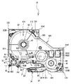
図1〜図25を参照して、一実施形態に係るテープ印字装置1およびテープカセット30について、以下に後述する。以下の説明では、図1の右下側、左上側、右上側、左下側を、それぞれテープ印字装置1の前側、後側、右側、左側とする。
A
なお、以下の説明で使用される図3、図4等において、カセット装着部8の周囲を形成する壁が図示されている場合、これらの図はあくまでも模式図であるため、図中に示す壁は、実際よりも厚く描かれている。また、図3のテープカセット30とカセット装着部8とを示す斜視図に図示されているギヤ91,93,94,97,98,101を含むギヤ群は、実際には、キャビティ811の底面により覆い隠されている。しかし、これらのギヤ群を説明する必要上、これらの図には、キャビティ811の底面は図示されていない。また、図4〜図7等において、カセット装着部8に装着された状態で図示されているテープカセット30は、上ケース311が取り外された状態のものである。
3 and 4 used in the following description, when walls forming the periphery of the
はじめに、テープ印字装置1の概略構成について説明する。テープ印字装置1は、サーマルタイプ、レセプタタイプ、ラミネートタイプ、感熱ラミネートタイプ等、各種のテープカセットが使用可能な汎用のテープ印字装置である。なお、サーマルタイプは、感熱紙テープのみが収納された種類のテープカセットである。レセプタタイプは、印字テープとインクリボンとが収納された種類のテープカセットである。ラミネートタイプは、両面粘着テープとフィルムテープとインクリボンとが収納された種類のテープカセットである。感熱ラミネートタイプは、両面粘着テープと感熱紙テープとが収納された種類のテープカセットである。
First, a schematic configuration of the
図1に示すように、テープ印字装置1は略直方体状の本体カバー2を備えている。本体カバー2の右部には、印刷データや、設定画面等を表示するためのディスプレイ5が設けられている。ディスプレイ5の左側には、文字、記号及び数字等の文字キーや、種々の機能キー等を含むキーボード3が設けられている。また、テープ印字装置1の右端側の側面には、印字済みのテープを外部に排出するための排出スリット111が設けられている(図2参照)。テープ印字装置1の背面の右部には、印字済みのテープを幅方向に切断するためのカットボタン4が設けられている。なお、人がテープ印字装置1を操作する場合は、テープ印字装置1の左側を手前にして操作する。
As shown in FIG. 1, the
一方、図2に示すように、テープ印字装置1の底面の右部には、本実施形態であるテープカセット30を着脱するために凹状に形成された平面視矩形状のカセット装着部8が設けられている。カセット装着部8は、テープの幅がそれぞれ異なる複数種類のテープカセット30を装着することができる。このカセット装着部8の左側には、乾電池を収納するための電池収納部13が隣接して設けられている。これら各部位が設けられたテープ印字装置1の底面側には、カセットカバー6(図1参照)が着脱可能に取り付けられる。
On the other hand, as shown in FIG. 2, the right side of the bottom surface of the
次に、図3〜図10を参照して、カセット装着部8について説明する。なお、以下の説明では、図3の右下側、左上側、右上側、左下側、上側、下側を、それぞれカセット装着部8とテープカセット30との前側、後側、右側、左側、上側、下側とする。
Next, the
図3に示すように、カセット装着部8は、キャビティ811と、角支持部812とを有する。キャビティ811は、テープカセット30が装着された場合に後述するカセットケース31の底面302の形状と略対応するように凹設され、平面である底面を有する。角支持部812は、キャビティ811の外縁から水平に延びる平面部である。角支持部812は、テープカセット30がカセット装着部8に装着された場合、テープカセット30の第1〜第3角部321〜323の下面に対向し、支持する部位である。
As shown in FIG. 3, the
角支持部812の2箇所に、2つの位置決めピン102,103が設けられている。より具体的には、キャビティ811の左側に位置決めピン102が、キャビティ811の右側に位置決めピン103が、それぞれ設けられている。位置決めピン102および103は、テープカセット30がカセット装着部8に装着された場合に、下ケース312に形成された2つの凹部であるピン孔62および63(図14参照)がそれぞれ対応する位置に設けられている。各位置決めピン102,103は、テープカセット30がカセット装着部8に装着された場合にピン孔62,63に挿入され、テープカセット30の周縁部の左右位置でテープカセット30を前後・左右方向に位置決めする。
Two positioning
カセット装着部8の前部には、発熱体(図示せず)を備えるサーマルヘッド10を搭載したヘッドホルダ74が固設されている。カセット装着部8の外側(図3では右上側)には、ステッピングモータであるテープ送りモータ23が配設されている。テープ送りモータ23の駆動軸の下端にはギヤ91が固着されている。ギヤ91は、開口を介してギヤ93に噛み合っている。ギヤ93は、ギヤ94に噛み合っている。ギヤ94の上面には、後述するリボン巻取スプール44(図4参照)の回転駆動を行うリボン巻取軸95が立設されている。リボン巻取軸95には、その軸体の基端側から先端側に向けて延びる複数のカム部材95Aが、平面視で放射状に設けられている(図19参照)。さらに、ギヤ94は、ギヤ97に噛み合っている。ギヤ97は、ギヤ98に噛み合っている。ギヤ98は、ギヤ101に噛み合っている。ギヤ101の上面には、後述するテープ駆動ローラ46(図4参照)の回転駆動を行うテープ駆動軸100が立設されている。テープ駆動軸100には、その軸体の基端側から先端側に向けて延びる複数のカム部材100Aが、平面視で放射状に設けられている(図19参照)。
A
テープカセット30がカセット装着部8に装着された状態でテープ送りモータ23が反時計回り方向にギヤ91を回転駆動すると、ギヤ93、ギヤ94を介して、リボン巻取軸95が反時計回り方向に回転駆動する。リボン巻取軸95は、リボン巻取軸95に装着されたリボン巻取スプール44を回転駆動する。さらに、ギヤ94の回転は、ギヤ97、ギヤ98、ギヤ101を介してテープ駆動軸100に伝達されて、テープ駆動軸100が時計回り方向に回転駆動する。テープ駆動軸100は、テープ駆動軸100に装着されたテープ駆動ローラ46を回転駆動する。ギヤ98の後側には、後述する第1テープ支持孔65に挿脱される略円柱状の第1補助軸110が立設されている。また、リボン巻取軸95の右側におけるキャビティ811の底面には、後述する第1矩形孔691に挿脱される略円柱状の第2補助軸112が立設されている(図4〜図7参照)。そのため、第2補助軸112は図3には表されていない。
When the
図4〜図7に示すように、ヘッドホルダ74の前側には、アーム状のプラテンホルダ12が軸支部121を中心に揺動可能に軸支されている。プラテンホルダ12の先端側には、サーマルヘッド10に相対して接離可能に設けられたプラテンローラ15と、テープ駆動軸100が装着されるテープ駆動ローラ46に相対して接離可能に設けられた可動搬送ローラ14とが共に回転可能に軸支されている。
As shown in FIGS. 4 to 7, an arm-shaped
プラテンホルダ12は、カセットカバー6の開閉に連動して前後方向に移動する。カセットカバー6が開放されている場合、プラテンホルダ12は、図示しない巻きバネによって、図4に示す待機位置に常に弾性付勢されている。図4に示す待機位置では、プラテンホルダ12がカセット装着部8から離間する方向に移動しているので、テープカセット30をカセット装着部8に着脱することができる。
The
カセットカバー6には、図示しない突起が立設されている。カセットカバー6が閉鎖されると、カセットカバー6の突起がプラテンホルダ12の前面を後方向に押す。これによって、プラテンホルダ12が、図5〜図7に示す印字位置に向けて移動する。図5〜図7に示す印字位置では、プラテンホルダ12がカセット装着部8に近接する方向に移動する。図5に示すように、カセット装着部8にラミネートタイプのテープカセット30が装着されている場合には、プラテンローラ15がフィルムテープ59とインクリボン60とを介してサーマルヘッド10を押圧する。同時に、可動搬送ローラ14が両面粘着テープ58とフィルムテープ59とを介してテープ駆動ローラ46を押圧する。
A projection (not shown) is erected on the cassette cover 6. When the cassette cover 6 is closed, the projection of the cassette cover 6 pushes the front surface of the
図6に示すように、レセプタタイプのテープカセット30が装着されている場合には、プラテンローラ15が印字テープ57とインクリボン60とを介してサーマルヘッド10を押圧する。同時に、可動搬送ローラ14が印字テープ57を介してテープ駆動ローラ46を押圧する。図7に示すように、サーマルタイプのテープカセット30が装着されている場合には、プラテンローラ15が感熱紙テープ55を介してサーマルヘッド10を押圧する。同時に、可動搬送ローラ14が感熱紙テープ55を介してテープ駆動ローラ46を押圧する。
As shown in FIG. 6, when the receptor
これによって、図5〜図7に示す印字位置では、カセット装着部8に装着された各種テープカセット30を使用して印字を行うことが可能となる。なお、感熱紙テープ55、印字テープ57、両面粘着テープ58、フィルムテープ59およびインクリボン60の詳細は、後述する。
As a result, at the printing position shown in FIGS. 5 to 7, printing can be performed using the
図4に示すように、テープカセット30のテープ排出部49からテープ印字装置1の排出スリット111(図2参照)までの間には、印字済テープ50が通過する経路が設けられている。この経路には、印字済テープ50を所定位置で切断するカット機構17が設けられている。カット機構17は、固定刃18と、固定刃18に対向して前後方向(図4〜図7に示す上下方向)に移動可能に支持された移動刃19と、で構成されている。なお、移動刃19は、カッターモータ24(図11参照)によって前後方向に移動される。
As shown in FIG. 4, a path through which the printed
図4および図8〜図10を参照して、ヘッドホルダ74の詳細な構成について説明する。図8〜図10に示すように、ヘッドホルダ74は、1枚の板状部材から形成されており、台座部743と、ヘッド固着部744とを備えている。台座部743は、キャビティ811の底面(図示せず)の下方に固定されている。ヘッド固着部744は、台座部743から略垂直に屈曲され、上方へ延び、且つテープ印字装置1の左右方向に沿って配置されている。カセット装着部8におけるヘッドホルダ74の配置位置は、テープカセット30が装着された場合に、後述するヘッド挿入部39に対応する位置である。ただし、ヘッドホルダ74の右端部は、ヘッド挿入部39の右端部よりも右側に延びている。サーマルヘッド10は、ヘッド固着部744の前面に固着されている(図4参照)。
A detailed configuration of the
ヘッド固着部744には、テープカセット30がテープ印字装置1に装着された場合にテープカセット30を下方から支持する第1支持部741および第2支持部742(以下、総称してカセット支持部741,742という)が設けられている。第1支持部741は、ヘッド固着部744の右端部を正面視でL字型に切り欠くことにより所定の高さ位置に形成された段差部である。第2支持部742は、第1支持部741と同一の上下方向位置(高さ位置)において、ヘッド固着部744の左端部からヘッド固着部744に対して略垂直に屈曲して延びる側面視長方形状の延設片である。
The
つまり、第1支持部741と第2支持部742とは、平面視で互いに略直交する方向に延びている。第1支持部741と第2支持部742は、それぞれ、サーマルヘッド10に対してテープ搬送方向上流側と下流側とで、同一の高さ位置でテープカセット30を支持する。第1支持部741および第2支持部742は、サーマルヘッド10の上下方向中心位置から上下方向に所定距離離れた位置に設定されている。よって、サーマルヘッド10の上下方向中心位置に対してテープカセット30を上下方向に位置決めする基準となる。なお、カセット支持部741,742によるテープカセット30の支持については、後で詳述する。
That is, the
次に、図11を参照して、テープ印字装置1の電気的構成について説明する。図11に示すように、テープ印字装置1は、制御基板上に形成される制御回路部500を備えている。制御回路部500は、各機器を制御するCPU501に、ROM502、CGROM503、RAM504、入出力インターフェース511がデータバス510を介して接続されている。
Next, the electrical configuration of the
ROM502には、CPU501がテープ印字装置1を制御するために実行する各種プログラムが記憶されている。CGROM503には、キャラクタを印字するための印字用ドットパターンデータが記憶されている。RAM504には、テキストメモリ、印字バッファ等、複数の記憶エリアが設けられている。
The
入出力インターフェース511には、キーボード3、液晶ディスプレイ(LCD)5、駆動回路506,507,508等が接続されている。駆動回路506は、サーマルヘッド10を駆動するための電子回路である。駆動回路507は、テープ送りモータ23を駆動するための電子回路である。駆動回路508は、移動刃19を動作させるカッターモータ24を駆動するための電子回路である。液晶駆動回路(LCDC)505は、ディスプレイ5に表示データを出力するためのビデオRAM(図示外)を有する。
The input /
次に、図3〜図7、図12〜図18を参照して、本実施形態に係るテープカセット30の構成について説明する。以下では、その内部に収納されるテープの種類、および、インクリボンの有無などを適宜変更することによって、前述のサーマルタイプ、レセプタタイプ、ラミネートタイプ等、各種のテープを実装可能な汎用カセットとして構成されたテープカセット30を例示する。
Next, the configuration of the
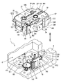
まず、テープカセット30の概略構成を説明する。図3に示すように、テープカセット30は、全体としては平面視で丸みを帯びた角部を有する箱型の筐体であるカセットケース31を有している。カセットケース31は、カセットケース31の底面302を形成する底板306を含む下ケース312と、カセットケース31の上面301を形成する上板305を含み、下ケース312の上部に固定される上ケース311とで構成される。底面302から上面301までの距離を、テープカセット30またはカセットケース31の高さという。
First, a schematic configuration of the
本実施形態のカセットケース31は、上板305および底板306の周縁全体が側面を形成する周壁によって囲われているが、必ずしも全体が囲われている必要はなく、周壁の一部(例えば背面)にカセットケース31内を露出させるような開口部が設けられていたり、その開口部を臨む位置に上板305および底板306を接続するボスが設けられたりしてもよい。
In the
カセットケース31は、テープカセット30の種類にかかわらず、同一の幅(上下方向の長さが同一)に形成された3つの角部を有する。以下では、左前方の角部を第1角部321、左後方の角部を第2角部322、右前方の角部を第3角部323とする。第1角部321と第2角部322と第3角部323とは、平面視で直角をなすようにカセットケース31の側面から外側方向に突出している。ただし、左前方の第1角部321は、テープ排出部49が角に設けられているために、直角はなしていない。第1角部321と第2角部322と第3角部323との下面は、テープカセット30がカセット装着部8に装着されたときに、前述した角支持部812に対向する部位である。
The
図12〜図14に示すように、第1角部321におけるカセットケース31の左側面、且つテープ排出部49の近傍には、上板305から底板306に亘ってカセットケース31の内側方向に凹んだ凹部である第1凹部325が設けられている。また、カセットケース31の右後方には、カセットケース31の右側面の後部が、上板305から底板306に亘ってカセットケース31の内側方向に凹んだ凹部である第2凹部326が設けられている。つまり、第1凹部325と第2凹部326とは、テープカセット30の対角に設けられている。
As shown in FIGS. 12 to 14, the
図4〜図7に示すように、第2凹部326を形成する壁の一部は、後述する第2テープスプール41の周囲に設けられるテープロールが配置される領域の一部に沿って形成された円弧状壁326A(図12参照)である。円弧状壁326Aは、テープロールの径外側への広がりを規制する。これによって、第2凹部326を形成する壁と、テープロールが配置される領域を規定する壁とを別々に形成する場合と比べて、材料を少なくして、テープカセットのコストダウンをすることができる。
As shown in FIGS. 4-7, a part of wall which forms the 2nd recessed
図14に示すように、第1角部321と第2凹部326の前側との下面の2箇所に、前述したテープ印字装置1の位置決めピン102,103に対応するピン孔62,63が設けられている。より具体的には、第1角部321の下面に設けられた凹部が、位置決めピン102が挿入されるピン孔62である。第2凹部326の前側の下面に設けられた凹部が、位置決めピン103が挿入されるピン孔63である。
As shown in FIG. 14, pin holes 62 and 63 corresponding to the positioning pins 102 and 103 of the
図3、図4、および図12に示すように、テープカセット30の平面視中央からみた左後側には、第1テープスプール40を回転可能に支持する第1テープ支持孔65が形成されている。テープカセット30の平面視中央からみた右後側には、第2テープスプール41を回転可能に支持する第2テープ支持孔66が形成されている。テープカセット30の平面視中央からみた右前側には、リボンスプール42を回転可能に支持するリボン支持孔67が形成されている。第1テープ支持孔65とリボン支持孔67との間には、リボンスプール42からインクリボン60を引き出すとともに、文字等の印字にて使用されたインクリボン60を巻き取るリボン巻取スプール44を回転可能に支持する巻取支持孔68が形成されている。巻取支持孔68の右側、且つ第2凹部326の前側には、それぞれ平面視矩形形状をした第1矩形孔691と第2矩形孔692とが、左右方向に並んで形成されている。第1矩形孔691は、第2矩形孔692の右側に設けられている。詳細は後述するが、第1矩形孔691には、第2補助軸112が挿入される。
As shown in FIGS. 3, 4, and 12, a first
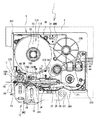
図4および図5に示すラミネートタイプのテープカセット30では、カセットケース31内に、一面に剥離紙が貼着された両面粘着テープ58、印字媒体である透明なフィルムテープ59、およびインクリボン60の3種類のテープロールが収納される。両面粘着テープ58が剥離紙を外側に向けて巻回された両面粘着テープロール581は、第1テープスプール40の周囲に設けられている。フィルムテープ59が巻回されたフィルムテープロール591は、第2テープスプール41の周囲に設けられている。未使用のインクリボン60が巻回されたインクリボンロール601は、リボンスプール42の周囲に設けられている。使用済みのインクリボン60は、リボン巻取スプール44に巻き取られる。リボン巻取スプール44の下部には、リボン巻取スプール44が逆転することで巻き取ったインクリボン60が緩んでしまうのを防止するためのクラッチバネ(図示せず)が取り付けられている。
4 and 5, a double-sided pressure-
図6に示すレセプタタイプのテープカセット30では、印字媒体である印字テープ57と、インクリボン60の2種類のテープロールが、カセットケース31内に収納される。印字テープ57が巻回された印字テープロール571は、第1テープスプール40の周囲に設けられている。未使用のインクリボン60が巻回されたインクリボンロール601は、リボンスプール42の周囲に設けられている。レセプタタイプのテープカセット30は、第2テープスプール41を備えていない。
In the receptor
図7に示すサーマルタイプのテープカセット30では、感熱紙テープ55の1種類のテープロールが、カセットケース31内に収納される。感熱紙テープ55が巻回された感熱紙テープロール551は、第1テープスプール40の周囲に設けられている。サーマルタイプのテープカセット30は、第2テープスプール41およびリボンスプール42を備えていない。以下では、印字媒体である感熱紙テープ55、印字テープ57、フィルムテープ59のいずれかを指す場合、単にテープという。
In the thermal
図3および図12に示すように、上ケース311における第1テープ支持孔65と第2テープ支持孔66との間には、左右方向に長い矩形状の孔である残量確認孔70が設けられている。つまり、残量確認孔70は、第1テープスプール40と第2テープスプール41との周囲にそれぞれ設けられたテープロールを臨むように設けられている。これによって、人は、第1テープスプール40と第2テープスプール41との周囲にそれぞれ設けられたテープロールの残量を確認することができる。
As shown in FIGS. 3 and 12, a remaining
図3に示すように、カセットケース31の前面には、平面視で略半円状をなす溝部である半円溝340が、カセットケース31の高さ方向(つまり、上面301から底面302)に亘って設けられている。半円溝340は、テープカセット30がカセット装着部8に装着されたときに、プラテンホルダ12の回転中心である軸支部121がカセットケース31と干渉しないように設けられた逃がし部である。
As shown in FIG. 3, a
カセットケース31の前面壁のうち、半円溝340から左に延びる部分を、アーム前面壁35という。アーム前面壁35と、アーム前面壁35から後方へ離間した位置に高さ方向に亘って設けられたアーム背面壁37とで規定される、テープカセット30の右側から左方に延びる部位をアーム部34という。アーム前面壁35の左端部は、後方へ向かって屈曲しており、アーム前面壁35およびアーム背面壁37の左端の間に形成される上下方向に延びる隙間が、アーム部34からテープ(およびインクリボン60)を排出する排出口341である。
A portion of the front wall of the
図4〜図7に示すように、アーム部34では、第1テープスプール40または第2テープスプール41から引き出されたテープが、アーム前面壁35と略平行に延びる搬送経路に沿って案内され、排出口341から排出される。また、リボンスプール42から引き出されたインクリボン60は、テープとは異なる搬送経路に沿ってアーム部34内を案内され、排出口341でテープと重なった状態とされて排出される。
As shown in FIGS. 4 to 7, in the
アーム背面壁37と、アーム背面壁37から連続して設けられたヘッド周壁373とにより規定される、テープカセット30を上下方向に貫通する平面視略長方形状の空間は、ヘッド挿入部39である。ヘッド挿入部39は、テープカセット30の前面に設けられた開口部77によって、テープカセット30の前面で外部とつながっている。ヘッド挿入部39には、テープ印字装置1のサーマルヘッド10を支持するヘッドホルダ74が挿入される。アーム部34の排出口341から排出されたテープには、開口部77(図4〜図7参照)において、インクリボン60を用いてサーマルヘッド10による印字が行われる。
A substantially rectangular space in plan view that penetrates the
図4〜図7、図13、および図14に示すように、下ケース312のヘッド挿入部39の外周上でヘッド挿入部39を臨む位置には、テープカセット30がテープ印字装置1に装着される際の上下方向の位置決めに使用される支持受け部が設けられている。具体的には、サーマルヘッド10(図4〜図7参照)の挿入位置(より詳細には印字位置)を基準として、テープの搬送方向上流側および下流側の2箇所に、第1受け部391および第2受け部392(以下、総称して支持受け部391,392という)が設けられている。
As shown in FIGS. 4 to 7, 13, and 14, the
第1受け部391は、アーム部34のテープ搬送方向上流側の端部、およびヘッド挿入部39の上流側端部に連接している。第2受け部392は、ヘッド挿入部39の下流側端部に連接している。第1受け部391および第2受け部392は、いずれも底板306の底面302を上方に向かって凹ませた凹部である。また、第1受け部391は、アーム前面壁35に沿った方向にヘッド挿入部39から凹んでいる。第2受け部392は、アーム前面壁35に対して直交する方向にヘッド挿入部39から凹んでいる。つまり、第1受け部391と第2受け部392とは、互いに直交する方向でヘッド挿入部39を臨んでいる。
The
第1受け部391および第2受け部392は、それぞれ底面302より上方に位置する底面視略長方形状の平面部(凹部の底部分)の下側の面である第1下側平面部391Bおよび第4下側平面部392Bを有する。下ケース312の上下方向(高さ方向)における第1,第4下側平面部391B,392Bの位置と、カセットケース31に収納されるテープおよびインクリボン60の幅方向中心位置とは、テープカセット30の種類にかかわらず、つまり、テープカセット30の上下方向の高さが異なっていても一定である。よって、収納されるテープおよびインクリボン60の幅がより広いテープカセット30ほど、底面302に設けられた凹部である支持受け部391,392の深さは大きくなる。
The
第1,第4下側平面部391B,392Bは、テープおよびインクリボン60の幅方向中心位置から上下方向に同一の距離だけ離れた位置にある。つまり、第1,第4下側平面部391B,392Bは、下ケース312において同一の高さ位置にある。本実施形態では、テープおよびインクリボン60の幅方向中心位置と、カセットケース31の上下方向中心位置とは一致している。
The first and fourth lower
第1,第4下側平面部391B,392Bはテープカセット30がカセット装着部8に装着された場合、それぞれ、ヘッドホルダ74に設けられたカセット支持部741,742によって下方から支持される部位として機能する。
The first and fourth lower
図3に示すように、テープの搬送方向において、ヘッド挿入部39の下流側には、上下一対の規制部材361,362が設けられている。規制部材361,362は、排出口341から排出され、印字がなされた後のテープを、サーマルヘッド10の下流側でテープ排出部49に向かって案内する。詳細は後述するが、印字に使用されたインクリボン60は、規制部材361,362の上流側でテープとは分離され、別の搬送経路に沿って搬送され、リボン巻取スプール44に巻き取られる。
As shown in FIG. 3, a pair of upper and lower regulating
図13に示すように、ヘッド周壁373のうち、テープの搬送方向においてヘッド挿入部39の下流側端部を規定する左側壁を、リボン案内壁38という。リボン案内壁38は、規制部材362の上流側に隣接している。インクリボン60の搬送経路は、インクリボンロール601からアーム部34、開口部77を経由して、リボン巻取スプール44に至る。リボン案内壁38は、開口部77で印字に使用されたインクリボン60を、搬送経路に沿って屈曲させ、リボン巻取スプール44に向かって案内する。ヘッド挿入部39の下流側端部に連接して設けられた第2受け部392は、リボン案内壁38からリボン巻取スプール44に至るインクリボン60の搬送経路よりも前方に位置する。
As shown in FIG. 13, the left side wall of the head
リボン案内壁38とリボン巻取スプール44との間には、分離壁48が立設されている。分離壁48は、リボン案内壁38に沿って案内される使用済みのインクリボン60と、第1テープスプール40の周囲に設けられた両面粘着テープロール581とが互いに接触するのを防止する。
A
図12に示すように、テープの搬送経路のうち、テープ排出部49の近傍、且つテープ排出部49に対してテープの搬送経路の上流側には、テープがカセットケース31の外部に露出した部分であるテープ露出部78が設けられている。テープ露出部78の後側には、ローラ支持孔64が設けられ、ローラ支持孔64の内側にテープ駆動ローラ46が回転可能に軸支されている。つまり、テープ露出部78の後側に隣接して、テープをテープ排出口に搬送するテープ駆動ローラ46が設けられている。テープ駆動ローラ46は、上下方向を軸方向として配置された筒状部材であり、テープ駆動ローラ46を上下方向に貫通した孔である軸孔46D(図17参照)を備えている。つまり、軸孔46Dは、テープカセット30の左前部に設けられている。
As shown in FIG. 12, the portion of the tape transport path that is exposed to the outside of the
図4および図5に示すラミネートタイプのテープカセット30がカセット装着部8に装着されている場合は、テープ駆動ローラ46が、対向する可動搬送ローラ14との協働により、フィルムテープロール591からフィルムテープ59を引き出すとともに、両面粘着テープロール581から両面粘着テープ58を引き出す。さらに、両面粘着テープ58をフィルムテープ59の印字面にガイドして接着させ、印字済テープ50としてテープ排出部49に向かって搬送する。
When the laminate
図6に示すレセプタタイプのテープカセット30がカセット装着部8に装着されている場合は、テープ駆動ローラ46と可動搬送ローラ14との協働により、印字テープロール571から印字テープ57が引き出される。サーマルヘッド10の下流側では、印字後の印字テープ57、すなわち印字済テープ50が、規制部材361,362によって、テープ排出部49に向かって案内される。また、ヘッド挿入部39を経由して搬送された使用済みのインクリボン60は、規制部材361,362の上流で印字テープ57から分離され、リボン巻取スプール44に向かって搬送される。
When the receptor
図7に示すサーマルタイプのテープカセット30が装着されている場合は、テープ駆動ローラ46と可動搬送ローラ14との協働により、感熱紙テープロール551から感熱紙テープ55が引き出される。サーマルヘッド10の下流側では、印字後の感熱紙テープ55、すなわち印字済テープ50が、規制部材361,362によって、テープ排出部49に向かって案内される。
When the thermal
図3および図13に示すように、テープ排出部49は、カセットケース31の左側面の前端部から僅かに前方に離間して設けられた、上面301と底面302に亘る板状部材である。テープ排出部49は、規制部材361,362およびテープ駆動ローラ46を経て搬送されてきた印字済テープ50を、カセットケース31の左側面の前端部との間に形成される通路内に案内して、通路の終端にあるテープ排出口から排出する。
As shown in FIG. 3 and FIG. 13, the
テープ排出部49には、印字済テープ50にそれぞれ対向する一対の内面491,492が設けられている。内面491,492は、印字済テープ50の面に直交する方向(つまり、前後方向)への印字済テープ50の移動を制限する。このため、人がテープカセット30を第1凹部325と第2凹部326とに指を添えて把持した場合に、第1凹部325に添えられた指に印字済テープ50が触れるおそれが低くなる。よって、例えば、印字済テープ50に指が触れて、印字済テープ50に汚れが付着するおそれが低くなる。
The
次に、下ケース312における第2,第3角部322,323について説明する。図13に示すように、下ケース312は、第2角部322の下面である第2下側平面部322B、および第3角部323の下面である第3下側平面部323Bを含む。第2下側平面部322Bおよび第3下側平面部323Bは、いずれも底面302よりも上方に位置する平面部である。
Next, the second and
下ケース312の上下方向(高さ方向)における第2,第3下側平面部322B,323Bの位置と、テープおよびインクリボン60の幅方向中心位置とは、テープカセット30の種類にかかわらず、つまりテープカセット30の上下方向の高さが異なっていても一定である。よって、収納されるテープおよびインクリボン60の幅がより広いテープカセット30ほど、底面302から第2,第3下側平面部322B,323Bまでの距離は大きくなる。
Regardless of the type of the
本実施形態では、前述の第1,第4下側平面部391B,392B、および第2,第3下側平面部322B,323Bは、テープおよびインクリボン60の幅方向中心位置(本実施形態では、カセットケース31の上下方向中心位置)から上下方向に同一の距離だけ離れた位置にある。つまり、第1,第4,第2,第3下側平面部391B,392B,322B,323Bは、下ケース312においてすべて同一の高さ位置にある。
In the present embodiment, the first and fourth lower
次に、図15〜図18を参照して、テープカセット30に形成される孔部(第1テープ支持孔65、巻取支持孔68、ローラ支持孔64、第1,第2矩形孔691,692)、および、これらの孔部に関連する部材について説明する。
Next, referring to FIGS. 15 to 18, holes formed in the tape cassette 30 (first
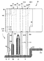
図15に示すように、第1テープスプール40は、カセットケース31を上下方向に貫通する第1テープ支持孔65を介して回転可能に支持されている。詳細には、第1テープ支持孔65は、上板305および底板306から互いに対向する方向にそれぞれ延設される凹陥孔である開口部65Aおよび開口部65Bと、開口部65A,65B間を連通する軸孔65Cとを備えている。上ケース311は、開口部65Aから底板306に向けて延設され、平面視で開口部65Aの中心から放射状に複数の係止リブ84を備える。各係止リブ84は、それぞれの先端側がカセットケース31の内部で互いに対向する方向に突起する鉤状体である。下ケース312は、開口部65Bから上板305に向けて延設される円筒状の筒壁部85を備える。筒壁部85には、その上下方向に切り込まれた複数のスリット87が、平面視で開口部65Bの中心から放射状に形成される。筒壁部85における各スリット87の上端側には、各スリット87の開口端を閉じるための頭部86がそれぞれ設けられている。カセットケース31の内部では、筒壁部85の先端側に設けられた各頭部86に、それぞれ対応する係止リブ84が各スリット87を介して係止されている。なお、筒壁部85の内部では、カセットケース31を上下方向に貫通する軸孔65Cが開口部65A,65Bを連通させる。
As shown in FIG. 15, the
第1テープスプール40は、内壁40Aと外壁40Bとの二重壁構造を有する。内壁40Aは、筒壁部85の外径よりも若干内径が大きい円筒体であり、第1テープスプール40の周囲に設けられるテープや両面粘着テープ58の幅よりも小さい高さ寸法を有する。内壁40Aの内部には、その上下方向に貫通する軸孔40Dが形成されている。外壁40Bは、内壁40Aの径外側に設けられて内壁40Aを全周に亘って取り囲む円筒体であり、テープや両面粘着テープ58の幅とほぼ同一の高さ寸法を有する。図4および図5に示すラミネートタイプのテープカセットの場合、外壁40Bの外周面には、両面粘着テープロール581が備えられている。内壁40Aと外壁40Bとの間には、上下方向を長手とする板状部材である連結体40Cが、平面視で内壁40Aおよび外壁40Bの中心から放射状に架設されている。第1テープスプール40は、これらの連結体40Cによって内壁40Aおよび外壁40Bが同軸をなす二重筒状に構成される。第1テープスプール40は、軸孔40Dに挿入された筒壁部85によって軸支されつつ、カセットケース31内で軸線中心に回転自在となる。
The
図16に示すように、リボン巻取スプール44は、カセットケース31を上下方向に貫通する巻取支持孔68を介して回転可能に支持されている。詳細には、巻取支持孔68は、上板305および底板306において互いに対向する位置にそれぞれ形成される貫通孔である開口部68Aおよび開口部68Bを備えている。リボン巻取スプール44は、カセットケース31の幅長(つまり、上下方向の長さ)とほぼ等しい高さ寸法を有する円筒状をなす。リボン巻取スプール44の外周面における上端縁および下端縁には、それぞれ径外方向の全周に亘って突出するフランジ状の支持部44Eが設けられている。
As shown in FIG. 16, the ribbon take-up
カセットケース31の内部では、上端部44Aが上板305の開口部68Aに嵌合されるとともに、下端部44Bが底板306の開口部68Bに嵌合されている。リボン巻取スプール44の上端縁に設けられた支持部44Eは、上ケース311に下方から接触してリボン巻取スプール44の上方向への移動を規制する。リボン巻取スプール44の下端縁に設けられた支持部44Eは、下ケース312に上方から接触してリボン巻取スプール44の下方向への移動を規制する。これにより、リボン巻取スプール44は、両端部44A,44Bにて支持されつつ、カセットケース31内で軸線中心に回転自在となる。
Inside the
リボン巻取スプール44の内部には、その上下方向に貫通する軸孔44Cが形成されている。リボン巻取スプール44の内周面(つまり、軸孔44Cを形成する内壁)には、その上下方向の中央位置から若干下方に複数の係合リブ44Dが設けられている。テープカセット30がカセット装着部8に装着されると、前述のリボン巻取軸95が開口部68Bを介して軸孔44Cに挿入される。そして、リボン巻取スプール44に設けられた複数の係合リブ44Dに、リボン巻取軸95の周囲に形成された複数のカム部材95Aが噛合される。これにより、リボン巻取軸95の回転がリボン巻取スプール44に伝達される。つまり、リボン巻取軸95の回転に伴ってリボン巻取スプール44が回転する。
A
図17に示すように、テープ駆動ローラ46は、カセットケース31を上下方向に貫通するローラ支持孔64を介して回転可能に支持されている。詳細には、ローラ支持孔64は、上板305および底板306において互いに対向する位置にそれぞれ形成される貫通孔である開口部64Aおよび開口部64Bを備えている。開口部64A,64Bの各近傍位置には、前述した一対の規制部材361,362が形成されている。一対の規制部材361,362の後側には、一対の規制部材361,362と隣接してリボン案内壁38が上ケース311と下ケース312とに亘って立設されている。一対の規制部材361,362の基端の間隔幅は、テープの幅と同一に設定されている。
As shown in FIG. 17, the
テープ駆動ローラ46は、カセットケース31の幅長(つまり、上下方向の長さ)とほぼ等しい高さ寸法を有する円筒状をなす。テープ駆動ローラ46の本体部46Eは、開口部64A,64Bよりも径が大きく、その外周面がテープ等に接触するローラ面46Cである。ローラ面46Cの上下方向長さ(つまり、テープ駆動ローラ46におけるテープ送り幅)は、テープの幅と同一に設定されている。テープ駆動ローラ46の本体部46Eから上下方向にそれぞれ突出する上端部46Aおよび下端部46Bは、それぞれ開口部64A,64Bよりも径が若干小さい。なお、テープ駆動ローラ46の内部では、本体部46Eを上下方向に貫通する軸孔46Dが両端部46A,46Bを連通させる。
The
カセットケース31の内部では、上端部46Aが上板305の開口部64Aに嵌合されるとともに、下端部46Bが底板306の開口部64Bに嵌合されている。本体部46Eは、上ケース311に下方から接触してテープ駆動ローラ46の上方向への移動を規制し、下ケース312に上方から接触してテープ駆動ローラ46の下方向への移動を規制する。これによって、テープ駆動ローラ46は、両端部46A,46Bにて支持されつつ、カセットケース31内で軸線中心に回転自在となる。
Inside the
テープ駆動ローラ46の内周面(つまり、軸孔46Dを形成する内壁)には、その下端側に複数の係合リブ46F(図24参照)が設けられている。テープカセット30がカセット装着部8に装着されると、前述のテープ駆動軸100が開口部64Bを介して軸孔46Dに挿入される。そして、テープ駆動ローラ46に設けられた複数の係合リブ46Fに、テープ駆動軸100の周囲に形成された複数のカム部材100A(図19および図24参照)が噛合される。これによって、テープ駆動軸100の回転がテープ駆動ローラ46に伝達される。つまり、テープ駆動軸100の回転に伴ってテープ駆動ローラ46が回転する。
A plurality of
図18に示すように、第1矩形孔691は、上板305および底板306から互いに対向する方向にそれぞれ延設される凹陥孔である開口部691Aおよび開口部691Bと、開口部691A,691Bを連通させる軸孔691Cとを備えている。第2矩形孔692は、上板305および底板306から互いに対向する方向にそれぞれ延設される凹陥孔である開口部692Aおよび開口部692Bと、開口部692A,692Bを連通させる軸孔692Cとを備えている。軸孔691Cと軸孔692Cとの互いに対向する面には、それぞれ開口部691D,692Dが設けられている。軸孔691Cと軸孔692Cとの互いに対向する面の間には、図4〜図7に示すようにテープの搬送経路が設けられている。
As shown in FIG. 18, the first
図12および図14に示すように、第2テープ支持孔66は、上板305および底板306において互いに対向する位置にそれぞれ形成される一対の開口部66A,66Bを備えている。各開口部66A,66Bは、カセットケース31の内部にそれぞれ対向する方向に陥入する凹部に連設されている。第2テープスプール41は、印字媒体のテープ幅とほぼ同一の高さ寸法を有する円筒体である。ラミネートタイプのテープカセット30の場合には、第2テープスプール41の外周にフィルムテープロール591が設けられている(図4および図5参照)。カセットケース31内にフィルムテープロール591を収納する場合は、第2テープスプールを上下方向に貫通する軸孔が有する両端開口に、各開口部66A,66Bから連設される凹部がそれぞれ挿入される。これにより、第2テープスプール41は、第2テープ支持孔66にて軸支されつつ、カセットケース31内で軸線中心に回転自在となる。なお、図6および図7に示すレセプタタイプおよびサーマルタイプのテープカセット30は、第2テープスプール41を備えていない。
As shown in FIGS. 12 and 14, the second
同様に、リボン支持孔67も、上板305および底板306において互いに対向する位置にそれぞれ形成される一対の開口部67A,67Bを備えている。各開口部67A,67Bは、カセットケース31の内部にそれぞれ対向する方向に陥入する凹部に連設されている。リボンスプール42は、テープの幅とほぼ同一の高さ寸法を有する円筒体であって、その外周面にインクリボン60が巻回される。カセットケース31内にインクリボン60を収納する場合は、リボンスプール42の上下方向に貫通する軸孔が有する両端開口に、各開口部67A,67Bから連設される凹部がそれぞれ挿入される。これにより、リボンスプール42は、リボン支持孔67にて軸支されつつ、カセットケース31内で軸線中心に回転自在となる。なお、図7に示すサーマルタイプのテープカセット30は、リボンスプール42を備えていない。
Similarly, the
ここで、本実施形態における、テープカセット30に設けられた第1矩形孔691、第1テープ支持孔65、第2テープ支持孔66、巻取支持孔68、リボン支持孔67の位置関係について、図12を参照して詳細に説明する。前述のローラ支持孔64、第1矩形孔691、第1テープ支持孔65、巻取支持孔68は、テープカセット30が装着されるカセット装着部8のテープ駆動軸100、第2補助軸112、第1補助軸110、リボン巻取軸95と対向する位置にそれぞれ形成されている。
Here, regarding the positional relationship of the first
図12に示すように、第1角部321は、テープカセット30の左前部に設けられている。第2凹部326は、テープカセット30の右後部に設けられている。第1角部321(より詳細には、第1角部321に設けられたテープ排出部49)と第2凹部326とを平面視で結ぶ分割線Kを基準としてテープカセット30を平面視で分割した場合に、分割線Kよりも後側を占めるのが第1収納領域30Cであり、分割線Kよりも前側を占めるのが第2収納領域30Dである。第1矩形孔691と軸孔46Dと第1テープ支持孔65とのそれぞれの中心を結んだ線によって囲まれる領域を、特定領域350という。
As shown in FIG. 12, the
第1テープ支持孔65は、平面視で三角形状をなす第1収納領域30Cの重心(つまり、第1収納領域30Cを形成する3辺の中線を結ぶ交点)またはその近傍に形成される。巻取支持孔68は、平面視で三角形状をなす第2収納領域30Dの重心(つまり、第2収納領域30Dを形成する3辺の中線を結ぶ交点)またはその近傍に形成される。また、ここでは、第1テープ支持孔65および巻取支持孔68は、平面視で分割線Kを中心としてほぼ対称に位置している。
The first
第2テープ支持孔66は平面視で分割線K上に形成されており、詳細にはテープカセット30の平面視中央と第2凹部326との略中間に位置している。リボン支持孔67は第2収納領域30Dに形成されており、詳細には巻取支持孔68よりもテープカセット30の右前側に位置している。
The second
上記のような位置関係において、図4〜図7に示すテープカセット30の重心の位置は次のようになる。図4および図5に示すラミネートタイプのテープカセット30の場合、両面粘着テープロール581、フィルムテープロール591、インクリボンロール601のうち、最も重量が大きいのは、両面粘着テープロール581である。また、前述したように、第1テープ支持孔65(図3参照)では、テープカセット30の内部で、両面粘着テープロール581を周囲に備えた第1テープスプール40が回転支持されている。これは、両面粘着テープロール581における両面粘着テープ58の巻回中心が、平面視で、第1収納領域30C(図12参照)の範囲内、且つ特定領域350(図12参照)を形成する一の頂点に位置していることを示している。言い換えると、最も重量の大きい両面粘着テープロール581の重心が、平面視で、第1収納領域30Cの範囲内、且つ特定領域350に位置している。これによって、テープカセット30全体の重心は、特定領域350の範囲に位置している。
In the above positional relationship, the position of the center of gravity of the
また、両面粘着テープロール581とインクリボンロール601とリボン巻取スプール44とは、第2角部322と第3角部323とを結んだ線上に配置されている。つまり、両面粘着テープロール581とインクリボンロール601とリボン巻取スプール44とは、第1角部321と第2凹部326とを結んだ対角線と交差する他の対角線上に配置されている。このため、テープカセット30の重心は、第2角部322と第3角部323とを結んだ線の近傍に位置する。この場合、人が第1凹部と第2凹部とに指を添えてテープカセット30を把持すれば、重心位置を挟んで把持することができ、人は、テープカセット30の位置を正確に操作することができる。
The double-sided
図6に示すレセプタタイプのテープカセット30の場合、印字テープロール571とインクリボンロール601とのうち、最も重量が大きいのは、印字テープロール571である。また、前述したように、第1テープ支持孔65では、テープカセット30の内部で、印字テープロール571を周囲に備えた第1テープスプール40が回転支持されている。これは、印字テープロール571における印字テープ57の巻回中心が、平面視で、第1収納領域30C(図12参照)の範囲内、且つ特定領域350(図12参照)を形成する1の頂点に位置していることを示している。言い換えると、最も重量が大きい印字テープロール571の重心が、平面視で、第1収納領域30Cの範囲内、且つ特定領域350に位置している。これによって、テープカセット30全体の重心は、特定領域350に位置している。
In the case of the receptor
また、印字テープロール571とインクリボンロール601とリボン巻取スプール44とは、第2角部322と第3角部323とを結んだ線上に配置されている。つまり、印字テープロール571とインクリボンロール601とリボン巻取スプール44とは、第1角部321と第2凹部326とを結んだ対角線と交差する他の対角線上に配置されている。このため、テープカセット30の重心は、第2角部322と第3角部323とを結んだ線の近傍に位置する。この場合、人が第1凹部と第2凹部とに指を添えてテープカセット30を把持すれば、重心位置を挟んで把持することができ、人は、テープカセット30の位置を正確に操作することができる。
The
図7に示すサーマルタイプのテープカセット30の場合、前述したように、第1テープ支持孔65では、テープカセット30の内部で、感熱紙テープロール551を周囲に備えた第1テープスプール40が回転支持されている。これは、感熱紙テープロール551における感熱紙テープ55の巻回中心が、平面視で、第1収納領域30C(図12参照)の範囲内、且つ特定領域350(図12参照)を形成する一の頂点に位置していることを示している。言い換えると、感熱紙テープロール551の重心が、平面視で、第1収納領域30Cの範囲内、且つ特定領域350に位置している。これによって、テープカセット30全体の重心位置は、特定領域350の範囲に位置している。
In the case of the thermal
上記説明したテープ印字装置1およびテープカセット30では、テープカセット30がカセット装着部8に装着される場合、カセット装着部8に立設された3つの案内軸(テープ駆動軸100、第1補助軸110、第2補助軸112)とヘッドホルダ74とが、テープカセット30に設けられた3つの案内孔(ローラ支持孔64、第1テープ支持孔65、第1矩形孔691)とヘッド挿入部39とにそれぞれ案内され、テープカセット30がカセット装着部8の適正位置に装着される。
In the
ここで、本実施形態における、カセット装着部8に対するテープカセット30の着脱態様について、図19〜図25を参照して説明する。図19、図20、および図22では、テープカセット30の右側面を示しているが、理解を容易にするためにテープカセット30の着脱に関する孔部等を仮想線(二点鎖線)で示している。また、カセット装着部8を右側からみた概略断面を示しているが、理解を容易にするためにテープカセット30の着脱に関する軸部のみを図示している。また、理解を容易にするため、3つの案内孔(ローラ支持孔64、第1テープ支持孔65、第1矩形孔691)とヘッド挿入部39と巻取支持孔68とが重ならないようにそれぞれの位置をずらして示している。同様に、3つの案内軸(テープ駆動軸100、第1補助軸110、第2補助軸112)とヘッドホルダ74とリボン巻取軸95とが重ならないように、ぞれぞれの位置をずらして示している。また、図21および図23では、テープカセット30の正面を示しているが、理解を容易にするために、テープカセット30のヘッド挿入部39の左右の端部を仮想線(二点鎖線)で示している。また、図21および図23においては、サーマルヘッド10の図示は省略している。
Here, the attachment / detachment aspect of the
まず、カセット装着部8に立設された各部材の高さ関係について説明する。図19に示すように、ヘッドホルダ74、テープ駆動軸100、リボン巻取軸95、第1補助軸110、第2補助軸112のうち、3つの案内軸(テープ駆動軸100、第1補助軸110、第2補助軸112)は、それぞれの軸長が略等しい。さらに、テープ駆動軸100、第1補助軸110および第2補助軸112の各軸長は、リボン巻取軸95の軸長およびヘッドホルダ74の縦サイズよりも大きい。そのため、ヘッドホルダ74、テープ駆動軸100、リボン巻取軸95、第1補助軸110、および第2補助軸112のうち、テープ駆動軸100、第1補助軸110、および第2補助軸112の上端における高さ位置が最も大きく、次いでヘッドホルダ74の上端における高さ位置が大きく、リボン巻取軸95の上端における高さ位置が最も小さい。ただし、リボン巻取軸95の上端における高さ位置は、ヘッドホルダ74に固着されているサーマルヘッド10の上端における高さ位置とほぼ等しくなっている。
First, the height relationship of each member erected on the
図19に示すように、ユーザがテープカセット30をカセット装着部8に装着する場合は、ローラ支持孔64、第1テープ支持孔65、第1矩形孔691、およびヘッド挿入部39をそれぞれテープ駆動軸100、第1補助軸110、第2補助軸112、およびヘッドホルダ74に対して平面視での相対位置をほぼ一致させ、前述したように上板305および底板306を略水平に維持しつつ垂直に嵌め込む。
As shown in FIG. 19, when the user mounts the
テープカセット30をカセット装着部8に向けて下方に移動させると、図20に示すようにテープ駆動軸100、第1補助軸110、第2補助軸112の各上端が、テープカセット30の底板306に設けられた開口部64B,65B,691Bにほぼ同時にそれぞれ進入する。一方、ヘッドホルダ74およびリボン巻取軸95は、それぞれの上端が底板306の下方に位置している状態であるため、テープカセット30の内部に進入していない。
When the
図20に示す状態から、テープカセット30をさらに下方に移動させると、テープ駆動軸100、第1補助軸110、第2補助軸112はそれぞれ開口部64B,65B,691Bを介して軸孔46D,65C,691Cに下方から挿入される。軸孔46D,65C,691Cの内部では、それぞれに挿入されたテープ駆動軸100、第1補助軸110、第2補助軸112が、各軸孔46D,65C,691Cの内壁によって周方向への移動が規制され、その立設方向(つまり、上下方向)に沿って摺動可能な状態となる。言い換えると、テープカセット30は、軸孔46D,65C,691Cにそれぞれ挿入されるテープ駆動軸100、第1補助軸110、第2補助軸112の立設方向に沿って案内されつつ、自重の作用も加わって下方に移動する。このとき、テープカセット30の重心が、軸孔46Dと第1テープ支持孔65と第1矩形孔691とのそれぞれの中心を結んだ線によって形成される領域である特定領域350にあるため、バランス良くテープ駆動軸100、第1補助軸110、第2補助軸112に案内される。このため、テープカセット30が傾くおそれが低い。
When the
なお、テープ駆動軸100、第1補助軸110、第2補助軸112の上端縁は、その上端に向けて軸径が小さくなるようなテーパ形状となっている。そのため、ローラ支持孔64、第1テープ支持孔65、第1矩形孔691に対して平面視での相対位置に若干ズレが生じていても、テープ駆動軸100、第1補助軸110、第2補助軸112を適切かつ円滑に挿入可能である。
The upper end edges of the
また、リボン巻取軸95は、開口部68Bを介して軸孔44Cに下方から挿入される。そして、開口部68Bおよび軸孔44Cは、リボン巻取軸95に案内される。
The ribbon take-up
一方、図20に示す位置から、テープカセット30が下方に案内されるのに伴って、図21に示すように、ヘッドホルダ74がヘッド挿入部39に下方から挿入される。テープカセット30をヘッドホルダ74、テープ駆動軸100、第1補助軸110、第2補助軸112に沿って、さらに下方に移動させていくと、図22に示すように、角支持部812上に立設された位置決めピン103がピン孔63内に挿入される。同時に、図22に図示しないが、角支持部812上に立設された位置決めピン102がピン孔62に挿入される。また、図22および図23に示すように、カセット支持部741,742が、第1,第4下側平面部391B,392Bに接触し、位置決めされる。また、第2,第3下側平面部322B,323Bが、角支持部812に対向し、支持される。つまり、カセット装着部8に装着されたテープカセット30の高さ位置は、カセット支持部741,742、角支持部812等によって支持される高さ位置に規定される。
On the other hand, as the
また、位置決めピン102,103はそれぞれ、ピン孔62,63の内部で係止されて、位置決めピン102,103の周方向への変位が規制される。つまり、カセット装着部8に装着されたテープカセット30の平面位置は、位置決めピン102,103によって係止される平面位置に規定される。
Further, the positioning pins 102 and 103 are locked inside the pin holes 62 and 63, respectively, and displacement of the positioning pins 102 and 103 in the circumferential direction is restricted. That is, the planar position of the
このように、本実施形態では、テープカセット30が3つの案内軸(テープ駆動軸100、第1補助軸110、第2補助軸112)と、ヘッドホルダ74とによってカセット装着部8の適正位置まで案内される。そして、テープカセット30は、位置決めピン102,103によって適正な平面位置に位置決めされるとともに、カセット支持部741,742、角支持部812等によって適正な高さ位置に位置決めされる。そして、テープカセット30が適正位置に位置決めされた状態では、図24に示すように、テープ駆動軸100の基端側に設けられたカム部材100Aが、テープ駆動ローラ46の係合リブ46Fに適正に噛合される。また、図25に示すように、リボン巻取軸95に設けられたカム部材95Aが、リボン巻取スプール44の係合リブ44Dに適正に噛合される。また、ヘッドホルダ74に設けられたサーマルヘッド10が、ヘッド挿入部39の適正な印字位置に配置される。つまり、テープ印字装置1がテープへの印字を適切に実行することが可能な状態となる。
Thus, in this embodiment, the
なお、テープカセット30をカセット装着部8から取り外す場合は、例えばユーザがテープカセット30の第1凹部325と第2凹部326とを挟持しながら、テープカセット30をカセット装着部8から上方に引き抜けばよい。このときも、テープカセット30が、ヘッドホルダ74と3つの案内軸(テープ駆動軸100、第1補助軸110、第2補助軸112)とによってテープカセット30が上下方向に案内される。よって、テープカセット30をカセット装着部8から取り外す過程で、テープカセット30に傾きが生じてカセット装着部8の内壁等に引っ掛かるおそれが防止される。また、第2凹部326とカセット装着部8の側壁との間に空間があるため、指を挿入しやすく、テープカセット30を容易に取り外すことができる。
When removing the
以上説明したように、本実施形態におけるテープ印字装置1およびテープカセット30が構成される。本実施形態では、人は、テープカセットの対角に配置されている第1凹部325と第2凹部326とに指を添えることによって、テープカセット30をバランス良く把持することができる。さらに、第1凹部325の近傍にテープ露出部78が設けられているため、人は、テープ露出部78の近くに指を添えることができる。このため、テープ露出部78の位置を正確に操作できるので、テープ露出部78に他の物体が接触し難い。さらに、テープ駆動ローラ46がテープ露出部78の後側に隣接して設けられているので、テープ露出部78に他の物体が接触しても、テープ駆動ローラ46によって、テープの後方向への移動が制限される。このため、テープが弛むことを防止することができる。テープが弛むことが防止されるので、テープがテープ印字装置1に引っかかるおそれが低くなる。
As described above, the
また、テープ露出部78が設けられ、テープ露出部78に隣接してテープ駆動ローラ46が設けられている。このため、少ない抵抗でテープをテープ排出部49から排出することができる。
Further, a
また、第1凹部325および第2凹部326は、凹んだ部分なので、指を添え易く、人は、テープカセット30をしっかり把持することができる。また、第1凹部325は、テープカセット30の側面に設けられているため、テープカセット30の前後に指を添えて把持する場合に比べて、テープ露出部78に指が触れる可能性を低減できる。このため、テープに汚れ等が付着するおそれを低くできる。
Moreover, since the 1st recessed
また、人が、テープカセット30を把持しようとする場合、凹んだ部分である第1凹部325と第2凹部326とを備えていることによって、視覚的に、第1凹部325と第2凹部326とに指を添えて把持すればよいことがわかる。このため、ユーザがテープカセット30の前後方向に指を添えて把持する可能性が低くなり、テープカセット30の前面のテープに指が触れる可能性を低くすることができる。このため、テープに汚れ等が付着するおそれが低くなる。
Further, when a person intends to grip the
また、第1凹部325と第2凹部326との間の距離は、テープカセット30の左右方向の距離よりも短い、このため、テープカセット30を、左右方向の側面で持つよりも、第1凹部325と第2凹部326とで持つ方が持ちやすく、人はテープカセット30の位置をさらに正確に操作することができる。このため、人は、カセット装着部8にテープカセット30をさらにスムーズに装着することができる。
In addition, the distance between the
また、本実施形態では、軸孔46Dと第1凹部325とが近くにある。つまり、人が第1凹部325と第2凹部326とに指を添えてテープカセット30を把持した場合に、人の指の位置と軸孔46Dの位置とが近い。このため、人は、軸孔46Dの位置を正確に操作することができる。よって、人が、カセット装着部8にテープカセット30を装着する場合に、軸孔46Dとテープ駆動軸100との位置とを合わせやすく、スムーズに装着することができる。
In the present embodiment, the
また、本実施形態では、テープカセット30がカセット装着部8に装着される場合、リボン支持孔67(軸孔44C)と開口部68Bとが、リボン巻取軸95に沿って案内される。このため、リボン巻取軸95に沿って、テープカセット30が適切に装着される。
In this embodiment, when the
また、人が、第1凹部325と第2凹部326とに指を添えてテープカセット30を把持した場合、ヘッド挿入部39が手で覆われにくい。つまり、ヘッド挿入部39の位置を目視しやすい。このため、人が、カセット装着部8にテープカセット30を装着する場合に、ヘッドホルダ74の位置とヘッド挿入部39の位置とを合わせやすく、スムーズに装着することができる。
In addition, when a person grips the
また、テープへの印字は、アーム部34の下流側で行われる。このため、アーム部34の位置が適切に設定されれば、印字品質が向上する。本実施形態では、第1下側平面部391Bがアーム部34の近傍に設けられている。そして、第1下側平面部391Bが、テープ印字装置1に設けられたヘッドホルダ74によって支持され、アーム部34の高さ位置が安定する。このため、印字品質に影響しやすいアーム部34の高さ位置が適切に設定される。よって、印字精度が向上する。
Printing on the tape is performed on the downstream side of the
また、同様に、アーム部34の近傍に第4下側平面部392Bが設けられ、ヘッドホルダ74によって支持される。このため、アーム部34の高さ位置がさらに適切に設定される。よって、印字精度がさらに向上する。
Similarly, a fourth lower
また、本実施形態では、第1,第4下側平面部391B,392Bは、特定領域350の近傍に設けられている。そして、テープカセット30の重心は、特定領域350に位置している。このため、テープカセット30の重心の位置の近傍で、第1,第4下側平面部391B,392Bがヘッドホルダ74に支持されるため、テープカセット30が傾くおそれが低い。このため、印字精度が向上する。
In the present embodiment, the first and fourth lower
このように、本実施形態では、第1,第4下側平面部391B,392Bが、テープカセット30の重心位置の近傍、且つアーム部34の近傍に設けられている。このため、第1,第4下側平面部391B,392Bによって、テープカセット30の高さ位置とアーム部34の高さ位置とが同時に設定される。このため、効率的にテープカセット30の高さ位置を設定することができる。つまり、効率的に印字精度を向上させることができる。
Thus, in the present embodiment, the first and fourth lower
また、本実施形態では、対角に配置された第2角部322と第3角部323とに、それぞれ第2下側平面部322Bと第3下側平面部323Bとが設けられている。そして、第2,第3下側平面部322B,323Bが、角支持部812によって支持される。このため、テープカセット30の対角において、テープカセット30がバランス良く支持される。よって、テープカセット30の高さ位置がさらに適切になり、印字精度がさらに向上する。
Further, in the present embodiment, the second
また、第1凹部325と第2凹部326とに指を添えてテープカセット30を把持した場合、残量確認孔70(図12参照)が手に覆われるおそれが低くなる。このため、容易にテープロールの残量を確認することができる。
Further, when the
なお、本開示のテープカセット30およびテープ印字装置1は、前述の実施形態に限定されるものではなく、本開示の要旨を逸脱しない範囲内において種々変更を加え得ることは勿論である。
Note that the
また、前述の実施形態では、第1,第4,第2,第3下側平面部391B,392B,322B,323Bが設けられていたが、これらの下側平面部の数や形状等は限定されない。例えば、すべて設けられていなくてもよい。また、第1,第4,第2,第3下側平面部391B,392B,322B,323Bのうち少なくとも1つを有してもよい。
In the above-described embodiment, the first, fourth, second, and third lower
また、第1矩形孔691と第2矩形孔692とは、平面視矩形状に形成されていたが、これに限定されない。例えば、平面視円形状に形成してもよい。
Moreover, although the 1st
また、前述の実施形態では、第2凹部326を形成する壁の一部が、第2テープスプール41の周囲に設けられるテープロールが配置される領域に沿って形成されていたが、これに限定されない。例えば、第2凹部326は、第2テープスプール41の周囲に設けられるテープロールが配置される領域に沿って形成されていなくてもよい。
In the above-described embodiment, a part of the wall forming the
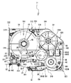
また、第2凹部326の形状も限定されない。例えば、図26に示すように、図13に示すカセットケース31に比べて、カセットケース31の右側面の長さを大きくし、背面の長さを大きくして、第2凹部326の大きさを小さくしてもよい。また、図27に示すように、カセットケース31の右側の側面の後部と背面の右部とが、テープカセット30の内側の中心方向に屈曲することによって、第2凹部326を形成してもよい。また、図28に示すように、カセットケース31の右側面の後部と、背面の右部とを直線で結ぶように第2凹部326を形成してもよい。
Further, the shape of the
また、レセプタタイプのテープカセット30の場合、図29および図30に示すように、印字テープロール571から第2矩形孔692の右側までの印字テープ57の搬送経路の一部に沿うように、第2凹部326の一部を形成してもよい。なお、図29および図30に示すカセットケース31は、サーマルタイプのテープカセット30にも使用することができる。図29および図30に示すカセットケース31は、第2凹部326がテープの搬送経路におけるテープの右上方向への広がりを規制している。これによって、テープの搬送経路を規制する壁と、第2凹部326とを別々に形成する場合と比較して、使用する材料を少なくすることができる。よって、テープカセット30の重量を小さくすることができるとともに、コストダウンをすることができる。
In the case of the receptor
また、カセットケース31の右側面から第2凹部326に至る壁の屈曲の形状、およびカセットケース31の背面から第2凹部326に至る壁の屈曲の形状も限定されない。例えば、カセットケース31の右側面から第2凹部326に向けて屈曲している壁の部分である第1屈曲部326Bを、図29に示すように、略直角に形成してもよい。同様に、カセットケース31の背面から第2凹部326に向けて屈曲している壁の部分である第2屈曲部326Cも、直角に形成してもよい。また、例えば、図30に示すように第1屈曲部326Bと第2屈曲部326Cとを、円弧状に形成してもよい。
Further, the shape of the bent wall extending from the right side surface of the
なお、図26〜図30に示したカセットケース31は、下ケース312のみを記載しているが、上ケース311も第2凹部326の形状に対応するように形成されている。
26 to 30 show only the
上記実施形態において、感熱紙テープ55、印字テープ57、およびフィルムテープ59が、本開示の「テープ」に相当し、感熱紙テープロール551、印字テープロール571、およびフィルムテープロール591が、本開示の「テープロール」に相当する。また、テープ排出部49が、本開示の「排出案内部」に相当し、テープ駆動ローラ46が、本開示の「テープ送りローラ」に相当する。また、ヘッド挿入部39が、本開示の「長孔部」に相当し、内面491,492が、本開示の「内面」に相当する。また、軸孔46Dが、本開示の「ローラ孔」に相当し、ローラ支持孔64が、本開示の「第1開口部」に相当する。また、巻取支持孔68が、本開示の「第2開口部」に相当し、第1テープ支持孔65が、本開示の「第3開口部」に相当する。また、第1矩形孔691が、本開示の「第4開口部」に相当し、第1収納領域30Cが、本開示の「収納領域」に相当する。また、特定領域350が、本開示の「ローラ孔と第3開口部と第4開口部とを互いに結ぶ線によって形成される領域」に相当する。また、第2テープスプール41の周囲に設けられるテープロールが配置される領域が、本開示の「テープ収納領域」に相当し、第1受け部391が、本開示の「第1下側凹部」に相当する。また、残量確認孔70が本開示の「第5開口部」に相当する。
In the above embodiment, the
30 テープカセット
30C 第1収納領域
31 カセットケース
34 アーム部
35 アーム前面壁
39 ヘッド挿入部
44 リボン巻取スプール
46 テープ駆動ローラ
46D 軸孔
49 テープ排出部
50 印字済テープ
55 感熱紙テープ
57 印字テープ
58 両面粘着テープ
59 フィルムテープ
60 インクリボン
64 ローラ支持孔
65 第1テープ支持孔
66 第2テープ支持孔
67 リボン支持孔
68 巻取支持孔
70 残量確認孔
78 テープ露出部
301 上面
302 底面
305 上板
306 底板
311 上ケース
312 下ケース
321 第1角部
322 第2角部
322B 第2下側平面部
323 第3角部
323B 第3下側平面部
325 第1凹部
326 第2凹部
341 排出口
350 特定領域
391 第1受け部
391B 第1下側平面部
491,492 内面
551 感熱紙テープロール
571 印字テープロール
581 両面粘着テープロール
591 フィルムテープロール
601 インクリボンロール
691 第1矩形孔
30 Tape cassette 30C
Claims (15)
上面、底面、および前面と、前記前面に直交する方向である前後方向の一対の側面とを有し、前記上面を形成する上板を有する上ケースと、前記底面を形成する底板を有する下ケースとを含むカセットケースと、
前記カセットケース内に収納され、印字媒体であるテープが巻回されたテープロールと、
前記カセットケースにおいて、前記テープの搬送経路の最下流位置に設けられた角部である第1角部に位置し、前記テープを案内して前記テープカセットから排出する排出案内部と、
前記搬送経路のうち、前記排出案内部の近傍、且つ前記排出案内部に対して前記搬送経路の上流側において、前記テープが前記カセットケースの外部に露出する部分であるテープ露出部と、
前記排出案内部の前記搬送経路の上流側、且つ前記テープ露出部の後側に隣接して設けられた、前記テープを前記排出案内部に搬送するテープ送りローラと、
前記テープへの印字に使用されるインクリボンが巻回されたインクリボンロールと、
前記第1角部に含まれる一の前記側面における前記排出案内部の近傍に形成され、前記側面が前記上板から前記底板に亘って前記カセットケースの内側方向に凹んだ第1凹部と、
前記カセットケースにおいて、前記第1角部の対角上に位置し、他の前記側面の後部が、前記上板から前記底板に亘って前記カセットケースの内側方向に凹んだ第2凹部と
を備え、
前記カセットケースの左右方向の距離は、前記前後方向の距離よりも長く、
前記第1凹部と前記第2凹部との距離は、前記テープカセットの左右方向の距離より短く、
前記テープロールにおける前記テープの巻回中心は、前記第1角部と前記第2凹部とを結ぶ線を基準として前記カセットケースが分けられる2つの領域のうちの1つの領域である第1収納領域に配置され、
前記インクリボンロールにおける前記インクリボンの巻回中心と、前記テープへの印字に使用された前記インクリボンを巻き取るリボン巻取りスプールにおける前記インクリボンの巻回中心とは前記カセットケースが分けられる2つの領域のうちの他の領域である第2収納領域に配置されていることを特徴とするテープカセット。 A tape cassette,
Under having a top surface, a bottom surface and a front surface, and a side surface of a pair of front-rear direction which is a direction orthogonal to the front, and an upper case having a top plate which forms the top surface, a bottom plate forming the bottom surface A cassette case including a case,
Tape rolls housed in the cassette case and wound with a tape as a printing medium;
In the cassette case, a discharge guide portion that is located at a first corner portion that is a corner portion provided at the most downstream position of the tape transport path, guides the tape and discharges it from the tape cassette,
A tape exposure part, which is a part where the tape is exposed to the outside of the cassette case, in the vicinity of the discharge guide part in the transport path and on the upstream side of the transport path with respect to the discharge guide part;
A tape feed roller that conveys the tape to the discharge guide unit, provided upstream of the conveyance path of the discharge guide unit and adjacent to the rear side of the tape exposure unit;
An ink ribbon roll around which an ink ribbon used for printing on the tape is wound;
A first recess formed in the vicinity of the discharge guide portion on one of the side surfaces included in the first corner portion, the side surface being recessed inward of the cassette case from the top plate to the bottom plate;
In the cassette case, a second recessed portion that is located diagonally to the first corner portion, and a rear portion of the other side surface is recessed from the upper plate to the bottom plate inward of the cassette case.
With
The distance in the left-right direction of the cassette case is longer than the distance in the front-rear direction,
The distance between the first recess and the second recess is shorter than the distance in the left-right direction of the tape cassette,
The winding center of the tape in the tape roll is a first storage area that is one of the two areas into which the cassette case is divided with reference to a line connecting the first corner and the second recess. Placed in
The cassette case is divided into the winding center of the ink ribbon in the ink ribbon roll and the winding center of the ink ribbon in the ribbon take-up spool that winds up the ink ribbon used for printing on the tape. A tape cassette arranged in a second storage area, which is another area of the two areas .
前記アーム部の後方に隣接して前記カセットケースの左右方向に延びる、前記カセットケースを上下方向に貫通する長孔部と
を備えたことを特徴とする請求項1に記載のテープカセット。 An arm portion that includes a part of the front surface and guides the tape toward a discharge port along a portion of the transport path that extends in parallel with the front surface;
2. The tape cassette according to claim 1, further comprising an elongated hole portion that extends in the left-right direction of the cassette case adjacent to the rear of the arm portion and penetrates the cassette case in the up-down direction.
前記テープの両面に対向し、前記テープの面に直交する方向への前記テープの移動を制限する一対の内面を備えたことを特徴とする請求項1または2に記載のテープカセット。 The discharge guide part
The tape cassette according to claim 1, further comprising a pair of inner surfaces that face both surfaces of the tape and restrict movement of the tape in a direction orthogonal to the surface of the tape.
上面、底面、および前面と、前記前面に直交する方向である前後方向の一対の側面とを有し、前記上面を形成する上板を有する上ケースと、前記底面を形成する底板を有する下ケースとを含むカセットケースと、 An upper case having an upper surface, a bottom surface, and a front surface, and a pair of side surfaces in a front-rear direction that is perpendicular to the front surface, and having an upper plate that forms the upper surface, and a lower case that has a bottom plate that forms the bottom surface A cassette case including
前記カセットケース内に収納され、印字媒体であるテープが巻回されたテープロールと、 Tape rolls housed in the cassette case and wound with a tape as a printing medium;
前記カセットケースにおいて、前記テープの搬送経路の最下流位置に設けられた角部である第1角部に位置し、前記テープを案内して前記テープカセットから排出する排出案内部と、 In the cassette case, a discharge guide portion that is located at a first corner portion that is a corner portion provided at the most downstream position of the tape transport path, guides the tape and discharges it from the tape cassette,
前記搬送経路のうち、前記排出案内部の近傍、且つ前記排出案内部に対して前記搬送経路の上流側において、前記テープが前記カセットケースの外部に露出する部分であるテープ露出部と、 A tape exposure part, which is a part where the tape is exposed to the outside of the cassette case, in the vicinity of the discharge guide part in the transport path and on the upstream side of the transport path with respect to the discharge guide part;
前記排出案内部の前記搬送経路の上流側、且つ前記テープ露出部の後側に隣接して設けられた、前記テープを前記排出案内部に搬送するテープ送りローラと、 A tape feed roller that conveys the tape to the discharge guide unit, provided upstream of the conveyance path of the discharge guide unit and adjacent to the rear side of the tape exposure unit;
前記第1角部に含まれる一の前記側面における前記排出案内部の近傍に形成され、前記側面が前記上板から前記底板に亘って前記カセットケースの内側方向に凹んだ第1凹部と、 A first recess formed in the vicinity of the discharge guide portion on one of the side surfaces included in the first corner portion, the side surface being recessed inward of the cassette case from the top plate to the bottom plate;
前記カセットケースにおいて、前記第1角部の対角上に位置し、他の前記側面の後部が、前記上板から前記底板に亘って前記カセットケースの内側方向に凹んだ第2凹部と In the cassette case, a second recessed portion that is located diagonally to the first corner portion, and a rear portion of the other side surface is recessed from the upper plate to the bottom plate inward of the cassette case.
を備え、With
前記カセットケースの左右方向の距離は、前記前後方向の距離よりも長く、 The distance in the left-right direction of the cassette case is longer than the distance in the front-rear direction,
前記テープ送りローラは、上下方向を軸方向として配置された筒状部材であり、前記テープ送りローラを上下方向に貫通した孔であるローラ孔を備え、 The tape feed roller is a cylindrical member arranged with the vertical direction as an axial direction, and includes a roller hole that is a hole penetrating the tape feed roller in the vertical direction.
前記カセットケースは、 The cassette case is
前記上板と前記底板との少なくとも一方に設けられ、前記ローラ孔を臨む第1開口部と、 A first opening provided on at least one of the upper plate and the bottom plate and facing the roller hole;
前記上板と前記底板との少なくとも一方に設けられ、前記テープロールにおける前記テープの巻回中心に設けられた孔を臨む第3開口部と、 A third opening that is provided in at least one of the upper plate and the bottom plate and faces a hole provided at a winding center of the tape in the tape roll;
前記第2凹部の前側に設けられ、前記上板と前記底板との少なくとも一方に設けられた第4開口部と A fourth opening provided on the front side of the second recess and provided in at least one of the top plate and the bottom plate;
を備え、With
前記テープロールにおける前記テープの巻回中心は、前記第1角部と前記第2凹部とを結ぶ線を基準として前記カセットケースが分けられる2つの領域のうちの1つの領域である収納領域に配置され、 The winding center of the tape in the tape roll is disposed in a storage area which is one of two areas into which the cassette case is divided with reference to a line connecting the first corner and the second recess. And
前記テープカセットの重心位置は、前記ローラ孔と前記第3開口部と前記第4開口部とを互いに結ぶ線によって形成される領域の内側に位置していることを特徴とするテープカセット。 The center of gravity of the tape cassette is located inside a region formed by a line connecting the roller hole, the third opening, and the fourth opening to each other.
前記テープへの印字に使用された前記インクリボンを巻き取るリボン巻取りスプールと、
前記上板と前記底板との少なくとも一方に設けられ、前記リボン巻取スプールにおける前記インクリボンの巻回中心に設けられた孔を臨む第2開口部と
をさらに備え、
前記テープロールと前記インクリボンロールと前記リボン巻取りスプールとは、前記カセットケースにおける前記第1角部と前記第2凹部とを結んだ対角線と交差する他の対角線上に配置されたことを特徴とする請求項1から4のいずれかに記載のテープカセット。 An ink ribbon roll around which an ink ribbon used for printing on the tape is wound;
A ribbon take-up spool for taking up the ink ribbon used for printing on the tape;
A second opening that is provided in at least one of the upper plate and the bottom plate and faces a hole provided in the winding center of the ink ribbon in the ribbon take-up spool ;
The tape roll, the ink ribbon roll, and the ribbon take-up spool are arranged on another diagonal line that intersects a diagonal line that connects the first corner and the second recess in the cassette case. The tape cassette according to any one of claims 1 to 4 .
上面、底面、および前面と、前記前面に直交する方向である前後方向の一対の側面とを有し、前記上面を形成する上板を有する上ケースと、前記底面を形成する底板を有する下ケースとを含むカセットケースと、
前記カセットケース内に収納され、印字媒体であるテープが巻回されたテープロールと、
前記カセットケースにおいて、前記テープの搬送経路の最下流位置に設けられた角部である第1角部に位置し、前記テープを案内して前記テープカセットから排出する排出案内部と、
前記搬送経路のうち、前記排出案内部の近傍、且つ前記排出案内部に対して前記搬送経路の上流側において、前記テープが前記カセットケースの外部に露出する部分であるテープ露出部と、
前記排出案内部の前記搬送経路の上流側、且つ前記テープ露出部の後側に隣接して設けられた、前記テープを前記排出案内部に搬送するテープ送りローラと、
前記テープへの印字に使用されるインクリボンが巻回されたインクリボンロールと、
印字後の前記テープに貼り合わせられる両面粘着テープが巻回された両面粘着テープロールと、
前記第1角部に含まれる一の前記側面における前記排出案内部の近傍に形成され、前記側面が前記上板から前記底板に亘って前記カセットケースの内側方向に凹んだ第1凹部と、
前記カセットケースにおいて、前記第1角部の対角上に位置し、他の前記側面の後部が、前記上板から前記底板に亘って前記カセットケースの内側方向に凹んだ第2凹部と
を備え、
前記カセットケースの左右方向の距離は、前記前後方向の距離よりも長く、
前記第1凹部と前記第2凹部との距離は、前記テープカセットの左右方向の距離より短く、
前記両面粘着テープロールにおける前記両面粘着テープの巻回中心は、前記第1角部と前記第2凹部とを結ぶ線を基準として前記カセットケースが分けられる2つの領域のうちの1つの領域である第1収納領域に配置され、
前記インクリボンロールにおける前記インクリボンの巻回中心と、前記テープへの印字に使用された前記インクリボンを巻き取るリボン巻取りスプールにおける前記インクリボンの巻回中心とは前記カセットケースが分けられる2つの領域のうちの他の領域である第2収納領域に配置されていることを特徴とするテープカセット。 A tape cassette,
An upper case having an upper surface, a bottom surface, and a front surface, and a pair of side surfaces in a front-rear direction that is perpendicular to the front surface, and having an upper plate that forms the upper surface, and a lower case that has a bottom plate that forms the bottom surface A cassette case including
Tape rolls housed in the cassette case and wound with a tape as a printing medium;
In the cassette case, a discharge guide portion that is located at a first corner portion that is a corner portion provided at the most downstream position of the tape transport path, guides the tape and discharges it from the tape cassette,
A tape exposure part, which is a part where the tape is exposed to the outside of the cassette case, in the vicinity of the discharge guide part in the transport path and on the upstream side of the transport path with respect to the discharge guide part;
A tape feed roller that conveys the tape to the discharge guide unit, provided upstream of the conveyance path of the discharge guide unit and adjacent to the rear side of the tape exposure unit;
An ink ribbon roll around which an ink ribbon used for printing on the tape is wound;
A double-sided pressure-sensitive adhesive tape roll wound with a double-sided pressure-sensitive adhesive tape to be bonded to the tape after printing;
A first recess formed in the vicinity of the discharge guide portion on one of the side surfaces included in the first corner portion, the side surface being recessed inward of the cassette case from the top plate to the bottom plate;
In the cassette case, a second recessed portion that is located diagonally to the first corner portion, and a rear portion of the other side surface is recessed from the upper plate to the bottom plate inward of the cassette case.
With
The distance in the left-right direction of the cassette case is longer than the distance in the front-rear direction,
The distance between the first recess and the second recess is shorter than the distance in the left-right direction of the tape cassette,
The winding center of the double-sided pressure-sensitive adhesive tape in the double-sided pressure-sensitive adhesive tape roll is one of two regions into which the cassette case is divided with reference to a line connecting the first corner and the second recess. Arranged in the first storage area,
The cassette case is divided into the winding center of the ink ribbon in the ink ribbon roll and the winding center of the ink ribbon in the ribbon take-up spool that winds up the ink ribbon used for printing on the tape. A tape cassette arranged in a second storage area, which is another area of the two areas .
前記アーム部の後方に隣接して前記カセットケースの左右方向に延びる、前記カセットケースを上下方向に貫通する長孔部と An elongated hole portion that extends in the left-right direction of the cassette case adjacent to the rear of the arm portion and penetrates the cassette case in the vertical direction;
を備えたことを特徴とする請求項7に記載のテープカセット。The tape cassette according to claim 7, further comprising:
前記テープの両面に対向し、前記テープの面に直交する方向への前記テープの移動を制限する一対の内面を備えたことを特徴とする請求項7または8に記載のテープカセット。 The tape cassette according to claim 7 or 8, further comprising a pair of inner surfaces that face both surfaces of the tape and limit movement of the tape in a direction perpendicular to the surface of the tape.
上面、底面、および前面と、前記前面に直交する方向である前後方向の一対の側面とを有し、前記上面を形成する上板を有する上ケースと、前記底面を形成する底板を有する下ケースとを含むカセットケースと、 An upper case having an upper surface, a bottom surface, and a front surface, and a pair of side surfaces in a front-rear direction that is perpendicular to the front surface, and having an upper plate that forms the upper surface, and a lower case that has a bottom plate that forms the bottom surface A cassette case including
前記カセットケース内に収納され、印字媒体であるテープが巻回されたテープロールと、 Tape rolls housed in the cassette case and wound with a tape as a printing medium;
前記カセットケースにおいて、前記テープの搬送経路の最下流位置に設けられた角部である第1角部に位置し、前記テープを案内して前記テープカセットから排出する排出案内部と、 In the cassette case, a discharge guide portion that is located at a first corner portion that is a corner portion provided at the most downstream position of the tape transport path, guides the tape and discharges it from the tape cassette,
前記搬送経路のうち、前記排出案内部の近傍、且つ前記排出案内部に対して前記搬送経路の上流側において、前記テープが前記カセットケースの外部に露出する部分であるテープ露出部と、 A tape exposure part, which is a part where the tape is exposed to the outside of the cassette case, in the vicinity of the discharge guide part in the transport path and on the upstream side of the transport path with respect to the discharge guide part;
前記排出案内部の前記搬送経路の上流側、且つ前記テープ露出部の後側に隣接して設けられた、前記テープを前記排出案内部に搬送するテープ送りローラと、 A tape feed roller that conveys the tape to the discharge guide unit, provided upstream of the conveyance path of the discharge guide unit and adjacent to the rear side of the tape exposure unit;
前記第1角部に含まれる一の前記側面における前記排出案内部の近傍に形成され、前記側面が前記上板から前記底板に亘って前記カセットケースの内側方向に凹んだ第1凹部と、 A first recess formed in the vicinity of the discharge guide portion on one of the side surfaces included in the first corner portion, the side surface being recessed inward of the cassette case from the top plate to the bottom plate;
前記カセットケースにおいて、前記第1角部の対角上に位置し、他の前記側面の後部が、前記上板から前記底板に亘って前記カセットケースの内側方向に凹んだ第2凹部と、 In the cassette case, a second recess that is located diagonally to the first corner and the rear of the other side surface is recessed from the top plate to the bottom plate inward of the cassette case;
印字後の前記テープに貼り合わせられる両面粘着テープが巻回された両面粘着テープロールと、 A double-sided pressure-sensitive adhesive tape roll wound with a double-sided pressure-sensitive adhesive tape to be bonded to the tape after printing;
前記テープへの印字に使用されるインクリボンが巻回されたインクリボンロールと、 An ink ribbon roll around which an ink ribbon used for printing on the tape is wound;
前記テープへの印字に使用された前記インクリボンを巻き取るリボン巻取りスプールと、 A ribbon take-up spool for taking up the ink ribbon used for printing on the tape;
前記上板と前記底板との少なくとも一方に設けられ、前記リボン巻取スプールにおける前記インクリボンの巻回中心に設けられた孔を臨む第2開口部と、 A second opening provided on at least one of the upper plate and the bottom plate and facing a hole provided at a winding center of the ink ribbon in the ribbon take-up spool;
前記上板と前記底板との少なくとも一方に設けられ、前記両面粘着テープロールにおける前記両面粘着テープの巻回中心に設けられた孔を臨む第3開口部と、 A third opening that is provided on at least one of the upper plate and the bottom plate and faces a hole provided at a winding center of the double-sided pressure-sensitive adhesive tape in the double-sided pressure-sensitive adhesive tape roll;
前記第2凹部の前側に設けられ、前記上板と前記底板との少なくとも一方に設けられた第4開口部と A fourth opening provided on the front side of the second recess and provided in at least one of the top plate and the bottom plate;
を備え、With
前記カセットケースの左右方向の距離は、前記前後方向の距離よりも長く、 The distance in the left-right direction of the cassette case is longer than the distance in the front-rear direction,
前記テープ送りローラは、上下方向を軸方向として配置された筒状部材であり、前記テープ送りローラを上下方向に貫通した孔であるローラ孔を備え、 The tape feed roller is a cylindrical member arranged with the vertical direction as an axial direction, and includes a roller hole that is a hole penetrating the tape feed roller in the vertical direction.
前記カセットケースは、前記上板と前記底板との少なくとも一方に設けられ、前記ローラ孔を臨む第1開口部を備え、 The cassette case is provided on at least one of the upper plate and the bottom plate, and includes a first opening facing the roller hole,
前記両面粘着テープロールと前記インクリボンロールと前記リボン巻取りスプールとは、前記カセットケースにおける前記第1角部と前記第2凹部とを結んだ対角線と交差する他の対角線上に配置され、 The double-sided adhesive tape roll, the ink ribbon roll, and the ribbon take-up spool are disposed on another diagonal line that intersects with a diagonal line that connects the first corner part and the second recess part in the cassette case,
前記テープカセットの重心位置は、前記ローラ孔と前記第3開口部と前記第4開口部とを互いに結ぶ線によって形成される領域の内側に位置していることを特徴とするテープカセット。 The center of gravity of the tape cassette is located inside a region formed by a line connecting the roller hole, the third opening, and the fourth opening to each other.
前記テープへの印字に使用された前記インクリボンを巻き取るリボン巻取りスプールと、
前記上板と前記底板との少なくとも一方に設けられ、前記リボン巻取スプールにおける前記インクリボンの巻回中心に設けられた孔を臨む第2開口部と、
印字後の前記テープに貼り合わせられる両面粘着テープが巻回された両面粘着テープロールと
をさらに備え、
前記両面粘着テープロールと前記インクリボンロールと前記リボン巻取りスプールとは、前記カセットケースにおける前記第1角部と前記第2凹部とを結んだ対角線と交差する他の対角線上に配置されたことを特徴とする請求項7から10のいずれかに記載のテープカセット。 An ink ribbon roll around which an ink ribbon used for printing on the tape is wound;
A ribbon take-up spool for taking up the ink ribbon used for printing on the tape;
A second opening provided on at least one of the upper plate and the bottom plate and facing a hole provided at a winding center of the ink ribbon in the ribbon take-up spool;
Further comprising a <br/> sided adhesive tape roll double-sided adhesive tape is wound to be bonded to said tape after printing,
The double-sided adhesive tape roll, the ink ribbon roll, and the ribbon take-up spool are disposed on another diagonal line that intersects with a diagonal line connecting the first corner and the second recess in the cassette case. The tape cassette according to any one of claims 7 to 10, wherein:
を備えたことを特徴とする請求項2又は8に記載のテープカセット。 In the lower case, a concave portion that is provided to be connected to an end portion of the arm portion on the upstream side in the transport direction of the tape and has a part of the bottom surface that is recessed upward, and is located above the bottom surface. The tape cassette according to claim 2 or 8 , further comprising a first lower concave portion having a first lower flat portion which is a flat portion located.
前記下ケースの前記第2角部に対して対角に位置する角部であって、前記底面より上方に位置する平面部である第3下側平面部を有する第3角部と
を備えたことを特徴とする請求項1から13のいずれかに記載のテープカセット。 One corner portion disposed on another diagonal line intersecting with a diagonal line connecting the first corner portion and the second recess portion in the cassette case, and is a flat portion located above the bottom surface. A second corner having two lower planar portions;
A corner portion located diagonally with respect to the second corner portion of the lower case, and a third corner portion having a third lower plane portion that is a plane portion located above the bottom surface. The tape cassette according to any one of claims 1 to 13 , wherein the tape cassette is provided.
Applications Claiming Priority (5)
| Application Number | Priority Date | Filing Date | Title |
|---|---|---|---|
| JP2009086184A JP4862914B2 (en) | 2009-03-31 | 2009-03-31 | Tape cassette |
| JP2009086172A JP5287433B2 (en) | 2009-03-31 | 2009-03-31 | Tape cassette |
| JP2009086201A JP4862915B2 (en) | 2009-03-31 | 2009-03-31 | Tape cassette |
| JP2009086222A JP5104804B2 (en) | 2009-03-31 | 2009-03-31 | Tape printer |
| PCT/JP2009/071568 WO2010113365A1 (en) | 2009-03-31 | 2009-12-25 | Tape cassette |
Publications (2)
| Publication Number | Publication Date |
|---|---|
| JPWO2010113365A1 JPWO2010113365A1 (en) | 2012-10-04 |
| JP5282815B2 true JP5282815B2 (en) | 2013-09-04 |
Family
ID=42320526
Family Applications (1)
| Application Number | Title | Priority Date | Filing Date |
|---|---|---|---|
| JP2011506968A Active JP5282815B2 (en) | 2009-03-31 | 2009-12-25 | Tape cassette |
Country Status (15)
| Country | Link |
|---|---|
| US (9) | US8757907B2 (en) |
| EP (10) | EP2415612B1 (en) |
| JP (1) | JP5282815B2 (en) |
| KR (2) | KR101719082B1 (en) |
| CN (11) | CN104442030B (en) |
| AU (3) | AU2010231425C1 (en) |
| BR (1) | BRPI1016201B1 (en) |
| CA (2) | CA2936621C (en) |
| DE (2) | DE202010018092U1 (en) |
| MY (1) | MY163211A (en) |
| NZ (2) | NZ617280A (en) |
| PH (2) | PH12014500140B1 (en) |
| RU (1) | RU2523234C2 (en) |
| SG (1) | SG174468A1 (en) |
| WO (3) | WO2010113365A1 (en) |
Families Citing this family (41)
| Publication number | Priority date | Publication date | Assignee | Title |
|---|---|---|---|---|
| PL2202080T3 (en) | 2008-12-25 | 2012-07-31 | Brother Ind Ltd | Tape printer |
| HUE026714T2 (en) | 2008-12-25 | 2016-07-28 | Brother Ind Ltd | Tape cassette and tape printer |
| CN104442030B (en) * | 2009-03-31 | 2017-04-12 | 兄弟工业株式会社 | Tape cassette |
| CN101850665B (en) | 2009-03-31 | 2015-01-14 | 兄弟工业株式会社 | Tape cassette |
| JP5445582B2 (en) | 2009-03-31 | 2014-03-19 | ブラザー工業株式会社 | Tape cassette |
| CN101850662B (en) | 2009-03-31 | 2015-02-11 | 兄弟工业株式会社 | Tape printer |
| JP5136503B2 (en) | 2009-03-31 | 2013-02-06 | ブラザー工業株式会社 | Tape cassette |
| US8641304B2 (en) | 2009-06-30 | 2014-02-04 | Brother Kogyo Kabushiki Kaisha | Tape cassette |
| EP2845743B1 (en) | 2009-12-16 | 2018-01-31 | Brother Kogyo Kabushiki Kaisha | Tape cassette |
| CN102481794B (en) | 2009-12-28 | 2014-12-10 | 兄弟工业株式会社 | Tape cassette |
| WO2013164862A1 (en) * | 2012-05-04 | 2013-11-07 | Kosme S.R.L. Unipersonale | Device for feeding self-adhesive or "pressure sensitive" labels to a labelling machine |
| US9550381B2 (en) * | 2013-04-15 | 2017-01-24 | Brother Kogyo Kabushiki Kaisha | Tape cassette |
| CN103273748B (en) * | 2013-06-07 | 2015-09-30 | 红石电脑(上海)有限公司 | Color ribbon cartridge |
| US9315049B2 (en) * | 2013-12-27 | 2016-04-19 | Brother Kogyo Kabushiki Kaisha | Feed device and printer |
| JP6218657B2 (en) | 2014-03-24 | 2017-10-25 | セイコーエプソン株式会社 | Tape cartridge |
| JP6144221B2 (en) * | 2014-03-24 | 2017-06-07 | セイコーエプソン株式会社 | Tape cartridge |
| CN106132712B (en) * | 2014-03-24 | 2018-01-16 | 精工爱普生株式会社 | Tape printing apparatus and with print system |
| JP6100721B2 (en) | 2014-03-24 | 2017-03-22 | セイコーエプソン株式会社 | Tape cartridge |
| US9821578B2 (en) * | 2014-03-24 | 2017-11-21 | Seiko Epson Corporation | Tape printing apparatus and tape printing system |
| JP6486599B2 (en) * | 2014-03-24 | 2019-03-20 | セイコーエプソン株式会社 | Tape cartridge |
| US9884498B2 (en) | 2014-03-24 | 2018-02-06 | Seiko Epson Corporation | Tape printing device and tape printing system |
| JP6508904B2 (en) * | 2014-09-30 | 2019-05-08 | セイコーエプソン株式会社 | Tape cartridge |
| JP6329096B2 (en) * | 2015-03-19 | 2018-05-23 | セイコーエプソン株式会社 | Tape cartridge |
| JP6365377B2 (en) | 2015-03-31 | 2018-08-01 | ブラザー工業株式会社 | Tape cassette |
| JP6493266B2 (en) * | 2016-03-25 | 2019-04-03 | ブラザー工業株式会社 | Tape cartridge |
| JP6880643B2 (en) * | 2016-10-19 | 2021-06-02 | カシオ計算機株式会社 | Printing equipment |
| JP6790916B2 (en) | 2017-03-01 | 2020-11-25 | セイコーエプソン株式会社 | Tape printing equipment |
| JP6798360B2 (en) | 2017-03-01 | 2020-12-09 | セイコーエプソン株式会社 | Tape printing equipment |
| JP6852473B2 (en) | 2017-03-10 | 2021-03-31 | セイコーエプソン株式会社 | Tape printing equipment |
| US10543703B2 (en) * | 2017-07-31 | 2020-01-28 | Brother Kogyo Kabushiki Kaisha | Tape cassette and tape cassette unit |
| JP6898593B2 (en) * | 2017-10-20 | 2021-07-07 | ブラザー工業株式会社 | Thermal transfer printer |
| JP2019162790A (en) * | 2018-03-20 | 2019-09-26 | ブラザー工業株式会社 | Printer |
| CN111376620B (en) * | 2018-12-26 | 2022-04-29 | 精工爱普生株式会社 | Cartridge to be mounted on tape printer |
| JP7192623B2 (en) * | 2019-03-31 | 2022-12-20 | ブラザー工業株式会社 | cassette |
| JP7439390B2 (en) * | 2019-03-31 | 2024-02-28 | ブラザー工業株式会社 | cassette |
| JP7556677B2 (en) * | 2019-06-26 | 2024-09-26 | セイコーエプソン株式会社 | Tape Printing Device |
| JP7356643B2 (en) * | 2019-06-28 | 2023-10-05 | ブラザー工業株式会社 | tape cassette |
| JP7327059B2 (en) * | 2019-09-30 | 2023-08-16 | ブラザー工業株式会社 | Printer and cassette for printing |
| JP7347077B2 (en) * | 2019-09-30 | 2023-09-20 | ブラザー工業株式会社 | printing cassette |
| CN112009117B (en) * | 2020-09-04 | 2022-02-11 | 珠海趣印科技有限公司 | Ribbon cartridge, label printer and mounting method |
| CN115352691B (en) * | 2022-08-12 | 2023-09-22 | 珠海趣印科技有限公司 | Tape cassette positioning device and paper jam packing system of tape cassette |
Citations (4)
| Publication number | Priority date | Publication date | Assignee | Title |
|---|---|---|---|---|
| JPH07314864A (en) * | 1994-05-25 | 1995-12-05 | Brother Ind Ltd | Tape cassette |
| JPH0839909A (en) * | 1994-07-29 | 1996-02-13 | Brother Ind Ltd | Tape device |
| JPH09188049A (en) * | 1996-01-09 | 1997-07-22 | Brother Ind Ltd | Tape-ribbon complex cassette |
| JP2010234697A (en) * | 2009-03-31 | 2010-10-21 | Brother Ind Ltd | Tape cassette |
Family Cites Families (432)
| Publication number | Priority date | Publication date | Assignee | Title |
|---|---|---|---|---|
| US372044A (en) | 1887-10-25 | John h | ||
| CH121073A (en) | 1925-10-02 | 1927-06-16 | Alsacienne Constr Meca | Device for controlling the ram in Heilmann type combers. |
| CH136498A (en) | 1927-12-24 | 1929-11-15 | Bbc Brown Boveri & Cie | Method and device for preventing reignition in metal vapor rectifiers. |
| US3901372A (en) | 1974-07-22 | 1975-08-26 | Teletype Corp | Protective cover with viewing window for printers |
| JPS52119457A (en) | 1975-10-18 | 1977-10-06 | Sato Tekko Co Ltd | Device for upsetting bar steel or the like |
| NL7606690A (en) | 1976-06-21 | 1977-12-23 | Philips Nv | MAGNET BDNDCASSETTE DEVICE. |
| US4226547A (en) | 1978-07-07 | 1980-10-07 | Kroy Industries Inc. | Printing cartridge |
| JPS5620944U (en) | 1979-07-26 | 1981-02-24 | ||
| US4360278A (en) | 1979-12-17 | 1982-11-23 | Kroy Inc. | Printing apparatus having interchangeable large character type fonts and tape-ribbon cartridge therefor |
| US4278459A (en) | 1980-03-03 | 1981-07-14 | Western Electric Company, Inc. | Method and apparatus for exhausting optical fiber preform tubes |
| US4880325A (en) | 1980-03-17 | 1989-11-14 | Canon Kabushiki Kaisha | Ink ribbon cassette including means for identifying the type of ink ribbon contained therein and containing an ink ribbon having end indication means |
| US4391539A (en) | 1980-05-23 | 1983-07-05 | Kroy Inc. | Tape-ribbon printing cartridge |
| USD267330S (en) | 1980-10-20 | 1982-12-21 | Kroy Industries Inc. | Printing cartridge |
| US4402619A (en) | 1981-03-30 | 1983-09-06 | Kroy, Inc. | Printing apparatus and printing cartridge therefor |
| JPS58139415U (en) | 1982-03-13 | 1983-09-20 | 日本電気精器株式会社 | label printer |
| JPS58220783A (en) | 1982-06-18 | 1983-12-22 | Hitachi Ltd | Ribbon cassette mechanism |
| JPS5978879A (en) | 1982-10-28 | 1984-05-07 | Brother Ind Ltd | Ribbon cassette discriminator for printer |
| SE440897B (en) | 1983-03-15 | 1985-08-26 | Boliden Ab | DISPERSION OF WATER PURIFICATION ENDAMAL CONTAINING IRON (II) + SULPHATE HEATHYDRATE |
| JPS6063782A (en) | 1983-09-19 | 1985-04-12 | Teac Co | Counter of tape traveling device |
| US4678353A (en) | 1983-11-04 | 1987-07-07 | Kroy Inc. | Tape supply cartridge |
| US4557617A (en) | 1983-11-04 | 1985-12-10 | Kroy, Inc. | Tape supply cartridge |
| US4773775A (en) | 1983-11-04 | 1988-09-27 | Kroy Inc. | Tape-ribbon cartridge |
| GB2150915B (en) | 1983-11-07 | 1987-10-28 | Canon Kk | Ink ribbon cassette |
| JPS6099692A (en) | 1983-11-07 | 1985-06-03 | Canon Inc | Ink ribbon cassette supporting device |
| JPS6099692U (en) | 1983-12-14 | 1985-07-06 | 松下電工株式会社 | Airtight structure of the door |
| JPS60130749A (en) | 1983-12-20 | 1985-07-12 | Toray Ind Inc | Film for electrophotography |
| JPS60139465A (en) | 1983-12-28 | 1985-07-24 | Fuji Xerox Co Ltd | Thermal head driving apparatus |
| DE3439089A1 (en) | 1984-10-25 | 1986-05-07 | Olympia Werke Ag, 2940 Wilhelmshaven | RIBBON CASSETTE FOR A WRITING OR SIMILAR OFFICE MACHINE |
| JPS61159657A (en) | 1984-12-31 | 1986-07-19 | Konishiroku Photo Ind Co Ltd | Photosensitive body |
| JPS61179776U (en) | 1985-04-26 | 1986-11-10 | ||
| US4750007A (en) | 1985-08-06 | 1988-06-07 | Canon Kabushiki Kaisha | Ink sheet cassette and image recording apparatus using the same |
| JPH0720725B2 (en) | 1986-03-24 | 1995-03-08 | キヤノン株式会社 | Recording device |
| JPH0761009B2 (en) | 1986-03-12 | 1995-06-28 | 日本電気株式会社 | Frequency synthesizer |
| JPH07108730B2 (en) | 1986-03-28 | 1995-11-22 | 大和製衡株式会社 | Quantitative supply control method |
| JPS62173944U (en) | 1986-04-25 | 1987-11-05 | ||
| JPH0416113Y2 (en) | 1986-05-20 | 1992-04-10 | ||
| USD307918S (en) | 1986-07-21 | 1990-05-15 | General Company Limited | Cassette for a thermicly printing machine or the like |
| US4815871A (en) | 1986-11-14 | 1989-03-28 | Varitronic Systems, Inc. | Head control apparatus |
| JPS6381063U (en) | 1986-11-14 | 1988-05-28 | ||
| USD307296S (en) | 1986-11-17 | 1990-04-17 | Varitronic Systems, Inc. | Printer |
| JPH0630900B2 (en) | 1986-12-27 | 1994-04-27 | キヤノン株式会社 | Output device |
| US4892425A (en) | 1987-01-09 | 1990-01-09 | Hitachi, Ltd. | Thermal transfer recording apparatus and ink sheet cassette therefor |
| JP2607512B2 (en) | 1987-04-13 | 1997-05-07 | 株式会社日立製作所 | Ink paper cassette |
| JPH0437575Y2 (en) | 1987-01-19 | 1992-09-03 | ||
| JPH07108572B2 (en) | 1987-02-19 | 1995-11-22 | セイコーエプソン株式会社 | Printing control device for thermal printer |
| US4844636A (en) | 1987-04-28 | 1989-07-04 | Kroy Inc. | Unitary tape-ribbon cartridge for lettering system |
| JPH079743Y2 (en) | 1987-05-01 | 1995-03-08 | 株式会社クボタ | Side brake operation structure of work vehicle |
| JPS63281572A (en) | 1987-05-14 | 1988-11-18 | Fuji Photo Film Co Ltd | Blanking circuit |
| JPH0674348B2 (en) | 1987-07-09 | 1994-09-21 | 住友化学工業株式会社 | Weather resistant resin composition |
| JP2635049B2 (en) | 1987-07-24 | 1997-07-30 | 株式会社日立製作所 | Thermal transfer recording device |
| JPH01146945A (en) | 1987-12-04 | 1989-06-08 | Nippon Oil & Fats Co Ltd | Vinyl chloride resin composition |
| JPH0730374Y2 (en) | 1988-10-17 | 1995-07-12 | ブラザー工業株式会社 | Shared ribbon cassette |
| US4927278A (en) * | 1987-12-29 | 1990-05-22 | Brother Kogyo Kabushiki Kaisha | Tape cassette and tape printer for use therewith |
| JPH01195088A (en) | 1988-01-30 | 1989-08-04 | Nec Home Electron Ltd | Thermal transfer printer |
| US4930913A (en) | 1988-02-01 | 1990-06-05 | Kroy Inc. | Thermal printing device and tape supply cartridge therefor |
| US4832514A (en) | 1988-02-01 | 1989-05-23 | Kroy Inc. | Thermal transfer device and tape-ribbon cartridge therefor |
| US4815875A (en) | 1988-02-01 | 1989-03-28 | Kroy Inc. | Tape-ribbon cartridge and receiver tray with pivoted cover and cam |
| US5056940A (en) | 1988-02-01 | 1991-10-15 | Kroy Inc. | Thermal printing device and tape supply cartridge therefor |
| US4815874A (en) | 1988-02-01 | 1989-03-28 | Kroy Inc. | Thermal printer and tape-ribbon cartridge with cut-off mechanism |
| USD311416S (en) | 1988-02-01 | 1990-10-16 | Kroy Inc. | Thermal printer tape ribbon cartridge |
| US4917514A (en) | 1988-02-01 | 1990-04-17 | Kroy Inc. | Thermal printing device and tape supply cartridge embodying a tape cut-off mechanism |
| JPH0769497B2 (en) | 1988-02-05 | 1995-07-31 | 日本電信電話株式会社 | Optical component mount |
| CA1338222C (en) | 1988-02-15 | 1996-04-02 | Satoshi Iwata | Method and apparatus for energizing thermal head of a thermal printer |
| JPH0518853Y2 (en) | 1988-02-24 | 1993-05-19 | ||
| USD319070S (en) | 1988-03-04 | 1991-08-13 | Varitronic Systems, Inc. | Cartridge for a printing machine |
| US5078523A (en) | 1988-03-04 | 1992-01-07 | Varitronic Systems, Inc. | Tape cassette with identifying circuit element for printing machine |
| JPH01146945U (en) | 1988-03-31 | 1989-10-11 | ||
| US5227477A (en) | 1988-06-14 | 1993-07-13 | Sandoz Ltd. | Dyes having one or two 2,4- or 4,6-dichloro-5-cyanopyrimidyl groups linked through bridging radicals containing at least two nitrogen atoms to chloro-1,3,5-triazinyl groups |
| US5111216A (en) | 1988-07-12 | 1992-05-05 | Kroy Inc. | Tape supply cartridge for portable thermal printer |
| JPH07101133B2 (en) | 1988-08-31 | 1995-11-01 | 松下電器産業株式会社 | Refrigerant heating warmer / cooler |
| US5188469A (en) | 1988-10-14 | 1993-02-23 | Brother Kogyo Kabushiki Kaisha | Tape feed cassette with tape cutter and guide |
| JPH0434048Y2 (en) * | 1988-10-17 | 1992-08-13 | ||
| JPH0256664U (en) | 1988-10-17 | 1990-04-24 | ||
| US5203951A (en) | 1988-10-19 | 1993-04-20 | Brother Kogyo Kabushiki Kaisha | Tape alignment mechanism |
| JPH0789196B2 (en) | 1988-12-20 | 1995-09-27 | コニカ株式会社 | Camera with film crimping mechanism |
| JPH02147272U (en) | 1989-05-12 | 1990-12-13 | ||
| JPH0649821B2 (en) | 1989-06-13 | 1994-06-29 | 帝人化成株式会社 | Thermoplastic resin composition |
| FR2649510B1 (en) | 1989-07-06 | 1991-12-20 | Collot Richard | METHOD AND SYSTEMS FOR VERIFYING SIGNATURES WITH OPTIMIZATION OF STATIC PARAMETERS |
| USD320391S (en) | 1989-07-17 | 1991-10-01 | Kroy Inc. | Tape supply cartridge |
| US5022771A (en) | 1989-07-17 | 1991-06-11 | Kroy Inc. | Thermal printing apparatus and tape supply cartridge therefor |
| DE4022696A1 (en) | 1989-07-18 | 1991-01-31 | Canon Kk | METHOD AND DEVICE FOR FORMING RECORDS BY MEANS OF A MULTICOLOR RIBBON |
| JPH071782Y2 (en) | 1989-08-16 | 1995-01-18 | 株式会社明電舎 | Hygroscopic breathing apparatus for oil-filled electrical equipment |
| JPH0393584A (en) | 1989-09-06 | 1991-04-18 | Fujitsu Ltd | Ribbon guide mechanism for printer |
| JPH03120680A (en) | 1989-10-03 | 1991-05-22 | Hitachi Maxell Ltd | Tape cartridge |
| US5193919A (en) | 1989-11-09 | 1993-03-16 | Seiko Epson Corporation | Tape printer |
| JP2841573B2 (en) | 1989-11-09 | 1998-12-24 | セイコーエプソン株式会社 | Tape printer |
| US5098208A (en) | 1990-01-12 | 1992-03-24 | Smith Corona Corporation | Ribbon cassette with integral paper guide |
| JP2531075Y2 (en) | 1990-03-19 | 1997-04-02 | 三菱鉛筆株式会社 | Ink ribbon cassette |
| JP2533298Y2 (en) | 1990-03-20 | 1997-04-23 | 日本サーボ株式会社 | Rotating electric machine rotor |
| JPH0621845Y2 (en) | 1990-05-31 | 1994-06-08 | 株式会社寺岡精工 | Cassette printer |
| JPH0437575A (en) | 1990-06-01 | 1992-02-07 | Tokyo Electric Co Ltd | Ribbon shift device of printer |
| JPH0768877B2 (en) | 1990-07-25 | 1995-07-26 | 佐賀野工業株式会社 | Construction method and removal method of earth retaining frame in lateral construction |
| JPH071805Y2 (en) | 1990-09-25 | 1995-01-18 | 東電設計株式会社 | Inner surface shape of LED bulb cover lens |
| JP2969884B2 (en) | 1990-09-26 | 1999-11-02 | ブラザー工業株式会社 | Recording device |
| JPH0720725Y2 (en) | 1990-10-29 | 1995-05-15 | 株式会社クボタ | Indoor pressure control device |
| JPH04168086A (en) | 1990-10-31 | 1992-06-16 | Nec Home Electron Ltd | Color printer |
| GB2250716A (en) | 1990-11-20 | 1992-06-17 | Esselte Dymo Nv | Lid-responsive release of thermal printhead in printer using cassetted ink-ribbon. |
| JP3063155B2 (en) | 1990-11-22 | 2000-07-12 | 富士ゼロックス株式会社 | Control method of image forming apparatus |
| JPH0768814B2 (en) | 1990-12-26 | 1995-07-26 | スワン商事株式会社 | Lower enclosure of door |
| JP2583625Y2 (en) | 1991-08-30 | 1998-10-27 | カシオ計算機株式会社 | Printer |
| JPH0747737Y2 (en) | 1991-02-27 | 1995-11-01 | サンケイ理化株式会社 | Moisture measuring instrument for soil |
| JP3008541B2 (en) | 1991-04-16 | 2000-02-14 | ブラザー工業株式会社 | Printing method |
| US5168284A (en) | 1991-05-01 | 1992-12-01 | Hewlett-Packard Company | Printhead temperature controller that uses nonprinting pulses |
| FR2676223B1 (en) | 1991-05-06 | 1994-11-04 | Inst Francais Du Petrole | PROCESS FOR THE PRODUCTION OF AROMATIC HYDROCARBONS IN A CHAMBER HEATED BY RADIANT VARIABLE THERMAL FLOW HEATING MEANS. |
| USD342275S (en) | 1991-07-22 | 1993-12-14 | Esselte Dymo N.V. | Cassette |
| JP2596263B2 (en) | 1991-07-22 | 1997-04-02 | ブラザー工業株式会社 | Tape cassette manufacturing method and tape cassette |
| US5239437A (en) | 1991-08-12 | 1993-08-24 | Minnesota Mining And Manufacturing Company | Self identifying universal data storage element |
| JPH0516342U (en) | 1991-08-22 | 1993-03-02 | ブラザー工業株式会社 | Tape cartridge device |
| JPH0725123Y2 (en) | 1991-08-26 | 1995-06-07 | 株式会社システムメンテナンス | Artificial nail |
| JPH0563067A (en) | 1991-08-30 | 1993-03-12 | Shin Etsu Handotai Co Ltd | Stacking structure of wafer container |
| JPH0652560A (en) | 1991-09-12 | 1994-02-25 | Nec Corp | Driving device for objective lens |
| JPH0725122Y2 (en) | 1991-10-14 | 1995-06-07 | 一成 奥山 | Haircutting tools |
| JP3031439B2 (en) | 1991-10-21 | 2000-04-10 | ブラザー工業株式会社 | Ribbon cassette and printing device |
| JPH05155067A (en) | 1991-12-06 | 1993-06-22 | Brother Ind Ltd | Image forming apparatus |
| JPH0554225U (en) | 1991-12-26 | 1993-07-20 | カシオ計算機株式会社 | Printer |
| JP2974038B2 (en) | 1991-12-28 | 1999-11-08 | ブラザー工業株式会社 | Barcode recording device |
| JP3448263B2 (en) | 1992-01-08 | 2003-09-22 | ブラザー工業株式会社 | Tape cassette |
| US5350243A (en) | 1992-01-08 | 1994-09-27 | Brother Kogyo Kabushiki Kaisha | Tape cassette |
| JP2583477Y2 (en) | 1992-03-30 | 1998-10-22 | ダイニック株式会社 | Ink ribbon guide of ink ribbon cassette |
| JPH0712008Y2 (en) | 1992-04-06 | 1995-03-22 | アルプス電気株式会社 | Ribbon cassette |
| US5429443A (en) | 1992-04-06 | 1995-07-04 | Alp Electric Co., Ltd. | Thermal transfer printer with ink ribbon feed controller |
| JP2576071Y2 (en) | 1992-07-23 | 1998-07-09 | アルプス電気株式会社 | Ribbon cassette |
| AU115764S (en) | 1992-04-22 | 1992-12-01 | Esselte Dymo Nv | Printer cassette |
| JPH05294051A (en) | 1992-04-23 | 1993-11-09 | Honshu Paper Co Ltd | Ink ribbon cassette |
| JPH05301435A (en) | 1992-04-27 | 1993-11-16 | Honshu Paper Co Ltd | Ink ribbon cassette case |
| JPH0621953U (en) | 1992-08-20 | 1994-03-22 | アルプス電気株式会社 | Mounting structure of ribbon cassette to carriage |
| CA2107746A1 (en) | 1992-10-06 | 1994-04-07 | Masahiko Nunokawa | Tape printing device and tape cartridge used therein |
| JPH06124406A (en) | 1992-10-08 | 1994-05-06 | Sharp Corp | Thin film magnetic head |
| US5595447A (en) | 1992-10-13 | 1997-01-21 | Seiko Epson Corporation | Tape cartridge and printing device having print medium cartridge |
| JP2879636B2 (en) | 1992-10-13 | 1999-04-05 | セイコーエプソン株式会社 | Printing sheet cartridge and printing equipment |
| JP2736950B2 (en) | 1992-10-13 | 1998-04-08 | セイコーエプソン株式会社 | Printing equipment |
| JP2995314B2 (en) | 1992-10-15 | 1999-12-27 | カシオ計算機株式会社 | Tape cassette and printing device |
| FR2696978B1 (en) | 1992-10-19 | 1994-12-09 | Sca Gemplus | Thermal transfer printing process. |
| JP3524111B2 (en) | 1992-11-06 | 2004-05-10 | キヤノン株式会社 | Recording apparatus, facsimile apparatus using the apparatus, and method for detecting jam state thereof |
| US5318370A (en) | 1992-11-17 | 1994-06-07 | Varitronic Systems, Inc. | Cartridge with data memory system and method regarding same |
| JP3287423B2 (en) | 1992-11-25 | 2002-06-04 | ソニー株式会社 | Tape cassette and recording / reproducing device |
| JP3158750B2 (en) | 1992-12-17 | 2001-04-23 | カシオ計算機株式会社 | Printing device |
| JP2939400B2 (en) | 1992-12-25 | 1999-08-25 | アルプス電気株式会社 | Thermal transfer printer and ribbon cassette |
| AU119102S (en) | 1993-01-04 | 1993-12-21 | Dymo Nv | A cassette |
| AU119371S (en) | 1993-01-04 | 1994-02-08 | Dymo Nv | A cassette |
| GB9300716D0 (en) | 1993-01-14 | 1993-03-03 | Esselte Dymo Nv | Printing apparatus with cassette |
| JPH06255145A (en) | 1993-03-02 | 1994-09-13 | Nec Corp | Thermal printer |
| JPH0674348U (en) | 1993-03-30 | 1994-10-21 | 花王株式会社 | Ink ribbon cassette |
| JP3567469B2 (en) | 1993-05-19 | 2004-09-22 | ブラザー工業株式会社 | Tape making device |
| JP3441485B2 (en) | 1993-05-19 | 2003-09-02 | ブラザー工業株式会社 | Tape cassette |
| JP2927146B2 (en) | 1993-06-15 | 1999-07-28 | ブラザー工業株式会社 | Tape cassette |
| JP3426983B2 (en) | 1993-06-25 | 2003-07-14 | ブラザー工業株式会社 | Tape cassette |
| JP2596263Y2 (en) | 1993-06-25 | 1999-06-07 | 株式会社千代田製作所 | Sampling valve device for culture device |
| JPH079743A (en) | 1993-06-28 | 1995-01-13 | Casio Comput Co Ltd | Tape state detection device and tape cassette |
| JPH0768877A (en) | 1993-06-29 | 1995-03-14 | Casio Comput Co Ltd | Housing cassette for tape for printing |
| JP3357128B2 (en) | 1993-06-30 | 2002-12-16 | ブラザー工業株式会社 | Tape making device |
| JP3335433B2 (en) | 1993-07-07 | 2002-10-15 | ブラザー工業株式会社 | Tape cassette |
| GB9314386D0 (en) | 1993-07-12 | 1993-08-25 | Esselte Dymo Nv | A cassette for a thermal printer |
| JPH0725122A (en) | 1993-07-12 | 1995-01-27 | Mitsubishi Pencil Co Ltd | Non-laminated type tape cartridge |
| GB9314387D0 (en) * | 1993-07-12 | 1993-08-25 | Esselte Dymo Nv | Printing apparatus |
| JP3370740B2 (en) | 1993-07-23 | 2003-01-27 | ブラザー工業株式会社 | Tape unit, tape cassette and tape printer |
| JPH0769497A (en) | 1993-09-06 | 1995-03-14 | Mitsubishi Pencil Co Ltd | Tape cartridge for label |
| JPH0768814A (en) * | 1993-09-06 | 1995-03-14 | Brother Ind Ltd | Tape printing device |
| JP3413903B2 (en) | 1993-09-14 | 2003-06-09 | ソニー株式会社 | Recording medium cassette |
| JP3378622B2 (en) | 1993-09-21 | 2003-02-17 | ブラザー工業株式会社 | Tape printer |
| JPH0789115A (en) | 1993-09-24 | 1995-04-04 | Brother Ind Ltd | Thermal printer |
| DE4332608C2 (en) | 1993-09-24 | 2003-01-09 | Meto International Gmbh | cassette |
| JPH07101133A (en) | 1993-09-30 | 1995-04-18 | Brother Ind Ltd | Cassette detection device |
| JP2979495B2 (en) | 1993-10-13 | 1999-11-15 | 株式会社日立製作所 | Ribbon cassette |
| JP3039229B2 (en) | 1993-10-15 | 2000-05-08 | ブラザー工業株式会社 | Thermal printer |
| JP2914128B2 (en) | 1993-11-18 | 1999-06-28 | ブラザー工業株式会社 | Driving device for heating element of thermal head |
| AU122157S (en) | 1993-12-06 | 1994-12-09 | Dymo Nv | A cassette |
| US5411339A (en) | 1993-12-09 | 1995-05-02 | Kroy, Inc. | Portable printer and cartridge therefor |
| JPH0653560U (en) | 1993-12-17 | 1994-07-22 | ブラザー工業株式会社 | Tape cassette |
| JPH07175412A (en) | 1993-12-17 | 1995-07-14 | Brother Ind Ltd | Reflecting printed label and its production |
| US5435657A (en) | 1993-12-28 | 1995-07-25 | Smith Corona Corporation | Label printer and tape and ink ribbon cartridge for use therein |
| JP2584126Y2 (en) | 1993-12-28 | 1998-10-30 | 富士写真フイルム株式会社 | Box case |
| US5399033A (en) | 1994-01-13 | 1995-03-21 | Pelikan, Inc. | Re-inkable ribbon cartridge |
| USD356333S (en) | 1994-02-02 | 1995-03-14 | Smith Corona Corporation | Combined ribbon and tape cartridge |
| JPH07214876A (en) | 1994-02-04 | 1995-08-15 | Brother Ind Ltd | Tape printer |
| JPH07237314A (en) | 1994-02-28 | 1995-09-12 | Nippon Signal Co Ltd:The | High-speed thermal printer |
| JPH07251539A (en) | 1994-03-14 | 1995-10-03 | Brother Ind Ltd | Tape printer |
| JP2882278B2 (en) | 1994-04-08 | 1999-04-12 | 株式会社日立製作所 | Thermal transfer recording device |
| JPH07276695A (en) | 1994-04-08 | 1995-10-24 | Matsushita Electric Ind Co Ltd | Thermal recording apparatus |
| JPH07290803A (en) | 1994-04-25 | 1995-11-07 | Brother Ind Ltd | Ribbon cassette |
| JP3266736B2 (en) | 1994-05-17 | 2002-03-18 | 三菱電機株式会社 | Magnetic sensor |
| US6042280A (en) | 1995-05-25 | 2000-03-28 | Brother Kogyo Kabushiki Kaisha | Tape label printing device |
| JP3212445B2 (en) | 1994-05-25 | 2001-09-25 | ブラザー工業株式会社 | Tape cassette |
| JP2921398B2 (en) | 1994-05-25 | 1999-07-19 | ブラザー工業株式会社 | Tape cassette |
| JP3111445B2 (en) | 1995-03-29 | 2000-11-20 | ブラザー工業株式会社 | Tape-shaped label making device |
| US6196740B1 (en) | 1994-05-25 | 2001-03-06 | Brother Kogyo Kabushiki Kaisha | Tape-shaped label printing device |
| US6190069B1 (en) * | 1994-05-25 | 2001-02-20 | Brother Kogyo Kabushiki Kaisha | Tape-shaped label printing device |
| JPH07314862A (en) | 1994-05-27 | 1995-12-05 | Fuji Photo Film Co Ltd | Ink ribbon cassette |
| US5511891A (en) | 1994-06-14 | 1996-04-30 | Varitronic Systems, Inc. | Tape printing machine with IR sensing |
| JP2943616B2 (en) | 1994-07-14 | 1999-08-30 | ブラザー工業株式会社 | Ribbon cassette |
| JP3266739B2 (en) | 1994-07-15 | 2002-03-18 | ブラザー工業株式会社 | Tape-shaped label making device |
| JP3521494B2 (en) | 1994-08-17 | 2004-04-19 | ブラザー工業株式会社 | Printing cassette |
| JP3275559B2 (en) | 1994-09-20 | 2002-04-15 | 株式会社日立製作所 | Refrigeration equipment |
| JP3009827B2 (en) | 1994-09-22 | 2000-02-14 | シャープ株式会社 | Thermal transfer printer |
| JP3431697B2 (en) | 1994-10-19 | 2003-07-28 | ブラザー工業株式会社 | Printing tape making equipment |
| DE69535836D1 (en) | 1994-11-29 | 2008-10-23 | Seiko Epson Corp | Tape printing device |
| JPH08165035A (en) | 1994-12-12 | 1996-06-25 | Tec Corp | Printer device |
| JP3120680B2 (en) | 1994-12-28 | 2000-12-25 | 日本鋼管株式会社 | Removal method of chloride from sintering machine dust |
| JPH08216461A (en) | 1995-02-13 | 1996-08-27 | Brother Ind Ltd | Printing tape preparing device and cassette therefor |
| JP2976843B2 (en) | 1995-03-29 | 1999-11-10 | ブラザー工業株式会社 | Tape-shaped label making device |
| US5620268A (en) * | 1995-03-29 | 1997-04-15 | Brother Kogyo Kabushiki Kaisha | Composite cassette including a tape cassette and a ribbon cassette |
| CN1085151C (en) | 1995-03-29 | 2002-05-22 | 兄弟工业株式会社 | Combined box containing a paper-tape box and a colour-tape box |
| US5727888A (en) | 1995-03-29 | 1998-03-17 | Brother Kogyo Kabushiki Kaisha | Printer and a composite cassette including a tape cassette and a ribbon cassette used in the printer |
| US6132120A (en) | 1995-03-29 | 2000-10-17 | Brother Kogyo Kabushiki Kaisha | Tape-shaped label printing device |
| JP2998617B2 (en) | 1995-11-01 | 2000-01-11 | ブラザー工業株式会社 | Composite cassette and printer including tape cassette and ribbon cassette |
| JPH08290618A (en) | 1995-04-24 | 1996-11-05 | Brother Ind Ltd | Label forming tape and label forming printer |
| US5659441A (en) | 1995-06-07 | 1997-08-19 | International Business Machines Corporation | Mechanical device enclosure for high performance tape drive |
| US6160679A (en) | 1995-06-30 | 2000-12-12 | Sony Corporation | Recording medium device for use with a tape cartridge having an auxiliary memory viewable through a cartridge discrimination opening |
| GB9513532D0 (en) * | 1995-07-04 | 1995-09-06 | Esselte Dymo Nv | Printing device construction |
| JP3247585B2 (en) | 1995-07-27 | 2002-01-15 | セイコーエプソン株式会社 | Tape cartridge and tape writer |
| JP3353302B2 (en) | 1995-08-10 | 2002-12-03 | セイコーエプソン株式会社 | Inkjet printer cartridge and inkjet printer |
| KR100199778B1 (en) | 1995-08-15 | 1999-06-15 | 가시오 가즈오 | Plate making device with print having a printing function and a cassette which accommodates a recording medium for use with the plate making device |
| GB9517440D0 (en) | 1995-08-25 | 1995-10-25 | Esselte Dymo Nv | Printing apparatus |
| JPH0985928A (en) * | 1995-09-25 | 1997-03-31 | Brother Ind Ltd | Tape cassette |
| JPH09109533A (en) | 1995-10-16 | 1997-04-28 | Brother Ind Ltd | Stamping apparatus |
| JPH09118044A (en) | 1995-10-24 | 1997-05-06 | Brother Ind Ltd | Apparatus for manufacturing tape-shaped label |
| JPH09123579A (en) | 1995-11-02 | 1997-05-13 | Brother Ind Ltd | Stamp tape cassette and stamp device |
| JPH09134557A (en) | 1995-11-07 | 1997-05-20 | Nikon Corp | Optical recording method |
| US5825724A (en) | 1995-11-07 | 1998-10-20 | Nikon Corporation | Magneto-optical recording method using laser beam intensity setting based on playback signal |
| EP0773110B1 (en) | 1995-11-10 | 2002-04-03 | Esselte N.V. | Set of tape cartridges and printing apparatus |
| JPH09141997A (en) | 1995-11-20 | 1997-06-03 | Brother Ind Ltd | Print face forming system for stamp and tape containing cassette for print face of stamp |
| JPH09141986A (en) | 1995-11-22 | 1997-06-03 | Orient Watch Co Ltd | Ribbon guide mechanism and ribbon cassette |
| JP3580332B2 (en) | 1996-01-09 | 2004-10-20 | ブラザー工業株式会社 | Tape and ribbon composite cassette |
| JP2938384B2 (en) | 1996-02-05 | 1999-08-23 | アルプス電気株式会社 | Thermal transfer printer and ribbon cassette used in the thermal transfer printer |
| JP3564848B2 (en) * | 1996-02-16 | 2004-09-15 | ブラザー工業株式会社 | Tape cassette |
| JPH09240158A (en) | 1996-03-12 | 1997-09-16 | Brother Ind Ltd | Tape and tape cassette storing the tape |
| US5823689A (en) | 1996-03-19 | 1998-10-20 | Varitronic Systems, Inc. | Computer system with bi-directional communication and method |
| JPH09300722A (en) * | 1996-05-16 | 1997-11-25 | Brother Ind Ltd | Tape-like label forming apparatus and tape cassette mounted thereon |
| JP3031439U (en) | 1996-05-21 | 1996-11-29 | 塩田 栄子 | Vehicle tampering alarm |
| JPH1056604A (en) | 1996-08-07 | 1998-02-24 | Olympus Optical Co Ltd | Electronic camera with built-in printer and medium to be recorded |
| JP3294777B2 (en) | 1996-12-24 | 2002-06-24 | 東芝テック株式会社 | Print head controller |
| JPH10301701A (en) | 1997-04-30 | 1998-11-13 | Casio Comput Co Ltd | Device for inputting handwritten data and program storing medium for the same |
| JPH1110929A (en) | 1997-06-25 | 1999-01-19 | Sony Corp | Ink ribbon, printer apparatus and printing method |
| GB9808445D0 (en) | 1998-04-21 | 1998-06-17 | Esselte Nv | Tape printing device |
| JP3702604B2 (en) | 1997-09-05 | 2005-10-05 | カシオ計算機株式会社 | Tape cassette |
| JP3814976B2 (en) | 1997-09-08 | 2006-08-30 | カシオ計算機株式会社 | Tape cassette |
| JP3711427B2 (en) | 1997-09-18 | 2005-11-02 | カシオ計算機株式会社 | Tape printer |
| JPH11105351A (en) | 1997-10-02 | 1999-04-20 | Casio Comput Co Ltd | Printing tape and cassette with the same housed therein |
| JPH11129563A (en) | 1997-11-04 | 1999-05-18 | Sony Corp | Ribbon spool structure for ink ribbon cartridge |
| EP0919393B1 (en) | 1997-11-27 | 2004-02-11 | Esselte N.V. | Refillable tape cassette |
| JPH11185441A (en) | 1997-12-24 | 1999-07-09 | Aiwa Co Ltd | Data storage cassette and data recording/reproducing device |
| US6190065B1 (en) | 1998-03-27 | 2001-02-20 | Kroy Llc | Thermal imaging tape cartridge |
| JP3846035B2 (en) | 1998-06-22 | 2006-11-15 | ブラザー工業株式会社 | Tape printer |
| JP4521890B2 (en) | 1998-06-24 | 2010-08-11 | カシオ計算機株式会社 | Printing device |
| US6168328B1 (en) | 1998-07-01 | 2001-01-02 | Alps Electric Co., Ltd. | Thermal transfer printer with a plurality of cassette holder plates |
| JP2000085224A (en) | 1998-07-13 | 2000-03-28 | Alps Electric Co Ltd | Heat-transfer recording device |
| JP2000025251A (en) | 1998-07-10 | 2000-01-25 | Canon Inc | Ink jet recorder |
| JP2000043337A (en) | 1998-07-28 | 2000-02-15 | Brother Ind Ltd | Tape cassette |
| JP3846048B2 (en) | 1998-07-28 | 2006-11-15 | ブラザー工業株式会社 | Tape cassette |
| US6048118A (en) | 1998-08-07 | 2000-04-11 | Axiohm Transaction Solutions, Inc. | Compact ribbon cassette with integral friction plate |
| JP3852216B2 (en) | 1998-08-31 | 2006-11-29 | ブラザー工業株式会社 | Two-dimensional code data conversion recording medium, two-dimensional code data conversion device and printer |
| US6190067B1 (en) * | 1998-09-21 | 2001-02-20 | Casio Computer., Ltd. | Cassette containing magnetically affixable printing tape |
| JP3882360B2 (en) | 1998-09-28 | 2007-02-14 | ブラザー工業株式会社 | Tape cassette |
| JP2000103131A (en) | 1998-09-29 | 2000-04-11 | Brother Ind Ltd | Tape cassette |
| JP4239282B2 (en) | 1998-10-30 | 2009-03-18 | ブラザー工業株式会社 | Stamp making device |
| EP1052105A4 (en) | 1998-11-27 | 2003-05-14 | King Jim Co Ltd | Tape cartridge holding mechanism and tape printer having the same |
| JP3654023B2 (en) | 1999-01-20 | 2005-06-02 | セイコーエプソン株式会社 | Tape printer |
| JP3543659B2 (en) | 1999-01-25 | 2004-07-14 | ブラザー工業株式会社 | Tape cassette |
| JP3543660B2 (en) * | 1999-01-25 | 2004-07-14 | ブラザー工業株式会社 | Tape cassette |
| JP2000229750A (en) | 1999-02-09 | 2000-08-22 | Casio Comput Co Ltd | Paper cassette and recording paper |
| JP2000274872A (en) | 1999-03-19 | 2000-10-06 | Matsushita Refrig Co Ltd | Manifold incorporating thermoelectric module |
| JP3106187B2 (en) | 1999-03-19 | 2000-11-06 | 工業技術院長 | Optical actuator element |
| JP3063155U (en) | 1999-04-16 | 1999-10-19 | 凸版印刷株式会社 | Hanging display labels |
| US6167696B1 (en) | 1999-06-04 | 2001-01-02 | Ford Motor Company | Exhaust gas purification system for low emission vehicle |
| JP2001011594A (en) | 1999-06-29 | 2001-01-16 | Mitsubishi Heavy Ind Ltd | Metal-based compound preform and its manufacture, hot press, and metal-based composite material and its manufacture |
| WO2001010649A1 (en) | 1999-08-06 | 2001-02-15 | Brother Industries, Ltd. | Tape supply cartridge |
| US6476838B1 (en) | 1999-09-03 | 2002-11-05 | Oki Data America, Inc. | Method of driving a thermal print head |
| US6485206B1 (en) | 1999-09-14 | 2002-11-26 | Brother Kogyo Kabushiki Kaisha | Cassette and detecting device for installation thereof |
| JP2001088359A (en) | 1999-09-24 | 2001-04-03 | Brother Ind Ltd | Tape printer |
| JP3335152B2 (en) | 1999-12-17 | 2002-10-15 | セイコーエプソン株式会社 | Ribbon cartridge |
| JP2001319447A (en) | 2000-10-05 | 2001-11-16 | Fuji Photo Film Co Ltd | Magnetic disk cartridge |
| US6419648B1 (en) | 2000-04-21 | 2002-07-16 | Insightec-Txsonics Ltd. | Systems and methods for reducing secondary hot spots in a phased array focused ultrasound system |
| JP2002042441A (en) | 2000-05-19 | 2002-02-08 | Tdk Corp | Tape cartridge |
| US6429443B1 (en) | 2000-06-06 | 2002-08-06 | Applied Materials, Inc. | Multiple beam electron beam lithography system |
| JP2002026108A (en) * | 2000-07-12 | 2002-01-25 | Tokyo Electron Ltd | Transfer mechanism for works, processing system and method of using transfer mechanism |
| JP3928340B2 (en) | 2000-08-04 | 2007-06-13 | セイコーエプソン株式会社 | Tape cartridge and tape printer to which the cartridge is mounted |
| JP2001121797A (en) | 2000-09-06 | 2001-05-08 | Brother Ind Ltd | Tape printer and cassette for printer |
| JP2002103762A (en) | 2000-09-29 | 2002-04-09 | Pfu Ltd | Ribbon cassette |
| JP3971791B2 (en) | 2000-09-29 | 2007-09-05 | 日立マクセル株式会社 | Storage case for tape cartridge |
| CN1274514C (en) | 2000-10-19 | 2006-09-13 | 兄弟工业株式会社 | Tape cassette and tape unit |
| JP2002308481A (en) | 2000-10-19 | 2002-10-23 | Brother Ind Ltd | Tape cassette and tape unit |
| JP2002308518A (en) | 2000-10-19 | 2002-10-23 | Brother Ind Ltd | Tape unit |
| WO2002034540A1 (en) | 2000-10-19 | 2002-05-02 | Brother Kogyo Kabushiki Kaisha | Tape cassette |
| ATE348005T1 (en) | 2000-10-20 | 2007-01-15 | Seiko Epson Corp | INKJET RECORDING APPARATUS AND INK CARTRIDGE |
| JP4420556B2 (en) | 2000-12-01 | 2010-02-24 | セイコーエプソン株式会社 | Tape printer |
| JP4663102B2 (en) | 2000-12-01 | 2011-03-30 | セイコーエプソン株式会社 | Cartridge holding device and tape printer provided with the same |
| JP4456259B2 (en) | 2000-12-01 | 2010-04-28 | セイコーエプソン株式会社 | Cartridge detection apparatus and tape printing apparatus having the same |
| JP2002179300A (en) | 2000-12-15 | 2002-06-26 | Brother Ind Ltd | Tape cassette and tape unit |
| JP4507403B2 (en) | 2000-12-26 | 2010-07-21 | ブラザー工業株式会社 | Tape printer |
| US20020135938A1 (en) | 2001-02-21 | 2002-09-26 | Fuji Photo Film Co., Ltd. | Record medium cartridge and molded resin parts |
| JP3515536B2 (en) | 2001-03-19 | 2004-04-05 | セイコーエプソン株式会社 | Tape writer |
| US7830405B2 (en) | 2005-06-23 | 2010-11-09 | Zink Imaging, Inc. | Print head pulsing techniques for multicolor printers |
| JP2002367333A (en) | 2001-06-12 | 2002-12-20 | Fuji Photo Film Co Ltd | Casing |
| JP3815266B2 (en) | 2001-06-27 | 2006-08-30 | カシオ計算機株式会社 | Printing device |
| JP4017097B2 (en) | 2001-07-16 | 2007-12-05 | 株式会社明治ゴム化成 | Plastic pallet |
| JP2003048337A (en) | 2001-08-06 | 2003-02-18 | Riso Kagaku Corp | Method and apparatus for controlling thermal head |
| JP4631237B2 (en) | 2001-09-05 | 2011-02-16 | ブラザー工業株式会社 | Thermal recording device |
| JP2003128350A (en) | 2001-10-30 | 2003-05-08 | Canon Inc | Sheet conveying device and image forming device |
| USD486853S1 (en) | 2001-11-01 | 2004-02-17 | Brady Worldwide, Inc. | Printer cartridge |
| US6644876B2 (en) | 2001-11-01 | 2003-11-11 | Brady Worldwide, Inc. | Method and apparatus for printer cartridge identification |
| JP2003145902A (en) | 2001-11-13 | 2003-05-21 | Alps Electric Co Ltd | Ribbon cassette and thermal transfer printer using it |
| CN1225314C (en) | 2002-02-01 | 2005-11-02 | 北京科技大学 | Oxygen blowing apparatus for smelting steel, technology and application |
| JP2003251902A (en) | 2002-02-28 | 2003-09-09 | Max Co Ltd | Ink ribbon cassette holding mechanism of thermal transfer printer |
| JP3719223B2 (en) | 2002-03-04 | 2005-11-24 | セイコーエプソン株式会社 | Ribbon cartridge for recording apparatus and recording apparatus |
| JP2003285522A (en) | 2002-03-27 | 2003-10-07 | Brother Ind Ltd | Cassette |
| JP2003285488A (en) * | 2002-03-27 | 2003-10-07 | Brother Ind Ltd | Cassette |
| USD542334S1 (en) | 2002-05-15 | 2007-05-08 | Brother Industries, Ltd. | Tape cartridge for tape printing machine |
| USD534203S1 (en) | 2002-05-15 | 2006-12-26 | Brother Industries, Ltd. | Tape cartridge for tape printing machine |
| JP2004018077A (en) | 2002-06-19 | 2004-01-22 | Dainippon Printing Co Ltd | Paper-made container |
| JP3994804B2 (en) | 2002-06-25 | 2007-10-24 | ブラザー工業株式会社 | Tape printer and tape cassette |
| JP3700692B2 (en) * | 2002-09-27 | 2005-09-28 | ブラザー工業株式会社 | Ribbon cassette |
| JP3882742B2 (en) | 2002-11-08 | 2007-02-21 | ブラザー工業株式会社 | Thermal recording device |
| GB0230199D0 (en) | 2002-12-24 | 2003-02-05 | Esselte Nv | Information on consumables |
| CN101683790B (en) | 2002-12-24 | 2013-01-02 | 迪默公司 | Printing apparatus and cartridge |
| RU2328379C2 (en) * | 2002-12-24 | 2008-07-10 | Даймо | Printer and cassette |
| JP2004226472A (en) | 2003-01-20 | 2004-08-12 | Fuji Photo Film Co Ltd | Lithographic printing original plate |
| JP2004255656A (en) | 2003-02-25 | 2004-09-16 | Seiko Epson Corp | Tape cartridge and tape printer |
| KR100466180B1 (en) | 2003-03-17 | 2005-01-13 | 변영광 | Cosmetic Case of Button Open Type |
| JP3846443B2 (en) | 2003-03-28 | 2006-11-15 | ブラザー工業株式会社 | Tape printer |
| JP2004345179A (en) | 2003-05-21 | 2004-12-09 | Fuji Photo Film Co Ltd | Thermal printer and its cooling fan controlling method |
| JP2005014524A (en) | 2003-06-27 | 2005-01-20 | King Jim Co Ltd | Printer, method of printing and program |
| US20070098473A1 (en) | 2003-06-27 | 2007-05-03 | Geert Heyse | Tape printing apparatus and tape cassette |
| US7070347B2 (en) | 2003-08-12 | 2006-07-04 | Brady Worldwide, Inc. | Printer with a pivoting gear mechanism |
| US6910819B2 (en) | 2003-08-12 | 2005-06-28 | Brady Worldwide, Inc. | Printer cartridge |
| US6929415B2 (en) | 2003-08-12 | 2005-08-16 | Brady Worldwide, Inc. | Wire marker label media |
| JP4211534B2 (en) | 2003-08-19 | 2009-01-21 | セイコーエプソン株式会社 | Printing control method and printing apparatus for recording medium for retransfer |
| WO2005045824A1 (en) | 2003-11-11 | 2005-05-19 | Hitachi Maxell, Ltd. | Tape drive |
| JP4133756B2 (en) | 2003-11-14 | 2008-08-13 | Nec液晶テクノロジー株式会社 | Connection method of printed wiring board |
| JP4434718B2 (en) | 2003-12-19 | 2010-03-17 | 株式会社東芝 | Transfer apparatus and transfer method |
| JP4333367B2 (en) | 2004-01-06 | 2009-09-16 | ブラザー工業株式会社 | Roll sheet holder and tape printer |
| DE102004002929A1 (en) | 2004-01-14 | 2005-08-04 | Laser- Und Medizin- Technologie Gmbh | Method for determining color perception in multilayer systems |
| JP2005231203A (en) | 2004-02-19 | 2005-09-02 | Seiko Epson Corp | Cartridge mounter and tape printer with cartridge mounter |
| GB2412351A (en) | 2004-03-24 | 2005-09-28 | Esselte | A tape printer having separate tape and ink ribbon cassettes |
| JP4379177B2 (en) | 2004-03-29 | 2009-12-09 | ブラザー工業株式会社 | Tape cassette |
| USD519522S1 (en) | 2004-04-09 | 2006-04-25 | Cowon Systems, Inc. | Digital audio player |
| WO2005101306A1 (en) | 2004-04-12 | 2005-10-27 | Brother Kogyo Kabushiki Kaisha | Radio tag circuit element cartridge, roll for electro-magnetic wave reactor label forming device, and tag label forming device |
| JP4784045B2 (en) | 2004-04-12 | 2011-09-28 | ブラザー工業株式会社 | Tag label producing device cartridge and tag label producing device |
| JP2005298031A (en) | 2004-04-14 | 2005-10-27 | Sekisui Chem Co Ltd | Packaging material for eaves gutter |
| JP3901171B2 (en) | 2004-05-24 | 2007-04-04 | ブラザー工業株式会社 | Tape cassette and tape printer |
| WO2005120844A1 (en) | 2004-06-14 | 2005-12-22 | Citizen Watch Co., Ltd. | Ribbon feeder and printer |
| JP3106187U (en) | 2004-06-25 | 2004-12-16 | 船井電機株式会社 | Television cabinet and television receiver |
| JP4001132B2 (en) | 2004-07-08 | 2007-10-31 | セイコーエプソン株式会社 | Tape printer |
| AU2005268499B2 (en) | 2004-07-30 | 2012-01-19 | Dymo | Cassette locking and ejecting arrangement |
| JP2006053967A (en) | 2004-08-10 | 2006-02-23 | Hitachi Maxell Ltd | Magnetic tape cartridge |
| GB0417795D0 (en) | 2004-08-10 | 2004-09-15 | Esselte Nv | Cassette locking and ejecting arrangement |
| JP4648128B2 (en) | 2004-09-02 | 2011-03-09 | カシオ計算機株式会社 | Tape cassette |
| WO2006033431A1 (en) | 2004-09-24 | 2006-03-30 | Brother Kogyo Kabushiki Kaisha | Tape printing device and tape cassette |
| CN101060985B (en) | 2004-09-24 | 2012-06-13 | 兄弟工业株式会社 | Tape cassette and tape printer |
| WO2006033389A1 (en) | 2004-09-24 | 2006-03-30 | Brother Kogyo Kabushiki Kaisha | Tape printer |
| EP1800874A4 (en) | 2004-09-24 | 2010-01-13 | Brother Ind Ltd | Tape cassette and tape printing device |
| JP4576964B2 (en) | 2004-09-28 | 2010-11-10 | ブラザー工業株式会社 | Label producing apparatus, program, and recording medium |
| GB0423010D0 (en) | 2004-10-15 | 2004-11-17 | Esselte | Cassette |
| JP2006116823A (en) | 2004-10-21 | 2006-05-11 | Seiko Epson Corp | Tape cartridge and tape processor which enables its detachable mount |
| JP2005088597A (en) | 2004-11-15 | 2005-04-07 | Brother Ind Ltd | Tape cassette |
| JP2006168974A (en) | 2004-12-20 | 2006-06-29 | Seiko Epson Corp | Roll paper holding shaft, roll paper holding device, printer and processing device equipped with the printer |
| JP4617874B2 (en) | 2004-12-27 | 2011-01-26 | ブラザー工業株式会社 | Tape printer |
| WO2006070790A1 (en) * | 2004-12-27 | 2006-07-06 | Brother Kogyo Kabushiki Kaisha | Label producing device, device for detecting mark and tape end, tape roll and cartridge for label, and tape with mark |
| JP4617873B2 (en) | 2004-12-27 | 2011-01-26 | ブラザー工業株式会社 | Tape printer |
| JP2006213010A (en) * | 2005-02-07 | 2006-08-17 | Brother Ind Ltd | Tape cassette |
| DE102005007220B4 (en) | 2005-02-15 | 2007-08-16 | Francotyp-Postalia Gmbh | Method and arrangement for controlling the printing of a thermal transfer printing device |
| JP4736457B2 (en) | 2005-02-17 | 2011-07-27 | ブラザー工業株式会社 | Tape cassette |
| JP4561830B2 (en) | 2005-02-24 | 2010-10-13 | セイコーエプソン株式会社 | Ribbon cartridge and recording apparatus |
| JP4380560B2 (en) | 2005-02-25 | 2009-12-09 | セイコーエプソン株式会社 | Braille marking device control method, braille marking device and program |
| JP4529732B2 (en) | 2005-03-01 | 2010-08-25 | ブラザー工業株式会社 | Tape printer |
| JP2006248059A (en) | 2005-03-11 | 2006-09-21 | Brother Ind Ltd | Tape printer, tape printing program, and tape cassette |
| MX2007011310A (en) | 2005-03-16 | 2007-10-08 | Panduit Corp | Hand-held thermal transfer printer for labeling. |
| JP4561442B2 (en) * | 2005-03-30 | 2010-10-13 | ブラザー工業株式会社 | Tape cassette |
| JP4274144B2 (en) | 2005-04-25 | 2009-06-03 | 船井電機株式会社 | Ink sheet cartridge |
| JP4061507B2 (en) | 2005-07-07 | 2008-03-19 | ブラザー工業株式会社 | cassette |
| US7330201B2 (en) | 2005-09-28 | 2008-02-12 | Eastman Kodak Company | Thermal printer and method for operating same |
| JP5017840B2 (en) | 2005-10-18 | 2012-09-05 | ブラザー工業株式会社 | Tape printer |
| JP4539593B2 (en) | 2005-11-28 | 2010-09-08 | ブラザー工業株式会社 | Ink cartridge, ink jet recording apparatus, ink jet recording system |
| JP4289349B2 (en) | 2005-12-21 | 2009-07-01 | ブラザー工業株式会社 | Tape printer |
| JP4692275B2 (en) | 2005-12-28 | 2011-06-01 | ブラザー工業株式会社 | Cassette for printing |
| JP3120680U (en) | 2005-12-30 | 2006-04-20 | 充章 中野 | Multi-room pan |
| JP2007230155A (en) | 2006-03-02 | 2007-09-13 | Sony Corp | Ink ribbon cartridge and printer device |
| JP4904882B2 (en) | 2006-03-29 | 2012-03-28 | ブラザー工業株式会社 | Printing cassette and lettering tape |
| JP2007268815A (en) | 2006-03-30 | 2007-10-18 | Sony Corp | Printer device |
| EP2018974B1 (en) * | 2006-05-18 | 2011-06-22 | Brother Kogyo Kabushiki Kaisha | Print tape and print-use cassette |
| JP2006240310A (en) | 2006-05-31 | 2006-09-14 | Brother Ind Ltd | Tape-like label generating apparatus and tape cassette |
| JP2006289991A (en) | 2006-06-05 | 2006-10-26 | Brother Ind Ltd | Cassette case |
| JP4059282B2 (en) | 2006-07-18 | 2008-03-12 | ブラザー工業株式会社 | Cassette and tape printer |
| GB2440728A (en) | 2006-07-26 | 2008-02-13 | Dymo B V B A | Printing on multilayered tape |
| GB0614868D0 (en) | 2006-07-26 | 2006-09-06 | Dymo B V B A | Tape printing apparatus and tape cassette |
| JP2008044180A (en) | 2006-08-11 | 2008-02-28 | Canon Inc | Ink cassette, bobbin holding structure, and printer |
| JP2008062474A (en) | 2006-09-06 | 2008-03-21 | Casio Comput Co Ltd | Printer |
| JP2008080668A (en) | 2006-09-28 | 2008-04-10 | Brother Ind Ltd | Print tape, tape cassette and tape printer |
| JP4853203B2 (en) | 2006-09-28 | 2012-01-11 | ブラザー工業株式会社 | Tape cassette |
| JP4702291B2 (en) | 2007-01-22 | 2011-06-15 | ブラザー工業株式会社 | Printing device |
| JP4994864B2 (en) | 2007-01-25 | 2012-08-08 | ニスカ株式会社 | Printer device, attaching / detaching method, printer cartridge, and ink ribbon body |
| JP2008213462A (en) | 2007-02-09 | 2008-09-18 | Brother Ind Ltd | Tape printing device, tape printing program, and tape cassette |
| JP2008221553A (en) | 2007-03-12 | 2008-09-25 | Brother Ind Ltd | Lettering tape and printer |
| JP4998103B2 (en) | 2007-06-12 | 2012-08-15 | ブラザー工業株式会社 | Lettering tape and tape cassette |
| US20080226373A1 (en) | 2007-03-12 | 2008-09-18 | Brother Kogyo Kabushiki Kaishi | Lettering tape, tape cassette, tape printer |
| JP2008221726A (en) | 2007-03-14 | 2008-09-25 | Brother Ind Ltd | Tape cassette and printer |
| JP2008229855A (en) | 2007-03-16 | 2008-10-02 | Hitachi Omron Terminal Solutions Corp | Thermal head control device and thermal head control method |
| JP2008265278A (en) | 2007-03-22 | 2008-11-06 | Brother Ind Ltd | Label tape, label tape cartridge, and label forming device |
| JP5012156B2 (en) | 2007-04-06 | 2012-08-29 | ブラザー工業株式会社 | Tape cassette and printing apparatus |
| JP2008265180A (en) * | 2007-04-23 | 2008-11-06 | Seiko Epson Corp | Tape cartridge and tape printer |
| JP2008279678A (en) | 2007-05-11 | 2008-11-20 | Seiko Epson Corp | Tape printing system, tape cartridge, and tape printing device |
| US8109684B2 (en) | 2007-06-11 | 2012-02-07 | Brother Kogyo Kabushiki Kaisha | Tape printing system with auxiliary cassette containing auxiliary medium for contacting printed tape |
| JP4924267B2 (en) | 2007-07-26 | 2012-04-25 | ブラザー工業株式会社 | Tape printer |
| JP4561789B2 (en) | 2007-08-02 | 2010-10-13 | セイコーエプソン株式会社 | Tape cartridge |
| JP2008094103A (en) | 2007-10-26 | 2008-04-24 | Brother Ind Ltd | Tape for label writer, and tape cassette in which tape is housed |
| USD579942S1 (en) | 2007-12-07 | 2008-11-04 | Dymo | Cassette |
| JP5294051B2 (en) | 2008-03-25 | 2013-09-18 | 株式会社リコー | Zoom lens, imaging device |
| WO2009107534A1 (en) | 2008-02-29 | 2009-09-03 | ブラザー工業株式会社 | Tape cassette, tape making apparatus and tape making system |
| JP2009214431A (en) | 2008-03-11 | 2009-09-24 | Brother Ind Ltd | Tape cassette |
| JP5155067B2 (en) | 2008-08-28 | 2013-02-27 | エルジー ディスプレイ カンパニー リミテッド | Image display device |
| WO2010054182A1 (en) | 2008-11-10 | 2010-05-14 | Brady Worldwide, Inc. | Cartridge media retention mechanism |
| JP5326874B2 (en) | 2009-06-30 | 2013-10-30 | ブラザー工業株式会社 | Tape cassette |
| PL2202080T3 (en) | 2008-12-25 | 2012-07-31 | Brother Ind Ltd | Tape printer |
| HUE026714T2 (en) | 2008-12-25 | 2016-07-28 | Brother Ind Ltd | Tape cassette and tape printer |
| CN101850662B (en) | 2009-03-31 | 2015-02-11 | 兄弟工业株式会社 | Tape printer |
| JP4428462B2 (en) | 2009-03-31 | 2010-03-10 | ブラザー工業株式会社 | Tape cassette and tape printer |
| JP4947085B2 (en) | 2009-03-31 | 2012-06-06 | ブラザー工業株式会社 | Tape cassette |
| JP5445582B2 (en) | 2009-03-31 | 2014-03-19 | ブラザー工業株式会社 | Tape cassette |
| CN104442030B (en) | 2009-03-31 | 2017-04-12 | 兄弟工业株式会社 | Tape cassette |
| JP5233971B2 (en) | 2009-11-27 | 2013-07-10 | ブラザー工業株式会社 | Tape cassette |
| JP5233970B2 (en) | 2009-11-27 | 2013-07-10 | ブラザー工業株式会社 | Ribbon cassette |
| CN101850665B (en) | 2009-03-31 | 2015-01-14 | 兄弟工业株式会社 | Tape cassette |
| JP5229196B2 (en) | 2009-11-27 | 2013-07-03 | ブラザー工業株式会社 | Tape cassette |
| CN102458867B (en) | 2009-04-28 | 2015-04-08 | 迪默公司 | Label printer box |
| JP5343737B2 (en) | 2009-06-30 | 2013-11-13 | ブラザー工業株式会社 | Tape cassette |
| US8641304B2 (en) | 2009-06-30 | 2014-02-04 | Brother Kogyo Kabushiki Kaisha | Tape cassette |
| JP5326950B2 (en) | 2009-09-09 | 2013-10-30 | ブラザー工業株式会社 | Tape cassette |
| JP2011141930A (en) * | 2010-01-07 | 2011-07-21 | Fujifilm Corp | Recording tape cartridge |
| USD681727S1 (en) | 2010-04-28 | 2013-05-07 | Dymo | Cassette |
| US9102180B2 (en) | 2010-07-29 | 2015-08-11 | Brady Worldwide, Inc. | Cartridge assembly with ribbon lock |
| US8734035B2 (en) | 2010-07-29 | 2014-05-27 | Brady Worldwide, Inc. | Media cartridge with shifting ribs |
| US9108449B2 (en) | 2010-07-29 | 2015-08-18 | Brady Worldwide, Inc. | Cartridge assembly with edge protector |
| CN202895934U (en) | 2012-11-02 | 2013-04-24 | 江西镭博钛电子科技有限公司 | Band box capable of being detachably installed in band printer |
-
2009
- 2009-12-25 CN CN201410723249.5A patent/CN104442030B/en active Active
- 2009-12-25 CN CN200980158165.9A patent/CN102361760B/en active Active
- 2009-12-25 EP EP09842716.4A patent/EP2415612B1/en active Active
- 2009-12-25 JP JP2011506968A patent/JP5282815B2/en active Active
- 2009-12-25 WO PCT/JP2009/071568 patent/WO2010113365A1/en active Application Filing
-
2010
- 2010-03-26 DE DE201020018092 patent/DE202010018092U1/en not_active Expired - Lifetime
- 2010-03-26 EP EP12161271.7A patent/EP2471668B1/en active Active
- 2010-03-26 RU RU2011143791/12A patent/RU2523234C2/en active
- 2010-03-26 EP EP23214885.8A patent/EP4309904A3/en active Pending
- 2010-03-26 CN CN201210070147.9A patent/CN102616025B/en active Active
- 2010-03-26 NZ NZ617280A patent/NZ617280A/en unknown
- 2010-03-26 CA CA2936621A patent/CA2936621C/en active Active
- 2010-03-26 CN CN201010150090.4A patent/CN101850664B/en active Active
- 2010-03-26 WO PCT/JP2010/002165 patent/WO2010113443A1/en active Application Filing
- 2010-03-26 NZ NZ596044A patent/NZ596044A/en unknown
- 2010-03-26 EP EP20153442.7A patent/EP3666534B1/en active Active
- 2010-03-26 CN CN201210070968.2A patent/CN102616026B/en active Active
- 2010-03-26 WO PCT/JP2010/002169 patent/WO2010113444A1/en active Application Filing
- 2010-03-26 EP EP12160324.5A patent/EP2468520B1/en active Active
- 2010-03-26 US US12/732,404 patent/US8757907B2/en active Active
- 2010-03-26 CN CN201510349732.6A patent/CN105150699B/en active Active
- 2010-03-26 US US12/732,747 patent/US8764325B2/en active Active
- 2010-03-26 AU AU2010231425A patent/AU2010231425C1/en active Active
- 2010-03-26 CN CN201010150088.7A patent/CN101850673B/en active Active
- 2010-03-26 KR KR1020157014871A patent/KR101719082B1/en active IP Right Grant
- 2010-03-26 MY MYPI2011004520A patent/MY163211A/en unknown
- 2010-03-26 CN CN201510316339.7A patent/CN105034622B/en active Active
- 2010-03-26 EP EP10711776.4A patent/EP2414170B1/en active Active
- 2010-03-26 CN CN2010900005265U patent/CN201824652U/en not_active Expired - Lifetime
- 2010-03-26 CA CA2755882A patent/CA2755882C/en active Active
- 2010-03-26 EP EP24151074.2A patent/EP4344888A1/en active Pending
- 2010-03-26 EP EP12160192.6A patent/EP2468519B9/en active Active
- 2010-03-26 KR KR1020117021938A patent/KR101719013B1/en active IP Right Grant
- 2010-03-26 CN CN201090000527XU patent/CN201989424U/en not_active Expired - Lifetime
- 2010-03-26 BR BRPI1016201A patent/BRPI1016201B1/en active IP Right Grant
- 2010-03-26 CN CN201210071810.7A patent/CN102673196B/en active Active
- 2010-03-26 DE DE201010012892 patent/DE102010012892A1/en active Pending
- 2010-03-26 EP EP20173717.8A patent/EP3730303B1/en active Active
- 2010-03-26 EP EP10711477.9A patent/EP2414168B1/en active Active
- 2010-03-26 SG SG2011067667A patent/SG174468A1/en unknown
-
2011
- 2011-09-22 US US13/240,216 patent/US9011028B2/en active Active
-
2012
- 2012-03-27 US US13/431,277 patent/US9370949B2/en active Active
- 2012-03-27 US US13/431,371 patent/US9346296B2/en active Active
- 2012-03-27 US US13/431,350 patent/US9403389B2/en active Active
-
2014
- 2014-01-14 PH PH12014500140A patent/PH12014500140B1/en unknown
-
2015
- 2015-03-10 US US14/643,865 patent/US9381756B2/en active Active
- 2015-07-02 PH PH12015501509A patent/PH12015501509A1/en unknown
- 2015-10-15 AU AU2015243050A patent/AU2015243050B2/en active Active
-
2016
- 2016-08-02 US US15/226,188 patent/US20160361918A1/en not_active Abandoned
-
2018
- 2018-05-11 AU AU2018203326A patent/AU2018203326B2/en active Active
-
2022
- 2022-08-01 US US17/878,471 patent/US20230018542A1/en active Pending
Patent Citations (4)
| Publication number | Priority date | Publication date | Assignee | Title |
|---|---|---|---|---|
| JPH07314864A (en) * | 1994-05-25 | 1995-12-05 | Brother Ind Ltd | Tape cassette |
| JPH0839909A (en) * | 1994-07-29 | 1996-02-13 | Brother Ind Ltd | Tape device |
| JPH09188049A (en) * | 1996-01-09 | 1997-07-22 | Brother Ind Ltd | Tape-ribbon complex cassette |
| JP2010234697A (en) * | 2009-03-31 | 2010-10-21 | Brother Ind Ltd | Tape cassette |
Also Published As
Similar Documents
| Publication | Publication Date | Title |
|---|---|---|
| JP5282815B2 (en) | Tape cassette | |
| JP5212550B2 (en) | Tape cassette | |
| JP5136503B2 (en) | Tape cassette | |
| JP5316658B2 (en) | Tape cassette | |
| JP4862915B2 (en) | Tape cassette | |
| JP2002361962A (en) | Printer, and cartridge for body to be printed | |
| JP5287433B2 (en) | Tape cassette | |
| JP5104804B2 (en) | Tape printer | |
| JP2010234694A5 (en) | ||
| JP5708682B2 (en) | Tape cassette | |
| JP5316624B2 (en) | Tape cassette | |
| JP5359820B2 (en) | Tape cassette | |
| JP5234162B2 (en) | Tape cassette | |
| JP2015083390A (en) | Tape cassette | |
| JP5835509B2 (en) | Tape cassette | |
| JP2012035637A5 (en) | ||
| JP2014205321A (en) | Tape cassette | |
| JP5527453B2 (en) | Tape cassette | |
| JP4983833B2 (en) | Printing device | |
| JP5686163B2 (en) | Tape cassette | |
| JP5234196B2 (en) | Tape cassette | |
| JP4862914B2 (en) | Tape cassette | |
| JP6060787B2 (en) | Tape cassette | |
| JP2023106942A (en) | printer |
Legal Events
| Date | Code | Title | Description |
|---|---|---|---|
| A621 | Written request for application examination |
Free format text: JAPANESE INTERMEDIATE CODE: A621 Effective date: 20121025 |
|
| A621 | Written request for application examination |
Free format text: JAPANESE INTERMEDIATE CODE: A621 Effective date: 20121025 |
|
| A131 | Notification of reasons for refusal |
Free format text: JAPANESE INTERMEDIATE CODE: A131 Effective date: 20130129 |
|
| A521 | Request for written amendment filed |
Free format text: JAPANESE INTERMEDIATE CODE: A523 Effective date: 20130326 |
|
| TRDD | Decision of grant or rejection written | ||
| A01 | Written decision to grant a patent or to grant a registration (utility model) |
Free format text: JAPANESE INTERMEDIATE CODE: A01 Effective date: 20130430 |
|
| A61 | First payment of annual fees (during grant procedure) |
Free format text: JAPANESE INTERMEDIATE CODE: A61 Effective date: 20130513 |
|
| R150 | Certificate of patent or registration of utility model |
Ref document number: 5282815 Country of ref document: JP Free format text: JAPANESE INTERMEDIATE CODE: R150 |