JP2004018077A - Paper-made container - Google Patents
Paper-made container Download PDFInfo
- Publication number
- JP2004018077A JP2004018077A JP2002179169A JP2002179169A JP2004018077A JP 2004018077 A JP2004018077 A JP 2004018077A JP 2002179169 A JP2002179169 A JP 2002179169A JP 2002179169 A JP2002179169 A JP 2002179169A JP 2004018077 A JP2004018077 A JP 2004018077A
- Authority
- JP
- Japan
- Prior art keywords
- plate
- pieces
- piece
- attached
- crease
- Prior art date
- Legal status (The legal status is an assumption and is not a legal conclusion. Google has not performed a legal analysis and makes no representation as to the accuracy of the status listed.)
- Pending
Links
Images


Abstract
Description
【0001】
【発明の属する技術分野】
本発明は、紙製容器に関し、特に大容量の内容物を収納した場合に起こる外装容器の変形、破損を防止するとともに収納された内容物を保護する紙製容器を提供することにある。
【0002】
【従来の技術】
従来から、大容量の粉体、粒体、液体等の製品をポリプロピレン等の内袋に充填し、段ボール等の函体に収納するいわゆるバッグインボックスが業務用紙製容器として広く使用されており、廃棄性やリサイクルの面からも、それまでの金属缶や成型容器に替わるものとして普及している。しかしながら、紙製容器は段ボールによる構造が一般的で、大容量の内容物に対しては強度面での問題が多く、輸送時の落下や衝撃等により、外装の破損しいては内袋の破損、内容物の流出までの危険が考えられた。また内袋が与える内圧で外装容器が変形する、一般に胴膨れと呼ばれる現象も、変形の著しい場合破損につながる危険が考えられた。これらは外装容器が紙製であることから、高湿度下や屋外での雨水等の影響、輸送保管時の積み上げ等、さらに苛酷な条件となることがあった。もちろん上記のように内袋を用いない場合も、内容物が大容量或いは大量もしくは重量物である場合、同様に外装の変形・破損、内容物の破損が発生した。
【0003】
これらは流通、保管の為に強固な保護機能を必要とされ、実公平7−9769号や特開平8−282735号に見られるような補強部分を胴部に設けた構造が技術開示されている。
実公平7−9769号では、筒状胴部のコーナー部内周にコーナー補強ポストが一体に形成される構造となっており、内容物からかかる内圧やその他の荷重が分散され胴膨れが防止でき、積圧による座屈や破損が防止できるとされているが、補強ポスト構造を本体と一体とした事で、必要とされる材料展開寸法が大となり、コスト増となる経済性の問題がある。また、貼着部分が対向する面で違う構造のため、妻板部では内圧による糊剥がれ等の可能性があった。
【0004】
また、特開平8−282735号では、外箱と枠体との組み合わせによる構造となっているため、胴膨れを防止し、積層した際の容器の潰れ防止面では効果が増大するものの、部分的には三層もの壁構造となることから、必要とされる材料展開寸法が大となり、やはりコスト増となる事が明らかであり、経済性に問題があった。
【0005】
【発明が解決しようとする課題】
そこで本発明は、コーナー部分に補強構造を設け、さらには構造各板面を貼着により強化することで、外力ならびに内圧による外装容器の変形、破損を防ぎ、内容物を保護しながら、しかも使用材料をできる限り縮減することで安価な紙製容器を提供しようとするものである。
【0006】
【課題を解決するための手段】
上記課題を解決する為に、本発明の紙製容器は厚紙あるいは段ボール等シート状部材を用いて、天部、底部及び筒状胴部を形成する一対の側板、正面板、背面板から構成される略直方体の容器であって、前記正面板及び背面板にはそれぞれ左右方向に折罫を介して補強縁片、補強縁貼着片が連設され、前記一対の側板にはそれぞれ左右方向に折罫を介して胴部貼着片が連設されており、該胴部貼着片が略直角に折り曲げられてそれぞれ前記正面板及び背面板の左右両端部に貼着されるとともに、前記補強縁片及び補強縁貼着片が内周四隅に三角柱状構造を形成するよう折り曲げられ、且つ該補強縁貼着片が前記一対の側板の折罫からやや中央寄り内壁に貼着されることにより、筒状胴部を形成したことを特徴とする紙製容器である。
【0007】
請求項2の発明は、前記一対の側板が矩形状の底板の対向する辺に折罫を介して連設されており、且つ該底板の他の対向する辺には折罫を介してそれぞれ下部貼着片が連設されるとともに、該下部貼着片が前記正面板及び背面板の下端部に貼着されることにより底部が形成されていることを特徴とし、上記のごとく筒状胴部の内周四隅に三角柱状構造の補強縁を有する紙製容器である。
【0008】
請求項3の発明は、矩形状の天板の対向する辺には折罫を介してそれぞれ上部接合片を連接し、且つ他の対向する辺には折罫を介してそれぞれ上部貼着片が連設されており、前記上部接合片がそれぞれ前記一対の側板の上端部に貼着されるとともに、前記上部貼着片がそれぞれ前記正面板及び背面部の上端部に貼着されて天部を閉じたことを特徴とし、上記のごとき底部構成と、筒状胴部の内周四隅に三角柱状構造の補強縁を有する紙製容器である。
【0009】
請求項4の発明は、前記天板が前記側板の一方の上端辺から折罫を介して連設され、その延長上には折罫を介して枠部貼着片が連設され、且つ前記天板の対向する辺には上部貼着片が折罫を介してそれぞれ連設されており、前記枠部貼着片が前記側板に対向する側板の上端部に貼着されるとともに、前記上部貼着片がそれぞれ前記正面板及び背面板の上端部に貼着されて天部を閉じたたことを特徴とし、請求項2記載の底部構成と、筒状胴部の内周四隅に三角柱状構造の補強縁を有する紙製容器である。
【0010】
請求項5の発明は、前記側板の上端辺からは折罫を介して重合天部構成板が連設され、前記天部構成板及び重合天部構成板の対向する辺には上部貼着片が折罫を介してそれぞれ連設されており、前記天部構成板が重合天部構成板に貼着されるとともに、前記上部貼着片がそれぞれ前記正面板及び背面板の上端部に貼着されて天部を閉じたたことを特徴とし、請求項2記載の底部構造と、筒状胴部の内周四隅に三角柱状構造の補強縁を有する紙製容器である。
【0011】
請求項6の発明は、前記側板の一方の上端辺および且つ対向する一方の側板の上端辺からはそれぞれ折罫を介して天部構成板が連設され、前記それぞれの天部構成板の対向する辺には上部貼着片がそれぞれ折罫を介して連設されており、前記それぞれの天部構成板が天部中央部分で突き合わされ、前記上部貼着片がそれぞれ折り曲げられて、前記正面板から上部貼着片、天部構成板、上部貼着片、背面板に跨って封緘テープを用いて天部を閉じたたことを特徴とし、請求項2記載の底部構造と、筒状胴部の内周四隅に三角柱状構造の補強縁を有する紙製容器である。
【0012】
請求項7の発明は、矩形状の底板の対向する辺にはそれぞれ折罫を介して下部接合片が連設され、他の対向する辺にはそれぞれ折罫を介して下部貼着片が連設されており、前記下部接合片がそれぞれ前記側板の下端部に貼着されるとともに、前記下部貼着片がそれぞれ前記正面板及び背面板の下端部に貼着されて底部を閉じ、矩形状の天板の対向する辺にはそれぞれ折罫を介して上部接合片が連設され、他の対向する辺にはそれぞれ折罫を介して上部貼着片が連設されており、前記上部接合片がそれぞれ前記側板の上端部に貼着されるとともに、前記上部貼着片がそれぞれ前記正面板及び背面板の上端部に貼着されて天部を閉じたことを特徴とした、筒状胴部の内周四隅に三角柱状構造の補強縁を有する紙製容器である。
【0013】
本発明は、厚紙或いは段ボール等で形成される外観略直方体容器の筒状胴部四隅部に、三角柱状の補強縁部分が構成されることで容器内壁面は略八角形となるので、内容物或いは内装容器が内壁面に与える内圧や輸送時に生じる衝撃、振動による偏った荷重は分散され、外壁面への変形荷重は軽減される。また各コーナーは空間となっている為に、輸送時あるいは取扱い時の角部落下等衝撃を受けた際にも内容物或いは内装容器への衝撃が軽減される。さらに本発明では、胴部構成板が貼着接合されている為、それぞれの面の強度上昇が得られる。この為、輸送時或いは保管時の積み上げによる座屈及びこれによる内容物或いは内装容器への荷重、破袋等破損を防止することが出来る。また内圧による胴膨れも軽減される。
【0014】
【発明の実施の形態】
以下、本発明を実施例にもとづいて詳述する。図1は本発明の基本構造を示す斜視図。図2は図1の基本構造の横断面図である。図3は本発明の一実施例の斜視図。図4はその展開図。図5は本発明第2の実施例の斜視図。図6はその展開図。図7は本発明第3の実施例の斜視図で(A)は完成状態、(B)は天部開放状態を示す。図8はその展開図。図9は本発明第4の実施例の斜視図で(A)は完成状態、(B)は天部開放状態を示す。図10はその展開図。図11は本発明第5の実施例の斜視図。図12はその展開図である。
【0015】
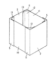
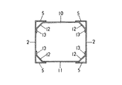
本発明の紙製容器は、図1、図2の基本構造に示されるように、胴部が正面板10、側板2、背面板11、側板2から構成され、それぞれの側板2と胴部貼着片5が折り曲げられてなる直角構造と、正面板10及び背面板11とそれぞれに連接された補強縁片12、補強縁貼着片13が折り曲げられてなる角度構造で貼着接合されることで、直角二等辺三角形状の柱構造がその内部に形成されると共に、正面板10、背面板11の外面にはそれぞれ胴部貼着片5が貼着され、側板2の内面には補強縁貼着片12が貼着されることで、部分的に積層構造となりそれぞれ面として補強される。尚、各々の貼着・接合については、基本的にエマルジョン系糊やホットメルト等による糊着が考えられるが、ステープル封緘による接合も可能である。又、内装容器としては、プラスチックフィルムを用いて製作された袋状容器やプラスチックの薄肉成型品容器などが考えられるが、内容製品の特質に合わせて適宜設計されるものとする。
【0016】
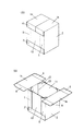
図3、図4で示される実施例は、天板ブランクと、側板2、底板3、側板2の順に連設されたブランクと、正面板ブランク、背面板ブランクとの4ピースからなる構造で、先ず一対の側板2と正面板10と背面板11とで構成される胴部を貼着接合し、次に底板3の上下延長上に設けたそれぞれ正面板10、背面板11への下部貼着片7を貼着接合し、内装容器或いは内容製品を投入した後、天板1の上下延長上に設けたそれぞれ正面板、背面板への上部貼着片6と、左右延長上に設けた側板への上部接合片8を貼着接合して外装が完成する。
【0017】
図5、図6で示される実施例は、側板2、底板3、側板2、天板1、枠部貼着片4の順に連設されたブランクと、正面板ブランク、背面板ブランクとの3ピースの構成からなる構造で、天板1を開蓋した状態で先ず一対の側板2と正面板10と背面板11とで構成される胴部を貼着接合し、次に底板3の上下延長上に設けたそれぞれ正面板10、背面板11への下部貼着片7を貼着接合し、内装容器或いは内容製品を投入した後、天板1を閉じ、枠部貼着片4及び上部貼着片6を順次貼着接合して外装が完成する。
【0018】
図7、図8で示される実施例は、天部構成板1a、側板2、底板3、側板2、重合天部構成板1bの順に連設されたブランクと、正面板ブランク、背面板ブランクとの3ピースからなる構造で、天部構成板1aおよび重合天部構成板1bを開蓋した状態で先ず一対の側板2と正面板10と背面板11とで構成される胴部を貼着接合し、次に底板3の上下延長上に設けたそれぞれ正面板10、背面板11への下部貼着片7を貼着接合し、内装容器或いは内容製品を投入した後、天部構成板1aおよび重合天部構成板1bを貼着し、天部構成板1a及び重合天部構成板1bの上下延長上に設けたそれぞれ正面板10、背面板11への上部貼着片6が正面板10及び背面板11に貼着されて外装が完成する。
【0019】
図9、図10で示される実施例は、天部構成板1a、側板2、底板3、側板2、天部構成板1a´の順に連設されたブランクと、正面板ブランク、背面板ブランクとの3ピースからなる構造で、天部構成板1aおよび天部構成板1a´を開蓋した状態で先ず一対の側板2と正面板10と背面板11とで構成される胴部を貼着接合し、次に底板3の上下延長上に設けたそれぞれ正面板10、背面板11への下部貼着片7を貼着接合し、内装容器或いは内容製品を投入した後、天部構成板1a、1a´を突き合わせて閉じ、封緘テープ50を正面板10、上部貼着片6、突き合わされた天部構成板1a、1a´、上部貼着片6、背面板11に跨って貼着封緘して外装が完成するものである。
【0020】
図11、図12で示される実施例は、天板ブランクと、一対の側板ブランクと、正面板ブランク、背面板ブランク及び底板ブランクとの6ピースからなる構造で、先ず一対の側板2と正面板10と背面板11とで構成される胴部を貼着接合し、次に底板3の上下延長上に設けたそれぞれ正面板10、背面板11への下部貼着片7、左右延長上に設けた側板2への下部接合片9を貼着接合した後、内装容器或いは内容製品を投入し、天板1の上下延長上に設けたそれぞれ正面板10、背面板11への上部貼着片6と、左右延長上に設けた側板2への上部接合片8を貼着接合して外装が完成する。
【0021】
【発明の効果】
以上のごとく、本発明の紙製容器は、外観略直方体の容器であって、筒状胴部の内周四隅部に、三角柱状の補強縁部分が形成されることで、輸送時或いは保管時の積み上げによる座屈及びこれによる内装容器或いは内容製品への荷重による破袋や破損を防止することが出来る。また容器内壁面は略八角形となるので、内装容器或いは内容製品が内壁面に与える内圧や輸送時に生じる衝撃、振動による偏った荷重は分散され、外壁面の変形や破損は防止或いは軽減される効果がある。また各コーナーは空間となっている為に、輸送時あるいは取扱い時の角部落下等衝撃を受けた際にも内装容器或いは内容製品への衝撃が軽減される効果がある。
【0022】
さらに本発明では、筒状胴部を構成する一対の側板、正面板及び背面板がそれぞれ胴部貼着片および補強縁貼着片で貼着接合されている為、それぞれの面の均等な強度上昇が得られる。この為、輸送時或いは保管時の積み上げによる座屈及びこれによる内装容器或いは内容製品への荷重による破袋や破損を防止或いは軽減することが出来る。また内圧による胴部構成各面の胴膨れも軽減される効果がある。
【0023】
従来技術の前述実公平7−9769号や特開平8−282735号では、補強構造構成部分を二重構造にしたり、外装ケースの内側に別体として入れることで、その効果を得ようとしているが、その為必要とされる資材が大きくなり、コストも増大することとなった。本発明では各構成面を必要最小限で接合しているため資材を少なく出来る。試算によれば、実公平7−9769号に開示された補強構造を一体に設けた容器に比して、使用用紙面積比で約3割程度の縮減が図れることで、コスト的にも安価な容器を提供する効果を有する。
【図面の簡単な説明】
【図1】本発明の基本構造を示す斜視図である。
【図2】図1の基本構造の横断面図である。
【図3】本発明の一実施例の斜視図である。
【図4】図3の実施例の展開図である。
【図5】本発明第2の実施例の斜視図である。
【図6】図5の実施例の展開図である。
【図7】本発明第3の実施例の斜視図である。
【図8】図7の実施例の展開図である。
【図9】本発明第4の実施例の斜視図である。
【図10】図9の実施例の展開図である。
【図11】本発明第5の実施例の斜視図である。
【図12】図11の実施例の展開図である。
【符号の説明】
1… 天板
2… 側板
3… 底板
4… 枠部貼着片
5… 胴部貼着片
6… 上部貼着片
7… 下部貼着片
8… 上部接合片
9… 下部接合片
10… 正面板
11… 背面板
12… 補強縁片
13… 補強縁貼着片
1a、1a´… 天部構成板
1b… 重合天部構成板
50… 封緘テープ[0001]
TECHNICAL FIELD OF THE INVENTION
The present invention relates to a paper container, and more particularly, to provide a paper container that prevents deformation and breakage of an outer container that occurs when a large volume of content is stored, and that protects the stored content.
[0002]
[Prior art]
Conventionally, so-called bag-in-boxes, in which products such as large-capacity powders, granules, and liquids are filled into inner bags such as polypropylene and stored in boxes such as cardboard, have been widely used as business paper containers. In terms of disposability and recycling, it has become a popular alternative to metal cans and molded containers. However, paper containers are generally made of corrugated cardboard, and there are many strength problems with large-volume contents, and the outer bag is damaged due to dropping or impact during transportation, and the inner bag is damaged. There was a danger of the contents leaking. In addition, the phenomenon that the outer container is deformed by the inner pressure applied by the inner bag, which is generally called blistering, was considered to lead to breakage if the deformation was remarkable. In these cases, since the outer container is made of paper, more severe conditions such as the effects of rainwater or the like under high humidity or outdoors, and the accumulation during transportation and storage, may occur. Of course, even when the inner bag is not used as described above, when the content is large capacity, large amount, or heavy, deformation and damage of the exterior and damage of the content occur similarly.
[0003]
These require a strong protection function for distribution and storage, and a technology disclosed in Japanese Utility Model Publication No. 7-9969 and Japanese Patent Application Laid-Open No. 8-282735 has a structure in which a reinforcing portion is provided in a body portion. .
Japanese Utility Model Publication No. 7-9969 has a structure in which a corner reinforcing post is integrally formed on the inner periphery of the corner of the cylindrical body, and the internal pressure and other loads applied from the contents are dispersed to prevent the body from bulging. Although it is said that buckling and breakage due to accumulated pressure can be prevented, there is a problem in that the reinforcing material structure is integrated with the main body, which increases the required material development size and increases cost. In addition, due to a different structure in the surface where the affixed portion faces, there was a possibility that glue would be peeled off due to internal pressure in the end plate portion.
[0004]
Further, in Japanese Patent Application Laid-Open No. 8-282735, since the structure is formed by a combination of an outer box and a frame body, the effect of preventing bulging of the body and preventing the containers from being crushed when stacked is increased. It is apparent that the three-layer wall structure has a large required material development dimension and also increases the cost, and there is a problem in economy.
[0005]
[Problems to be solved by the invention]
Therefore, the present invention provides a reinforcing structure at the corners, and further strengthens each structural surface by bonding, thereby preventing deformation and breakage of the outer container due to external force and internal pressure, protecting the contents, and using the same. The aim is to provide an inexpensive paper container by reducing the material as much as possible.
[0006]
[Means for Solving the Problems]
In order to solve the above problems, the paper container of the present invention is constituted by a pair of side plates, a front plate, and a back plate forming a top, a bottom, and a cylindrical body using a sheet-like member such as cardboard or cardboard. A substantially rectangular parallelepiped container, a reinforcing edge piece and a reinforcing edge sticking piece are successively provided on the front plate and the rear plate via creases in the left-right direction, and the pair of side plates are respectively provided in the left-right direction. A torso sticking piece is continuously provided via a crease, and the torso sticking piece is bent at a substantially right angle and is attached to each of the right and left ends of the front plate and the back plate, and the reinforcing member is provided. The edge piece and the reinforcing edge adhesive piece are bent to form a triangular prismatic structure at the four inner corners, and the reinforcing edge adhesive piece is attached to the inner wall slightly closer to the center from the crease of the pair of side plates. And a paper container formed with a cylindrical body.
[0007]
The invention according to
[0008]
According to the invention of
[0009]
The invention according to claim 4 is characterized in that the top plate is continuously provided from one upper end side of the side plate via a fold line, and a frame sticking piece is provided continuously on the extension thereof through a fold line, and On the opposite side of the top plate, an upper sticking piece is continuously provided via a crease, and the frame sticking piece is attached to an upper end of a side plate facing the side plate, and 3. The bottom structure according to
[0010]
The invention according to
[0011]
According to a sixth aspect of the present invention, a top component plate is continuously provided from one upper edge of the side plate and an upper edge of one of the opposing side plates via a fold rule. The upper adhesive pieces are connected to each other through folds on the sides to be joined, and the respective top component plates are abutted at the central portion of the upper part, and the upper adhesive pieces are respectively bent, and the upper adhesive pieces are bent. 3. The bottom structure according to
[0012]
The invention according to
[0013]
The present invention relates to a container having a substantially rectangular parallelepiped container formed of cardboard or corrugated cardboard or the like. Alternatively, the load imbalanced by the internal pressure applied to the inner wall surface by the inner container or the shock or vibration generated during transportation is dispersed, and the deformation load on the outer wall surface is reduced. Further, since each corner is a space, the impact on the contents or the inner container is reduced even when receiving an impact such as a corner drop during transportation or handling. Further, in the present invention, since the body component plate is bonded and joined, the strength of each surface can be increased. For this reason, it is possible to prevent buckling due to stacking during transportation or storage, and the resulting load on the contents or the inner container, breakage such as bag breakage, and the like. In addition, swelling of the body due to internal pressure is reduced.
[0014]
BEST MODE FOR CARRYING OUT THE INVENTION
Hereinafter, the present invention will be described in detail based on examples. FIG. 1 is a perspective view showing a basic structure of the present invention. FIG. 2 is a cross-sectional view of the basic structure of FIG. FIG. 3 is a perspective view of one embodiment of the present invention. FIG. 4 is a development view thereof. FIG. 5 is a perspective view of a second embodiment of the present invention. FIG. 6 is a development view thereof. FIGS. 7A and 7B are perspective views of a third embodiment of the present invention, wherein FIG. 7A shows a completed state, and FIG. FIG. 8 is a development view thereof. 9A and 9B are perspective views of a fourth embodiment of the present invention, wherein FIG. 9A shows a completed state, and FIG. 9B shows a top part opened state. FIG. 10 is an expanded view thereof. FIG. 11 is a perspective view of a fifth embodiment of the present invention. FIG. 12 is an exploded view.
[0015]
As shown in the basic structure of FIGS. 1 and 2, the paper container of the present invention has a body composed of a
[0016]
The embodiment shown in FIGS. 3 and 4 has a structure including four pieces of a top plate blank, a
[0017]
The embodiment shown in FIG. 5 and FIG. 6 has a blank consisting of a
[0018]
The embodiment shown in FIG. 7 and FIG. 8 is a blank in which a top component plate 1a, a
[0019]
The embodiment shown in FIG. 9 and FIG. 10 is composed of a blank sequentially provided in the order of the top component plate 1a, the
[0020]
The embodiment shown in FIGS. 11 and 12 has a structure including six pieces of a top plate blank, a pair of side plate blanks, a front plate blank, a back plate blank, and a bottom plate blank. The torso composed of the
[0021]
【The invention's effect】
As described above, the paper container of the present invention is a container having a substantially rectangular parallelepiped appearance, and a triangular prism-shaped reinforcing edge portion is formed at the inner four corners of the cylindrical body, so that the paper container can be transported or stored. Buckling due to the stacking of the materials and the breakage or breakage due to the load on the inner container or the content product due to the buckling can be prevented. In addition, since the inner wall surface of the container is substantially octagonal, the uneven pressure caused by the internal pressure applied to the inner wall surface of the inner container or the content product, the impact generated during transportation, and the vibration is dispersed, and the deformation and breakage of the outer wall surface is prevented or reduced. effective. Further, since each corner is a space, there is an effect that the impact on the inner container or the content product is reduced even when receiving an impact such as a corner drop during transportation or handling.
[0022]
Furthermore, in the present invention, the pair of side plates, the front plate, and the back plate that constitute the cylindrical body are bonded and bonded with the body sticking pieces and the reinforcing edge sticking pieces, respectively, so that the uniform strength of each surface is achieved. A rise is obtained. Therefore, it is possible to prevent or reduce buckling due to stacking during transportation or storage, and thereby, breakage or breakage of the package due to the load on the inner container or the content product. In addition, there is an effect that the swelling of each body constituting surface due to the internal pressure is also reduced.
[0023]
In the above-mentioned Japanese Utility Model Publication No. 7-9969 and Japanese Patent Application Laid-Open No. 8-282735, the effect is intended to be obtained by forming the reinforcing structure component into a double structure or by putting it separately inside the outer case. Therefore, the required materials are increased, and the cost is also increased. In the present invention, materials can be reduced because the constituent surfaces are joined to the minimum necessary. According to trial calculations, it is possible to achieve a reduction of about 30% in the area ratio of the used paper as compared with the container integrally provided with the reinforcing structure disclosed in Japanese Utility Model Publication No. 7-9969, thereby reducing the cost. It has the effect of providing a container.
[Brief description of the drawings]
FIG. 1 is a perspective view showing a basic structure of the present invention.
FIG. 2 is a cross-sectional view of the basic structure of FIG.
FIG. 3 is a perspective view of one embodiment of the present invention.
FIG. 4 is a development view of the embodiment of FIG. 3;
FIG. 5 is a perspective view of a second embodiment of the present invention.
FIG. 6 is a development view of the embodiment of FIG. 5;
FIG. 7 is a perspective view of a third embodiment of the present invention.
FIG. 8 is a development view of the embodiment of FIG. 7;
FIG. 9 is a perspective view of a fourth embodiment of the present invention.
FIG. 10 is a development view of the embodiment of FIG. 9;
FIG. 11 is a perspective view of a fifth embodiment of the present invention.
FIG. 12 is a development view of the embodiment of FIG. 11;
[Explanation of symbols]
DESCRIPTION OF SYMBOLS 1 ...
Claims (7)
Priority Applications (1)
| Application Number | Priority Date | Filing Date | Title |
|---|---|---|---|
| JP2002179169A JP2004018077A (en) | 2002-06-19 | 2002-06-19 | Paper-made container |
Applications Claiming Priority (1)
| Application Number | Priority Date | Filing Date | Title |
|---|---|---|---|
| JP2002179169A JP2004018077A (en) | 2002-06-19 | 2002-06-19 | Paper-made container |
Publications (1)
| Publication Number | Publication Date |
|---|---|
| JP2004018077A true JP2004018077A (en) | 2004-01-22 |
Family
ID=31176668
Family Applications (1)
| Application Number | Title | Priority Date | Filing Date |
|---|---|---|---|
| JP2002179169A Pending JP2004018077A (en) | 2002-06-19 | 2002-06-19 | Paper-made container |
Country Status (1)
| Country | Link |
|---|---|
| JP (1) | JP2004018077A (en) |
Cited By (12)
| Publication number | Priority date | Publication date | Assignee | Title |
|---|---|---|---|---|
| JP2006327601A (en) * | 2005-05-24 | 2006-12-07 | Toppan Printing Co Ltd | Single paper outer packaging box for bag-in box, and fabricating apparatus for the box |
| JP2011206914A (en) * | 2010-03-26 | 2011-10-20 | Brother Industries Ltd | Tape cassette |
| US8740482B2 (en) | 2009-03-31 | 2014-06-03 | Brother Kogyo Kabushiki Kaisha | Tape printer |
| US8757907B2 (en) | 2009-03-31 | 2014-06-24 | Brother Kogyo Kabushiki Kaisha | Tape cassette |
| US8764326B2 (en) | 2009-03-31 | 2014-07-01 | Brother Kogyo Kabushiki Kaisha | Tape cassette |
| US8770877B2 (en) | 2008-12-25 | 2014-07-08 | Brother Kogyo Kabushiki Kaisha | Tape printer |
| US9132682B2 (en) | 2009-03-31 | 2015-09-15 | Brother Kogyo Kabushiki Kaisha | Tape unit and tape cassette |
| US9498998B2 (en) | 2008-12-25 | 2016-11-22 | Brother Kogyo Kabushiki Kaisha | Tape cassette |
| US9539837B2 (en) | 2009-12-16 | 2017-01-10 | Brother Kogyo Kabushiki Kaisha | Tape cassette |
| US9566808B2 (en) | 2009-03-31 | 2017-02-14 | Brother Kogyo Kabushiki Kaisha | Tape cassette |
| US9573401B2 (en) | 2009-06-30 | 2017-02-21 | Brother Kogyo Kabushiki Kaisha | Tape cassette |
| US9656495B2 (en) | 2009-12-28 | 2017-05-23 | Brother Kogyo Kabushiki Kaisha | Tape cassette |
-
2002
- 2002-06-19 JP JP2002179169A patent/JP2004018077A/en active Pending
Cited By (63)
| Publication number | Priority date | Publication date | Assignee | Title |
|---|---|---|---|---|
| JP2006327601A (en) * | 2005-05-24 | 2006-12-07 | Toppan Printing Co Ltd | Single paper outer packaging box for bag-in box, and fabricating apparatus for the box |
| JP4677827B2 (en) * | 2005-05-24 | 2011-04-27 | 凸版印刷株式会社 | Outer box for bag-in-box using single paper and manufacturing apparatus thereof |
| US9656496B2 (en) | 2008-12-25 | 2017-05-23 | Brother Kogyo Kabushiki Kaisha | Tape cassette |
| US10744798B2 (en) | 2008-12-25 | 2020-08-18 | Brother Kogyo Kabushiki Kaisha | Tape cassette |
| US9649861B2 (en) | 2008-12-25 | 2017-05-16 | Brother Kogyo Kabushiki Kaisha | Tape cassette |
| US10661589B2 (en) | 2008-12-25 | 2020-05-26 | Brother Kogyo Kabushiki Kaisha | Tape cassette |
| US10189284B2 (en) | 2008-12-25 | 2019-01-29 | Brother Kogyo Kabushiki Kaisha | Tape cassette |
| US8770877B2 (en) | 2008-12-25 | 2014-07-08 | Brother Kogyo Kabushiki Kaisha | Tape printer |
| US9855779B2 (en) | 2008-12-25 | 2018-01-02 | Brother Kogyo Kabushiki Kaisha | Tape cassette |
| US9751349B2 (en) | 2008-12-25 | 2017-09-05 | Brother Kogyo Kabushiki Kaisha | Tape cassette |
| US11479053B2 (en) | 2008-12-25 | 2022-10-25 | Brother Kogyo Kabushiki Kaisha | Tape cassette |
| US9656497B2 (en) | 2008-12-25 | 2017-05-23 | Brother Kogyo Kabushiki Kaisha | Tape cassette |
| US9511609B2 (en) | 2008-12-25 | 2016-12-06 | Brother Kogyo Kabushiki Kaisha | Tape cassette |
| US11285749B2 (en) | 2008-12-25 | 2022-03-29 | Brother Kogyo Kabushiki Kaisha | Tape cassette |
| US9682584B2 (en) | 2008-12-25 | 2017-06-20 | Brother Kogyo Kabushiki Kaisha | Tape cassette |
| US9566812B2 (en) | 2008-12-25 | 2017-02-14 | Brother Kogyo Kabushiki Kaisha | Tape cassette |
| US9493016B2 (en) | 2008-12-25 | 2016-11-15 | Brother Kogyo Kabushiki Kaisha | Tape cassette |
| US9498998B2 (en) | 2008-12-25 | 2016-11-22 | Brother Kogyo Kabushiki Kaisha | Tape cassette |
| US9539838B2 (en) | 2008-12-25 | 2017-01-10 | Brother Kogyo Kabushiki Kaisha | Tape Cassette |
| US9533522B2 (en) | 2008-12-25 | 2017-01-03 | Brother Kogyo Kabushiki Kaisha | Tape cassette |
| US9498997B2 (en) | 2008-12-25 | 2016-11-22 | Brother Kogyo Kabushiki Kaisha | Tape cassette |
| US9511610B2 (en) | 2008-12-25 | 2016-12-06 | Brother Kogyo Kabushiki Kaisha | Tape cassette |
| US9511611B2 (en) | 2008-12-25 | 2016-12-06 | Brother Kogyo Kabushiki Kaisha | Tape cassette |
| US9522556B2 (en) | 2008-12-25 | 2016-12-20 | Brother Kogyo Kabushiki Kaisha | Tape cassette |
| US9592692B2 (en) | 2009-03-31 | 2017-03-14 | Brother Kogyo Kabushiki Kaisha | Tape cassette |
| US8764326B2 (en) | 2009-03-31 | 2014-07-01 | Brother Kogyo Kabushiki Kaisha | Tape cassette |
| US11945217B2 (en) | 2009-03-31 | 2024-04-02 | Brother Kogyo Kabushiki Kaisha | Tape cassette |
| US9498987B2 (en) | 2009-03-31 | 2016-11-22 | Brother Kogyo Kabushiki Kaisha | Tape cassette |
| US9566808B2 (en) | 2009-03-31 | 2017-02-14 | Brother Kogyo Kabushiki Kaisha | Tape cassette |
| US9427988B2 (en) | 2009-03-31 | 2016-08-30 | Brother Kogyo Kabushiki Kaisha | Tape cassette |
| US11707938B2 (en) | 2009-03-31 | 2023-07-25 | Brother Kogyo Kabushiki Kaisha | Tape cassette |
| US9409425B2 (en) | 2009-03-31 | 2016-08-09 | Brother Kogyo Kabushiki Kaisha | Tape cassette |
| US9616690B2 (en) | 2009-03-31 | 2017-04-11 | Brother Kogyo Kabushiki Kaisha | Tape cassette |
| US9403389B2 (en) | 2009-03-31 | 2016-08-02 | Brother Kogyo Kabushiki Kaisha | Tape cassette |
| US9656488B2 (en) | 2009-03-31 | 2017-05-23 | Brother Kogyo Kabushiki Kaisha | Tape cassette |
| US9381756B2 (en) | 2009-03-31 | 2016-07-05 | Brother Kogyo Kabushiki Kaisha | Tape cassette |
| US8740482B2 (en) | 2009-03-31 | 2014-06-03 | Brother Kogyo Kabushiki Kaisha | Tape printer |
| US9370949B2 (en) | 2009-03-31 | 2016-06-21 | Brother Kogyo Kabushiki Kaisha | Tape cassette |
| US11254149B2 (en) | 2009-03-31 | 2022-02-22 | Brother Kogyo Kabushiki Kaisha | Tape cassette |
| US9346296B2 (en) | 2009-03-31 | 2016-05-24 | Brother Kogyo Kabushiki Kaisha | Tape cassette |
| US9132682B2 (en) | 2009-03-31 | 2015-09-15 | Brother Kogyo Kabushiki Kaisha | Tape unit and tape cassette |
| US11052685B2 (en) | 2009-03-31 | 2021-07-06 | Brother Kogyo Kabushiki Kaisha | Tape cassette |
| US9011028B2 (en) | 2009-03-31 | 2015-04-21 | Brother Kogyo Kabushiki Kaisha | Tape cassette |
| US9498988B2 (en) | 2009-03-31 | 2016-11-22 | Brother Kogyo Kabushiki Kaisha | Tape cassette |
| US10201993B2 (en) | 2009-03-31 | 2019-02-12 | Brother Kogyo Kabushiki Kaisha | Tape cassette |
| US10201988B2 (en) | 2009-03-31 | 2019-02-12 | Brother Kogyo Kabushiki Kaisha | Tape cassette |
| US10226949B2 (en) | 2009-03-31 | 2019-03-12 | Brother Kogyo Kabushiki Kaisha | Tape cassette |
| US8757907B2 (en) | 2009-03-31 | 2014-06-24 | Brother Kogyo Kabushiki Kaisha | Tape cassette |
| US10744802B2 (en) | 2009-03-31 | 2020-08-18 | Brother Kogyo Kabushiki Kaisha | Tape cassette |
| US10618325B2 (en) | 2009-03-31 | 2020-04-14 | Brother Kogyo Kabushiki Kaisha | Tape cassette |
| US8764325B2 (en) | 2009-03-31 | 2014-07-01 | Brother Kogyo Kabushiki Kaisha | Tape cassette |
| US10675894B2 (en) | 2009-03-31 | 2020-06-09 | Brother Kogyo Kabushiki Kaisha | Tape cassette |
| US9802432B2 (en) | 2009-06-30 | 2017-10-31 | Brother Kogyo Kabushiki Kaisha | Tape cassette |
| US11225099B2 (en) | 2009-06-30 | 2022-01-18 | Brother Kogyo Kabushiki Kaisha | Tape cassette |
| US9676217B2 (en) | 2009-06-30 | 2017-06-13 | Brother Kogyo Kabushiki Kaisha | Tape cassette |
| US9573401B2 (en) | 2009-06-30 | 2017-02-21 | Brother Kogyo Kabushiki Kaisha | Tape cassette |
| US10265976B2 (en) | 2009-12-16 | 2019-04-23 | Brother Kogyo Kabushiki Kaisha | Tape cassette |
| US11235600B2 (en) | 2009-12-16 | 2022-02-01 | Brother Kogyo Kabushiki Kaisha | Tape cassette |
| US9539837B2 (en) | 2009-12-16 | 2017-01-10 | Brother Kogyo Kabushiki Kaisha | Tape cassette |
| US10265982B2 (en) | 2009-12-28 | 2019-04-23 | Brother Kogyo Kabushiki Kaisha | Tape cassette |
| US11135862B2 (en) | 2009-12-28 | 2021-10-05 | Brother Kogyo Kabushiki Kaisha | Tape cassette with indicator portion having pressing and non-pressing portion for indentifying tape type |
| US9656495B2 (en) | 2009-12-28 | 2017-05-23 | Brother Kogyo Kabushiki Kaisha | Tape cassette |
| JP2011206914A (en) * | 2010-03-26 | 2011-10-20 | Brother Industries Ltd | Tape cassette |
Similar Documents
| Publication | Publication Date | Title |
|---|---|---|
| JPH072463Y2 (en) | Container with internal bag | |
| US9016555B2 (en) | Flexible liner and bag-in-box container systems | |
| AU705150B2 (en) | Minimal shipping container and method of construction | |
| CA1051392A (en) | Two cell bulk container | |
| US5450998A (en) | Fabricated on demand totes | |
| JP2004018077A (en) | Paper-made container | |
| US7784674B2 (en) | Bulk materials container | |
| JP2000085789A (en) | Synthetic resin bag with assist board | |
| US7229003B2 (en) | Bulk materials container | |
| JP4202700B2 (en) | Inner bag storage container | |
| JPH079769Y2 (en) | Corner reinforced inner bag container with thin plastic container or bag inside | |
| JP3305125B2 (en) | Bag-in-box with blister prevention function | |
| CN211033406U (en) | Packing box | |
| KR200339470Y1 (en) | Packing ease one acceptance box | |
| JP3220999U (en) | Cardboard box | |
| CN211108464U (en) | Packing box | |
| CN215514568U (en) | Inverted trapezoidal packaging box | |
| JP4099855B2 (en) | Buffer packaging equipment | |
| JPS6128742Y2 (en) | ||
| CN210000734U (en) | lipstick packing box | |
| JP5051871B2 (en) | Multistage displayable packaging box | |
| JPH0441064Y2 (en) | ||
| JPH0327966Y2 (en) | ||
| JPH0635928Y2 (en) | Corrugated cardboard box for preventing load collapse | |
| JP2521793Y2 (en) | Carton for packing powder etc. |
Legal Events
| Date | Code | Title | Description |
|---|---|---|---|
| A711 | Notification of change in applicant |
Free format text: JAPANESE INTERMEDIATE CODE: A711 Effective date: 20050221 |
|
| A521 | Written amendment |
Free format text: JAPANESE INTERMEDIATE CODE: A821 Effective date: 20050221 |
|
| A621 | Written request for application examination |
Free format text: JAPANESE INTERMEDIATE CODE: A621 Effective date: 20050520 |
|
| RD05 | Notification of revocation of power of attorney |
Free format text: JAPANESE INTERMEDIATE CODE: A7425 Effective date: 20050629 |
|
| RD02 | Notification of acceptance of power of attorney |
Effective date: 20050713 Free format text: JAPANESE INTERMEDIATE CODE: A7422 |
|
| A977 | Report on retrieval |
Effective date: 20071127 Free format text: JAPANESE INTERMEDIATE CODE: A971007 |
|
| A131 | Notification of reasons for refusal |
Free format text: JAPANESE INTERMEDIATE CODE: A131 Effective date: 20071211 |
|
| A02 | Decision of refusal |
Free format text: JAPANESE INTERMEDIATE CODE: A02 Effective date: 20080417 |