JP2005298031A - Packing material for eaves - Google Patents
Packing material for eaves Download PDFInfo
- Publication number
- JP2005298031A JP2005298031A JP2004119394A JP2004119394A JP2005298031A JP 2005298031 A JP2005298031 A JP 2005298031A JP 2004119394 A JP2004119394 A JP 2004119394A JP 2004119394 A JP2004119394 A JP 2004119394A JP 2005298031 A JP2005298031 A JP 2005298031A
- Authority
- JP
- Japan
- Prior art keywords
- eaves
- box
- packing material
- main body
- packing
- Prior art date
- Legal status (The legal status is an assumption and is not a legal conclusion. Google has not performed a legal analysis and makes no representation as to the accuracy of the status listed.)
- Pending
Links
Images
Landscapes
- Stackable Containers (AREA)
- Buffer Packaging (AREA)
- Packaging Of Annular Or Rod-Shaped Articles, Wearing Apparel, Cassettes, Or The Like (AREA)
Abstract
【課題】 梱包費の増加および梱包の手間の増大を抑制し、軒樋に損傷を与えることなく
運搬し得る軒樋用梱包材を提供する。
【解決手段】 軒樋17を収容する長尺状の箱体(10)を形成するための梱包材10。
梱包材10は、両端開放の筒体を構成する本体11および該本体の両側に形成され、両端
を閉鎖するための端壁を構成する一対のサイドフラップ12を備える。サイドフラップ1
2の少なくとも一方は、筒体から該筒体の長手方向と直角に外方へ突出可能な張出部15
を有する。張出部15は、衝撃を受けたとき、その変形によって衝撃を緩和することによ
り、箱体(10)の内部の軒樋17を衝撃から保護する。
【選択図】 図1
PROBLEM TO BE SOLVED: To provide an eaves packaging material that can be transported without damaging the eaves while suppressing an increase in packing cost and packing labor.
SOLUTION: A packing material 10 for forming a long box (10) for accommodating eaves troughs (17).
The packing material 10 includes a main body 11 constituting a cylindrical body having both ends open, and a pair of side flaps 12 formed on both sides of the main body and constituting end walls for closing both ends. Side flap 1
At least one of the two projecting portions 15 that can project outward from the cylinder at right angles to the longitudinal direction of the cylinder.
Have When the overhanging portion 15 receives an impact, the overhanging portion 17 protects the eaves 17 inside the box (10) from the impact by relaxing the impact by deformation.
[Selection] Figure 1
Description
本発明は、複数の軒樋を保管、運搬するのに適した箱体を形成するための軒樋用梱包材
に関する。
The present invention relates to a packing material for eaves for forming a box suitable for storing and transporting a plurality of eaves.
軒樋の運搬あるいはその保管には、一般的に、例えば段ボール紙のようなシート状材料
からなる梱包材を組み立てて形成された長尺状の箱体が用いられており、この箱体内に複
数の軒樋が相互に嵌合された積層状態で収容される。
In order to transport or store the eaves, generally, a long box formed by assembling a packing material made of a sheet-like material such as corrugated paper is used. Are housed in a stacked state in which the eaves are fitted together.
運搬中の箱体内での軒樋の遊びによる踊りを防止するために、スペーサを配置すること
が提案されている(例えば、特許文献1および2参照。)。
In order to prevent dancing due to play of eaves in the box during transportation, it has been proposed to arrange spacers (see, for example, Patent Documents 1 and 2).
このスペーサによって、運搬中に箱体内で軒樋が踊りを生じることを防止することがで
き、この踊りによって生じる軒樋の変形や軒樋同士の当接による損傷を防止することがで
きる。
By this spacer, it is possible to prevent the eaves from dancing in the box during transportation, and it is possible to prevent the eaves from being deformed by the dance and from being damaged due to contact between the eaves.
しかしながら、運搬中に、例えば箱体をその端部から地面に落下させるような事故が生
じ、そのため、箱体内の軒樋の重量が地面に当接する箱体の端部の角に作用すると、箱の
角が大きく変形し、内部に収容された軒樋の端部にひびや割れを生じることがある。
However, during transportation, for example, an accident that drops the box from the end to the ground occurs, so if the weight of the eaves in the box acts on the corner of the end of the box that contacts the ground, the box The corners of the plate may be greatly deformed, and cracks and cracks may occur at the ends of the eaves housed inside.
このような事故から箱体内の軒樋を保護するために、箱体の両端に補強のための保護部
材を装着することが提案されている(例えば、特許文献3参照。)。
In order to protect the eaves inside the box from such an accident, it has been proposed to attach protective members for reinforcement to both ends of the box (for example, see Patent Document 3).
この保護部材の装着によって、箱体の端部が補強されることから、箱体の角の潰れが防
止され、これにより、箱体の角の潰れによる軒樋の損傷を防止することができる。
しかしながら、箱体の端部に装着される保護部材は、箱体を構成する梱包材とは別体の
材料で予め形成しておく必要があり、また梱包材の組み立て工程とは別に、保護部材を組
み立てる必要がある。そのため、軒樋の梱包のための材料費の増加および梱包の手間が増
大するという問題があった。
However, the protective member attached to the end of the box needs to be formed in advance from a separate material from the packing material constituting the box, and the protective member is separate from the packaging material assembly process. Need to assemble. Therefore, there has been a problem that the material cost for packing the eaves is increased and the labor for packing is increased.
そこで、本発明の目的は、梱包費の増加および梱包の手間の増大を抑制し、軒樋をこれ
に損傷を与えることなく運搬し得る軒樋用梱包材を提供することにある。
SUMMARY OF THE INVENTION An object of the present invention is to provide an eaves packaging material that can suppress an increase in packing cost and packing labor and can transport eaves without damaging them.
本発明は、軒樋を収容する長尺状の箱体を形成するための軒樋用梱包材であって両端開
放の筒体を構成すべく両側が相互に繋ぎ合わされる本体と、該本体に連続して該本体の両
端縁に形成され前記筒体の端壁を構成する一対のサイドフラップとを備え、該サイドフラ
ップの少なくとも一方は前記筒体から該筒体の長手方向と直角に外方へ突出可能な張出部
を有することを特徴とする。
The present invention is a packing material for eaves for forming an elongate box that accommodates eaves, and a main body in which both sides are connected to each other to form a cylindrical body open at both ends, and the main body A pair of side flaps continuously formed at both end edges of the main body and constituting an end wall of the cylindrical body, and at least one of the side flaps is outward from the cylindrical body at right angles to the longitudinal direction of the cylindrical body It has the overhang | projection part which can project to the side.
本発明に係る前記梱包材として、例えば、段ボール紙あるいはその他の折り曲げ可能の
シート状材料を用いることができる。前記筒体の端壁を構成する前記サイドフラップに形
成され前記筒体からその外方へ突出する前記張出部は、衝撃を受けると、その変形によっ
て衝撃を緩和する作用をなす。従って、前記箱体の内部に収容された軒樋が衝撃から保護
されることから、内部に収容された軒樋に衝撃でひびや損傷が生じることを防止すること
ができる。
As the packing material according to the present invention, for example, corrugated paper or other foldable sheet-like material can be used. When the overhanging portion formed on the side flap constituting the end wall of the cylindrical body and projecting outward from the cylindrical body is subjected to an impact, it acts to alleviate the impact by its deformation. Therefore, since the eaves housed inside the box is protected from the impact, it is possible to prevent the eaves housed inside from being cracked or damaged by the impact.
前記筒体の外方に突出する前記張出部は、前記箱体の端部を補強すべく前記筒体に沿っ
て折り返すことができる。この張出部の折り返しにより、従来のような別体の保護部材を
用いることなく、箱体の端部の角をより効果的に補強することができ、箱体の落下による
角の潰れをより確実に防止することができる。
The projecting portion protruding outward from the cylindrical body can be folded back along the cylindrical body to reinforce the end of the box. By folding the overhanging portion, the corners of the end of the box can be more effectively reinforced without using a separate protective member as in the past, and the corners can be more easily crushed by dropping the box. It can be surely prevented.
前記本体の前記端縁または該端縁に連続する前記サイドフラップの基部に、前記張出部
に対応して該張出部を受け入れ可能な形状の凹所を形成することができる。
A recess having a shape capable of receiving the overhanging portion corresponding to the overhanging portion can be formed in the end edge of the main body or the base portion of the side flap continuous to the end edge.
梱包材からなる一つの箱体の前記凹所と、他の梱包材からなる他の箱体の前記サイドフ
ラップの張出部とが向き合うように、複数の箱体を例えば上下方向へ整列して積み重ねる
場合、上下方向に相互に対応する前記凹所および前記張出部を相互に嵌合させることがで
きる。したがって、この場合、複数の箱体間に隙間が生じること無く、両箱体を相互に密
着させて配置させることができる。しかも、前記凹所および前記張出部は、これらを相互
に嵌合させることにより、箱体間の位置決め作用をなすことから、箱体間にずれを生じる
ことなく、この箱体を整列して積み重ねることが可能となる。
A plurality of boxes are aligned vertically, for example, so that the recess of one box made of a packing material faces the protruding portion of the side flap of another box made of another packing material. In the case of stacking, the recess and the overhang corresponding to each other in the vertical direction can be fitted to each other. Therefore, in this case, the two boxes can be placed in close contact with each other without causing a gap between the plurality of boxes. In addition, since the recess and the overhanging portion are engaged with each other to form a positioning action between the boxes, the boxes are aligned without causing any deviation between the boxes. It becomes possible to stack.
本発明によれば、前記梱包材によって形成される箱体の端部に該箱体と別部材の保護部
材を装着することなく、前記箱体端部に作用する衝撃を緩和しあるいは端部を補強するこ
とができるので、梱包費用あるいは組み立て手間の従来のような増大を招くことなく確実
に軒樋を保護することができる。
According to the present invention, the shock acting on the end of the box is reduced or the end is not attached to the end of the box formed by the packing material, without attaching a protective member which is a separate member from the box. Since it can reinforce, the eaves can be reliably protected without incurring a conventional increase in packing cost or assembly time.
本発明の特徴を図示の実施例に沿って説明する。 The features of the present invention will be described along the illustrated embodiments.
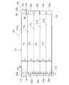
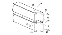
本発明に係る梱包材10は、図1に示すように、例えばダンボール紙のような折り曲げ
可能なシート状部材からなる。梱包材10は、全体に矩形の本体11と、該本体に連続し
て形成された複数のサイドフラップ12(12a、12b〜12e)とを有する。
As shown in FIG. 1, the
本体11の長手方向には、互いに平行な折り目線13が形成されている。これら折り目
線13によって、本体11には、頂壁部11a、側壁部11b、底壁部11c、側壁部1
1dおよび重複部11eが順次区画されている。図示の例では、頂壁部11a、底壁部1
1cおよび重複部11eは、本体11の長手方向と直角な横方向へ寸法L1が与えられ、
側壁部11bおよび11dは、同様に寸法L2が与えられている。
In the longitudinal direction of the
1d and the overlapping
1c and the overlapping
The
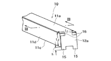
これら各壁部11a〜11eは、折り目線13に沿った山折りあるいは谷折りによって
、頂壁部11aが重複部11eよりも外側に位置するように互いに重ね会わせることがで
きる。この頂壁部11aと重複部11eとの重ね合わせによる本体11の両側での繋ぎ合
わせにより、図2および図3に示すように、幅寸法L1および高さ寸法L2を有する矩形
断面形状を有する筒体が、各壁部11a〜11eで構成される。
These
再び図1を参照するに、各サイドフラップ12(12a、12b〜12e)は、本体1
1の両端縁に連続的に形成されている。頂壁部11aを除く両側壁部11b、11d、底
壁部11cおよび重複部11eの各両端縁に形成された各一対のサイドフラップ12b〜
12eは、本体11の両端縁に形成された折り目線14、14により、本体11から区画
されている。
Referring again to FIG. 1, each side flap 12 (12 a, 12 b to 12 e)
1 is formed continuously at both end edges. A pair of
12 e is partitioned from the
両側壁部11b、11dに形成されたサイドフラップ12bおよび12dには、高さ寸
法L2の方向に沿ってこの高さ寸法L2よりも小さな寸法L3が与えられ、また底壁部1
1cおよび重複部11eに形成されたサイドフラップ12cおよび12eには、幅方向寸
法L1の方向に沿ってこの幅方向寸法L1よりも小さな寸法L4が与えられている。また
、これらサイドフラップ12b〜12eには、幅寸法L1および高さ寸法L2よりも小さ
な互いに等寸の張出寸法L5が与えられている。
The
The
従って、各壁部11a〜11eで筒体を構成し、その後、これらのサイドフラップ12
b〜12eを折り目線14で折り曲げたとき、各壁部11a〜11eにより構成される前
記筒体から各サイドフラップ12b〜12eが外方に張り出すことはなく、前記筒体の横
断面形状内で相互に重なり合う。
Therefore, each
When b-12e is bent along the
他方、頂壁部11aの両端縁には、先に折り曲げられた各サイドフラップ12b〜12
eの最も外側に位置するように折り曲げられる一対のサイドフラップ12aおよび12a
が形成されている。
On the other hand, the side flaps 12b to 12 which are bent first are formed at both end edges of the
a pair of
Is formed.
各サイドフラップ12aは、頂壁部11aの幅寸法L1にほぼ等しい幅寸法を有し、頂
壁部11aの各端縁から遠ざかる方向へ伸長する。各サイドフラップ12aの伸長端には
、側壁部11b、11dの高さ寸法L2に等しい長さを越えて伸長する張出部15が形成
されている。図示の例では、一対の張出部15が、サイドフラップ12aの幅方向へ互い
に間隔をおいて各サイドフラップ12aの両側に形成されている。
Each
また、各サイドフラップ12aの基部には、張出部15の形状に対応した一対の凹所1
6が形成されている。各凹所16は、各サイドフラップ12aの両側に形成された各張出
部15を受け入れるに充分な大きさおよび形状を有し、図1に示す例では、切欠き部によ
り形成されている。
Further, a pair of recesses 1 corresponding to the shape of the overhanging
6 is formed. Each
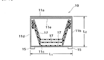
前記したように、各壁部11a〜11eにより幅寸法L1および高さ寸法L2を有する
矩形断面形状を有する筒体が構成された状態で、該筒体内に図3に示すように例えば3.
6mの長さを有する複数の軒樋17が互いに嵌合された状態で収容される。収容される全
軒樋17の重量は例えば20Kg程度である。
As described above, in the state where the cylindrical body having the rectangular cross section having the width dimension L1 and the height dimension L2 is constituted by the
A plurality of
軒樋17を収容した状態で、前記したように、頂壁部11aを除く両側壁部11b、1
1d、底壁部11cおよび重複部11eの各両端縁に形成された各一対のサイドフラップ
12b、12c、12d、12eが折り曲げられ、その後、これらのサイドフラップ12
b〜12eを覆うように、頂壁部11aに形成された各サイドフラップ12aが折り曲げ
られる。このサイドフラップ12aは、例えば接着テープを用いて前記筒体に固着され、
これらのサイドフラップ12a〜12eの重なりにより、前記各壁部11a〜11eで構
成された筒体の端壁が構成され、これにより内部に軒樋17を収容した箱体が構成される
。サイドフラップ12aは、必要に応じて、その直下のサイドフラップ12b、12c、
12dまたは12eに適宜、接着テープあるいは接着剤を用いて固着することができる。
In the state where the
1d, the pair of
Each
By overlapping these
It can be fixed to 12d or 12e as appropriate using an adhesive tape or an adhesive.
頂壁部11aに形成された各サイドフラップ12aには、側壁部11b、11dの高さ
寸法L2に等しい長さを越えて伸長する張出部15が形成されていることから、サイドフ
ラップ12aを折り曲げた状態では、図2に示すように、その張出部15が底壁部11c
から下方に向けて突出する。この突出寸法hは、前記したように、梱包重量が約20Kg
であるとき、例えば5mm以上となるように形成される。
Since each
Projects downward from As described above, the projecting dimension h has a packing weight of about 20 kg.
For example, it is formed to be 5 mm or more.
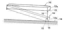
本発明に係る梱包材10は、軒樋17の運搬に用いられる。この運搬のために、図3に
示したように、梱包材10によって構成された箱体の内部に軒樋17が収納されて運搬さ
れるが、運搬途中、例えば図4に示すように、前記箱体の一端が地面18に落下する事故
が生じ、この落下によって箱体の底壁部11cから突出して形成された張出部15が地面
18に強く当たると、この張出部15が変形し、潰れる。
The
張出部15は、その変形によって衝撃のエネルギーを緩和する。この張出部15の衝撃
緩和作用によって、前記箱の角の潰れが防止され、また、前記箱体の内部に収容された軒
樋17が衝撃から保護される。
The overhanging
その結果、梱包材10によって構成される箱体に従来のような端部保護部材を装着する
ことなく、梱包材10の落下時の衝撃から、この梱包材10で構成された箱体内に収容さ
れた軒樋17にひびや損傷が生じることを防止することができる。
As a result, it is accommodated in the box comprised by this packing
また、図5に示すように、梱包材10で構成された各箱体(10、10)に軒樋17を
収容した状態で、それぞれを相互に積み重ねて保管することができる。この保管では、下
方の箱体(10)の凹所16と、上方の箱体(10)のサイドフラップ12aの張出部1
5とが向き合うように、複数の箱体(10、10)が上下方向へ整列して積み重ねられる
。この積み重ねにより、上下方向に相互に対応する凹所16および張出部15を相互に嵌
合させることができる。
Moreover, as shown in FIG. 5, in the state which accommodated the
A plurality of boxes (10, 10) are stacked in the vertical direction so that 5 faces each other. By this stacking, the
従って、この積み重ねで、複数の箱体(10、10)間に隙間が生じること無く、上方
の箱体(10)の底部と下方の箱体(10)の頂部とを相互に密着させて配置させること
ができる。さらに、凹所16および張出部15は、相互に嵌合することにより、両箱体(
10、10)間の位置決め作用をなすことから、該箱体間にずれを生じることなくこの箱
体(10、10)を上下方向に整列して積み重ねることが容易となる。
Therefore, in this stacking, the bottom of the upper box (10) and the top of the lower box (10) are arranged in close contact with each other without any gaps between the plurality of boxes (10, 10). Can be made. Furthermore, the
10 and 10), the box bodies (10, 10) can be easily aligned and stacked in the vertical direction without causing a shift between the box bodies.
各サイドフラップ12aの両側に一対の張出部15を形成することに代えて、各サイド
フラップ12aの中央部に単一の張出部15を形成することができる。しかしながら、箱
体の落下時に損傷を受け易い角を効果的に保護する上で、前記したように、サイドフラッ
プ12aの両側に一対の張出部15を形成することが望ましい。
Instead of forming a pair of
また、張出部15は、各サイドフラップ12aの先端に形成することに代えて、あるい
は先端に形成することに加えて、該サイドフラップの両側に形成することができる。また
、各サイドフラップ12aに代えて、サイドフラップ12(12a〜12e)の折り曲げ
が妨げられない限り、適宜、他のサイドフラップ12b〜12eに形成することができる
。
Further, the overhanging
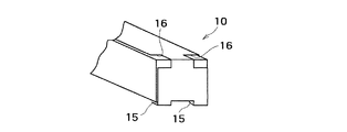
また、図6に示されているように、サイドフラップ12aに形成された張出部15の先
端を前記筒体を構成する底壁部11cに向けて折り返すことができ、この折返し部を底壁
部11cに接着剤等を用いて固着することができる。
Further, as shown in FIG. 6, the tip of the overhanging
先端が折り返されて底壁部11cに固着された張出部15は、箱体(10)の端部を補
強する作用をなす。従って、図5に示した使用態様におけると同様に、箱体(10)の端
部の角を補強することができ、箱体(10)の落下による角の潰れを防止し、これにより
内部に収容された軒樋17への損傷を防止する。
The overhanging
図5に示した例では、張出部15の折返し部を受け入れるために、凹所16は重複部1
1eの端縁を部分的に露出させるように、箱体(10)の頂部に伸びる。従って、図4に
示した例におけると同様に、上下方向に密着させて複数の箱体(10)を積み重ねること
ができ、また、そのときの位置決めに、凹所16および張出部15を利用することができ
る。
In the example shown in FIG. 5, the
It extends to the top of the box (10) so that the edge of 1e is partially exposed. Accordingly, as in the example shown in FIG. 4, a plurality of boxes (10) can be stacked in close contact with each other in the vertical direction, and the
本発明によれば、前記したように、梱包材10とは別に端部を保護する保護部材を用い
ることなく、従って、保護部材に要する材料費の増大や梱包の手間の増大を招くことなく
、確実に軒樋17を落下時等の衝撃から保護することができ、複数の軒樋17を安全かつ
効率的に運搬することができる。
According to the present invention, as described above, without using a protective member that protects the end portion separately from the
また、上下方向に間隔をおくことなく複数の箱体(10)を容易に整列させて積み重ね
上げることができるので、保管作業の迅速化を図ることができ、また荷崩れの防止および
保管スペースの削減に有効である。
Moreover, since a plurality of boxes (10) can be easily aligned and stacked without any vertical spacing, the storage operation can be speeded up, and the collapse of the cargo can be prevented and the storage space can be reduced. Effective for reduction.
10 (箱体)梱包材
11a〜11e (筒体)壁部
12 サイドフラップ
15 張出部
16 凹所
17 軒樋
10 (Box)
Claims (1)
を構成すべく両側が相互に繋ぎ合わされる本体と、該本体に連続して該本体の両端縁に形
成され前記筒体の端壁を構成する一対のサイドフラップとを備え、該サイドフラップの少
なくとも一方は前記筒体から該筒体の長手方向と直角に外方へ突出可能な張出部を有する
軒樋用梱包材。 A packing material for eaves eaves for forming an elongate box for accommodating eaves eaves, and a main body in which both sides are connected to each other to form a cylindrical body open at both ends, and continuously to the main body A pair of side flaps formed at both ends of the main body and constituting the end wall of the cylindrical body, and at least one of the side flaps can protrude outward from the cylindrical body at right angles to the longitudinal direction of the cylindrical body A packing material for eaves with an overhang.
Priority Applications (1)
| Application Number | Priority Date | Filing Date | Title |
|---|---|---|---|
| JP2004119394A JP2005298031A (en) | 2004-04-14 | 2004-04-14 | Packing material for eaves |
Applications Claiming Priority (1)
| Application Number | Priority Date | Filing Date | Title |
|---|---|---|---|
| JP2004119394A JP2005298031A (en) | 2004-04-14 | 2004-04-14 | Packing material for eaves |
Publications (1)
| Publication Number | Publication Date |
|---|---|
| JP2005298031A true JP2005298031A (en) | 2005-10-27 |
Family
ID=35330055
Family Applications (1)
| Application Number | Title | Priority Date | Filing Date |
|---|---|---|---|
| JP2004119394A Pending JP2005298031A (en) | 2004-04-14 | 2004-04-14 | Packing material for eaves |
Country Status (1)
| Country | Link |
|---|---|
| JP (1) | JP2005298031A (en) |
Cited By (13)
| Publication number | Priority date | Publication date | Assignee | Title |
|---|---|---|---|---|
| JP2011206914A (en) * | 2010-03-26 | 2011-10-20 | Brother Industries Ltd | Tape cassette |
| US8651756B2 (en) | 2008-12-25 | 2014-02-18 | Brother Kogyo Kabushiki Kaisha | Tape cassette |
| US8740482B2 (en) | 2009-03-31 | 2014-06-03 | Brother Kogyo Kabushiki Kaisha | Tape printer |
| US8757907B2 (en) | 2009-03-31 | 2014-06-24 | Brother Kogyo Kabushiki Kaisha | Tape cassette |
| US8764326B2 (en) | 2009-03-31 | 2014-07-01 | Brother Kogyo Kabushiki Kaisha | Tape cassette |
| US8770877B2 (en) | 2008-12-25 | 2014-07-08 | Brother Kogyo Kabushiki Kaisha | Tape printer |
| US9132682B2 (en) | 2009-03-31 | 2015-09-15 | Brother Kogyo Kabushiki Kaisha | Tape unit and tape cassette |
| US9539837B2 (en) | 2009-12-16 | 2017-01-10 | Brother Kogyo Kabushiki Kaisha | Tape cassette |
| US9566808B2 (en) | 2009-03-31 | 2017-02-14 | Brother Kogyo Kabushiki Kaisha | Tape cassette |
| US9573401B2 (en) | 2009-06-30 | 2017-02-21 | Brother Kogyo Kabushiki Kaisha | Tape cassette |
| US9656495B2 (en) | 2009-12-28 | 2017-05-23 | Brother Kogyo Kabushiki Kaisha | Tape cassette |
| JP2021161862A (en) * | 2020-03-31 | 2021-10-11 | 積水化学工業株式会社 | Eaves gutter, eaves gutter system, and eaves gutter packaging body |
| US12296580B2 (en) | 2009-03-31 | 2025-05-13 | Brother Kogyo Kabushiki Kaisha | Tape cassette |
-
2004
- 2004-04-14 JP JP2004119394A patent/JP2005298031A/en active Pending
Cited By (70)
| Publication number | Priority date | Publication date | Assignee | Title |
|---|---|---|---|---|
| US9539838B2 (en) | 2008-12-25 | 2017-01-10 | Brother Kogyo Kabushiki Kaisha | Tape Cassette |
| US8651756B2 (en) | 2008-12-25 | 2014-02-18 | Brother Kogyo Kabushiki Kaisha | Tape cassette |
| US12304229B2 (en) | 2008-12-25 | 2025-05-20 | Brother Kogyo Kabushiki Kaisha | Tape cassette |
| US12233641B2 (en) | 2008-12-25 | 2025-02-25 | Brother Kogyo Kabushiki Kaisha | Tape cassette |
| US11479053B2 (en) | 2008-12-25 | 2022-10-25 | Brother Kogyo Kabushiki Kaisha | Tape cassette |
| US11285749B2 (en) | 2008-12-25 | 2022-03-29 | Brother Kogyo Kabushiki Kaisha | Tape cassette |
| US8770877B2 (en) | 2008-12-25 | 2014-07-08 | Brother Kogyo Kabushiki Kaisha | Tape printer |
| US10744798B2 (en) | 2008-12-25 | 2020-08-18 | Brother Kogyo Kabushiki Kaisha | Tape cassette |
| US10661589B2 (en) | 2008-12-25 | 2020-05-26 | Brother Kogyo Kabushiki Kaisha | Tape cassette |
| US10189284B2 (en) | 2008-12-25 | 2019-01-29 | Brother Kogyo Kabushiki Kaisha | Tape cassette |
| US9855779B2 (en) | 2008-12-25 | 2018-01-02 | Brother Kogyo Kabushiki Kaisha | Tape cassette |
| US9751349B2 (en) | 2008-12-25 | 2017-09-05 | Brother Kogyo Kabushiki Kaisha | Tape cassette |
| US9682584B2 (en) | 2008-12-25 | 2017-06-20 | Brother Kogyo Kabushiki Kaisha | Tape cassette |
| US9656496B2 (en) | 2008-12-25 | 2017-05-23 | Brother Kogyo Kabushiki Kaisha | Tape cassette |
| US9656497B2 (en) | 2008-12-25 | 2017-05-23 | Brother Kogyo Kabushiki Kaisha | Tape cassette |
| US9493016B2 (en) | 2008-12-25 | 2016-11-15 | Brother Kogyo Kabushiki Kaisha | Tape cassette |
| US9498998B2 (en) | 2008-12-25 | 2016-11-22 | Brother Kogyo Kabushiki Kaisha | Tape cassette |
| US9649861B2 (en) | 2008-12-25 | 2017-05-16 | Brother Kogyo Kabushiki Kaisha | Tape cassette |
| US9566812B2 (en) | 2008-12-25 | 2017-02-14 | Brother Kogyo Kabushiki Kaisha | Tape cassette |
| US9498997B2 (en) | 2008-12-25 | 2016-11-22 | Brother Kogyo Kabushiki Kaisha | Tape cassette |
| US9511609B2 (en) | 2008-12-25 | 2016-12-06 | Brother Kogyo Kabushiki Kaisha | Tape cassette |
| US9511610B2 (en) | 2008-12-25 | 2016-12-06 | Brother Kogyo Kabushiki Kaisha | Tape cassette |
| US9511611B2 (en) | 2008-12-25 | 2016-12-06 | Brother Kogyo Kabushiki Kaisha | Tape cassette |
| US9522556B2 (en) | 2008-12-25 | 2016-12-20 | Brother Kogyo Kabushiki Kaisha | Tape cassette |
| US9533522B2 (en) | 2008-12-25 | 2017-01-03 | Brother Kogyo Kabushiki Kaisha | Tape cassette |
| US9656488B2 (en) | 2009-03-31 | 2017-05-23 | Brother Kogyo Kabushiki Kaisha | Tape cassette |
| US8764325B2 (en) | 2009-03-31 | 2014-07-01 | Brother Kogyo Kabushiki Kaisha | Tape cassette |
| US9566808B2 (en) | 2009-03-31 | 2017-02-14 | Brother Kogyo Kabushiki Kaisha | Tape cassette |
| US9498987B2 (en) | 2009-03-31 | 2016-11-22 | Brother Kogyo Kabushiki Kaisha | Tape cassette |
| US8740482B2 (en) | 2009-03-31 | 2014-06-03 | Brother Kogyo Kabushiki Kaisha | Tape printer |
| US9592692B2 (en) | 2009-03-31 | 2017-03-14 | Brother Kogyo Kabushiki Kaisha | Tape cassette |
| US9616690B2 (en) | 2009-03-31 | 2017-04-11 | Brother Kogyo Kabushiki Kaisha | Tape cassette |
| US9498988B2 (en) | 2009-03-31 | 2016-11-22 | Brother Kogyo Kabushiki Kaisha | Tape cassette |
| US12296580B2 (en) | 2009-03-31 | 2025-05-13 | Brother Kogyo Kabushiki Kaisha | Tape cassette |
| US9427988B2 (en) | 2009-03-31 | 2016-08-30 | Brother Kogyo Kabushiki Kaisha | Tape cassette |
| US12257827B2 (en) | 2009-03-31 | 2025-03-25 | Brother Kogyo Kabushiki Kaisha | Tape cassette |
| US9409425B2 (en) | 2009-03-31 | 2016-08-09 | Brother Kogyo Kabushiki Kaisha | Tape cassette |
| US8757907B2 (en) | 2009-03-31 | 2014-06-24 | Brother Kogyo Kabushiki Kaisha | Tape cassette |
| US9403389B2 (en) | 2009-03-31 | 2016-08-02 | Brother Kogyo Kabushiki Kaisha | Tape cassette |
| US9381756B2 (en) | 2009-03-31 | 2016-07-05 | Brother Kogyo Kabushiki Kaisha | Tape cassette |
| US11945217B2 (en) | 2009-03-31 | 2024-04-02 | Brother Kogyo Kabushiki Kaisha | Tape cassette |
| US9370949B2 (en) | 2009-03-31 | 2016-06-21 | Brother Kogyo Kabushiki Kaisha | Tape cassette |
| US9346296B2 (en) | 2009-03-31 | 2016-05-24 | Brother Kogyo Kabushiki Kaisha | Tape cassette |
| US10201993B2 (en) | 2009-03-31 | 2019-02-12 | Brother Kogyo Kabushiki Kaisha | Tape cassette |
| US10201988B2 (en) | 2009-03-31 | 2019-02-12 | Brother Kogyo Kabushiki Kaisha | Tape cassette |
| US10226949B2 (en) | 2009-03-31 | 2019-03-12 | Brother Kogyo Kabushiki Kaisha | Tape cassette |
| US11707938B2 (en) | 2009-03-31 | 2023-07-25 | Brother Kogyo Kabushiki Kaisha | Tape cassette |
| US8764326B2 (en) | 2009-03-31 | 2014-07-01 | Brother Kogyo Kabushiki Kaisha | Tape cassette |
| US10618325B2 (en) | 2009-03-31 | 2020-04-14 | Brother Kogyo Kabushiki Kaisha | Tape cassette |
| US9132682B2 (en) | 2009-03-31 | 2015-09-15 | Brother Kogyo Kabushiki Kaisha | Tape unit and tape cassette |
| US10675894B2 (en) | 2009-03-31 | 2020-06-09 | Brother Kogyo Kabushiki Kaisha | Tape cassette |
| US9011028B2 (en) | 2009-03-31 | 2015-04-21 | Brother Kogyo Kabushiki Kaisha | Tape cassette |
| US10744802B2 (en) | 2009-03-31 | 2020-08-18 | Brother Kogyo Kabushiki Kaisha | Tape cassette |
| US11052685B2 (en) | 2009-03-31 | 2021-07-06 | Brother Kogyo Kabushiki Kaisha | Tape cassette |
| US11254149B2 (en) | 2009-03-31 | 2022-02-22 | Brother Kogyo Kabushiki Kaisha | Tape cassette |
| US9802432B2 (en) | 2009-06-30 | 2017-10-31 | Brother Kogyo Kabushiki Kaisha | Tape cassette |
| US11225099B2 (en) | 2009-06-30 | 2022-01-18 | Brother Kogyo Kabushiki Kaisha | Tape cassette |
| US9573401B2 (en) | 2009-06-30 | 2017-02-21 | Brother Kogyo Kabushiki Kaisha | Tape cassette |
| US9676217B2 (en) | 2009-06-30 | 2017-06-13 | Brother Kogyo Kabushiki Kaisha | Tape cassette |
| US12194765B2 (en) | 2009-06-30 | 2025-01-14 | Brother Kogyo Kabushiki Kaisha | Tape cassette |
| US10265976B2 (en) | 2009-12-16 | 2019-04-23 | Brother Kogyo Kabushiki Kaisha | Tape cassette |
| US9539837B2 (en) | 2009-12-16 | 2017-01-10 | Brother Kogyo Kabushiki Kaisha | Tape cassette |
| US11235600B2 (en) | 2009-12-16 | 2022-02-01 | Brother Kogyo Kabushiki Kaisha | Tape cassette |
| US10265982B2 (en) | 2009-12-28 | 2019-04-23 | Brother Kogyo Kabushiki Kaisha | Tape cassette |
| US12128697B2 (en) | 2009-12-28 | 2024-10-29 | Brother Kogyo Kabushiki Kaisha | Tape cassette |
| US11135862B2 (en) | 2009-12-28 | 2021-10-05 | Brother Kogyo Kabushiki Kaisha | Tape cassette with indicator portion having pressing and non-pressing portion for indentifying tape type |
| US9656495B2 (en) | 2009-12-28 | 2017-05-23 | Brother Kogyo Kabushiki Kaisha | Tape cassette |
| JP2011206914A (en) * | 2010-03-26 | 2011-10-20 | Brother Industries Ltd | Tape cassette |
| JP2021161862A (en) * | 2020-03-31 | 2021-10-11 | 積水化学工業株式会社 | Eaves gutter, eaves gutter system, and eaves gutter packaging body |
| JP7750666B2 (en) | 2020-03-31 | 2025-10-07 | 積水化学工業株式会社 | Gutters, gutter systems, and gutter packaging |
Similar Documents
| Publication | Publication Date | Title |
|---|---|---|
| JP2005298031A (en) | Packing material for eaves | |
| JP5100577B2 (en) | Corner pad | |
| EP1047604A1 (en) | Double panel boxes | |
| US11319134B2 (en) | Product packaging system | |
| KR101211934B1 (en) | Packing box having buffering case | |
| KR102248198B1 (en) | Prefabricated paper box for loading | |
| KR100976392B1 (en) | Packing box for carriage and manufacturing method of it | |
| JP4969497B2 (en) | Packaging equipment | |
| JP5200280B2 (en) | Flat rectangular battery packaging container and packaging method | |
| JP6048197B2 (en) | Packing material for hot water storage water heater | |
| JP7230496B2 (en) | Packing material | |
| KR200431740Y1 (en) | Packing box with internal packing material for product protection | |
| JP5077387B2 (en) | Packing equipment | |
| JP3142797U (en) | Shock relief transport container | |
| JP4636065B2 (en) | Packing box | |
| JP2010260555A (en) | Exhaust fan packaging equipment | |
| JP2016210437A (en) | Partition body and box using the same | |
| KR101802702B1 (en) | Laminating pack board for fixing a goods | |
| JP2008127050A (en) | Packing box | |
| JP2010100301A (en) | Polygon package container | |
| JP5147507B2 (en) | Automotive bonnet packaging protection material | |
| JP2007055629A (en) | Packaging box | |
| JP4456373B2 (en) | Packaging box with product partition having uneven thickness part and product packaging method using this packaging box | |
| JP3116606U (en) | Food tray pack storage packaging box | |
| JP4750637B2 (en) | Packing cushioning material |