JP6880643B2 - Printing equipment - Google Patents
Printing equipment Download PDFInfo
- Publication number
- JP6880643B2 JP6880643B2 JP2016205536A JP2016205536A JP6880643B2 JP 6880643 B2 JP6880643 B2 JP 6880643B2 JP 2016205536 A JP2016205536 A JP 2016205536A JP 2016205536 A JP2016205536 A JP 2016205536A JP 6880643 B2 JP6880643 B2 JP 6880643B2
- Authority
- JP
- Japan
- Prior art keywords
- cassette
- space
- printing apparatus
- tape cassette
- printing
- Prior art date
- Legal status (The legal status is an assumption and is not a legal conclusion. Google has not performed a legal analysis and makes no representation as to the accuracy of the status listed.)
- Active
Links
Images


Classifications
-
- B—PERFORMING OPERATIONS; TRANSPORTING
- B41—PRINTING; LINING MACHINES; TYPEWRITERS; STAMPS
- B41J—TYPEWRITERS; SELECTIVE PRINTING MECHANISMS, i.e. MECHANISMS PRINTING OTHERWISE THAN FROM A FORME; CORRECTION OF TYPOGRAPHICAL ERRORS
- B41J3/00—Typewriters or selective printing or marking mechanisms characterised by the purpose for which they are constructed
Description
本発明は、印刷装置、特に、テープカセットを収容する印刷装置に関する。 The present invention relates to a printing device, particularly a printing device that houses a tape cassette.
従来から、長尺状の被印刷媒体であるテープ部材に文字、図形等を印刷してラベルを作成するラベルプリンタが知られている。例えば、特許文献1には、サーマルヘッドに設けられた発熱素子に対する通電を制御することで、インクリボンに塗布されたインクをテープ部材に転写して印刷を行う熱転写方式のラベルプリンタが記載されている。
Conventionally, a label printer has been known that prints characters, figures, and the like on a tape member, which is a long print medium, to create a label. For example,
熱転写方式のラベルプリンタでは、テープ部材が内蔵されたテープカセットを内部に収容した状態で印刷処理が行われる。テープカセットの交換は、テープ部材の幅を変更する場合やテープ切れが生じた場合などに行われる。このため、利用者がテープカセットをラベルプリンタから取り出す作業は、比較的頻繁に発生する。 In a thermal transfer type label printer, a printing process is performed with a tape cassette having a built-in tape member housed therein. The tape cassette is replaced when the width of the tape member is changed or when the tape is cut. Therefore, the work of the user taking out the tape cassette from the label printer occurs relatively frequently.
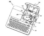
図1は、テープカセット200が収容された従来のラベルプリンタである印刷装置100の斜視図である。図1には、印刷装置100の装置筐体101に設けられた蓋部102が開かれて、カセット収容部110に収容されたテープカセット200が外部に露出した状態が示されている。
FIG. 1 is a perspective view of a
図1に示すように、テープカセット200がカセット収容部110に収容されている状態では、印刷装置100に設けられた軸状の構造物(例えば、サーマルヘッド103やインクリボン巻取り駆動軸104)がテープカセット200に係合している。このため、テープカセット200を取り出す際には、軸状構造がテープカセット200と干渉しないように、軸方向と平行な方向にテープカセット200を持ち上げることが望ましい。
As shown in FIG. 1, in a state where the
しかしながら、従来の印刷装置100では、テープカセット200とカセット収容部110の間には十分な空間が設けられておらず、カセット収容部110には、テープカセット200の切欠き部201に対して対角方向に凹部111が設けられているに過ぎない。このため、テープカセット200を印刷装置100から取り出す際には、図2に示すように、テープカセット200の切欠き部201と、凹部111によって露出したテープカセット200の端部とを支持した状態で、テープカセット200を取り出さざるを得ない。
However, in the
このようにテープカセット200の対角線上の2点を支持してテープカセット200を持ち上げた場合には、テープカセット200が回転して傾きやすい。従って、軸状構造がテープカセット200と干渉してしまうため、テープカセット200を取り出すことが難しい。
When the
以上のような実情を踏まえ、本発明の一側面に係る目的は、テープカセットを取り出しやすい構造を有する印刷装置を提供することである。 Based on the above circumstances, an object of one aspect of the present invention is to provide a printing apparatus having a structure in which a tape cassette can be easily taken out.
本発明の一態様に係る印刷装置は、被印刷媒体を内蔵するカセットを収容する空間であるカセット収容領域が設けられた筐体を備える印刷装置であって、前記カセットは、当該カセット収容領域に収容された状態の前記カセットの厚さ方向に沿って見て、互いに対向配置された第1側面および第2側面と、前記第1側面および前記第2側面に繋がり互いに対向配置された第3側面および第4側面とを有し、前記カセット収容領域は、当該カセット収容領域に収容された状態の前記カセットの厚さ方向に沿って見て、収容されている状態の前記カセットの前記第1側面に隣接し、前記第1側面を含む前記カセットの第1側端領域を支持している状態の第1の指を挿入可能な第1の空間と、収容されている状態の前記カセットの前記第3側面に隣接し、前記第3側面を含む前記カセットの第3側端領域を支持している状態の第3の指を挿入可能な第2の空間と、収容されている状態の前記カセットの前記第2側面に隣接し、前記第2側面を含む前記カセットの第2側端領域を支持している状態の第2の指を挿入可能な開口領域と、を有し、前記開口領域は、テーパー形状の部分と、前記厚さ方向に沿った深さが前記テーパー形状の中央部分において最も深くなる下面部分とを有し、前記カセット収容領域の前記第1の空間および前記開口領域は、前記カセットの前記第1側面のうち前記第1の空間に面した部分と、前記カセットの前記第2側面のうち前記開口領域の前記下面部分に面した部分とが、互いに対向して配置するように設けられている。 The printing apparatus according to one aspect of the present invention is a printing apparatus including a housing provided with a cassette accommodating area which is a space for accommodating a cassette containing a printing medium, and the cassette is provided in the cassette accommodating area. When viewed along the thickness direction of the cassette in the housed state, the first side surface and the second side surface are arranged to face each other, and the third side surface connected to the first side surface and the second side surface and arranged to face each other. And a fourth side surface, the cassette storage area is the first side surface of the cassette in a housed state when viewed along the thickness direction of the cassette in a state of being housed in the cassette house area. A first space into which a first finger can be inserted, which is adjacent to and supports a first side end region of the cassette including the first side surface, and the first space of the cassette in a housed state. A second space in which a third finger can be inserted, which is adjacent to the three side surfaces and supports the third side end region of the cassette including the third side surface, and the cassette in a housed state. The opening area has an opening area in which a second finger can be inserted, which is adjacent to the second side surface and supports a second side end region of the cassette including the second side surface. The first space and the opening region of the cassette accommodating region have a tapered portion and a lower surface portion where the depth along the thickness direction is the deepest in the central portion of the tapered shape. The portion of the first side surface of the cassette facing the first space and the portion of the second side surface of the cassette facing the lower surface portion of the opening region are arranged so as to face each other. It is provided.
上述の態様によれば、テープカセットを取り出しやすい構造を有する印刷装置を提供することができる。 According to the above aspect, it is possible to provide a printing apparatus having a structure in which a tape cassette can be easily taken out.
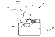
図3は、本発明の一実施形態に係る印刷装置1の斜視図である。印刷装置1は、被印刷媒体に印刷を行うサーマルヘッドを備える印刷装置であり、例えば、長尺状の被印刷媒体Mに、シングルパス方式で印刷を行うラベルプリンタである。
FIG. 3 is a perspective view of the
以降では、インクリボンを使用する熱転写方式のラベルプリンタを例にして説明するが、印刷方式は特に限定されない。例えば、感熱紙を使用する感熱方式であってもよい。被印刷媒体Mは、例えば、接着層を有する基材と、接着層を覆うように剥離可能に基材に貼付された剥離紙と、を有するテープ部材である。被印刷媒体Mは、離型紙なしのテープ部材であってもよい。 Hereinafter, a thermal transfer type label printer using an ink ribbon will be described as an example, but the printing method is not particularly limited. For example, a thermal method using thermal paper may be used. The print medium M is, for example, a tape member having a base material having an adhesive layer and a release paper removably attached to the base material so as to cover the adhesive layer. The print medium M may be a tape member without a paper pattern.
印刷装置1には、図3に示すように、キューブ形状の装置筐体20の上面に、蓋部10と、複数のボタン(ボタン21、ボタン22a、ボタン22b、ボタン22c、ボタン22d)が設けられている。ボタン21は、蓋部10の開閉ボタンである。ボタン22aからボタン22dは、それぞれ電源ボタン、無線通信ボタン、フィードボタン、カットボタンである。また、図示しないが、装置筐体20には、電源コード接続端子、外部機器接続端子等が設けられている。
As shown in FIG. 3, the
蓋部10は、開閉可能に配置されている。蓋部10は、ボタン21が押下されることで開かれて、蓋部10の開放によりカセット収容部30(図5から図7参照)を外部に露出させる。蓋部10には、蓋部10が閉じた状態でもカセット収容部30にテープカセット40(図4参照)が収納されているか否かを目視で確認可能とするために、窓11が形成されている。また、装置筐体20の側面には、排出口20aが形成されている。印刷装置1内で印刷が行われた被印刷媒体Mは、排出口20aから装置外へ排出される。なお、排出口20aは、被印刷媒体Mの印刷面が、印刷装置1が載置された面と直交するように被印刷媒体Mを排出する。
The
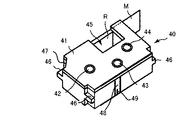
図4は、テープカセット40の斜視図である。テープカセット40は、印刷装置1のカセット収容部30に交換可能に収容される。テープカセット40は、図4に示すように、サーマルヘッド被挿入部45、支持部46、切欠き部47、凹部48が形成された、被印刷媒体MとインクリボンRを収容するカセットケース41を有する。カセットケース41には、テープコア42とインクリボン供給コア43とインクリボン巻取りコア44が設けられている。
FIG. 4 is a perspective view of the
被印刷媒体Mは、カセットケース41内部のテープコア42にロール状に巻かれている。また、熱転写用のインクリボンRは、その先端がインクリボン巻取りコア44に巻きつけられた状態で、カセットケース41内部のインクリボン供給コア43にロール状に巻かれている。さらに、凹部48には解除スイッチ49が設けられている。解除スイッチ49が押下されることで、被印刷媒体Mの搬送を妨げるロック機構が解除され、被印刷媒体Mの搬送が可能となる。
The print medium M is wound around the
図5は、蓋部10が開放された状態における印刷装置1の側面図である。図6及び図7は、蓋部10が開放された状態における印刷装置1の斜視図である。図8及び図9は、蓋部10が開放された状態における印刷装置1の平面図である。図6及び図8には、テープカセット40がカセット収容部30に収容されていない状態が、図7及び図9には、テープカセット40がカセット収容部30に収容されている状態が、示されている。
FIG. 5 is a side view of the
印刷装置1は、図5から図9に示すように、被印刷媒体Mを内蔵したテープカセット40を収容するカセット収容部30を備えている。カセット収容部30は、蓋部10の開放により外部に露出する。
As shown in FIGS. 5 to 9, the
蓋部10は、図6及び図7に示すように、上述した窓11に加えて、凸部12と、押さえ部13と、ピン14を備えて、装置筐体20に設けられた支軸23によって軸支されている。蓋部10は、ボタン21を押下してロック機構が解除されると、被印刷媒体Mの搬送方向と直交している支軸23回りに回転する。これにより、蓋部10の排出口20a側が支軸23上方に向かって移動して、蓋部10が起立して開状態になる。
As shown in FIGS. 6 and 7, the
凸部12は、カセット収容部30に設けられた開口部32に対応する形状を有している。開口部32については後述する。凸部12は、蓋部10が閉じられているときに開口部32に対向するように設けられている。
The
押さえ部13は、蓋部10を閉じる際にカセット収容部30に収容されたテープカセット40の上面を押さえる部材である。押さえ部13は弾性部材を含んでいて、その弾性部材の弾性力によって様々な厚さを有するテープカセット40に過度な圧力が加わらないよう押圧力が調整される。また、押さえ部13は、蓋部10を開くときには、収縮した弾性部材の弾性力によって蓋部10を持ち上げる役割も担っている。
The
ピン14は、蓋部10が閉じられているときに装置筐体20に設けられた開閉検出部24に係合するように、設けられている。ピン14が開閉検出部24に係合することで、開閉検出部24が電気的に蓋部10の閉状態を検出する。印刷装置1は、電源がONになると電動でサーマルヘッド25をプラテンローラ26に押し付けるように動作するが、開閉検出部24が蓋部10の開状態を検出している場合には、サーマルヘッド25をプラテンローラ26に押し付ける動作を行わない。
The
カセット収容部30には、図6から図9に示すように、サーマルヘッド25と、プラテンローラ26が設けられている。サーマルヘッド25は、被印刷媒体Mに印刷を行う印刷ヘッドであり、通電状態が独立に制御される複数の発熱素子25a(図15参照)を有する。また、サーマルヘッド25には、サーミスタ50(図15参照)が埋め込まれている。サーミスタ50は、サーマルヘッド25の温度を測定する測定手段として機能する。プラテンローラ26は、サーマルヘッド25との間に被印刷媒体Mを挟み込みながら被印刷媒体Mを搬送する搬送ローラである。プラテンローラ26は、被印刷媒体Mを排出口20aに向けて搬送方向に搬送する。サーマルヘッド25とプラテンローラ26は、後述する第1の方向に整列して設けられている。
As shown in FIGS. 6 to 9, the
カセット収容部30には、図8に示すように、さらに、インクリボン巻取り駆動軸27と、テープコア係合軸28と、複数の受け部29と、複数のテープ幅検出スイッチ29aと、第1の空間形成部31と、開口部32と、段差33と、突起34と、リブ35と、第2の空間形成部36が設けられている。
As shown in FIG. 8, the
テープカセット40はカセット収容部30のうちの段差33で区画される領域に収容される。例えば、段差33は、下段を構成するカセット収容部30の底面から1〜2cm程度の位置に上段を有している。テープカセット40がカセット収容部30に収納された状態では、テープカセット40の支持部46が受け部29に支持されて、サーマルヘッド25がテープカセット40のサーマルヘッド被挿入部45に挿入されている。また、テープコア係合軸28には、テープカセット40のテープコア42が係合し、インクリボン巻取り駆動軸27には、インクリボン巻取りコア44が係合する。
The
受け部29は、段差33の上段から起立して形成されている。このため、テープカセット40は、テープ幅の広い比較的大きなテープカセットである場合を除き、カセット収容部30のうちの段差33の上段よりも上側の空間に収容される。なお、段差33の上段よりも下側にまでテープカセットが及ぶのは、例えば、そのテープカセットが36mm以上の幅のテープカセットである場合である。また、突起34によって、テープカセット40の凹部48に設けられた解除スイッチ49が押下され、ロック機構が解除される。さらに、リブ35により段差33で区画される領域内でのテープカセット40のガタツキを抑えられる。
The receiving
複数のテープ幅検出スイッチ29aは、テープカセット40の形状に基づいて被印刷媒体Mの幅を検出する検出部である。テープ幅検出スイッチ29aは、複数の受け部29のいずれかの上面に設けられている。テープ幅の異なる複数のテープカセット40は、複数のテープ幅検出スイッチ29aをそれぞれ異なる組み合わせで押下するように構成されている。印刷装置1は、押下されたテープ幅検出スイッチ29aの組み合わせから、テープカセット40の種類を特定し、被印刷媒体Mの幅(テープ幅)を検出する。
The plurality of tape
カセット収容部30が備える第1の空間形成部31と開口部32と第2の空間形成部36は、テープカセット40を印刷装置1から容易に取り出すための構造であり、テープカセット40に指を掛けるための空間をカセット収容部30内に確保するのに資する構造である。より詳細に説明すると、蓋部10が開いているときで、且つ、テープカセット40の第1の側端部、第2の側端部及び第3の側端部がそれぞれ、第1の指、第2の指及び第3の指によって支持された状態でテープカセット40をカセット収容部30から取り出すときに、第1の空間形成部31、開口部32、第2の空間形成部36は、それぞれ次のような特徴を有している。なお、テープカセット40の側端部には、テープカセットの側面に加えて、エッジの部分も含まれる。また、例えば、図4に示される、支持部46、切欠き部47、凹部48等も側端部に含まれる。
The first
第1の空間形成部31は、第1の側端部の少なくとも一部とカセット収容部30との間に第1の指の少なくとも一部が挿入される第1の空間31aを形成するように構成される。より具体的には、第1の空間形成部31は、例えば、図7及び図9に示すように、テープカセット40がカセット収容部30に収容された状態で、カセット収容部30に収容されたテープカセット40の側面40aとカセット収容部30の第1の内壁との間に第1の空間31aを形成する。
The first
ここで、カセット収容部30の第1の内壁とは、カセット収容部30にテープカセット40が収容されているときに、テープカセット40の側面40aと対向するカセット収容部30の面であり、カセット収容部30の第1の空間形成部31を構成する。側面40aは、テープカセット40の第1の側端部であり、第1の方向に向けられたテープカセット40の側面である。第1の方向は、サーマルヘッド25が被印刷媒体Mをプラテンローラ26に押し付ける方向であり、サーマルヘッド25とプラテンローラ26は、第1の方向に沿って整列している。また、側面40aの少なくとも一部とカセット収容部30の第1の内壁との間に形成される第1の空間31aは、テープカセット40を取り出す際にテープカセット40に指を掛けるために指の少なくとも一部が挿入される空間である。第1の空間の幅、即ち、側面40aとカセット収容部30との間の第1の方向の距離は、少なくとも標準的な大人の指が第1間接まで入るような長さがあることが望ましく、1〜2cm程度以上あることが望ましい。一例として、第1の空間の幅は、2.5cmである。また、第1の空間31aは、後述する第2の空間46と連続してL字状に設けられていることが望ましい。
Here, the first inner wall of the
開口部32は、カセット収容部30に収容されたテープカセット40の第2の側端部の少なくとも一部を印刷装置1の外部に露出させることによって、露出された第2の側端部の少なくとも一部を第2の指によって支持するための開口部である。より具体的には、開口部32は、例えば、図7及び図9に示すように、カセット収容部30に収容されたテープカセット40の側面40bを蓋部10が開いているときに外部に露出させる。
The
ここで、側面40bは、テープカセット40の第2の側端部であり、第1の方向とは異なる方向(以降、第2の方向と記す。)に向けたられたテープカセット40の側面である。第2の方向は、第1の方向と反対の方向であることが望ましい。開口部32は、蓋部10の開状態において、テープカセット40bの第2の方向側に装置外につながった開放空間を形成する。この開放空間も、第1の空間と同様に、テープカセット40を取り出す際にテープカセット40に指を掛けるために指の少なくとも一部が挿入される空間である。
Here, the
一例として、開口部32は、図5に示すテーパー形状を呈している部分を除いて2〜4cm程度の深さを有し、開口部32の平坦な下面は、カセット収容部30の底面から1〜2cm程度の高さを有する。比較的狭いテープ幅(例えば、9mm以下のテープ幅)のテープカセット40が収容されている場合には、開口部32の下面は、テープカセット40の下面よりも低い位置に位置する。このため、開口部32から挿入した指を、テープカセット40の下面又は下面と側面40bとの間のエッジ部分に掛けて、テープカセット40を支えることができる。テープ幅が最も広いテープ幅(例えば、46mm幅)のテープカセット40が収容されている場合であっても、開口部32の下面はそのテープカセット40の中心よりも下側に位置する。このため、テープカセット40の中心よりも下側に当てた指によってテープカセット40の安定した支持が可能である。
As an example, the
第2の空間形成部36は、第3の側端部の少なくとも一部とカセット収容部30との間に第3の指の少なくとも一部が挿入される第2の空間36aを形成する。より具体的には、カセット収容部30は、例えば、図7及び図9に示すように、テープカセット40の側面40cとカセット収容部30の第2の内壁との間に第2の空間36aを形成するようにカセット収容部30を収容する。つまり、カセット収容部30には、第2の空間36aを形成するように、テープカセット40を位置決めする構造物(サーマルヘッド25、インクリボン巻取り駆動軸27、受け部29など)が設けられている。
The second
ここで、カセット収容部30の第2の内壁とは、カセット収容部30にテープカセット40が収容されているときに、テープカセット40の側面40cと対向するカセット収容部30の面であり、カセット収容部30の第2の空間形成部36を構成する。側面40cは、テープカセット40の第3の側端部であり、第1の方向と第2の方向の両方と異なる方向(以降、第3の方向と記す。)に向けられたテープカセット40の側面である。第3の方向は、被印刷媒体Mの搬送方向と反対の方向であることが望ましく、第1の方向及び第2の方向と直交する方向であることが更に望ましい。即ち、排出口20aは、被印刷媒体Mを、テープカセット40の第1の側端部、第2の側端部、及び第3の側端部の全てと異なる第4の側端部側から印刷装置1外部に排出することが望ましい。また、側面40cとカセット収容部30の間に形成される第2の空間は、テープカセット40を取り出す際にテープカセット40に指を掛けるために指の少なくとも一部が挿入される空間である。第2の空間の幅、即ち、側面40cとカセット収容部30の間の第3の方向の距離は、少なくとも標準的な大人の指が第1間接まで入るような長さがあることが望ましく、1〜2cm程度以上あることが望ましい。第2の空間の幅は、一例として、1.5cmである。この場合、2cmの幅の第1の空間と1.5cmの幅の第2の空間により形成されるL字形状の空間は、コーナー部分で3cm弱程度の幅を有する。
Here, the second inner wall of the
図10及び図11は、印刷装置1からテープカセット40を取り出す様子を示した図である。印刷装置1では、カセット収容部30内において、テープカセット40の周囲の3方向に空間が形成されている。このため、図10及び図11に示すように、印刷装置1の利用者はテープカセット40を取り出す際に3方向からテープカセット40に指を掛けることができる。これにより、テープカセット40を傾けることなく持ち上げることができるため、テープカセット40を印刷装置1から容易に取り出すことができる。
10 and 11 are views showing how the
また、印刷装置1では、第1の方向と第2の方向が反対の方向になるように、第1の空間形成部31と開口部32が設けられている。このため、図10及び図11に示すように、印刷装置1の利用者はテープカセット40の互いに反対を向いた2つの側面(側面40a、側面40b)に指を掛けて、テープカセット40をしっかりと挟み込むことができる。これにより、テープカセット40を安定して持ち上げることができるため、テープカセット40を印刷装置1からさらに容易に取り出すことができる。
Further, in the
また、印刷装置1では、図7及び図9に示されるように、第1の空間31aは、第2の空間36aと連続してL字状に設けられている。別の言い方をすると、第1の空間31aと第2の空間36aはL字形状を有し、それぞれが空間的に隣接して連続している。このため、開口部32により形成された空間に親指を入れてテープカセット40に親指を掛けたユーザーが、第1の空間31aと第2の空間36aによって形成されるL字型の連続空間に残りの指を自由に配置することができる。このような指の配置の自由度の高さは、使い勝手が手の大きさに左右されにくいなどのメリットがあり、多くのユーザーにとってテープカセット40を持ち上げやすく取り出しやすい構造を提供することができる。特に連続空間を構成するそれぞれの空間に1本以上指を掛けることで、計3本以上の指で3つ以上の異なる方向からテープカセット40を支えることができる。このため、テープカセット40を安定した姿勢で取り出すことができる。
Further, in the
また、印刷装置1では、カセット収容部30から第3の方向の位置に支軸23が設けられている。第1の方向と第2の方向が反対方向である場合には、図10及び図11に示すように、印刷装置1の利用者は、第1の方向に向けられた側面40aと第2の方向に向けられた側面40bの一方に親指を掛け他方向に中指又は薬指を掛けてテープカセット40を挟み込み、さらに、第3の方向に向けられた側面40cに人差し指を掛けテープカセット40を持ち上げることが想定される。従って、テープカセット40を取り出す際には、印刷装置1の利用者は、第3の方向とは反対方向に位置することが想定される。支軸23が第3の方向に位置することで、開いた蓋部10が支軸23上に起立することになる。このような利用者と蓋部10の位置関係であれば、テープカセット40を取り出す際に蓋部10が邪魔にならないため、テープカセット40を印刷装置1からさらに容易に取り出すことができる。
Further, in the
さらに、印刷装置1では、第3の方向が搬送方向と反対の方向であり、テープカセット40から見て搬送方向と反対の方向に指を入れるための空間が設けられている。一般にテープカセット40の搬送方向側には被印刷媒体Mのカット機構など特定の構造物が配置されるのに対して、搬送方向と反対側のスペースは比較的自由に利用することができる。従って、第3の方向を搬送方向と反対の方向にすることで、特定の構造物を配置するためのスペースが少なくなる、装置筐体20が大きくなってしまう、等の事態を避けることができる。
Further, in the
さらに、印刷装置1では、蓋部10の凸部12は、開口部32に対応する形状を有し、且つ、蓋部10が閉じられているときに開口部32に対向するように設けられている。このため、蓋部10が閉じられているときに凸部12が占める空間をテープカセット40の第2の側面40bを露出させる空間として利用することができる。これにより、印刷装置1を大型化することなくテープカセット40を取り出す際に指を掛ける空間を設けることができる。また、蓋部10が閉じているときには側面40bが露出していないため、ゴミなどが印刷中に印刷装置1内部に入ってしまうことを抑制することができる。
Further, in the
さらに、印刷装置1では、テープカセットは、その種類によらず、被印刷媒体Mの幅方向の中心が一定の位置となるように収容される。このため、開口部32の高さをこの一定の位置程度またはそれ以下とすることで、印刷装置1は、テープカセットの種類によらず、カセット収容部30に収容したテープカセットの側面を露出させることができる。
Further, in the
図12から図14は、それぞれテープ幅6mmのテープカセット60、テープ幅24mmのテープカセット70、テープ幅46mmのテープカセット80が収容された印刷装置1の斜視図である。一般に、テープ幅6mm程度の幅の狭いテープからテープ幅46mm程度の幅の広いテープにまで対応可能な印刷装置では、幅の狭いテープが内蔵されたテープカセットをカセット収容部に挿入する或いはカセット収容部から取り出す場合には、印刷装置内部の深い位置にまで指を挿入することが要求される。印刷装置1では、図12から図14に示すように、テープカセットの種類によらず、開口部32からテープカセットの側面(側面60b、側面70b、側面80b)が露出されるため、テープカセットの種類によらず、テープカセットを印刷装置1から容易に取り出すことができる。
12 to 14 are perspective views of the
以上では、テープカセット40の取り出しやすさを中心に説明したが、印刷装置1によれば、テープカセット40をカセット収容部30に容易に収容することもできる。印刷装置1では、テープカセット40を指で支えた状態でカセット収容部30の深い位置にまでテープカセット40の姿勢を変えずに移動させることができる。このため、テープカセット40がカセット収容部30に設けられた受け部29に完全に支持されるまでテープカセット40を持ち続けることができる。このため、利用者は、テープカセット40を容易に且つ確実にカセット収容部30に収容することができる。
In the above description, the ease of taking out the
図15は、印刷装置1の制御ブロック図である。印刷装置1は、上述した構成に加えて、制御部2、通信インターフェース3、ROM(Read Only Memory)4、RAM(Random Access Memory)5、ヘッド駆動回路51、搬送用モータ駆動回路52、ステッピングモータ53、カッターモータ駆動回路54、カッターモータ55、フルカット機構56、ハーフカット機構57を備える。なお、制御部2、ROM4、及びRAM5は、印刷装置1のコンピュータを構成する。
FIG. 15 is a control block diagram of the
制御部2は、例えばCPU(Central Processing Unit)などのプロセッサ2aを含む。制御部2は、ROM4に記憶されているプログラムをRAM5に展開し実行することで、印刷装置1の各部の動作を制御する。通信インターフェース3は、有線又は無線により外部装置との間でデータを授受する。
The control unit 2 includes a processor 2a such as a CPU (Central Processing Unit). The control unit 2 controls the operation of each unit of the
ROM4は、被印刷媒体Mに印刷を行う印刷プログラム、印刷プログラムの実行に必要な各種データ(例えば、フォント等)を記憶する。なお、ROM4は、制御部2によって読取り可能なプログラムが記憶された記憶媒体としても機能する。 The ROM 4 stores a print program for printing on the print medium M and various data (for example, fonts and the like) necessary for executing the print program. The ROM 4 also functions as a storage medium in which a program readable by the control unit 2 is stored.
RAM5は、印刷についての情報(以降、印刷情報と記す)を記憶する入力データメモリとして機能する。また、RAM5は、印刷情報に基づいて生成される、被印刷媒体に形成すべき印刷内容のパターンを示すデータ(以降、印刷データと記す)を記憶する印刷データメモリとしても機能する。 The RAM 5 functions as an input data memory for storing information about printing (hereinafter referred to as print information). The RAM 5 also functions as a print data memory for storing data (hereinafter, referred to as print data) indicating a pattern of print contents to be formed on a print medium, which is generated based on print information.
ヘッド駆動回路51は、印刷データとストローブ信号に基づいて発熱素子25aへの通電を行う。サーマルヘッド25は、主走査方向に配列された複数の発熱素子25aを有する印刷ヘッドである。サーマルヘッド25は、制御部2から送出されたストローブ信号がONである期間(即ち、通電期間)に印刷データに応じて発熱素子25aをヘッド駆動回路51が選択的に通電することで、発熱素子25aでインクリボンRを加熱して熱転写により被印刷媒体Mに一ラインずつ印刷を行う。
The
搬送用モータ駆動回路52は、ステッピングモータ53を駆動する。ステッピングモータ53は、プラテンローラ26を駆動する。プラテンローラ26は、ステッピングモータ53の動力によって回転し、被印刷媒体Mの長手方向(副走査方向、搬送方向)に被印刷媒体Mを搬送する。
The transport
カッターモータ駆動回路54は、カッターモータ55を駆動する。フルカット機構56及びハーフカット機構57は、カッターモータ55の動力によって動作し、被印刷媒体Mをフルカット又はハーフカットする。フルカットとは、被印刷媒体Mの基材を剥離紙とともに幅方向に沿って切断する動作のことであり、ハーフカットは、基材のみを幅方向に沿って切断する動作のことである。カッターモータ駆動回路54は、例えば、ボタン22dが押下されるとカッターモータ55を駆動してフルカット機構56に被印刷媒体Mをフルカットさせてもよい。
The cutter
上述した実施形態は、発明の理解を容易にするために具体例を示したものであり、本発明は上述した実施形態に限定されるものではない。印刷装置は、特許請求の範囲の記載を逸脱しない範囲において、さまざまな変形、変更が可能である。 The above-described embodiment shows a specific example for facilitating the understanding of the invention, and the present invention is not limited to the above-mentioned embodiment. The printing apparatus can be modified and changed in various ways without departing from the description of the claims.
上述した実施形態では、第3の方向が搬送方向と反対の方向である例を示したが、第3の方向は搬送方向と直交する方向であってもよく、第1の方向又は第2の方向が搬送方向と同じ方向であってもよい。上述した実施形態では、印刷装置1は印刷データを外部装置から受信して印刷を行うが、印刷装置1は印刷データを入力するための入力部や表示部を備えてもよい。
In the above-described embodiment, an example is shown in which the third direction is opposite to the transport direction, but the third direction may be a direction orthogonal to the transport direction, and the first direction or the second direction may be used. The direction may be the same as the transport direction. In the above-described embodiment, the
以下、本願の出願当初の特許請求の範囲に記載された発明を付記する。
[付記1]
印刷装置であって、
被印刷媒体を内蔵したテープカセットを収容するカセット収容部と、
開放により前記カセット収容部を外部に露出させる蓋部と、を備え、
前記カセット収容部は、
前記蓋部が開いているとき、前記テープカセットの第1の側端部、第2の側端部及び第3の側端部がそれぞれ、第1の指、第2の指及び第3の指によって支持された状態で前記テープカセットを前記カセット収容部から取り出す際に、
前記第1の側端部の少なくとも一部と前記カセット収容部との間に前記第1の指の少なくとも一部が挿入される第1の空間を形成する第1の空間形成部と、
前記カセット収容部に収容された前記テープカセットの前記第2の側端部の少なくとも一部を前記印刷装置の外部に露出させることによって、前記露出された前記第2の側端部の少なくとも一部を前記第2の指によって支持するための開口部と、
前記第3の側端部の少なくとも一部と前記カセット収容部との間に前記第3の指の少なくとも一部が挿入される第2の空間を形成する第2の空間形成部と、
を備える、
ことを特徴とする印刷装置。
Hereinafter, the inventions described in the claims at the time of filing the application of the present application will be added.
[Appendix 1]
It ’s a printing device,
A cassette storage unit that houses a tape cassette containing a print medium,
A lid portion for exposing the cassette accommodating portion to the outside by opening is provided.
The cassette accommodating part
When the lid is open, the first side end, the second side end and the third side end of the tape cassette are the first finger, the second finger and the third finger, respectively. When removing the tape cassette from the cassette housing while being supported by
A first space forming portion forming a first space into which at least a part of the first finger is inserted between at least a part of the first side end portion and the cassette accommodating portion.
By exposing at least a part of the second side end of the tape cassette housed in the cassette housing to the outside of the printing apparatus, at least a part of the exposed second side end. With an opening for supporting the second finger,
A second space forming portion forming a second space into which at least a part of the third finger is inserted between at least a part of the third side end portion and the cassette accommodating portion.
To prepare
A printing device characterized by that.
[付記2]
付記1に記載の印刷装置において、
前記蓋部は、前記蓋部が閉じられているときに前記開口部に対向するように設けられた、前記開口部に対応する形状を有する凸部を備える
ことを特徴とする印刷装置。
[Appendix 2]
In the printing apparatus described in
The printing apparatus is characterized in that the lid portion includes a convex portion having a shape corresponding to the opening portion, which is provided so as to face the opening portion when the lid portion is closed.
[付記3]
付記1又は付記2に記載の印刷装置において、
前記第1の空間は、前記第2の空間と連続してL字状に設けられている
ことを特徴とする印刷装置。
[Appendix 3]
In the printing apparatus described in
A printing apparatus characterized in that the first space is continuously provided in an L shape with the second space.
[付記4]
付記1から付記3のいずれかに記載の印刷装置において、さらに、
前記被印刷媒体に印刷を行う印刷ヘッドと、
前記印刷ヘッドとの間に前記被印刷媒体を挟み込みながら前記被印刷媒体を搬送する搬送ローラと、
前記被印刷媒体を、前記テープカセットの前記第1の側端部、前記第2の側端部、及び前記第3の側端部の全てと異なる前記第4の側端部側から前記印刷装置外部に排出する排出口と、
を備えることを特徴とする印刷装置。
[Appendix 4]
In the printing apparatus according to any one of
A print head that prints on the print medium,
A transport roller that conveys the print medium while sandwiching the print medium between the print head and the print head.
The printing device is printed on the printing medium from the fourth side end side, which is different from all of the first side end portion, the second side end portion, and the third side end portion of the tape cassette. Outlet to discharge to the outside and
A printing apparatus comprising.
[付記5]
付記4に記載の印刷装置において、
前記排出口は、前記被印刷媒体の印刷面が、前記印刷装置が載置された面と直交するように前記被印刷媒体を排出することを特徴とする印刷装置。
[Appendix 5]
In the printing apparatus described in Appendix 4,
The ejection port is a printing apparatus characterized in that the printing medium is ejected so that the printing surface of the printing medium is orthogonal to the surface on which the printing apparatus is placed.
[付記6]
付記1乃至付記5のいずれかに記載の印刷装置において、
前記蓋部は、前記蓋部が閉まる際に前記カセット収容部に収容された前記テープカセットの上面を押さえる押さえ部を有することを特徴とする印刷装置。
[Appendix 6]
In the printing apparatus according to any one of
The printing apparatus, characterized in that the lid portion has a pressing portion that presses the upper surface of the tape cassette housed in the cassette accommodating portion when the lid portion is closed.
1、100・・・印刷装置、2・・・制御部、2a・・・プロセッサ、3・・・通信インターフェース、4・・・ROM、5・・・RAM、10、102・・・蓋部、11・・・窓、12・・・凸部、13・・・押さえ部、14・・・ピン、20、101・・・装置筐体、20a・・・排出口、21、22a、22b、22c、22d・・・ボタン、23・・・支軸、24・・・開閉検出部、25、103・・・サーマルヘッド、25a・・・発熱素子、26・・・プラテンローラ、27、104・・・インクリボン巻取り駆動軸、28・・・テープコア係合軸、29・・・受け部、29a・・・テープ幅検出スイッチ、30、110・・・カセット収容部、31・・・第1の空間形成部、31a・・・第1の空間、32・・・開口部、33・・・段差、34・・・突起、35・・・リブ、36・・・第2の空間形成部、36a・・・第2の空間、40、60、70、80、200・・・テープカセット、40a、40b、40c、60b、70b、80b・・・側面、41・・・カセットケース、42・・・テープコア、43・・・インクリボン供給コア、44・・・インクリボン巻取りコア、45・・・サーマルヘッド被挿入部、46・・・支持部、47、201・・・切欠き部、48、111・・・凹部、49・・・解除スイッチ、50・・・サーミスタ、51・・・ヘッド駆動回路、52・・・搬送用モータ駆動回路、53・・・ステッピングモータ、54・・・カッターモータ駆動回路、55・・・カッターモータ、56・・・フルカット機構、57・・・ハーフカット機構、M・・・被印刷媒体、R・・・インクリボン 1, 100 ... printing device, 2 ... control unit, 2a ... processor, 3 ... communication interface, 4 ... ROM, 5 ... RAM, 10, 102 ... lid, 11 ... Window, 12 ... Convex part, 13 ... Holding part, 14 ... Pin, 20, 101 ... Device housing, 20a ... Discharge port, 21, 22a, 22b, 22c , 22d ... Button, 23 ... Support shaft, 24 ... Open / close detection unit, 25, 103 ... Thermal head, 25a ... Heat generation element, 26 ... Platen roller, 27, 104 ... -Ink ribbon winding drive shaft, 28 ... Tape core engaging shaft, 29 ... Receiving part, 29a ... Tape width detection switch, 30, 110 ... Cassette accommodating part, 31 ... First Space forming part, 31a ... First space, 32 ... Opening, 33 ... Step, 34 ... Protrusion, 35 ... Rib, 36 ... Second space forming part, 36a Second space, 40, 60, 70, 80, 200 ... Tape cassette, 40a, 40b, 40c, 60b, 70b, 80b ... Side surface, 41 ... Cassette case, 42 ... Tape core, 43 ... Ink ribbon supply core, 44 ... Ink ribbon winding core, 45 ... Thermal head insertion part, 46 ... Support part, 47, 201 ... Notch part, 48, 111 ... recess, 49 ... release switch, 50 ... thermista, 51 ... head drive circuit, 52 ... transport motor drive circuit, 53 ... stepping motor, 54 ... cutter motor Drive circuit, 55 ... Cutter motor, 56 ... Full cut mechanism, 57 ... Half cut mechanism, M ... Printed medium, R ... Ink ribbon
Claims (13)
前記カセットは、当該カセット収容領域に収容された状態の前記カセットの厚さ方向に沿って見て、互いに対向配置された第1側面および第2側面と、前記第1側面および前記第2側面に繋がり互いに対向配置された第3側面および第4側面とを有し、
前記カセット収容領域は、当該カセット収容領域に収容された状態の前記カセットの厚さ方向に沿って見て、収容されている状態の前記カセットの前記第1側面に隣接し、前記第1側面を含む前記カセットの第1側端領域を支持している状態の第1の指を挿入可能な第1の空間と、収容されている状態の前記カセットの前記第3側面に隣接し、前記第3側面を含む前記カセットの第3側端領域を支持している状態の第3の指を挿入可能な第2の空間と、収容されている状態の前記カセットの前記第2側面に隣接し、前記第2側面を含む前記カセットの第2側端領域を支持している状態の第2の指を挿入可能な開口領域と、を有し、
前記開口領域は、テーパー形状の部分と、前記厚さ方向に沿った深さが前記テーパー形状の中央部分において最も深くなる下面部分とを有し、
前記カセット収容領域の前記第1の空間および前記開口領域は、前記カセットの前記第1側面のうち前記第1の空間に面した部分と、前記カセットの前記第2側面のうち前記開口領域の前記下面部分に面した部分とが、互いに対向して配置するように設けられている、
印刷装置。 A printing apparatus including a housing provided with a cassette accommodating area, which is a space for accommodating a cassette containing a printing medium.
The cassette is viewed on the first side surface and the second side surface which are arranged to face each other, and the first side surface and the second side surface when viewed along the thickness direction of the cassette in a state of being housed in the cassette storage area. It has a third side surface and a fourth side surface that are connected and arranged so as to face each other.
The cassette receiving area, when viewed along the thickness direction of the cassette in a state of being accommodated in the cassette receiving area, adjacent to the first side surface of the cassette in a state of being accommodated, said first side surface A first space into which a first finger can be inserted while supporting a first side end region of the cassette including the cassette, and a third side surface of the cassette in a housed state adjacent to the third side surface . A second space into which a third finger can be inserted while supporting a third side end region of the cassette including a side surface, and adjacent to the second side surface of the cassette in a housed state, said It has an opening area into which a second finger can be inserted in a state of supporting the second side end region of the cassette including the second side surface.
The opening region has a tapered portion and a lower surface portion where the depth along the thickness direction is the deepest in the central portion of the tapered shape.
The first space and the opening area of the cassette accommodating area are a portion of the first side surface of the cassette facing the first space and the opening area of the second side surface of the cassette. The portion facing the lower surface portion is provided so as to be arranged so as to face each other.
Printing device.
前記第2の空間は、前記厚さ方向に沿って見て、前記第3側面の全長にわたって当該第3側面に面するように設けられている、
印刷装置。 In the printing apparatus according to claim 1,
The second space, the look along the thickness direction, are provided so as to face to the third side surface over the entire length of said third side,
Printing device.
前記第1の空間、前記第2の空間、又は、前記開口領域は、前記厚さ方向に沿って見て、前記第1側面、前記第3側面、又は、前記第2側面の各法線方向に沿う長さが、前記第1側面、前記第3側面、又は、前記第2側面の全長にわたって略同一となるように設けられている、
印刷装置。 In the printing apparatus according to claim 1 or 2.
It said first space, said second space, or, the open region, the look along the thickness direction, the first side surface, the third side surface, or, the normal direction of the second side The length along the first side surface, the third side surface, or the second side surface is provided so as to be substantially the same over the entire length of the first side surface, the third side surface, or the second side surface.
Printing device.
前記カセットは、前記厚さ方向に沿って見て、前記第1側面および前記第2側面に各対応する部分を2つの長辺とし、前記第3側面および前記第4側面に各対応する部分を2つの短辺とする、略矩形状であり、
前記第1の空間および前記開口領域は、前記2つの長辺に沿うように設けられている、
印刷装置。 In the printing apparatus according to any one of claims 1 to 3.
The cassette, the viewed along the thickness direction, the the first side surface and the second side surface of each corresponding portions as two long sides, portions each corresponding to the third side and the fourth side surface It has a substantially rectangular shape with two short sides.
The first space and the opening area are provided along the two long sides.
Printing device.
前記開口領域は、前記カセットの前記第2側面の前記厚さ方向の中央の領域と、前記第2側面の前記厚さ方向の前記中央の領域から上側の領域と、を外部に露出させる形状に形成されている、
印刷装置。 In the printing apparatus according to any one of claims 1 to 4.
The opening region, a central region of the thickness direction of the second side surface of the cassette, into a shape to expose the an upper area from the central region of the thickness direction of the second side surface to the outside Is formed,
Printing device.
前記カセット収容領域は、前記カセットの厚さが互いに異なる複数の種類の前記カセットの何れも収容可能であり、
前記複数の種類の前記カセットの何れも、前記カセット収容領域に、前記厚さ方向の中央が一定の位置となるように収容される、
印刷装置。 In the printing apparatus according to any one of claims 1 to 5.
The cassette accommodating area can accommodate any of a plurality of types of the cassettes having different thicknesses of the cassettes.
Any of the plurality of kinds of the cassette, the cassette receiving area, said thickness direction center is accommodated such that the fixed position,
Printing device.
前記厚さ方向に沿って見て、
前記第1の空間の前記第1側面の法線方向に沿う長さが、2cm又はそれ以上であり、
前記第2の空間の前記第3側面の法線方向に沿う長さが、1cm又はそれ以上である、
印刷装置。 In the printing apparatus according to any one of claims 1 to 6.
The look along the thickness direction,
The length of the first space along the normal direction of the first side surface is 2 cm or more.
The length of the second space along the normal direction of the third side surface is 1 cm or more.
Printing device.
前記カセットは、前記カセット収容領域に収容されている状態において上側となる上面と、下側となる下面と、を有し、
前記カセット収容領域の前記第1の空間、前記第2の空間、及び、前記開口領域の少なくとも何れかは、前記カセット収容領域に収容された前記カセットが取り出される場合に、前記少なくとも何れかの空間又は領域に挿入された指によって、前記カセットの前記下面の一部を支持することを可能とする大きさに形成されている、
印刷装置。 In the printing apparatus according to any one of claims 1 to 7.
The cassette has an upper surface that is an upper side and a lower surface that is a lower side when the cassette is housed in the cassette storage area.
At least one of the first space, the second space, and the opening area of the cassette storage area is at least one of the spaces when the cassette housed in the cassette storage area is taken out. Alternatively, the size is formed so that a part of the lower surface of the cassette can be supported by a finger inserted into the region.
Printing device.
前記カセット収容領域を外部に露出させる開状態、又は、前記カセット収容領域を外部に露出させない閉状態、に設定される蓋部材を備え、
前記蓋部材は、前記開口領域の前記テーパー形状の部分と前記下面部分とに対向する形状に形成された凸部を備え、
前記蓋部材は、前記閉状態に設定されている場合に前記凸部が前記開口領域の前記テーパー形状の部分と前記下面部分とに嵌って、前記開口領域を閉じる、
印刷装置。 In the printing apparatus according to any one of claims 1 to 8, further
The lid member is provided with a lid member set to an open state in which the cassette accommodating area is exposed to the outside or a closed state in which the cassette accommodating area is not exposed to the outside.
The lid member includes a convex portion formed in a shape facing the tapered portion and the lower surface portion of the opening region.
When the lid member is set to the closed state, the convex portion fits into the tapered portion and the lower surface portion of the opening region to close the opening region.
Printing device.
前記蓋部材は、前記印刷装置に設けられている支持軸を介して回動することにより、前記開状態又は前記閉状態とされ、
前記支持軸は、前記印刷装置における、前記第2の空間より外側となる位置に設けられている、
印刷装置。 In the printing apparatus according to claim 9.
The lid member is brought into the open state or the closed state by rotating via a support shaft provided in the printing device.
The support shaft is provided at a position outside the second space in the printing apparatus.
Printing device.
前記第1の空間、前記第2の空間、および、前記開口領域は、前記カセットの前記第1側面が一つの手の第1の指で支持され、前記第2側面が前記手の、前記第1の指と異なる第2の指で支持され、前記第3側面が前記手の、前記第1及び第2の指と異なる第3の指で支持されている状態で、前記カセットを、前記カセット収容領域から取り出し可能か、又は、前記カセット収容領域に収容可能であるように、設けられている、
印刷装置。 In the printing apparatus according to any one of claims 1 to 10.
In the first space, the second space, and the opening region, the first side surface of the cassette is supported by the first finger of one hand, and the second side surface is the second side surface of the hand. The cassette is supported by a second finger different from the first finger and the third side surface is supported by a third finger different from the first and second fingers of the hand. It is provided so that it can be taken out of the storage area or can be stored in the cassette storage area.
Printing device.
前記被印刷媒体に印刷を行う印刷ヘッドと、
前記印刷ヘッドとの間に前記被印刷媒体を挟み込みながら、前記被印刷媒体を、前記第1側面に沿った方向に搬送する搬送ローラと、を備え、
前記カセット収容領域の前記第1の空間は、前記カセットの前記第1側面に隣接する領域のうち、前記搬送ローラが設けられた部分を除いて設けられている、
印刷装置。 In the printing apparatus according to any one of claims 1 to 11, further
A print head that prints on the print medium,
A transport roller for transporting the print medium in a direction along the first side surface while sandwiching the print medium between the print head and the print head is provided.
The first space of the cassette accommodating area is provided except for a portion of the area adjacent to the first side surface of the cassette, in which the transport roller is provided.
Printing apparatus.
前記被印刷媒体に印刷を行う印刷ヘッドと、
前記印刷ヘッドとの間に前記被印刷媒体を挟み込みながら、前記被印刷媒体を、前記第1側面に沿った方向に搬送する搬送ローラと、
前記印刷ヘッドにより前記印刷が行われた前記被印刷媒体を外部に排出する排出口と、を備え、
前記カセット収容領域の前記第2の空間は、前記印刷装置における、前記排出口が設けられている側に対して反対側となる位置に設けられている、
印刷装置。 The printing apparatus according to any one of claims 1 to 11, further
A print head that prints on the print medium,
A transport roller that conveys the print medium in a direction along the first side surface while sandwiching the print medium between the print head and the print head.
A discharge port for discharging the printable medium on which the printing was performed by the print head to the outside is provided.
The second space of the cassette accommodating area is provided at a position opposite to the side where the discharge port is provided in the printing apparatus.
Printing device.
Priority Applications (2)
| Application Number | Priority Date | Filing Date | Title |
|---|---|---|---|
| JP2016205536A JP6880643B2 (en) | 2016-10-19 | 2016-10-19 | Printing equipment |
| CN201710975808.5A CN107962875B (en) | 2016-10-19 | 2017-10-19 | Printing equipment |
Applications Claiming Priority (1)
| Application Number | Priority Date | Filing Date | Title |
|---|---|---|---|
| JP2016205536A JP6880643B2 (en) | 2016-10-19 | 2016-10-19 | Printing equipment |
Publications (3)
| Publication Number | Publication Date |
|---|---|
| JP2018065298A JP2018065298A (en) | 2018-04-26 |
| JP2018065298A5 JP2018065298A5 (en) | 2019-07-25 |
| JP6880643B2 true JP6880643B2 (en) | 2021-06-02 |
Family
ID=61997678
Family Applications (1)
| Application Number | Title | Priority Date | Filing Date |
|---|---|---|---|
| JP2016205536A Active JP6880643B2 (en) | 2016-10-19 | 2016-10-19 | Printing equipment |
Country Status (2)
| Country | Link |
|---|---|
| JP (1) | JP6880643B2 (en) |
| CN (1) | CN107962875B (en) |
Families Citing this family (4)
| Publication number | Priority date | Publication date | Assignee | Title |
|---|---|---|---|---|
| US20210380632A1 (en) | 2018-03-29 | 2021-12-09 | Kaneka Corporation | Method for producing long-chain peptide |
| JP7247647B2 (en) * | 2019-02-26 | 2023-03-29 | ブラザー工業株式会社 | printer |
| JP7306102B2 (en) * | 2019-06-24 | 2023-07-11 | ブラザー工業株式会社 | printer |
| JP7293983B2 (en) | 2019-08-26 | 2023-06-20 | カシオ計算機株式会社 | PRINTING DEVICE, CONTROL METHOD, AND PROGRAM |
Family Cites Families (19)
| Publication number | Priority date | Publication date | Assignee | Title |
|---|---|---|---|---|
| JP2995314B2 (en) * | 1992-10-15 | 1999-12-27 | カシオ計算機株式会社 | Tape cassette and printing device |
| EP0593821B1 (en) * | 1992-10-22 | 1997-01-22 | Agfa-Gevaert N.V. | Dye ribbon package for reloading the reloadable cassette of a thermal printer |
| JPH11105351A (en) * | 1997-10-02 | 1999-04-20 | Casio Comput Co Ltd | Printing tape and cassette with the same housed therein |
| WO2002032682A1 (en) * | 2000-10-19 | 2002-04-25 | Brother Kogyo Kabushiki Kaisha | Tape cassette and tape unit |
| JP2005059389A (en) * | 2003-08-12 | 2005-03-10 | Seiko Epson Corp | Tape feeding mechanism and tape printing device having the same |
| JP4556827B2 (en) * | 2004-10-13 | 2010-10-06 | カシオ計算機株式会社 | Printing device |
| JP2006192777A (en) * | 2005-01-14 | 2006-07-27 | Seiko Epson Corp | Tape printer |
| JP3807449B2 (en) * | 2005-09-13 | 2006-08-09 | カシオ計算機株式会社 | Tape printing apparatus and tape cassette for printing |
| JP4645394B2 (en) * | 2005-09-29 | 2011-03-09 | カシオ計算機株式会社 | Printing device |
| JP2009014455A (en) * | 2007-07-03 | 2009-01-22 | Ishida Co Ltd | Weighing device |
| JP5289881B2 (en) * | 2008-09-29 | 2013-09-11 | 株式会社キングジム | Tape printer |
| JP5228809B2 (en) * | 2008-11-04 | 2013-07-03 | セイコーエプソン株式会社 | Ink ribbon cartridge |
| JP4962523B2 (en) * | 2009-03-31 | 2012-06-27 | ブラザー工業株式会社 | Tape cassette |
| CN102361758B (en) * | 2009-03-31 | 2015-11-25 | 兄弟工业株式会社 | Tape drum |
| EP2415612B1 (en) * | 2009-03-31 | 2019-09-25 | Brother Kogyo Kabushiki Kaisha | Tape cassette |
| CN104802537A (en) * | 2009-04-28 | 2015-07-29 | 迪默公司 | Cassette for use in a label printer |
| JP5454361B2 (en) * | 2010-05-31 | 2014-03-26 | ブラザー工業株式会社 | Printing device |
| JP5857677B2 (en) * | 2011-11-25 | 2016-02-10 | ブラザー工業株式会社 | Tape printer |
| CN203004554U (en) * | 2013-01-09 | 2013-06-19 | 珠海纳思达企业管理有限公司 | Ribbon cartridge for label printing apparatus |
-
2016
- 2016-10-19 JP JP2016205536A patent/JP6880643B2/en active Active
-
2017
- 2017-10-19 CN CN201710975808.5A patent/CN107962875B/en active Active
Also Published As
| Publication number | Publication date |
|---|---|
| CN107962875A (en) | 2018-04-27 |
| JP2018065298A (en) | 2018-04-26 |
| CN107962875B (en) | 2019-09-03 |
Similar Documents
| Publication | Publication Date | Title |
|---|---|---|
| JP6880643B2 (en) | Printing equipment | |
| EP2416966B1 (en) | CASSETTE FOR USE IN A LABEL PRINTER, label printer and combination thereof | |
| ES2898064T3 (en) | Printer for printing printing objects | |
| JP2005193468A (en) | Roll sheet holder and tape printer | |
| JP7130948B2 (en) | ELECTRONIC DEVICE, PRINTING SUPPORT METHOD AND PROGRAM | |
| JP3982378B2 (en) | Tape printer, program, and recording medium | |
| JP5476894B2 (en) | Printing device | |
| JP4023354B2 (en) | Tape printing apparatus and program | |
| JP6743620B2 (en) | Printing device and printing method | |
| JP3788182B2 (en) | Printing device | |
| JP5321898B2 (en) | Tape printing apparatus, label printing method, and storage medium storing label printing method program | |
| JP2021157710A (en) | Tape printer, information processor, control method and program for tape printer | |
| JP7056051B2 (en) | Cassette and printing equipment | |
| JP6790862B2 (en) | Printing equipment | |
| JP6780490B2 (en) | Printing equipment | |
| JP6972883B2 (en) | Printing device, control method of printing device, and program | |
| JP7047448B2 (en) | Recorded medium | |
| JP7435567B2 (en) | printing device | |
| JP7047948B2 (en) | Printing equipment, printing method, and program | |
| JP2004130683A (en) | Printer, program, and medium recording that program | |
| JP2022075892A (en) | Recorded medium | |
| JP3941724B2 (en) | Tape printing apparatus and program | |
| JP2004130682A (en) | Printer, program, and medium recording that program | |
| JP2023046484A (en) | Printer and printing method | |
| JP2003025683A (en) | Printer |
Legal Events
| Date | Code | Title | Description |
|---|---|---|---|
| RD03 | Notification of appointment of power of attorney |
Free format text: JAPANESE INTERMEDIATE CODE: A7423 Effective date: 20190415 |
|
| A521 | Written amendment |
Free format text: JAPANESE INTERMEDIATE CODE: A523 Effective date: 20190621 |
|
| A621 | Written request for application examination |
Free format text: JAPANESE INTERMEDIATE CODE: A621 Effective date: 20190621 |
|
| A131 | Notification of reasons for refusal |
Free format text: JAPANESE INTERMEDIATE CODE: A131 Effective date: 20200512 |
|
| A521 | Written amendment |
Free format text: JAPANESE INTERMEDIATE CODE: A523 Effective date: 20200709 |
|
| A131 | Notification of reasons for refusal |
Free format text: JAPANESE INTERMEDIATE CODE: A131 Effective date: 20201110 |
|
| A521 | Written amendment |
Free format text: JAPANESE INTERMEDIATE CODE: A523 Effective date: 20210107 |
|
| TRDD | Decision of grant or rejection written | ||
| A01 | Written decision to grant a patent or to grant a registration (utility model) |
Free format text: JAPANESE INTERMEDIATE CODE: A01 Effective date: 20210406 |
|
| A61 | First payment of annual fees (during grant procedure) |
Free format text: JAPANESE INTERMEDIATE CODE: A61 Effective date: 20210419 |
|
| R150 | Certificate of patent or registration of utility model |
Ref document number: 6880643 Country of ref document: JP Free format text: JAPANESE INTERMEDIATE CODE: R150 |