JP5228809B2 - Ink ribbon cartridge - Google Patents
Ink ribbon cartridge Download PDFInfo
- Publication number
- JP5228809B2 JP5228809B2 JP2008283324A JP2008283324A JP5228809B2 JP 5228809 B2 JP5228809 B2 JP 5228809B2 JP 2008283324 A JP2008283324 A JP 2008283324A JP 2008283324 A JP2008283324 A JP 2008283324A JP 5228809 B2 JP5228809 B2 JP 5228809B2
- Authority
- JP
- Japan
- Prior art keywords
- ink ribbon
- leaf spring
- contact
- spring
- cartridge
- Prior art date
- Legal status (The legal status is an assumption and is not a legal conclusion. Google has not performed a legal analysis and makes no representation as to the accuracy of the status listed.)
- Active
Links
Images


Description
本発明は、インクリボンを収容するインクリボンカートリッジに関する。 The present invention relates to an ink ribbon cartridge that accommodates an ink ribbon.
従来、記録装置において使用されるインクリボンカートリッジには、内部に収容したインクリボンの弛みを防ぐため、インクリボンに繰り出し抵抗を与える機構を備えたものがあった(例えば、特許文献1参照。)。特許文献1に記載のインクリボンカートリッジは、板ばねを用いてインクリボンを挟むことによって、繰り出し抵抗を与えている。
このようなインクリボンカートリッジでは、インクリボンに当接する部分がインクリボンの走行に伴って磨耗し、この摩耗部分にインクリボンが沈み込んでしまい、板ばねとの接触が不十分になる場合がある。この場合、インクリボンに対して十分な繰り出し抵抗を与えることが難しくなる。この対策として、例えば、板ばねをインクリボンの幅より小さいものにしたり、特許文献1記載のインクリボンカートリッジのように、板ばねにスリットを形成したりして、インクリボンが沈んだ場合に板ばねが追従して変形し、インクリボンと板ばねとの接触を保つものがあった。
In such an ink ribbon cartridge, the portion that contacts the ink ribbon is worn as the ink ribbon travels, and the ink ribbon sinks into the worn portion, and the contact with the leaf spring may be insufficient. . In this case, it becomes difficult to give a sufficient feeding resistance to the ink ribbon. As a countermeasure, for example, when the ink ribbon is sunk by making the leaf spring smaller than the width of the ink ribbon, or by forming a slit in the leaf spring as in the ink ribbon cartridge described in Patent Document 1, Some springs deformed following the movement and kept the ink ribbon and leaf springs in contact with each other.
しかしながら、上記従来のインクリボンカートリッジのように、板ばね幅を小さくしたり、板ばねにスリットを設けたりした場合、板ばねの切端がインクリボンに接触して、インクリボンに傷が付く可能性があった。仮に、板ばねとインクリボンとの接触位置がインクリボンの端部であれば、記録に支障を来す可能性が低いといえるものの、インクリボンに傷が付くことは好ましいことではない。
そこで、本発明の目的は、上述した従来の技術が有する課題を解消し、インクリボンに損傷を与えないように、インクリボンに対して安定した繰り出し抵抗を与えることが可能なインクリボンカートリッジを提供することにある。
However, when the leaf spring width is reduced or the leaf spring is provided with a slit as in the conventional ink ribbon cartridge described above, the cut edge of the leaf spring may come into contact with the ink ribbon and the ink ribbon may be damaged. was there. If the contact position between the leaf spring and the ink ribbon is the end of the ink ribbon, it can be said that there is a low possibility of causing trouble in recording, but it is not preferable that the ink ribbon is damaged.
SUMMARY OF THE INVENTION Accordingly, an object of the present invention is to provide an ink ribbon cartridge capable of solving the problems of the conventional techniques described above and giving a stable feeding resistance to the ink ribbon so as not to damage the ink ribbon. There is to do.
上記課題を解決するため、本発明は、インクリボンを収容するカートリッジケースと、前記カートリッジケースから繰り出される前記インクリボンを挟んで繰り出し抵抗を与える押圧部及び受け部と、を備え、前記押圧部の前記インクリボンとの接触部分には、前記インクリボンの幅内で幅方向に接触する第1接触部分と、前記第1接触部分から遠ざかるにつれて前記インクリボンより離れるように形成され、前記インクリボンの幅方向における一方の端部が接触可能な第2接触部分とが形成されていること、を特徴とするインクリボンカートリッジを提供する。
この構成によれば、インクリボンを挟む押圧部の第1接触部分が、インクリボンの幅内でインクリボンに接触するので、インクリボンとの摩擦により受け部が磨耗し、この摩耗部分にインクリボンが沈み込んでも、押圧部がインクリボンに追従してインクリボンと接触する状態を保つことができる。これにより、押圧部と受け部とにより、長期間にわたって、インクリボンに安定した繰り出し抵抗を与えることができる。
また、インクリボンには、押圧部の第1接触部が幅方向に接触し、力が点状に集中しないので、インクリボンに対して安定して力を加えることができ、インクリボンの損傷を防止できる。さらに、押圧部には第2接触部分が形成され、この第2接触部分にインクリボンの幅方向における一方の端部が接触可能なため、インクリボンの端部の損傷を確実に防止できる。
In order to solve the above-described problems, the present invention includes a cartridge case that accommodates an ink ribbon, and a pressing portion and a receiving portion that provide a feeding resistance across the ink ribbon that is fed from the cartridge case. A contact portion with the ink ribbon is formed so as to move away from the ink ribbon as the distance from the first contact portion increases, and a first contact portion that contacts in the width direction within the width of the ink ribbon. There is provided an ink ribbon cartridge, characterized in that a second contact portion capable of contacting one end in the width direction is formed.
According to this configuration, since the first contact portion of the pressing portion sandwiching the ink ribbon contacts the ink ribbon within the width of the ink ribbon, the receiving portion wears due to friction with the ink ribbon, and the ink ribbon is attached to the worn portion. Even if sunk, the pressing portion can keep in contact with the ink ribbon following the ink ribbon. Accordingly, the feeding portion can be provided with a stable feeding resistance over a long period of time by the pressing portion and the receiving portion.
In addition, since the first contact portion of the pressing portion contacts the ink ribbon in the width direction and the force does not concentrate in a dot shape, the force can be stably applied to the ink ribbon, and damage to the ink ribbon can be prevented. It can be prevented. Furthermore, since the second contact portion is formed in the pressing portion, and one end portion in the width direction of the ink ribbon can contact the second contact portion, damage to the end portion of the ink ribbon can be reliably prevented.
上記構成において、前記押圧部の前記インクリボンとの接触部分には、前記第1接触部分から遠ざかるにつれて前記インクリボンより離れるように形成され、前記インクリボンの幅方向における他方の端部が接触可能な第3接触部分が形成されているものとしてもよい。
この場合、インクリボンの一方の端部が第2接触部分に接触可能であり、他方の端部が第3接触部分に接触可能なため、第2接触部分及び第3接触部分を鋭利でない形状とすることで、インクリボンの端部の損傷を確実に防止できる。
In the above configuration, the contact portion of the pressing portion with the ink ribbon is formed so as to be separated from the ink ribbon as the distance from the first contact portion increases, and the other end portion in the width direction of the ink ribbon can contact. A third contact portion may be formed.
In this case, since one end portion of the ink ribbon can contact the second contact portion and the other end portion can contact the third contact portion, the second contact portion and the third contact portion have a non-sharp shape. By doing so, damage to the end of the ink ribbon can be reliably prevented.
また、上記課題を解決するため、本発明は、インクリボンを収容するカートリッジケースと、前記カートリッジケースから前記インクリボンが繰り出される出口部に配置され、この出口部から繰り出される前記インクリボンを挟んで繰り出し抵抗を与える板ばね及びばね受け部と、を備え、前記板ばねの少なくとも一方の側端には、前記板ばねと前記インクリボンとが接触する幅を前記インクリボンの幅より狭くする折り曲げ部が形成されたこと、を特徴とするインクリボンカートリッジを提供する。
この構成によれば、板ばねとインクリボンとが接触する幅がインクリボンの幅より狭くなるので、インクリボンとの摩擦によりばね受け部が磨耗し、この摩耗部分にインクリボンが沈み込んでも、板ばねがインクリボンに追従するので、板ばねとインクリボンとが接触する状態を保つことができる。これにより、板ばねとばね受け部により、長期間にわたって、インクリボンに安定した繰り出し抵抗を与えることができる。そして、板ばねの側端に折り曲げ部を形成することによって板ばねとインクリボンとが接触する幅を狭くするので、板ばねの鋭利な切端がインクリボンに接触しない構成とすることができ、インクリボンの損傷を防止できる。
In order to solve the above-described problems, the present invention provides a cartridge case that accommodates an ink ribbon, and an outlet portion from which the ink ribbon is fed out from the cartridge case, and sandwiches the ink ribbon that is fed out from the outlet portion. A bent portion that includes a leaf spring and a spring receiving portion for providing a feeding resistance, and a width at which at least one side end of the leaf spring is in contact with the leaf spring and the ink ribbon is narrower than a width of the ink ribbon. An ink ribbon cartridge is provided.
According to this configuration, since the width of contact between the leaf spring and the ink ribbon becomes narrower than the width of the ink ribbon, the spring receiving portion is worn by friction with the ink ribbon, and even if the ink ribbon sinks into this worn portion, Since the leaf spring follows the ink ribbon, it is possible to keep the leaf spring and the ink ribbon in contact. As a result, a stable feeding resistance can be given to the ink ribbon over a long period of time by the leaf spring and the spring receiving portion. Since the width of contact between the leaf spring and the ink ribbon is narrowed by forming a bent portion at the side end of the leaf spring, the sharp cut edge of the leaf spring can be configured not to contact the ink ribbon. Ribbon damage can be prevented.
上記構成において、前記板ばねの両側端に前記折り曲げ部が形成され、前記板ばねは、その両側端の前記折り曲げ部の間で前記インクリボンに接するものとしてもよい。
この場合、板ばねが、折り曲げ部の間でインクリボンに接するので、板ばねの切端がインクリボンに接することがなく、インクリボンの損傷を防止できる。
また、板ばねが、両側端を折り曲げられた平面状の部分においてインクリボンと接するので、板ばねとインクリボンとの接触面積を広く確保できる。さらに、板ばねの両側端に折り曲げ部を設けることにより、この折り曲げ部の間では板ばねがばね受け部に対して平行に接するので、板ばねとインクリボンとばね受け部とが相互に広い面積で接触する。従って、インクリボンに対して安定した繰り出し抵抗を与えることができる。
The said structure WHEREIN: The said bending part is formed in the both ends of the said leaf | plate spring, and the said leaf | plate spring is good also as what touches the said ink ribbon between the said bending parts of the both ends.
In this case, since the leaf spring contacts the ink ribbon between the bent portions, the cut end of the leaf spring does not contact the ink ribbon, and damage to the ink ribbon can be prevented.
In addition, since the leaf spring contacts the ink ribbon at the planar portion where both side ends are bent, a large contact area between the leaf spring and the ink ribbon can be secured. Further, by providing bent portions on both side ends of the leaf spring, the leaf spring contacts the spring receiving portion in parallel between the bent portions, so that the leaf spring, the ink ribbon, and the spring receiving portion have a large area. Contact with. Therefore, a stable feeding resistance can be given to the ink ribbon.
また、上記構成において、前記板ばねは、その基端部が前記カートリッジケースにより支持され、その先端部が前記インクリボンに当接するよう配置され、前記板ばねの基端部に達しない範囲にのみ、前記折り曲げ部が形成されたものとしてもよい。
この場合、板ばねがカートリッジケースに支持される基端部には、折り曲げ部が形成されていないので、この基端部においては板ばねの適度な弾性が保たれる。すなわち、側端に折り曲げ部を形成することによって板ばねの断面係数が変化して、剛性が高まったとしても、折り曲げ部を形成しない部分を確保することで、適度な弾性を保持することができる。従って、板ばねに折り曲げ部を形成することでインクリボンを損傷することなく安定して繰り出し抵抗を与えることを可能とし、かつ、インクリボンを適度な力で挟むことにより、適度な繰り出し抵抗を与えることができる。
Further, in the above configuration, the leaf spring is disposed so that a base end portion thereof is supported by the cartridge case and a tip end portion thereof is in contact with the ink ribbon and does not reach the base end portion of the leaf spring. The bent portion may be formed.
In this case, since the bent portion is not formed at the base end portion where the leaf spring is supported by the cartridge case, moderate elasticity of the leaf spring is maintained at the base end portion. That is, even if the section modulus of the leaf spring changes and the rigidity increases by forming the bent portion at the side end, it is possible to maintain an appropriate elasticity by securing a portion where the bent portion is not formed. . Therefore, it is possible to provide a feeding resistance stably without damaging the ink ribbon by forming a bent portion in the leaf spring, and to give an appropriate feeding resistance by sandwiching the ink ribbon with an appropriate force. be able to.
さらに、上記構成において、前記カートリッジケースの一面に、前記板ばね及び前記ばね受け部を含む内部を露出させる開口部が形成され、この開口部を塞ぐ蓋が配設され、前記板ばねには、少なくとも前記蓋側の側端に前記折り曲げ部が形成されたものとしてもよい。
この場合、カートリッジケースの開口部の蓋を開くことで、板ばねとばね受け部とが露出するので、カートリッジケース内のインクリボンを交換することが可能となる。そして、板ばねの折り曲げ部が蓋側に形成されているため、インクリボンの交換時に、新たなインクリボンを容易に板ばねとばね受け部との間に差し入れることができるので、インクリボンの交換作業を容易に行うことができる。
Furthermore, in the above configuration, an opening that exposes the inside including the leaf spring and the spring receiving portion is formed on one surface of the cartridge case, and a lid that closes the opening is disposed. The bent portion may be formed at least on the side end on the lid side.
In this case, since the leaf spring and the spring receiving portion are exposed by opening the lid of the opening of the cartridge case, the ink ribbon in the cartridge case can be replaced. Since the bent portion of the leaf spring is formed on the lid side, a new ink ribbon can be easily inserted between the leaf spring and the spring receiving portion when replacing the ink ribbon. Exchange work can be performed easily.
また、上記構成において、前記板ばねの両側端に前記折り曲げ部が形成され、これら両側端の前記折り曲げ部の間の部分で前記板ばねが前記インクリボンに接する構成とされ、前記蓋側の側端に形成された前記折り曲げ部の折り曲げ量が、他方の側端に形成された前記折り曲げ部より大きな折り曲げ量となっているものとしてもよい。
この場合、板ばねの両側端に折り曲げ部が形成され、この折り曲げ部の間で板ばねがインクリボンに接するので、板ばねの切端がインクリボンに接することがなく、インクリボンの損傷を防止できる。また、板ばねが、両側端を折り曲げられた平面状の部分においてインクリボンと接するので、板ばねとインクリボンとの接触面積を広く確保できる。さらに、板ばねの両側端に折り曲げ部を設けることにより、この折り曲げ部の間では板ばねがばね受け部に対して平行に接するので、板ばねとインクリボンとばね受け部とが相互に広い面積で接触する。従って、インクリボンに対して安定した繰り出し抵抗を与えることができる。
そして、カートリッジケース内のインクリボンを交換する場合には、蓋側の折り曲げ部の折り曲げ量が大きいので、新たにカートリッジケースに入れたインクリボンを、簡単に板ばねとばね受け部との間に差し入れることができ、インクリボンの交換作業を容易に行うことができる。
Further, in the above configuration, the bent portions are formed at both side ends of the leaf spring, and the leaf spring is in contact with the ink ribbon at a portion between the bent portions at the both side ends. The bending amount of the bent portion formed at the end may be larger than the bent portion formed at the other side end.
In this case, bent portions are formed at both side ends of the leaf spring, and the leaf spring contacts the ink ribbon between the bent portions, so that the cut end of the leaf spring does not contact the ink ribbon, and damage to the ink ribbon can be prevented. . In addition, since the leaf spring contacts the ink ribbon at the planar portion where both side ends are bent, a large contact area between the leaf spring and the ink ribbon can be secured. Further, by providing bent portions on both side ends of the leaf spring, the leaf spring contacts the spring receiving portion in parallel between the bent portions, so that the leaf spring, the ink ribbon, and the spring receiving portion have a large area. Contact with. Therefore, a stable feeding resistance can be given to the ink ribbon.
When replacing the ink ribbon in the cartridge case, the folding amount of the bent portion on the lid side is large, so the ink ribbon newly placed in the cartridge case can be easily placed between the leaf spring and the spring receiving portion. The ink ribbon can be easily replaced.
さらにまた、上記構成において、前記ばね受け部は、前記カートリッジケースと一体に構成されたものとしてもよい。
この場合、ばね受け部をカートリッジケースと一体にすることによって、部品点数を削減し、製造工程の簡略化を図ることが可能になる。さらに、ばね受け部の強度を容易に確保することができ、板ばねとインクリボンとを確実に保持して、長期にわたって安定した繰り出し抵抗を与えることができる。さらに、ばね受け部を独立した部品とした場合に比べ、部品を紛失するおそれがなく、管理上の手間を省くことができる。
Furthermore, in the above configuration, the spring receiving portion may be configured integrally with the cartridge case.
In this case, by integrating the spring receiving portion with the cartridge case, it is possible to reduce the number of parts and simplify the manufacturing process. Further, the strength of the spring receiving portion can be easily ensured, the leaf spring and the ink ribbon can be securely held, and a stable feeding resistance can be given over a long period of time. Furthermore, compared to the case where the spring receiving portion is an independent component, there is no risk of losing the component, and management effort can be saved.
また、本発明のインクリボンカートリッジを記録装置に適用し、インクリボンを収容するカートリッジケースと、前記カートリッジケースから前記インクリボンが繰り出される出口部に配置され、この出口部から繰り出される前記インクリボンを挟んで繰り出し抵抗を与える板ばね及びばね受け部と、を備え、前記板ばねの少なくとも一方の側端には、前記板ばねと前記インクリボンとが接触する幅を前記インクリボンの幅より狭くする折り曲げ部が形成されたこと、を特徴とする記録装置を提供することもできる。
この記録装置は、前記インクリボンカートリッジから繰り出されるインクリボンを介して、シート等の記録媒体の記録面に記録ワイヤを打ち出す記録ヘッドと、前記記録ヘッドを搭載したキャリッジを主走査方向に走査させるキャリッジ駆動機構と、前記記録媒体を搬送するシート搬送機構とを備えるものとしてもよい。
この構成によれば、記録装置において、インクリボンカートリッジから繰り出されるインクリボンに対し、インクリボンカートリッジの内部で安定した繰り出し抵抗を与えることができるので、インクリボンの弛みを防止することができ、安定した記録動作を行える。
In addition, the ink ribbon cartridge of the present invention is applied to a recording apparatus, and is arranged in a cartridge case that houses the ink ribbon, and an outlet portion where the ink ribbon is drawn out from the cartridge case. A leaf spring and a spring receiving portion that sandwich and provide a feeding resistance, and at least one side end of the leaf spring has a width that makes the leaf spring contact the ink ribbon narrower than the width of the ink ribbon. It is also possible to provide a recording apparatus characterized in that a bent portion is formed.
The recording apparatus includes a recording head that ejects a recording wire to a recording surface of a recording medium such as a sheet via an ink ribbon fed from the ink ribbon cartridge, and a carriage that scans a carriage on which the recording head is mounted in a main scanning direction. A driving mechanism and a sheet conveying mechanism for conveying the recording medium may be provided.
According to this configuration, in the recording apparatus, the ink ribbon that is fed out from the ink ribbon cartridge can be provided with a stable feeding resistance inside the ink ribbon cartridge, so that the slack of the ink ribbon can be prevented and stable. Recording operation can be performed.
本発明によれば、インクリボンに損傷を与えることなく、長期間にわたって、インクリボンに安定した繰り出し抵抗を与えることができる。 According to the present invention, a stable feeding resistance can be given to the ink ribbon over a long period of time without damaging the ink ribbon.
以下、図面を参照して本発明の好適な実施の形態について説明する。
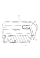
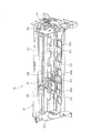
図1は、本発明の実施の形態に係るインクリボンカートリッジを適用したプリンタ10の前方の外観を示す斜視図であり、図2は、プリンタ10を示す側断面図である。図3は、プリンタ10のフレーム構成を示す斜視図である。
プリンタ10は、複数の記録ワイヤを選択的に打ち出す記録ヘッド20と、この記録ヘッド20が搭載されるキャリッジ21とを備え、記録ヘッド20から打ち出された記録ワイヤを記録媒体(以下、シートという。)に打ち付けることによって文字を含む画像を記録するシリアルドットインパクトプリンタである。
Preferred embodiments of the present invention will be described below with reference to the drawings.
FIG. 1 is a perspective view showing the front appearance of a
The
図2に示すように、プリンタ10は、大別すると、記録ユニットを構成するプリンタ本体12と、トラクタユニット13と、シートガイド14とを備え、これらの上方、下方が、図1に示すように、上部ケース15および下部ケース16で覆われる構成となっている。上記シートには、所定長さに裁断されたカットシートと、複数枚が連結された連続シートとがある。カットシートとしては、例えば単票紙、複写紙、通帳またはカットフィルムなどがあり、連続シートとしては連続紙がある。
As shown in FIG. 2, the
プリンタ本体12は、記録ヘッド20と、キャリッジ21と、シート搬送機構を構成するプラテン22及び複数の搬送ローラ23等とを備えている。図3に示すように、プリンタ本体12は、一対のサイドフレーム25、26の間に、背面フレーム27、プラテン22、キャリッジ軸28、複数のローラ軸23a、トラクタユニット13などが架け渡され、キャリッジ軸28にはキャリッジ21が、各ローラ軸23aには搬送ローラ23が設けられている。
キャリッジ21は、キャリッジ軸28に摺動自在に挿通されると共に、記録ヘッド20を搭載し、図示しないステッピングモータにて構成されるキャリッジ駆動モータにより駆動されるタイミングベルト43に結合される。
これらキャリッジ駆動モータ、タイミングベルト43及びキャリッジ軸28はキャリッジ駆動機構として機能し、上記キャリッジ21は、キャリッジ駆動モータの正転又は逆転により、タイミングベルト43を介しキャリッジ軸28に案内されて、上記キャリッジ軸28の軸方向及びプラテン22の長手方向と一致する主走査方向に走行(走査)される。上記記録ヘッド20は、多数の記録ワイヤ(不図示)を備え、これら記録ワイヤをプラテン22に向けて打ち出す。
The printer
The
These carriage drive motor,
搬送ローラ23は、プラテン22に対してプリンタ本体12の前方及び後方に、上下に対に配置されており(一部の搬送ローラ23は不図示)、図示しないシート搬送モータと、このシート搬送モータに連結され、右サイドフレーム26の外側に配列された駆動輪列部41とによって、図2中の時計方向又は反時計方向に回転駆動される。これによって、シートを、プリンタ本体12の前方(シートガイド14側)から後方へ搬送し、また、プリンタ本体12の後方から前方へ搬送することができ、シートは、キャリッジ21の主走査方向と直交する副走査方向に搬送される。
Conveying
トラクタユニット13は、連続シートをシート搬送機構へ供給するものであり、図2に示すように、左右一対のトラクタ30を有する。各トラクタ30は、トラクタ駆動プーリ30aと、トラクタ従動プーリ30bと、これらプーリ30a,30bに巻き掛けられたトラクタベルト31とを備え、図示せぬ駆動機構によってトラクタ駆動プーリ30aを回転駆動し、トラクタベルト31を駆動して連続シートを搬送する。
そして、プリンタ10は、キャリッジ21を主走査方向に走査させ、この移動中に記録ヘッド20によって記録ワイヤの打ち出しを行わせることで一行分の記録を行い、この一行分の記録を完了する度に搬送ローラ23によってシートを所定長搬送させ、1ページの画像を行毎にシートに記録する。
The
Then, the
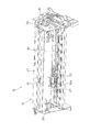
図4は、インクリボンカートリッジ50を装着した状態のプリンタ10のフレーム構成を示す斜視図である。
プリンタ本体12には、ステーショナリー形式のインクリボンカートリッジ50が着脱自在に装着され、インクリボンカートリッジ50に収容されたインクリボン51(図5参照)が記録ヘッド20とプラテン22との間に繰り出される。このため、記録ヘッド20が主走査方向に走行する間に記録ワイヤを突出させると、記録ワイヤはインクリボン51に打ち当てられ、このインクリボン51のインクが、プラテン22と記録ヘッド20との間に搬送されたシートに付着する。これにより、インクリボン51のインクによってシートに文字を含む画像が記録される。
キャリッジ21には、図3にも示すようにリボンマスクホルダ50aが取り付けられ、このリボンマスクホルダ50aによって、インクリボンカートリッジ50から繰り出されたインクリボン51が、記録ヘッド20の記録ワイヤ突出面(図示略)の正面に保持される。また、リボンマスクホルダ50aは、プラテン22の上面に接して搬送されるシート(カットシートまたは連続シート)に不要なインクが付着しないよう、インクリボン51とシートとの接触を防いでいる。
FIG. 4 is a perspective view showing a frame configuration of the
A stationary type
As shown in FIG. 3, a
以下、インクリボンカートリッジ50の構成について詳細に説明する。
図5は、インクリボンカートリッジ50の構成を示す外観斜視図であり、図6は、インクリボンカートリッジ50の平面図であり、図7は、インクリボンカートリッジ50の平断面図である。
図5及び図6に示すように、インクリボンカートリッジ50は平型のカートリッジケース53を有する。このカートリッジケース53は、一面が開口したカートリッジ本体53aに、このカートリッジ本体53aの開口部(不図示)を塞ぐカートリッジカバー(蓋)53bを取り付けた構成となっている。
また、カートリッジケース53の両側端部には、それぞれ腕部52が立設されており、カートリッジケース53から外部に繰り出されたインクリボン51が、2本の腕部52、52の間に架け渡され、上述したように記録ヘッド20の前方に供給される。
Hereinafter, the configuration of the
5 is an external perspective view showing the configuration of the
As shown in FIGS. 5 and 6, the
In addition,
図7に示すように、カートリッジケース53の内部には、インクリボン51を収容するリボン収容部55が形成され、このリボン収容部55には無端形状に形成されたインクリボン51が、折り畳まれて収容される。
リボン収容部55の一方側には、2本の腕部52、52の間に架け渡されたインクリボン51をリボン収容部55内に巻き取る巻取ローラ56及び従動ローラ58が配設されている。巻取ローラ56は、プリンタ本体12に設けられたキャリッジ駆動モータによって駆動され、巻取ローラ56に向けて付勢される従動ローラ58との間にインクリボン51を挟み込んで、リボン収容部55にインクリボン51を送り込む。
また、リボン収容部55の他方側には、インクリボン51がカートリッジケース53の外に排出される出口部55aの手前に、インクリボン51の表裏を反転させるインクリボン反転部55bが設けられている。
As shown in FIG. 7, a
A winding
Further, an ink
インクリボン51は、巻取ローラ56及び従動ローラ58によって、カートリッジケース53の外からリボン収容部55内に巻き取られ、その後、インクリボン反転部55bを通って、カートリッジケース53の外に繰り出され、一方の腕部52から他方の腕部52に向けて移動する。
無端形状のインクリボン51はメビウスの輪状に形成されており、その両面にインクが含浸されている。そして、インクリボン51は、リボン収容部55から繰り出される際にインクリボン反転部55bにおいて表裏が反転されるので、インクリボン51の表裏が交互にシート側に向けられる。これにより、インクリボン51の幅の上下を効率よく利用して、長寿命化を図っている。
また、巻取ローラ56は、図5及び図6に示すようにカートリッジケース53の外に突出する巻取突起54に連結されており、この巻取突起54を手で回して巻取ローラ56を回転させ、インクリボン51を手動で巻き取ることもできる。
The
The
5 and 6, the take-up
そして、出口部55aには、カートリッジケース53の外部に連通する出口通路55cが形成され、この出口通路55cには、インクリボン51に繰り出し抵抗を与えるばね受け部59(受け部)及び板ばね60(押圧部)が配置されている。
ばね受け部59は、出口通路55cを形成するカートリッジケース53の角であるケース隅部を、略円柱状に形成したものである。インクリボン51は、インクリボン反転部55bを出て、ばね受け部59の側面に当接して走行方向を出口通路55c側へ変更し、カートリッジケース53外の腕部52へ向けて走行する。ここで、ばね受け部59は、インクリボン51に接する側面が円柱状の滑らかな曲面となっており、インクリボン51をスムーズに案内して方向変更させる。
板ばね60はばね受け部59に対向して配置され、ばね受け部59との間にインクリボン51を挟む構成となっている。板ばね60は、例えば所定の弾性を有する金属板を打ち抜いて形成されたものであって、その弾性によりばね受け部59に向けてインクリボン51の表面を押圧し、この押圧力によりインクリボン51とばね受け部59との間に摩擦を生じさせ、インクリボン51に繰り出し抵抗を与える。この板ばね60が与える繰り出し抵抗により、インクリボン51は、巻取ローラ56の動作によって必要量だけ繰り出されるので、繰り出し量が巻き取り量を上回ることが無くなり、インクリボン51の弛みが防止される。
An
The
The
カートリッジケース53の内部において、出口通路55cの近傍に、板ばね60の基端部60aが嵌入可能なケース凹部53eが形成され、このケース凹部53eとばね受け部59との間に、ばね受け部59側に突出する突起53fが設けられる。板ばね60の基端部60aがケース凹部53eに嵌め込まれてインクリボン51の走行方向に対して移動しないように支持され、その先端部60bがインクリボン51を挟んでばね受け部59に当接しており、基端部60aと先端部60bとの間で板ばね60が突起53fに接している。このため、板ばね60はケース凹部53e、突起53f、及びばね受け部59により屈曲状態で保持され、その結果としてばね受け部59を押圧する。
Inside the
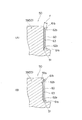
図8(a)は、板ばね60の構成を示す正面図であり、図8(b)は、板ばね60の側面図である。図9は、インクリボンカートリッジ50の要部縦断面図であり、インクリボン51、ばね受け部59、及び板ばね60の接触状態を示している。図9(a)はインクリボンカートリッジ50の使用開始時の状態を示し、図9(b)はインクリボンカートリッジ50の使用開始後の状態を示す。
図8(a)及び図8(b)に示すように、板ばね60は、略矩形状の薄い金属板で形成され、基端部60aには側方に突出する突起60cが一体に形成されている。また、先端部60bにおいては、板ばね60の両側端61a,61bが折り曲げ加工され、折り曲げ部62a,62bが形成されている。符号62a,62bの折り曲げ部は、直線状の折り目を指している。これら折り曲げ部62a,62bは、先端部60bの近傍における側端から、板ばね60の先端に至る斜め方向の直線をなし、板ばね60の先端部60b及びその近傍にのみ形成されており、基端部60aには達していない。
ここで、折り曲げ部62a,62bの折り曲げ角度は任意であるが、その角度が浅くても十分に効果を発揮できる。また、折り曲げ角度が浅い方が、折り曲げ部62a,62bが尖らないため、インクリボン51との接触面積を大きく確保できるという利点がある。このため、折り曲げ部62a,62bの折り曲げ角度は、好ましくは折り曲げ部62a,62b以外の平面部分に対して90度を超えることはなく、より好ましくは、上記平面部分に対して60度以下である。
FIG. 8A is a front view showing the configuration of the
As shown in FIGS. 8A and 8B, the
Here, the bending angle of the
板ばね60において、折り曲げ部62a,62bが形成された部分では、折り曲げ部62a,62bの影響で断面係数が他の部分と異なっており、剛性が高い。しかしながら、板ばね60の基端部60aを含む部分では折り曲げ部62a,62bが形成されていないので、この部分では適度な弾性が保たれている。このため、板ばね60全体としては、インクリボン51を適度な力で押圧するように、適切な弾性を有している。
In the
このように形成された板ばね60は、図9に示すように、折り曲げ部62a,62bがそれぞれインクリボン51の幅より内側に位置しているので、板ばね60のインクリボン51との接触部63の接触幅Wがインクリボン51の幅より狭くなっている。
プリンタ10の動作に伴い、インクリボン51がばね受け部59に接触しながら走行することによって、ばね受け部59は、インクリボン51との摩擦により磨耗する。この場合、ばね受け部59の摩耗によってばね受け部59の表面に凹部が形成され、この凹部にインクリボン51が嵌入して、インクリボン51が板ばね60から逃げるように変位することが想定される。しかしながら、本実施の形態では、板ばね60の先端部60bが、インクリボン51の幅よりも狭い幅でインクリボンに接触しているので、板ばね60はインクリボン51の変位に追従して、インクリボン51とともにばね受け部59の凹部に入り込み、インクリボン51に押圧力を与える。このため、インクリボンカートリッジ50の使用開始から長期間が経過しても、インクリボン51に対しては繰り出し抵抗が途切れることなく与えられる。
As shown in FIG. 9, the
As the
図8(a)中の符号63で示す領域は、板ばね60とインクリボン51(図9参照)とが接触する接触部を示している。また、図8(a)中において、板ばね60の長尺方向における接触部63の接触長さを符号dで示し、板ばね60の短尺方向(幅方向)における接触部63の最大幅を符号Wで示す。
接触部63は、折り曲げ部62a,62bの間の領域であり、折り曲げ部62a,62bが形成されていない部分と同様の平面となっている。接触部63は、板ばね60自身の弾性によってインクリボン51に対して押圧され、インクリボン51の面に対して幅方向に沿って接触する。
図9(a)に示すように、板ばね60の接触部63は、ばね受け部59の面に対してほぼ平行であり、ばね受け部59との間にインクリボン51を挟んだ状態では接触部63、インクリボン51及びばね受け部59が、インクリボン51の幅方向に沿って、接触している。ここで、インクリボン51の長手方向における接触状態は、板ばね60の屈曲の度合いによって変化する。しかしながら、板ばね60の接触部63がばね受け部59の面に略平行なため、接触部63がインクリボン51の幅方向に一様に接触することは変わりない。このため、板ばね60からインクリボン51に加わる押圧力はインクリボン51の幅方向に分散されるので、インクリボン51の狭い範囲に押圧力が集中することがなく、インクリボン51が損傷することはない。
A region indicated by
The
As shown in FIG. 9A, the
また、プリンタ10の使用に伴ってインクリボン51が走行することにより、ばね受け部59は、インクリボン51に接触する面が摩耗して凹部となる。この摩耗した状態を、図9(b)に示す。
図9(b)に示す状態では、ばね受け部59の摩耗によって凹部59aが形成されている。インクリボン51とばね受け部59との接触面において、板ばね60により押圧された部分では特に摩擦力が高いので、凹部59aは接触部63に重なる位置を中心として、インクリボン51がばね受け部59に接触する範囲に形成される。このため、凹部59aの幅は、接触部63の幅より広い。
凹部59aには、図9(b)に示すように、接触部63により押圧されたインクリボン51が入り込む。接触部63の幅は凹部59aの幅より小さいので、プリンタ10の継続使用に伴って凹部59aが深くなり、インクリボン51が深く沈み込んでも、接触部63が凹部59aに入り込んでインクリボン51を押圧する。
従って、板ばね60は、インクリボン51との摩擦によりばね受け部59が摩耗して、凹部59aが形成されても、この摩耗に追従して凹部59aに入り込み、インクリボン51を押圧するので、インクリボン51に対して安定して繰り出し抵抗を与え続けることができる。
Further, when the
In the state shown in FIG. 9B, the
As shown in FIG. 9B, the
Accordingly, even if the
さらに、板ばね60とインクリボン51との接触部63の両端は折り曲げ部62a,62bであり、板ばね60の側端61a,61bがインクリボン51に接触することがない。このため、板ばね60の側端61a,61bが鋭利であったとしても、インクリボン51の損傷を抑制することができる。
Furthermore, both ends of the
上述したように、カートリッジケース53は、カートリッジカバー53bを取り外して開くことができ、このカートリッジカバー53bを外した状態で、リボン収容部55内のインクリボン51を取り出して、新しいインクリボン51に交換することができる。
このインクリボン51の交換作業は、大別して、以下の工程で行われる。
工程1.カートリッジカバー53bを外す。
工程2.インクリボン51を、巻取ローラ56と従動ローラ58との間、及び、板ばね60とばね受け部59との間から外し、カートリッジケース53から取り出す。
工程3.新しいインクリボン51を、巻取ローラ56と従動ローラ58との間、及び、板ばね60とばね受け部59との間に差し入れ、残りの部分をリボン収容部55に収める。
工程4.新しいインクリボン51を、2本の腕部52の間に架け渡す。
工程5.カートリッジカバー53bを取り付けて、巻取突起54を巻いてインクリボン51の弛みを取る。
As described above, the
The replacement operation of the
Step 1. Remove the
Step 2. The
Step 3. A
Step 4. A
Step 5. The
このうち工程3においては、板ばね60とばね受け部59との間にインクリボン51を差し入れる必要がある。本実施の形態では、上述したように、カートリッジカバー53b側において、板ばね60の側端61bが折り曲げられ、折り曲げ部62bが形成されている。このため、図9に符号δで示すように、ばね受け部59と板ばね60との間に隙間が形成される。従って、上記の工程3では、隙間δにインクリボン51を入り込ませることで、ばね受け部59と板ばね60との間に、インクリボン51を容易に挿入することができ、インクリボン51の交換作業を容易に行うことができる。ここで、隙間δにインクリボン51を入り込ませる作業がしやすくなるよう、折り曲げ部62a,62bの折り曲げ角度が所定角度以上であることが好ましい。例えば、折り曲げ部62a,62bの幅が3ミリメートルである場合に、1ミリメートルの隙間δを確保するには、折り曲げ角は18度以上となる。このように、一般的なサイズのインクリボンカートリッジ50において十分な隙間δを確保するため、折り曲げ部62a,62bの折り曲げ角は、折り曲げ部62a,62b以外の平面部分に対して15度以上であれば好ましく、より好ましくは、20度以上である。
なお、本実施の形態では、板ばね60の短尺方向の折り曲げ量Lは、折り曲げ部62a,62bで同一に設定されている。
Of these, in step 3, it is necessary to insert the
In the present embodiment, the bending amount L in the short direction of the
以上説明したように、本実施の形態によれば、板ばね60とインクリボン51とが接触する幅がインクリボン51の幅より狭くなるので、インクリボン51との摩擦によりばね受け部59が磨耗し、この摩耗部分にインクリボン51が沈み込んでも、板ばね60がインクリボン51に追従する。言い換えれば、板ばね60の接触部63が、インクリボン51の幅内でインクリボン51に接触するので、インクリボン51との摩擦により受け部が磨耗し、この摩耗部分にインクリボン51が沈み込んでも、板ばね60がインクリボン51に追従するので、板ばね60とインクリボン51とが接触する状態を保つことができる。これにより、長期間にわたって、インクリボン51に安定した繰り出し抵抗を与えることができる。
そして、板ばね60の側端に折り曲げ部62a,62bを形成することによって板ばね60とインクリボン51とが接触する幅を狭くするので、板ばね60の側端61a,61bがインクリボン51に接触せず、インクリボン51が損傷するおそれがない。
さらに、インクリボン51の幅方向における端部が折り曲げ部62a,62bに接触可能なため、板ばね60のエッジがインクリボン51の端部に接触せず、インクリボン51の端部の損傷を防止できる。
As described above, according to the present embodiment, the width of contact between the
Since the
Further, since the end portion in the width direction of the
また、板ばね60の両側端に折り曲げ部62a,62bを形成し、この折り曲げ部62a,62bの間でインクリボン51に接するので、板ばね60の切端がインクリボン51に接することがなく、インクリボン51の損傷を防止できる。また、板ばね60が平面状の接触部63でインクリボン51と接するので、板ばね60とインクリボン51との接触面積を広く確保できる。さらに、折り曲げ部62a,62bの間では板ばね60がばね受け部59に対して平行に接するので、板ばね60とインクリボン51とばね受け部59とが相互に広い面積で接触し、インクリボン51に対して安定した繰り出し抵抗を与えることができる。
Further, the
また、板ばね60がカートリッジケース53に支持される基端部60aには、折り曲げ部62a,62bが形成されていないので、板ばね60の適度な弾性が保たれ、インクリボン51に適度な繰り出し抵抗を与えることができる。カートリッジケース53の蓋であるカートリッジカバー53bを開放することで、インクリボン51を容易に交換できる。
さらにまた、ばね受け部59がカートリッジケース53と一体に構成されたことにより、部品点数を削減し、製造工程の簡略化を図ることが可能になる。さらに、ばね受け部59の強度を容易に確保することができ、板ばね60とインクリボン51とを確実に保持して、長期にわたって安定した繰り出し抵抗を与えることができる。さらに、ばね受け部59を独立した部品とした場合に比べ、部品を紛失するおそれがなく、管理上の手間を省くことができる。
Further, since the
Furthermore, since the
なお、上記実施の形態では、板ばね60の両側端61a,61bに折り曲げ部62a,62bを形成した例について説明したが、本発明はこれに限定されるものではなく、板ばね60において、カートリッジカバー53b側の側端61bにのみ、折り曲げ部62bを設けた構成としてもよい。この場合も、ばね受け部59と板ばね60との間に隙間δが形成されることで、インクリボン51の交換時に、板ばね60とばね受け部59との間にインクリボン51を容易に挿入することができる。
In the above-described embodiment, the example in which the
さらに、上記実施の形態では、板ばね60の短尺方向の折り曲げ量Lは、折り曲げ部62a,62bで同一であるものとして説明したが、この折り曲げ量Lを不均等にしてもよい。
すなわち、図10に示すように、板ばね60において、カートリッジカバー53b側の側端61bに形成された折り曲げ部162bの折り曲げ量を、他方の側端61aに形成された折り曲げ部62aより大きくしてもよい。
この図10に示す構成では、カートリッジカバー53b側に、上述した隙間δ(図9)より大きな隙間δ´が形成されるので、板ばね60とばね受け部59との間にインクリボン51を差し入れる作業が容易である。このため、インクリボン51の交換時に、ばね受け部59と板ばね60との間にインクリボン51を挿入する作業を、より容易に行うことができる。
Furthermore, in the above-described embodiment, the bending amount L in the short direction of the
That is, as shown in FIG. 10, in the
In the configuration shown in FIG. 10, a gap δ ′ larger than the gap δ (FIG. 9) is formed on the
さらに、上記実施の形態では、折り曲げ部62a,62bが直線的な折り曲げ加工により形成された場合を例に挙げて説明したが、例えば、板ばね60の側端61a,61bを丸める加工によって、折り曲げ部62a,62bを形成してもよい。
また、上記実施の形態では、本発明をステーショナリー形式のインクリボンカートリッジ50に適用した場合について説明したが、本発明はこれに限定されるものではなく、オンキャリッジ形式のインクリボンカートリッジにも適用可能である。
また、上記実施の形態では、板ばね60を折り曲げて接触部63を設けた例について説明したが、板ばね60のインクリボン51との接触部63を成形やプレス鍛造で独立部品とし、圧縮ばねによりインクリボン51の表面を押圧する構成とすることも可能である。ただし、上記実施の形態で説明したように、板ばね60を用いた構成のほうが、押圧部分とばね部分を1部品で構成することができるので、部品の管理上の手間を省くことができ、構造の簡略性やコストの面においても有利である。さらに、インクリボン51の繰り出し抵抗を与える板ばね60(押圧部)及びばね受け部59(受け部)の位置は、出口部55aに限定されず、インクリボン51の走行方向において上流側に位置する腕部52の先端に配置する構成としても良い。ただし、腕部52間のインクリボン51にテンションを与えてインクリボン51を安定して走行させる点で、インクリボン51の出口側に板ばね60及びばね受け部59を設けると、上流側の腕部52部分を走行するインクリボン51にもテンションを与えることができ、インクリボン51を安定供給できるので、有利である。
Furthermore, in the above-described embodiment, the case where the
In the above-described embodiment, the case where the present invention is applied to the stationery type
Moreover, although the said embodiment demonstrated the example which bent the leaf |
10…プリンタ、12…プリンタ本体、20…記録ヘッド、21…キャリッジ、50…インクリボンカートリッジ、51…インクリボン、53…カートリッジケース、53a…カートリッジ本体、53b…カートリッジカバー(蓋)、54…ばね受け部、55b…出口部、59…ばね受け部(受け部)、60…板ばね(押圧部)、60a…基端部、60b…先端部、61a,61b…側端、62a,62b…折り曲げ部(第2接触部分、第3接触部分)、63…接触部(第1接触部分)、L…折り曲げ量、δ、δ´…隙間。
DESCRIPTION OF
Claims (6)
前記カートリッジケースから前記インクリボンが繰り出される出口部に先端部を向けて配置され、この出口部から繰り出される前記インクリボンを挟んで繰り出し抵抗を与える板ばね及びばね受け部と、を備え、
前記板ばねの両側端には、前記板ばねの先端部の近傍における側端から、前記板ばねの先端に至る斜め方向の直線をなす、前記板ばねの先端を前記インクリボンの幅より狭くする折り曲げ部が形成され、これら折り曲げ部の間の領域を、前記板ばねと前記インクリボンとが接触する接触部として形成したこと、
を特徴とするインクリボンカートリッジ。 A cartridge case for containing the ink ribbon;
A leaf spring and a spring receiving portion which are arranged with an end portion directed toward an outlet portion from which the ink ribbon is drawn out from the cartridge case, and which gives out feeding resistance across the ink ribbon fed out from the outlet portion,
Both side ends of the plate spring from the side end in the vicinity of the tip portion of the plate spring, forming the oblique direction of a straight line extending to the tip of the leaf spring, the tip of the plate spring narrower than the width of the ink ribbon A bent portion is formed, and an area between the bent portions is formed as a contact portion where the leaf spring and the ink ribbon contact each other,
An ink ribbon cartridge.
を特徴とする請求項1記載のインクリボンカートリッジ。 The contact portion is a plane ;
The ink ribbon cartridge according to claim 1.
前記板ばねの基端部に達しないように前記折り曲げ部が形成されたこと、
を特徴とする請求項1または2記載のインクリボンカートリッジ。 The leaf spring is arranged such that its base end is supported by the cartridge case and its tip is in contact with the ink ribbon,
The bent portion is formed so as not to reach the base end of the leaf spring;
The ink ribbon cartridge according to claim 1 or 2 .
を特徴とする請求項1から3のいずれかに記載のインクリボンカートリッジ。 On one side of the cartridge case, said plate opening for exposing the interior, including a spring and the receiving portion is formed, the lid for closing the opening is disposed,
The ink ribbon cartridge according to any one of claims 1 to 3 .
を特徴とする請求項4記載のインクリボンカートリッジ。 The amount of bending of the bent portion formed at the side end of the lid side is larger than the amount of bending of the bent portion formed at the other side end;
The ink ribbon cartridge according to claim 4 .
を特徴とする請求項1から5のいずれかに記載のインクリボンカートリッジ。 The spring receiver is configured integrally with the cartridge case;
The ink ribbon cartridge according to any one of claims 1 to 5 , wherein:
Priority Applications (2)
| Application Number | Priority Date | Filing Date | Title |
|---|---|---|---|
| JP2008283324A JP5228809B2 (en) | 2008-11-04 | 2008-11-04 | Ink ribbon cartridge |
| CN2009102092204A CN101734026B (en) | 2008-11-04 | 2009-11-02 | Ink band box and recording apparatus |
Applications Claiming Priority (1)
| Application Number | Priority Date | Filing Date | Title |
|---|---|---|---|
| JP2008283324A JP5228809B2 (en) | 2008-11-04 | 2008-11-04 | Ink ribbon cartridge |
Publications (2)
| Publication Number | Publication Date |
|---|---|
| JP2010110919A JP2010110919A (en) | 2010-05-20 |
| JP5228809B2 true JP5228809B2 (en) | 2013-07-03 |
Family
ID=42299892
Family Applications (1)
| Application Number | Title | Priority Date | Filing Date |
|---|---|---|---|
| JP2008283324A Active JP5228809B2 (en) | 2008-11-04 | 2008-11-04 | Ink ribbon cartridge |
Country Status (2)
| Country | Link |
|---|---|
| JP (1) | JP5228809B2 (en) |
| CN (1) | CN101734026B (en) |
Families Citing this family (5)
| Publication number | Priority date | Publication date | Assignee | Title |
|---|---|---|---|---|
| JP2012200991A (en) * | 2011-03-25 | 2012-10-22 | Seiko Epson Corp | Ink ribbon cartridge and printer |
| CN102825915A (en) * | 2011-06-17 | 2012-12-19 | 致伸科技股份有限公司 | Printing device |
| CN103009833B (en) * | 2012-12-10 | 2015-09-09 | 佛山市顺德区高宝实业发展有限公司 | Platform machine enters band model and produces color ribbon rack technique |
| CN103332027B (en) * | 2013-06-28 | 2015-05-06 | 上海宜达胜电脑用品有限公司 | Printer ribbon cartridge with detachable ribbon cartridge inner box |
| JP6880643B2 (en) * | 2016-10-19 | 2021-06-02 | カシオ計算機株式会社 | Printing equipment |
Family Cites Families (5)
| Publication number | Priority date | Publication date | Assignee | Title |
|---|---|---|---|---|
| JPS6014599Y2 (en) * | 1979-12-26 | 1985-05-09 | 沖電気工業株式会社 | Endless ink ribbon cartridge |
| JPS6211668A (en) * | 1985-07-09 | 1987-01-20 | Fuji Xerox Co Ltd | Thermal transfer recording apparatus |
| JP2522077Y2 (en) * | 1990-06-25 | 1997-01-08 | 株式会社リコー | Ink sheet cartridge |
| JP4654146B2 (en) * | 2006-03-22 | 2011-03-16 | アルプス電気株式会社 | Ink sheet cartridge |
| CN2925890Y (en) * | 2006-07-01 | 2007-07-25 | 珠海天威技术开发有限公司 | Color-band box of miniature printer |
-
2008
- 2008-11-04 JP JP2008283324A patent/JP5228809B2/en active Active
-
2009
- 2009-11-02 CN CN2009102092204A patent/CN101734026B/en active Active
Also Published As
| Publication number | Publication date |
|---|---|
| CN101734026A (en) | 2010-06-16 |
| JP2010110919A (en) | 2010-05-20 |
| CN101734026B (en) | 2012-07-18 |
Similar Documents
| Publication | Publication Date | Title |
|---|---|---|
| JP4561830B2 (en) | Ribbon cartridge and recording apparatus | |
| JP5228809B2 (en) | Ink ribbon cartridge | |
| JP4984088B2 (en) | Sheet conveying device, driven roller mold and image recording device | |
| JP2014156079A (en) | Inkjet recording apparatus | |
| JP2003251904A (en) | Ribbon cartridge of recorder, and recorder | |
| US7165741B2 (en) | Cassette for rolled recording medium and image forming apparatus | |
| JP4992559B2 (en) | Serial impact printer | |
| CN106004119A (en) | Printer | |
| CN101269583B (en) | Recording device and ink belt case | |
| JPH10250184A (en) | Recorder | |
| CN112140752A (en) | Box | |
| KR100896022B1 (en) | Printer | |
| JP4141893B2 (en) | Sheet supply guide and recording apparatus | |
| JP3654344B2 (en) | Cutter holder and ink jet recording apparatus provided with the same | |
| US11924388B2 (en) | Image recording apparatus and feed tray that includes a side guide inside a pair of sidewalls for roll paper | |
| JP5959408B2 (en) | Printer | |
| JP3804435B2 (en) | Recording device | |
| JP2005219269A (en) | Ink ribbon winding device, ribbon cartridge, and recording device | |
| JP3979154B2 (en) | Paper discharge unit and recording apparatus | |
| JP2005199583A (en) | Carriage and recording apparatus | |
| JP5353452B2 (en) | Conveying apparatus and image recording apparatus | |
| JP5533434B2 (en) | printer | |
| JP3686431B2 (en) | Printer | |
| JP6186740B2 (en) | Image recording device | |
| CN112140751A (en) | Box |
Legal Events
| Date | Code | Title | Description |
|---|---|---|---|
| A621 | Written request for application examination |
Free format text: JAPANESE INTERMEDIATE CODE: A621 Effective date: 20110803 |
|
| RD02 | Notification of acceptance of power of attorney |
Free format text: JAPANESE INTERMEDIATE CODE: A7422 Effective date: 20110803 |
|
| A977 | Report on retrieval |
Free format text: JAPANESE INTERMEDIATE CODE: A971007 Effective date: 20121128 |
|
| A131 | Notification of reasons for refusal |
Free format text: JAPANESE INTERMEDIATE CODE: A131 Effective date: 20121204 |
|
| A521 | Written amendment |
Free format text: JAPANESE INTERMEDIATE CODE: A523 Effective date: 20130128 |
|
| TRDD | Decision of grant or rejection written | ||
| A01 | Written decision to grant a patent or to grant a registration (utility model) |
Free format text: JAPANESE INTERMEDIATE CODE: A01 Effective date: 20130219 |
|
| A61 | First payment of annual fees (during grant procedure) |
Free format text: JAPANESE INTERMEDIATE CODE: A61 Effective date: 20130304 |
|
| FPAY | Renewal fee payment (event date is renewal date of database) |
Free format text: PAYMENT UNTIL: 20160329 Year of fee payment: 3 |
|
| R150 | Certificate of patent or registration of utility model |
Ref document number: 5228809 Country of ref document: JP Free format text: JAPANESE INTERMEDIATE CODE: R150 Free format text: JAPANESE INTERMEDIATE CODE: R150 |
|
| S531 | Written request for registration of change of domicile |
Free format text: JAPANESE INTERMEDIATE CODE: R313531 |
|
| R350 | Written notification of registration of transfer |
Free format text: JAPANESE INTERMEDIATE CODE: R350 |