JP5223003B2 - 物理量センサ - Google Patents
物理量センサ Download PDFInfo
- Publication number
- JP5223003B2 JP5223003B2 JP2011518374A JP2011518374A JP5223003B2 JP 5223003 B2 JP5223003 B2 JP 5223003B2 JP 2011518374 A JP2011518374 A JP 2011518374A JP 2011518374 A JP2011518374 A JP 2011518374A JP 5223003 B2 JP5223003 B2 JP 5223003B2
- Authority
- JP
- Japan
- Prior art keywords
- leg
- movable
- anchor
- physical quantity
- support
- Prior art date
- Legal status (The legal status is an assumption and is not a legal conclusion. Google has not performed a legal analysis and makes no representation as to the accuracy of the status listed.)
- Expired - Fee Related
Links
- 238000006073 displacement reaction Methods 0.000 claims description 38
- 238000013459 approach Methods 0.000 claims description 11
- 238000001514 detection method Methods 0.000 claims description 8
- 230000005484 gravity Effects 0.000 claims description 8
- XUIMIQQOPSSXEZ-UHFFFAOYSA-N Silicon Chemical compound [Si] XUIMIQQOPSSXEZ-UHFFFAOYSA-N 0.000 description 22
- 229910052710 silicon Inorganic materials 0.000 description 22
- 239000010703 silicon Substances 0.000 description 22
- 239000000758 substrate Substances 0.000 description 22
- 239000002184 metal Substances 0.000 description 14
- 230000035945 sensitivity Effects 0.000 description 13
- 230000001133 acceleration Effects 0.000 description 11
- 230000007246 mechanism Effects 0.000 description 11
- 230000000052 comparative effect Effects 0.000 description 9
- 238000005530 etching Methods 0.000 description 7
- 238000006243 chemical reaction Methods 0.000 description 6
- 230000008878 coupling Effects 0.000 description 4
- 238000010168 coupling process Methods 0.000 description 4
- 238000005859 coupling reaction Methods 0.000 description 4
- 230000009471 action Effects 0.000 description 3
- 230000007935 neutral effect Effects 0.000 description 3
- 230000015572 biosynthetic process Effects 0.000 description 2
- 238000000708 deep reactive-ion etching Methods 0.000 description 2
- 238000005516 engineering process Methods 0.000 description 2
- 230000005496 eutectics Effects 0.000 description 2
- 238000002474 experimental method Methods 0.000 description 2
- 238000004519 manufacturing process Methods 0.000 description 2
- 238000000034 method Methods 0.000 description 2
- 238000007747 plating Methods 0.000 description 2
- 238000004544 sputter deposition Methods 0.000 description 2
- 229910004298 SiO 2 Inorganic materials 0.000 description 1
- 230000008859 change Effects 0.000 description 1
- 239000004020 conductor Substances 0.000 description 1
- 238000010586 diagram Methods 0.000 description 1
- 238000009792 diffusion process Methods 0.000 description 1
- 239000013013 elastic material Substances 0.000 description 1
- 230000007257 malfunction Effects 0.000 description 1
- 238000005259 measurement Methods 0.000 description 1
- 239000007769 metal material Substances 0.000 description 1
- 230000004048 modification Effects 0.000 description 1
- 238000012986 modification Methods 0.000 description 1
- 238000000206 photolithography Methods 0.000 description 1
- 230000002265 prevention Effects 0.000 description 1
- 230000008569 process Effects 0.000 description 1
- 238000012545 processing Methods 0.000 description 1
- 238000001179 sorption measurement Methods 0.000 description 1
Images


Classifications
-
- G—PHYSICS
- G01—MEASURING; TESTING
- G01P—MEASURING LINEAR OR ANGULAR SPEED, ACCELERATION, DECELERATION, OR SHOCK; INDICATING PRESENCE, ABSENCE, OR DIRECTION, OF MOVEMENT
- G01P15/00—Measuring acceleration; Measuring deceleration; Measuring shock, i.e. sudden change of acceleration
- G01P15/02—Measuring acceleration; Measuring deceleration; Measuring shock, i.e. sudden change of acceleration by making use of inertia forces using solid seismic masses
- G01P15/08—Measuring acceleration; Measuring deceleration; Measuring shock, i.e. sudden change of acceleration by making use of inertia forces using solid seismic masses with conversion into electric or magnetic values
-
- B—PERFORMING OPERATIONS; TRANSPORTING
- B81—MICROSTRUCTURAL TECHNOLOGY
- B81B—MICROSTRUCTURAL DEVICES OR SYSTEMS, e.g. MICROMECHANICAL DEVICES
- B81B3/00—Devices comprising flexible or deformable elements, e.g. comprising elastic tongues or membranes
- B81B3/0002—Arrangements for avoiding sticking of the flexible or moving parts
- B81B3/001—Structures having a reduced contact area, e.g. with bumps or with a textured surface
-
- B—PERFORMING OPERATIONS; TRANSPORTING
- B81—MICROSTRUCTURAL TECHNOLOGY
- B81B—MICROSTRUCTURAL DEVICES OR SYSTEMS, e.g. MICROMECHANICAL DEVICES
- B81B3/00—Devices comprising flexible or deformable elements, e.g. comprising elastic tongues or membranes
- B81B3/0018—Structures acting upon the moving or flexible element for transforming energy into mechanical movement or vice versa, i.e. actuators, sensors, generators
- B81B3/0021—Transducers for transforming electrical into mechanical energy or vice versa
-
- G—PHYSICS
- G01—MEASURING; TESTING
- G01P—MEASURING LINEAR OR ANGULAR SPEED, ACCELERATION, DECELERATION, OR SHOCK; INDICATING PRESENCE, ABSENCE, OR DIRECTION, OF MOVEMENT
- G01P15/00—Measuring acceleration; Measuring deceleration; Measuring shock, i.e. sudden change of acceleration
- G01P15/02—Measuring acceleration; Measuring deceleration; Measuring shock, i.e. sudden change of acceleration by making use of inertia forces using solid seismic masses
- G01P15/08—Measuring acceleration; Measuring deceleration; Measuring shock, i.e. sudden change of acceleration by making use of inertia forces using solid seismic masses with conversion into electric or magnetic values
- G01P15/0802—Details
-
- G—PHYSICS
- G01—MEASURING; TESTING
- G01P—MEASURING LINEAR OR ANGULAR SPEED, ACCELERATION, DECELERATION, OR SHOCK; INDICATING PRESENCE, ABSENCE, OR DIRECTION, OF MOVEMENT
- G01P15/00—Measuring acceleration; Measuring deceleration; Measuring shock, i.e. sudden change of acceleration
- G01P15/02—Measuring acceleration; Measuring deceleration; Measuring shock, i.e. sudden change of acceleration by making use of inertia forces using solid seismic masses
- G01P15/08—Measuring acceleration; Measuring deceleration; Measuring shock, i.e. sudden change of acceleration by making use of inertia forces using solid seismic masses with conversion into electric or magnetic values
- G01P15/125—Measuring acceleration; Measuring deceleration; Measuring shock, i.e. sudden change of acceleration by making use of inertia forces using solid seismic masses with conversion into electric or magnetic values by capacitive pick-up
-
- G—PHYSICS
- G01—MEASURING; TESTING
- G01P—MEASURING LINEAR OR ANGULAR SPEED, ACCELERATION, DECELERATION, OR SHOCK; INDICATING PRESENCE, ABSENCE, OR DIRECTION, OF MOVEMENT
- G01P15/00—Measuring acceleration; Measuring deceleration; Measuring shock, i.e. sudden change of acceleration
- G01P15/02—Measuring acceleration; Measuring deceleration; Measuring shock, i.e. sudden change of acceleration by making use of inertia forces using solid seismic masses
- G01P15/08—Measuring acceleration; Measuring deceleration; Measuring shock, i.e. sudden change of acceleration by making use of inertia forces using solid seismic masses with conversion into electric or magnetic values
- G01P2015/0805—Measuring acceleration; Measuring deceleration; Measuring shock, i.e. sudden change of acceleration by making use of inertia forces using solid seismic masses with conversion into electric or magnetic values being provided with a particular type of spring-mass-system for defining the displacement of a seismic mass due to an external acceleration
- G01P2015/0822—Measuring acceleration; Measuring deceleration; Measuring shock, i.e. sudden change of acceleration by making use of inertia forces using solid seismic masses with conversion into electric or magnetic values being provided with a particular type of spring-mass-system for defining the displacement of a seismic mass due to an external acceleration for defining out-of-plane movement of the mass
- G01P2015/0825—Measuring acceleration; Measuring deceleration; Measuring shock, i.e. sudden change of acceleration by making use of inertia forces using solid seismic masses with conversion into electric or magnetic values being provided with a particular type of spring-mass-system for defining the displacement of a seismic mass due to an external acceleration for defining out-of-plane movement of the mass for one single degree of freedom of movement of the mass
- G01P2015/0837—Measuring acceleration; Measuring deceleration; Measuring shock, i.e. sudden change of acceleration by making use of inertia forces using solid seismic masses with conversion into electric or magnetic values being provided with a particular type of spring-mass-system for defining the displacement of a seismic mass due to an external acceleration for defining out-of-plane movement of the mass for one single degree of freedom of movement of the mass the mass being suspended so as to only allow movement perpendicular to the plane of the substrate, i.e. z-axis sensor
-
- G—PHYSICS
- G01—MEASURING; TESTING
- G01P—MEASURING LINEAR OR ANGULAR SPEED, ACCELERATION, DECELERATION, OR SHOCK; INDICATING PRESENCE, ABSENCE, OR DIRECTION, OF MOVEMENT
- G01P15/00—Measuring acceleration; Measuring deceleration; Measuring shock, i.e. sudden change of acceleration
- G01P15/02—Measuring acceleration; Measuring deceleration; Measuring shock, i.e. sudden change of acceleration by making use of inertia forces using solid seismic masses
- G01P15/08—Measuring acceleration; Measuring deceleration; Measuring shock, i.e. sudden change of acceleration by making use of inertia forces using solid seismic masses with conversion into electric or magnetic values
- G01P2015/0862—Measuring acceleration; Measuring deceleration; Measuring shock, i.e. sudden change of acceleration by making use of inertia forces using solid seismic masses with conversion into electric or magnetic values being provided with particular means being integrated into a MEMS accelerometer structure for providing particular additional functionalities to those of a spring mass system
- G01P2015/0871—Measuring acceleration; Measuring deceleration; Measuring shock, i.e. sudden change of acceleration by making use of inertia forces using solid seismic masses with conversion into electric or magnetic values being provided with particular means being integrated into a MEMS accelerometer structure for providing particular additional functionalities to those of a spring mass system using stopper structures for limiting the travel of the seismic mass
Landscapes
- Physics & Mathematics (AREA)
- General Physics & Mathematics (AREA)
- Engineering & Computer Science (AREA)
- Computer Hardware Design (AREA)
- Microelectronics & Electronic Packaging (AREA)
- Chemical & Material Sciences (AREA)
- Analytical Chemistry (AREA)
- Pressure Sensors (AREA)
Description
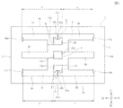
前記支持部には、前記支持部が回動して前記可動部が高さ方向に変位したときに前記可動部の変位方向に対し逆方向に変位して前記可動部の変位を抑制するための脚部が設けられていることを特徴とするものである。
前記支持部は、前記アンカ部と前記可動部間を連結する第1連結腕と、前記アンカ部から前記第1連結腕とは逆方向に延び、前記支持部が回動して前記可動部が高さ方向に変位したときに前記可動部の変位方向に対し逆方向に変位する脚部とを有して構成されており、
前記脚部が前記可動部の変位方向に対し逆方向に変位したときに、前記脚部が接近する対向部には、前記脚部と対向する位置にストッパ面が設けられていることを特徴とするものである。
前記アンカ部は、左右方向(Y)に間隔を空けて配置された左側アンカ部と、右側アンカ部とを有して構成され、
前記支持部は、前記左側アンカ部に連結され、前記左側アンカ部よりも前方(X1)に前記第1連結腕が延び後方(X2)に前記脚部が延びる第1支持部と、前記右側アンカ部に連結され、前記右側アンカ部よりも後方(X2)に前記第1連結腕が延び前方(X1)に前記脚部が延びる第2支持部とを有して構成され、
前記第2連結腕は、前記左側アンカ部と前記可動部の間に位置し、前記第1支持部の前記第1連結腕とは逆方向に延びる左側第2連結腕と、前記前記右側アンカ部と前記可動部の間に位置し、前記第2支持部の前記第1連結腕とは逆方向に延びる右側第2連結腕とを有して構成されることが好ましい。
前記ストッパ面は、前記脚部の幅寸法よりも小さい第1突起部の表面であり、前記ストッパ面は、前記脚部に対し前記脚部の先端面の角部よりも内側で対向していることが好ましい。
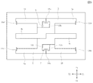
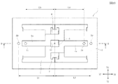
図6に示すように、連結部16aでは、可動部2に溝19が形成されており、この溝19の内部において、右側第2連結腕15と、可動部2とを繋ぐトーションバー(ばね部)20aが設けられている。このトーションバー20aは、可動部2および右側第2連結腕15と同様にシリコンで形成されている。すなわち、長方形のシリコン基板をエッチングして、可動部2や右側第2連結腕15を分離する際に、可動部2と右側第2連結腕15とを連結するようにシリコン基板の一部を残しシリコンを円柱状や角柱状に加工して、トーションバー20aが形成されている。図6では、トーションバー20aの厚さは、可動部2の厚さに比べて薄くなっているが、同じ厚さであってもよい。すなわちトーションバー20aとなる部分のシリコン基板をエッチングにて幅細に切り出すことで、ばね性を持たせることが出来る。

F=Fr1+Fr2
Fr1・L1=Fr2・L2である。ここで、Fr1、Fr2は反力である。
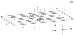
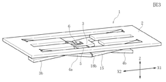
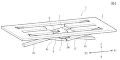
2 可動部
3,4 支持部
3a,4a 第1連結腕
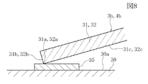
3b,4b 脚部
5 中央アンカ部
6 左側アンカ部
7 右側アンカ部
10 固定部
11a,11b,16a,16b,18a,18b,18c 連結部
12a,12b,13a,13b,17a,17b 支点連結部
14、15 第2連結腕
20a〜20e トーションバー(ばね部)
22 ばね部
30 対向部
30a 対向部の表面(ストッパ面)
31,32 脚部の先端部
35 基台
50、51 突起部
F 慣性力
Fr1、Fr2 反力
Claims (21)
- 固定支持されるアンカ部と、高さ方向に変位する可動部と、前記アンカ部と前記可動部とに回動自在に連結された支持部と、前記可動部の変位を検知するための検知部とを有しており、
前記支持部には、前記支持部が回動して前記可動部が高さ方向に変位したときに前記可動部の変位方向に対し逆方向に変位して前記可動部の変位を抑制するための脚部が設けられ、
前記支持部には、前記アンカ部と前記可動部間を連結する第1連結腕と、前記アンカ部から前記第1連結腕とは逆方向に延びる前記脚部とが形成されており、前記支持部が回動したときに前記アンカ部と前記第1連結腕間の支点連結部を中心として前記第1連結腕と前記脚部とが逆方向に変位し、
前記脚部を備える前記支持部は複数設けられ、一方の前記支持部に設けられた前記第1連結腕と、他方の前記支持部に設けられた前記第1連結腕とは、前記アンカ部を介して逆方向に延びており、一方の前記第1支持部に設けられた前記脚部と他方の前記第1支持部に設けられた前記脚部とは前記アンカ部を介して逆方向に延びていることを特徴とする物理量センサ。 - 前記脚部が前記可動部の変位方向に対し逆方向に変位したときに前記脚部が接近する対向部には、前記脚部と対向する位置にストッパ面が設けられている請求項1記載の物理量センサ。
- 固定支持されるアンカ部と、高さ方向に変位する可動部と、前記アンカ部と前記可動部とに回動自在に連結された支持部と、前記可動部の変位を検知するための検知部とを有しており、
前記支持部は、前記アンカ部と前記可動部間を連結する第1連結腕と、前記アンカ部から前記第1連結腕とは逆方向に延び、前記支持部が回動して前記可動部が高さ方向に変位したときに前記可動部の変位方向に対し逆方向に変位する脚部とを有して構成されており、
前記脚部が前記可動部の変位方向に対し逆方向に変位したときに、前記脚部が接近する対向部には、前記脚部と対向する位置にストッパ面が設けられており、
前記脚部を備える前記支持部は複数設けられ、一方の前記支持部に設けられた前記第1連結腕と、他方の前記支持部に設けられた前記第1連結腕とは、前記アンカ部を介して逆方向に延びており、一方の前記第1支持部に設けられた前記脚部と他方の前記第1支持部に設けられた前記脚部とは前記アンカ部を介して逆方向に延びていることを特徴とする物理量センサ。 - 同軸上で測定された前記支点連結部と前記第1連結腕間の長さ寸法a、及び前記支点連結部と前記脚部間の長さ寸法bとが長さ寸法a<長さ寸法bの関係を満たす請求項1又は2に記載の物理量センサ。
- 前記支持部とは別に、前記アンカ部から第1連結腕に対して逆方向に延び、前記アンカ部と前記可動部間を連結する第2連結腕が設けられている請求項1ないし4のいずれか1項に記載の物理量センサ。
- 前記第1連結腕と前記第2連結腕の前記可動部との連結位置とは逆側に位置する後端部同士が連結されている請求項5記載の物理量センサ。
- 前記アンカ部、前記支持部及び前記第2連結腕はいずれも前記可動部の内側に前記可動部と分離して設けられ、
前記アンカ部は、左右方向(Y)に間隔を空けて配置された左側アンカ部と、右側アンカ部とを有して構成され、
前記支持部は、前記左側アンカ部に連結され、前記左側アンカ部よりも前方(X1)に前記第1連結腕が延び後方(X2)に前記脚部が延びる第1支持部と、前記右側アンカ部に連結され、前記右側アンカ部よりも後方(X2)に前記第1連結腕が延び前方(X1)に前記脚部が延びる第2支持部とを有して構成され、
前記第2連結腕は、前記左側アンカ部と前記可動部の間に位置し、前記第1支持部の前記第1連結腕とは逆方向に延びる左側第2連結腕と、前記右側アンカ部と前記可動部の間に位置し、前記第2支持部の前記第1連結腕とは逆方向に延びる右側第2連結腕とを有して構成される請求項5又は6に記載の物理量センサ。 - 前記左側アンカ部と前記右側アンカ部の間には中央アンカ部が設けられ、前記第1支持部は前記中央アンカ部及び前記左側アンカ部の双方に連結され、前記第2支持部は前記中央アンカ部及び前記右側アンカ部の双方に連結されている請求項7記載の物理量センサ。
- 前記中央アンカ部、前記左側アンカ部及び前記右側アンカ部は、前記左右方向(Y)に延びる同一線上に配置されており、前記可動部の高さ方向に各アンカ部を固定支持する固定部が設けられている請求項8記載の物理量センサ。
- 前記脚部が前記可動部の変位方向に対して逆方向に変位したときに前記脚部が接近する対向部と前記可動部の間に、前記検知部が設けられる請求項1ないし9のいずれか1項に記載の物理量センサ。
- 前記脚部が前記可動部の変位方向に対して逆方向に変位したときに前記脚部が接近する対向部にストッパ面が設けられ、
前記ストッパ面は、前記脚部の幅寸法よりも小さい第1突起部の表面であり、前記ストッパ面は、前記脚部に対し前記脚部の先端面の角部よりも内側で対向している請求項1ないし10のいずれか1項に記載の物理量センサ。 - 前記対向部には前記第1突起部が前記可動部と対向する位置にも設けられる請求項11記載の物理量センサ。
- 前記第1突起部は、複数個が密集して形成されている請求項11又は12に記載の物理量センサ。
- 前記脚部が前記可動部の変位方向に対し逆方向に変位したときに前記脚部が接近する対向部に対する前記脚部の対向面には、前記対向部の方向に突出する第2突起部が設けられている請求項1ないし10のいずれか1項に記載の物理量センサ。
- 前記可動部の前記対向部に対する対向面にも前記第2突起部が設けられる請求項14記載の物理量センサ。
- 前記第2突起部は、複数個が密集して形成されている請求項14又は15に記載の物理量センサ。
- 前記脚部が前記可動部の変位方向に対して逆方向に変位したときに前記脚部が接近する対向部にストッパ面が設けられ、
前記ストッパ面は、前記脚部の幅寸法よりも小さい第1突起部の表面であり、前記ストッパ面は、前記脚部に対し前記脚部の先端面の角部よりも内側で対向しており、
前記脚部が前記可動部の変位方向に対し逆方向に変位したときに前記脚部が接近する対向部に対する前記脚部の対向面には、前記対向部の方向に突出する第2突起部が設けられている請求項1ないし10のいずれか1項に記載の物理量センサ。 - 前記対向部には前記第1突起部が前記可動部と対向する位置にも設けられ、
前記可動部の前記対向部に対する対向面にも前記第2突起部が設けられる請求項17記載の物理量センサ。 - 前記第1突起部及び前記第2突起部は、夫々、複数個が密集して形成されている請求項17又は18に記載の物理量センサ。
- 前記可動部に対して高さ方向にて対向する対向部と前記可動部との間には、前記可動部が前記対向部の方向に変位したときに、前記可動部の変位を抑制するストッパとして機能する突起部が形成されており、前記突起部は前記可動部の重心位置から両方向に等間隔に配置される請求項1ないし10のいずれか1項に記載の物理量センサ。
- 前記可動部の重心位置の両側には前記脚部が延出して形成されており、前記脚部に対して高さ方向にて対向する対向部と各脚部との間には、前記脚部が前記対向部の方向に変位したときに、前記可動部の変位を抑制するストッパとして機能する突起部が夫々、形成されており、各突起部は、前記可動部の重心位置から両方向に等間隔に配置される請求項1ないし10のいずれか1項に記載の物理量センサ。
Priority Applications (1)
| Application Number | Priority Date | Filing Date | Title |
|---|---|---|---|
| JP2011518374A JP5223003B2 (ja) | 2009-06-03 | 2010-05-18 | 物理量センサ |
Applications Claiming Priority (6)
| Application Number | Priority Date | Filing Date | Title |
|---|---|---|---|
| JP2009133981 | 2009-06-03 | ||
| JP2009133981 | 2009-06-03 | ||
| JP2009199146 | 2009-08-31 | ||
| JP2009199146 | 2009-08-31 | ||
| JP2011518374A JP5223003B2 (ja) | 2009-06-03 | 2010-05-18 | 物理量センサ |
| PCT/JP2010/058336 WO2010140468A1 (ja) | 2009-06-03 | 2010-05-18 | 物理量センサ |
Publications (2)
| Publication Number | Publication Date |
|---|---|
| JPWO2010140468A1 JPWO2010140468A1 (ja) | 2012-11-15 |
| JP5223003B2 true JP5223003B2 (ja) | 2013-06-26 |
Family
ID=43297605
Family Applications (1)
| Application Number | Title | Priority Date | Filing Date |
|---|---|---|---|
| JP2011518374A Expired - Fee Related JP5223003B2 (ja) | 2009-06-03 | 2010-05-18 | 物理量センサ |
Country Status (5)
| Country | Link |
|---|---|
| US (1) | US8459116B2 (ja) |
| EP (1) | EP2439542B1 (ja) |
| JP (1) | JP5223003B2 (ja) |
| CN (1) | CN102449489B (ja) |
| WO (1) | WO2010140468A1 (ja) |
Families Citing this family (15)
| Publication number | Priority date | Publication date | Assignee | Title |
|---|---|---|---|---|
| JP5898571B2 (ja) * | 2012-05-31 | 2016-04-06 | アルプス電気株式会社 | Memsセンサ |
| FR3000484B1 (fr) * | 2012-12-27 | 2017-11-10 | Tronic's Microsystems | Dispositif micro-electromecanique comprenant une masse mobile apte a se deplacer hors du plan |
| ITTO20130237A1 (it) * | 2013-03-22 | 2014-09-23 | St Microelectronics Srl | Struttura microelettromeccanica di rilevamento ad asse z ad elevata sensibilita', in particolare per un accelerometro mems |
| WO2014174812A1 (ja) * | 2013-04-26 | 2014-10-30 | パナソニックIpマネジメント株式会社 | センサ |
| JP6205582B2 (ja) * | 2014-02-20 | 2017-10-04 | パナソニックIpマネジメント株式会社 | センサ |
| DE102013208684B4 (de) * | 2013-05-13 | 2025-06-12 | Robert Bosch Gmbh | Mikromechanische Sensorvorrichtung |
| US8973439B1 (en) * | 2013-12-23 | 2015-03-10 | Invensense, Inc. | MEMS accelerometer with proof masses moving in anti-phase direction normal to the plane of the substrate |
| US10371715B2 (en) * | 2013-12-23 | 2019-08-06 | Invensense, Inc. | MEMS accelerometer with proof masses moving in an anti-phase direction |
| DE102014202816B4 (de) * | 2014-02-17 | 2022-06-30 | Robert Bosch Gmbh | Wippeneinrichtung für einen mikromechanischen Z-Sensor |
| FI126599B (en) | 2014-02-26 | 2017-03-15 | Murata Manufacturing Co | Microelectromechanical frame structure |
| FI126797B (en) | 2014-02-26 | 2017-05-31 | Murata Manufacturing Co | Stop at Structure |
| FI126598B (en) | 2014-02-26 | 2017-03-15 | Murata Manufacturing Co | Microelectromechanical device with motion limitation devices |
| JP6515477B2 (ja) * | 2014-10-06 | 2019-05-22 | 大日本印刷株式会社 | 力学量センサおよび力学量測定装置 |
| DE102020212998A1 (de) * | 2020-10-15 | 2022-04-21 | Robert Bosch Gesellschaft mit beschränkter Haftung | Mikromechanischer z-Inertialsensor |
| US12590985B2 (en) | 2023-04-03 | 2026-03-31 | Stmicroelectronics International N.V. | MEMS accelerometer with vertical stops |
Citations (10)
| Publication number | Priority date | Publication date | Assignee | Title |
|---|---|---|---|---|
| JPH0316042Y2 (ja) * | 1987-07-23 | 1991-04-08 | ||
| JPH0989927A (ja) * | 1995-09-28 | 1997-04-04 | Zexel Corp | 多軸加速度センサ |
| JPH11304834A (ja) * | 1998-04-22 | 1999-11-05 | Mitsumi Electric Co Ltd | 物理量検出センサ |
| JP2000019198A (ja) * | 1998-06-29 | 2000-01-21 | Zexel Corp | 加速度センサ |
| JP2002257847A (ja) * | 2001-02-28 | 2002-09-11 | Matsushita Electric Ind Co Ltd | 加速度センサ |
| WO2003044539A1 (en) * | 2001-11-19 | 2003-05-30 | Mitsubishi Denki Kabushiki Kaisha | Acceleration sensor |
| JP2007530914A (ja) * | 2003-07-08 | 2007-11-01 | フリースケール セミコンダクター インコーポレイテッド | 単式プルーフマス、三軸微小電気機械式トランスデューサ |
| JP2007333467A (ja) * | 2006-06-13 | 2007-12-27 | Hitachi Ltd | 慣性センサ |
| JP2008509405A (ja) * | 2004-08-17 | 2008-03-27 | アナログ デバイシス, インコーポレイテッド | 多軸加速度センサ |
| JP2008139282A (ja) * | 2006-11-09 | 2008-06-19 | Mitsubishi Electric Corp | 加速度センサ |
Family Cites Families (34)
| Publication number | Priority date | Publication date | Assignee | Title |
|---|---|---|---|---|
| DE69525935T2 (de) * | 1994-12-20 | 2002-11-28 | The Nippon Signal Co., Ltd. | Beschleunigungssensor |
| JPH09127151A (ja) | 1995-11-01 | 1997-05-16 | Murata Mfg Co Ltd | 加速度センサ |
| JP3406186B2 (ja) * | 1997-05-16 | 2003-05-12 | オムロン株式会社 | 感震器 |
| US6065341A (en) * | 1998-02-18 | 2000-05-23 | Denso Corporation | Semiconductor physical quantity sensor with stopper portion |
| JPH11352143A (ja) * | 1998-04-06 | 1999-12-24 | Matsushita Electric Ind Co Ltd | 加速度センサ |
| JP2001330623A (ja) * | 2000-03-16 | 2001-11-30 | Denso Corp | 半導体力学量センサ |
| US6739189B2 (en) * | 2001-04-26 | 2004-05-25 | Samsung Electronics Co., Ltd. | Micro structure for vertical displacement detection and fabricating method thereof |
| DE60232250D1 (de) * | 2001-08-20 | 2009-06-18 | Honeywell Int Inc | Bogenförmige federelemente für mikro-elektromechanischen beschleunigungssensor |
| JP3861652B2 (ja) * | 2001-10-16 | 2006-12-20 | 株式会社デンソー | 容量式物理量センサ |
| US6955086B2 (en) * | 2001-11-19 | 2005-10-18 | Mitsubishi Denki Kabushiki Kaisha | Acceleration sensor |
| JP2003240797A (ja) * | 2002-02-18 | 2003-08-27 | Mitsubishi Electric Corp | 半導体加速度センサ |
| WO2004077073A1 (en) * | 2003-02-24 | 2004-09-10 | University Of Florida | Integrated monolithic tri-axial micromachined accelerometer |
| US6910379B2 (en) * | 2003-10-29 | 2005-06-28 | Honeywell International, Inc. | Out-of-plane compensation suspension for an accelerometer |
| US6981416B2 (en) * | 2003-11-21 | 2006-01-03 | Chung-Shan Institute Of Science And Technology | Multi-axis solid state accelerometer |
| JP2005227089A (ja) * | 2004-02-12 | 2005-08-25 | Denso Corp | 力学量センサ装置 |
| JP2005283393A (ja) | 2004-03-30 | 2005-10-13 | Fujitsu Media Device Kk | 慣性センサ |
| EP1640726B1 (en) * | 2004-09-22 | 2009-09-09 | STMicroelectronics S.r.l. | Micro-electromechanical structure with self-compensation of the thermal drifts caused by thermomechanical stress |
| JP2006214743A (ja) * | 2005-02-01 | 2006-08-17 | Matsushita Electric Works Ltd | 半導体加速度センサ |
| JP4453587B2 (ja) * | 2005-03-24 | 2010-04-21 | 株式会社デンソー | 加速度センサ |
| US20070220973A1 (en) * | 2005-08-12 | 2007-09-27 | Cenk Acar | Multi-axis micromachined accelerometer and rate sensor |
| US20070034007A1 (en) * | 2005-08-12 | 2007-02-15 | Cenk Acar | Multi-axis micromachined accelerometer |
| WO2007061756A2 (en) * | 2005-11-22 | 2007-05-31 | Kionix, Inc. | A tri-axis accelerometer |
| JP2008101980A (ja) * | 2006-10-18 | 2008-05-01 | Denso Corp | 容量式半導体センサ装置 |
| US7624638B2 (en) * | 2006-11-09 | 2009-12-01 | Mitsubishi Electric Corporation | Electrostatic capacitance type acceleration sensor |
| US7934423B2 (en) * | 2007-12-10 | 2011-05-03 | Invensense, Inc. | Vertically integrated 3-axis MEMS angular accelerometer with integrated electronics |
| US8047075B2 (en) * | 2007-06-21 | 2011-11-01 | Invensense, Inc. | Vertically integrated 3-axis MEMS accelerometer with electronics |
| WO2009013666A2 (en) * | 2007-07-24 | 2009-01-29 | Nxp B.V. | Multi-axial sensor for determining displacement, velocity and acceleration of a linear or angular movement |
| DE102007057042A1 (de) * | 2007-09-10 | 2009-03-12 | Continental Teves Ag & Co. Ohg | Mikromechanischer Drehratensensor mit Kopplungsbalken und Aufhängungs-Federelementen zur Unterdrückung der Quadratur |
| US7784344B2 (en) * | 2007-11-29 | 2010-08-31 | Honeywell International Inc. | Integrated MEMS 3D multi-sensor |
| JP2008197113A (ja) | 2008-03-13 | 2008-08-28 | Matsushita Electric Works Ltd | 半導体加速度センサ |
| US8100010B2 (en) * | 2008-04-14 | 2012-01-24 | Honeywell International Inc. | Method and system for forming an electronic assembly having inertial sensors mounted thereto |
| EP2315039A4 (en) * | 2008-07-04 | 2012-10-10 | Alps Electric Co Ltd | CAPACITY DETECTION TYPE MOBILE SENSOR |
| US8205498B2 (en) * | 2008-11-18 | 2012-06-26 | Industrial Technology Research Institute | Multi-axis capacitive accelerometer |
| JP4752952B2 (ja) * | 2009-06-03 | 2011-08-17 | 株式会社デンソー | 力学量センサ、及び該力学量センサの製造方法 |
-
2010
- 2010-05-18 WO PCT/JP2010/058336 patent/WO2010140468A1/ja not_active Ceased
- 2010-05-18 EP EP10783252.9A patent/EP2439542B1/en not_active Not-in-force
- 2010-05-18 JP JP2011518374A patent/JP5223003B2/ja not_active Expired - Fee Related
- 2010-05-18 CN CN201080024182.6A patent/CN102449489B/zh not_active Expired - Fee Related
-
2011
- 2011-11-15 US US13/296,991 patent/US8459116B2/en not_active Expired - Fee Related
Patent Citations (10)
| Publication number | Priority date | Publication date | Assignee | Title |
|---|---|---|---|---|
| JPH0316042Y2 (ja) * | 1987-07-23 | 1991-04-08 | ||
| JPH0989927A (ja) * | 1995-09-28 | 1997-04-04 | Zexel Corp | 多軸加速度センサ |
| JPH11304834A (ja) * | 1998-04-22 | 1999-11-05 | Mitsumi Electric Co Ltd | 物理量検出センサ |
| JP2000019198A (ja) * | 1998-06-29 | 2000-01-21 | Zexel Corp | 加速度センサ |
| JP2002257847A (ja) * | 2001-02-28 | 2002-09-11 | Matsushita Electric Ind Co Ltd | 加速度センサ |
| WO2003044539A1 (en) * | 2001-11-19 | 2003-05-30 | Mitsubishi Denki Kabushiki Kaisha | Acceleration sensor |
| JP2007530914A (ja) * | 2003-07-08 | 2007-11-01 | フリースケール セミコンダクター インコーポレイテッド | 単式プルーフマス、三軸微小電気機械式トランスデューサ |
| JP2008509405A (ja) * | 2004-08-17 | 2008-03-27 | アナログ デバイシス, インコーポレイテッド | 多軸加速度センサ |
| JP2007333467A (ja) * | 2006-06-13 | 2007-12-27 | Hitachi Ltd | 慣性センサ |
| JP2008139282A (ja) * | 2006-11-09 | 2008-06-19 | Mitsubishi Electric Corp | 加速度センサ |
Also Published As
| Publication number | Publication date |
|---|---|
| WO2010140468A1 (ja) | 2010-12-09 |
| JPWO2010140468A1 (ja) | 2012-11-15 |
| EP2439542A1 (en) | 2012-04-11 |
| CN102449489A (zh) | 2012-05-09 |
| CN102449489B (zh) | 2014-04-02 |
| EP2439542B1 (en) | 2014-01-15 |
| US8459116B2 (en) | 2013-06-11 |
| US20120055249A1 (en) | 2012-03-08 |
| EP2439542A4 (en) | 2012-12-19 |
Similar Documents
| Publication | Publication Date | Title |
|---|---|---|
| JP5223003B2 (ja) | 物理量センサ | |
| JP4092210B2 (ja) | センサ | |
| JP5175308B2 (ja) | 物理量センサ | |
| JP5193300B2 (ja) | 静電容量検出型の可動センサ | |
| US10287159B2 (en) | MEMS device | |
| JP2009540280A (ja) | マイクロメカニカル加速度センサ | |
| US20240103035A1 (en) | Micromechanical component, in particular, inertial sensor, including a seismic mass, a substrate, and a cap | |
| CN102770770B (zh) | 物理量传感器 | |
| JP5089807B2 (ja) | 物理量センサ | |
| JP5081692B2 (ja) | 物理量センサ | |
| JP4636220B2 (ja) | 物理量検出装置 | |
| JP2007298385A (ja) | 静電容量式センサ | |
| WO2009099123A1 (ja) | 物理量センサ及びその製造方法 | |
| JP2012078121A (ja) | 物理量センサ | |
| JP6175868B2 (ja) | Mems装置 | |
| JP2012026880A (ja) | 物理量センサ及びその製造方法 | |
| JP2014115081A (ja) | 物理量センサ | |
| JP5747092B2 (ja) | 物理量センサ | |
| JPWO2011071140A1 (ja) | 物理量センサ | |
| JP2010190703A (ja) | 半導体物理量センサ | |
| JP2009283098A (ja) | 磁気ヘッドサスペンション | |
| JP2001242191A (ja) | 半導体加速度センサ | |
| JP2011017661A (ja) | 加速度センサ | |
| WO2015186740A1 (ja) | Mems構造体 | |
| JP2010216840A (ja) | 力学量検出センサの製造方法 |
Legal Events
| Date | Code | Title | Description |
|---|---|---|---|
| A131 | Notification of reasons for refusal |
Free format text: JAPANESE INTERMEDIATE CODE: A131 Effective date: 20120904 |
|
| A521 | Request for written amendment filed |
Free format text: JAPANESE INTERMEDIATE CODE: A523 Effective date: 20121101 |
|
| TRDD | Decision of grant or rejection written | ||
| A01 | Written decision to grant a patent or to grant a registration (utility model) |
Free format text: JAPANESE INTERMEDIATE CODE: A01 Effective date: 20130305 |
|
| A61 | First payment of annual fees (during grant procedure) |
Free format text: JAPANESE INTERMEDIATE CODE: A61 Effective date: 20130311 |
|
| FPAY | Renewal fee payment (event date is renewal date of database) |
Free format text: PAYMENT UNTIL: 20160315 Year of fee payment: 3 |
|
| R150 | Certificate of patent or registration of utility model |
Ref document number: 5223003 Country of ref document: JP Free format text: JAPANESE INTERMEDIATE CODE: R150 Free format text: JAPANESE INTERMEDIATE CODE: R150 |
|
| S533 | Written request for registration of change of name |
Free format text: JAPANESE INTERMEDIATE CODE: R313533 |
|
| R350 | Written notification of registration of transfer |
Free format text: JAPANESE INTERMEDIATE CODE: R350 |
|
| LAPS | Cancellation because of no payment of annual fees |