JP4543032B2 - 流体継手手段を備えた工具保持具 - Google Patents
流体継手手段を備えた工具保持具 Download PDFInfo
- Publication number
- JP4543032B2 JP4543032B2 JP2006502784A JP2006502784A JP4543032B2 JP 4543032 B2 JP4543032 B2 JP 4543032B2 JP 2006502784 A JP2006502784 A JP 2006502784A JP 2006502784 A JP2006502784 A JP 2006502784A JP 4543032 B2 JP4543032 B2 JP 4543032B2
- Authority
- JP
- Japan
- Prior art keywords
- tool holder
- tool
- fluid
- fluid pressure
- line
- Prior art date
- Legal status (The legal status is an assumption and is not a legal conclusion. Google has not performed a legal analysis and makes no representation as to the accuracy of the status listed.)
- Expired - Lifetime
Links
- 230000008878 coupling Effects 0.000 title claims abstract description 32
- 238000010168 coupling process Methods 0.000 title claims abstract description 32
- 238000005859 coupling reaction Methods 0.000 title claims abstract description 32
- 239000012530 fluid Substances 0.000 title claims description 97
- 238000000034 method Methods 0.000 claims description 3
- 230000007246 mechanism Effects 0.000 description 15
- 238000010586 diagram Methods 0.000 description 3
- 230000008859 change Effects 0.000 description 2
- 230000007935 neutral effect Effects 0.000 description 2
- WKBPZYKAUNRMKP-UHFFFAOYSA-N 1-[2-(2,4-dichlorophenyl)pentyl]1,2,4-triazole Chemical compound C=1C=C(Cl)C=C(Cl)C=1C(CCC)CN1C=NC=N1 WKBPZYKAUNRMKP-UHFFFAOYSA-N 0.000 description 1
- 238000010276 construction Methods 0.000 description 1
- 238000011109 contamination Methods 0.000 description 1
- 230000001419 dependent effect Effects 0.000 description 1
- 238000005553 drilling Methods 0.000 description 1
- 239000000463 material Substances 0.000 description 1
- 239000013589 supplement Substances 0.000 description 1
Images


Classifications
-
- E—FIXED CONSTRUCTIONS
- E02—HYDRAULIC ENGINEERING; FOUNDATIONS; SOIL SHIFTING
- E02F—DREDGING; SOIL-SHIFTING
- E02F3/00—Dredgers; Soil-shifting machines
- E02F3/04—Dredgers; Soil-shifting machines mechanically-driven
- E02F3/28—Dredgers; Soil-shifting machines mechanically-driven with digging tools mounted on a dipper- or bucket-arm, i.e. there is either one arm or a pair of arms, e.g. dippers, buckets
- E02F3/36—Component parts
- E02F3/3604—Devices to connect tools to arms, booms or the like
- E02F3/3609—Devices to connect tools to arms, booms or the like of the quick acting type, e.g. controlled from the operator seat
- E02F3/3627—Devices to connect tools to arms, booms or the like of the quick acting type, e.g. controlled from the operator seat with a hook and a longitudinal locking element
-
- B—PERFORMING OPERATIONS; TRANSPORTING
- B66—HOISTING; LIFTING; HAULING
- B66C—CRANES; LOAD-ENGAGING ELEMENTS OR DEVICES FOR CRANES, CAPSTANS, WINCHES, OR TACKLES
- B66C3/00—Load-engaging elements or devices attached to lifting or lowering gear of cranes or adapted for connection therewith and intended primarily for transmitting lifting forces to loose materials; Grabs
- B66C3/005—Grab supports, e.g. articulations; Oscillation dampers; Orientation
-
- E—FIXED CONSTRUCTIONS
- E02—HYDRAULIC ENGINEERING; FOUNDATIONS; SOIL SHIFTING
- E02F—DREDGING; SOIL-SHIFTING
- E02F3/00—Dredgers; Soil-shifting machines
- E02F3/04—Dredgers; Soil-shifting machines mechanically-driven
- E02F3/28—Dredgers; Soil-shifting machines mechanically-driven with digging tools mounted on a dipper- or bucket-arm, i.e. there is either one arm or a pair of arms, e.g. dippers, buckets
- E02F3/36—Component parts
- E02F3/3604—Devices to connect tools to arms, booms or the like
- E02F3/3609—Devices to connect tools to arms, booms or the like of the quick acting type, e.g. controlled from the operator seat
- E02F3/3654—Devices to connect tools to arms, booms or the like of the quick acting type, e.g. controlled from the operator seat with energy coupler, e.g. coupler for hydraulic or electric lines, to provide energy to drive(s) mounted on the tool
-
- E—FIXED CONSTRUCTIONS
- E02—HYDRAULIC ENGINEERING; FOUNDATIONS; SOIL SHIFTING
- E02F—DREDGING; SOIL-SHIFTING
- E02F3/00—Dredgers; Soil-shifting machines
- E02F3/04—Dredgers; Soil-shifting machines mechanically-driven
- E02F3/28—Dredgers; Soil-shifting machines mechanically-driven with digging tools mounted on a dipper- or bucket-arm, i.e. there is either one arm or a pair of arms, e.g. dippers, buckets
- E02F3/36—Component parts
- E02F3/3604—Devices to connect tools to arms, booms or the like
- E02F3/3609—Devices to connect tools to arms, booms or the like of the quick acting type, e.g. controlled from the operator seat
- E02F3/3663—Devices to connect tools to arms, booms or the like of the quick acting type, e.g. controlled from the operator seat hydraulically-operated
Description
更に、HEVOパーツアーベー社製の工具保持具が従来より公知であり、この場合、流体ホースの問題が様々な方法によって対処されている。この点について、流体圧シリンダが工具保持具に一体化され、同保持具が工具シリンダとしての機能も果たしている。このように回転装置の下で既存の流体圧の機能を利用することにより、例えばクラムシェルバケットやパレットフォークによる操作においてホースの連結が不要となる。しかしながら、穴掘り機や振動タンパ等のあらゆる種類の流体圧式工具では、従来のように流体ホースを手で連結する必要がある。ライン内の背圧やよくある油汚れのため、流体ホースを相互に手で連結することは度々問題を伴う。前記保持具の欠点は、特別に適合された工具しかその保持具と連結して使用することができないことにある。また、同保持具の大きさや重量も欠点として経験上知られている。保持具は機械式の係止機構を有し、同係止機構は、その場で操作者により手動で操作される。この保持具によって、流体ホースの問題の一部が解決される。
・機械式工具と流体圧式工具とを流体圧を通じて連結し、
・工具の流体圧機構に自動的に連結し、
・クレーンジブ及びクレーンのいずれにも流体圧を保持するための装置を追加する必要がなく、
・工具の流体圧の機能を保持具の係止機構の操作にも活用し、これらの機能が機械式又は遠隔制御式の切替えにより正しく行われ、
・操作が容易であり、かつ安全に行われ、
・重量を最小限に抑えると共に必要な容量(高さ及び幅)を最小限に抑えて、
・移動の間、設置しておくことが容易であり、
・市販されている多くの機械式工具及び流体圧式工具を利用することができ、
・一般的な回転装置の下で工具保持具が据付けられる。
本発明によるクレーン及びその使用方法は、本発明の工具保持具及びその好ましい実施形態について上述されたものと同じような有利点を備えている。
図2〜図4には、工具保持具がより詳細に示されている。図2には、工具保持具が中立の状態で示されている。工具保持具2の頂部には回転装置7が設けられ、同回転装置7は、工具保持具の主要部8に対して回転可能である。工具保持具の下部は、同工具保持具の連結部11を構成すると共に、工具の工具ゲート3aとの連結、即ち工具保持具2に対して連結されるべく構成された工具3の一部と連結可能に形成されている。工具保持具2の連結部11は一方の側にU字状をなす2つの凹部12を有し、そのうちの1つの凹部のみが図に現れている。連結部11の反対側には、L字状をなす2つの外縁部13a,13bと、2つの係止プランジャ14a,14bとが設けられ、図2には、同係止プランジャが押し込まれた状態で示されている。係止プランジャは、上記したL字状の外縁部と共にU字状の外縁部を形成するため外部に突出可能となっている。
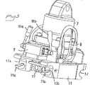
図4では、係止プランジャ14a,14bが押し込まれた中立の状態で工具保持具を斜め下方から示している。各係止プランジャは、H字状をなすヨーク15に取付けられている。ヨーク15は、2つの流体圧シリンダ16a,16bによって操作される。作動状態にあっては、ヨーク15が同図の右側斜め上方に移動され、前記係止プランジャが、図3に示す係止位置に向かって外方に移動される。更に、ヨーク15には、継手ランプ17が装着されている。その継手ランプには、流体ライン(図示せず)を介して流体圧式動力源に連結される雌型の継手ユニットが設けられている。この雌型継手ユニットは、工具ゲート3aの雄型の継手ユニットに連結されるように配置されている。係止プランジャがヨーク15を介し係止位置に移動することで工具の係止が実施される。それと同時に、継手ランプ17は、その継手ユニットを工具ゲート3aの工具ユニットに設けられた継手ユニットに連結させる位置にまで移動される。
図5には、工具を係止するため上記流体圧機構が連結されたときの流体圧の状態が示されている。弁板9には、2つの切替弁9a,9bが設けられている。各弁の入力側は、流体圧式動力源5からの各流体ライン24a,24bに対してそれぞれ連結されている。各弁9a,9bは、その出力側を流体継手ユニット17a,17b及び流体圧シリンダ16a,16bのいずれか一方に連結するため異なる2つの位置に切替え可能となっている。図5に示す位置では、流体ライン24a,24bが流体圧シリンダ16a,16bに対してそれぞれ連結されている。工具保持具2及び工具が上述されたような正確な位置に配置されているとき、流体ライン24aが加圧される。その結果、弁9a及び流体圧シリンダライン25aを介してプランジャ18a,18bが図5の上方に移動されることに伴って、係止プランジャ14a,14bを係止位置に突出させると共に、図4を参照して説明したように継手ランプ17の継手ユニット17a,17bを工具ゲート3aに設けられた継手ランプの継手ユニット20a,20bにそれぞれ連結させる。
図2は本発明に係る工具保持具を非係止状態で側方から見たときの斜視図。
図3は工具保持具を係止状態で図2と同じ方向から見たときの斜視図。
図5は図2〜図4に示す工具保持具のための流体圧機構の回路図。
図6は弁が別の位置に配置されているときの流体圧機構の回路図。
Claims (7)
- クレーン用工具のための工具保持具であって、
工具保持具(2)に対して工具(3)を取外し可能に係止するように設けられた流体圧シリンダ手段(16a,16b)と、
前記工具の流体継手手段(20a,20b)と連結するように設けられた流体継手手段(17a,17b)と、
流体ライン手段(24a,24b)とを備える工具保持具において、
前記工具保持具(2)は、切替手段(10a,10b)を有する弁手段(9)を更に備え、前記弁手段は、前記流体ライン手段(24a,24b)を前記流体圧シリンダ手段(16a,16b)及び前記工具保持具(2)の流体継手手段(17a,17b)のいずれか一方に連結するように設けられ、
前記各流体継手ユニット(17a,17b)は、流体継手ライン(26a,26b)により前記弁手段(9)に連結され、
前記各流体圧シリンダ(16a,16b)は、少なくとも1つの流体圧シリンダライン(25a,25b)により前記弁手段(9)に連結され、
前記各流体継手ライン(26a,26b)と前記流体圧シリンダラインの1つ(25a)との間には、連結ライン(19a,19b)が設けられ、
前記各連結ライン(19a,19b)には、逆止弁(22a,22b)が設けられ、
前記逆止弁(22a,22b)は、前記各流体継手ライン(26a,26b)から前記流体圧シリンダライン(25a)への流れを許容する一方、それとは逆向きの流れを禁止するように配向されていることを特徴とする工具保持具。 - 請求項1に記載の工具保持具において、
前記流体圧シリンダ手段(16a,16b)は2つの複動式流体圧シリンダ(16a,16b)を備えていることを特徴とする工具保持具。 - 請求項1又は2に記載の工具保持具において、
前記流体継手手段(17a,17b)は少なくとも2つの継手ユニット(17a,17b)を備え、前記流体ライン手段(24a,24b)は少なくとも2つの流体ライン(24a,24b)を備えていることを特徴とする工具保持具。 - 請求項1〜3のうちいずれか一項に記載の工具保持具において、
前記切替手段(10a,10b)は、前記弁手段(9)の連結を手動で切替えるために設けられていることを特徴とする工具保持具。 - 請求項1〜4のうちいずれか一項に記載の工具保持具において、
前記切替手段には、前記弁手段(9)の連結を切替えるための遠隔制御式の駆動手段が設けられていることを特徴とする工具保持具。 - 請求項1〜5のうちいずれか一項に記載の工具保持具を備えたクレーン。
- 工具を前記工具保持具に連結するための請求項1〜5のうちいずれか一項に記載の工具保持具の使用方法。
Applications Claiming Priority (2)
| Application Number | Priority Date | Filing Date | Title |
|---|---|---|---|
| SE0300229A SE524668C2 (sv) | 2003-01-30 | 2003-01-30 | Redskapsfäste med omkopplingsorgan |
| PCT/SE2004/000117 WO2004067855A1 (en) | 2003-01-30 | 2004-01-29 | Tool holder with hydraulic coupling means |
Publications (2)
| Publication Number | Publication Date |
|---|---|
| JP2006516522A JP2006516522A (ja) | 2006-07-06 |
| JP4543032B2 true JP4543032B2 (ja) | 2010-09-15 |
Family
ID=20290250
Family Applications (1)
| Application Number | Title | Priority Date | Filing Date |
|---|---|---|---|
| JP2006502784A Expired - Lifetime JP4543032B2 (ja) | 2003-01-30 | 2004-01-29 | 流体継手手段を備えた工具保持具 |
Country Status (11)
| Country | Link |
|---|---|
| US (1) | US7654787B2 (ja) |
| EP (1) | EP1595032B1 (ja) |
| JP (1) | JP4543032B2 (ja) |
| AT (1) | ATE548515T1 (ja) |
| AU (1) | AU2004208089B2 (ja) |
| CA (1) | CA2514722C (ja) |
| DK (1) | DK1595032T3 (ja) |
| ES (1) | ES2381787T3 (ja) |
| NO (1) | NO331628B1 (ja) |
| SE (1) | SE524668C2 (ja) |
| WO (1) | WO2004067855A1 (ja) |
Families Citing this family (12)
| Publication number | Priority date | Publication date | Assignee | Title |
|---|---|---|---|---|
| AT8623U3 (de) * | 2006-03-27 | 2007-04-15 | Baumaschinentechnik Ges M B H | Vorrichtung zum befestigen von anbaugeräten |
| SE529871C2 (sv) * | 2006-05-10 | 2007-12-18 | Oilquick Ab | Ventilblock, redskapsfäste och arbetsmaskin, samt användning av ett ventilblock |
| EP2426267B1 (en) | 2010-09-07 | 2020-12-30 | Caterpillar Work Tools B. V. | A coupling arrangement |
| EP2426266B1 (en) * | 2010-09-07 | 2018-10-17 | Caterpillar Work Tools B. V. | A coupling arrangement |
| SE536309C2 (sv) * | 2011-08-18 | 2013-08-13 | Verktygsfäste för skogsmaskin | |
| US9222235B2 (en) * | 2013-04-30 | 2015-12-29 | Ami Attachments Inc. | Coupler-assembly for attaching bucket or the like to articulating arm |
| SE539425C2 (sv) | 2014-09-03 | 2017-09-19 | Ytf Sweden Ab | Snabbkoppling för fastkoppling av ett hydraulmanövrerat verktyg/redskap på en grävmaskin |
| DE102014116245B4 (de) * | 2014-11-07 | 2016-11-10 | Bela Cseri | Schnellwechseleinrichtung einer Arbeitsmaschine |
| DE102014017550A1 (de) * | 2014-11-28 | 2016-06-02 | Axzion Gks Stahl Und Maschinenbau Gmbh | Adapter für Lastaufnahmeeinrichtungen |
| US10995469B1 (en) * | 2017-04-04 | 2021-05-04 | TAG Manufacturing, Inc. | Quick coupler |
| USD868845S1 (en) * | 2017-05-10 | 2019-12-03 | Oilquick Ab | Safety hooks for construction machinery |
| US11053660B2 (en) * | 2019-06-17 | 2021-07-06 | Caterpillar Inc. | Coupling assembly and method of hydraulically coupling to a tool |
Family Cites Families (17)
| Publication number | Priority date | Publication date | Assignee | Title |
|---|---|---|---|---|
| US3243066A (en) * | 1964-01-20 | 1966-03-29 | Caterpillar Tractor Co | Quick change means for loader attachments |
| US3873133A (en) * | 1972-08-25 | 1975-03-25 | Caterpillar Tractor Co | Clamshell bucket assembly for hydraulic excavator |
| DE2511819C3 (de) | 1975-03-18 | 1978-10-19 | Liebherr-Hydraulikbagger Gmbh, 7951 Kirchdorf | Hydraulikbagger |
| CA1106733A (en) * | 1977-07-13 | 1981-08-11 | Clark Equipment Company | Pressure control mechanism for a grapple skidder |
| US4208163A (en) * | 1978-01-18 | 1980-06-17 | Renholmens Mekaniska Verkstad Ab | Automatic quick-coupling device |
| US4280783A (en) * | 1979-04-10 | 1981-07-28 | Hayward John A D | Lost motion linkage assembly for a front loader |
| GB8625778D0 (en) * | 1986-10-28 | 1986-12-03 | Knackstedt J S | Connector |
| JPH045569Y2 (ja) * | 1987-06-10 | 1992-02-17 | ||
| US5049027A (en) * | 1990-02-21 | 1991-09-17 | Komatsu Dresser Company | Hydro-electric tool lock |
| GB9005074D0 (en) | 1990-03-07 | 1990-05-02 | Aubrey Martin J | Coupling |
| JPH0739969Y2 (ja) * | 1991-05-30 | 1995-09-13 | オカダアイヨン株式会社 | 作業機具取付装置 |
| JP2756078B2 (ja) * | 1993-12-16 | 1998-05-25 | 博 小野寺 | アタッチメント用カプラ |
| SE504450C2 (sv) * | 1996-02-19 | 1997-02-17 | Kavlugnt Ab | Kopplingsanordning för sammankoppling av ett arbetsredskap till en arbetsmaskin; både mekanisk hopkoppling och snabbkoppling av hydraullikkopplingarna |
| US5727342A (en) * | 1996-04-18 | 1998-03-17 | Wain-Roy, Inc. | Hydraulic latch pin assembly for coupling a tool to a construction equipment |
| JPH11181819A (ja) * | 1997-12-18 | 1999-07-06 | Komatsu Ltd | カプラの油圧保持装置 |
| FR2776316B1 (fr) * | 1998-03-18 | 2000-06-16 | Mailleux Sa | Systeme de verrouillage hydraulique d'un outil de chargeur |
| GB2335649B (en) * | 1998-03-27 | 2001-08-29 | Caterpillar Inc | A hydraulic control for a quick coupler |
-
2003
- 2003-01-30 SE SE0300229A patent/SE524668C2/sv not_active IP Right Cessation
-
2004
- 2004-01-29 AT AT04706407T patent/ATE548515T1/de active
- 2004-01-29 ES ES04706407T patent/ES2381787T3/es not_active Expired - Lifetime
- 2004-01-29 EP EP04706407A patent/EP1595032B1/en not_active Expired - Lifetime
- 2004-01-29 CA CA2514722A patent/CA2514722C/en not_active Expired - Lifetime
- 2004-01-29 JP JP2006502784A patent/JP4543032B2/ja not_active Expired - Lifetime
- 2004-01-29 DK DK04706407.6T patent/DK1595032T3/da active
- 2004-01-29 AU AU2004208089A patent/AU2004208089B2/en not_active Expired
- 2004-01-29 US US10/543,690 patent/US7654787B2/en active Active
- 2004-01-29 WO PCT/SE2004/000117 patent/WO2004067855A1/en active Application Filing
-
2005
- 2005-08-29 NO NO20053996A patent/NO331628B1/no not_active IP Right Cessation
Also Published As
| Publication number | Publication date |
|---|---|
| EP1595032B1 (en) | 2012-03-07 |
| SE524668C2 (sv) | 2004-09-14 |
| ES2381787T3 (es) | 2012-05-31 |
| AU2004208089B2 (en) | 2009-05-07 |
| ATE548515T1 (de) | 2012-03-15 |
| JP2006516522A (ja) | 2006-07-06 |
| CA2514722A1 (en) | 2004-08-12 |
| NO20053996L (no) | 2005-08-29 |
| NO331628B1 (no) | 2012-02-13 |
| US7654787B2 (en) | 2010-02-02 |
| DK1595032T3 (da) | 2012-04-16 |
| EP1595032A1 (en) | 2005-11-16 |
| CA2514722C (en) | 2013-05-14 |
| US20060101953A1 (en) | 2006-05-18 |
| SE0300229L (sv) | 2004-07-31 |
| WO2004067855A1 (en) | 2004-08-12 |
| AU2004208089A1 (en) | 2004-08-12 |
| SE0300229D0 (sv) | 2003-01-30 |
| NO20053996D0 (no) | 2005-08-29 |
Similar Documents
| Publication | Publication Date | Title |
|---|---|---|
| JP4543032B2 (ja) | 流体継手手段を備えた工具保持具 | |
| US6799424B2 (en) | Hydraulic circuit | |
| JP2010047421A (ja) | 掘削及びパイプレイング作業のための流量分配システム | |
| JP6214327B2 (ja) | ハイブリッド式建設機械 | |
| JP2005214327A (ja) | 油圧モータのブレーキ装置 | |
| JPH07166571A (ja) | アタッチメント用カプラ | |
| JP2010143727A (ja) | 建設機械の干渉防止装置 | |
| JP4166027B2 (ja) | 作業機の操作装置 | |
| KR20090069376A (ko) | 중장비용 카운터 웨이트의 탈부착장치 | |
| JP2006214111A (ja) | 作業機 | |
| KR102229132B1 (ko) | 카고크레인 장치 | |
| KR101542545B1 (ko) | 암대 설치형 집게를 구비하는 굴삭기용 유압장치 | |
| WO2023188593A1 (ja) | 建設機械 | |
| JP3326116B2 (ja) | ロープウインチの制御装置 | |
| JP2004091142A (ja) | クレーン | |
| KR102508403B1 (ko) | 크레인의 보조붐 설치장치 및 이를 이용한 보조붐 설치방법 | |
| JPH06294149A (ja) | 油圧ショベルの油圧駆動装置 | |
| JP4291443B2 (ja) | クレーン用油圧装置 | |
| JP2006169886A (ja) | 建設機械 | |
| JPH07158373A (ja) | アースドリルの油圧回路 | |
| JPH0827833A (ja) | クレーン付バックホー | |
| RU2055126C1 (ru) | Строительная машина с поворотной платформой | |
| KR20120069866A (ko) | 중장비의 메인컨트롤밸브 배치구조 | |
| KR970011209A (ko) | 다기능 복합 건설중장비 | |
| JP2006300105A (ja) | 作業機の油圧装置 |
Legal Events
| Date | Code | Title | Description |
|---|---|---|---|
| A621 | Written request for application examination |
Free format text: JAPANESE INTERMEDIATE CODE: A621 Effective date: 20061017 |
|
| A131 | Notification of reasons for refusal |
Free format text: JAPANESE INTERMEDIATE CODE: A131 Effective date: 20090929 |
|
| A601 | Written request for extension of time |
Free format text: JAPANESE INTERMEDIATE CODE: A601 Effective date: 20091218 |
|
| A602 | Written permission of extension of time |
Free format text: JAPANESE INTERMEDIATE CODE: A602 Effective date: 20091228 |
|
| A521 | Request for written amendment filed |
Free format text: JAPANESE INTERMEDIATE CODE: A523 Effective date: 20100129 |
|
| TRDD | Decision of grant or rejection written | ||
| A01 | Written decision to grant a patent or to grant a registration (utility model) |
Free format text: JAPANESE INTERMEDIATE CODE: A01 Effective date: 20100601 |
|
| A01 | Written decision to grant a patent or to grant a registration (utility model) |
Free format text: JAPANESE INTERMEDIATE CODE: A01 |
|
| A61 | First payment of annual fees (during grant procedure) |
Free format text: JAPANESE INTERMEDIATE CODE: A61 Effective date: 20100628 |
|
| R150 | Certificate of patent or registration of utility model |
Free format text: JAPANESE INTERMEDIATE CODE: R150 Ref document number: 4543032 Country of ref document: JP Free format text: JAPANESE INTERMEDIATE CODE: R150 |
|
| FPAY | Renewal fee payment (event date is renewal date of database) |
Free format text: PAYMENT UNTIL: 20130702 Year of fee payment: 3 |
|
| R250 | Receipt of annual fees |
Free format text: JAPANESE INTERMEDIATE CODE: R250 |
|
| R250 | Receipt of annual fees |
Free format text: JAPANESE INTERMEDIATE CODE: R250 |
|
| R250 | Receipt of annual fees |
Free format text: JAPANESE INTERMEDIATE CODE: R250 |
|
| R250 | Receipt of annual fees |
Free format text: JAPANESE INTERMEDIATE CODE: R250 |
|
| R250 | Receipt of annual fees |
Free format text: JAPANESE INTERMEDIATE CODE: R250 |
|
| R250 | Receipt of annual fees |
Free format text: JAPANESE INTERMEDIATE CODE: R250 |
|
| R250 | Receipt of annual fees |
Free format text: JAPANESE INTERMEDIATE CODE: R250 |
|
| R250 | Receipt of annual fees |
Free format text: JAPANESE INTERMEDIATE CODE: R250 |
|
| R250 | Receipt of annual fees |
Free format text: JAPANESE INTERMEDIATE CODE: R250 |
|
| R250 | Receipt of annual fees |
Free format text: JAPANESE INTERMEDIATE CODE: R250 |
|
| R250 | Receipt of annual fees |
Free format text: JAPANESE INTERMEDIATE CODE: R250 |