JP4543032B2 - Tool holder with fluid coupling means - Google Patents
Tool holder with fluid coupling means Download PDFInfo
- Publication number
- JP4543032B2 JP4543032B2 JP2006502784A JP2006502784A JP4543032B2 JP 4543032 B2 JP4543032 B2 JP 4543032B2 JP 2006502784 A JP2006502784 A JP 2006502784A JP 2006502784 A JP2006502784 A JP 2006502784A JP 4543032 B2 JP4543032 B2 JP 4543032B2
- Authority
- JP
- Japan
- Prior art keywords
- tool holder
- tool
- fluid
- fluid pressure
- line
- Prior art date
- Legal status (The legal status is an assumption and is not a legal conclusion. Google has not performed a legal analysis and makes no representation as to the accuracy of the status listed.)
- Expired - Lifetime
Links
- 230000008878 coupling Effects 0.000 title claims abstract description 32
- 238000010168 coupling process Methods 0.000 title claims abstract description 32
- 238000005859 coupling reaction Methods 0.000 title claims abstract description 32
- 239000012530 fluid Substances 0.000 title claims description 97
- 238000000034 method Methods 0.000 claims description 3
- 230000007246 mechanism Effects 0.000 description 15
- 238000010586 diagram Methods 0.000 description 3
- 230000008859 change Effects 0.000 description 2
- 230000007935 neutral effect Effects 0.000 description 2
- WKBPZYKAUNRMKP-UHFFFAOYSA-N 1-[2-(2,4-dichlorophenyl)pentyl]1,2,4-triazole Chemical compound C=1C=C(Cl)C=C(Cl)C=1C(CCC)CN1C=NC=N1 WKBPZYKAUNRMKP-UHFFFAOYSA-N 0.000 description 1
- 238000010276 construction Methods 0.000 description 1
- 238000011109 contamination Methods 0.000 description 1
- 230000001419 dependent effect Effects 0.000 description 1
- 238000005553 drilling Methods 0.000 description 1
- 239000000463 material Substances 0.000 description 1
- 239000013589 supplement Substances 0.000 description 1
Images


Classifications
-
- E—FIXED CONSTRUCTIONS
- E02—HYDRAULIC ENGINEERING; FOUNDATIONS; SOIL SHIFTING
- E02F—DREDGING; SOIL-SHIFTING
- E02F3/00—Dredgers; Soil-shifting machines
- E02F3/04—Dredgers; Soil-shifting machines mechanically-driven
- E02F3/28—Dredgers; Soil-shifting machines mechanically-driven with digging tools mounted on a dipper- or bucket-arm, i.e. there is either one arm or a pair of arms, e.g. dippers, buckets
- E02F3/36—Component parts
- E02F3/3604—Devices to connect tools to arms, booms or the like
- E02F3/3609—Devices to connect tools to arms, booms or the like of the quick acting type, e.g. controlled from the operator seat
- E02F3/3627—Devices to connect tools to arms, booms or the like of the quick acting type, e.g. controlled from the operator seat with a hook and a longitudinal locking element
-
- B—PERFORMING OPERATIONS; TRANSPORTING
- B66—HOISTING; LIFTING; HAULING
- B66C—CRANES; LOAD-ENGAGING ELEMENTS OR DEVICES FOR CRANES, CAPSTANS, WINCHES, OR TACKLES
- B66C3/00—Load-engaging elements or devices attached to lifting or lowering gear of cranes or adapted for connection therewith and intended primarily for transmitting lifting forces to loose materials; Grabs
- B66C3/005—Grab supports, e.g. articulations; Oscillation dampers; Orientation
-
- E—FIXED CONSTRUCTIONS
- E02—HYDRAULIC ENGINEERING; FOUNDATIONS; SOIL SHIFTING
- E02F—DREDGING; SOIL-SHIFTING
- E02F3/00—Dredgers; Soil-shifting machines
- E02F3/04—Dredgers; Soil-shifting machines mechanically-driven
- E02F3/28—Dredgers; Soil-shifting machines mechanically-driven with digging tools mounted on a dipper- or bucket-arm, i.e. there is either one arm or a pair of arms, e.g. dippers, buckets
- E02F3/36—Component parts
- E02F3/3604—Devices to connect tools to arms, booms or the like
- E02F3/3609—Devices to connect tools to arms, booms or the like of the quick acting type, e.g. controlled from the operator seat
- E02F3/3654—Devices to connect tools to arms, booms or the like of the quick acting type, e.g. controlled from the operator seat with energy coupler, e.g. coupler for hydraulic or electric lines, to provide energy to drive(s) mounted on the tool
-
- E—FIXED CONSTRUCTIONS
- E02—HYDRAULIC ENGINEERING; FOUNDATIONS; SOIL SHIFTING
- E02F—DREDGING; SOIL-SHIFTING
- E02F3/00—Dredgers; Soil-shifting machines
- E02F3/04—Dredgers; Soil-shifting machines mechanically-driven
- E02F3/28—Dredgers; Soil-shifting machines mechanically-driven with digging tools mounted on a dipper- or bucket-arm, i.e. there is either one arm or a pair of arms, e.g. dippers, buckets
- E02F3/36—Component parts
- E02F3/3604—Devices to connect tools to arms, booms or the like
- E02F3/3609—Devices to connect tools to arms, booms or the like of the quick acting type, e.g. controlled from the operator seat
- E02F3/3663—Devices to connect tools to arms, booms or the like of the quick acting type, e.g. controlled from the operator seat hydraulically-operated
Landscapes
- Engineering & Computer Science (AREA)
- Mechanical Engineering (AREA)
- Mining & Mineral Resources (AREA)
- Civil Engineering (AREA)
- General Engineering & Computer Science (AREA)
- Structural Engineering (AREA)
- Jib Cranes (AREA)
- Load-Engaging Elements For Cranes (AREA)
- Gripping Jigs, Holding Jigs, And Positioning Jigs (AREA)
- Fluid-Pressure Circuits (AREA)
- Auxiliary Devices For Machine Tools (AREA)
- Forklifts And Lifting Vehicles (AREA)
Abstract
Description
本発明は、第1の態様において、工具をその保持具に対して取外し可能に係止するように設けられた流体圧シリンダ手段と、工具の流体継手部材と連結するように設けられた流体継手手段と、流体ライン手段とを備えるクレーン用工具のための工具保持具に関する。 In the first aspect, the present invention provides a fluid pressure cylinder means provided to detachably lock the tool with respect to its holder, and a fluid coupling provided to connect with a fluid coupling member of the tool. A tool holder for a crane tool comprising means and fluid line means.
本発明は、第2の態様において、本発明の工具保持具を備えたクレーンに関し、第3の態様において、本発明の工具保持具の使用方法に関する。 In a second aspect, the present invention relates to a crane provided with the tool holder of the present invention. In a third aspect, the present invention relates to a method of using the tool holder of the present invention.
この種の工具保持具は、例えば掘削機、ホイールローダ、材料の搬送装置、及び同種の機械等、建築請負業者が所有する様々な機械においても使用されている。例えばクレーン車等で用いられるクレーン用工具保持具の面倒な問題として、工具が振り子状に懸吊され、工具保持具に流体圧式の回転装置が設けられていることがある。そのような回転装置は、材木把持装置、クラムシェルバケット、パレットフォーク、及び他の類似した工具において必要とされる。 This type of tool holder is also used in various machines owned by construction contractors, such as excavators, wheel loaders, material transporters, and similar machines. For example, a troublesome problem with a crane tool holder used in a crane truck or the like is that the tool is suspended in a pendulum shape, and the tool holder is provided with a fluid pressure type rotating device. Such a rotating device is required in timber gripping devices, clamshell buckets, pallet forks, and other similar tools.
従来のクレーン用工具保持具では、工具の流体圧による操作や工具保持具を係止する機構の操作のため、流体ラインが工具保持具に向かって延びている。係止機構が1又は複数の複動式流体圧シリンダを備えるため、通常は2本の流体ラインが前記係止の機能のために延びている。工具の操作のため2本又はそれ以上の流体ラインを備えるのであれば、少なくとも4本の流体ラインが工具保持具に向かって延びていることを意味する。このことは、相対的に複雑化し、それ故に高価なものになることを示唆する。一方、流体ラインをクレーンジブの全体に亘り上方に延長しなければならず、そのため、複数のクレーンジブを突出させているクレーン車についてはより一層厄介なものとなる。他方、多くのクレーンが回転装置を備えるという理由から、通常は一対の旋回式索道器のみを有している。係止機構の操作のため、2つの旋回式索道器が更に必要とされる。この場合、回転装置の回転台には4つのコイル導管を設ける必要があることを意味し、複雑化と価格の増大とを示唆する。 In a conventional crane tool holder, a fluid line extends toward the tool holder for operation by the fluid pressure of the tool or operation of a mechanism for locking the tool holder. Since the locking mechanism comprises one or more double-acting hydraulic cylinders, typically two fluid lines extend for the locking function. If two or more fluid lines are provided for the operation of the tool, it means that at least four fluid lines extend towards the tool holder. This suggests that it is relatively complex and therefore expensive. On the other hand, the fluid line must be extended upwardly over the entire crane jib, which makes it more troublesome for a crane vehicle with a plurality of crane jibs protruding. On the other hand, because many cranes are equipped with a rotating device, they usually have only a pair of swiveling cords. Two additional swiveling cords are further required for operation of the locking mechanism. In this case, it means that it is necessary to provide four coil conduits on the turntable of the rotating device, which suggests complexity and increased price.
この種の工具保持具として、OQ60と称するシステムにてオイルクイックアーベー社製のものや、トパスと称するシステムにてリープヘル社製のものが挙げられる。
更に、HEVOパーツアーベー社製の工具保持具が従来より公知であり、この場合、流体ホースの問題が様々な方法によって対処されている。この点について、流体圧シリンダが工具保持具に一体化され、同保持具が工具シリンダとしての機能も果たしている。このように回転装置の下で既存の流体圧の機能を利用することにより、例えばクラムシェルバケットやパレットフォークによる操作においてホースの連結が不要となる。しかしながら、穴掘り機や振動タンパ等のあらゆる種類の流体圧式工具では、従来のように流体ホースを手で連結する必要がある。ライン内の背圧やよくある油汚れのため、流体ホースを相互に手で連結することは度々問題を伴う。前記保持具の欠点は、特別に適合された工具しかその保持具と連結して使用することができないことにある。また、同保持具の大きさや重量も欠点として経験上知られている。保持具は機械式の係止機構を有し、同係止機構は、その場で操作者により手動で操作される。この保持具によって、流体ホースの問題の一部が解決される。
Examples of this type of tool holder include those manufactured by Oil Quick Arvey Co., Ltd. in a system called OQ60, and those manufactured by Liebherr Co., Ltd. in a system called Topas.
Furthermore, tool holders made by HEVO Pertour Bay are known in the prior art, in which the problem of fluid hoses has been addressed in various ways. In this regard, the fluid pressure cylinder is integrated with the tool holder, and the holder also functions as a tool cylinder. By utilizing the existing fluid pressure function under the rotating device in this way, it is not necessary to connect the hose in an operation using a clamshell bucket or a pallet fork, for example. However, in all types of hydraulic tools such as drilling machines and vibration tampers, it is necessary to manually connect the fluid hoses as in the prior art. Due to back pressure in the line and common oil contamination, it is often problematic to manually connect the fluid hoses together. The disadvantage of the holder is that only specially adapted tools can be used in connection with the holder. Further, the size and weight of the holder are also known from experience. The holder has a mechanical locking mechanism, and the locking mechanism is manually operated by an operator on the spot. This retainer solves some of the fluid hose problems.
本発明の目的は、問題となる種の工具保持具であって、従来より公知である種の工具保持具に関連する欠点を解消することにある。 The object of the present invention is to eliminate the disadvantages associated with the types of tool holders in question that are known in the art.
提示した目的は、本発明によれば、請求項1の前提部分で定義される種の工具保持具が特別な特徴を有するという事実によって達成される。その特徴とは、工具保持具は、切替手段を有する弁手段を備え、同弁手段は、流体ライン手段を流体圧シリンダ手段及び工具保持具の流体継手手段のいずれか一方に連結するように設けられている、ということである。 The object presented is achieved according to the invention by the fact that a tool holder of the kind defined in the preamble of claim 1 has special features. The tool holder includes valve means having switching means, and the valve means is provided to connect the fluid line means to either one of the hydraulic cylinder means and the fluid coupling means of the tool holder. It is that it is.
前記切替可能な弁手段によって、工具保持具に向かって延びる流体ラインは、係止機構の操作と、工具の操作との2つの目的を果たすことが可能になる。よって、流体ライン手段について必要とされる流体ラインの数が削減され、例えば、ラインの数を4本から2本に削減することができる。これにより、クレーンジブに沿って延びる流体ラインの長さが短くなると共に旋回式索道器の数が削減される。その結果、構造がより簡素化され、それゆえに一層安価なものになる。 The switchable valve means allows the fluid line extending towards the tool holder to serve two purposes: operation of the locking mechanism and operation of the tool. Therefore, the number of fluid lines required for the fluid line means is reduced, and for example, the number of lines can be reduced from four to two. This shortens the length of the fluid line extending along the crane jib and reduces the number of swiveling ropes. As a result, the structure is more simplified and therefore cheaper.
本発明による工具保持具では、最適なクレーン用保持具システム、特に保持具を装着するのに適しているクレーン車のための工具保持具システムを提供することが可能になる。言い換えれば、保持具は、
・機械式工具と流体圧式工具とを流体圧を通じて連結し、
・工具の流体圧機構に自動的に連結し、
・クレーンジブ及びクレーンのいずれにも流体圧を保持するための装置を追加する必要がなく、
・工具の流体圧の機能を保持具の係止機構の操作にも活用し、これらの機能が機械式又は遠隔制御式の切替えにより正しく行われ、
・操作が容易であり、かつ安全に行われ、
・重量を最小限に抑えると共に必要な容量(高さ及び幅)を最小限に抑えて、
・移動の間、設置しておくことが容易であり、
・市販されている多くの機械式工具及び流体圧式工具を利用することができ、
・一般的な回転装置の下で工具保持具が据付けられる。
The tool holder according to the invention makes it possible to provide an optimal crane holder system, in particular a tool holder system for a crane truck that is suitable for mounting the holder. In other words, the retainer
・ Connect mechanical tools and hydraulic tools through fluid pressure,
-Automatically connected to the fluid pressure mechanism of the tool,
・ There is no need to add a device to maintain fluid pressure in either the crane jib or the crane.
-The function of the fluid pressure of the tool is also used for the operation of the locking mechanism of the holder, and these functions are correctly performed by switching between mechanical and remote control types,
・ Easy to operate and safe
-Minimize weight and minimize required capacity (height and width)
・ Easy to install during movement,
・ Many commercially available mechanical tools and hydraulic tools can be used.
-The tool holder is installed under a general rotating device.
本発明の工具保持具の好ましい一実施形態によれば、シリンダ手段は2つの複動式流体圧シリンダを備えている。そのような流体圧シリンダは、本来であれば1つだけで十分かもしれない。しかしながら、係止が不安定になるか、或いは、2点で係止するため流体圧シリンダに分岐機構を設けて同係止の補助を行わなければならない。しかしながら、2つの流体圧シリンダを備えることで前記係止が一層簡素化される。2つよりも多くの流体圧シリンダを備えることは不要で、そのことが前記係止の位置を重複して決定してしまう虞もある。流体圧シリンダが複動式であるという点で、係止機能と解放機能とがそれぞれ円滑に実行される。 According to a preferred embodiment of the tool holder according to the invention, the cylinder means comprises two double-acting hydraulic cylinders. Only one such hydraulic cylinder may be sufficient in nature. However, the locking becomes unstable, or in order to lock at two points, a branching mechanism must be provided in the fluid pressure cylinder to assist the locking. However, the engagement is further simplified by providing two fluid pressure cylinders. It is unnecessary to provide more than two fluid pressure cylinders, and this may cause the position of the locking to be determined redundantly. The locking function and the releasing function are each smoothly executed in that the fluid pressure cylinder is double-acting.
他の好ましい一実施形態によれば、流体継手手段は、少なくとも2つの継手ユニットと、少なくとも2つの流体ラインを意味する流体ライン手段とを備えている。工具の操作では、多くの場合、1つよりも多くの流体ラインが必要とされている。このような理由から、この実施形態は好都合である。 According to another preferred embodiment, the fluid coupling means comprises at least two coupling units and fluid line means representing at least two fluid lines. Tool operation often requires more than one fluid line. For this reason, this embodiment is advantageous.
他の好ましい一実施形態によれば、各流体継手ユニットは流体継手ラインを通じて弁手段に連結され、各流体圧シリンダは少なくとも1つの流体圧シリンダラインを通じて弁手段に連結され、各流体継手ラインと流体圧シリンダラインの1つとの間には連結ラインが設けられ、各連結ラインには逆止弁が設けられ、その逆止弁は流体継手ラインから流体圧シリンダラインへの流れを許容する一方、それとは逆向きの流れを禁止するように配向されている。この実施形態で達成されるバイパス機能によって、係止操作後に流体ラインが工具の流体継手部材との連結のため切替えられたとき、係止位置にある流体圧シリンダ内の圧力が確実に維持される。従って、操作の間、簡素化された方法によって、工具が工具保持具に対して確実に係止される。 According to another preferred embodiment, each fluid coupling unit is connected to the valve means through a fluid coupling line, and each fluid pressure cylinder is connected to the valve means through at least one fluid pressure cylinder line. There is a connecting line between one of the pressure cylinder lines, and each connecting line is provided with a check valve, which allows flow from the fluid coupling line to the fluid pressure cylinder line, Are oriented to inhibit reverse flow. The bypass function achieved in this embodiment ensures that the pressure in the fluid pressure cylinder in the locked position is maintained when the fluid line is switched for connection with the fluid coupling member of the tool after the locking operation. . Thus, during operation, the tool is securely locked against the tool holder in a simplified manner.
他の好ましい一実施形態によれば、弁手段の連結を手動で切替えるための切替部材が設けられている。これは、弁手段の操作のためクレーンジブに沿って電気ケーブルを延長することが不要で、かつ簡素化された安全な切替えを意味している。 According to another preferred embodiment, a switching member for manually switching the connection of the valve means is provided. This means that it is not necessary to extend the electrical cable along the crane jib for the operation of the valve means, and means a simplified safe switching.
他の好ましい一実施形態によれば、切替手段には、前記弁手段の連結を切替えるための遠隔制御式の駆動手段が設けられている。この実施形態によれば、直前に記載された実施形態に対する補足又はそれとは別の形態を構成し、また、弁手段の切替時に操作者がその操作席を離れる必要が無い。 According to another preferred embodiment, the switching means is provided with a remote control type driving means for switching the connection of the valve means. According to this embodiment, a supplement to the embodiment described immediately before or another form is configured, and the operator does not have to leave the operation seat when switching the valve means.
上述したように、本発明の工具保持具の好ましい実施形態は請求項1に従属するいくつかの請求項により定義されている。
本発明によるクレーン及びその使用方法は、本発明の工具保持具及びその好ましい実施形態について上述されたものと同じような有利点を備えている。
As mentioned above, preferred embodiments of the tool holder according to the invention are defined by several claims dependent on claim 1.
The crane according to the invention and its method of use have the same advantages as described above for the tool holder of the invention and preferred embodiments thereof.
本発明を、以下の発明を実施するための最良の形態により添付図面を参照してより詳細に説明する。 The present invention will be described in more detail with reference to the accompanying drawings by the following best mode for carrying out the invention.
図1は、クレーン車に本発明が適用された例を示している。クレーンジブ1から工具保持具2が揺動するように懸吊され、工具3が工具保持具に対して係止されている。図示はしないが、流体ラインは、大型トラック4に搭載された流体圧式動力源5からクレーンジブ1に沿って延び、更に、工具保持具2に向かって下方に延びている。流体圧式動力源は、操作者により操作される操作ユニット6から制御される。
FIG. 1 shows an example in which the present invention is applied to a crane vehicle. The
工具3を工具保持具から取外し、他の種類の工具に交換することができる。本発明は、そのような工具の変更を最適な態様で行えるようにすることを目的としている。
図2〜図4には、工具保持具がより詳細に示されている。図2には、工具保持具が中立の状態で示されている。工具保持具2の頂部には回転装置7が設けられ、同回転装置7は、工具保持具の主要部8に対して回転可能である。工具保持具の下部は、同工具保持具の連結部11を構成すると共に、工具の工具ゲート3aとの連結、即ち工具保持具2に対して連結されるべく構成された工具3の一部と連結可能に形成されている。工具保持具2の連結部11は一方の側にU字状をなす2つの凹部12を有し、そのうちの1つの凹部のみが図に現れている。連結部11の反対側には、L字状をなす2つの外縁部13a,13bと、2つの係止プランジャ14a,14bとが設けられ、図2には、同係止プランジャが押し込まれた状態で示されている。係止プランジャは、上記したL字状の外縁部と共にU字状の外縁部を形成するため外部に突出可能となっている。
The tool 3 can be removed from the tool holder and replaced with another type of tool. An object of the present invention is to enable such a tool change in an optimum manner.
2 to 4 show the tool holder in more detail. FIG. 2 shows the tool holder in a neutral state. A
工具ゲート3aには2つのバー(図示せず)が設けられ、それらは、工具をその保持具に連結させるとき、凹部12及びL字状の外縁部13a,13bと協働するようにそれぞれ配置されている。工具が工具保持具に連結される場合、同工具保持具では、U字状の凹部が、工具ゲート3aの1本のバーに係合するように配置される。次に、工具ゲートの2本目のバーがL字状の外縁部の内側に配置されるまで、工具及び工具保持具は上記のバーの周辺で相互に旋回される。この位置で流体圧シリンダが作動し、その作動により形成されるU字状の外縁部の内側に第2のバーが配置されるように、係止プランジャ14a,14bを突出させる。同位置で、工具が工具保持具に対して係止される。更に、工具保持具の流体継手ユニットが工具の流体継手ユニットに連結される。本明細書に記載された連結のための一連の操作は現状の技術である。
The
本発明による工具保持具では、工具保持具に弁板9が装着されている。弁板9は、2つのレバー10a,10bによって操作することができる。これらによって、流体圧式動力源から工具保持具へと通じる流体ラインを、前記係止を操作する流体圧シリンダ及び工具の対応するユニットに連結される流体継手ユニットのいずれか一方に連結するように切替えられる。図2に示す状態では、係止プランジャ用の流体圧シリンダが作動されていない。これらは、各レバーを互いに向かって約15°旋回させることによって作動される。
In the tool holder according to the present invention, the
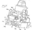
その作動された状態が図3に示されている。従って、同図では、係止プランジャ14a,14bが突出されている。
図4では、係止プランジャ14a,14bが押し込まれた中立の状態で工具保持具を斜め下方から示している。各係止プランジャは、H字状をなすヨーク15に取付けられている。ヨーク15は、2つの流体圧シリンダ16a,16bによって操作される。作動状態にあっては、ヨーク15が同図の右側斜め上方に移動され、前記係止プランジャが、図3に示す係止位置に向かって外方に移動される。更に、ヨーク15には、継手ランプ17が装着されている。その継手ランプには、流体ライン(図示せず)を介して流体圧式動力源に連結される雌型の継手ユニットが設けられている。この雌型継手ユニットは、工具ゲート3aの雄型の継手ユニットに連結されるように配置されている。係止プランジャがヨーク15を介し係止位置に移動することで工具の係止が実施される。それと同時に、継手ランプ17は、その継手ユニットを工具ゲート3aの工具ユニットに設けられた継手ユニットに連結させる位置にまで移動される。
The activated state is shown in FIG. Accordingly, in the same figure, the locking
In FIG. 4, the tool holder is shown obliquely from below in a neutral state in which the
本発明の原理は、図5及び図6に示す流体圧機構の回路図から最もよく理解される。
図5には、工具を係止するため上記流体圧機構が連結されたときの流体圧の状態が示されている。弁板9には、2つの切替弁9a,9bが設けられている。各弁の入力側は、流体圧式動力源5からの各流体ライン24a,24bに対してそれぞれ連結されている。各弁9a,9bは、その出力側を流体継手ユニット17a,17b及び流体圧シリンダ16a,16bのいずれか一方に連結するため異なる2つの位置に切替え可能となっている。図5に示す位置では、流体ライン24a,24bが流体圧シリンダ16a,16bに対してそれぞれ連結されている。工具保持具2及び工具が上述されたような正確な位置に配置されているとき、流体ライン24aが加圧される。その結果、弁9a及び流体圧シリンダライン25aを介してプランジャ18a,18bが図5の上方に移動されることに伴って、係止プランジャ14a,14bを係止位置に突出させると共に、図4を参照して説明したように継手ランプ17の継手ユニット17a,17bを工具ゲート3aに設けられた継手ランプの継手ユニット20a,20bにそれぞれ連結させる。
The principles of the present invention are best understood from the circuit diagrams of the fluid pressure mechanism shown in FIGS.
FIG. 5 shows the state of fluid pressure when the fluid pressure mechanism is connected to lock the tool. The
前記係止の段階が達成されたとき、弁9a,9bは、図6に示す位置に切替えられる。この時点で、係止プランジャは係止位置に配置されており、継手ランプ17の継手ユニット17a,17bは継手ランプ20の継手ユニット20a,20bにそれぞれ連結されている。この連結状態で、流体ライン24a,24bは、弁9a,9b、流体継手ライン26a,26b、及び継手ユニット17a,17b、20a,20bを介して工具の流体圧機構21a,21bにそれぞれ連結される。それにより、工具は操作可能な状態とされる。各流体継手ライン26a,26bには、係止時に加圧される流体圧シリンダライン25aに通じる連結ライン19a、19bがそれぞれ設けられている。各連結ライン19a,19bには、逆止弁22a、22bがそれぞれ設けられている。これらは、各流体継手ラインから前記流体圧シリンダラインへの流れを許容する一方、それとは逆向きの流れを禁止するように配向されている。それによって、流体圧シリンダ内の圧力が減衰する傾向にある場合、流体継手ライン26a,26bのいずれか一方から加圧された流体圧用の油が流体圧シリンダライン25a内に圧入されるため、操作中に各流体圧シリンダ16a,16bの加圧側での圧力が確実に維持される。つまり、このバイパス機能が係止保護を構成している。
When the locking stage is achieved, the
例えば工具の交換のため、工具保持具から工具が取外されるとき、弁が図5に示す位置に切替えられると共に、各流体圧シリンダ16a,16bの第2の側(図中上側)が加圧されることで係止プランジャが引込められる。同時に、継手ランプ17,20の連結が解除される。
For example, when the tool is removed from the tool holder to change the tool, the valve is switched to the position shown in FIG. 5 and the second side (upper side in the figure) of each
弁9a,9bの切替えは、図2〜図4に示すレバー10a,10bによって実施される。弁9a,9bが操作位置、即ち図6に示す位置に配置され、かつレバーが図3に示す位置に配置されているときに同レバーをロックするためのロック機構(図示せず)が設けられている。
Switching of the
レバー10a,10bにより手動で切替えることの別の選択肢として、弁の位置を移動させるためのバッテリ駆動式モータを弁板に接続した構成を採用してもよい。これは、無線遠隔制御によって適切に操作される。 As another option of switching manually by levers 10a and 10b, a configuration in which a battery-driven motor for moving the position of the valve is connected to the valve plate may be employed. This is properly operated by wireless remote control.
図1は発明に係る工具保持具を備えたクレーンを示す側面図。
図2は本発明に係る工具保持具を非係止状態で側方から見たときの斜視図。
図3は工具保持具を係止状態で図2と同じ方向から見たときの斜視図。
FIG. 1 is a side view showing a crane provided with a tool holder according to the invention.
FIG. 2 is a perspective view when the tool holder according to the present invention is viewed from the side in an unlocked state.
FIG. 3 is a perspective view when the tool holder is viewed from the same direction as FIG. 2 in a locked state.
図4は図2に示す工具保持具を非係止状態で斜め下方から見たときの斜視図。
図5は図2〜図4に示す工具保持具のための流体圧機構の回路図。
図6は弁が別の位置に配置されているときの流体圧機構の回路図。
FIG. 4 is a perspective view when the tool holder shown in FIG. 2 is viewed from obliquely below in an unlocked state.
FIG. 5 is a circuit diagram of a fluid pressure mechanism for the tool holder shown in FIGS.
FIG. 6 is a circuit diagram of the fluid pressure mechanism when the valve is disposed at another position.
Claims (7)
工具保持具(2)に対して工具(3)を取外し可能に係止するように設けられた流体圧シリンダ手段(16a,16b)と、
前記工具の流体継手手段(20a,20b)と連結するように設けられた流体継手手段(17a,17b)と、
流体ライン手段(24a,24b)とを備える工具保持具において、
前記工具保持具(2)は、切替手段(10a,10b)を有する弁手段(9)を更に備え、前記弁手段は、前記流体ライン手段(24a,24b)を前記流体圧シリンダ手段(16a,16b)及び前記工具保持具(2)の流体継手手段(17a,17b)のいずれか一方に連結するように設けられ、
前記各流体継手ユニット(17a,17b)は、流体継手ライン(26a,26b)により前記弁手段(9)に連結され、
前記各流体圧シリンダ(16a,16b)は、少なくとも1つの流体圧シリンダライン(25a,25b)により前記弁手段(9)に連結され、
前記各流体継手ライン(26a,26b)と前記流体圧シリンダラインの1つ(25a)との間には、連結ライン(19a,19b)が設けられ、
前記各連結ライン(19a,19b)には、逆止弁(22a,22b)が設けられ、
前記逆止弁(22a,22b)は、前記各流体継手ライン(26a,26b)から前記流体圧シリンダライン(25a)への流れを許容する一方、それとは逆向きの流れを禁止するように配向されていることを特徴とする工具保持具。A tool holder for a crane tool,
Fluid pressure cylinder means (16a, 16b) provided to detachably lock the tool (3) to the tool holder (2);
Fluid coupling means (17a, 17b) provided to connect with the fluid coupling means (20a, 20b) of the tool;
A tool holder comprising fluid line means (24a, 24b),
The tool holder (2), the switching means (10 a, 10b) further includes a valve means (9) having said valve means, said fluid line means (24a, 24b) of said hydraulic cylinder means (16a 16b) and the fluid coupling means (17a, 17b) of the tool holder (2) .
Each fluid coupling unit (17a, 17b) is connected to the valve means (9) by a fluid coupling line (26a, 26b),
Each fluid pressure cylinder (16a, 16b) is connected to the valve means (9) by at least one fluid pressure cylinder line (25a, 25b),
A connecting line (19a, 19b) is provided between each of the fluid coupling lines (26a, 26b) and one of the fluid pressure cylinder lines (25a),
Each connecting line (19a, 19b) is provided with a check valve (22a, 22b),
The check valves (22a, 22b) are oriented so as to allow the flow from the fluid coupling lines (26a, 26b) to the fluid pressure cylinder line (25a), but prohibit the flow in the opposite direction. A tool holder characterized by being made .
前記流体圧シリンダ手段(16a,16b)は2つの複動式流体圧シリンダ(16a,16b)を備えていることを特徴とする工具保持具。The tool holder according to claim 1,
The tool holder according to claim 1, wherein the fluid pressure cylinder means (16a, 16b) includes two double-acting fluid pressure cylinders (16a, 16b).
前記流体継手手段(17a,17b)は少なくとも2つの継手ユニット(17a,17b)を備え、前記流体ライン手段(24a,24b)は少なくとも2つの流体ライン(24a,24b)を備えていることを特徴とする工具保持具。The tool holder according to claim 1 or 2,
The fluid coupling means (17a, 17b) includes at least two coupling units (17a, 17b), and the fluid line means (24a, 24b) includes at least two fluid lines (24a, 24b). A tool holder.
前記切替手段(10a,10b)は、前記弁手段(9)の連結を手動で切替えるために設けられていることを特徴とする工具保持具。In the tool holder as described in any one of Claims 1-3 ,
The switch means (10a, 10b) is provided for manually switching the connection of the valve means (9).
前記切替手段には、前記弁手段(9)の連結を切替えるための遠隔制御式の駆動手段が設けられていることを特徴とする工具保持具。In the tool holder as described in any one of Claims 1-4 ,
A tool holder, wherein the switching means is provided with a remote control type driving means for switching the connection of the valve means (9).
Applications Claiming Priority (2)
| Application Number | Priority Date | Filing Date | Title |
|---|---|---|---|
| SE0300229A SE524668C2 (en) | 2003-01-30 | 2003-01-30 | Utility bracket with switching means |
| PCT/SE2004/000117 WO2004067855A1 (en) | 2003-01-30 | 2004-01-29 | Tool holder with hydraulic coupling means |
Publications (2)
| Publication Number | Publication Date |
|---|---|
| JP2006516522A JP2006516522A (en) | 2006-07-06 |
| JP4543032B2 true JP4543032B2 (en) | 2010-09-15 |
Family
ID=20290250
Family Applications (1)
| Application Number | Title | Priority Date | Filing Date |
|---|---|---|---|
| JP2006502784A Expired - Lifetime JP4543032B2 (en) | 2003-01-30 | 2004-01-29 | Tool holder with fluid coupling means |
Country Status (11)
| Country | Link |
|---|---|
| US (1) | US7654787B2 (en) |
| EP (1) | EP1595032B1 (en) |
| JP (1) | JP4543032B2 (en) |
| AT (1) | ATE548515T1 (en) |
| AU (1) | AU2004208089B2 (en) |
| CA (1) | CA2514722C (en) |
| DK (1) | DK1595032T3 (en) |
| ES (1) | ES2381787T3 (en) |
| NO (1) | NO331628B1 (en) |
| SE (1) | SE524668C2 (en) |
| WO (1) | WO2004067855A1 (en) |
Families Citing this family (13)
| Publication number | Priority date | Publication date | Assignee | Title |
|---|---|---|---|---|
| AT8623U3 (en) * | 2006-03-27 | 2007-04-15 | Baumaschinentechnik Ges M B H | DEVICE FOR MOUNTING ATTACHMENTS |
| SE529871C2 (en) * | 2006-05-10 | 2007-12-18 | Oilquick Ab | Valve block, tool bracket and work machine, and use of a valve block |
| EP2426267B1 (en) | 2010-09-07 | 2020-12-30 | Caterpillar Work Tools B. V. | A coupling arrangement |
| EP2426266B1 (en) * | 2010-09-07 | 2018-10-17 | Caterpillar Work Tools B. V. | A coupling arrangement |
| SE536309C2 (en) * | 2011-08-18 | 2013-08-13 | Tool holder for forest machine | |
| US9222235B2 (en) * | 2013-04-30 | 2015-12-29 | Ami Attachments Inc. | Coupler-assembly for attaching bucket or the like to articulating arm |
| SE539425C2 (en) | 2014-09-03 | 2017-09-19 | Ytf Sweden Ab | Quick coupler for attaching a hydraulically operated tool / implement to an excavator |
| DE102014116245B4 (en) * | 2014-11-07 | 2016-11-10 | Bela Cseri | Quick change device of a work machine |
| DE102014017550A1 (en) * | 2014-11-28 | 2016-06-02 | Axzion Gks Stahl Und Maschinenbau Gmbh | Adapter for load suspension devices |
| US10995469B1 (en) * | 2017-04-04 | 2021-05-04 | TAG Manufacturing, Inc. | Quick coupler |
| USD868845S1 (en) * | 2017-05-10 | 2019-12-03 | Oilquick Ab | Safety hooks for construction machinery |
| US11053660B2 (en) * | 2019-06-17 | 2021-07-06 | Caterpillar Inc. | Coupling assembly and method of hydraulically coupling to a tool |
| EP4400655A1 (en) | 2023-01-10 | 2024-07-17 | Oilquick AB | Tool holder for a machine with an improved safety system |
Family Cites Families (17)
| Publication number | Priority date | Publication date | Assignee | Title |
|---|---|---|---|---|
| US3243066A (en) * | 1964-01-20 | 1966-03-29 | Caterpillar Tractor Co | Quick change means for loader attachments |
| US3873133A (en) * | 1972-08-25 | 1975-03-25 | Caterpillar Tractor Co | Clamshell bucket assembly for hydraulic excavator |
| DE2511819C3 (en) * | 1975-03-18 | 1978-10-19 | Liebherr-Hydraulikbagger Gmbh, 7951 Kirchdorf | Hydraulic excavator |
| CA1106733A (en) | 1977-07-13 | 1981-08-11 | Clark Equipment Company | Pressure control mechanism for a grapple skidder |
| US4208163A (en) * | 1978-01-18 | 1980-06-17 | Renholmens Mekaniska Verkstad Ab | Automatic quick-coupling device |
| US4280783A (en) * | 1979-04-10 | 1981-07-28 | Hayward John A D | Lost motion linkage assembly for a front loader |
| GB8625778D0 (en) * | 1986-10-28 | 1986-12-03 | Knackstedt J S | Connector |
| JPH045569Y2 (en) * | 1987-06-10 | 1992-02-17 | ||
| US5049027A (en) | 1990-02-21 | 1991-09-17 | Komatsu Dresser Company | Hydro-electric tool lock |
| GB9005074D0 (en) | 1990-03-07 | 1990-05-02 | Aubrey Martin J | Coupling |
| JPH0739969Y2 (en) * | 1991-05-30 | 1995-09-13 | オカダアイヨン株式会社 | Work implement mounting device |
| JP2756078B2 (en) * | 1993-12-16 | 1998-05-25 | 博 小野寺 | Attachment coupler |
| SE504450C2 (en) * | 1996-02-19 | 1997-02-17 | Kavlugnt Ab | Coupling device for connecting a working tool to a working machine; both mechanical coupling and quick coupling of the hydraulic couplings |
| US5727342A (en) * | 1996-04-18 | 1998-03-17 | Wain-Roy, Inc. | Hydraulic latch pin assembly for coupling a tool to a construction equipment |
| JPH11181819A (en) * | 1997-12-18 | 1999-07-06 | Komatsu Ltd | Hydraulic retaining device for coupler |
| FR2776316B1 (en) | 1998-03-18 | 2000-06-16 | Mailleux Sa | HYDRAULIC LOCKING SYSTEM OF A LOADER TOOL |
| JP4447066B2 (en) * | 1998-03-27 | 2010-04-07 | キャタピラー インコーポレイテッド | Hydraulic control device for work implement installation |
-
2003
- 2003-01-30 SE SE0300229A patent/SE524668C2/en not_active IP Right Cessation
-
2004
- 2004-01-29 ES ES04706407T patent/ES2381787T3/en not_active Expired - Lifetime
- 2004-01-29 EP EP04706407A patent/EP1595032B1/en not_active Expired - Lifetime
- 2004-01-29 DK DK04706407.6T patent/DK1595032T3/en active
- 2004-01-29 CA CA2514722A patent/CA2514722C/en not_active Expired - Lifetime
- 2004-01-29 AU AU2004208089A patent/AU2004208089B2/en not_active Expired
- 2004-01-29 WO PCT/SE2004/000117 patent/WO2004067855A1/en active Application Filing
- 2004-01-29 US US10/543,690 patent/US7654787B2/en active Active
- 2004-01-29 AT AT04706407T patent/ATE548515T1/en active
- 2004-01-29 JP JP2006502784A patent/JP4543032B2/en not_active Expired - Lifetime
-
2005
- 2005-08-29 NO NO20053996A patent/NO331628B1/en not_active IP Right Cessation
Also Published As
| Publication number | Publication date |
|---|---|
| SE524668C2 (en) | 2004-09-14 |
| NO331628B1 (en) | 2012-02-13 |
| NO20053996L (en) | 2005-08-29 |
| US20060101953A1 (en) | 2006-05-18 |
| SE0300229L (en) | 2004-07-31 |
| ATE548515T1 (en) | 2012-03-15 |
| SE0300229D0 (en) | 2003-01-30 |
| AU2004208089A1 (en) | 2004-08-12 |
| CA2514722A1 (en) | 2004-08-12 |
| EP1595032A1 (en) | 2005-11-16 |
| DK1595032T3 (en) | 2012-04-16 |
| JP2006516522A (en) | 2006-07-06 |
| WO2004067855A1 (en) | 2004-08-12 |
| AU2004208089B2 (en) | 2009-05-07 |
| NO20053996D0 (en) | 2005-08-29 |
| US7654787B2 (en) | 2010-02-02 |
| ES2381787T3 (en) | 2012-05-31 |
| CA2514722C (en) | 2013-05-14 |
| EP1595032B1 (en) | 2012-03-07 |
Similar Documents
| Publication | Publication Date | Title |
|---|---|---|
| JP4543032B2 (en) | Tool holder with fluid coupling means | |
| US6799424B2 (en) | Hydraulic circuit | |
| JP2010047421A (en) | Flow distribution system for drilling and pipe-laying work | |
| JP6214327B2 (en) | Hybrid construction machine | |
| JP2005214327A (en) | Brake device of hydraulic motor | |
| JPH07166571A (en) | Coupler for attachment | |
| JP2010143727A (en) | Interference preventive device of construction machine | |
| JP4166027B2 (en) | Operating device for work equipment | |
| KR20090069376A (en) | Apparatus for removing and mounting a counter weight of heavy equipment | |
| JP2006214111A (en) | Working machine | |
| KR102229132B1 (en) | Apparatus for cargo crane | |
| JP7569472B2 (en) | Construction Machinery | |
| KR101542545B1 (en) | Hydraulic equipment for excavator having tongs installing arm | |
| JP3326116B2 (en) | Control device for rope winch | |
| JP2004091142A (en) | Crane | |
| KR102508403B1 (en) | Crane auxiliary boom installation apparatus and installation method using thereof | |
| JPH06294149A (en) | Hydraulic drive device for hydraulic shovel | |
| JP4291443B2 (en) | Hydraulic equipment for crane | |
| JP2006169886A (en) | Construction machine | |
| JPH07158373A (en) | Hydraulic circuit of earth drill | |
| JPH0827833A (en) | Back hoe with crane | |
| RU2055126C1 (en) | Swivel-platform machine | |
| KR970011209A (en) | Multifunction construction heavy equipment | |
| JP2006300105A (en) | Hydraulic device of work machine | |
| KR20080054958A (en) | Locking device for actuates of wheel loader |
Legal Events
| Date | Code | Title | Description |
|---|---|---|---|
| A621 | Written request for application examination |
Free format text: JAPANESE INTERMEDIATE CODE: A621 Effective date: 20061017 |
|
| A131 | Notification of reasons for refusal |
Free format text: JAPANESE INTERMEDIATE CODE: A131 Effective date: 20090929 |
|
| A601 | Written request for extension of time |
Free format text: JAPANESE INTERMEDIATE CODE: A601 Effective date: 20091218 |
|
| A602 | Written permission of extension of time |
Free format text: JAPANESE INTERMEDIATE CODE: A602 Effective date: 20091228 |
|
| A521 | Request for written amendment filed |
Free format text: JAPANESE INTERMEDIATE CODE: A523 Effective date: 20100129 |
|
| TRDD | Decision of grant or rejection written | ||
| A01 | Written decision to grant a patent or to grant a registration (utility model) |
Free format text: JAPANESE INTERMEDIATE CODE: A01 Effective date: 20100601 |
|
| A01 | Written decision to grant a patent or to grant a registration (utility model) |
Free format text: JAPANESE INTERMEDIATE CODE: A01 |
|
| A61 | First payment of annual fees (during grant procedure) |
Free format text: JAPANESE INTERMEDIATE CODE: A61 Effective date: 20100628 |
|
| R150 | Certificate of patent or registration of utility model |
Ref document number: 4543032 Country of ref document: JP Free format text: JAPANESE INTERMEDIATE CODE: R150 |
|
| FPAY | Renewal fee payment (event date is renewal date of database) |
Free format text: PAYMENT UNTIL: 20130702 Year of fee payment: 3 |
|
| R250 | Receipt of annual fees |
Free format text: JAPANESE INTERMEDIATE CODE: R250 |
|
| R250 | Receipt of annual fees |
Free format text: JAPANESE INTERMEDIATE CODE: R250 |
|
| R250 | Receipt of annual fees |
Free format text: JAPANESE INTERMEDIATE CODE: R250 |
|
| R250 | Receipt of annual fees |
Free format text: JAPANESE INTERMEDIATE CODE: R250 |
|
| R250 | Receipt of annual fees |
Free format text: JAPANESE INTERMEDIATE CODE: R250 |
|
| R250 | Receipt of annual fees |
Free format text: JAPANESE INTERMEDIATE CODE: R250 |
|
| R250 | Receipt of annual fees |
Free format text: JAPANESE INTERMEDIATE CODE: R250 |
|
| R250 | Receipt of annual fees |
Free format text: JAPANESE INTERMEDIATE CODE: R250 |
|
| R250 | Receipt of annual fees |
Free format text: JAPANESE INTERMEDIATE CODE: R250 |
|
| R250 | Receipt of annual fees |
Free format text: JAPANESE INTERMEDIATE CODE: R250 |
|
| R250 | Receipt of annual fees |
Free format text: JAPANESE INTERMEDIATE CODE: R250 |
|
| EXPY | Cancellation because of completion of term |