JP4027359B2 - マイクロ揺動体、光偏向器、画像形成装置 - Google Patents
マイクロ揺動体、光偏向器、画像形成装置 Download PDFInfo
- Publication number
- JP4027359B2 JP4027359B2 JP2004323758A JP2004323758A JP4027359B2 JP 4027359 B2 JP4027359 B2 JP 4027359B2 JP 2004323758 A JP2004323758 A JP 2004323758A JP 2004323758 A JP2004323758 A JP 2004323758A JP 4027359 B2 JP4027359 B2 JP 4027359B2
- Authority
- JP
- Japan
- Prior art keywords
- vibration mode
- mover
- frequency
- optical deflector
- micro
- Prior art date
- Legal status (The legal status is an assumption and is not a legal conclusion. Google has not performed a legal analysis and makes no representation as to the accuracy of the status listed.)
- Expired - Fee Related
Links
Images


Classifications
-
- G—PHYSICS
- G02—OPTICS
- G02B—OPTICAL ELEMENTS, SYSTEMS OR APPARATUS
- G02B26/00—Optical devices or arrangements for the control of light using movable or deformable optical elements
- G02B26/08—Optical devices or arrangements for the control of light using movable or deformable optical elements for controlling the direction of light
- G02B26/10—Scanning systems
- G02B26/105—Scanning systems with one or more pivoting mirrors or galvano-mirrors
-
- B—PERFORMING OPERATIONS; TRANSPORTING
- B81—MICROSTRUCTURAL TECHNOLOGY
- B81B—MICROSTRUCTURAL DEVICES OR SYSTEMS, e.g. MICROMECHANICAL DEVICES
- B81B3/00—Devices comprising flexible or deformable elements, e.g. comprising elastic tongues or membranes
-
- G—PHYSICS
- G02—OPTICS
- G02B—OPTICAL ELEMENTS, SYSTEMS OR APPARATUS
- G02B26/00—Optical devices or arrangements for the control of light using movable or deformable optical elements
- G02B26/08—Optical devices or arrangements for the control of light using movable or deformable optical elements for controlling the direction of light
- G02B26/0816—Optical devices or arrangements for the control of light using movable or deformable optical elements for controlling the direction of light by means of one or more reflecting elements
- G02B26/0833—Optical devices or arrangements for the control of light using movable or deformable optical elements for controlling the direction of light by means of one or more reflecting elements the reflecting element being a micromechanical device, e.g. a MEMS mirror, DMD
- G02B26/085—Optical devices or arrangements for the control of light using movable or deformable optical elements for controlling the direction of light by means of one or more reflecting elements the reflecting element being a micromechanical device, e.g. a MEMS mirror, DMD the reflecting means being moved or deformed by electromagnetic means
-
- G—PHYSICS
- G02—OPTICS
- G02B—OPTICAL ELEMENTS, SYSTEMS OR APPARATUS
- G02B26/00—Optical devices or arrangements for the control of light using movable or deformable optical elements
- G02B26/08—Optical devices or arrangements for the control of light using movable or deformable optical elements for controlling the direction of light
- G02B26/10—Scanning systems
-
- Y—GENERAL TAGGING OF NEW TECHNOLOGICAL DEVELOPMENTS; GENERAL TAGGING OF CROSS-SECTIONAL TECHNOLOGIES SPANNING OVER SEVERAL SECTIONS OF THE IPC; TECHNICAL SUBJECTS COVERED BY FORMER USPC CROSS-REFERENCE ART COLLECTIONS [XRACs] AND DIGESTS
- Y10—TECHNICAL SUBJECTS COVERED BY FORMER USPC
- Y10S—TECHNICAL SUBJECTS COVERED BY FORMER USPC CROSS-REFERENCE ART COLLECTIONS [XRACs] AND DIGESTS
- Y10S359/00—Optical: systems and elements
- Y10S359/904—Micromirror
Landscapes
- Physics & Mathematics (AREA)
- General Physics & Mathematics (AREA)
- Optics & Photonics (AREA)
- Electromagnetism (AREA)
- Engineering & Computer Science (AREA)
- Computer Hardware Design (AREA)
- Microelectronics & Electronic Packaging (AREA)
- Facsimile Scanning Arrangements (AREA)
- Mechanical Optical Scanning Systems (AREA)
- Micromachines (AREA)
- Mechanical Light Control Or Optical Switches (AREA)
Description
θ´=θ0ωcos(ωt) (数式2)
ただし、θ0:最大変位角、ω:角振動数である。このとき、
θ´max=θ0ω (数式3)
θ´min≦θ0ωcos(ωt) (数式4)
の関係が成立する。この様子を説明するのが図17である。図17において、t=0の前後で上式を満たす時間範囲は、
−cos−1(θ´min/θ0ω)≦ωt≦−cos−1(θ´min/θ0ω) (数式5)
の範囲であり、この条件を満たす使用可能最大振れ角θeffと、一周期のうち使用できる時間ある有効時間teffは、
θeff=θ0sin(cos−1(θ´min/θ´max)) (数式6)
teff=2cos−1(θ´min/θ´max)/ω (数式7)となる。
θ´min:θ´max=0.8:1.2 (数式8)
となるので、使用可能最大振れ角θeffと有効時間teffは、
θeff=sin(cos−1(0.8/1.2))=0.7454θ0 (数式9)
teff=2cos−1(0.8/1.2)/ω=1.6821/ω (数式10)
となる。このように、従来の共振型光偏向器は、この使用可能最大振れ角θeffと有効時間teffを十分に大きく取ることができないという問題点がある。
上記の例では、角加速度の最大値になるのは、走査の両端であり、
θ´´max=θ0ω2sin(cos−1(0.8/1.2))=0.7454θ0ω2 (数式12)
となる。
支持部と、第1の可動子、該第1の可動子を前記支持部に対して揺動可能に支持する第1のねじりバネ、第2の可動子、及び該第2の可動子を前記第1の可動子に対し、前記第1の可動子の揺動軸と同一の軸周りに揺動可能に支持する第2のねじりバネを少なくとも有する可動系と、前記第1及び第2の可動子の少なくとも一方にトルクを印加する駆動手段と、前記駆動手段を制御する駆動制御手段と、を有するマイクロ揺動体において、
前記可動系は、基準周波数の固有振動モードである基準振動モードと、nを1以上の整数としたときに、前記基準周波数の1.98n倍以上で2.02n倍以下の周波数の固有振動モードである偶数倍振動モードとを有し、前記駆動制御手段は、前記基準振動モードと前記偶数倍振動モードを同時に励振するように前記駆動手段を制御することを特徴とする。

ただし、Ik:可動子の慣性モーメント、kk:ねじりバネのバネ定数、θk:可動子のねじれ角である(k=1・・・n)。この系のM−1Kの固有値をλkとすると(k=1〜n)、固有モードの角振動数ωkは、
ωk=√(λk) (数式14)
で与えられる。本発明のマイクロ揺動体の特徴は、これらωkの中に基準周波数とその略偶数倍の周波数があることである。なおここでいう略偶数倍とは、基準周波数の1.98n〜2.02n倍程度(nは任意の整数)の数値範囲に含まれることが望ましい。
θ1=a{1.6sin(ω1t)−0.4sin(2ω1t)} (数式15)
θ2=a{1.6(0.72174)sin(ω1t)−0.4(−0.11275)sin(2ω1t)} (数式16)
で与えられることになる。可動子1101には、光反射素子1131が配置されているので、光反射素子の動きはθ1で与えられる。また可動子1101の角速度θ1´と、角加速度θ1´´は、以下で表せられる。
θ1´´=aω1 2{−1.6sin(ω1t)+4×0.4sin(2ω1t)} (数式18)
図9と図10に、θ1およびθ1´をそれぞれ図示する。
θ1´min=aω1{1.6cos(ω1t)−2×0.4cos(2ω1t)} (数式19)
0.8=1.6cos(ω1t)−2×0.4cos(2ω1t) (数式20)
より、t=0、±1/(2ω1/π)となる。ゆえに有効時間t1effは、
t1eff={1/(2ω1/π)−(−1/(2ω1/π))}=π/ω1 (数式21)
となる。
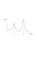
図13は、図11と同様の条件で、数式15のθ1´´(1251)および、数式1のθ´´(1252)をプロットしたグラフである。図より、角加速度低減区間1261においては、θ´´(1252)に比べてθ1´´(1251)の絶対値が小さいことが読み取れる。光走査器として使用する場合、ミラーの動たわみは、角加速度に比例するため、本発明によれば、同じミラーを使用した場合動たわみが小さくなる。また、同等の動たわみが許容できる場合には、より剛性の低いミラーを使用することができる。一般に剛性の低いミラーは、軽量に作ることができるので、慣性モーメントを低減することができ、消費電力を押さえることができる。
図1は、本実施例の光偏向器を説明するための図である。
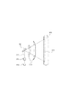
図3は、シリコンウェハをエッチング加工で作成するプレート部材200の上面図である。平板状の可動子201〜203とねじりバネ211〜213は、交互に直列接続されている。ねじりバネ211〜213の軸は直線状に配置されており、ねじりバネ213の他端は、固定枠221に連結されている。この系は3つの振動モードを有するが、それらの周波数は、およそ1:2:3の関係になるように調整が施される。これらのモードを以下モード1、モード2、モード3と称する。
図6は、本発明の光偏向器を、レーザービームプリンタ等の画像形成装置に適用した例である。光源302から出射したレーザー光311は、出射光学系303で整形され、本発明の光偏向器301で走査される。結像光学系304は、走査されたレーザー光を感光ドラム305上に結像させスポットを形成する。走査されたスポットは、走査軌跡312に沿って移動する。
101、102、201〜203、1001〜1003、1101、1102、1301、1302、1401、1402、1501、1502、1601、1602 可動子
111a、b、112a、b、211〜213、1311、1312、1511、1512、1011〜1013、1111、1112、1411、1412、1611 ねじりバネ
121、221 支持枠
1021、1121、1321、1421、1521、1522、1621 支持部
131 光反射膜
1131 光反射素子
1141 駆動手段
1151 駆動制御手段
1391、1392、1491 ねじりバネの軸に垂直な面
140 電磁アクチュエータ
141 永久磁石
142 コイル
144 ヨーク
143 コア
150 コントローラ
190 切断線
151 基準クロック生成器
152 分周器
153、154 カウンタ
155、156 正弦関数器
157、158 掛算器
159 加算器
160 DAコンバータ
161 パワーアンプ
301 本発明の光偏向器
302 光源
303 出射光学系
304 結像光学系
305 感光ドラム
311 レーザー光
312 走査軌跡
1201 数式16のθ1´
1202 数式2のθ´
1211 θ´max
1212 θ´min
1221 角速度θ1´の有効時間
1222 正弦波θ´の有効時間
1231 数式15のθ1
1232 数式1のθ
1241 本発明の最大有効変位角
1242 正弦波の最大有効変位角
1251 数式15のθ1´´
1252 数式1のθ´´
1261 角加速度低減区間
Claims (8)
- 支持部と、
第1の可動子、該第1の可動子を前記支持部に対して揺動可能に支持する第1のねじりバネ、第2の可動子、及び該第2の可動子を前記第1の可動子に対して、前記第1の可動子の揺動軸と同一の軸周りに揺動可能に支持する第2のねじりバネを少なくとも有する可動系と、
前記第1及び第2の可動子を前記揺動軸を中心に揺動させる駆動手段と、
前記駆動手段を制御する駆動制御手段と、
を有するマイクロ揺動体において、
前記可動系は、基準周波数の固有振動モードである基準振動モードと、nを1以上の整数としたときに、前記基準周波数の1.98n倍以上で2.02n倍以下の周波数の固有振動モードである偶数倍振動モードとを有し、前記駆動制御手段は、前記可動系が前記基準振動モードと前記偶数倍振動モードで同時に揺動するように前記駆動手段を制御することを特徴とするマイクロ揺動体。 - 前記第1及び第2の可動子と、前記第1及び第2のねじりバネとが一枚の板から一体に形成されている請求項1に記載のマイクロ揺動体。
- 前記一枚の板が単結晶シリコンウエハから成る請求項2に記載のマイクロ揺動体。
- 前記可動系の駆動時に、前記第1及び第2の可動子の少なくとも一方の変位角が増加している時間の長さと、前記変位角が減少している時間の長さとが異なる請求項1に記載のマイクロ揺動体。
- 前記偶数倍振動モードの周波数は、前記基準振動モードの周波数の1.98倍以上で2.02倍以下の周波数であることを特徴とする請求項1乃至請求項4のいずれか一項に記載のマイクロ揺動体。
- 前記可動系が更に、第3の可動子と、該第3の可動子を前記第2の可動子に対して、前記第1及び第2の可動子の揺動軸と同一の軸周りに揺動可能に支持する第3のねじりバネと、を有し、
前記可動系は、基準周波数の固有振動モードである基準振動モードと、前記基準周波数の2倍の周波数の固有振動モードである2倍振動モードと、前記基準周波数の3倍の周波数の固有振動モードである3倍振動モードと、を有し、
前記駆動制御手段は、前記可動系が前記基準振動モードと前記2倍振動モードと前記3倍振動モードで同時に揺動するように前記駆動手段を制御することを特徴とする請求項1に記載のマイクロ揺動体。 - 請求項1乃至5のいずれか一項に記載のマイクロ揺動体と、前記第1及び第2の可動子の少なくとも一方に設けられた光反射部とから成る光偏向器。
- レーザー光を出射する光源と、該光源から出射したレーザー光を偏向する請求項7に記載の光偏向器と、該光偏向器で偏向されたレーザー光を感光体上に結像する結像光学系とを有する画像形成装置。
Priority Applications (12)
| Application Number | Priority Date | Filing Date | Title |
|---|---|---|---|
| JP2004323758A JP4027359B2 (ja) | 2003-12-25 | 2004-11-08 | マイクロ揺動体、光偏向器、画像形成装置 |
| DE602004015328T DE602004015328D1 (de) | 2003-12-25 | 2004-12-10 | Mikroschwingendes glied, lichtablenkvorrichtung und bilderzeugungsvorrichtung |
| PCT/JP2004/018863 WO2005063613A1 (en) | 2003-12-25 | 2004-12-10 | Micro-oscillating member, light-deflector, and image-forming apparatus |
| US10/544,173 US7271943B2 (en) | 2003-12-25 | 2004-12-10 | Micro-oscillating member, light-deflector, and image-forming apparatus |
| CN2008100956575A CN101276054B (zh) | 2003-12-25 | 2004-12-10 | 微振动部件、光偏转器和成像设备 |
| EP04807221A EP1697254B1 (en) | 2003-12-25 | 2004-12-10 | Micro-oscillating member, light-deflector, and image-forming apparatus |
| CNB2004800112340A CN100429141C (zh) | 2003-12-25 | 2004-12-10 | 微振动部件、光偏转器和成像设备 |
| KR1020067012285A KR100806015B1 (ko) | 2003-12-25 | 2004-12-10 | 마이크로요동체, 광편향기 및 화상형성장치 |
| US11/780,846 US7388702B2 (en) | 2003-12-25 | 2007-07-20 | Micro-oscillating member, light-deflector, and image-forming apparatus |
| JP2007201790A JP4533407B2 (ja) | 2003-12-25 | 2007-08-02 | 画像形成装置 |
| US12/107,410 US7474452B2 (en) | 2003-12-25 | 2008-04-22 | Micro-oscillating member, light-deflector, and image-forming apparatus |
| US12/277,796 US7643198B2 (en) | 2003-12-25 | 2008-11-25 | Micro-oscillating member, light-deflector, and image-forming apparatus |
Applications Claiming Priority (2)
| Application Number | Priority Date | Filing Date | Title |
|---|---|---|---|
| JP2003430425 | 2003-12-25 | ||
| JP2004323758A JP4027359B2 (ja) | 2003-12-25 | 2004-11-08 | マイクロ揺動体、光偏向器、画像形成装置 |
Related Child Applications (1)
| Application Number | Title | Priority Date | Filing Date |
|---|---|---|---|
| JP2007201790A Division JP4533407B2 (ja) | 2003-12-25 | 2007-08-02 | 画像形成装置 |
Publications (3)
| Publication Number | Publication Date |
|---|---|
| JP2005208578A JP2005208578A (ja) | 2005-08-04 |
| JP2005208578A5 JP2005208578A5 (ja) | 2007-08-23 |
| JP4027359B2 true JP4027359B2 (ja) | 2007-12-26 |
Family
ID=34742115
Family Applications (2)
| Application Number | Title | Priority Date | Filing Date |
|---|---|---|---|
| JP2004323758A Expired - Fee Related JP4027359B2 (ja) | 2003-12-25 | 2004-11-08 | マイクロ揺動体、光偏向器、画像形成装置 |
| JP2007201790A Expired - Fee Related JP4533407B2 (ja) | 2003-12-25 | 2007-08-02 | 画像形成装置 |
Family Applications After (1)
| Application Number | Title | Priority Date | Filing Date |
|---|---|---|---|
| JP2007201790A Expired - Fee Related JP4533407B2 (ja) | 2003-12-25 | 2007-08-02 | 画像形成装置 |
Country Status (7)
| Country | Link |
|---|---|
| US (4) | US7271943B2 (ja) |
| EP (1) | EP1697254B1 (ja) |
| JP (2) | JP4027359B2 (ja) |
| KR (1) | KR100806015B1 (ja) |
| CN (2) | CN100429141C (ja) |
| DE (1) | DE602004015328D1 (ja) |
| WO (1) | WO2005063613A1 (ja) |
Cited By (2)
| Publication number | Priority date | Publication date | Assignee | Title |
|---|---|---|---|---|
| US7920313B2 (en) | 2008-03-12 | 2011-04-05 | Canon Kabushiki Kaisha | Oscillator device, optical deflector and image forming apparatus using the optical deflector |
| US7924490B2 (en) | 2008-03-12 | 2011-04-12 | Canon Kabushiki Kaisha | Oscillator device, optical deflector and image forming apparatus using the optical deflector |
Families Citing this family (68)
| Publication number | Priority date | Publication date | Assignee | Title |
|---|---|---|---|---|
| US7446911B2 (en) * | 2002-11-26 | 2008-11-04 | Brother Kogyo Kabushiki Kaisha | Optical scanning apparatus and image forming apparatus |
| JP4385938B2 (ja) * | 2004-12-15 | 2009-12-16 | セイコーエプソン株式会社 | アクチュエータ |
| US7573625B2 (en) * | 2005-07-07 | 2009-08-11 | Lexmark International, Inc. | Multiharmonic galvanometric scanning device |
| JP5164345B2 (ja) * | 2005-08-22 | 2013-03-21 | キヤノン株式会社 | 光走査装置及びそれを用いた画像形成装置 |
| KR20080044239A (ko) * | 2005-08-26 | 2008-05-20 | 가부시키가이샤 니콘 | 유지 장치, 조립 시스템, 스퍼터링 장치, 그리고 가공 방법및 가공 장치 |
| US7474165B2 (en) | 2005-11-22 | 2009-01-06 | Canon Kabushiki Kaisha | Oscillating device, optical deflector and optical instrument using the same |
| US7436566B2 (en) * | 2005-11-22 | 2008-10-14 | Canon Kabushiki Kaisha | Oscillating device, optical deflector and method of controlling the same |
| US7817318B2 (en) * | 2005-12-09 | 2010-10-19 | Canon Kabushiki Kaisha | Oscillating system and optical deflector |
| JP5441309B2 (ja) * | 2006-02-13 | 2014-03-12 | キヤノン株式会社 | 揺動体装置、及び光偏向装置 |
| JP2007219083A (ja) | 2006-02-15 | 2007-08-30 | Canon Inc | 光走査装置及びそれを用いた画像形成装置 |
| KR100694599B1 (ko) * | 2006-03-29 | 2007-03-14 | 삼성전자주식회사 | 메카닉 필터를 구비한 엑츄에이터 |
| JP2007316443A (ja) * | 2006-05-26 | 2007-12-06 | Canon Inc | 光偏向器、及びそれを用いた光学機器 |
| JP4881073B2 (ja) * | 2006-05-30 | 2012-02-22 | キヤノン株式会社 | 光偏向器、及びそれを用いた光学機器 |
| JP5170983B2 (ja) | 2006-05-30 | 2013-03-27 | キヤノン株式会社 | 光偏向器、及びそれを用いた光学機器 |
| JP2007322466A (ja) * | 2006-05-30 | 2007-12-13 | Canon Inc | 光偏向器、及びそれを用いた光学機器 |
| WO2008105888A2 (en) * | 2006-05-31 | 2008-09-04 | Georgia Tech Research Corporation | Integrated sensing probes, methods of fabrication thereof, and methods of use thereof |
| JP5121301B2 (ja) * | 2006-06-07 | 2013-01-16 | キヤノン株式会社 | 揺動体装置、光偏向器、及びそれを用いた光学機器 |
| JP2008083688A (ja) * | 2006-08-28 | 2008-04-10 | Canon Inc | 光走査装置及びそれを用いた画像形成装置 |
| JP2008058752A (ja) | 2006-09-01 | 2008-03-13 | Canon Inc | 光偏向装置、及びこれを用いた画像形成装置 |
| JP2008134601A (ja) * | 2006-11-01 | 2008-06-12 | Canon Inc | 画像形成装置 |
| JP5103876B2 (ja) * | 2006-11-16 | 2012-12-19 | 株式会社デンソー | 2次元光走査装置 |
| CN105581776B (zh) * | 2007-01-10 | 2018-10-16 | 光学实验室成像公司 | 用于可调谐滤波器线性化的装置和方法以及线性化可调谐滤波器 |
| JP5184905B2 (ja) * | 2007-03-23 | 2013-04-17 | キヤノン株式会社 | 揺動体装置、光偏向器、光偏向器を用いた画像形成装置 |
| JP5064864B2 (ja) | 2007-04-02 | 2012-10-31 | キヤノン株式会社 | 光偏向装置、画像形成装置、及び光偏向装置の駆動方法 |
| JP5058661B2 (ja) * | 2007-04-17 | 2012-10-24 | キヤノン株式会社 | 画像形成装置 |
| JP5072658B2 (ja) | 2007-05-17 | 2012-11-14 | キヤノン株式会社 | 揺動体装置、光偏向装置、及び駆動信号生成方法 |
| JP2008286974A (ja) * | 2007-05-17 | 2008-11-27 | Canon Inc | 揺動体装置、光偏向装置、及び駆動信号生成方法 |
| JP5014235B2 (ja) | 2007-05-17 | 2012-08-29 | キヤノン株式会社 | 揺動体装置、光偏向器、光偏向器を用いた画像形成装置 |
| JP2008299297A (ja) * | 2007-06-04 | 2008-12-11 | Canon Inc | 揺動体装置、及び揺動体装置の振動系の駆動制御方法 |
| JP5065116B2 (ja) * | 2007-06-14 | 2012-10-31 | キヤノン株式会社 | 揺動体装置、光偏向装置、及びその制御方法 |
| JP2009006522A (ja) | 2007-06-26 | 2009-01-15 | Canon Inc | 画像形成装置及びその制御方法、コンピュータプログラム |
| JP2009018457A (ja) | 2007-07-10 | 2009-01-29 | Canon Inc | 画像形成装置及びその制御方法、コンピュータプログラム |
| JP2009042737A (ja) * | 2007-07-13 | 2009-02-26 | Canon Inc | 揺動体装置、及びそれを用いた光偏向器 |
| JP5432441B2 (ja) * | 2007-07-13 | 2014-03-05 | キヤノン株式会社 | 揺動体装置、及びそれを用いた光偏向器 |
| JP2009025617A (ja) * | 2007-07-20 | 2009-02-05 | Canon Inc | 揺動体装置、光偏向器およびそれを用いた光学機器 |
| JP2009034961A (ja) * | 2007-08-03 | 2009-02-19 | Canon Inc | 画像形成装置 |
| JP2009058616A (ja) * | 2007-08-30 | 2009-03-19 | Canon Inc | 揺動体装置、光偏向装置、及びそれを用いた画像形成装置 |
| JP4974839B2 (ja) * | 2007-10-17 | 2012-07-11 | キヤノン株式会社 | 光偏向装置及び画像形成装置 |
| KR20090041766A (ko) * | 2007-10-24 | 2009-04-29 | 삼성전기주식회사 | 미러로부터 분리된 액츄에이터를 구비한 멤스 스캐너 |
| JP2009122383A (ja) | 2007-11-14 | 2009-06-04 | Canon Inc | 揺動体装置の製造方法、該製造方法により製造された揺動体装置によって構成される光偏向器及び光学機器 |
| JP5554895B2 (ja) * | 2008-02-20 | 2014-07-23 | キヤノン株式会社 | 揺動構造体、及び揺動構造体を用いた揺動体装置 |
| JP5283966B2 (ja) | 2008-05-14 | 2013-09-04 | キヤノン株式会社 | 光偏向装置、及び画像形成装置 |
| JP5296428B2 (ja) * | 2008-06-20 | 2013-09-25 | キヤノン電子株式会社 | 光走査装置及び該光走査装置を用いた画像形成装置、及び画像読み取り装置とディスプレイ |
| JP2010014871A (ja) * | 2008-07-02 | 2010-01-21 | Canon Inc | 揺動体装置、光偏向装置、光学機器、及び共振周波数検出方法 |
| JP2010019871A (ja) * | 2008-07-08 | 2010-01-28 | Canon Inc | 揺動体装置、揺動体装置を用いた光学機器 |
| JP2010048928A (ja) * | 2008-08-20 | 2010-03-04 | Canon Inc | 揺動体装置、及びそれを用いた光偏向装置 |
| DE102008042967B4 (de) | 2008-10-20 | 2017-04-06 | Robert Bosch Gmbh | Kaskadierte mikromechanische Aktuatorstruktur |
| KR20100054711A (ko) | 2008-11-14 | 2010-05-25 | 메디포스트(주) | 간엽 줄기세포 또는 이의 배양액을 포함하는 신경질환의 예방 또는 치료용 조성물 |
| JP5404342B2 (ja) | 2009-01-06 | 2014-01-29 | キヤノン株式会社 | 光学走査装置及びそれを用いた画像形成装置 |
| WO2010144166A1 (en) * | 2009-06-12 | 2010-12-16 | University Of Florida Research Foundation Inc. | Electromechanical inductors and transformers |
| JP5287748B2 (ja) * | 2010-01-29 | 2013-09-11 | 三菱電機株式会社 | 光路制御装置および投射型画像表示装置 |
| TWI416168B (zh) * | 2010-02-05 | 2013-11-21 | Ind Tech Res Inst | 光學多環掃描元件 |
| JP5470346B2 (ja) * | 2011-08-23 | 2014-04-16 | 京セラドキュメントソリューションズ株式会社 | 光走査装置及びこれを用いた画像形成装置 |
| US9520813B2 (en) * | 2011-10-27 | 2016-12-13 | Panasonic Intellectual Property Management Co., Ltd. | Actuator drive device |
| US10730742B2 (en) * | 2012-01-24 | 2020-08-04 | Pioneer Corporation | Actuator with plurality of torsion bars having varying spring constant |
| WO2014192123A1 (ja) * | 2013-05-30 | 2014-12-04 | パイオニア株式会社 | 剛体構造体 |
| JP2015022206A (ja) | 2013-07-22 | 2015-02-02 | 船井電機株式会社 | 振動ミラー素子および距離計測装置 |
| JP5714196B1 (ja) * | 2014-04-23 | 2015-05-07 | 三菱電機株式会社 | ガルバノスキャナおよびレーザ加工装置 |
| DE102015216811B4 (de) * | 2015-09-02 | 2023-06-29 | Robert Bosch Gmbh | Schwenkvorrichtung für einen Mikrospiegel |
| JP6643697B2 (ja) * | 2015-09-24 | 2020-02-12 | ミツミ電機株式会社 | 電磁変換装置及びアクチュエータ及びポンプ |
| JP6585147B2 (ja) * | 2017-12-01 | 2019-10-02 | 浜松ホトニクス株式会社 | アクチュエータ装置 |
| US11394284B2 (en) * | 2017-12-01 | 2022-07-19 | Hamamatsu Photonics K.K. | Actuator device |
| EP3521894B1 (en) * | 2018-02-06 | 2023-11-08 | Murata Manufacturing Co., Ltd. | Mems reflector system with trajectory control |
| KR102845738B1 (ko) * | 2018-08-10 | 2025-08-13 | 하마마츠 포토닉스 가부시키가이샤 | 액추에이터 장치, 및 액추에이터 장치의 제조 방법 |
| CN110095858B (zh) * | 2018-12-12 | 2021-06-08 | 中国科学院紫金山天文台 | 自适应光学变形镜弹性模态像差表征方法 |
| JP7297607B2 (ja) * | 2019-09-04 | 2023-06-26 | キヤノン株式会社 | 画像処理装置及びその制御方法、並びにプログラム |
| JP7309543B2 (ja) * | 2019-09-12 | 2023-07-18 | キヤノン株式会社 | 画像処理装置及びその制御方法、並びにプログラム |
| JP7587994B2 (ja) * | 2021-01-28 | 2024-11-21 | 浜松ホトニクス株式会社 | アクチュエータデバイスの製造方法 |
Family Cites Families (28)
| Publication number | Priority date | Publication date | Assignee | Title |
|---|---|---|---|---|
| US4317611A (en) * | 1980-05-19 | 1982-03-02 | International Business Machines Corporation | Optical ray deflection apparatus |
| JPS6449015A (en) * | 1987-08-20 | 1989-02-23 | Seiko Epson Corp | Two-dimensional optical drawing device |
| US4859846A (en) * | 1988-07-21 | 1989-08-22 | Burrer Gordon J | Dual-mode resonant scanning system |
| US5025346A (en) * | 1989-02-17 | 1991-06-18 | Regents Of The University Of California | Laterally driven resonant microstructures |
| US5257041A (en) * | 1991-06-28 | 1993-10-26 | Eastman Kodak Company | Method and circuit for driving an electromechanical device rapidly with great precision |
| JP3003429B2 (ja) * | 1992-10-08 | 2000-01-31 | 富士電機株式会社 | ねじり振動子および光偏向子 |
| JP3214583B2 (ja) * | 1993-07-07 | 2001-10-02 | 富士電機株式会社 | 光偏向子 |
| JP3787877B2 (ja) | 1996-02-20 | 2006-06-21 | ブラザー工業株式会社 | 光走査装置 |
| JP3584595B2 (ja) | 1996-02-20 | 2004-11-04 | ブラザー工業株式会社 | 光走査装置 |
| JP3543473B2 (ja) | 1996-02-20 | 2004-07-14 | ブラザー工業株式会社 | 光走査装置 |
| JP3785668B2 (ja) | 1996-02-26 | 2006-06-14 | ブラザー工業株式会社 | 光走査装置 |
| US5992233A (en) * | 1996-05-31 | 1999-11-30 | The Regents Of The University Of California | Micromachined Z-axis vibratory rate gyroscope |
| JPH10293134A (ja) * | 1997-02-19 | 1998-11-04 | Canon Inc | 光検出または照射用のプローブ、及び該プローブを備えた近視野光学顕微鏡・記録再生装置・露光装置、並びに該プローブの製造方法 |
| DE69738717D1 (de) * | 1997-03-25 | 2008-07-03 | Sunstar Inc | Verfahren zur rekalzifizierung der zähne |
| JPH11166935A (ja) * | 1997-09-25 | 1999-06-22 | Canon Inc | 光検出または照射用の光プローブと該プローブを備えた近視野光学顕微鏡、及該光プローブの製造方法とその製造に用いる基板 |
| US6477132B1 (en) * | 1998-08-19 | 2002-11-05 | Canon Kabushiki Kaisha | Probe and information recording/reproduction apparatus using the same |
| JP3554233B2 (ja) * | 1998-10-28 | 2004-08-18 | キヤノン株式会社 | 光プローブの製造方法 |
| JP2000147395A (ja) * | 1998-11-16 | 2000-05-26 | Nikon Corp | サンプリングクロック発生装置 |
| US6497141B1 (en) * | 1999-06-07 | 2002-12-24 | Cornell Research Foundation Inc. | Parametric resonance in microelectromechanical structures |
| JP3513448B2 (ja) * | 1999-11-11 | 2004-03-31 | キヤノン株式会社 | 光プローブ |
| JP2001264676A (ja) * | 2000-03-14 | 2001-09-26 | Olympus Optical Co Ltd | 光スキャナ |
| US6396616B1 (en) * | 2000-10-10 | 2002-05-28 | 3M Innovative Properties Company | Direct laser imaging system |
| US7038832B2 (en) | 2000-10-27 | 2006-05-02 | Seiko Epson Corporation | Electrophoretic display, method for making the electrophoretic display, and electronic apparatus |
| JP2002277811A (ja) * | 2001-03-22 | 2002-09-25 | Olympus Optical Co Ltd | 光スキャナ駆動装置および方法 |
| US6710680B2 (en) * | 2001-12-20 | 2004-03-23 | Motorola, Inc. | Reduced size, low loss MEMS torsional hinges and MEMS resonators employing such hinges |
| JP4174226B2 (ja) | 2002-03-25 | 2008-10-29 | キヤノン株式会社 | 光走査光学系及びそれを用いた画像形成装置 |
| JP3862623B2 (ja) * | 2002-07-05 | 2006-12-27 | キヤノン株式会社 | 光偏向器及びその製造方法 |
| JP2005173411A (ja) * | 2003-12-12 | 2005-06-30 | Canon Inc | 光偏向器 |
-
2004
- 2004-11-08 JP JP2004323758A patent/JP4027359B2/ja not_active Expired - Fee Related
- 2004-12-10 US US10/544,173 patent/US7271943B2/en not_active Expired - Fee Related
- 2004-12-10 WO PCT/JP2004/018863 patent/WO2005063613A1/en not_active Ceased
- 2004-12-10 CN CNB2004800112340A patent/CN100429141C/zh not_active Expired - Fee Related
- 2004-12-10 DE DE602004015328T patent/DE602004015328D1/de not_active Expired - Lifetime
- 2004-12-10 EP EP04807221A patent/EP1697254B1/en not_active Expired - Lifetime
- 2004-12-10 KR KR1020067012285A patent/KR100806015B1/ko not_active Expired - Fee Related
- 2004-12-10 CN CN2008100956575A patent/CN101276054B/zh not_active Expired - Fee Related
-
2007
- 2007-07-20 US US11/780,846 patent/US7388702B2/en not_active Expired - Fee Related
- 2007-08-02 JP JP2007201790A patent/JP4533407B2/ja not_active Expired - Fee Related
-
2008
- 2008-04-22 US US12/107,410 patent/US7474452B2/en not_active Expired - Fee Related
- 2008-11-25 US US12/277,796 patent/US7643198B2/en not_active Expired - Fee Related
Cited By (2)
| Publication number | Priority date | Publication date | Assignee | Title |
|---|---|---|---|---|
| US7920313B2 (en) | 2008-03-12 | 2011-04-05 | Canon Kabushiki Kaisha | Oscillator device, optical deflector and image forming apparatus using the optical deflector |
| US7924490B2 (en) | 2008-03-12 | 2011-04-12 | Canon Kabushiki Kaisha | Oscillator device, optical deflector and image forming apparatus using the optical deflector |
Also Published As
| Publication number | Publication date |
|---|---|
| US7643198B2 (en) | 2010-01-05 |
| US20090080044A1 (en) | 2009-03-26 |
| KR100806015B1 (ko) | 2008-02-26 |
| JP2005208578A (ja) | 2005-08-04 |
| US20080204843A1 (en) | 2008-08-28 |
| KR20060103927A (ko) | 2006-10-04 |
| US20060152785A1 (en) | 2006-07-13 |
| JP2008009446A (ja) | 2008-01-17 |
| US20080013140A1 (en) | 2008-01-17 |
| CN1780786A (zh) | 2006-05-31 |
| EP1697254B1 (en) | 2008-07-23 |
| CN101276054B (zh) | 2010-12-08 |
| US7388702B2 (en) | 2008-06-17 |
| CN100429141C (zh) | 2008-10-29 |
| DE602004015328D1 (de) | 2008-09-04 |
| EP1697254A4 (en) | 2007-03-28 |
| CN101276054A (zh) | 2008-10-01 |
| US7474452B2 (en) | 2009-01-06 |
| WO2005063613A1 (en) | 2005-07-14 |
| US7271943B2 (en) | 2007-09-18 |
| JP4533407B2 (ja) | 2010-09-01 |
| EP1697254A1 (en) | 2006-09-06 |
Similar Documents
| Publication | Publication Date | Title |
|---|---|---|
| JP4027359B2 (ja) | マイクロ揺動体、光偏向器、画像形成装置 | |
| JP4574396B2 (ja) | 光偏向器 | |
| JP4881073B2 (ja) | 光偏向器、及びそれを用いた光学機器 | |
| JP5065116B2 (ja) | 揺動体装置、光偏向装置、及びその制御方法 | |
| JP5170983B2 (ja) | 光偏向器、及びそれを用いた光学機器 | |
| JP2009058616A (ja) | 揺動体装置、光偏向装置、及びそれを用いた画像形成装置 | |
| JP2008299297A (ja) | 揺動体装置、及び揺動体装置の振動系の駆動制御方法 | |
| JP5554895B2 (ja) | 揺動構造体、及び揺動構造体を用いた揺動体装置 | |
| JP4447963B2 (ja) | 光偏向器制御装置 | |
| JP5341372B2 (ja) | 揺動体装置、揺動体装置を用いた画像形成装置 | |
| JP2008058752A (ja) | 光偏向装置、及びこれを用いた画像形成装置 | |
| JP5084385B2 (ja) | ねじりバネ、光偏向器及びそれを用いた画像形成装置 | |
| JP2006313216A (ja) | 揺動体装置、およびそれを用いた光偏向器 | |
| JP5408887B2 (ja) | 揺動体装置、揺動体装置を用いた画像形成装置 | |
| JP2008070398A (ja) | 揺動装置、揺動装置を用いた光偏向装置、揺動装置の周波数調整方法及び装置、並びに光偏向装置を用いた画像形成装置 | |
| JP2009042579A (ja) | 光偏向装置、及び揺動体のジッタ抑制方法 | |
| JP2009276637A (ja) | 揺動体装置、光偏向装置、及びそれを用いた光学機器 |
Legal Events
| Date | Code | Title | Description |
|---|---|---|---|
| A521 | Request for written amendment filed |
Free format text: JAPANESE INTERMEDIATE CODE: A523 Effective date: 20051128 |
|
| A621 | Written request for application examination |
Free format text: JAPANESE INTERMEDIATE CODE: A621 Effective date: 20051128 |
|
| A521 | Request for written amendment filed |
Free format text: JAPANESE INTERMEDIATE CODE: A523 Effective date: 20070710 |
|
| A871 | Explanation of circumstances concerning accelerated examination |
Free format text: JAPANESE INTERMEDIATE CODE: A871 Effective date: 20070710 |
|
| A975 | Report on accelerated examination |
Free format text: JAPANESE INTERMEDIATE CODE: A971005 Effective date: 20070731 |
|
| A131 | Notification of reasons for refusal |
Free format text: JAPANESE INTERMEDIATE CODE: A131 Effective date: 20070807 |
|
| A521 | Request for written amendment filed |
Free format text: JAPANESE INTERMEDIATE CODE: A523 Effective date: 20070829 |
|
| TRDD | Decision of grant or rejection written | ||
| A01 | Written decision to grant a patent or to grant a registration (utility model) |
Free format text: JAPANESE INTERMEDIATE CODE: A01 Effective date: 20070925 |
|
| A61 | First payment of annual fees (during grant procedure) |
Free format text: JAPANESE INTERMEDIATE CODE: A61 Effective date: 20071009 |
|
| FPAY | Renewal fee payment (event date is renewal date of database) |
Free format text: PAYMENT UNTIL: 20101019 Year of fee payment: 3 |
|
| R150 | Certificate of patent or registration of utility model |
Ref document number: 4027359 Country of ref document: JP Free format text: JAPANESE INTERMEDIATE CODE: R150 Free format text: JAPANESE INTERMEDIATE CODE: R150 |
|
| FPAY | Renewal fee payment (event date is renewal date of database) |
Free format text: PAYMENT UNTIL: 20101019 Year of fee payment: 3 |
|
| FPAY | Renewal fee payment (event date is renewal date of database) |
Free format text: PAYMENT UNTIL: 20111019 Year of fee payment: 4 |
|
| FPAY | Renewal fee payment (event date is renewal date of database) |
Free format text: PAYMENT UNTIL: 20111019 Year of fee payment: 4 |
|
| FPAY | Renewal fee payment (event date is renewal date of database) |
Free format text: PAYMENT UNTIL: 20121019 Year of fee payment: 5 |
|
| FPAY | Renewal fee payment (event date is renewal date of database) |
Free format text: PAYMENT UNTIL: 20131019 Year of fee payment: 6 |
|
| LAPS | Cancellation because of no payment of annual fees |