JP2012148762A - 車両のハーネス配設構造 - Google Patents
車両のハーネス配設構造 Download PDFInfo
- Publication number
- JP2012148762A JP2012148762A JP2011249542A JP2011249542A JP2012148762A JP 2012148762 A JP2012148762 A JP 2012148762A JP 2011249542 A JP2011249542 A JP 2011249542A JP 2011249542 A JP2011249542 A JP 2011249542A JP 2012148762 A JP2012148762 A JP 2012148762A
- Authority
- JP
- Japan
- Prior art keywords
- harness
- vehicle
- arrangement structure
- storage device
- control device
- Prior art date
- Legal status (The legal status is an assumption and is not a legal conclusion. Google has not performed a legal analysis and makes no representation as to the accuracy of the status listed.)
- Granted
Links
Images


Classifications
-
- B—PERFORMING OPERATIONS; TRANSPORTING
- B60—VEHICLES IN GENERAL
- B60R—VEHICLES, VEHICLE FITTINGS, OR VEHICLE PARTS, NOT OTHERWISE PROVIDED FOR
- B60R16/00—Electric or fluid circuits specially adapted for vehicles and not otherwise provided for; Arrangement of elements of electric or fluid circuits specially adapted for vehicles and not otherwise provided for
- B60R16/02—Electric or fluid circuits specially adapted for vehicles and not otherwise provided for; Arrangement of elements of electric or fluid circuits specially adapted for vehicles and not otherwise provided for electric constitutive elements
- B60R16/0207—Wire harnesses
- B60R16/0215—Protecting, fastening and routing means therefor
-
- H—ELECTRICITY
- H01—ELECTRIC ELEMENTS
- H01M—PROCESSES OR MEANS, e.g. BATTERIES, FOR THE DIRECT CONVERSION OF CHEMICAL ENERGY INTO ELECTRICAL ENERGY
- H01M10/00—Secondary cells; Manufacture thereof
- H01M10/42—Methods or arrangements for servicing or maintenance of secondary cells or secondary half-cells
- H01M10/425—Structural combination with electronic components, e.g. electronic circuits integrated to the outside of the casing
-
- H—ELECTRICITY
- H01—ELECTRIC ELEMENTS
- H01M—PROCESSES OR MEANS, e.g. BATTERIES, FOR THE DIRECT CONVERSION OF CHEMICAL ENERGY INTO ELECTRICAL ENERGY
- H01M10/00—Secondary cells; Manufacture thereof
- H01M10/60—Heating or cooling; Temperature control
- H01M10/61—Types of temperature control
- H01M10/613—Cooling or keeping cold
-
- H—ELECTRICITY
- H01—ELECTRIC ELEMENTS
- H01M—PROCESSES OR MEANS, e.g. BATTERIES, FOR THE DIRECT CONVERSION OF CHEMICAL ENERGY INTO ELECTRICAL ENERGY
- H01M10/00—Secondary cells; Manufacture thereof
- H01M10/60—Heating or cooling; Temperature control
- H01M10/62—Heating or cooling; Temperature control specially adapted for specific applications
- H01M10/625—Vehicles
-
- H—ELECTRICITY
- H01—ELECTRIC ELEMENTS
- H01M—PROCESSES OR MEANS, e.g. BATTERIES, FOR THE DIRECT CONVERSION OF CHEMICAL ENERGY INTO ELECTRICAL ENERGY
- H01M2220/00—Batteries for particular applications
- H01M2220/20—Batteries in motive systems, e.g. vehicle, ship, plane
-
- Y—GENERAL TAGGING OF NEW TECHNOLOGICAL DEVELOPMENTS; GENERAL TAGGING OF CROSS-SECTIONAL TECHNOLOGIES SPANNING OVER SEVERAL SECTIONS OF THE IPC; TECHNICAL SUBJECTS COVERED BY FORMER USPC CROSS-REFERENCE ART COLLECTIONS [XRACs] AND DIGESTS
- Y02—TECHNOLOGIES OR APPLICATIONS FOR MITIGATION OR ADAPTATION AGAINST CLIMATE CHANGE
- Y02E—REDUCTION OF GREENHOUSE GAS [GHG] EMISSIONS, RELATED TO ENERGY GENERATION, TRANSMISSION OR DISTRIBUTION
- Y02E60/00—Enabling technologies; Technologies with a potential or indirect contribution to GHG emissions mitigation
- Y02E60/10—Energy storage using batteries
Landscapes
- Engineering & Computer Science (AREA)
- Microelectronics & Electronic Packaging (AREA)
- Manufacturing & Machinery (AREA)
- Chemical & Material Sciences (AREA)
- Chemical Kinetics & Catalysis (AREA)
- Electrochemistry (AREA)
- General Chemical & Material Sciences (AREA)
- Mechanical Engineering (AREA)
- Body Structure For Vehicles (AREA)
Abstract
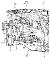
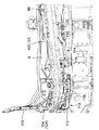
【解決手段】車両前後方向に延びる左右一対のフロントサイドフレーム5と、該両フロントサイドフレーム5間に配設された内燃機関と、上記フロントサイドフレーム5の外方側に配設されたフロントタイヤ3とを備えた車両のハーネス配設構造であって、上記フロントサイドフレーム5よりも車幅方向外方側で、かつ上記フロントタイヤ3の前方側に配設された蓄電装置70と、該蓄電装置70と車幅方向の同じ側で、かつ上記フロントタイヤ3の後方側に配設された蓄電装置用の電力制御装置と、該電力制御装置と上記蓄電装置70とを繋ぐハーネス94とを備えた。
【選択図】図11
Description
2 エンジンルーム
3 フロントタイヤ
4 車室
5 フロントサイドフレーム
6 クラッシュカン
8 フロアパネル
9 ダッシュパネル
16 ホイールエプロンメンバ
31 サスペンションクロスメンバ
32 クロスメンバ
70 蓄電装置
85 電力供給装置
86 第1ハーネス
92 電力制御装置
93 マッドガード
94 第2ハーネス
99 挿通孔
110 第2プロテクタ部材
113 第3プロテクタ部材
114 第4プロテクタ部材
116 フロアフレーム(フレーム部材)
Claims (7)
- 車両前後方向に延びる左右一対のフロントサイドフレームと、該両フロントサイドフレーム間に配設された内燃機関と、上記フロントサイドフレームの外方側に配設されたフロントタイヤとを備えた車両のハーネス配設構造であって、上記フロントサイドフレームよりも車幅方向外方側で、かつ上記フロントタイヤの前方側に配設された蓄電装置と、該蓄電装置と車幅方向の同じ側で、かつ上記フロントタイヤの後方側に配設された蓄電装置用の電力制御装置と、該電力制御装置と上記蓄電装置とを繋ぐハーネスとを備えたことを特徴とする車両のハーネス配設構造。
- 請求項1記載の車両のハーネス配設構造において、上記ハーネスは、フロントタイヤの上部に形成されたホイールアーチに沿って配策されたことを特徴とする車両のハーネス配設構造。
- 請求項2記載の車両のハーネス配設構造において、上記ハーネスは、ホイールアーチを形成するマッドガードと、その上方に設置されたホイールエプロンメンバとの間に配策されたことを特徴とする車両のハーネス配設構造。
- 請求項1〜3のいずれか1項に記載の車両のハーネス配設構造において、上記ハーネスが車室の前部に位置するダッシュパネルの側辺部前面に沿って配策されるとともに、該ハーネスを保護するプロテクタ部材がダッシュパネルの側辺部前面に沿って設置されたことを特徴とする車両のハーネス配設構造。
- 請求項1〜4のいずれか1項に記載の車両のハーネス配設構造において、上記電力制御装置が車室の底面に位置するフロアパネルの上方に配設され、上記ハーネスが上記電力制御装置の設置部近傍までフロアパネルの下面に沿って配策されるとともに、該フロアパネルの上方に導出されて上記電力制御装置に接続されたことを特徴とする車両のハーネス配設構造。
- 請求項5に記載の車両のハーネス配設構造において、上記フロアパネルの下面に沿って配策された上記ハーネスを保護するプロテクタ部材を有し、該プロテクタ部材が、上記フロアパネルの下面に沿って設置されたフレーム部材の下端面よりも上方に配設されたことを特徴とする車両のハーネス配設構造。
- 請求項1〜6のいずれか1項に車両のハーネス配設構造において、上記左右一対のフロントサイドフレームを連結するように車幅方向に延びるクロスメンバを有するとともに、上記両フロントサイドフレームの間に電力供給装置が配置され、かつ該電力供給装置と上記蓄電装置とを繋ぐハーネスが上記クロスメンバに沿って設置されたことを特徴とする車両のハーネス配設構造。
Priority Applications (4)
| Application Number | Priority Date | Filing Date | Title |
|---|---|---|---|
| JP2011249542A JP5857655B2 (ja) | 2010-12-27 | 2011-11-15 | 車両のハーネス配設構造 |
| DE102011121517.8A DE102011121517B4 (de) | 2010-12-27 | 2011-12-16 | Kabelbaumanordnungsstruktur eines Fahrzeugs sowie Verfahren zum Anordnen eines Kabelbaums |
| US13/331,916 US8365858B2 (en) | 2010-12-27 | 2011-12-20 | Harness arrangement structure of vehicle |
| CN201110440235.9A CN102555754B (zh) | 2010-12-27 | 2011-12-23 | 车辆的线束设置结构 |
Applications Claiming Priority (3)
| Application Number | Priority Date | Filing Date | Title |
|---|---|---|---|
| JP2010291194 | 2010-12-27 | ||
| JP2010291194 | 2010-12-27 | ||
| JP2011249542A JP5857655B2 (ja) | 2010-12-27 | 2011-11-15 | 車両のハーネス配設構造 |
Publications (2)
| Publication Number | Publication Date |
|---|---|
| JP2012148762A true JP2012148762A (ja) | 2012-08-09 |
| JP5857655B2 JP5857655B2 (ja) | 2016-02-10 |
Family
ID=46791461
Family Applications (1)
| Application Number | Title | Priority Date | Filing Date |
|---|---|---|---|
| JP2011249542A Expired - Fee Related JP5857655B2 (ja) | 2010-12-27 | 2011-11-15 | 車両のハーネス配設構造 |
Country Status (2)
| Country | Link |
|---|---|
| JP (1) | JP5857655B2 (ja) |
| DE (1) | DE102011121517B4 (ja) |
Cited By (2)
| Publication number | Priority date | Publication date | Assignee | Title |
|---|---|---|---|---|
| JP2014028596A (ja) * | 2012-07-31 | 2014-02-13 | Mazda Motor Corp | 蓄電装置の放電装置 |
| JP2015054621A (ja) * | 2013-09-12 | 2015-03-23 | 株式会社オートネットワーク技術研究所 | 車両用電源装置 |
Citations (8)
| Publication number | Priority date | Publication date | Assignee | Title |
|---|---|---|---|---|
| JPH04125958U (ja) * | 1991-05-08 | 1992-11-17 | 日産自動車株式会社 | フエンダープロテクターの取付構造 |
| JPH06239147A (ja) * | 1993-02-12 | 1994-08-30 | Mazda Motor Corp | 自動車の前部構造 |
| JP2000092616A (ja) * | 1998-09-09 | 2000-03-31 | Honda Motor Co Ltd | 電気自動車におけるカプラーの保護構造 |
| JP2000247261A (ja) * | 1999-02-26 | 2000-09-12 | Nissan Motor Co Ltd | 車体フロア構造 |
| JP2001334889A (ja) * | 2000-05-30 | 2001-12-04 | Nissan Motor Co Ltd | 車両用長尺配索部材の配索方法、配索構造 |
| JP2008211945A (ja) * | 2007-02-28 | 2008-09-11 | Hitachi Ltd | 車両駆動装置 |
| JP2009124924A (ja) * | 2007-11-19 | 2009-06-04 | Nissan Motor Co Ltd | ハーネスプロテクタ |
| JP2010051042A (ja) * | 2008-08-19 | 2010-03-04 | Yazaki Corp | プロテクタ及びワイヤハーネス |
Family Cites Families (8)
| Publication number | Priority date | Publication date | Assignee | Title |
|---|---|---|---|---|
| DE4231049C2 (de) | 1992-09-17 | 1996-01-11 | Daimler Benz Ag | Kabel- und Leitungskanal |
| JP3923281B2 (ja) | 2001-06-13 | 2007-05-30 | 本田技研工業株式会社 | 車両用機器の取付構造 |
| US6491120B1 (en) | 2002-01-18 | 2002-12-10 | Ford Global Technologies, Inc. | Method for operating a hybrid vehicle and a hybrid vehicle incorporating the method |
| US7185725B2 (en) | 2003-07-07 | 2007-03-06 | Mazda Motor Corporation | Layout structure of driving device for vehicle |
| JP2006281806A (ja) | 2005-03-31 | 2006-10-19 | Mazda Motor Corp | 車両用エンジン補機の配設構造 |
| JP2006089040A (ja) | 2005-11-21 | 2006-04-06 | Toyota Motor Corp | 燃料電池搭載車両 |
| JP5057037B2 (ja) | 2007-03-05 | 2012-10-24 | マツダ株式会社 | 自動車用バッテリ配設構造 |
| DE112012003219B4 (de) | 2011-08-01 | 2018-02-08 | Mazda Motor Corp. | Geräuschdämmungsstruktur für ein Fahrzeug |
-
2011
- 2011-11-15 JP JP2011249542A patent/JP5857655B2/ja not_active Expired - Fee Related
- 2011-12-16 DE DE102011121517.8A patent/DE102011121517B4/de not_active Expired - Fee Related
Patent Citations (8)
| Publication number | Priority date | Publication date | Assignee | Title |
|---|---|---|---|---|
| JPH04125958U (ja) * | 1991-05-08 | 1992-11-17 | 日産自動車株式会社 | フエンダープロテクターの取付構造 |
| JPH06239147A (ja) * | 1993-02-12 | 1994-08-30 | Mazda Motor Corp | 自動車の前部構造 |
| JP2000092616A (ja) * | 1998-09-09 | 2000-03-31 | Honda Motor Co Ltd | 電気自動車におけるカプラーの保護構造 |
| JP2000247261A (ja) * | 1999-02-26 | 2000-09-12 | Nissan Motor Co Ltd | 車体フロア構造 |
| JP2001334889A (ja) * | 2000-05-30 | 2001-12-04 | Nissan Motor Co Ltd | 車両用長尺配索部材の配索方法、配索構造 |
| JP2008211945A (ja) * | 2007-02-28 | 2008-09-11 | Hitachi Ltd | 車両駆動装置 |
| JP2009124924A (ja) * | 2007-11-19 | 2009-06-04 | Nissan Motor Co Ltd | ハーネスプロテクタ |
| JP2010051042A (ja) * | 2008-08-19 | 2010-03-04 | Yazaki Corp | プロテクタ及びワイヤハーネス |
Cited By (2)
| Publication number | Priority date | Publication date | Assignee | Title |
|---|---|---|---|---|
| JP2014028596A (ja) * | 2012-07-31 | 2014-02-13 | Mazda Motor Corp | 蓄電装置の放電装置 |
| JP2015054621A (ja) * | 2013-09-12 | 2015-03-23 | 株式会社オートネットワーク技術研究所 | 車両用電源装置 |
Also Published As
| Publication number | Publication date |
|---|---|
| JP5857655B2 (ja) | 2016-02-10 |
| DE102011121517B4 (de) | 2019-01-31 |
| DE102011121517A1 (de) | 2012-10-18 |
Similar Documents
| Publication | Publication Date | Title |
|---|---|---|
| JP5842567B2 (ja) | 車両の電装品配設構造 | |
| US8365858B2 (en) | Harness arrangement structure of vehicle | |
| JP5906681B2 (ja) | 車両の蓄電装置配設構造 | |
| CN110303994B (zh) | 底板下罩以及具备该底板下罩的电动车 | |
| CN112046617B (zh) | 车辆的后部车身构造 | |
| JP6035926B2 (ja) | 車載搭載機器の固定構造 | |
| JP5760992B2 (ja) | 車両のバッテリ搭載構造 | |
| KR101518925B1 (ko) | 전방 차체 보강구조 | |
| JP2009083598A (ja) | 電気自動車 | |
| JP2008037135A (ja) | 車体後部のバッテリ搭載構造 | |
| JP5984052B2 (ja) | 電池パックの位置決めピンブラケット | |
| JP5861387B2 (ja) | 車両前部構造 | |
| US8720627B2 (en) | Battery arrangement structure of vehicle | |
| JP6060864B2 (ja) | 蓄電装置の配設構造 | |
| CN108883801B (zh) | 一种两轮车辆 | |
| JP5440530B2 (ja) | 車両の蓄電装置支持構造 | |
| JP6614213B2 (ja) | エンジンルーム内のハーネス配索構造 | |
| JP2006281806A (ja) | 車両用エンジン補機の配設構造 | |
| JP5857655B2 (ja) | 車両のハーネス配設構造 | |
| JP5971132B2 (ja) | 車両用電装部品の支持装置 | |
| JP6060847B2 (ja) | 車両の蓄電装置配設構造 | |
| JP2006224878A (ja) | モータルーム内部品搭載構造 | |
| JP2018122691A (ja) | 車両用熱交換器の配置構造 | |
| JP5598404B2 (ja) | 車両の電装部品配設構造 | |
| US10414366B2 (en) | Front vehicle body reinforcing structure |
Legal Events
| Date | Code | Title | Description |
|---|---|---|---|
| A621 | Written request for application examination |
Free format text: JAPANESE INTERMEDIATE CODE: A621 Effective date: 20140924 |
|
| A977 | Report on retrieval |
Free format text: JAPANESE INTERMEDIATE CODE: A971007 Effective date: 20150609 |
|
| A131 | Notification of reasons for refusal |
Free format text: JAPANESE INTERMEDIATE CODE: A131 Effective date: 20150616 |
|
| A521 | Request for written amendment filed |
Free format text: JAPANESE INTERMEDIATE CODE: A523 Effective date: 20150807 |
|
| TRDD | Decision of grant or rejection written | ||
| A01 | Written decision to grant a patent or to grant a registration (utility model) |
Free format text: JAPANESE INTERMEDIATE CODE: A01 Effective date: 20151117 |
|
| A61 | First payment of annual fees (during grant procedure) |
Free format text: JAPANESE INTERMEDIATE CODE: A61 Effective date: 20151130 |
|
| R150 | Certificate of patent or registration of utility model |
Ref document number: 5857655 Country of ref document: JP Free format text: JAPANESE INTERMEDIATE CODE: R150 |
|
| LAPS | Cancellation because of no payment of annual fees |