JP2009194072A - 半導体装置の製造方法 - Google Patents
半導体装置の製造方法 Download PDFInfo
- Publication number
- JP2009194072A JP2009194072A JP2008031811A JP2008031811A JP2009194072A JP 2009194072 A JP2009194072 A JP 2009194072A JP 2008031811 A JP2008031811 A JP 2008031811A JP 2008031811 A JP2008031811 A JP 2008031811A JP 2009194072 A JP2009194072 A JP 2009194072A
- Authority
- JP
- Japan
- Prior art keywords
- film
- porogen
- insulating film
- etching
- opening
- Prior art date
- Legal status (The legal status is an assumption and is not a legal conclusion. Google has not performed a legal analysis and makes no representation as to the accuracy of the status listed.)
- Abandoned
Links
Images


Classifications
-
- H—ELECTRICITY
- H01—ELECTRIC ELEMENTS
- H01L—SEMICONDUCTOR DEVICES NOT COVERED BY CLASS H10
- H01L21/00—Processes or apparatus adapted for the manufacture or treatment of semiconductor or solid state devices or of parts thereof
- H01L21/02—Manufacture or treatment of semiconductor devices or of parts thereof
- H01L21/02104—Forming layers
- H01L21/02107—Forming insulating materials on a substrate
- H01L21/02109—Forming insulating materials on a substrate characterised by the type of layer, e.g. type of material, porous/non-porous, pre-cursors, mixtures or laminates
- H01L21/02112—Forming insulating materials on a substrate characterised by the type of layer, e.g. type of material, porous/non-porous, pre-cursors, mixtures or laminates characterised by the material of the layer
- H01L21/02123—Forming insulating materials on a substrate characterised by the type of layer, e.g. type of material, porous/non-porous, pre-cursors, mixtures or laminates characterised by the material of the layer the material containing silicon
- H01L21/02126—Forming insulating materials on a substrate characterised by the type of layer, e.g. type of material, porous/non-porous, pre-cursors, mixtures or laminates characterised by the material of the layer the material containing silicon the material containing Si, O, and at least one of H, N, C, F, or other non-metal elements, e.g. SiOC, SiOC:H or SiONC
-
- H—ELECTRICITY
- H01—ELECTRIC ELEMENTS
- H01L—SEMICONDUCTOR DEVICES NOT COVERED BY CLASS H10
- H01L21/00—Processes or apparatus adapted for the manufacture or treatment of semiconductor or solid state devices or of parts thereof
- H01L21/02—Manufacture or treatment of semiconductor devices or of parts thereof
- H01L21/04—Manufacture or treatment of semiconductor devices or of parts thereof the devices having at least one potential-jump barrier or surface barrier, e.g. PN junction, depletion layer or carrier concentration layer
- H01L21/18—Manufacture or treatment of semiconductor devices or of parts thereof the devices having at least one potential-jump barrier or surface barrier, e.g. PN junction, depletion layer or carrier concentration layer the devices having semiconductor bodies comprising elements of Group IV of the Periodic System or AIIIBV compounds with or without impurities, e.g. doping materials
- H01L21/30—Treatment of semiconductor bodies using processes or apparatus not provided for in groups H01L21/20 - H01L21/26
- H01L21/31—Treatment of semiconductor bodies using processes or apparatus not provided for in groups H01L21/20 - H01L21/26 to form insulating layers thereon, e.g. for masking or by using photolithographic techniques; After treatment of these layers; Selection of materials for these layers
- H01L21/314—Inorganic layers
- H01L21/316—Inorganic layers composed of oxides or glassy oxides or oxide based glass
- H01L21/31695—Deposition of porous oxides or porous glassy oxides or oxide based porous glass
-
- H—ELECTRICITY
- H01—ELECTRIC ELEMENTS
- H01L—SEMICONDUCTOR DEVICES NOT COVERED BY CLASS H10
- H01L21/00—Processes or apparatus adapted for the manufacture or treatment of semiconductor or solid state devices or of parts thereof
- H01L21/02—Manufacture or treatment of semiconductor devices or of parts thereof
- H01L21/02104—Forming layers
- H01L21/02107—Forming insulating materials on a substrate
- H01L21/02109—Forming insulating materials on a substrate characterised by the type of layer, e.g. type of material, porous/non-porous, pre-cursors, mixtures or laminates
- H01L21/02203—Forming insulating materials on a substrate characterised by the type of layer, e.g. type of material, porous/non-porous, pre-cursors, mixtures or laminates the layer being porous
-
- H—ELECTRICITY
- H01—ELECTRIC ELEMENTS
- H01L—SEMICONDUCTOR DEVICES NOT COVERED BY CLASS H10
- H01L21/00—Processes or apparatus adapted for the manufacture or treatment of semiconductor or solid state devices or of parts thereof
- H01L21/02—Manufacture or treatment of semiconductor devices or of parts thereof
- H01L21/02104—Forming layers
- H01L21/02107—Forming insulating materials on a substrate
- H01L21/02109—Forming insulating materials on a substrate characterised by the type of layer, e.g. type of material, porous/non-porous, pre-cursors, mixtures or laminates
- H01L21/02205—Forming insulating materials on a substrate characterised by the type of layer, e.g. type of material, porous/non-porous, pre-cursors, mixtures or laminates the layer being characterised by the precursor material for deposition
- H01L21/02208—Forming insulating materials on a substrate characterised by the type of layer, e.g. type of material, porous/non-porous, pre-cursors, mixtures or laminates the layer being characterised by the precursor material for deposition the precursor containing a compound comprising Si
- H01L21/02214—Forming insulating materials on a substrate characterised by the type of layer, e.g. type of material, porous/non-porous, pre-cursors, mixtures or laminates the layer being characterised by the precursor material for deposition the precursor containing a compound comprising Si the compound comprising silicon and oxygen
- H01L21/02216—Forming insulating materials on a substrate characterised by the type of layer, e.g. type of material, porous/non-porous, pre-cursors, mixtures or laminates the layer being characterised by the precursor material for deposition the precursor containing a compound comprising Si the compound comprising silicon and oxygen the compound being a molecule comprising at least one silicon-oxygen bond and the compound having hydrogen or an organic group attached to the silicon or oxygen, e.g. a siloxane
-
- H—ELECTRICITY
- H01—ELECTRIC ELEMENTS
- H01L—SEMICONDUCTOR DEVICES NOT COVERED BY CLASS H10
- H01L21/00—Processes or apparatus adapted for the manufacture or treatment of semiconductor or solid state devices or of parts thereof
- H01L21/02—Manufacture or treatment of semiconductor devices or of parts thereof
- H01L21/02104—Forming layers
- H01L21/02107—Forming insulating materials on a substrate
- H01L21/02225—Forming insulating materials on a substrate characterised by the process for the formation of the insulating layer
- H01L21/0226—Forming insulating materials on a substrate characterised by the process for the formation of the insulating layer formation by a deposition process
- H01L21/02263—Forming insulating materials on a substrate characterised by the process for the formation of the insulating layer formation by a deposition process deposition from the gas or vapour phase
- H01L21/02271—Forming insulating materials on a substrate characterised by the process for the formation of the insulating layer formation by a deposition process deposition from the gas or vapour phase deposition by decomposition or reaction of gaseous or vapour phase compounds, i.e. chemical vapour deposition
- H01L21/02274—Forming insulating materials on a substrate characterised by the process for the formation of the insulating layer formation by a deposition process deposition from the gas or vapour phase deposition by decomposition or reaction of gaseous or vapour phase compounds, i.e. chemical vapour deposition in the presence of a plasma [PECVD]
-
- H—ELECTRICITY
- H01—ELECTRIC ELEMENTS
- H01L—SEMICONDUCTOR DEVICES NOT COVERED BY CLASS H10
- H01L21/00—Processes or apparatus adapted for the manufacture or treatment of semiconductor or solid state devices or of parts thereof
- H01L21/02—Manufacture or treatment of semiconductor devices or of parts thereof
- H01L21/02104—Forming layers
- H01L21/02107—Forming insulating materials on a substrate
- H01L21/02296—Forming insulating materials on a substrate characterised by the treatment performed before or after the formation of the layer
- H01L21/02299—Forming insulating materials on a substrate characterised by the treatment performed before or after the formation of the layer pre-treatment
- H01L21/02304—Forming insulating materials on a substrate characterised by the treatment performed before or after the formation of the layer pre-treatment formation of intermediate layers, e.g. buffer layers, layers to improve adhesion, lattice match or diffusion barriers
-
- H—ELECTRICITY
- H01—ELECTRIC ELEMENTS
- H01L—SEMICONDUCTOR DEVICES NOT COVERED BY CLASS H10
- H01L21/00—Processes or apparatus adapted for the manufacture or treatment of semiconductor or solid state devices or of parts thereof
- H01L21/02—Manufacture or treatment of semiconductor devices or of parts thereof
- H01L21/02104—Forming layers
- H01L21/02107—Forming insulating materials on a substrate
- H01L21/02296—Forming insulating materials on a substrate characterised by the treatment performed before or after the formation of the layer
- H01L21/02318—Forming insulating materials on a substrate characterised by the treatment performed before or after the formation of the layer post-treatment
- H01L21/02345—Forming insulating materials on a substrate characterised by the treatment performed before or after the formation of the layer post-treatment treatment by exposure to radiation, e.g. visible light
- H01L21/02348—Forming insulating materials on a substrate characterised by the treatment performed before or after the formation of the layer post-treatment treatment by exposure to radiation, e.g. visible light treatment by exposure to UV light
-
- H—ELECTRICITY
- H01—ELECTRIC ELEMENTS
- H01L—SEMICONDUCTOR DEVICES NOT COVERED BY CLASS H10
- H01L21/00—Processes or apparatus adapted for the manufacture or treatment of semiconductor or solid state devices or of parts thereof
- H01L21/02—Manufacture or treatment of semiconductor devices or of parts thereof
- H01L21/02104—Forming layers
- H01L21/02107—Forming insulating materials on a substrate
- H01L21/02296—Forming insulating materials on a substrate characterised by the treatment performed before or after the formation of the layer
- H01L21/02318—Forming insulating materials on a substrate characterised by the treatment performed before or after the formation of the layer post-treatment
- H01L21/02345—Forming insulating materials on a substrate characterised by the treatment performed before or after the formation of the layer post-treatment treatment by exposure to radiation, e.g. visible light
- H01L21/02351—Forming insulating materials on a substrate characterised by the treatment performed before or after the formation of the layer post-treatment treatment by exposure to radiation, e.g. visible light treatment by exposure to corpuscular radiation, e.g. exposure to electrons, alpha-particles, protons or ions
-
- H—ELECTRICITY
- H01—ELECTRIC ELEMENTS
- H01L—SEMICONDUCTOR DEVICES NOT COVERED BY CLASS H10
- H01L21/00—Processes or apparatus adapted for the manufacture or treatment of semiconductor or solid state devices or of parts thereof
- H01L21/02—Manufacture or treatment of semiconductor devices or of parts thereof
- H01L21/02104—Forming layers
- H01L21/02107—Forming insulating materials on a substrate
- H01L21/02296—Forming insulating materials on a substrate characterised by the treatment performed before or after the formation of the layer
- H01L21/02318—Forming insulating materials on a substrate characterised by the treatment performed before or after the formation of the layer post-treatment
- H01L21/02362—Forming insulating materials on a substrate characterised by the treatment performed before or after the formation of the layer post-treatment formation of intermediate layers, e.g. capping layers or diffusion barriers
-
- H—ELECTRICITY
- H01—ELECTRIC ELEMENTS
- H01L—SEMICONDUCTOR DEVICES NOT COVERED BY CLASS H10
- H01L21/00—Processes or apparatus adapted for the manufacture or treatment of semiconductor or solid state devices or of parts thereof
- H01L21/02—Manufacture or treatment of semiconductor devices or of parts thereof
- H01L21/04—Manufacture or treatment of semiconductor devices or of parts thereof the devices having at least one potential-jump barrier or surface barrier, e.g. PN junction, depletion layer or carrier concentration layer
- H01L21/18—Manufacture or treatment of semiconductor devices or of parts thereof the devices having at least one potential-jump barrier or surface barrier, e.g. PN junction, depletion layer or carrier concentration layer the devices having semiconductor bodies comprising elements of Group IV of the Periodic System or AIIIBV compounds with or without impurities, e.g. doping materials
- H01L21/30—Treatment of semiconductor bodies using processes or apparatus not provided for in groups H01L21/20 - H01L21/26
- H01L21/31—Treatment of semiconductor bodies using processes or apparatus not provided for in groups H01L21/20 - H01L21/26 to form insulating layers thereon, e.g. for masking or by using photolithographic techniques; After treatment of these layers; Selection of materials for these layers
- H01L21/3105—After-treatment
- H01L21/311—Etching the insulating layers by chemical or physical means
- H01L21/31105—Etching inorganic layers
- H01L21/31111—Etching inorganic layers by chemical means
- H01L21/31116—Etching inorganic layers by chemical means by dry-etching
-
- H—ELECTRICITY
- H01—ELECTRIC ELEMENTS
- H01L—SEMICONDUCTOR DEVICES NOT COVERED BY CLASS H10
- H01L21/00—Processes or apparatus adapted for the manufacture or treatment of semiconductor or solid state devices or of parts thereof
- H01L21/70—Manufacture or treatment of devices consisting of a plurality of solid state components formed in or on a common substrate or of parts thereof; Manufacture of integrated circuit devices or of parts thereof
- H01L21/71—Manufacture of specific parts of devices defined in group H01L21/70
- H01L21/768—Applying interconnections to be used for carrying current between separate components within a device comprising conductors and dielectrics
- H01L21/76801—Applying interconnections to be used for carrying current between separate components within a device comprising conductors and dielectrics characterised by the formation and the after-treatment of the dielectrics, e.g. smoothing
- H01L21/76802—Applying interconnections to be used for carrying current between separate components within a device comprising conductors and dielectrics characterised by the formation and the after-treatment of the dielectrics, e.g. smoothing by forming openings in dielectrics
-
- H—ELECTRICITY
- H01—ELECTRIC ELEMENTS
- H01L—SEMICONDUCTOR DEVICES NOT COVERED BY CLASS H10
- H01L21/00—Processes or apparatus adapted for the manufacture or treatment of semiconductor or solid state devices or of parts thereof
- H01L21/70—Manufacture or treatment of devices consisting of a plurality of solid state components formed in or on a common substrate or of parts thereof; Manufacture of integrated circuit devices or of parts thereof
- H01L21/71—Manufacture of specific parts of devices defined in group H01L21/70
- H01L21/768—Applying interconnections to be used for carrying current between separate components within a device comprising conductors and dielectrics
- H01L21/76801—Applying interconnections to be used for carrying current between separate components within a device comprising conductors and dielectrics characterised by the formation and the after-treatment of the dielectrics, e.g. smoothing
- H01L21/7682—Applying interconnections to be used for carrying current between separate components within a device comprising conductors and dielectrics characterised by the formation and the after-treatment of the dielectrics, e.g. smoothing the dielectric comprising air gaps
-
- H—ELECTRICITY
- H01—ELECTRIC ELEMENTS
- H01L—SEMICONDUCTOR DEVICES NOT COVERED BY CLASS H10
- H01L21/00—Processes or apparatus adapted for the manufacture or treatment of semiconductor or solid state devices or of parts thereof
- H01L21/70—Manufacture or treatment of devices consisting of a plurality of solid state components formed in or on a common substrate or of parts thereof; Manufacture of integrated circuit devices or of parts thereof
- H01L21/71—Manufacture of specific parts of devices defined in group H01L21/70
- H01L21/768—Applying interconnections to be used for carrying current between separate components within a device comprising conductors and dielectrics
- H01L21/76801—Applying interconnections to be used for carrying current between separate components within a device comprising conductors and dielectrics characterised by the formation and the after-treatment of the dielectrics, e.g. smoothing
- H01L21/76822—Modification of the material of dielectric layers, e.g. grading, after-treatment to improve the stability of the layers, to increase their density etc.
- H01L21/76825—Modification of the material of dielectric layers, e.g. grading, after-treatment to improve the stability of the layers, to increase their density etc. by exposing the layer to particle radiation, e.g. ion implantation, irradiation with UV light or electrons etc.
-
- H—ELECTRICITY
- H01—ELECTRIC ELEMENTS
- H01L—SEMICONDUCTOR DEVICES NOT COVERED BY CLASS H10
- H01L21/00—Processes or apparatus adapted for the manufacture or treatment of semiconductor or solid state devices or of parts thereof
- H01L21/70—Manufacture or treatment of devices consisting of a plurality of solid state components formed in or on a common substrate or of parts thereof; Manufacture of integrated circuit devices or of parts thereof
- H01L21/71—Manufacture of specific parts of devices defined in group H01L21/70
- H01L21/768—Applying interconnections to be used for carrying current between separate components within a device comprising conductors and dielectrics
- H01L21/76801—Applying interconnections to be used for carrying current between separate components within a device comprising conductors and dielectrics characterised by the formation and the after-treatment of the dielectrics, e.g. smoothing
- H01L21/76822—Modification of the material of dielectric layers, e.g. grading, after-treatment to improve the stability of the layers, to increase their density etc.
- H01L21/76826—Modification of the material of dielectric layers, e.g. grading, after-treatment to improve the stability of the layers, to increase their density etc. by contacting the layer with gases, liquids or plasmas
-
- H—ELECTRICITY
- H01—ELECTRIC ELEMENTS
- H01L—SEMICONDUCTOR DEVICES NOT COVERED BY CLASS H10
- H01L21/00—Processes or apparatus adapted for the manufacture or treatment of semiconductor or solid state devices or of parts thereof
- H01L21/70—Manufacture or treatment of devices consisting of a plurality of solid state components formed in or on a common substrate or of parts thereof; Manufacture of integrated circuit devices or of parts thereof
- H01L21/71—Manufacture of specific parts of devices defined in group H01L21/70
- H01L21/768—Applying interconnections to be used for carrying current between separate components within a device comprising conductors and dielectrics
- H01L21/76801—Applying interconnections to be used for carrying current between separate components within a device comprising conductors and dielectrics characterised by the formation and the after-treatment of the dielectrics, e.g. smoothing
- H01L21/76835—Combinations of two or more different dielectric layers having a low dielectric constant
-
- H—ELECTRICITY
- H01—ELECTRIC ELEMENTS
- H01L—SEMICONDUCTOR DEVICES NOT COVERED BY CLASS H10
- H01L2221/00—Processes or apparatus adapted for the manufacture or treatment of semiconductor or solid state devices or of parts thereof covered by H01L21/00
- H01L2221/10—Applying interconnections to be used for carrying current between separate components within a device
- H01L2221/1005—Formation and after-treatment of dielectrics
- H01L2221/1042—Formation and after-treatment of dielectrics the dielectric comprising air gaps
- H01L2221/1047—Formation and after-treatment of dielectrics the dielectric comprising air gaps the air gaps being formed by pores in the dielectric
Abstract
【目的】パターン密度の違いによるエッチング差を抑制する半導体装置の製造方法を提供することを目的とする。
【構成】本発明の一態様の半導体装置の製造方法は、基体上にポロジェン材料を含む絶縁膜を形成する工程(S104)と、前記絶縁膜に含まれる前記ポロジェン材料の一部を除去する工程(S106)と、前記ポロジェン材料の一部が除去された前記絶縁膜に前記絶縁膜の底部を残すように開口部を形成する工程(S112)と、前記絶縁膜に含まれる前記ポロジェン材料の残部を除去する工程(S114)と、前記開口部の前記底部をエッチングする工程(S116)と、を備えたことを特徴とする。
【選択図】図1
【構成】本発明の一態様の半導体装置の製造方法は、基体上にポロジェン材料を含む絶縁膜を形成する工程(S104)と、前記絶縁膜に含まれる前記ポロジェン材料の一部を除去する工程(S106)と、前記ポロジェン材料の一部が除去された前記絶縁膜に前記絶縁膜の底部を残すように開口部を形成する工程(S112)と、前記絶縁膜に含まれる前記ポロジェン材料の残部を除去する工程(S114)と、前記開口部の前記底部をエッチングする工程(S116)と、を備えたことを特徴とする。
【選択図】図1
Description
本発明は、半導体装置の製造方法に係り、例えば、低誘電率絶縁膜に開口部を形成する製造方法に関する。
近年、半導体集積回路(LSI)の高集積化、及び高性能化に伴って新たな微細加工技術が開発されている。特に、最近はLSIの高速性能化を達成するために、配線材料を従来のアルミ(Al)合金から低抵抗の銅(Cu)或いはCu合金(以下、まとめてCuと称する。)に代える動きが進んでいる。Cuは、Al合金配線の形成において頻繁に用いられたドライエッチング法による微細加工が困難であるので、溝加工が施された絶縁膜上にCu膜を堆積し、溝内に埋め込まれた部分以外のCu膜を化学機械研磨(CMP)により除去して埋め込み配線を形成する、いわゆるダマシン(damascene)法が主に採用されている。Cu膜はスパッタ法などで薄いシード層を形成した後に電解めっき法により数100nm程度の厚さの積層膜を形成することが一般的である。さらに、多層Cu配線を形成する場合は、下層配線上に絶縁膜を堆積し、所定のヴィアホール(孔)を形成して、プラグ材料となるCuを埋め込み、さらに、上層の配線へとつなげていくことになる。
そして、最近は層間絶縁膜として比誘電率の低い低誘電率材料膜(low−k膜)を用いることが検討されている。すなわち、比誘電率kが、約4.2のシリコン酸化膜(SiO2)膜から比誘電率kが2.6以下の低誘電率材料膜(low−k膜)を用いることにより、配線間の寄生容量を低減することが試みられている。特に、低誘電率化のために絶縁膜中に微細な空孔を有する、いわゆる多孔性絶縁膜を用いたプロセスが開発されている。そして、上述したダマシン法によりCu配線を形成する際に、配線溝及びヴィアホールをエッチングにより多孔性絶縁膜に形成する必要がある。その際、エッチング量を制御するために、多孔性絶縁膜の下面に異なる膜質の絶縁膜をエッチングストッパ膜として形成する。通常、エッチングストッパ膜は、多孔性絶縁膜よりも比誘電率が高い。そのため、配線間容量低減に向けたエッチングストッパ膜の低誘電率化の検討も進められているが、エッチングストッパとしての膜質維持と低誘電率化の両立は困難である。そのため、配線間容量の低減のためにはエッチングストッパ膜を薄膜化する必要がある。
しかし、エッチングストッパ膜を薄膜化すると、配線およびヴィアプラグ形状の加工において、エッチングストッパ膜でエッチングを停めることができない場合が生じる。これは、パターン密度の違いによりエッチング量に差が生じてしまうためである。このとき、すべてのパターンについて多孔性絶縁膜が貫通される前に、一部のパターンについてエッチングストッパ膜が消滅してしまい、下地である基板を不必要にエッチングしてしまう場合が生じる。そのため、下層の配線の電気的特性に多大な悪影響を及ぼすといった問題がある。下地である基板のエッチングを回避するために、エッチングストッパ膜の膜厚を厚くすれば上述したように配線間容量が高くなり、他方で、エッチングストッパ膜を薄膜化すれば下地である基板までエッチングされてしまう恐れがある。このように、エッチングストッパ膜の薄膜化も厚膜化も共に問題を抱えており、更なる配線間容量の低減のためにはその他のプロセス技術開発が必要となっている。
ここで、第一のポロジェンを含む第一の予備多孔性誘電層上に第二のポロジェンを含む第二の予備多孔性誘電層を形成して、第二の予備多孔性誘電層にトレンチが第一の予備多孔性誘電層にヴィアホールがエッチングされた後に、第一と第二の予備多孔性誘電層を多孔性層に変換する技術が開示されている。その際の層間のエッチング差は、誘電層それぞれにおけるポロジェンの使用により実現されるとしている(例えば、特許文献1参照)。しかしながら、かかる技術では、トレンチを形成する層とヴィアホールを形成する層の層間のエッチング差について記載しているのみで、一層分のパターンにおけるパターン密度の違いによるエッチング差を抑制するものではない。また、かかる技術を一層分のパターンに応用しようとしても、異なる条件の2層の誘電層を積層しなければならないといった問題を残すことになる。
特開2004−274020号公報
本発明は、上述したような従来の問題点を克服し、パターン密度の違いによるエッチング差を抑制する半導体装置の製造方法を提供することを目的とする。
本発明の一態様の半導体装置の製造方法は、基体上にポロジェン材料を含む絶縁膜を形成する工程と、前記絶縁膜の下面側部分が上面側部分よりも前記ポロジェン材料の濃度が相対的に濃くなるように、前記絶縁膜に含まれる前記ポロジェン材料の一部を除去する工程と、前記ポロジェン材料の一部が除去された前記絶縁膜に前記絶縁膜の底部を残すように開口部を形成する工程と、前記絶縁膜に含まれる前記ポロジェン材料の残部を除去または重合させる工程と、前記ポロジェン材料の残部を除去または重合させた後に前記開口部の前記底部をエッチングする工程と、を備えたことを特徴とする。
本発明によれば、パターン密度の違いによるエッチング量の差を小さくすることができる。よって、基体を不必要にエッチングしてしまうことを防止できる。
実施の形態1.
以下、実施の形態1について、図面を用いて説明する。
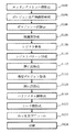
図1は、実施の形態1における半導体装置の製造方法の要部を表すフローチャートである。
図1において、実施の形態1の半導体装置の製造方法では、エッチングストッパ膜形成工程(S102)と、ポロジェン含有絶縁膜形成工程(S104)と、ポロジェン一部除去工程(S106)と、保護膜形成工程(S108)と、レジスト塗布工程(S109)と、レジストパターン形成工程(S110)と、開口部形成工程(S112)と、残留ポロジェン除去工程(S114)と、開口部形成工程(S116)と、バリアメタル膜形成工程(S118)と、シード膜形成工程(S120)と、めっき及びアニール工程(S122)と、研磨工程(S124)という一連の工程を実施する。
以下、実施の形態1について、図面を用いて説明する。
図1は、実施の形態1における半導体装置の製造方法の要部を表すフローチャートである。
図1において、実施の形態1の半導体装置の製造方法では、エッチングストッパ膜形成工程(S102)と、ポロジェン含有絶縁膜形成工程(S104)と、ポロジェン一部除去工程(S106)と、保護膜形成工程(S108)と、レジスト塗布工程(S109)と、レジストパターン形成工程(S110)と、開口部形成工程(S112)と、残留ポロジェン除去工程(S114)と、開口部形成工程(S116)と、バリアメタル膜形成工程(S118)と、シード膜形成工程(S120)と、めっき及びアニール工程(S122)と、研磨工程(S124)という一連の工程を実施する。
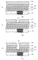
図2は、図1のフローチャートに対応して実施される工程を表す工程断面図である。
図2では、図1のエッチングストッパ膜形成工程(S102)から保護膜形成工程(S108)までを示している。
図2では、図1のエッチングストッパ膜形成工程(S102)から保護膜形成工程(S108)までを示している。
図2(a)において、エッチングストッパ膜形成工程(S102)として、基板200上に、化学気相成長(CVD)法によってエッチングストッパ膜210を例えば25nmの膜厚で形成する。エッチングストッパ膜の材料として、例えば、炭窒化シリコン(SiCN)、炭化シリコン(SiC)、或いは窒化シリコン(SiN)等が好適である。また、形成方法は、CVD法に限るものではなくその他の方法で成膜しても構わない。また、基板200として、例えば、直径300ミリのシリコンウェハを用いる。ここでは、基板200に金属配線202が形成されている場合を示している。また、金属配線202より下層のコンタクトプラグ層やデバイス部分等の図示は省略している。そして、基板200上には、その他の金属配線またはコンタクトプラグ等、図示しない各種の半導体素子あるいは構造を有する層が形成されていても構わない。或いは、その他の層が形成されていても構わない。
図2(b)において、ポロジェン含有絶縁膜形成工程(S104)として、エッチングストッパ膜210上に、PE−CVD法により膜中にポロジェン材料222を含有したSiOC膜220を例えば300nmの厚さで形成する。メチルジエトキシシラン(Methyl−di−ethoxy−silane)、アルファターピネン(alpha−terpinene:C10H16)、酸素(O2)、ヘリウム(He)からなる混合ガスを図示しないチャンバ内に流入し、チャンバ内の圧力を例えば1.3×10³Pa(10Torr)以下に維持した状態で、エッチングストッパ膜210が成膜された基板200を例えば250℃に加熱し、チャンバ内の図示しない下部電極及び上部電極に高周波電力を供給し、プラズマを発生させる。メチルジエトキシシランは主骨格成分形成用のガスであり、アルファターピネンはポロジェン成分形成用ガスである。これにより、エッチングストッパ膜210上に有機シロキサンを主骨格成分とするSiOC膜220が形成される。このとき、混合ガスに含まれるアルファターピネンがプラズマによって重合し、有機高分子が形成される。この有機高分子がポロジェン材料222であり、SiOC膜220中に均一に取り込まれる。
なお、主骨格成分形成用の有機シリコンガスとしては、ジメチルシラン(Di−Methyl−Silane)、トリメチルシラン(Tri−Methyl−Silane)、テトラメチルシラン(Tetra−Methyl−Silane)、ジメチルフェニルシラン(Di−Methyl−Phenyl−Silane)、トリメチルシリルアセチレン(Tri−Methyl−Silyl−Acetylene)、モノメチルジエトキシシラン(Mono−Methyl−Di−Ethoxy−Silane)、ジメチルジエトキシシラン(Di−Methyl−Di−Ethoxy−Silane)、テトラメチルシクロテトラシロキサン(Tetra−Methyl−Cyclo−Tetra−Siloxane)、及びオクタメチルシクロテトラシロキサン(Octa−Methyl−Cyclo−Tetra−Siloxane)の少なくとも1つを用いることができる。
また、ポロジェン成分形成用ガスとしては、メタン(Methane)、エチレン(Ethylene)、プロピレン(Propylene)、アルファターピネン(Alpha−Terpinene)、ガンマターピネン(Gamma−Terpinene)、及びリモーネン(Limonene)の少なくとも1つを用いることができる。
また、ここでは、CVD法でSiOC膜を形成しているが、形成方法はこれに限るものではない。例えば、ポロジェン材料を含有する溶液をスピンコートし熱処理して薄膜を形成するSOD(spin on dielectric coating)法を用いても好適である。SOD法で形成する低誘電率絶縁膜の材料としては、例えば、メチルシロセスキオキサン(methyl silsesquioxane:MSQ)を用いることができる。また、MSQの他に、例えば、ポリメチルシロキサン、ポリシロキサン、ハイドロジェンシロセスキオキサンなどのシロキサン骨格を有する膜、ポリアリーレンエーテル、ポリベンゾオキサゾール、ポリベンゾシクロブテンなどの有機樹脂を主成分とする膜、および多孔質シリカ膜などのポーラス膜からなる群から選択される少なくとも一種を用いて形成しても構わない。SOD法では、例えば、スピナーで成膜し、このウエハをホットプレート上で窒素雰囲気中でのベークを行なうことでポロジェン材料222が均一に含有された例えば有機シロキサンを主骨格成分とするSiOC膜220を形成することができる。いずれの低誘電率絶縁膜の材料を用いても、最終的に比誘電率が2.5未満の低誘電率を得ることができる。
図2(c)において、ポロジェン一部除去工程(S106)として、電子線照射を行ってSiOC膜220に含まれるポロジェン材料222の一部を除去する。また、電子線照射によってSiOC膜220における主骨格成分の硬化を適宜促進させる。具体的には、SiOC膜220が形成された基板200を図示しないチャンバ内部で例えば1.3×10³Pa(10Torr)以下に維持した状態で、例えば400℃に加熱する。次に、このチャンバ内部にアルゴン(Ar)ガスを流入し、チャンバ内部の圧力を一定に維持する。圧力が一定になった後、電子線140をSiOC膜220に照射する。ここでは、SiOC膜220内のすべてのポロジェン材料222を除去する従来の入射エネルギーよりも弱くした入射エネルギーで電子線140の照射を行なう。これにより、ポロジェン材料222の一部が気泡となって除去され、図2(c)に示すように、SiOC膜220の上面側部分よりも下面側部分の方がポロジェン材料222の濃度が濃い状態を形成することができる。ポロジェン材料222が除去された部分は、空孔224となる。よって、特に、SiOC膜220の上面側部分にポーラスSiOC膜が形成される。例えば、SiOC膜220の下半分より薄い膜厚でSiOC膜220の下面側にポロジェン材料222の濃度が濃い領域を形成すると好適である。
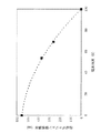
図3は、実施の形態1における電子線照射を行った際の炭素濃度と膜深さとの関係の一例を示す図である。
図3において、550nmの膜厚のポロジェン材料222が均一に含有されたSiOC膜220に対して、従来の入射エネルギーで電子線照射を行なった場合と30%低減した入射エネルギーで電子線照射を行なった場合での炭素濃度と膜深さとの関係を示している。ここでは、基準となる従来の入射エネルギーの一例として、電界強度を4.8kV/cm、照射電子量を100μC/cm2としている。図3では、2次イオン質量分離分析(SIMS分析)によるポーラスSiOC膜中炭素濃度プロファイル結果を示す。入射エネルギーを30%低減することでポーラスSiOC膜とエッチングストッパ膜210となるSiCN膜界面に約250nmの従来よりも濃度が順に高くなっていく領域が存在していることがわかる。その内、100nmについては従来との差が大きく広がり、特に、高炭素濃度領域であることがわかる。
図3において、550nmの膜厚のポロジェン材料222が均一に含有されたSiOC膜220に対して、従来の入射エネルギーで電子線照射を行なった場合と30%低減した入射エネルギーで電子線照射を行なった場合での炭素濃度と膜深さとの関係を示している。ここでは、基準となる従来の入射エネルギーの一例として、電界強度を4.8kV/cm、照射電子量を100μC/cm2としている。図3では、2次イオン質量分離分析(SIMS分析)によるポーラスSiOC膜中炭素濃度プロファイル結果を示す。入射エネルギーを30%低減することでポーラスSiOC膜とエッチングストッパ膜210となるSiCN膜界面に約250nmの従来よりも濃度が順に高くなっていく領域が存在していることがわかる。その内、100nmについては従来との差が大きく広がり、特に、高炭素濃度領域であることがわかる。
図4は、実施の形態1における電子線の電界強度の割合と残留ポロジェン領域の膜厚との関係の一例を示す図である。
図4において、550nmの膜厚のポロジェン材料222が均一に含有されたSiOC膜220に対して、従来の電子線の入射エネルギーを100%として、電界強度を下げた場合の残留ポロジェン領域の膜厚の一例を示す図である。例えば、図3と同様、入射エネルギーとして、電界強度を30%低減することでポーラスSiOC膜とエッチングストッパ膜210となるSiCN膜界面に約250nmのポロジェン残留領域が存在していることがわかる。これは、図3の従来よりも濃度が順に高くなっていく領域の膜厚とほぼ一致している。
図4において、550nmの膜厚のポロジェン材料222が均一に含有されたSiOC膜220に対して、従来の電子線の入射エネルギーを100%として、電界強度を下げた場合の残留ポロジェン領域の膜厚の一例を示す図である。例えば、図3と同様、入射エネルギーとして、電界強度を30%低減することでポーラスSiOC膜とエッチングストッパ膜210となるSiCN膜界面に約250nmのポロジェン残留領域が存在していることがわかる。これは、図3の従来よりも濃度が順に高くなっていく領域の膜厚とほぼ一致している。
このように、入射エネルギーを低減することで、SiOC膜220の下面側に高炭素濃度領域を生じさせ得ることを発明者等は見出した。そこで、この実験結果を踏まえて、照射電子の入射エネルギーを調整することによって深さ方向のポロジェン残留分布を制御して、ポーラスSiOC膜220とSiCN膜界面に炭素濃度の高い領域を形成する。このように積層膜にしなくても炭素濃度の異なる領域を単層膜(1つの膜)の中に形成することができる。そして、単層膜の中に炭素濃度の高い領域を形成することで1つの膜の中でエッチング選択比を変化させることができる。SiOC膜220の下部領域と上部領域の炭素濃度比は適宜調整すればよい。より好ましくはSiOC膜220の下部に上部より3倍以上の炭素濃度比を有する領域を形成するとよい。
図2(d)において、保護膜形成工程として、下部に高炭素濃度領域を有するポーラスSiOC膜220上に、CVD法を用いて保護膜230を例えば30nmの膜厚で形成する。保護膜230の材料として、SiN膜、SiO2膜、SiCN膜、SiC膜、或いはdenseSiCO膜が好適である。ここでは、ポーラスSiOC膜220とは組成が異なり、かつ炭素−炭素結合を主成分として持たない膜であればよい。後述する残留ポロジェン除去工程(S114)の際の紫外線照射は、炭素−炭素結合を破壊し、紫外線照射の際に後述するレジストマスクが除去されてしまうため、レジストマスクとポーラスSiOC膜220の間に、後述する開口部形成工程(S116)におけるマスク材となる保護膜230を1層以上形成しておくことが有効である。
ここで、保護膜230によっては、ポロジェン含有絶縁膜形成工程(S104)に引き続いて保護膜230を形成し、その後ポロジェン一部除去工程(S106)として電子線照射を行ないSiOC膜220に含まれるポロジェン材料222の一部を除去することもできる。保護膜230の膜密度や膜厚を調整することにより、保護膜230を通して気泡となったポロジェン材料222を除去することができる。この場合、ポロジェン一部除去工程(S106)におけるSiOC膜220への入射電子が保護膜230において減速されるため、結果的にSiOC膜220に対する電子線の入射エネルギーが弱められる。したがって、保護膜230で電子線の入射エネルギーが弱められる分を考慮して、電子線照射の際の電界強度は必要に応じて降下させればよい。
ここで、保護膜230によっては、ポロジェン含有絶縁膜形成工程(S104)に引き続いて保護膜230を形成し、その後ポロジェン一部除去工程(S106)として電子線照射を行ないSiOC膜220に含まれるポロジェン材料222の一部を除去することもできる。保護膜230の膜密度や膜厚を調整することにより、保護膜230を通して気泡となったポロジェン材料222を除去することができる。この場合、ポロジェン一部除去工程(S106)におけるSiOC膜220への入射電子が保護膜230において減速されるため、結果的にSiOC膜220に対する電子線の入射エネルギーが弱められる。したがって、保護膜230で電子線の入射エネルギーが弱められる分を考慮して、電子線照射の際の電界強度は必要に応じて降下させればよい。
また、保護膜230は絶縁膜の代わりに、タンタル(Ta)、チタン(Ti)、ルテニウム(Ru)、タングステン(W)、ジルコニウム(Zr)、アルミニウム(Al)、ニオブ(Nb)等の金属、或いは、窒化タンタル(TaN)、窒化チタン(TiN)、窒化タングステン(WN)等に代表されるこれらの金属の窒化物、或いはこれらの金属の合金を材料として用いることができる。これらの金属膜の堆積方法としては、PVD法、原子層気相成長(atomic layer deposition:ALD、或いは、atomic layer chemical vapor deposition:ALCVD)法、又はCVD法などを用いることができる。特に、保護膜230として、金属膜を用いる場合には、後述するバリアメタル膜に使用する材料と同一の材料を用いるとより好適である。
図5は、図1のフローチャートに対応して実施される工程を表す工程断面図である。
図5では、図1のレジスト塗布工程(S109)から開口部形成工程(S112)までを示している。
図5では、図1のレジスト塗布工程(S109)から開口部形成工程(S112)までを示している。
図5(a)において、レジスト塗布工程(S109)として、保護膜230上にレジスト膜232を塗布する。
図5(b)において、レジストパターン形成工程(S110)として、露光工程等のリソグラフィー工程を経て保護膜230上にヴィアホールパターンとなるレジストパターンを形成し、選択的に開口部150を形成する。
図5(c)において、開口部形成工程(S112)として、レジストパターンをマスクとして、露出した保護膜230とその下層のポーラスSiOC膜220を異方性エッチング法により選択的にエッチングして、ヴィアホールの上段部分となる開口部152を形成する。このときは、エッチングストッパ膜210に到達するまでエッチングするのではなく、ポーラスSiOC膜220の底部の高炭素濃度領域を残すように途中でエッチングを停止して、開口部152を形成する。ここでは、ポーラスSiOC膜220のエッチング速度が膜中の炭素濃度に依存する条件を用いる。エッチングガスとして、フッ素系のガス、例えば1種以上のCxHyFz(x,z:1以上の整数、y:0以上の整数)ガスと不活性ガスを用いると好適である。異方性エッチング法により除去することで、基板200の表面に対し、略垂直に開口部152を形成することができる。例えば、一例として、反応性イオンエッチング(RIE)法により開口部152を形成すればよい。
上述したポロジェン一部除去工程(S106)によって、ポーラスSiOC膜220中の上部は低炭素濃度領域となっており、他方、下部は高炭素濃度領域となっているため、高炭素濃度領域でエッチング速度が低下し、図5(c)に示すようにポロジェン材料222が多く残留する高炭素濃度領域がエッチングストッパとなってエッチングを停止させることができる。その際に、パターン面積密度の違いにより先に高炭素濃度領域に到達したパターン箇所が高炭素濃度領域をエッチングしている間に残りのパターン箇所が高炭素濃度領域に到達するので、パターン面積密度の違いによるエッチング量の差を解消或いは縮小することができる。
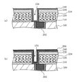
図6は、図1のフローチャートに対応して実施される工程を表す工程断面図である。
図6では、図1の残留ポロジェン除去工程(S114)から開口部形成工程(S116)までを示している。
図6では、図1の残留ポロジェン除去工程(S114)から開口部形成工程(S116)までを示している。
図6(a)において、残留ポロジェン除去工程(S114)として、紫外線照射を行ってポーラスSiOC膜220に含まれる残留ポロジェン材料222を除去する。ポーラスSiOC膜220が形成された基板200を図示しないチャンバ内部で例えば1.3×10³Pa(10Torr)以下に維持した状態で、例えば400℃に加熱する。次に、このチャンバ内部にArガスを流入し、チャンバ内部の圧力を一定に維持する。圧力が一定になった後、紫外線142を保護膜230で保護されたポーラスSiOC膜220に照射する。ここでは、200nmから600nmの波長領域を持つ紫外線142を保護膜230で保護されたポーラスSiOC膜220に照射する。これにより、ポロジェン材料222の残部が気泡となって除去され、図6(a)に示すように、ポーラスSiOC膜220の残留していたポロジェン材料222、特にエッチングストッパ膜210界面付近の下面側部分に残留していたポロジェン材料222が除去される。ポロジェン材料222が除去された部分は、空孔224となる。これにより、全体に均一な空孔224が散りばめられたポーラスSiOC膜220を形成することができる。また、紫外線照射により炭素−炭素結合が破壊され、レジスト膜232も一緒に除去することができる。
なお、残留ポロジェン材料222を除去することに代え、或いは加えて、紫外線照射によってポロジェン成分どうし、またはポロジェン成分と主骨格成分との重合反応を生じさせてもよい。例えば、保護膜230の膜密度、膜厚を調整して、気泡となったポロジェン材料222をも通しにくく設定することにより、開口部152の近傍を除きポロジェン材料222は除去され難く、気泡となった後にポーラスSiOC膜220中で重合反応を起こさせることができる。この場合、ポロジェン材料222のすべてを除去していない分多少誘電率は増大するが、残留ポロジェン材料222の重合反応に起因して膜質の良好なポーラスSiOC膜220が得られる点で有効である。
なお、残留ポロジェン材料222を除去することに代え、或いは加えて、紫外線照射によってポロジェン成分どうし、またはポロジェン成分と主骨格成分との重合反応を生じさせてもよい。例えば、保護膜230の膜密度、膜厚を調整して、気泡となったポロジェン材料222をも通しにくく設定することにより、開口部152の近傍を除きポロジェン材料222は除去され難く、気泡となった後にポーラスSiOC膜220中で重合反応を起こさせることができる。この場合、ポロジェン材料222のすべてを除去していない分多少誘電率は増大するが、残留ポロジェン材料222の重合反応に起因して膜質の良好なポーラスSiOC膜220が得られる点で有効である。
また、ここでは、紫外線照射を行なっているが、これに限るものではない。例えば、電子線照射、加熱処理、酸化性ガス処理、還元性ガス処理、或いは薬液処理等で残留ポロジェン材料222を除去等しても好適である。また、加熱処理と電子線照射、加熱処理と酸化性ガス処理、或いは加熱処理と還元性ガス処理といった組み合わせ等、これら各処理を適宜組み合わせて用いてもよい。例えば、電子線照射では、ポロジェン一部除去工程(S106)における入射エネルギーの低減をせずに照射すればよい。また、加熱処理では、350℃以上で加熱すればよい。酸化性ガス処理では、例えば、基板200を加熱した上で、酸素(O2)、一酸化炭素(CO)、二酸化炭素(CO2)、或いはそれらの混合ガスに曝露させればよい。また、還元性ガス処理では、例えば、基板200を加熱した上で、水素(H2)、アンモニア(NH3)、或いはNH3とヒドラジン(N2H2)の混合ガスに曝露させればよい。ここで、上述したように、本実施の形態では、一例として、加熱処理と紫外線照射とを組み合わせた場合について説明した。このように、加熱処理と紫外線照射の組み合わせなど複数の処理を組み合わせることで、処理時間を短縮させることができる。処理時間を短縮させることにより下地の配線層のダメージを低減することができる。
図6(b)において、開口部形成工程(S116)として、保護膜230をハードマスクとして、露出したポーラスSiOC膜220の開口部152の底部を異方性エッチング法により選択的にエッチングして除去し、ヴィアホールの下段部分まで続く開口部154を形成する。ここでは、エッチングストッパ膜210をエッチングストッパとして、ポーラスSiOC膜220の十分なエッチング選択比が得られるような条件でエッチングを行なう。エッチングガスとして、フッ素系のガス、例えば1種以上のCxHyFz(x,z:1以上の整数、y:0以上の整数)ガスと不活性ガスを用いると好適である。また、異方性エッチング法により除去することで、基板200の表面に対し、略垂直に開口部154を形成することができる。例えば、一例として、RIE法により開口部154を形成すればよい。
このとき、レジスト膜232より薄くすることが可能な保護膜230をハードマスクとしてエッチングすることで、開口部154の寸法精度を向上させることができる。また、パターン面積密度の違いによるエッチング量の差は、既に解消或いは縮小されており、さらに、残った開口部152の底部の膜厚も薄いためエッチング量が少ない。しかも、残留ポロジェン除去工程(S114)における紫外線の照射によって、開口部152の底部のポーラスSiOC膜220のエッチング速度は高められているので、パターン面積密度の違いにより先にエッチングストッパ膜210に到達したパターン箇所がエッチングストッパ膜210をエッチングしている間に残りのパターン箇所をエッチングストッパ膜210に到達させることができる。よって、一部のパターン箇所がエッチングストッパ膜210を突き破って、その下層の基板200を不必要にエッチングしてしまうことを防止できる。そして、その後に、残ったエッチングストッパ膜210をエッチングすることで図6(c)に示すように開口部154が完成する。
このとき、レジスト膜232より薄くすることが可能な保護膜230をハードマスクとしてエッチングすることで、開口部154の寸法精度を向上させることができる。また、パターン面積密度の違いによるエッチング量の差は、既に解消或いは縮小されており、さらに、残った開口部152の底部の膜厚も薄いためエッチング量が少ない。しかも、残留ポロジェン除去工程(S114)における紫外線の照射によって、開口部152の底部のポーラスSiOC膜220のエッチング速度は高められているので、パターン面積密度の違いにより先にエッチングストッパ膜210に到達したパターン箇所がエッチングストッパ膜210をエッチングしている間に残りのパターン箇所をエッチングストッパ膜210に到達させることができる。よって、一部のパターン箇所がエッチングストッパ膜210を突き破って、その下層の基板200を不必要にエッチングしてしまうことを防止できる。そして、その後に、残ったエッチングストッパ膜210をエッチングすることで図6(c)に示すように開口部154が完成する。
図7は、従来の手法で形成した開口部と実施の形態1の手法で形成した開口部の違いを説明するための概念図である。
従来は、SiOC膜120中のポロジェンをすべて除去して空孔124を均一に形成した後に、レジスト膜130をパターンとして開口部を形成するため、図7(a)に示すように、エッチングストッパ膜110を突き破って基板100内の配線102側面を過剰にエッチングしてしまう恐れがあった。これに対し、実施の形態1では、ポロジェン材料222がほぼ均一に分布するSiOC膜220を形成した後に、電子線照射を行なうことで、同一膜内のポロジェン材料222の分布を変化させることができる。その結果、高炭素濃度領域をSiOC膜220の下部に形成することができる。そして、SiOC膜220の下部のポロジェンの濃度を濃くした状態で開口部の途中までのエッチングを行ない、次いでSiOC膜220中のポロジェン材料222の残部を除去した後に保護膜230をマスクとして開口部の残りの底部をエッチングする。これにより、図7(b)に示すように、エッチングストッパ膜210を突き破って基板200内の配線202側面を過剰にエッチングしてしまうことを防止できる。よって、エッチングストッパ膜210の膜厚を厚くする必要を無くし、配線間容量を上昇させることなくヴィアプラグ形状の加工制御を容易にすることができる。或いはエッチングストッパ膜210の膜厚を薄くすることができ、配線間容量を低減させることができる。
従来は、SiOC膜120中のポロジェンをすべて除去して空孔124を均一に形成した後に、レジスト膜130をパターンとして開口部を形成するため、図7(a)に示すように、エッチングストッパ膜110を突き破って基板100内の配線102側面を過剰にエッチングしてしまう恐れがあった。これに対し、実施の形態1では、ポロジェン材料222がほぼ均一に分布するSiOC膜220を形成した後に、電子線照射を行なうことで、同一膜内のポロジェン材料222の分布を変化させることができる。その結果、高炭素濃度領域をSiOC膜220の下部に形成することができる。そして、SiOC膜220の下部のポロジェンの濃度を濃くした状態で開口部の途中までのエッチングを行ない、次いでSiOC膜220中のポロジェン材料222の残部を除去した後に保護膜230をマスクとして開口部の残りの底部をエッチングする。これにより、図7(b)に示すように、エッチングストッパ膜210を突き破って基板200内の配線202側面を過剰にエッチングしてしまうことを防止できる。よって、エッチングストッパ膜210の膜厚を厚くする必要を無くし、配線間容量を上昇させることなくヴィアプラグ形状の加工制御を容易にすることができる。或いはエッチングストッパ膜210の膜厚を薄くすることができ、配線間容量を低減させることができる。
図8は、図1のフローチャートに対応して実施される工程を表す工程断面図である。
図8では、図1のバリアメタル膜形成工程(S118)からシード膜形成工程(S120)までを示している。
図8では、図1のバリアメタル膜形成工程(S118)からシード膜形成工程(S120)までを示している。
図8(a)において、バリアメタル膜形成工程(S118)として、エッチングにより形成された開口部154内面上及び保護膜230表面上に導電性材料の一例となるバリアメタル材料を用いたバリアメタル膜240を形成する。スパッタ法を用いるスパッタリング装置内でTaN膜を例えば膜厚5nm堆積し、バリアメタル膜240を形成する。バリアメタル材料の堆積方法としては、PVD法に限らず、原子層気相成長法やCVD法などを用いることができる。PVD法を用いる場合より被覆率を良くすることができる。また、バリアメタル膜の材料としては、TaNの他、Ta、Ti、W、TiN、WNもしくはTaとTaN等これらを組合せて用いた積層膜であっても構わない。或いは、保護膜230を金属膜で形成する場合と同様、Ru、Zr、Al、Nb等の金属、或いはこれらの金属の窒化物を用いることができる。
図8(b)において、シード膜形成工程(S120)として、スパッタ等の物理気相成長(PVD)法により、次の工程である電解めっき工程のカソード極となるCu薄膜をシード膜250としてバリアメタル膜240が形成された開口部154内壁及び基板200表面に堆積(形成)させる。
図9は、図1のフローチャートに対応して実施される工程を表す工程断面図である。
図9では、図1のめっき及びアニール工程(S122)から研磨工程(S124)までを示している。
図9では、図1のめっき及びアニール工程(S122)から研磨工程(S124)までを示している。
図9(a)において、めっき及びアニール工程(S122)として、シード膜250をカソード極として、電解めっき等の電気化学成長法により導電性材料の一例となるCu膜260をシード膜250が形成された開口部154及び基板200表面に堆積させる。ここでは、例えば、膜厚200nmのCu膜260を堆積させ、アニール処理を例えば250℃の温度で30分間行なう。
図9(b)において、研磨工程(S124)として、CMP法によって、基板200の表面を研磨して、開口部以外に表面に堆積した配線層となるシード膜250を含むCu膜260とバリアメタル膜240と保護膜230を研磨除去する。このように導電性材料を研磨して、バリアメタル膜240が内面上に形成されている開口部154に導電性材料を選択的に残置させる。その結果、図9(b)に示すように平坦化することができる。以上によりCu配線202上にヴィアプラグを形成することができる。
ここで、保護膜230として絶縁膜を用いた場合には、研磨工程(S124)において、SiOC膜220上に保護膜230を残置させても構わない。他方、保護膜230として金属膜を用いる場合には、保護膜230を研磨除去する。その際、特に、保護膜230がバリアメタル膜240と同材料で形成されている場合には、バリアメタル膜240と金属膜の保護膜230を一緒に研磨することができる。ここで、バリアメタル膜240を研磨する際には開口部154に堆積するCu膜260も一緒に研磨することになるので、研磨に使用するスラリ等の研磨液や研磨後の洗浄に用いる洗浄液はバリアメタル材とCuという異種金属間に電位差が生じることによる腐食が生じないように調整されている。これに対し、保護膜230の材料をバリアメタル材と異なる材料とすると3種の異種材料について腐食しないように研磨液や洗浄液を調整する必要が生じてしまう。3種の異種材料への調整は非常に難しい。そこで、バリアメタル膜240と金属膜の保護膜230を同じ材料にする場合には、調整が容易な2種の異種材料への調整で済ますことができる。
以上の説明において、上記各実施の形態における配線層の材料として、Cu以外に、Cu−Sn合金、Cu−Ti合金、Cu−Al合金等の、半導体産業で用いられるCuを主成分とする材料を用いても同様の効果が得られる。
以上、具体例を参照しつつ実施の形態について説明した。しかし、本発明は、これらの具体例に限定されるものではない。例えば、上述した例では、ヴィアホールを形成する場合について説明したが、トレンチを形成する場合でも同様に適用することができる。また、CMP法以外の方法で保護膜230を除去しても構わない。例えば、薬液処理にて保護膜230を除去しても構わない。
さらに、層間絶縁膜の膜厚や、開口部のサイズ、形状、数などについても、半導体集積回路や各種の半導体素子において必要とされるものを適宜選択して用いることができる。
その他、本発明の要素を具備し、当業者が適宜設計変更しうる全ての半導体装置及び半導体装置の製造方法は、本発明の範囲に包含される。
また、説明の簡便化のために、半導体産業で通常用いられる手法、例えば、フォトリソグラフィプロセス、処理前後のクリーニング等は省略しているが、それらの手法が含まれ得ることは言うまでもない。
140 電子線、142 紫外線、150,152,154 開口部、200 基板、210 エッチングストッパ膜、220 SiOC膜、222 ポロジェン材料、230 保護膜、232 レジスト膜
Claims (5)
- 基体上にポロジェン材料を含む絶縁膜を形成する工程と、
前記絶縁膜の下面側部分が上面側部分よりも前記ポロジェン材料の濃度が相対的に濃くなるように、前記絶縁膜に含まれる前記ポロジェン材料の一部を除去する工程と、
前記ポロジェン材料の一部が除去された前記絶縁膜に前記絶縁膜の底部を残すように開口部を形成する工程と、
前記絶縁膜に含まれる前記ポロジェン材料の残部を除去または重合させる工程と、
前記ポロジェン材料の残部を除去または重合させた後に前記開口部の前記底部をエッチングする工程と、
を備えたことを特徴とする半導体装置の製造方法。 - 前記絶縁膜に電子線を照射することにより前記ポロジェン材料の一部を除去することを特徴とする請求項1記載の半導体装置の製造方法。
- 前記絶縁膜上に所定の膜を形成する工程をさらに備え、
前記所定の膜上に形成したレジストパターンをマスクとして、前記絶縁膜の底部を残すように前記開口部が形成され、
前記レジストパターンが除去された後前記所定の膜をマスクとして、前記開口部の前記底部がエッチングされることを特徴とする請求項1記載の半導体装置の製造方法。 - 前記所定の膜が上面に形成された前記絶縁膜に紫外線を照射することにより前記ポロジェン材料の残部を除去または重合させることを特徴とする請求項3記載の半導体装置の製造方法。
- 前記紫外線を照射することにより前記所定の膜上に形成した前記レジストパターンが除去されることを特徴とする請求項4記載の半導体装置の製造方法。
Priority Applications (3)
| Application Number | Priority Date | Filing Date | Title |
|---|---|---|---|
| JP2008031811A JP2009194072A (ja) | 2008-02-13 | 2008-02-13 | 半導体装置の製造方法 |
| TW098100865A TW200949931A (en) | 2008-02-13 | 2009-01-10 | Method for fabricating a semiconductor device |
| US12/370,055 US7795142B2 (en) | 2008-02-13 | 2009-02-12 | Method for fabricating a semiconductor device |
Applications Claiming Priority (1)
| Application Number | Priority Date | Filing Date | Title |
|---|---|---|---|
| JP2008031811A JP2009194072A (ja) | 2008-02-13 | 2008-02-13 | 半導体装置の製造方法 |
Publications (2)
| Publication Number | Publication Date |
|---|---|
| JP2009194072A true JP2009194072A (ja) | 2009-08-27 |
| JP2009194072A5 JP2009194072A5 (ja) | 2010-04-08 |
Family
ID=40939243
Family Applications (1)
| Application Number | Title | Priority Date | Filing Date |
|---|---|---|---|
| JP2008031811A Abandoned JP2009194072A (ja) | 2008-02-13 | 2008-02-13 | 半導体装置の製造方法 |
Country Status (3)
| Country | Link |
|---|---|
| US (1) | US7795142B2 (ja) |
| JP (1) | JP2009194072A (ja) |
| TW (1) | TW200949931A (ja) |
Cited By (2)
| Publication number | Priority date | Publication date | Assignee | Title |
|---|---|---|---|---|
| JP2012138503A (ja) * | 2010-12-27 | 2012-07-19 | Fujifilm Corp | 多孔質絶縁膜及びその製造方法 |
| JP2013528928A (ja) * | 2010-03-29 | 2013-07-11 | 東京エレクトロン株式会社 | 低誘電率絶縁体を統合するための方法 |
Families Citing this family (11)
| Publication number | Priority date | Publication date | Assignee | Title |
|---|---|---|---|---|
| KR20090116477A (ko) * | 2008-05-07 | 2009-11-11 | 삼성전자주식회사 | 초저유전막을 포함하는 반도체 소자의 제조 방법 |
| JP5985406B2 (ja) * | 2013-01-31 | 2016-09-06 | 株式会社東芝 | 半導体装置の製造方法及び半導体装置の製造装置 |
| US9165822B2 (en) * | 2013-03-11 | 2015-10-20 | Taiwan Semiconductor Manufacturing Company, Ltd. | Semiconductor devices and methods of forming same |
| KR101998788B1 (ko) | 2013-04-22 | 2019-07-11 | 삼성전자주식회사 | 반도체 장치 및 그 제조 방법 |
| US9054052B2 (en) * | 2013-05-28 | 2015-06-09 | Global Foundries Inc. | Methods for integration of pore stuffing material |
| JP2016018879A (ja) | 2014-07-08 | 2016-02-01 | 株式会社東芝 | 半導体装置および半導体装置の製造方法 |
| CN104617036B (zh) * | 2015-01-14 | 2018-07-27 | 华天科技(昆山)电子有限公司 | 晶圆级芯片尺寸封装中通孔互连的制作方法 |
| KR102460075B1 (ko) * | 2016-01-27 | 2022-10-31 | 삼성전자주식회사 | 반도체 장치 및 반도체 장치의 제조 방법 |
| US9859154B2 (en) * | 2016-03-11 | 2018-01-02 | Taiwan Semiconductor Manufacturing Co., Ltd. | Structure and formation method of interconnect structure of semiconductor device |
| KR102616489B1 (ko) | 2016-10-11 | 2023-12-20 | 삼성전자주식회사 | 반도체 장치 제조 방법 |
| US10950426B2 (en) * | 2018-08-14 | 2021-03-16 | Taiwan Semiconductor Manufacturing Co., Ltd. | Dielectric layer, interconnection structure using the same, and manufacturing method thereof |
Family Cites Families (10)
| Publication number | Priority date | Publication date | Assignee | Title |
|---|---|---|---|---|
| US6528409B1 (en) * | 2002-04-29 | 2003-03-04 | Advanced Micro Devices, Inc. | Interconnect structure formed in porous dielectric material with minimized degradation and electromigration |
| US6964919B2 (en) * | 2002-08-12 | 2005-11-15 | Intel Corporation | Low-k dielectric film with good mechanical strength |
| JP2004274020A (ja) * | 2002-09-24 | 2004-09-30 | Rohm & Haas Electronic Materials Llc | 電子デバイス製造 |
| US7125793B2 (en) * | 2003-12-23 | 2006-10-24 | Intel Corporation | Method for forming an opening for an interconnect structure in a dielectric layer having a photosensitive material |
| US7557035B1 (en) * | 2004-04-06 | 2009-07-07 | Advanced Micro Devices, Inc. | Method of forming semiconductor devices by microwave curing of low-k dielectric films |
| US7585722B2 (en) * | 2006-01-10 | 2009-09-08 | International Business Machines Corporation | Integrated circuit comb capacitor |
| US20070232046A1 (en) * | 2006-03-31 | 2007-10-04 | Koji Miyata | Damascene interconnection having porous low K layer with improved mechanical properties |
| JP4419025B2 (ja) * | 2006-09-04 | 2010-02-24 | ソニー株式会社 | 半導体装置の製造方法 |
| US7723226B2 (en) * | 2007-01-17 | 2010-05-25 | Taiwan Semiconductor Manufacturing Company, Ltd. | Interconnects containing bilayer porous low-k dielectrics using different porogen to structure former ratio |
| WO2008094792A1 (en) * | 2007-01-29 | 2008-08-07 | Applied Materials, Inc. | Novel air gap integration scheme |
-
2008
- 2008-02-13 JP JP2008031811A patent/JP2009194072A/ja not_active Abandoned
-
2009
- 2009-01-10 TW TW098100865A patent/TW200949931A/zh unknown
- 2009-02-12 US US12/370,055 patent/US7795142B2/en not_active Expired - Fee Related
Cited By (2)
| Publication number | Priority date | Publication date | Assignee | Title |
|---|---|---|---|---|
| JP2013528928A (ja) * | 2010-03-29 | 2013-07-11 | 東京エレクトロン株式会社 | 低誘電率絶縁体を統合するための方法 |
| JP2012138503A (ja) * | 2010-12-27 | 2012-07-19 | Fujifilm Corp | 多孔質絶縁膜及びその製造方法 |
Also Published As
| Publication number | Publication date |
|---|---|
| TW200949931A (en) | 2009-12-01 |
| US20090203201A1 (en) | 2009-08-13 |
| US7795142B2 (en) | 2010-09-14 |
Similar Documents
| Publication | Publication Date | Title |
|---|---|---|
| JP2009194072A (ja) | 半導体装置の製造方法 | |
| JP4679193B2 (ja) | 半導体装置の製造方法及び半導体装置 | |
| TWI528454B (zh) | 半導體裝置及半導體裝置之製造方法 | |
| TWI304228B (en) | Method for forming semiconductor device having low-k dielectric layer | |
| US20100102452A1 (en) | Method for fabricating semiconductor device and semiconductor device | |
| JP4194508B2 (ja) | 半導体装置の製造方法 | |
| US6998216B2 (en) | Mechanically robust interconnect for low-k dielectric material using post treatment | |
| JP2008288234A (ja) | 半導体装置及び半導体装置の製造方法 | |
| US20070249164A1 (en) | Method of fabricating an interconnect structure | |
| JP2004055781A (ja) | 半導体装置の製造方法 | |
| JP5823359B2 (ja) | 半導体装置の製造方法 | |
| JP2007116167A (ja) | 特徴画成部を形成する方法 | |
| JP2008263097A (ja) | 半導体装置及び半導体装置の製造方法 | |
| JP2006222171A (ja) | 絶縁膜の形成方法、多層構造の形成方法および半導体装置の製造方法 | |
| JP2005340460A (ja) | 半導体装置の形成方法 | |
| JP2005203568A (ja) | 半導体装置の製造方法及び半導体装置 | |
| JP2010165760A (ja) | 半導体装置及び半導体装置の製造方法 | |
| JP2005340601A (ja) | 半導体装置の製造方法及び半導体装置 | |
| JP4447433B2 (ja) | 半導体装置の製造方法及び半導体装置 | |
| JP2006156519A (ja) | 半導体装置の製造方法 | |
| JP2006049534A (ja) | 半導体装置の製造方法及び半導体装置 | |
| JP4643975B2 (ja) | 半導体装置の製造方法 | |
| JP2008053308A (ja) | 半導体装置の製造方法およびプラズマ処理装置 | |
| JP2005340604A (ja) | 半導体装置の製造方法 | |
| JP2006060011A (ja) | 半導体装置の製造方法 |
Legal Events
| Date | Code | Title | Description |
|---|---|---|---|
| A521 | Written amendment |
Free format text: JAPANESE INTERMEDIATE CODE: A523 Effective date: 20100223 |
|
| A621 | Written request for application examination |
Free format text: JAPANESE INTERMEDIATE CODE: A621 Effective date: 20100223 |
|
| A762 | Written abandonment of application |
Free format text: JAPANESE INTERMEDIATE CODE: A762 Effective date: 20120614 |