EP4501651A2 - Druckkassette und drucker - Google Patents
Druckkassette und drucker Download PDFInfo
- Publication number
- EP4501651A2 EP4501651A2 EP24219495.9A EP24219495A EP4501651A2 EP 4501651 A2 EP4501651 A2 EP 4501651A2 EP 24219495 A EP24219495 A EP 24219495A EP 4501651 A2 EP4501651 A2 EP 4501651A2
- Authority
- EP
- European Patent Office
- Prior art keywords
- case portion
- case
- tape
- gear
- printing cassette
- Prior art date
- Legal status (The legal status is an assumption and is not a legal conclusion. Google has not performed a legal analysis and makes no representation as to the accuracy of the status listed.)
- Pending
Links
Images


Classifications
-
- B—PERFORMING OPERATIONS; TRANSPORTING
- B41—PRINTING; LINING MACHINES; TYPEWRITERS; STAMPS
- B41J—TYPEWRITERS; SELECTIVE PRINTING MECHANISMS, i.e. MECHANISMS PRINTING OTHERWISE THAN FROM A FORME; CORRECTION OF TYPOGRAPHICAL ERRORS
- B41J15/00—Devices or arrangements of selective printing mechanisms, e.g. ink-jet printers or thermal printers, specially adapted for supporting or handling copy material in continuous form, e.g. webs
- B41J15/04—Supporting, feeding, or guiding devices; Mountings for web rolls or spindles
- B41J15/042—Supporting, feeding, or guiding devices; Mountings for web rolls or spindles for loading rolled-up continuous copy material into printers, e.g. for replacing a used-up paper roll; Point-of-sale printers with openable casings allowing access to the rolled-up continuous copy material
-
- B—PERFORMING OPERATIONS; TRANSPORTING
- B41—PRINTING; LINING MACHINES; TYPEWRITERS; STAMPS
- B41J—TYPEWRITERS; SELECTIVE PRINTING MECHANISMS, i.e. MECHANISMS PRINTING OTHERWISE THAN FROM A FORME; CORRECTION OF TYPOGRAPHICAL ERRORS
- B41J15/00—Devices or arrangements of selective printing mechanisms, e.g. ink-jet printers or thermal printers, specially adapted for supporting or handling copy material in continuous form, e.g. webs
- B41J15/04—Supporting, feeding, or guiding devices; Mountings for web rolls or spindles
- B41J15/044—Cassettes or cartridges containing continuous copy material, tape, for setting into printing devices
-
- B—PERFORMING OPERATIONS; TRANSPORTING
- B41—PRINTING; LINING MACHINES; TYPEWRITERS; STAMPS
- B41J—TYPEWRITERS; SELECTIVE PRINTING MECHANISMS, i.e. MECHANISMS PRINTING OTHERWISE THAN FROM A FORME; CORRECTION OF TYPOGRAPHICAL ERRORS
- B41J15/00—Devices or arrangements of selective printing mechanisms, e.g. ink-jet printers or thermal printers, specially adapted for supporting or handling copy material in continuous form, e.g. webs
- B41J15/04—Supporting, feeding, or guiding devices; Mountings for web rolls or spindles
- B41J15/046—Supporting, feeding, or guiding devices; Mountings for web rolls or spindles for the guidance of continuous copy material, e.g. for preventing skewed conveyance of the continuous copy material
-
- B—PERFORMING OPERATIONS; TRANSPORTING
- B41—PRINTING; LINING MACHINES; TYPEWRITERS; STAMPS
- B41J—TYPEWRITERS; SELECTIVE PRINTING MECHANISMS, i.e. MECHANISMS PRINTING OTHERWISE THAN FROM A FORME; CORRECTION OF TYPOGRAPHICAL ERRORS
- B41J17/00—Mechanisms for manipulating page-width impression-transfer material, e.g. carbon paper
- B41J17/32—Detachable carriers or holders for impression-transfer material mechanism
-
- B—PERFORMING OPERATIONS; TRANSPORTING
- B41—PRINTING; LINING MACHINES; TYPEWRITERS; STAMPS
- B41J—TYPEWRITERS; SELECTIVE PRINTING MECHANISMS, i.e. MECHANISMS PRINTING OTHERWISE THAN FROM A FORME; CORRECTION OF TYPOGRAPHICAL ERRORS
- B41J2/00—Typewriters or selective printing mechanisms characterised by the printing or marking process for which they are designed
- B41J2/315—Typewriters or selective printing mechanisms characterised by the printing or marking process for which they are designed characterised by selective application of heat to a heat sensitive printing or impression-transfer material
- B41J2/32—Typewriters or selective printing mechanisms characterised by the printing or marking process for which they are designed characterised by selective application of heat to a heat sensitive printing or impression-transfer material using thermal heads
- B41J2/325—Typewriters or selective printing mechanisms characterised by the printing or marking process for which they are designed characterised by selective application of heat to a heat sensitive printing or impression-transfer material using thermal heads by selective transfer of ink from ink carrier, e.g. from ink ribbon or sheet
-
- B—PERFORMING OPERATIONS; TRANSPORTING
- B41—PRINTING; LINING MACHINES; TYPEWRITERS; STAMPS
- B41J—TYPEWRITERS; SELECTIVE PRINTING MECHANISMS, i.e. MECHANISMS PRINTING OTHERWISE THAN FROM A FORME; CORRECTION OF TYPOGRAPHICAL ERRORS
- B41J3/00—Typewriters or selective printing or marking mechanisms characterised by the purpose for which they are constructed
- B41J3/36—Typewriters or selective printing or marking mechanisms characterised by the purpose for which they are constructed for portability, i.e. hand-held printers or laptop printers
-
- B—PERFORMING OPERATIONS; TRANSPORTING
- B41—PRINTING; LINING MACHINES; TYPEWRITERS; STAMPS
- B41J—TYPEWRITERS; SELECTIVE PRINTING MECHANISMS, i.e. MECHANISMS PRINTING OTHERWISE THAN FROM A FORME; CORRECTION OF TYPOGRAPHICAL ERRORS
- B41J32/00—Ink-ribbon cartridges
-
- B—PERFORMING OPERATIONS; TRANSPORTING
- B41—PRINTING; LINING MACHINES; TYPEWRITERS; STAMPS
- B41J—TYPEWRITERS; SELECTIVE PRINTING MECHANISMS, i.e. MECHANISMS PRINTING OTHERWISE THAN FROM A FORME; CORRECTION OF TYPOGRAPHICAL ERRORS
- B41J33/00—Apparatus or arrangements for feeding ink ribbons or like character-size impression-transfer material
- B41J33/14—Ribbon-feed devices or mechanisms
- B41J33/16—Ribbon-feed devices or mechanisms with drive applied to spool or spool spindle
- B41J33/22—Ribbon-feed devices or mechanisms with drive applied to spool or spool spindle by gears or pulleys
-
- B—PERFORMING OPERATIONS; TRANSPORTING
- B41—PRINTING; LINING MACHINES; TYPEWRITERS; STAMPS
- B41J—TYPEWRITERS; SELECTIVE PRINTING MECHANISMS, i.e. MECHANISMS PRINTING OTHERWISE THAN FROM A FORME; CORRECTION OF TYPOGRAPHICAL ERRORS
- B41J15/00—Devices or arrangements of selective printing mechanisms, e.g. ink-jet printers or thermal printers, specially adapted for supporting or handling copy material in continuous form, e.g. webs
- B41J15/04—Supporting, feeding, or guiding devices; Mountings for web rolls or spindles
-
- B—PERFORMING OPERATIONS; TRANSPORTING
- B65—CONVEYING; PACKING; STORING; HANDLING THIN OR FILAMENTARY MATERIAL
- B65H—HANDLING THIN OR FILAMENTARY MATERIAL, e.g. SHEETS, WEBS, CABLES
- B65H2405/00—Parts for holding the handled material
- B65H2405/10—Cassettes, holders, bins, decks, trays, supports or magazines for sheets stacked substantially horizontally
- B65H2405/11—Parts and details thereof
Definitions
- the present disclosure relates to a printing cassette and a printer.
- Patent Literature 1 JP2010-234772A
- the above-described cassette is provided with a gear for transmitting a driving force to the inside of the cassette or a gear for transmitting a driving force from the cassette to the outside thereof.
- a gear for transmitting a driving force to the inside of the cassette or a gear for transmitting a driving force from the cassette to the outside thereof.
- the gear is easily damaged when the cassette is dropped and collides with a surface of a floor or somewhere.
- One aspect of the present disclosure is to provide a printing cassette that can reduce damage to a gear that transmits a driving force.
- One aspect of the present disclosure is a printing cassette including: a case including a first case portion, a second case portion, and a third case portion; a first tape, at least a portion of which is accommodated in the third case portion; and a gear, a portion of which is accommodated in the second case portion and the other portion of which is located outside of the case, the gear being rotatable about a rotation axis parallel to a first direction.
- the first case portion has an outlet through which the first tape is discharged.
- the first case portion, the second case portion, and the third case portion are disposed in an order of the first case portion, the second case portion, and the third case portion in the first direction.
- a printer including: a printing cassette; and a printer body on which the printing cassette is to be mounted.
- the printer body includes a driving force transmission portion that is to be engaged with the gear.
- the gear is disposed at the second case portion sandwiched between the first case portion and the third case portion. Therefore, even if the printing cassette is dropped and a surface of the printing cassette extending perpendicular to the axial direction of the rotation axis of the gear collides with a surface of a floor or somewhere, the gear is protected by the first case portion and the third case portion and damage to the gear is reduced.
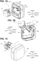
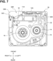
- a printer 1 illustrated in FIGS. 1A, 1B, and 1C includes a printing cassette 10 and a printer body 100.
- the printer 1 is a device that performs printing on a tape-shaped printing medium.
- an axial direction of an output gear 18 is defined as an up-down direction.
- a direction that is perpendicular to the up-down direction and in which the output gear 18 and an input spool 16 are arranged next to each other is defined as a front-rear direction.
- a direction perpendicular to both the up-down direction and the front-rear direction is defined as a left-right direction.
- the printing cassette 10 accommodates a printing medium.
- the printing cassette 10 is mountable on and removable from the printer body 100. Replacing the printing cassette 10 can achieve resupply of a printing medium and change of a type (e.g., color, material, or others) of the printing medium.
- a type e.g., color, material, or others
- the printing cassette 10 includes a case 35 that accommodates a to-be-printed tape (described later) (an example of a first tape), an ink ribbon, and others.
- An outer shape of the printing cassette 10 i.e., a shape of the case 35
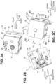
- the case 35 includes a first cover portion 31, a first frame portion 32, a second frame portion 33, and a second cover portion 34.
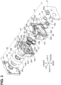
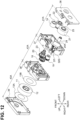
- the printing cassette 10 includes a first roll 11, a first feed spool 12, a spacer film 13A, a spacer film 13B, a second roll 14, a second feed spool 15, an input spool 16, a clutch spring holder 17, the output gear 18, the input gear 19, and an idle gear 20.
- a to-be-printed tape on which printing is to be performed is wound around the first feed spool 12. Printing is performed on a surface of the to-be-printed tape by a print head 102 (described later) of the printer body 100 and an ink ribbon.
- Two spacer films 13A, 13B are disposed outside the first roll 11 in the up-down direction such that the spacer films 13A, 13B sandwich the first roll 11 therebetween.
- the spacer film 13A is disposed between the first roll 11 and the second cover portion 34
- the spacer film 13B is disposed between the first roll 11 and the second frame portion 33.
- the first feed spool 12 is rotatable about its rotation axis.
- the first feed spool 12 rotates along with conveyance of the to-be-printed tape by a platen roller 103 (described later) of the printer body 100, thereby feeding the to-be-printed tape to the print head 102.
- the ink ribbon used for printing on the to-be-printed tape is wound around the second feed spool 15.
- the ink ribbon is laid on the to-be-printed tape and used for printing performed by the print head 102 therein.
- the ink ribbon that has been used for printing is taken up by the input spool 16 (described later).
- a rotation resistance is applied to the second roll 14 by a clutch spring held by the clutch spring holder 17.
- the second feed spool 15 is rotatable about its rotation axis.
- the rotation axis of the second feed spool 15 is parallel to the rotational axis of the first feed spool 12, that is, parallel to the up-down direction.
- the second feed spool 15 rotates along with take-up of the ink ribbon by the input spool 16, thereby feeding the ink ribbon to the print head 102. Further, the second feed spool 15 is disposed such that a portion thereof overlaps the first roll 11 in the up-down direction.
- the input spool 16 is rotatable about its rotation axis.
- the rotation axis of the input spool 16 is parallel to the rotation axis of the second feed spool 15.
- the input spool 16 has a cylindrical shape and has a hollow portion defined by an inner peripheral surface 16A. Spline teeth 16B are provided on the inner peripheral surface 16A of the input spool 16.
- a drive shaft 105 (described later) of the printer body 100 is to be coupled to the spline teeth 16B. The input spool 16 is rotated by the drive shaft 105 to take up the ink ribbon.
- the output gear 18 is a single gear for outputting, to the outside, a driving force for conveying the to-be-printed tape.
- the output gear 18 transmits a driving force to the platen roller 103 via a platen gear 104 of the printer body 100 (described later).
- the output gear 18 includes a disk that rotates about its rotation axis parallel to the up-down direction and teeth on a surface of the disk extending parallel to the up-down direction.
- One (i.e., an upper surface) of surfaces of the disk extending perpendicular to the up-down direction faces a cover portion 33B (described later) of the case 35 in the up-down direction.
- a portion of the other (i.e., a lower surface) of the surfaces of the disk extending perpendicular to the up-down direction does not face the case 35 in the up-down direction.
- the output gear 18 is partially exposed to the head opening 32B, and thus, the exposed portion thereof is located outside the case 35.
- the output gear 18 is in engagement with the platen gear 104 at the head opening 32B in a state where the printing cassette 10 is mounted on the printer body 100.
- the first roll 11, the output gear 18, and the second roll 14 are disposed in the order of the first roll 11, the output gear 18, and the second roll 14 in the up-down direction. That is, the output gear 18 is positioned between the first roll 11 and the second roll 14 in the up-down direction.
- the input gear 19 is indirectly connected to the output gear 18 via an idle gear 20 (described later) and transmits a driving force to the output gear 18.
- a driving force from a driving source of the printer body 100 is input to the input gear 19.
- the input gear 19 includes an external gear 19A and a cylindrical spool 19B fixed to a lower surface of the external gear 19A and having spline teeth on an inner peripheral surface thereof.
- the external gear 19A rotates integrally with the spool 19B by the driving force input to the spool 19B.
- a rotation axis of the input gear 19 (i.e., a rotation axis of the external gear 19A and a rotation axis of the spool 19B) is coaxial with the rotation axis of the input spool 16.
- the input spool 16, the input gear 19, and the first roll 11 are disposed in the order of the input spool 16, the input gear 19, and the first roll 11 in the up-down direction.
- the input gear 19 is positioned between the input spool 16 and the first roll 11 in the up-down direction. Further, the input gear 19 is disposed such that a portion thereof overlaps the first roll 11 in the up-down direction.
- the rotation axis of the input gear 19 extends in the hollow portion of the input spool 16. That is, the drive shaft 105 is inserted into the input spool 16 and the input gear 19 simultaneously. As a result, although the input gear 19 is not directly coupled to the input spool 16, the input gear 19 is rotated by a driving source (i.e., the drive shaft 105) common to the input spool 16.
- a driving source i.e., the drive shaft 105
- the idle gear 20 is connected to be driven to (i.e., is in engagement with) the input gear 19 and the output gear 18, and transmits the driving force input to the input gear 19 to the output gear 18.
- the idle gear 20 is a stepped gear in which a first gear 20A engaged with the input gear 19 and a second gear 20B engaged with the output gear 18 are arranged coaxially.
- the second gear 20B has a diameter smaller than the first gear 20A. Further, the second gear 20B is disposed at a position closer to the first roll 11 than the second gear 20B to the first gear 20A in the up-down direction (i.e., on an upper side).
- the idle gear 20 constitutes a deceleration mechanism that decelerates the driving force input to the input gear 19.
- the first cover portion 31 serves as a lower end portion of the printing cassette 10.
- the first frame portion 32 is disposed above the first cover portion 31 and is connected to the first cover portion 31 in the up-down direction.
- the second frame portion 33 is disposed above the first frame portion 32 and is connected to the first frame portion 32 in the up-down direction.
- the second cover portion 34 serves as an upper end portion of the printing cassette 10.
- the second cover portion 34 is connected to the second frame portion 33 in the up-down direction.
- the first cover portion 31 and a first portion that is a lower side of the first frame portion 32 constitute a first case portion 41 in which the second roll 14 (i.e., at least a portion of the ink ribbon), the second feed spool 15, and the input spool 16 are accommodated. That is, the second roll 14, the second feed spool 15, and the input spool 16 are disposed in a space surrounded by the first cover portion 31 and the first frame portion 32.
- the first case portion 41 is further provided with an outlet 32C through which the to-be-printed tape is discharged.
- a second portion of the first frame portion 32 that is a side (i.e., an upper side) opposite to the first portion in the up-down direction and a third portion that is a lower side of the second frame portion 33 constitute a second case portion 42 in which a particular portion of the output gear 18, the input gear 19, and the idle gear 20 are accommodated. That is, the particular portion of the output gear 18, the input gear 19, and the idle gear 20 are disposed in a space surrounded by the first frame portion 32 and the second frame portion 33.
- a fourth portion of the second frame portion 33 that is a side (i.e., an upper side) opposite to the third portion in the up-down direction and the second cover portion 34 constitute a third case portion 43 in which the first roll 11 (i.e., at least a portion of the to-be-printed tape) is accommodated. That is, the first roll 11 is disposed in a space surrounded by the second frame portion 33 and the second cover portion 34.
- the first case portion 41, the second case portion 42, and the third case portion 43 are disposed in the order of the first case portion 41, the second case portion 42, and the third case portion 43 in the up-down direction. That is, the second case portion 42 is disposed between the first case portion 41 and the third case portion 43 in the up-down direction.
- a dimension of the first case portion 41 in the up-down direction and a dimension of the third case portion 43 in the up-down direction are both greater than a dimension of the second case portion 42 in the up-down direction. Further, the dimension of the first case portion 41 in the up-down direction is greater than or equal to the dimension of the third case portion 43 in the up-down direction. A dimension of the second frame portion 33 in the up-down direction is greater than a dimension of the first frame portion 32 in the up-down direction.
- the first frame portion 32 includes a first sidewall 32A, the head opening 32B, the outlet 32C, a first guide 32D, a protruding portion 32E, a facing portion 32F, a first separation wall 32G, an outlet for opening 32K, a first restricting portion 32L, and a first partition wall 32M.
- the first sidewall 32A defines side surfaces of the printing cassette 10. The side surfaces of the printing cassette 10 extend parallel to the up-down direction.
- the head opening 32B is a cutaway portion of the first sidewall 32A.
- the head opening 32B is a space in which the print head 102 is located by insertion into the head opening 32B from below in a state where the printing cassette 10 is mounted to the printer body 100.
- the head opening 32B opens downward in the printing cassette 10.
- the first guide 32D is a portion around which a to-be-printed tape 11A fed from the third case portion 43 is wound.
- the first guide 32D has a plurality of ribs being plates that are apart from each other in a circumferential direction of the second roll 14.
- the plurality of ribs protrude in a radial direction of the second roll 14, and a protruding amount of each of the plurality of ribs (i.e., a plate width) decreases as each of the plurality of ribs extends downward.
- the protruding portion 32E is located upstream from the head opening 32B in a conveyance direction of the to-be-printed tape, and is a portion in which the to-be-printed tape and the ink ribbon are conveyed parallel to each other.
- the protruding portion 32E extends in the left-right direction.
- the to-be-printed tape and the ink ribbon are conveyed inside the protruding portion 32E from left to right during printing.
- the protruding portion 32E has a first surface 32H that defines the head opening 32B.
- the first surface 32H serves as a rear surface of the protruding portion 32E and is orthogonal to the front-rear direction. In a state where the printing cassette 10 is mounted on the printer body 100, the first surface 32H faces the print head 102 in the front-rear direction.
- the facing portion 32F is a plate portion facing the protruding portion 32E in the front-rear direction.
- the facing portion 32F separates the head opening 32B and a space in which the second roll 14, the second feed spool 15, and the input spool 16 are disposed in the front-rear direction.
- the facing portion 32F defines the head opening 32B and has a second surface 32I (refer to FIG. 3 ) facing the first surface 32H in the front-rear direction.
- the second surface 32I serves as a front surface of the facing portion 32F and is orthogonal to the front-rear direction. In a state where the printing cassette 10 is mounted on the printer body 100, the second surface 32I is opposite to the first surface 32H with respect to the print head 102 in the front-rear direction.
- the first separation wall 32G separates the first case portion 41 and the second case portion 42 in the up-down direction.
- the first separation wall 32G is a portion of the second case portion 42. That is, in the first frame portion 32, the first portion constituting the first case portion 41 is a portion lower than the first separation wall 32G.
- the protruding portion 32E and the facing portion 32F protrude downward from the first separation wall 32G.
- the protruding portion 32E and the facing portion 32F are portions of the first case portion 41.
- the first separation wall 32G has a third surface 32J that is disposed at an upper end of the head opening 32B in the up-down direction and connects between the protruding portion 32E and the facing portion 32F.
- the third surface 32J serves as a lower surface of the first separation wall 32G and is orthogonal to the up-down direction.
- the outlet for opening 32K is a portion through which the to-be-printed tape that travels in the protruding portion 32E is to be discharged to the head opening 32B.
- the outlet for opening 32K is provided at a right end of the protruding portion 32E.
- the ink ribbon drawn from the second roll 14 is laid on the to-be-printed tape discharged from the outlet for opening 32K to the head opening 32B.
- the first restricting portion 32L restricts movement of the to-be-printed tape in a width direction of the to-be-printed tape.
- the first restricting portion 32L is disposed between both ends (i.e., an upper end and a lower end) of the outlet 32C in the width direction of the to-be-printed tape (i.e., the up-down direction) in the first case portion 41 (refer to FIG. 8B ).
- the first restricting portion 32L protrudes further upward from a support portion 32N protruding leftward from the first sidewall 32A at a right rear portion of the first frame portion 32.
- the first partition wall 32M separates a space in which the output gear 18, the input gear 19, and the idle gear 20 are disposed and a space through which the to-be-printed tape travels. Specifically, in the second frame portion 33, the first partition wall 32M separates an inner area where the output gear 18, the input gear 19, and the idle gear 20 are disposed and an outer area that is more outside than the inner area.
- the second frame portion 33 includes a second sidewall 33A, a cover portion 33B, a second guide 33C, a first gear support portion 33D, a second gear support portion 33E, a third gear support portion 33F, a second partition wall 33G, a second separation wall 33H, a first claw 331, a second claw 33J, a third claw 33K, a fourth claw 33L, and a second restricting portion 33M (refer to FIG. 8B ).
- the second sidewall 33A defines side surfaces of the printing cassette 10. The side surfaces of the printing cassette 10 extend parallel to the up-down direction.
- the cover portion 33B has surfaces perpendicular to the up-down direction.
- the cover portion 33B is disposed at a position where the cover portion 33B overlaps the output gear 18 in the up-down direction.
- the cover portion 33B is contiguous with a lower end portion of the second sidewall 33A, and is disposed at a right front corner of the second frame portion 33.
- the output gear 18, the cover portion 33B, and the first roll 11 are arranged next to each other in the order of the output gear 18, the cover portion 33B, and the first roll 11 in the up-down direction. As described above, an upper surface of the output gear 18 is entirely covered by the cover portion 33B.
- the second guide 33C is a portion around which the to-be-printed tape 11A drawn from the first roll 11 is wound.
- the second guide 33C has a plurality of ribs being plates that are apart from each other in a circumferential direction of the first roll 11.
- the plurality of ribs protrude in a radial direction of the first roll 11, and a protruding amount of each of the plurality of ribs (i.e., a plate width) increases as each of the plurality of ribs extends downward.
- the first gear support portion 33D illustrated in FIG. 5C supports the output gear 18 rotatably.
- the second gear support portion 33E supports the input gear 19 rotatably.
- the third gear support portion 33F supports the idle gear 20 rotatably.
- the second partition wall 33G separates a space in which the output gear 18, the input gear 19, and the idle gear 20 are disposed and a space through which the to-be-printed tape travels. Specifically, in the second frame portion 33, the second partition wall 33G separates an inner area where the first gear support portion 33D, the second gear support portion 33E, and the third gear support portion 33F are disposed and an outer area in which the second guide 33C is disposed. The second guide 33C protrudes from the second partition wall 33G.
- the second separation wall 33H separates the second case portion 42 and the third case portion 43 in the up-down direction.
- the second separation wall 33H is a portion of the third case portion 43. That is, in the second frame portion 33, the third portion constituting the second case portion 42 is a portion lower than the second separation wall 33H.
- first gear support portion 33D, the second gear support portion 33E, the third gear support portion 33F, and the second partition wall 33G protrude downward from the second separation wall 33H. Therefore, the first gear support portion 33D, the second gear support portion 33E, the third gear support portion 33F, and the second partition wall 33G are portions of the second case portion 42.
- the first claw 331 is disposed at a front end portion of the second frame portion 33.
- the second claw 33J is disposed at a left end portion of the second frame portion 33.
- the third claw 33K is disposed at a rear end portion of the second frame portion 33.
- the fourth claw 33L is disposed at a right end portion of the second frame portion 33.
- Each of the claws 331, 33J, 33K, and 33L protrudes downward and engages a corresponding opening or groove defined in the first sidewall 32A of the first frame portion 32. That is, the claws 33I, 33J, 33K, 33L connect between the first frame portion 32 and the second frame portion 33 in the up-down direction.
- the output gear 18, the input gear 19, and the idle gear 20 are disposed between the first claw 33I and the third claw 33K in the front-rear direction and between the second claw 33J and the fourth claw 33L in the right-left direction.
- the second restricting portion 33M restricts movement of the to-be-printed tape in the width direction of the to-be-printed tape.
- the second restricting portion 33M protrudes rightward from the second sidewall 33A at a left rear portion of the second frame portion 33.
- the second cover portion 34 illustrated in FIG. 3 has a third restricting portion 34A that restricts movement of the to-be-printed tape in the width direction.
- the third restricting portion 34A is disposed between both ends (i.e., an upper end and a lower end) of the first roll 11 in the width direction of the to-be-printed tape (i.e., the up-down direction) in the third case portion 43 (refer to FIG. 8B ).
- the third restricting portion 34A is a plate member disposed at a right rear portion of the second cover portion 34 such that a thickness direction of the third restricting portion 34A is parallel to the right-left direction.
- a volume of an internal space of the third case portion 43 is greater than a volume of an internal space of the first case portion 41.
- a total weight of the third case portion 43 and the components (i.e., the first roll 11, the first feed spool 12, and others) accommodated in the third case portion 43 is greater than a total weight of the first case portion 41 and the components (i.e., the second roll 14, the second feed spool 15, the input spool 16, and others) accommodated in the first case portion 41.
- the to-be-printed tape 11A and the ink ribbon 14A extend across the head opening 32B in the right-left direction.
- the to-be-printed tape 11A on which printing has been performed is discharged to the outside of the printer 1 from the outlet 32C.
- the output gear 18 is located inside an outer edge of the case 35.
- the entire output gear 18 overlaps the case 35 in the up-down direction.
- the first guide 32D and the second guide 33C define a path through which the to-be-printed tape 11A constituting the first roll 11 is fed from the third case portion 43 to the first case portion 41.
- the to-be-printed tape 11A drawn from the first roll 11 is conveyed in a spiral manner toward the lower rear in the third case portion 43 while contacting the second guide 33C from an outer side in the radial direction of the first roll 11.
- the to-be-printed tape 11A is further conveyed toward the lower left while extending across the second case portion 42 in the up-down direction.
- the to-be-printed tape 11A that has passed the second case portion 42 and reached the first case portion 41 is conveyed toward the lower front with contacting the first guide 32D from the outer side in the radial direction.
- the to-be-printed tape 11A that has passed the first case portion 41 and reached the lower end portion of the printing cassette 10 passes the head opening 32B and is then discharged from the outlet 32C.
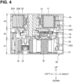
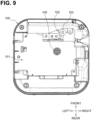
- the printer body 100 includes a cassette insertion portion 101, the print head 102, the platen roller 103, the platen gear 104, and the drive shaft 105.
- the cassette insertion portion 101 is a recessed portion on which the printing cassette 10 is to be mounted.
- the cassette insertion portion 101 has a function of positioning the printing cassette 10.
- the print head 102 is a device for performing printing on the to-be-printed tape held by the printing cassette 10.
- the print head 102 is disposed in the cassette insertion portion 101.
- the print head 102 is disposed such that, in a state where the printing cassette 10 is mounted on the printer body 100, the print head 102 overlaps the to-be-printed tape and the ink ribbon in the front-rear direction at the head opening 32B.
- the print head 102 has a plurality of heating elements, heat generation of which are individually controlled.
- the to-be-printed tape that has been conveyed to the head opening 32B by the platen roller 103 (described later) is pressed toward the print head 102 in which the heating elements have generated heat, via the ink ribbon.
- some ink on a particular surface of the ink ribbon is transferred onto the to-be-printed tape, and characters, symbols, and other representations are printed on the to-be-printed tape.
- the platen roller 103 is a roller for conveying the to-be-printed tape from the inside to the outside of the printing cassette 10.
- a rotation axis of the platen roller 103 is parallel to the up-down direction.
- the platen roller 103 is disposed adjacent to the print head 102 in the cassette insertion portion 101.
- the platen roller 103 contacts and presses the to-be-printed tape toward the print head 102 at the head opening 32B.
- the platen gear 104 is a driving force transmission portion that is connected to be driven to the platen roller 103 and is to be engaged with the output gear 18.
- a rotation axis of the platen gear 104 is coaxial with the rotation axis of the platen roller 103.
- the platen roller 103 and the platen gear 104 are swingable between a position illustrated in FIG. 9 where the platen roller 103 and the platen gear 104 are spaced from the printing cassette 10 and a position illustrated in FIG. 10 where the platen gear 104 is in engagement with the output gear 18.
- the drive shaft 105 is a shaft that is engaged with the input gear 19 when the drive shaft 105 is inserted into the input spool 16, and that rotates the input spool 16 and the input gear 19.
- the drive shaft 105 is disposed in the cassette insertion portion 101.
- a rotation axis of the drive shaft 105 is parallel to the up-down direction.
- the drive shaft 105 rotates about its rotation axis by a driving source (e.g., a motor) (not illustrated).
- the drive shaft 105 is in engagement with the input gear 19 and the platen gear 104 is in engagement with the output gear 18. Specifically, the drive shaft 105 is inserted into the input spool 16 and the input gear 19 of the printing cassette 10, and the platen roller 103 and the platen gear 104 are swung toward the head opening 32B of the printing cassette 10, whereby the printing cassette 10 is mounted on the printer body 100.
- the output gear 18 is disposed at the second case portion 42 sandwiched between the first case portion 41 and the third case portion 43. Therefore, even if the printing cassette 10 is dropped and the surface of the printing cassette 10 extending perpendicular to the axial direction of the rotation axis of the output gear 18 collides with a surface of a floor or somewhere, the output gear 18 is protected by the first case portion 41 and the third case portion 43 and damage to the output gear 18 is reduced.
- the protruding portion 32E and the facing portion 32F are connected to each other by the third surface 32J.
- strength of the protruding portion 32E can be increased.
- damage to the protruding portion 32E when the printing cassette 10 is dropped is reduced.
- the volume and total weight of the third case portion 43 is greater than the volume and total weight of the first case portion 41.
- the third case portion 43 faces down and is likely to collides with a surface of a floor surface or somewhere. Therefore, damage to the output gear 18 disposed at the first case portion 41 and exposed to the head opening 32B is reduced.
- the to-be-printed tape wound around the first feed spool 12 can be smoothly fed from the third case portion 43 to the first case portion 41 by the first restricting portion 32L, the second restricting portion 33M, and the third restricting portion 34A.
- the first partition wall 32M and the second partition wall 33G prevent the to-be-printed tape conveyed toward the outlet 32C from interfering with the output gear 18, the input gear 19, and the idle gear 20.
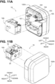
- a printer 1A illustrated in FIGS. 11A and 11B includes a printing cassette 10A and a printer body 100A.
- the printing cassette 10A includes a third roll 21, an additional spool 22, an additional gear 23, and a pinch roller 24, each of which are illustrated in FIG. 11 , in addition to the components of the printing cassette 10 of the first embodiment, and further includes a third feed spool 25, a first cover portion 36, a first frame portion 37, a second frame portion 38, and a second cover portion 39 as alternatives to the input spool 16, the first cover portion 31, the first frame portion 32, the second frame portion 33, and the second cover portion 34 of the printing cassette 10 of the first embodiment.
- the first cover portion 36 and the first frame portion 37 constitute a first case portion 41A.
- the first frame portion 37 and the second frame portion 38 constitute a second case portion 42A.
- the second frame portion 38 and the second cover portion 39 constitute a third case portion 43A.
- the third feed spool 25 is identical to the input spool 16 except that the third feed spool 25 does not have the spline teeth 16B.
- the first cover portion 36, the first frame portion 37, the second frame portion 38, and the second cover portion 39 are identical to the first cover portion 31, the first frame portion 32, the second frame portion 33, and the second cover portion 34 that are further extended in the right-left direction, respectively.
- the other configurations of the printing cassette 10A are the same as those of the printing cassette 10 of the first embodiment except for the points described below, and thus a description thereof will be omitted.
- a laminating tape used for protecting the to-be-printed tape is wound around the third feed spool 25.
- the laminating tape has an adhesive surface to be adhered to the to-be-printed tape on which printing has been performed by the print head 102.
- the additional spool 22 is rotatable about its rotation axis.
- the rotation axis of the additional spool 22 is parallel to the rotation axis of the second feed spool 15 (i.e., the up-down direction).
- the additional spool 22 is a take-up spool that takes up the ink ribbon by rotation of the additional gear 23 (described later).
- the additional gear 23 is connected to the additional spool 22 and is in engagement with the idle gear 20.
- the additional gear 23 is rotated by a driving force input to the input gear 19 and rotates the additional spool 22.
- the pinch roller 24 lays the laminating tape over the to-be-printed tape and presses the laminating tape toward the to-be-printed tape on which printing has been performed, in cooperation with a pressing roller 106 (described later).
- the pinch roller 24 is disposed downstream from the head opening 32B in the conveyance direction of the to-be-printed tape.
- At least a portion (i.e., a portion drawn from the first roll 11) of the to-be-printed tape, at least a portion of the laminating tape, and at least a portion of the pinch roller 24 are arranged next to each other in directions (i.e., the front-rear direction and the left-right direction) perpendicular to the up-down direction and accommodated in the first case portion 41A.
- the pinch roller 24 is supported by the second case portion 42A such that at least a portion of the pinch roller 24 overlaps the second case portion 42A in directions (i.e., the front-rear direction and the left-right direction) perpendicular to the up-down direction.
- an upper end portion of a shaft portion 24A of the pinch roller 24 is inserted in a recessed portion 371 defined in the first separation wall 32G of the first frame portion 37.
- the recessed portion 371 is a portion of the second case portion 42A.
- the printer body 100A is identical to the printer body 100 of the first embodiment to which the pressing roller 106 illustrated in FIG. 12 is added.
- the other configurations of the printer body 100A are the same as those of the printer body 100 of the first embodiment except for the points described below, and thus a description thereof will be omitted.
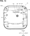
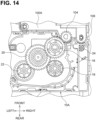
- the pressing roller 106 is configured to be swingable together with the platen roller 103 and the platen gear 104. That is, the pressing roller 106 are swingable between a position illustrated in FIG. 13 where the pressing roller 106 is spaced from the printing cassette 10A and a position illustrated in FIG. 14 where the pressing roller 106 presses the to-be-printed tape and the laminating tape in cooperation with the pinch roller 24.
- the printers of the above-described embodiments are not limited to printers that perform printing using an ink ribbon.
- the printers may perform printing using a heat-sensitive sheet that is a continuous strip as a to-be-printed tape.
- a printing cassette might not necessarily include a roll of an ink ribbon and a second feed spool.
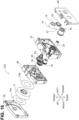
- a printing cassette 10B illustrated in FIG. 15 is identical to the printing cassette 10 of the first embodiment including a roll 51 of a heat-sensitive sheet and a third roll 52 of a laminating tape as alternatives to the first roll 11 and the second roll 14, respectively.
- the third roll 52 is wound around the third feed spool 25 of the second embodiment.
- the printing cassette 10B includes the pinch roller 24 of the second embodiment, but does not include the second feed spool 15.
- first case portion, the second case portion, and the third case portion may include parts other than the first cover portion, the first frame portion, the second frame portion, and the second cover portion described above.
- a laminating tape may be wound around the additional spool.
- a printing cassette 10C illustrated in FIG. 16 is identical to the printing cassette 10A of the second embodiment in which a third roll 21 of a laminating tape is wound around the additional spool 22.
- the printing cassette 10C includes the input spool 16 of the first embodiment as an alternative to the third feed spool 25 of the second embodiment.
- the input spool 16 is used as a take-up spool for an ink ribbon.
Landscapes
- Impression-Transfer Materials And Handling Thereof (AREA)
- Printers Characterized By Their Purpose (AREA)
- Handling Of Continuous Sheets Of Paper (AREA)
- Replacement Of Web Rolls (AREA)
Applications Claiming Priority (3)
| Application Number | Priority Date | Filing Date | Title |
|---|---|---|---|
| JP2019178164A JP7395912B2 (ja) | 2019-09-30 | 2019-09-30 | 印刷用カセット及び印刷装置 |
| PCT/JP2020/034876 WO2021065476A1 (ja) | 2019-09-30 | 2020-09-15 | 印刷用カセット及び印刷装置 |
| EP20872840.2A EP4039482B1 (de) | 2019-09-30 | 2020-09-15 | Druckkassette und drucker |
Related Parent Applications (2)
| Application Number | Title | Priority Date | Filing Date |
|---|---|---|---|
| EP20872840.2A Division EP4039482B1 (de) | 2019-09-30 | 2020-09-15 | Druckkassette und drucker |
| EP20872840.2A Division-Into EP4039482B1 (de) | 2019-09-30 | 2020-09-15 | Druckkassette und drucker |
Publications (2)
| Publication Number | Publication Date |
|---|---|
| EP4501651A2 true EP4501651A2 (de) | 2025-02-05 |
| EP4501651A3 EP4501651A3 (de) | 2025-03-12 |
Family
ID=75272237
Family Applications (2)
| Application Number | Title | Priority Date | Filing Date |
|---|---|---|---|
| EP24219495.9A Pending EP4501651A3 (de) | 2019-09-30 | 2020-09-15 | Druckkassette und drucker |
| EP20872840.2A Active EP4039482B1 (de) | 2019-09-30 | 2020-09-15 | Druckkassette und drucker |
Family Applications After (1)
| Application Number | Title | Priority Date | Filing Date |
|---|---|---|---|
| EP20872840.2A Active EP4039482B1 (de) | 2019-09-30 | 2020-09-15 | Druckkassette und drucker |
Country Status (12)
| Country | Link |
|---|---|
| US (3) | US11951753B2 (de) |
| EP (2) | EP4501651A3 (de) |
| JP (3) | JP7395912B2 (de) |
| KR (1) | KR102869393B1 (de) |
| CN (3) | CN119116564A (de) |
| AU (2) | AU2020359501B2 (de) |
| CA (1) | CA3155832A1 (de) |
| ES (1) | ES3007483T3 (de) |
| MX (2) | MX2022003659A (de) |
| PH (1) | PH12022550735A1 (de) |
| PL (1) | PL4039482T3 (de) |
| WO (1) | WO2021065476A1 (de) |
Families Citing this family (2)
| Publication number | Priority date | Publication date | Assignee | Title |
|---|---|---|---|---|
| JP7395912B2 (ja) * | 2019-09-30 | 2023-12-12 | ブラザー工業株式会社 | 印刷用カセット及び印刷装置 |
| USD989170S1 (en) * | 2020-12-17 | 2023-06-13 | Liling Bao | Label printer cassette |
Citations (1)
| Publication number | Priority date | Publication date | Assignee | Title |
|---|---|---|---|---|
| JP2010234772A (ja) | 2009-03-31 | 2010-10-21 | Brother Ind Ltd | テープカセットおよびテープ印字装置 |
Family Cites Families (99)
| Publication number | Priority date | Publication date | Assignee | Title |
|---|---|---|---|---|
| JPS5036734B1 (de) | 1970-04-13 | 1975-11-27 | ||
| SE364584B (de) | 1970-04-13 | 1974-02-25 | Canon Kk | |
| US3672603A (en) | 1970-06-26 | 1972-06-27 | Cartridge Television Inc | Tape cartridge |
| US3804227A (en) | 1972-05-03 | 1974-04-16 | Scm Corp | Typewriter ribbon cartridge |
| US3948382A (en) | 1973-01-29 | 1976-04-06 | The Singer Company | Data terminal printing assembly |
| US4034935A (en) | 1975-11-19 | 1977-07-12 | Xerox Corporation | Dual level ribbon cartridge |
| CA1119549A (en) | 1978-01-30 | 1982-03-09 | Collier M. Miller | Ribbon cartridge drive |
| US4252450A (en) | 1978-10-03 | 1981-02-24 | Xerox Corporation | Ribbon drive with spring-loaded idler |
| US4397574A (en) | 1979-10-29 | 1983-08-09 | Ncr Corporation | Reloadable ribbon cassette |
| GB2064476B (en) | 1979-11-29 | 1983-08-10 | Itt Creed | Ink ribbon cassette |
| NL8200181A (nl) | 1981-01-31 | 1982-08-16 | Victor Company Of Japan | Registreer- en /of reproduceerinrichting. |
| US4402619A (en) | 1981-03-30 | 1983-09-06 | Kroy, Inc. | Printing apparatus and printing cartridge therefor |
| JPS58122887A (ja) | 1982-01-18 | 1983-07-21 | Silver Seiko Ltd | タイプライタ−のモ−タ駆動装置 |
| JPS58141479A (ja) | 1982-02-15 | 1983-08-22 | Canon Inc | カセツト |
| JPS58175949U (ja) | 1982-05-20 | 1983-11-25 | 大和製衡株式会社 | ラベルプリンタ |
| FR2528929B1 (fr) | 1982-06-17 | 1988-04-08 | Sagem | Perfectionnements apportes a des dispositifs mecaniques d'entrainement selectif d'au moins deux arbres menes a partir d'un arbre menant unique, notamment pour le deplacement longitudinal d'un ruban encreur dans une machine imprimante |
| JPS5995180A (ja) | 1982-11-22 | 1984-06-01 | Matsushita Electric Ind Co Ltd | インクリボンカセツト |
| US4490059A (en) | 1983-05-04 | 1984-12-25 | Wordex | Ribbon metering device |
| US4856921A (en) | 1983-06-28 | 1989-08-15 | Alps Electric Co., Ltd. | Rotary wheel printer |
| JPS608072U (ja) | 1983-06-30 | 1985-01-21 | アルプス電気株式会社 | プリンタ |
| JPS609657U (ja) | 1983-07-01 | 1985-01-23 | アルプス電気株式会社 | プリンタ |
| DE3424045A1 (de) | 1983-06-30 | 1985-01-03 | Alps Electric Co., Ltd., Tokio/Tokyo | Typenraddrucker |
| JPS6036255U (ja) | 1983-08-22 | 1985-03-13 | 日本電産コパル株式会社 | 熱転写式シリアルプリンタ− |
| JPS6046254U (ja) | 1983-09-06 | 1985-04-01 | アルプス電気株式会社 | リボンカセツト |
| JPS6048456U (ja) | 1983-09-12 | 1985-04-05 | 株式会社東芝 | 熱転写形プリンタ |
| JPH0227613B2 (ja) | 1984-03-08 | 1990-06-19 | Teraoka Seiko Kk | Denshihakaryopurinta |
| US4598780A (en) | 1984-03-02 | 1986-07-08 | Teraoka Seiko Co., Ltd. | Electronic scale printer |
| US4668961A (en) | 1984-04-20 | 1987-05-26 | Canon Kabushiki Kaisha | Recording apparatus |
| JPS60224571A (ja) | 1984-04-20 | 1985-11-08 | Canon Inc | 転写記録装置 |
| JPS6127277A (ja) * | 1984-07-19 | 1986-02-06 | Tokyo Electric Co Ltd | 印字機のリボンカセツト |
| JPS61154877A (ja) | 1984-12-27 | 1986-07-14 | Matsushita Electric Ind Co Ltd | リボンカセツト |
| JPH0761729B2 (ja) | 1985-10-30 | 1995-07-05 | 株式会社リコー | 印字装置のリボンカセツト |
| JPS63156762U (de) | 1987-04-02 | 1988-10-14 | ||
| US4832514A (en) | 1988-02-01 | 1989-05-23 | Kroy Inc. | Thermal transfer device and tape-ribbon cartridge therefor |
| JPH029562U (de) | 1988-06-22 | 1990-01-22 | ||
| JPH026173A (ja) | 1988-06-27 | 1990-01-10 | Canon Inc | リボン送り装置 |
| JPH0211379A (ja) | 1988-06-30 | 1990-01-16 | Canon Inc | インクリボンカセット |
| JPH0211380A (ja) | 1988-06-30 | 1990-01-16 | Canon Inc | インクリボンカセット |
| JPH0319744A (ja) * | 1989-06-15 | 1991-01-28 | Daido Steel Co Ltd | 切削加工装置 |
| US5099378A (en) | 1989-08-24 | 1992-03-24 | Minnesota Mining And Manufacturing Company | Carrier with external interlock for videocassette |
| IT218846Z2 (it) | 1989-11-16 | 1992-11-05 | Incas Holding Spa | Notarbartolo & gervasi |
| US5234179A (en) | 1990-02-20 | 1993-08-10 | Minnesota Mining And Manufacturing Company | Videotape adaptor for use with a cartridge |
| JPH03284973A (ja) | 1990-04-02 | 1991-12-16 | Canon Inc | リボンカセット及び前記リボンカセットを用いる記録装置 |
| JPH04152176A (ja) | 1990-10-16 | 1992-05-26 | Nec Corp | プリンタのインクリボンカセット |
| JPH0553956A (ja) | 1991-08-29 | 1993-03-05 | Mitsubishi Electric Corp | コンピユータ通信網構成支援システム |
| JPH0541834U (ja) | 1991-11-11 | 1993-06-08 | フジコピアン株式会社 | インクリボンカセツト |
| JPH0553956U (ja) | 1991-12-24 | 1993-07-20 | 日本電気ホームエレクトロニクス株式会社 | インクリボンカセット |
| US5325114A (en) | 1992-09-24 | 1994-06-28 | Pitney Bowes Inc. | Thermal printing postage meter system |
| JP3341052B2 (ja) | 1993-06-28 | 2002-11-05 | カシオ計算機株式会社 | 印刷用カセット |
| JP2831237B2 (ja) | 1993-07-19 | 1998-12-02 | 富士通アイソテック株式会社 | インクリボンカセット |
| US5435657A (en) | 1993-12-28 | 1995-07-25 | Smith Corona Corporation | Label printer and tape and ink ribbon cartridge for use therein |
| JPH07276755A (ja) | 1994-04-06 | 1995-10-24 | Casio Comput Co Ltd | 印刷用カセットおよび印刷装置 |
| JPH07276757A (ja) | 1994-04-11 | 1995-10-24 | Fujicopian Co Ltd | 転写リボンカセット |
| US5619244A (en) | 1994-12-27 | 1997-04-08 | Pitney Bowes Inc. | Thermal ink cassette for a thermal printing device |
| JP3160173B2 (ja) | 1994-12-28 | 2001-04-23 | アルプス電気株式会社 | テープ印字装置 |
| JP3113532B2 (ja) | 1994-12-28 | 2000-12-04 | アルプス電気株式会社 | テープカセット |
| JPH08183230A (ja) * | 1994-12-29 | 1996-07-16 | Casio Comput Co Ltd | 印刷用カセットおよび印刷装置 |
| US5917532A (en) | 1996-11-29 | 1999-06-29 | Pitney Bowes Inc. | Thermal ink ribbon cassette for mailing machines |
| US5959652A (en) | 1997-07-11 | 1999-09-28 | Pitney Bowes Inc. | Thermal ink ribbon cassette for mailing machines |
| EP0891871B1 (de) | 1997-07-15 | 2004-03-03 | Alps Electric Co., Ltd. | Druckkassette |
| JP3549370B2 (ja) * | 1997-07-15 | 2004-08-04 | アルプス電気株式会社 | カートリッジおよびこのカートリッジを用いた記録装置 |
| JP2000052628A (ja) * | 1998-08-04 | 2000-02-22 | Fujicopian Co Ltd | インクリボンカセット |
| JP4174873B2 (ja) | 1998-09-29 | 2008-11-05 | ブラザー工業株式会社 | テープカセット |
| FR2796372B1 (fr) | 1999-07-13 | 2001-09-07 | Dassault Automatismes | Cassette a ruban consommable, notamment pour dispositif de traitement de titres de transport |
| JP2001047713A (ja) | 1999-08-05 | 2001-02-20 | Fujicopian Co Ltd | インクリボンカセット |
| JP4574869B2 (ja) | 2001-01-18 | 2010-11-04 | 日本電産コパル株式会社 | サーマルプリンタ |
| GB0230196D0 (en) | 2002-12-24 | 2003-02-05 | Esselte Nv | Identifying compatible combination for a thermal printer |
| EP1575782B1 (de) | 2002-12-24 | 2015-07-01 | Dymo | Druckgerät und kassette |
| GB0230200D0 (en) | 2002-12-24 | 2003-02-05 | Esselte Nv | Validation of consumables |
| GB0230199D0 (en) * | 2002-12-24 | 2003-02-05 | Esselte Nv | Information on consumables |
| US7070347B2 (en) | 2003-08-12 | 2006-07-04 | Brady Worldwide, Inc. | Printer with a pivoting gear mechanism |
| JP4379178B2 (ja) * | 2004-03-29 | 2009-12-09 | ブラザー工業株式会社 | テープカセット |
| US7484902B2 (en) | 2006-01-24 | 2009-02-03 | Cartec International, Inc. | Ribbon cassette for mailing machine |
| US20080084494A1 (en) | 2006-03-23 | 2008-04-10 | Cartec International, Inc. | Ribbon cassette for mailing machine |
| US7586509B2 (en) | 2007-03-01 | 2009-09-08 | Kabushiki Kaisha Sato | Thermal transfer printer ribbon cassette apparatus and ribbon cassette mounting method |
| JP2008213880A (ja) * | 2007-03-02 | 2008-09-18 | Hitachi Maxell Ltd | テープカートリッジ用の収納ケース |
| JP4337902B2 (ja) | 2007-04-11 | 2009-09-30 | コニカミノルタビジネステクノロジーズ株式会社 | トナー収容容器及びそれに適した画像形成装置 |
| US8465220B2 (en) * | 2007-12-07 | 2013-06-18 | Dymo, N.V. | Label printing apparatus |
| JP5082916B2 (ja) | 2008-02-25 | 2012-11-28 | セイコーエプソン株式会社 | 収容体及び記録装置 |
| US8562228B2 (en) | 2008-12-25 | 2013-10-22 | Brother Kogyo Kabushiki Kaisha | Tape printer |
| AU2009332345B2 (en) | 2008-12-25 | 2014-08-14 | Brother Kogyo Kabushiki Kaisha | Tape cassette and tape printer |
| CN104589815B (zh) | 2009-03-31 | 2017-04-12 | 兄弟工业株式会社 | 带盒和带式打印机 |
| EP3871890B1 (de) | 2009-03-31 | 2024-09-04 | Brother Kogyo Kabushiki Kaisha | Streifenkassette und streifendrucker |
| EP2415610B1 (de) | 2009-03-31 | 2019-07-03 | Brother Kogyo Kabushiki Kaisha | Bandkassette |
| CA2755885C (en) | 2009-03-31 | 2016-10-11 | Brother Kogyo Kabushiki Kaisha | Tape cassette and tape printer |
| JP5482215B2 (ja) | 2010-01-19 | 2014-05-07 | コニカミノルタ株式会社 | 画像形成装置 |
| JP2011148167A (ja) | 2010-01-20 | 2011-08-04 | Oki Data Corp | インクリボンカートリッジ |
| CN102092201B (zh) | 2011-01-10 | 2012-03-07 | 珠海天威飞马打印耗材有限公司 | 色带盒 |
| JP5793339B2 (ja) | 2011-05-11 | 2015-10-14 | フジコピアン株式会社 | 印字装置のインクリボンカセット |
| JP5316658B2 (ja) * | 2012-02-03 | 2013-10-16 | ブラザー工業株式会社 | テープカセット |
| JP5234200B2 (ja) | 2012-03-12 | 2013-07-10 | ブラザー工業株式会社 | テープカセットおよびテープ印字装置 |
| JP6160126B2 (ja) | 2013-03-04 | 2017-07-12 | ブラザー工業株式会社 | 現像カートリッジ |
| CN103273748B (zh) | 2013-06-07 | 2015-09-30 | 红石电脑(上海)有限公司 | 色带匣 |
| JP6144221B2 (ja) | 2014-03-24 | 2017-06-07 | セイコーエプソン株式会社 | テープカートリッジ |
| CN205890264U (zh) * | 2015-07-13 | 2017-01-18 | 兄弟工业株式会社 | 色带盒 |
| JP6398932B2 (ja) * | 2015-09-28 | 2018-10-03 | ブラザー工業株式会社 | リボンカセット |
| JP6354766B2 (ja) * | 2016-01-20 | 2018-07-11 | ブラザー工業株式会社 | 印刷装置 |
| JP6524948B2 (ja) * | 2016-03-29 | 2019-06-05 | ブラザー工業株式会社 | 印字テープ及び印字カセット |
| JP7395912B2 (ja) * | 2019-09-30 | 2023-12-12 | ブラザー工業株式会社 | 印刷用カセット及び印刷装置 |
-
2019
- 2019-09-30 JP JP2019178164A patent/JP7395912B2/ja active Active
-
2020
- 2020-09-15 AU AU2020359501A patent/AU2020359501B2/en active Active
- 2020-09-15 WO PCT/JP2020/034876 patent/WO2021065476A1/ja not_active Ceased
- 2020-09-15 PH PH1/2022/550735A patent/PH12022550735A1/en unknown
- 2020-09-15 ES ES20872840T patent/ES3007483T3/es active Active
- 2020-09-15 CN CN202411323391.0A patent/CN119116564A/zh active Pending
- 2020-09-15 EP EP24219495.9A patent/EP4501651A3/de active Pending
- 2020-09-15 KR KR1020227009688A patent/KR102869393B1/ko active Active
- 2020-09-15 EP EP20872840.2A patent/EP4039482B1/de active Active
- 2020-09-15 CA CA3155832A patent/CA3155832A1/en active Pending
- 2020-09-15 CN CN202411323405.9A patent/CN119189518A/zh active Pending
- 2020-09-15 MX MX2022003659A patent/MX2022003659A/es unknown
- 2020-09-15 CN CN202080066740.9A patent/CN114521176B/zh active Active
- 2020-09-15 PL PL20872840.2T patent/PL4039482T3/pl unknown
-
2022
- 2022-03-23 US US17/702,725 patent/US11951753B2/en active Active
- 2022-03-25 MX MX2025008216A patent/MX2025008216A/es unknown
-
2023
- 2023-11-24 JP JP2023199237A patent/JP7626188B2/ja active Active
-
2024
- 2024-03-07 US US18/599,056 patent/US12296603B2/en active Active
-
2025
- 2025-01-22 JP JP2025009172A patent/JP2025061592A/ja active Pending
- 2025-04-14 US US19/178,838 patent/US20250242602A1/en active Pending
- 2025-10-03 AU AU2025242210A patent/AU2025242210A1/en active Pending
Patent Citations (1)
| Publication number | Priority date | Publication date | Assignee | Title |
|---|---|---|---|---|
| JP2010234772A (ja) | 2009-03-31 | 2010-10-21 | Brother Ind Ltd | テープカセットおよびテープ印字装置 |
Also Published As
| Publication number | Publication date |
|---|---|
| JP2025061592A (ja) | 2025-04-10 |
| CN119189518A (zh) | 2024-12-27 |
| KR102869393B1 (ko) | 2025-10-14 |
| AU2020359501A1 (en) | 2022-04-14 |
| ES3007483T3 (en) | 2025-03-20 |
| JP7626188B2 (ja) | 2025-02-04 |
| CN114521176B (zh) | 2024-10-15 |
| MX2022003659A (es) | 2022-04-25 |
| EP4039482A4 (de) | 2023-10-18 |
| JP2021053876A (ja) | 2021-04-08 |
| EP4039482B1 (de) | 2025-01-22 |
| CN114521176A (zh) | 2022-05-20 |
| US20220212480A1 (en) | 2022-07-07 |
| PL4039482T3 (pl) | 2025-06-23 |
| KR20220066072A (ko) | 2022-05-23 |
| CN119116564A (zh) | 2024-12-13 |
| AU2020359501B2 (en) | 2025-07-17 |
| US12296603B2 (en) | 2025-05-13 |
| EP4501651A3 (de) | 2025-03-12 |
| CA3155832A1 (en) | 2021-04-08 |
| MX2025008216A (es) | 2025-08-01 |
| EP4039482A1 (de) | 2022-08-10 |
| PH12022550735A1 (en) | 2024-05-20 |
| AU2025242210A1 (en) | 2025-10-23 |
| US11951753B2 (en) | 2024-04-09 |
| WO2021065476A1 (ja) | 2021-04-08 |
| EP4039482C0 (de) | 2025-01-22 |
| US20240208241A1 (en) | 2024-06-27 |
| US20250242602A1 (en) | 2025-07-31 |
| JP2024015047A (ja) | 2024-02-01 |
| JP7395912B2 (ja) | 2023-12-12 |
Similar Documents
| Publication | Publication Date | Title |
|---|---|---|
| US20250242602A1 (en) | Printing cassette and printer | |
| EP4023452B1 (de) | Druckvorrichtung und druckkassette | |
| US20250332851A1 (en) | Printer and printing cassette | |
| US20220194106A1 (en) | Printing device, and printing cassette including case that houses input part, output part, and transmission mechanism for transmitting drive force from input part to output part | |
| US20250340077A1 (en) | Print cassette | |
| EP3950365B1 (de) | Kassette | |
| US11813879B2 (en) | Printer | |
| RU2808609C1 (ru) | Печатающая кассета и принтер |
Legal Events
| Date | Code | Title | Description |
|---|---|---|---|
| PUAI | Public reference made under article 153(3) epc to a published international application that has entered the european phase |
Free format text: ORIGINAL CODE: 0009012 |
|
| STAA | Information on the status of an ep patent application or granted ep patent |
Free format text: STATUS: REQUEST FOR EXAMINATION WAS MADE |
|
| 17P | Request for examination filed |
Effective date: 20241213 |
|
| AC | Divisional application: reference to earlier application |
Ref document number: 4039482 Country of ref document: EP Kind code of ref document: P |
|
| AK | Designated contracting states |
Kind code of ref document: A2 Designated state(s): AL AT BE BG CH CY CZ DE DK EE ES FI FR GB GR HR HU IE IS IT LI LT LU LV MC MK MT NL NO PL PT RO RS SE SI SK SM TR |
|
| REG | Reference to a national code |
Ref country code: DE Ref legal event code: R079 Free format text: PREVIOUS MAIN CLASS: B41J0003360000 Ipc: B41J0015040000 |
|
| PUAL | Search report despatched |
Free format text: ORIGINAL CODE: 0009013 |
|
| AK | Designated contracting states |
Kind code of ref document: A3 Designated state(s): AL AT BE BG CH CY CZ DE DK EE ES FI FR GB GR HR HU IE IS IT LI LT LU LV MC MK MT NL NO PL PT RO RS SE SI SK SM TR |
|
| RIC1 | Information provided on ipc code assigned before grant |
Ipc: B41J 3/36 20060101ALI20250206BHEP Ipc: B41J 2/325 20060101ALI20250206BHEP Ipc: B41J 17/32 20060101ALI20250206BHEP Ipc: B41J 15/04 20060101AFI20250206BHEP |
|
| P01 | Opt-out of the competence of the unified patent court (upc) registered |
Free format text: CASE NUMBER: APP_9671/2025 Effective date: 20250226 |
|
| GRAP | Despatch of communication of intention to grant a patent |
Free format text: ORIGINAL CODE: EPIDOSNIGR1 |
|
| STAA | Information on the status of an ep patent application or granted ep patent |
Free format text: STATUS: GRANT OF PATENT IS INTENDED |
|
| INTG | Intention to grant announced |
Effective date: 20251205 |