EP4252009B1 - System zur entnahme und/oder platzierung von probenbehältern - Google Patents
System zur entnahme und/oder platzierung von probenbehältern Download PDFInfo
- Publication number
- EP4252009B1 EP4252009B1 EP22739992.0A EP22739992A EP4252009B1 EP 4252009 B1 EP4252009 B1 EP 4252009B1 EP 22739992 A EP22739992 A EP 22739992A EP 4252009 B1 EP4252009 B1 EP 4252009B1
- Authority
- EP
- European Patent Office
- Prior art keywords
- specimen containers
- receiver
- pick
- drive shaft
- specimen
- Prior art date
- Legal status (The legal status is an assumption and is not a legal conclusion. Google has not performed a legal analysis and makes no representation as to the accuracy of the status listed.)
- Active
Links
Images


Classifications
-
- G—PHYSICS
- G01—MEASURING; TESTING
- G01N—INVESTIGATING OR ANALYSING MATERIALS BY DETERMINING THEIR CHEMICAL OR PHYSICAL PROPERTIES
- G01N35/00—Automatic analysis not limited to methods or materials provided for in any single one of groups G01N1/00 - G01N33/00; Handling materials therefor
- G01N35/02—Automatic analysis not limited to methods or materials provided for in any single one of groups G01N1/00 - G01N33/00; Handling materials therefor using a plurality of sample containers moved by a conveyor system past one or more treatment or analysis stations
- G01N35/04—Details of the conveyor system
-
- G—PHYSICS
- G01—MEASURING; TESTING
- G01N—INVESTIGATING OR ANALYSING MATERIALS BY DETERMINING THEIR CHEMICAL OR PHYSICAL PROPERTIES
- G01N1/00—Sampling; Preparing specimens for investigation
- G01N1/28—Preparing specimens for investigation including physical details of (bio-)chemical methods covered elsewhere, e.g. G01N33/50, C12Q
- G01N1/42—Low-temperature sample treatment, e.g. cryofixation
-
- G—PHYSICS
- G01—MEASURING; TESTING
- G01N—INVESTIGATING OR ANALYSING MATERIALS BY DETERMINING THEIR CHEMICAL OR PHYSICAL PROPERTIES
- G01N35/00—Automatic analysis not limited to methods or materials provided for in any single one of groups G01N1/00 - G01N33/00; Handling materials therefor
- G01N35/0099—Automatic analysis not limited to methods or materials provided for in any single one of groups G01N1/00 - G01N33/00; Handling materials therefor comprising robots or similar manipulators
-
- G—PHYSICS
- G01—MEASURING; TESTING
- G01N—INVESTIGATING OR ANALYSING MATERIALS BY DETERMINING THEIR CHEMICAL OR PHYSICAL PROPERTIES
- G01N35/00—Automatic analysis not limited to methods or materials provided for in any single one of groups G01N1/00 - G01N33/00; Handling materials therefor
- G01N35/10—Devices for transferring samples or any liquids to, in, or from, the analysis apparatus, e.g. suction devices, injection devices
-
- G—PHYSICS
- G01—MEASURING; TESTING
- G01N—INVESTIGATING OR ANALYSING MATERIALS BY DETERMINING THEIR CHEMICAL OR PHYSICAL PROPERTIES
- G01N35/00—Automatic analysis not limited to methods or materials provided for in any single one of groups G01N1/00 - G01N33/00; Handling materials therefor
- G01N2035/00346—Heating or cooling arrangements
- G01N2035/00445—Other cooling arrangements
-
- G—PHYSICS
- G01—MEASURING; TESTING
- G01N—INVESTIGATING OR ANALYSING MATERIALS BY DETERMINING THEIR CHEMICAL OR PHYSICAL PROPERTIES
- G01N35/00—Automatic analysis not limited to methods or materials provided for in any single one of groups G01N1/00 - G01N33/00; Handling materials therefor
- G01N35/02—Automatic analysis not limited to methods or materials provided for in any single one of groups G01N1/00 - G01N33/00; Handling materials therefor using a plurality of sample containers moved by a conveyor system past one or more treatment or analysis stations
- G01N35/04—Details of the conveyor system
- G01N2035/0401—Sample carriers, cuvettes or reaction vessels
- G01N2035/0406—Individual bottles or tubes
- G01N2035/041—Individual bottles or tubes lifting items out of a rack for access
Definitions
- the present disclosure relates generally to systems, apparatus and/or methods to pick and/or place specimen containers, for example picking specimen containers and/or placing specimen containers to an array of specimen containers, for instance in a cryogenic environment.
- the vitrified biological samples are then typically continuously stored in a liquid nitrogen dewar or other container, which is at a temperature conducive to cryopreservation, for example negative 196 degrees Celsius.
- the specimen holder may, for example, take the form of a cryopreservation straw, cryopreservation tube, cryopreservation stick or cryopreservation spatula.
- the specimen holders are typically placed in a specimen container.
- the specimen container typically comprises a vial and a cap, the cap selectively removable from the vial to access an interior of the vial.
- two or more specimen holders may be placed in a single specimen container.
- a specimen holder may be attached or fixed to the cap.
- the cap may be removably attached to the vial, for example, via mating threads or a snap fit.
- the specimen containers and/or even the specimen holder(s) can include identification information, for instance in the form of one or more of: direct markings or indicia made on the specimen containers or specimen holders; one or more labels (e.g., labels bearing printed or hand written indicia); one or more machine-readable symbols (e.g., one-dimensional or barcode symbols; two-dimensional code symbols) and/or one or more wireless transponders (e.g., radio frequency identification (RFID) transponders).
- RFID radio frequency identification
- RFID typically encompasses wireless transmission in the radio frequency and/or microwave frequency portions of the electromagnetic spectrum.
- references herein to radio or radio frequency are not intended to be limited to the radio frequency range of the electromagnetic spectrum unless clearly indicated otherwise, and typically are meant to also include the microwave frequency range of the electromagnetic spectrum.
- Vitrification can be damage direct markings or indicia, labels, and/or machine readable symbols.
- wireless interrogation of wireless transponders may be preferred as a more fully automated approach to identification.
- the specimen containers in many implementations will be closely spaced with respect to one another, for instance to minimize the amount of storage spaced required and/or to maximize the number of specimens that may be stored in a given volume of space (e.g., stored in a volume of a cryogenic freezer or dewar).
- a plurality of specimen containers may be arrayed in a carrier, tray or shelf, the specimen containers spaced within a few centimeters of one another.
- a storage space e.g., a cryogenic freezer or dewar
- cryogenic environments Conventionally, entire carriers, trays or shelves that hold a plurality of specimen containers are retrieved from and/or placed into the cryogenic environment. While retrieval of only one or a limited number of specimen containers may be desired, conventional approaches that retrieve entire carriers, trays or shelves expose many more specimen containers to non-cryogenic temperatures then need to be exposed. The close spacing of specimen containers in an array may cause difficulties in picking specimen containers from and/or placing specimen containers into the array. While not limited to cryogenic environments, such difficulties may be exacerbated where the specimen containers are located in a cryogenic environment such as a cryogenic freezer or dewar, as such cryogenic environments typically provided limited access to the interior of the cryogenic environment, typically through a single opening or aperture at a top of the cryogenic freezer or dewar.
- US 2019 0293344 A1 discloses a cryogenic storage system, which includes a transfer module configured to service one or more cryogenic storage freezers.
- the transfer module includes a working chamber that maintains a cryogenic environment for the transfer of sample tubes between different sample boxes.
- One or more freezer ports enable the transfer module to receive a sample box extracted from a respective freezer.
- An input/output (I/O) port enables external access to samples.
- a box transport robot operates to transport sample boxes between the freezer ports, the working chamber, and the I/O port.
- a picker robot operates to transfer sample tubes between sample boxes within the working chamber.
- US 020190276233 A1 discloses an automated cryogenic storage system, which includes a freezer and an automation system to provide automated transfer of samples to and from the freezer.
- the freezer includes a bearing and a drive shaft though the freezer, the drive shaft being coupled to a rack carrier inside the freezer and adapted to be coupled to a motor.
- the automation module includes a rack puller that is automatically positioned above an access port of the freezer. The rack puller engages with a sample rack within the freezer, and elevates the rack into an insulating sleeve external to the freezer. From the insulating sleeve, samples can be added to and removed from the sample rack before it is returned to the freezer.
- US 020190276233 A1 discloses an automated cryogenic storage system includes a freezer and an automation system to provide automated transfer of samples to and from the freezer.
- the freezer includes a bearing and a drive shaft though the freezer, the drive shaft being coupled to a rack carrier inside the freezer and adapted to be coupled to a motor.
- the automation module includes a rack puller that is automatically positioned above an access port of the freezer. The rack puller engages with a sample rack within the freezer, and elevates the rack into an insulating sleeve external to the freezer. From the insulating sleeve, samples can be added to and removed from the sample rack before it is returned to the freezer.
- Various systems, devices and methods are described herein that advantageously address the various issues presented with picking or retrieving individual specimen containers from an array of specimen containers and/or placing individual specimen containers into an array of specimen containers, even where the array of specimen containers is located in a cryogenic freezer or dewar. Such may advantageously reduce or even eliminate exposure of other specimen containers to non-cryogenic temperatures. Such may also advantageously automate retrieval and/or placement of specimen containers, whether from or into cryogenic storage or non-cryogenic storage, reducing manual labor, increasing accuracy and/or improving tracking of specimen container and specimens held by the specimen containers.
- a system to pick and/or place individual specimen containers from and/or to an array of specimen containers can be summarized as including: a receiver having a proximate end, a distal end, and a receptacle having an opening at the distal end of the receiver, the receptacle having a principal axis and a set of lateral inner dimensions measured laterally with respect to the principal axis, the lateral inner dimensions of the receptacle sized to accommodate a set of lateral outer dimensions of at least a portion of a single container therein and at least a portion of the receptacle sized to physically prevent rotation of the single one of the specimen containers about the principal axis while allowing translation with respect thereto; a drive shaft having a proximate end and a distal end; and an engagement head at the distal end of the driver shaft and which translates and rotates along with the drive shaft, wherein the drive shaft is translatable parallel with the principal axis to selectively position the engagement head alternatingly distally from
- the engagement head may include a base and a pair of lugs, each of the lugs comprises a stem extending downwardly from the base and a finger that extends radially inwardly from the stem, the finger having a distal most portion that is spaced radially inwardly of the principal axis.
- the finger of each of the lugs may be disposed in a same rotational direction about the principal axis as the finger of the other one of the lugs.
- the system may further include one or more actuators drivingly coupled to control translation and rotation of the drive shaft and the engagement head, and at least one processor-based control system communicatively coupled to control the one or more actuators.
- the system may further include one or more sensors, for example positon sensors, orientation sensors, frost detectors and/or resistance sensors or detectors ( e.g., to sense or detect resistance to movement for instance resistance to translation).
- the system may further include one or more defrosters operable to remove frost build up on one or more components.
- the system may further include a manual override mechanism that manually dispenses the single one of the specimen containers from the receiver, for instance even when frost buildup prevents the at least one actuator from successfully dispensing the single one of the specimen containers from the receiver.
- the system may include a wireless interrogator to interrogate wireless transponders and/or an optical reader to optically read human-readable and/or machine-readable symbols carried by or on the specimen containers.
- a method to pick individual specimen containers from or to an array of specimen containers may employ a system comprising a pick and/or place head comprising a receiver, a drive shaft and an engagement head at a distal end of the drive shaft.
- the method may be summarized as including: i) moving the pick and/or place head proximate the one of the specimen containers; ii) translating at least the distal portion of the receiver to encompass at least a portion of the single one of the specimen containers; iii) translating the drive shaft from a retracted position to an extended position to position the engagement head proximate the second portion of the single one of the specimen containers; iv) rotating the drive shaft in a first rotational direction about the principal axis to engage the second portion of the single one of the specimen containers with the engagement head while the at least one first engagement feature prevents the single one of the specimen containers from rotating about the principal axis; and v) translating the drive shaft from the extended position to the retracted position to draw the single one of the specimen containers further into the receiver
- a method to place individual specimen containers to a destination location may employ a system comprising a pick and/or place head comprising a receiver, a drive shaft and an engagement head at a distal end of the drive shaft.
- the method may be summarized as including: i) translate the pick and/or place head over the destination location; ii) translate the pick and/or place head to position in which at least the receiver proximate the destination location; iii) rotate the drive shaft in a second rotational direction about the principal axis to disengage the second portion of the single one of the specimen containers from the engagement head while the at least one first engagement feature prevents the single one of the specimen containers from rotating about the principal axis; iv) translate the pick and/or place head away from the position in which at least the receiver is proximate the destination location.
- the method may further include translating the drive shaft from the retracted positon to the extended position to push the single one of the specimen containers out of the receiver after iii) rotating the drive shaft in the second rotational direction about the principal axis to disengage the second portion of the single one of the specimen containers from the engagement head and before iv) translating the pick and/or place head away from the position in which at least the receiver is proximate the destination location.
- Any of the methods may further include sensing one or more of a position, orientation, or frost build up.
- the methods may further include defrosting one or more components.
- Any of the methods may further include wirelessly interrogating wireless transponders and/or an optical reading human-readable and/or machine-readable symbols carried by or on the specimen containers.
- a system to pick and/or place individual specimen containers from an array of specimen containers may be summarized as including: a receiver having a proximate end, a distal end, an interior, a port that provides fluid communication with the interior, and an opening at the distal end that provides access to the interior from an exterior of the receiver, the interior and the opening having a set of lateral internal dimensions sized to receive at least a portion of a single one of the specimen containers therein; a conduit coupled to provide a negative pressure to the interior of the receiver via the port to pneumatically draw a single one of the specimen containers inwardly at least further into the interior of the receiver; a drive shaft rotatable about a principal axes to selectively mechanically retain the single one of the specimen containers in the interior of the receiver; and one or more actuators drivingly coupled to control movement of the drive shaft.
- the system may further include a vacuum source fluidly communicatively coupled to the port via the conduit.
- the system may further include at least one processor-based control system communicatively coupled to control the one or more actuators and at least one of the vacuum source or a valve fluidly communicatively located between the vacuum source and the port.
- the system may further include one or more defrosters operable to remove frost build up on one or more components.
- the system may further include a manual override mechanism that manually dispenses the single one of the specimen containers from the receiver, for instance even when frost buildup prevents the at least one actuator from successfully dispensing the single one of the specimen containers from the receiver.
- the system may include a wireless interrogator to interrogate wireless transponders and/or an optical reader to optically read human-readable and/or machine-readable symbols carried by or on the specimen containers.
- a method may employ a system to pick individual specimen containers from an array of specimen containers, the system comprising a pick and/or place head comprising a receiver, a drive shaft and an engagement head at a distal end of the drive shaft.
- the method may be summarized as including: i) translating the pick and/or place head from a retracted position to an extended position in which at least part of the single one of the specimen containers is received within the receiver via the opening of the receiver; ii) applying a negative pressure within an interior of the receiver to draw the single one of the specimen containers further into the interior of the receiver; and iii) rotating the drive shaft in a first rotational direction about a principal axis to cause a portion of the receiver to retain the single one of the specimen containers in the interior of the receiver by limiting translation of the single one of the specimen containers.
- the method may further include withdrawing the pick and/or place head from the array of specimen containers while the single one of the specimen containers remains in the interior of the receiver.
- the method may further include iv) withdrawing the pick and/or place head from the array destination location while the single one of the specimen containers remains at the destination location.
- the method may further include applying a positive pressure within an interior of the receiver to push the single one of the specimen containers further out of the interior of the receiver after iii) the drive shaft is rotated in the second rotational direction about the principal axis to cause the portion of the receiver to release the single one of the specimen containers from the interior of the receiver by no longer limiting translation of the single one of the specimen containers.
- Any of the methods may further include sensing one or more of a position, orientation, or frost build up.
- the methods may further include defrosting one or more components.
- Any of the methods may further include wirelessly interrogating wireless transponders and/or an optical reading human-readable and/or machine-readable symbols carried by or on the specimen containers.
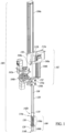
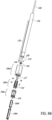
- Figures 1-6 show a mechanical system 100 to pick and/or place specimen containers, according to one illustrated implementation.
- the mechanical system 100 includes a pick and/or place head 102.
- the pick and/or place head 102 is mounted to travel along a first rail 104a.
- the first rail 104a may extend vertically, for example, allowing the pick and/or place head 102 to translate vertically. Such may, for example, allow the pick and/or place head 102 to be moved between an interior and an exterior of an enclosed cryogenic environment (e.g., cryogenic freezer, dewar or other cryogenic enclosure), for example via a door or access port at a top of cryogenic enclosure.
- an enclosed cryogenic environment e.g., cryogenic freezer, dewar or other cryogenic enclosure
- the pick and/or place head 102 includes a receiver 106, a drive shaft 108, an engagement head 110, and one or more actuators, for example a translation motor 112a and a rotation motor 112b.
- the receiver 106 has a proximate end 114a, a distal end 114b, and a receptacle 116 having an opening 118 ( Figure 2 ) at the distal end 114b of the receiver 106.
- the receiver 106 and the receptacle 116 may be formed of two or more parts, although in some implementations the receiver 106 may take the form of a single-piece, unitary structure. As illustrated, the receiver 106 comprises a proximate portion 106a and a distal portion 106b.
- the distal portion 106b of the receiver 106 is illustrated as a block or sleeve 120 with a peripheral flange 122 extending lateral therefrom at a proximate end of the block or sleeve 120 and with a set of feet or standoffs 124 (only one called out in Figure 5 ) extending or projecting longitudinally therefrom at a distal end of the block or sleeve 120.
- the block or sleeve 120 includes the opening 118 which provides access to an interior 126 of the block or sleeve 120.
- the opening 118 and/or the interior 126 of the block or sleeve 120 have a profile that is/are sized and/or shaped to accommodate a profile of a single specimen container 1902 ( Figure 19 ).
- the peripheral flange 122 of the block or sleeve 120 may have throughholes 128 (only one called out in Figure 5 ) to allow the distal portion 106b to be coupled to the proximate portion 106a, for instance via one or more fasteners (not called out in Figures 1-4 , and omitted from Figure 5 ).
- the proximate portion 106a of the receiver 106 is illustrated as a frame or cage 130, comprising a base 132a, a top 132b and frame members or struts 134 that extend between the base 132a and the top 132b, to define an interior 136 therebetween.
- the interior 136 of the proximate portion 106a has a profile that is sized and/or shaped to accommodate a profile of a single specimen container 1902 ( Figure 19 ), although may have higher fit tolerances than that of the interior 126 of the block or sleeve 120 or opening 118.
- the interior 136 of the proximate portion 106a, or a part thereof, may be open to an exterior or alternatively one or more sidewalls may enclose the interior 136.
- the base 132a of the proximate portion 106a may have throughholes to allow the proximate portion 106a to be coupled to the distal portion 106a, for instance via one or more fasteners (e.g., threaded fasteners for instance screws or bolts and nuts).
- the top 132b of the proximate portion 106a may have throughholes (not called out) to allow the proximate portion 106a to be coupled to other portions of the pick and/or place head 102 (described below), for instance via one or more fasteners ((e.g., threaded fasteners for instance screws or bolts and nuts, not called out in Figures 1-4 , and omitted from Figure 5 ).
- the receptacle 116 has a principal axis 138 and a set of lateral inner dimensions 140 measured laterally with respect to the principal axis 138.
- the lateral inner dimensions 140 of the receptacle 116 are sized to accommodate a set of lateral outer dimensions 1914 ( Figure 19 ) of at least a portion of a single container 1902 ( Figure 19 ) therein.
- At least a portion of the receptacle 116 is sized to physically prevent rotation of the single one of the specimen containers 1902 ( Figure 19 ) about the principal axis 138 while allowing translation with respect thereto.
- the lateral inner dimensions 140 of the receptacle 116 at a smallest portion is sized to provide either a clearance fit or close fit (e.g., physically contact without deformation while preventing rotation) with a widest portion of the single container 1902 ( Figure 19 ).
- the receptacle 116 or a portion thereof may have a non-circular profile, for instance a D-shaped profile, rectangular profile, or as illustrated in Figure 5 the receptacle 116 has a square profile with two pairs of parallel sides (e.g., a rectangular cuboid) and rounded or arcuate corners between pairs of the sides. Such may receive a portion or all of a single specimen container 1902 ( Figure 19 ), while preventing rotation of or restraining rotation of the single specimen container 1902 within a set angular range.
- the drive shaft 108 has a proximate end 142a and a distal end 142b.
- the drive shaft 108 is a generally elongate member, and may take a variety of forms that allow transmission of translational displacement and rotation.
- the drive shaft 108 may, for example, take the form of a solid rod or a hollow rod. While illustrated as a cylindrical rod, the drive shaft 108 can have non-circular profiles, for example a D-shaped profile, rectangular profile including a square profile, or a polygonal profile such as a hexagonal or octagonal profile.
- the drive shaft 108 may be made of a metal, or a plastic, or a combination thereof.
- the engagement head 110 is located at the distal end 142b of the driver shaft 108, and translates and rotates along with the drive shaft 108.
- the engagement head 110 may be an integral, unitary part of the drive shaft 108, or may be a separate and distinct part physically coupled or otherwise attached directly, or indirectly to the drive shaft 108.
- the engagement head 110 includes or more engagement features to engage a portion of a single one of the specimen containers 1902 ( Figure 19 ) when the single one of the specimen containers 1902 is positioned in the receptacle 116 of the receiver 106.
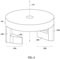
- the engagement head 110 includes a base 144 (called out in Figure 6 ) and a pair of lugs 146a, 146b.
- Each of the lugs 146a, 146b comprises a stem 148a, 148b (called out in Figure 6 ) positioned at diametrically opposed locations at a periphery of the base 144 and extending longitudinally outwardly (e.g., perpendicularly) from the base 144.
- Each of the lugs 146a, 146b comprises a finger 150a, 150b (called out in Figure 6 ) that extends angled radially inwardly from the respective stem 148a, 148b, the fingers 150a, 150b each having a distal most portion that is spaced radially inwardly of the principal axis 138 of the receptacle 116.
- the finger 150a, 150b of each of the lugs 146a, 146b is disposed in a same rotational direction about the principal axis 138 as the finger 150a, 150b of the other one of the lugs 146a, 146b.
- the stems 148a, 148b provide for a gap to exist between the fingers 150a, 150b and the base 144.
- specimen containers 1902 each include a vial and a cap, the cap having a handle, the cap threadedly coupled to vials, and the lugs are disposed about the principal axis 138 such that a counterclockwise rotation of the drive shaft 108 causes the lugs 146a, 146b, and in particular fingers 150a, 150b, to engage the handle of the cap in a direction in which the cap tightens to the vial, and such that a clockwise rotation of the drive shaft 108 causes the lugs 146a, 146b to disengage the handle of the cap.
- the inverse directions would apply.
- the pick and/or place head 102 may optionally include one or more bearings 152 (only one shown in Figures 1 and 3 ) that support the drive shaft 108 for translation along the principal axis and rotation about the principal axis 138 of the receptacle 116.
- the bearing(s) 152 may be supported via one or more brackets 154a ( Figures 1-4 ) attached for example to a support plate 156 ( Figures 1-4 ).
- the pick and/or place head 102 may optionally include a guide tube 158 ( Figures 1-4 ) through which a portion of the drive shaft 108 translates in moving between a retracted position the engagement head 110 and an extended position of the engagement head 110.
- the engagement head 110 is positioned distally with respect to the retracted position, for example positioned to contact and engage a portion (e.g., handle on cap) of the single specimen container 1902 ( Figure 1 ) that is located in the interior of the block or sleeve 120.
- the guide tube 158 may be supported via one or more brackets 154b, for example, attached to the support plate 156.
- the translation motor 112a and a rotation motor 112b may be coupled to the drive shaft 108 via respective drive trains or transmissions 160a, 160b.
- the translation motor 112a may be coupled to a second rail 104b, to drive the drive shaft to translate along the second rail 104b, in what would typically be a vertical direction.
- the translation motor 112a, rotation motor 112b, and/or the respective drive trains or transmissions 160a, 160b ( Figure2 ) may be supported by the support plate 156.
- the actuators of the pick and/or place head 102 can take other forms, for example one or more of the actuators may take the form of one or more solenoids.
- the translation motor 112a and a rotation motor 112b may be controlled or operated via signals supplied by one or more control systems, for instance via one or more motor controllers 1838 ( Figure 18 ).
- the drive shaft 108 is translatable, via the translation motor 112a and respective drive train or transmission 160a, parallel with the principal axis 138 to selectively position the engagement head 110 alternatingly distally from and proximate to a first portion of the single one of the specimen containers 1902 ( Figure 1 ) when the single one of the specimen containers 1902 is positioned at least partially in the receptacle 116 of the receiver 106.
- the drive shaft 108 is selectively rotatable, via the rotation motor 112b and respective drive train or transmission 160b, alternatingly in a clockwise and a counterclockwise direction about the principal axis 138 to cause at least a portion (e.g., lugs 146a, 146b) of the engagement head 110 to alternatingly engage and disengage the first portion of the single one of the specimen containers 1902 while at least a portion of the receptacle 116 of the receiver 106 prevents the single one of the specimen containers 1902 from rotating about the principal axis 138.
- a portion e.g., lugs 146a, 146b
- the pick and/or place head 102 may be driven to translate along the first rail 104a, for example by one or more actuators, for example motors 162a, 162b drivingly coupled via one or more drive trains or transmissions 164a, 164b to translate the pick and/or place head 102.
- the motors 162a, 162b may be controlled or operated via signals supplied by one or more control systems, for instance via one or more motor controllers 1838 ( Figure 18 ).
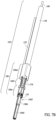
- Figures 7B and 8B show portion of a mechanical system 100 to pick and/or place specimen containers, according to another one illustrated implementation. Some of the components are similar or even identical to those of the implementation of Figures 1-6 , and hence the same reference numbers are employed for similar or identical components. Only some of the significant differences are discussed below. In particular, the receiver 106 in the implementation of Figures 7B and 8B has some differences with respect to the receiver 106 of the implementations of Figures 1-6 , resulting in a simpler to manufacture design.
- a proximate portion 106d of the receiver 106 in the implementation of Figures 7B and 8B is a block with a longitudinally extending cavity.
- the longitudinally extending cavity of the proximate portion 106d can be sized and shaped to receive an upper portion (e.g., cap 1902) of the single specimen container 1902 when drawn upward by the drive shaft 108, and prevent rotation of the single specimen container 1902 about a longitudinal axis when received in the longitudinally extending cavity of the proximate portion 106d.
- a distal portion 106e of the receiver 106 in the implementation of Figures 7B and 8B is similar to the distal portion 106b of the receiver 106 of the implementation of Figures 1-6 , if somewhat more elongated along the longitudinal axis thereof, and with arch shaped slots on the sides between each pair of feet or standoffs 124.
- the distal portion 106e includes a longitudinally extending cavity.
- the longitudinally extending cavity of the distal portion 106e can be sized and shaped to receive a lower portion (e.g., vial portion 1904) of the single specimen container 1902 when drawn upward by the drive shaft 108, and prevent rotation of the vial portion 1904 of single specimen container 1902 about a longitudinal axis when received in the longitudinally extending cavity distal portion 106e.
- a bottom of the vial portion 1904 may extend just beyond flush with respect to the cavity of the distal portion 106e, protruding slightly therefrom.
- An intermediate portion 106f of the receiver 106 in the implementation of Figures 7B and 8B is similar to the proximate portion 106a of the receiver 106 of the implementation of Figures 1-6 .
- the intermediate portion 106f is illustrated as a frame or cage, comprising a set of frame members or struts 134 that extend between the proximate portion 106d and the distal portion 106e, to define an interior 136 therebetween. (Only two of four frame members or struts 134 are visible in Figures 7B and 8B .)
- the interior of the proximate portion 106a has a profile that is sized and/or shaped to accommodate a profile of a single specimen container 1902 ( Figure 19 ).
- the interior of the intermediate portion 106f, or a part thereof, may be open to an exterior or alternatively one or more sidewalls may enclose the interior.
- the intermediate portion 106f may have throughholes to allow the intermediate portion 106f to be coupled to the proximate portion 106d and/or distal portion 106e, for instance via one or more fasteners (e.g., threaded fasteners for instance screws or bolts and nuts).
- FIG. 8B Also visible in Figure 8B is a bushing 127 through which the drive rod 108 is received and rotatably mounted.
- the bushing typically is positioned above the distal end 142b and the engagement head 110of the drive rod 108, and is located in guide tube 158.
- tubing 129 supplies a flow of cryogenic fluid (e.g., liquid nitrogen) to the single specimen container 1902 in the event of an anomaly or error condition.
- a flow of cryogenic fluid e.g., liquid nitrogen
- Such can advantageously flood the single specimen container 1902 with liquid nitrogen in the event that the single specimen container 1902 cannot be successfully picked or placed, or the pick and/or place head 102 otherwise becomes stuck or non-operable.
- the implementations of Figures 1-6 , 7B and 8B can include one or more magnets positioned to exert an upward (i.e., against the force of gravity) magnetic force, directly or indirectly, on the shaft 108, biasing and thereby retaining the shaft 108 in a retracted position unless actively driven downward by a motor (e.g., motors 162a) and thereby preventing the shaft 108 from falling downward in the event of a power failure or other loss of control.
- a motor e.g., motors 162a
- the one or more magnets can, for example take the form of permanent magnets or electric magnets, although permanent magnets may be preferred since such would not be adversely effected in the event of a loss of electrical power.
- the mechanical system 100, the pick and/or place head 102 and/or a control system may include one or more sensors (e.g., mechanical encoders, optical encoders, magnetic encoders, electromagnetic induction encoders, rotary encoders, linear encoders, position encoders, level sensors, cameras, infrared transmitter and receiver pairs, Reed switches, Hall effect sensors, temperature sensors or thermocouples, humidity sensors, force sensors, pressure sensors, load cells, vibration sensors, flow rate or volume sensors) positioned to sense various conditions (e.g., position, orientation, mechanical resistance, presence or absence of frost).
- sensors e.g., mechanical encoders, optical encoders, magnetic encoders, electromagnetic induction encoders, rotary encoders, linear encoders, position encoders, level sensors, cameras, infrared transmitter and receiver pairs, Reed switches, Hall effect sensors, temperature sensors or thermocouples, humidity sensors, force sensors, pressure sensors, load cells, vibration sensors, flow rate or volume sensors
- the mechanical system 100 and/or the pick and/or place head 102 may include one or more defrosters selectively operable to defrost portions of the mechanical system 100, portions of the pick and/or place head 102 and/or the specimen containers 1902 ( Figure 19 ).
- the mechanical system 100 of Figures 1 , 2 , 7B and 8B may include a manual override mechanism that manually dispenses the single one of the specimen containers from the receiver, for example even when frost buildup prevents the at least one actuator from successfully dispensing the single one of the specimen containers from the receiver.
- the manual override mechanism may, for example, include at least one handle, for instance a knob, that extends lateral from the drive shaft.
- the manual override mechanism may optionally include a slot in a side wall of the receiver and a cover that selectively provides access laterally into the interior of the receiver via the side wall, similar in some respects to a bolt action rifle.
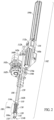
- Figures 7A and 8A show a vacuum-based system 700 to pick and/or place specimen containers from an array of specimen containers, which is illustrate along with a single one of the specimen containers 1902 partially received by a portion of the vacuum-based system 700, according to one illustrated implementation.
- the vacuum-based system 700 includes a pick and/or place head 702.
- the pick and/or place head 702 may be mounted to travel along a rail (e.g., first rail 104a, Figure 1 ).
- the first rail 104a may extend vertically, for example, allowing the pick and/or place head 702 to translate vertically.
- Such may, for example, allow the pick and/or place head 702 to be moved between an interior and an exterior of an enclosed cryogenic environment (e.g., cryogenic freezer, dewar or other cryogenic enclosure), for example via a door or access port at a top of cryogenic enclosure.
- an enclosed cryogenic environment e.g., cryogenic freezer, dewar or other cryogenic enclosure
- the pick and/or place head 702 includes a receiver 706, a drive shaft 708, a vacuum conduit 710.
- the pick and/or place head 702 may include or may be coupled with one or more actuators, for example one or more solenoids or electric motors 1836a, 1836b, 1836c ( Figure 18 ) and/or one or more vacuum source(s) 1842 ( Figure 18 ).
- actuators for example one or more solenoids or electric motors 1836a, 1836b, 1836c ( Figure 18 ) and/or one or more vacuum source(s) 1842 ( Figure 18 ).
- vacuum herein and in the claims refers to a negative pressure, e.g., a pressure below atmospheric pressure or below ambient pressure in the adjacent surroundings, which typically is somewhat above an absolute vacuum or zero pressure.
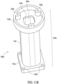
- the receiver 706 has a proximate end 714a, a distal end 714b, and a receptacle 716 (called out in Figure 8 ) having an opening 718b at the distal end 714b of the receiver 706.
- the receiver 706 and the receptacle 716 may be formed of two or more parts, although in some implementations the receiver 706 may take the form of a single-piece, unitary structure. As illustrated, the receiver 706 comprises a proximate portion 706a, a distal portion 706b, and an intermediate portion 706c, the intermediate portion 706c positioned between the proximate portion 706a and the distal portion 706b.
- the distal portion 706b of the receiver 706 is illustrated as a distal block or sleeve 720b with a peripheral flange 722 extending laterally therefrom at a proximate end of the distal block or sleeve 720b and with a set of feet or standoffs 724 extending or projecting longitudinally therefrom at a distal end of the distal block or sleeve 720b.
- the distal block or sleeve 720b includes a through-passage 726b with openings 718b that provide access to an interior of the distal block or sleeve 720b, for example from an exterior of the receiver 706.
- the openings 718b and/or the through-passage 726b of the distal block or sleeve 720b have a profile that is/are sized and/or shaped to accommodate a profile of a single specimen container 1902 ( Figures 7A and 8A ).
- the peripheral flange 722 of the distal block or sleeve 720b may have holes 728b ( e.g., threaded holes, only one called out in Figures 9A and 9B ) to allow the distal portion 706b to be coupled to the intermediate portion 106c, for instance via one or more fasteners ( e.g., threaded fasteners, not called out in Figures 7A and 8A ), and omitted from Figures 9A and 9B ).
- the intermediate portion 706c of the receiver 706 is illustrated as an intermediate block or sleeve 720c.
- the intermediate block or sleeve 720c includes a through-passage 726c with openings 718c that provide access to an interior of the intermediate block or sleeve 720c.
- the openings 718c and/or the through-passage 726c of the intermediate block or sleeve 720c have a profile that is/are sized and/or shaped to accommodate a profile of a single specimen container 1902 ( Figures 7A and 8A ).
- the intermediate block or sleeve 720c may have holes 728c (only two called out in each of Figures 10A and 10B ) to allow the intermediate portion 706c to be coupled to the distal portion 706a and coupled to proximate portion 706b, for instance via one or more fasteners (not called out in Figures 7A and 8A ), and omitted from Figures 10A and 10B ).
- one or more bearings 736 may be coupled to a proximate end of the intermediate portion 706c of the receiver 706.
- the proximate portion 706a of the receiver 106 is illustrated as a proximate block or sleeve 720b.
- the proximate block or sleeve 720a comprises a tubular main body portion 734 with a distal flange 732a extending laterally from a distal end thereof and a proximate flange 732b extending laterally from a proximate end thereof.
- the proximate block or sleeve 720b includes a through-passage 726a with openings 718a that provide access to an interior of the proximate block or sleeve 720a.
- the interior or through-passage 736a of the proximate portion 706a is laterally enclosed, with the opening 718c at the proximate end providing a vacuum port which allows a vacuum or negative pressure to be established in the interior of the proximate portion 706a, which can advantageously be used to draw a single specimen container 1902 ( Figures 7A and 8A ) inwards into the interior of the through-passage 726a from a position in which a portion of the single specimen container 1902 was received in the distal and/or intermediary blocks or sleeves 702a, 720c.
- the distal flange 732a of the proximate portion 706a may have holes 728a (e.g., threaded holes) to allow the proximate portion 706a to be coupled to the intermediate portion 706c, for instance via one or more fasteners (e.g., threaded fasteners, for instance screws or bolts, not illustrated in Figures 11A and 11b ) and/or via one or more bearings 736 ( Figure 10B ) and a pivot plate 1202 (as described below).
- fasteners e.g., threaded fasteners, for instance screws or bolts, not illustrated in Figures 11A and 11b
- bearings 736 Figure 10B
- pivot plate 1202 as described below.
- the proximate flange 732b of the proximate portion 706a may have holes 728a to allow the proximate portion 706b to be coupled to a cover 1402 ( Figures 14A 14B ) of the pick and/or place head 102 (described below), for instance via one or more fasteners (e.g., threaded fasteners, not called out in Figures 1-3 , and omitted from Figures 11A and 11B ).
- fasteners e.g., threaded fasteners, not called out in Figures 1-3 , and omitted from Figures 11A and 11B .
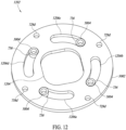
- the proximate end of the proximate portion 706a of the receiver 706 may be coupled to a pivot plate 1202.
- the pivot plate 1202 may, for example, take the form of a disk, and has a central passage 1204.
- the central passage 1204 has a profile that is sized and/or shaped to accommodate a profile of a single specimen container 1902 ( Figures 7A and 8A ).
- the central passage 1204 aligns with the through-passages 726a, 726b, 726c of the proximate portion 706a, distal portion 706b and intermediate portion 706c of the receiver 706 ( Figures 7A and 8A ) such that single specimen container 1902 ( Figures 7A and 8A ) can pass within or extend through the distal portion 706b, intermediate portion 706c, pivot plate 1202, and proximate portion 706a.
- the pivot plate 1202 may also have a number ( e.g., four) of arcuate slots 1206a, 1206b, 1206c, 1206d (collectively 1206) spaced radially outward of central passage 1204.
- the arcuate slots 1206 have a width sized to receive respective ones of the bearings 736.
- the pivot plate 1202 allows pivoting through a defined range of angles.
- the pivot plate 1202 also include a number of holes 728d ( e.g., threaded holes) to allow the pivot plate 1202 to be physically coupled to a torque coupler 1302 ( Figures 13A , 13B ) described below.
- a number of holes 728d e.g., threaded holes
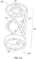
- the torque coupler 1302 has a proximate end 1304a, a distal end 1304b.
- the torque coupler 1302 has an annular base 1306 at the distal end 1304b and a plate 1308 in the form of a disk at the proximate end 1304a.
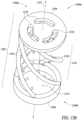
- the torque coupler 1302 has a plurality of strands 1310 (four shown) that couple the annular base 1306 with the plate 1308.
- the strands 1310 are spaced radially outward of a longitudinal axis 1312, to define a space 1314 in which the intermediate portion 706c ( Figures 11A , 11B ) can be received.
- Each of the strands 1310 may, for example, have a helical shape, the plurality of strands 1310 forming a helical cage 1316 about the intermediate portion 706c.
- the plurality of strands 1310 are sufficiently stiff in rotation about the longitudinal axis 1312 to transmit torque, yet may be compliant to axial forces ( e.g., compression and/or tension along the longitudinal axis 1312) to dampen vibration.
- the annular base 1306 at the distal end 1304b of the torque coupler 1302 has a plurality of holes 728e (e.g., threaded holes, Figure 13A ), which allows the annular base 1306 to be physically coupled to the pivot plate 1202 ( Figure 12 ), for instance via fasteners (not shown in Figures 13A , 13B ), for instance threaded screws or bolts.
- holes 728e e.g., threaded holes, Figure 13A
- fasteners not shown in Figures 13A , 13B , for instance threaded screws or bolts.
- the plate 1308 at the proximate end 1304a of the torque coupler 1302 includes a number (e.g., three) arcuate slots 1318 spaced radially outward of the longitudinal axis 1312.
- the arcuate slots 1318 extend through an entire thickness of the plate 1308 so constitute through-slots.
- the arcuate slots 1318 are sized, shaped and/or positioned to receive respective arcuate projections of the cover 1402 ( Figures 14A 14B ) described below, that is itself attached to the proximate portion 706a of the receiver 706 at the proximate end thereof, thereby rotationally coupling the torque coupler 1302 with the intermediate portion 706c of the receiver 706 and providing for fluid (e.g., airflow, negative pressure or vacuum) as described below.
- fluid e.g., airflow, negative pressure or vacuum
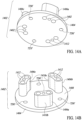
- the cover 1402 includes a base 1404, for example a circular plate having a number of arcuate projections 1406a, 1406b, 1406c (three shown, collectively 1406) extending upwardly ( e.g., perpendicularly from a top surface 1408 of the base 1404.
- the base 1404 may also include a number of holes 728f (e.g., threaded holes), which allows the base 1404 to be fastened to the proximate portion 706a of the receiver 706 at the proximate end thereof, hereby creating a chamber at the proximate end of the proximate portion 706a of the receiver 706.
- the arcuate projections 1406 are spaced radially outward of a longitudinal axis.
- the arcuate projections 1406 may each have an arcuate face 1410a that faces radially toward the longitudinal axis and an arcuate face 1410b that faces radially outward with respect to the longitudinal axis.
- the positions of the arcuate projections 1406 of the cover 1402 both radially and angular about the longitudinal axis, as well as the shape and size of the arcuate projections 1406 of the cover 1402 match the positions and shapes and sizes of the arcuate slots 1318 of the plate 1308 of the torque coupler 1302, to mate with or be closely receive by respective ones of the arcuate slots 1318 of the plate 1308 of the torque coupler 1302.
- Each of the arcuate projections 1406 includes one or more throughholes 1412 (only a few called out) which also pass through the base to provide a conduit for an airflow or pressure (e.g., negative pressure or vacuum, positive pressure) to be applied to the interior (e.g., enclosed cavity) of the intermediate portion of the receiver.
- an airflow or pressure e.g., negative pressure or vacuum, positive pressure
- the cover 1402 may alternatively be described as a manifold.
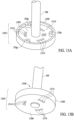
- Proximate-most portions of the arcuate projections 1406 of the cover 1402 interface with a distal surface of a head 1502 (described below) of the drive shaft 708 ( Figures 7A and 8A ), the drive shaft 708 and head 1502 best illustrated in Figures 15A and 15B .
- the drive shaft 708 may take the form of an elongated member, for instance a rod, with a head 1502 at a distal end 1504 of the drive shaft 708.
- the head 1502 may take the form of a plate 1506, for example a disk, with an upstanding peripheral wall or edge 1508 to define a recess or interior volume 15010.
- the drive shaft 708 may terminate at a floor 1512 or may extend through the plate 1506.
- the plate 1506 has a number of throughholes 1514 that are positioned, oriented, sized, and/or shaped to align or couple with respective throughholes 1412 of the cover 1402, to provide a fluidly conductive paths therethrough.
- the head 1502 may also include a number of holes 728g (e.g., threaded holes) which allow the head 1502 to be physically coupled or fastened to a collar 1602 (best illustrated in Figures 16A and 16B ), described below.
- a number of holes 728g e.g., threaded holes
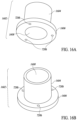
- the collar 1602 includes a stem 1604 with a flange 1606 that extends radially outward from a distal end of the stem 1604 and collar 1602.
- the flange 1606 may include a number of holes 728h (e.g., threaded holes) which allow the collar 1602 to be physically coupled or fastened to the head 1502.
- the collar 1602 and the head 1502 form a cavity therebetween.
- the stem 1604 has a central passage 1608 which provides a fluidly conductive path into an interior of the cavity formed by the collar 1602 and the head 1502.
- a vacuum conduit 710 in the form of a tube or sheath receives a portion the drive shaft 708, allowing rotation of the drive shaft 708 relative to the vacuum conduit 710.
- the vacuum conduit 710 also provides a conduit for airflow, including a negative pressure or even a positive pressure, in a volume of the interior of the vacuum conduit 710 that is not occupied by the drive shaft 708.
- the vacuum conduit 710 may have a coupler 750a at a proximal end thereof to provide a detachable or even permanent coupling to a supply line from a vacuum source (e.g., vacuum pump, Venturi).
- the vacuum conduit 710 may have a coupler 750b at a distal end thereof to provide a detachable or even permanent coupling to the collar 1602.
- the described pick and/or place head 702 of the vacuum-based system 700 provides a fluidly conductive path that allows a pressure (e.g., negative pressure or vacuum, positive pressure) generated or produced by a source to be communicated into the interior of the receiver 706.
- a pressure e.g., negative pressure or vacuum, positive pressure
- a vacuum is supplied at the proximate end of the vacuum conduit 710.
- the vacuum is supplied by the central passage 1608 ( Figures 16A, 16B ) of the collar 1602 into the chamber formed by the head 1502 ( Figures 15A, 15B ) and cover 1402.
- the throughholes 1514 in the base 1506 of the head 1502 supply the vacuum into the interior volume defined at the proximate end of the proximate portion 706a ( Figures 11A , 11B ) of the receiver 706.
- the through-passage 726a of the proximate portion 706a of the receiver 706 fluidly communicatively couples the vacuum from the proximate portion 706a of the receiver 706 to the through-passage 726c of the intermediate portion 706c ( Figures 10A, 10B ) of the receiver 706, which in turn fluidly communicatively couples the vacuum to the through-passage 726b of the distal portion 706b ( Figures 9A, 9B ) of the receiver 706.
- Figure 17 illustrates a portion of the vacuum-based system 700 of Figures 7A and 8A showing a single specimen container 1902 positioned in a receiver 706 thereof, according to at least one illustrated implementation.
- a cap 1906 of the single specimen container 1902 is positioned in the through-passage 726a of the proximal portion 706a of the receiver 706, while most of the vial portion 1904 extends through the through-passages 726c, 726b of the intermediate and distal portions 706c, 706b, respectively, of the receiver 706.
- the cap 1906 may have larger outer dimensions than corresponding outer dimensions of the vial 1904 of the single specimen container 1902.
- the torque coupler 1302 transmits rotation of the drive shaft 708 into rotation of the proximate portion 706a of the receiver 706, while the intermediate and distal portions 706c, 706b of the receiver 706 remain fixed due to the pivot plate 1308.
- the application of torque rotates the proximate portion 706a.
- the internal passage 726a of the proximate portion 706a engages portions of the cap 1906, hence the single specimen container 1902 rotates along with the proximate portion 706a.
- the rotation of the single specimen container 1902 relative to the intermediate and distal portions 706c, 706b, causes a profile of an opening at a proximate end of the intermediate portion 706c and/or through-passage 726c thereof to no longer align with a corresponding profile of a distal portion of the cap 1906 of the single specimen container 1902, and thereby prevents translation of the single specimen container 1902 with respect to the longitudinal axis of the receiver 706. At this point, application of the vacuum may be stopped since translation of the single specimen container 1902 is physically prevented.
- the vacuum-based system 700 of Figures 7A and 8A may include a manual override mechanism that manually dispenses the single one of the specimen containers from the receiver, for example even when frost buildup prevents the at least one actuator from successfully dispensing the single one of the specimen containers from the receiver.
- the manual override mechanism may, for example, include at least one handle, for instance a knob, that extends lateral from the drive shaft.
- the manual override mechanism may optionally include a slot in a side wall of the receiver and a cover that selectively provides access laterally into the interior of the receiver via the side wall, similar in some respects to a bolt action rifle.
- the control system 1802 may include one or more processors, for example one or more of: one or more microprocessors 1804, one or more digital signal processors (DSPs) 1806, one or more application specific integrated circuits (ASICs) and/or one or more field programmable gate array (FPGAs) operable to execute programmed logic.
- the control system 1802 may also include nontransitory processor-readable storage media, for example nonvolatile memory such as read only memory (ROM) and/or FLASH 1808 and/or volatile memory such as random access memory (RAM) 1810.
- ROM/FLASH 1808 and RAM 1810 are communicatively coupled to the microprocessor 1814 via one or more communications channels, for example a power bus, instruction bus, address bus, command bus, etc.
- the microprocessor 1804 executes logic, for example logic stored in the nontransitory processor-readable media (e.g., ROM/FLASH 1806, RAM 1808) as one or more sets of processor-executable instructions and/or data.
- the microprocessor 1804 may also be communicatively coupled to a communications radio 1812 and associated antenna 1814 and/or wired communications port 1816 to provide information and data to external systems and/or to receive instructions therefrom.
- the control system 1802 can include one or more antenna positioned to interrogate the single specimen container.
- the control system 1802 can also include an interrogator, for example a radio frequency identification (RFID) interrogator, communicatively coupled to the one or more antenna and operable to transmit interrogation signals and receive response signals from one or more wireless transponders physically coupled to the single specimen container.
- RFID radio frequency identification
- at least one shield is positioned to shield all specimen containers other than the single specimen container from the at least one antenna, allowing a selected single specimen container to be interrogated and identified.
- control system 1802 may include one or more position sensors 1818 (two shown) communicatively coupled with the processor(s) 1804, 1806.
- the position sensor(s) 1818 may be positioned and/or oriented to detect a position of the pick and/or place head 102 ( Figures 1 , 2 , 7B and 8B ) or pick and/or place head 702 ( Figures 7A and 8A ), for example with respect to one or more specimen containers 1902.
- the position sensor(s) 1818 may be positioned and/or oriented to detect a position of the engagement head 110 ( Figures 1 , 2 , 7B and 8B ) relative to the single one of the specimen containers 1902.
- the position sensor(s) 1818 may be positioned and/or oriented to detect a position of the single one of the specimen containers 1902 with respect to the receiver 106 ( Figures 1 , 2 , 7B and 8B ), 706 ( Figures 7A and 8A ) or portion thereof.
- the processor(s) 1804, 1806 provide control signals based on positions detected by the position sensor(s) 1818, for example providing control signals to at least one actuator (e.g., translation motor) to translate the pick and/or place head 102 ( Figures 1 , 2 , 7B and 8B ) or pick and/or place head 702 ( Figures 7A and 8A ), or a portion thereof ( e.g., drive shaft 108).
- actuator e.g., translation motor
- control system 1802 can employ feedback from one or more encoders to determine an orientation of a specimen container 1902 and/or a handle 1912 on cap 1906 thereof, for example employing timing feedback from the encoder(s) that, for example, represents a stalling of a motor (e.g., rotation motor 162b) on engagement with a portion of the specimen container 1902 to determine the orientation of the specimen container 1902.
- a motor e.g., rotation motor 162b
- control system 1802 may include one or more frost detectors that detects frost build up on one or more portions of the system, the at least one frost detector communicatively coupled with the processor(s) 1804, 1806, wherein with the processor(s) 1804, 1806 provides control signals based at least in part on detected frost build up.
- the frost detectors can take a variety of forms, for example one or more frost sensors 1822 (two shown) and/or one or more resistance sensor(s) 1824.
- the processor(s) 1804, 1806 provide control signals based on frost detected by the frost sensors 1822 and/or resistance sensor(s) 1824, for example providing control signals to at least one actuator (e.g., translation motor, rotation motor) to translate and/or rotate a portion of the pick and/or place head 102 ( Figures 1 , 2 , 7B and 8B ) or pick and/or place head 702 ( Figures 7A and 8B ), for instance to translate or rotate a drive shaft 108, 708.
- actuator e.g., translation motor, rotation motor
- the processor(s) 1804, 1806 provide control signals based on frost detected by the frost sensors 1822 and/or resistance sensor(s) 1824 to, for instance, cause activation of one or more defrosters 1826 (two shown), to defrost a frost build up, for example on a portion of the receiver 106, 706, on a drive shaft 108, 708 and/or a portion of a single specimen container 1902. Additionally or alternatively, the processor(s) 1804, 1806 provide control signals based on frost detected by the frost sensors 1822 and/or resistance sensor(s) 1824 to, for instance cause a notification or alert to be presented, notifying an end user of a potential issue which may require manual service or manual intervention.
- control system 1802 may include one or more optical sensors 1828 (two shown) communicatively coupled with the processor(s) 1804, 1806.
- the optical sensor(s) 1828 may be positioned and/or oriented to detect the single one of the specimen containers 1902 or a portion thereof, and/or to detect or optically read information (e.g., one-dimensional or two-dimensional machine-readable symbols) carried by or on the single one of the specimen containers 1902.
- the optical sensor(s) 1828 may be positioned and/or oriented to detect the single one of the specimen containers 1902 or a portion thereof, and/or to image an interior of the single one of the specimen containers 1902 to determine or assess the contents thereof.
- the optical sensor(s) 1828 may take a variety of forms.
- the optical sensor(s) 1828 may take the form of a linear or two-dimensional array of charged-coupled devices (CCDs), for use with imaging of a machine-readable symbol using ambient lighting or active lighting.
- the optical sensor(s) 1828 may take the form of a photo-diode, for use with "flying spot" machine-readable symbol reader using active lighting in which a spot of light is moved across the machine-readable symbol.
- the information may include information that uniquely identifies the single one of the specimen containers 1902 or the contents thereof.
- One or more processors may be communicatively coupled to the interrogation radio 1832, for example to control a transmitter section and to receive signals (e.g., I/Q signals) from a receiver section of the interrogation radio 1832.
- the DSP 1806 may perform preprocessing on the received signals (e.g., I/Q signals) to extract information (e.g., unique identifier) from the received signals, for example including a baseband filter to filter a baseband from the received signals.
- the interrogation antenna(s) 1834 may be positioned and/or oriented to interrogate wireless transponders (e.g., radio frequency identification (RFID) transponders) carried by or on the single one of the specimen containers 1902 when the single one of the specimen containers 1902 is correctly positioned in the receiver 106, 706, to wirelessly detect or read information encoded in the wireless transponder(s) carried by or on the single one of the specimen containers 1902.
- RFID radio frequency identification
- the information may include information that uniquely identifies the single one of the specimen containers 1902 or the contents thereof.
- the information may, for example, include any one or more of identification information (e.g., unique identifier for the specimen container 1902, the specimen, patient name or identifier and/or date of birth, clinic identifier, clinician identifier, procedure, times, dates).
- identification information e.g., unique identifier for the specimen container 1902, the specimen, patient name or identifier and/or date of birth, clinic identifier, clinician identifier, procedure, times, dates).
- Sensors may, for example, include one or more of contact switches, momentary switches, optical detectors for instance an infrared light emitting diode and sensor pair, range finder, time of flight camera.
- control system 1802 may include one or more electric motors (e.g., stepper motors) 1836a, 1836b, 1836c.
- the electric motors 1836a, 1836b, 1836c may, for example correspond to the translation motor 112a, rotation 112b, and motors 162a, 162b ( Figures 1 , 2 , 7B and 8B ).
- the port(s) 1846 may include any of a large variety of mechanical couplers, for example threaded couplers, bayonet couplers, detents, etc., which may allow detachable physical coupling or even permanent physical coupling.
- the vacuum subsystem 1840 may, for example, include one or more values 1848 operable to control fluid communication between the reservoir 1844 and the port(s) 1846, for example either manually and/or in response to control signals provided by the processor 1804.
- the valves 1848 may take any of a large variety of forms commonly employed with control of fluid flow, and in particular gas flow.
- the control system 1802 may include a user interface (UI) 1852.
- the UI 1852 may include one or more user interface (UI) components, for example one or more switches, triggers, display screens (e.g., LCD display), lights ( e.g., LEDs), speakers, microphones, haptic engines, graphical user interfaces (GUIs) with via a touch-sensitive display screen which displays user-selectable icons operable to allow input to the control system 1802 and/or output from the control system 1802.
- UI components allow a user to control operation and/or optionally to receive information. For example, a user may press a button, key or trigger to cause operation of pick and/or place head 102, 702.
- the pick and/or place head 102 ( Figures 1 , 2 , 7B and 8B ), 702 ( Figures 7A and 8A ) along a rail 104a
- the pick and/or place head 102 ( Figures 1 2 , 7A and 8A ), 702 ( Figures 7A and 8A ) may take the form of an end of arm tool or end effector (not illustrated) mounted to, or part of, a robotic appendage, and the positioning and triggering may be fully automated ( i.e., performed autonomously by a robot), for example as part of a pick and place operation in response to signals from the at least one processor-based control system.
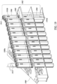
- Figure 19 shows a holder 1900 include a plurality of specimen containers 1902 arranged in an array, according to one illustrated implementation.
- the holder 1900 may include an array of positions 1900a (only one called out) in which respective ones of the specimen containers 1902 may be located and held, for example in a vertical orientation.
- Each specimen container 1902 may comprises a vial 1904 and cap 1906.
- the vial 1904 is generally tubular, and includes one or more walls that delineate an interior or interior volume from an exterior thereof. The wall or a portion thereof may, for example, be transparent.
- the vial 1904 typically includes an opening (not visible) at a top thereof which provides access to the interior from the exterior.
- the vial 1904 may include a coupler feature (not visible) proximate the top thereof to detachable secure the cap 1906 thereto.
- the coupler feature may, for example, take the form of a thread, a detent, or a portion of a bayonet mount.
- the vial 1904 may in some implementations have other non-circular cross-sections or profiles, for example an oval cross-section or profile, a rectangular cross-section or profile, a square cross-section or profile, a D-shape cross-section or profile, hexagonal cross-section or profile, or octagonal cross-section or profile.
- the vial 1904 may have a two or more different cross-sections or profiles that vary from one another along a longitudinal axis or length thereof.
- the cap 1906 couples to the vial at a top thereof, and is moveable to provide and alternatingly prevent access to the interior from the exterior.
- the cap 1906 is completely removably from the vial 1904, while in other implementations the cap 1906 may remain tethered to the vial 1904 even when removed from the opening.
- the cap 1906 may include a complementary coupler feature 1908, that is complementary to the coupler feature of the vial 1904.
- the complementary coupler feature may, for example, take the form of a thread, a detent, or a portion of a bayonet mount sized, positioned or otherwise configured to engagingly mate with the coupler feature of the vial 1904.
- the specimen container 1902 including the vial 1904 and cap 1906 may take any of a large variety of forms, and may be composed of any of a large variety of materials (e.g., plastics), for example materials which are suitable to withstand cryogenic temperatures and/or repeated cycling between room temperatures and cryogenic temperatures.
- the vial 1904 and/or the cap 1906 may include one or more ports 1910 a and/or vents 1910b to allow ingress and egress of fluid (e.g., liquid nitrogen, air) into and out of the interior of the vial.
- the cap 1906 may include one or more engagement features that facilitate engagement, for example a handle 1912.
- the specimen container 1902 has a set of outer dimensions 1914 that represent the outer dimensions of at least one portion (e.g., cap 1906, vial 1904) of the specimen container 1902 measure at one or more positions along a longitudinal axis of the specimen container 1902.
- Figure 19 illustrates a set of outer dimensions 1914 of the cap 1906, which includes a first dimension between outer portions of a first pair of parallel sides, a second dimension between outer portions of a second pair of parallel sides, and a third dimension between outer portions of two corners that extend between perpendicular sides (e.g., third dimension extends across diametrically opposed corners).
- the interior passage 726a of the proximate portion 706a of the receiver 706 may have inner lateral dimensions to closely receive the outer lateral dimensions of the cap 1906.
- the receiver 106 may not restrain rotation of the single one of the specimen containers 1902, relying rather on the engagement head 110 to restrain such.
- the receiver 106 may have inner lateral dimensions to loosely receive the outer lateral dimensions of the cap 1906.
- One or more wireless transponders are physically associated with the specimen container 1902.
- RFID radio frequency identification
- one or more wireless transponders may be physically secured to the vial 1904, for instance molded thereon, secured thereto via adhesive and/or fasteners, or via an interference fit or even a shrink fit.
- one or more wireless transponders may be physically secured to the cap 1906, for instance molded thereon, secured thereto via adhesive and/or fasteners, or via an interference fit or even a shrink fit.
- one or more wireless transponders may, for example, be physically secured to the specimen holders 102, for instance molded thereon, secured thereto via adhesive and/or fasteners, or via an interference fit or even a shrink fit.
- the wireless transponder(s) will have an antenna and will be secured to the such that a principal axis of transmission of the antenna is aligned with the longitudinal axis or length of the vial 1904, although such is not necessary to operation of the described embodiments.
- the antenna of the wireless transponder(s), whether attached to the vial 1904, cap 1906, or specimen holders will also be located at a defined distance along the longitudinal axis or length of the vial 1904 from some fixed point ( e.g., a top of the cap 1906, or top of the vial 1904).
- One or more optically readable symbols may be carried by or inscribed in or on the specimen container 1902.
- machine-readable symbols e.g., one- or two-dimensional machine-readable symbols for instance barcode symbols or QR code symbols
- human-readable symbols e.g., alphanumeric symbols
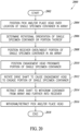
- Figure 20 shows a method 2000 of operating a mechanical system 100 ( Figures 1 , 2 , 7B and 8B ) with a pick and/or place head 102 to pick a single one of the specimen containers from an array of specimen containers, according to at least one illustrated implementation.
- the method may start at 2002, for example in response to a powering ON event, a user input, or an invocation from a calling routine.
- a pick and/or place head 102 is moved to be positioned over a location of selected single specimen container in an array of specimen containers.
- the control system of the mechanical system 100 positions the receiver over/about at least portion of selected single specimen container in an array of specimen containers or portion thereof, with at least the portion of the selected single specimen container received within a portion of receptacle.
- the control system may send signals to a motor controller that causes a motor to translate the pick and/or place head 102 toward ( e.g., downward) the single specimen container until at least a portion of the single specimen container is positioned within the internal passage of a portion of the receiver 106.
- the control system of the mechanical system 100 positions the engagement head proximate a portion (e.g., handle on cap) of the single specimen container.
- the control system may send signals to a motor controller that causes a motor to extend the drive shaft toward ( e.g., downward) the handle on the cap of the single specimen container.
- the control system may translate the drive shaft a defined distance, or may rely on signals from one or more sensors to determine when the engagement head is properly positioned with respect to the portion of the portion of the single specimen container.
- the control system of the mechanical system 100 the rotates the drive shaft to cause a portion (e.g., lugs) of engagement head to engage a portion (e.g., handle on cap) of the single specimen container.
- the control system may send signals to a motor controller that causes the motor to rotate ( e.g., counterclockwise, clockwise) the drive shaft such that the lugs physically engage the handle on the cap of the single specimen container.
- the control system of the mechanical system 100 retracts the drive shaft to withdraw container from array and further into the receiver.
- the control system may send signals to a motor controller that causes a motor to retract the drive shaft (e.g., upward) with the lugs physically engaged with the handle on the cap of the single specimen container.
- the control system may translate the drive shaft a defined distance, or may rely on signals from one or more sensors to determine when the engagement head is properly positioned with respect to a portion of the receiver.
- the control system of the mechanical system 100 withdraws or retracts the pick and/or place head 102, for example to move the pick and/or place head 102 out of the cryogenic freezer or dewar along with the single specimen container located in the receiver.
- the control system may send signals to a motor controller that causes a motor to translate the pick and/or place head 102 away ( e.g., upward) from the array of specimen containers, for example until the pick and/or place head 102 is clear of the array and optionally clear of the cryogenic freezer or dewar.
- the method 2000 may terminate at 2018, for example until invoked again. Alternatively, the method 2000 may repeat to pick or retrieve additional specimen containers from the array of specimen containers.
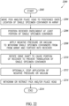
- Figure 21 shows a method 2100 of operating a mechanical system 100 ( Figures 1 , 2 , 7B and 8B ) with a pick and/or place head 102 to place a single one of the specimen containers, according to at least one illustrated implementation.
- the method may start at 2102, for example in response to a powering ON event, a user input, or an invocation from a calling routine.
- a pick and/or place head 102 is moved to be positioned over a destination location at which a single specimen container will be placed, for example placed into an array of specimen containers.
- the control system of the mechanical system 100 positions the pick and/or place head 102 along a Z-axis with respect to the target location.
- the control system may send signals to a motor controller that causes a motor to translate the pick and/or place head 102 toward ( e.g., downward) the target location, positioning a distal end of a receiver proximate the target location.
- the control system of the mechanical system 100 the rotates the drive shaft to cause a portion (e.g., lugs) of engagement head to disengage from a portion (e.g., handle on cap) of the single specimen container.
- the control system may send signals to a motor controller that causes the motor to rotate ( e.g., clockwise, counterclockwise) the drive shaft such that the lugs physically disengage the handle on the cap of the single specimen container.
- the control system of the mechanical system 100 pushes the single specimen container out of the receiver 106.
- the control system may send signals to a motor controller that causes a motor to extend the drive shaft toward ( e.g., downward), for example overcoming any natural resistance or resistance due to the formation of frost.
- the control system may translate the drive shaft a defined distance, or may rely on signals from one or more sensors to determine when the engagement head is properly positioned with respect to pushing the single specimen container out of the receiver.
- the control system of the mechanical system 100 moves the pick and/or place head 102 into a standby position, for example translating the pick and/or place head 102 along the Z-axis, away from the target location.
- the control system may send signals to a motor controller that causes a motor to translate the pick and/or place head 102 away ( e.g., upward) the target location.
- the control system may also, optionally, translate the engagement head of the drive shaft upward to a proximate portion of the receiver.
- the method 2100 may terminate at 2014, for example until invoked again. Alternatively, the method 2100 may repeat to pick or retrieve additional specimen containers from the array of specimen containers.
- Figure 22 shows a method 2200 of operating a vacuum-based system 700 ( Figures 7A and 8A ) with a pick and/or place head 702 to pick a single one of the specimen containers from an array of specimen containers, according to at least one illustrated implementation.
- the method may start at 2202, for example in response to a powering ON event, a user input, or an invocation from a calling routine.
- a pick and/or place head 702 is moved to be positioned over a location of selected single specimen container in an array of specimen containers.
- the control system of the mechanical system 100 positions the receiver over/about at least portion of selected single specimen container in an array of specimen containers or portion thereof, with at least the portion of the selected single specimen container received within a portion of receptacle.
- the control system may send signals to a motor controller that causes a motor to translate the pick and/or place head 702 toward (e.g., downward) the single specimen container until at least a portion of the single specimen container is positioned within the internal passage of a portion of the receiver 706.
- control system of the mechanical system 100 applies a negative pressure or vacuum to withdraw a single one of the specimen containers from array and further into the receiver 706.
- control system may send signals to control a vacuum source and/or a valve controller that causes the negative pressure or vacuum to be applied via the through-passage of the proximate portion 706a of the receiver 706.
- the control system of the mechanical system 100 the rotates the drive shaft to cause a portion of receiver to prevent translation (e.g., downward or outward of receiver) of the single specimen container.
- the control system may send signals to a motor controller that causes the motor to rotate ( e.g., counterclockwise, clockwise) the drive shaft 708 such that the proximate portion 706a of the receiver 706 rotates with respect to an intermediary portion 706c and/or distal portion 706b of the receiver 706, where an inner profile of a through-passage 726c, 726b thereof no longer aligns with an inner profile of a through-passage of the proximate portion 706a and/or an outer profile of the single specimen container.
- the control system of the mechanical system 100 stops the application of the negative pressure or vacuum, with the single one of the specimen containers physically retained in the receiver 706.
- the control system may send signals to control a vacuum source and/or a valve controller that causes application of the negative pressure or vacuum to be stopped.
- the control system of the mechanical system 100 withdraws or retracts the pick and/or place head 702, for example to move the pick and/or place head 702 out of the cryogenic freezer or dewar along with the single specimen container located in the receiver 706.
- the control system may send signals to a motor controller that causes a motor to translate the pick and/or place head 702 away (e.g., upward) from the array of specimen containers, for example until the pick and/or place head 702 is clear of the array and optionally clear of the cryogenic freezer or dewar.
- the method 2200 may terminate at 2216, for example until invoked again. Alternatively, the method 2200 may repeat to pick or retrieve additional specimen containers from the array of specimen containers.
- Figure 23 shows a method 2300 of operating a vacuum-based system 700 ( Figures 7A and 8A ) with a pick and/or place head 702 to place a single one of the specimen containers, according to at least one illustrated implementation.
- the method may start at 2302, for example in response to a powering ON event, a user input, or an invocation from a calling routine.
- a pick and/or place head 702 is moved to be positioned over a destination location at which a single specimen container will be placed, for example placed into an array of specimen containers.
- the control system of the mechanical system 100 positions the pick and/or place head 702 along a Z-axis with respect to the target location.
- the control system may send signals to a motor controller that causes a motor to translate the pick and/or place head 702 toward (e.g., downward) the target location, positioning a distal end of a receiver proximate the target location.
- the control system of the mechanical system 100 stops the application of the negative pressure or vacuum, with the single one of the specimen containers physically retained in the receiver 706.
- the control system may send signals to control a vacuum source and/or a valve controller that causes application of the negative pressure or vacuum to be stopped.
- the control system of the mechanical system 100 the rotates the drive shaft to cause a portion of receiver to stop preventing translation (e.g., downward or outward of receiver) of the single specimen container.
- the control system may send signals to a motor controller that causes the motor to rotate ( e.g., clockwise, counterclockwise) the drive shaft 708 such that the proximate portion 706a of the receiver 706 rotates with respect to an intermediary portion 706c and/or distal portion 706b of the receiver 706, where an inner profile of a through-passage 726c, 726b thereof aligns with an inner profile of a through-passage of the proximate portion 706a and/or an outer profile of the single specimen container.
- the control system of the mechanical system 100 moves the pick and/or place head 702 into a standby position, for example translating the pick and/or place head 702 along the Z-axis, away from the target location.
- the control system may send signals to a motor controller that causes a motor to translate the pick and/or place head 702 away ( e.g., upward) the target location.
- the method 2300 may terminate at 2014, for example until invoked again. Alternatively, the method 2300 may repeat to pick or retrieve additional specimen containers from the array of specimen containers.
Landscapes
- Analytical Chemistry (AREA)
- Immunology (AREA)
- Physics & Mathematics (AREA)
- Health & Medical Sciences (AREA)
- Life Sciences & Earth Sciences (AREA)
- Chemical & Material Sciences (AREA)
- Pathology (AREA)
- General Health & Medical Sciences (AREA)
- Biochemistry (AREA)
- General Physics & Mathematics (AREA)
- Engineering & Computer Science (AREA)
- Robotics (AREA)
- Automatic Analysis And Handling Materials Therefor (AREA)
- Sampling And Sample Adjustment (AREA)
- Medical Preparation Storing Or Oral Administration Devices (AREA)
Claims (15)
- System (100) zum Aufnehmen und/oder Platzieren individueller Probenbehälter (1902) aus und/oder in einer Anordnung von Probenbehältern (1902), wobei das System (100) umfasst:einen Empfänger (106) mit einem proximalen Ende (114a), einem distalen Ende (114b) und einer Aufnahme (116) mit einer Öffnung am distalen Ende (114b) des Empfängers (106), wobei die Aufnahme (116) eine Hauptachse (138) und einen Satz seitlicher Innenabmessungen aufweist, die seitlich in Bezug auf die Hauptachse (138) gemessen werden, wobei die seitlichen Innenabmessungen der Aufnahme (116) dazu bemessen sind, einen Satz seitlicher Außenabmessungen mindestens eines Teils eines einzelnen Behälters (1902) darin aufzunehmen, und mindestens ein Teil der Aufnahme (116) dazu bemessen ist, eine Rotation des einzelnen der Probenbehälter (1902) um die Hauptachse (138) physisch zu verhindern, aber eine Translation relativ dazu zu erlauben;eine Antriebswelle (108) mit einem proximalen Ende (142a) und einem distalen Ende (142b); undeinen Eingriffskopf (110) am distalen Ende (142b) der Antriebswelle (108), der sich zusammen mit der Antriebswelle (108) translatorisch bewegt und rotiert,wobei die Antriebswelle (108) parallel zur Hauptachse (138) translatorisch bewegbar ist, um den Eingriffskopf (110) selektiv abwechselnd distal und proximal zu einem ersten Teil des einzelnen der Probenbehälter (1902) zu positionieren, wenn der einzelne der Probenbehälter (1902) zumindest teilweise in der Aufnahme (116) des Empfängers (106) positioniert ist, und zumindest dann, wenn sie in der Nähe des ersten Teils des einzelnen der Probenbehälter (1902) positioniert ist, die Antriebswelle (108) selektiv abwechselnd im Uhrzeigersinn und gegen den Uhrzeigersinn um die Hauptachse (138) drehbar ist, um zu bewirken, dass zumindest ein Teil des Eingriffskopfes (110) abwechselnd mit dem ersten Teil des einzelnen der Probenbehälter (1902) in Eingriff und außer Eingriff kommt, während zumindest ein Teil der Aufnahme (116) des Empfängers (106) den einzelnen der Probenbehälter (1902) darin hindert, sich um die Hauptachse (138) zu drehen.
- System (100) nach Anspruch 1, bei dem der Empfänger (106) einen proximalen Teil (106a) und einen distalen Teil (106b) aufweist, wobei der distale Teil (106b) an einem distalen Ende des proximalen Teils (106a) positioniert ist, wobei insbesondere mindestens einer von dem proximalen Teil (106a) oder dem distalen Teil (106b) den Teil der Aufnahme (116) enthält, der dazu bemessen ist, eine Rotation des einzelnen der Probenbehälter (1902) um die Hauptachse (138) physisch zu verhindern, aber eine Translation in Bezug auf diese zu erlauben.
- System nach Anspruch 2, wobei der distale Teil (106b) einen Satz von Abstandshaltern (124) enthält, die sich distal erstrecken, um die Öffnung der Aufnahme (116) in einem definierten Abstand von einer ebenen Oberfläche der Anordnung von Behältern (1902) zu halten.
- System (100) nach Anspruch 2, wobei die Probenbehälter röhrenförmige Probenbehälter (1902) sind und in der Anordnung von Probenbehältern (1902) mit einem definierten Abstand zwischen den äußersten Teilen der nächstgelegenen benachbarten röhrenförmigen Probenbehälter (1902) angeordnet sind, und der distale Teil (106b) des Empfängers (106) eine äußere seitliche Abmessung aufweist, die einen definierten Abstand zu allen benachbarten der rohrförmigen Probenbehälter (1902) bereitstellt, wenn einer der rohrförmigen Probenbehälter (1902) in der Aufnahme (116) des Empfängers (106) positioniert ist.
- System (100) nach Anspruch 1, wobei der Eingriffskopf (110) eine Basis (144) und ein Paar Ansätze (146a, 146b) aufweist, wobei optional jeder der Ansätze (146a, 146b) einen Schaft (148a, 148b), der sich von der Basis (144) nach unten erstreckt, und einen Finger (150a, 150b) aufweist, der sich von dem Schaft (148a, 148b) radial nach innen erstreckt, wobei der Finger (150a, 150b) einen distalsten Teil hat, der radial einwärts der Hauptachse (138) beabstandet ist, wobei der Finger (150a, 150b) jedes der Ansätze (146a, 146b) optional in einer gleichen Drehrichtung um die Hauptachse (138) wie der Finger (150a, 150b) des anderen der Ansätze (146a, 146b) angeordnet ist.
- System (100) nach Anspruch 5, bei dem die Probenbehälter (1902) jeweils ein Fläschchen (1904) und eine Kappe (1906) umfassen, wobei die Kappe (1906) einen Griff (1912) aufweist, die Kappe (1906) mit dem Fläschchen (1904) verschraubt ist und die Ansätze (146a, 146b) so um die Hauptachse (138) angeordnet sind, dass eine Drehung der Antriebswelle (108) gegen den Uhrzeigersinn bewirkt, dass die Ansätze (146a, 146b) mit dem Griff (1912) der Kappe (1906) in einer Richtung in Eingriff kommen, in der die Kappe (1906) an dem Fläschchen (1904) festgezogen wird, und dass eine Drehung der Antriebswelle (108) im Uhrzeigersinn bewirkt, dass die Ansätze (146a, 146b) mit dem Griff (1912) der Kappe (1906) außer Eingriff kommen.
- System (100) nach Anspruch 1, ferner umfassend:einen oder mehrere Aktuatoren (112a, 112b), die antriebsmäßig gekoppelt sind, um die Translation und Rotation der Antriebswelle (108) und des Eingriffskopfes (110) zu steuern, undmindestens ein prozessorbasiertes Steuersystem (1802), das kommunikativ gekoppelt ist, um den einen oder die mehreren Aktuatoren (112a, 112b) zu steuern.
- System (100) nach Anspruch 7, ferner umfassend:
mindestens einen Positionssensor (1818), der dazu positioniert ist, eine Position des Eingriffskopfes (110) relativ zu dem einzelnen der Probenbehälter (1902) zu erfassen, wobei der mindestens eine Positionssensor (1818) kommunikativ mit dem mindestens einen prozessorbasierten Steuersystem (1802) gekoppelt ist, wobei das mindestens eine prozessorbasierte Steuersystem (1802) Steuersignale an den einen oder die mehreren Aktuatoren (112a, 112b) liefert, um den Eingriffskopf (110) translatorisch in Bezug auf den ersten Teil des Probenbehälters (1902) zu positionieren. - System (100) nach Anspruch 7, ferner umfassend:
mindestens einen Ausrichtungssensor (1820), der dazu positioniert ist, eine Ausrichtung des einzelnen der Probenbehälter (1902) relativ zu dem Eingriffskopf (110) zu erfassen, wobei der mindestens eine Ausrichtungssensor (1820) kommunikativ mit dem mindestens einen prozessorbasierten Steuersystem (1802) gekoppelt ist, wobei das mindestens eine prozessorbasierte Steuersystem (1802) Steuersignale an den einen oder die mehreren Aktuatoren (112a, 112b) liefert, um mindestens einen von dem Empfänger (106), der Aufnahme (116) oder dem Eingriffskopf (110) in Bezug auf den ersten Teil des Probenbehälters (1902) rotationsmäßig auszurichten. - System (100) nach Anspruch 7, ferner umfassend:mindestens einen Frostdetektor (1822), der Frostaufbau auf einem oder mehreren Teilen des Systems (100) erfasst, wobei der mindestens eine Frostdetektor kommunikativ mit dem mindestens einen prozessorbasierten Steuersystem (1802) gekoppelt ist, wobei das mindestens eine prozessorbasierte Steuersystem (1802) Steuersignale liefert, die zumindest teilweise auf dem erfassten Frostaufbau basieren, und optionalmindestens eine Entfrostereinrichtung (1826), die mindestens eine Wärmequelle (1850) umfasst, die selektiv betreibbar ist, um Wärme an mindestens einer Stelle in dem System (100) bereitzustellen, wobei die mindestens eine Entfrostereinrichtung (1826) kommunikativ mit dem mindestens einen prozessorbasierten Steuerungssystem (1802) gekoppelt ist.
- System (100) nach einem der Ansprüche 7 bis 10, wobei der Empfänger (106), die Antriebswelle (108) und der Eingriffskopf (110) zumindest einen Teil eines Aufnehm- und/oder Platzierungskopfes (102) bilden, und ferner umfassend:eine Schiene (104a, 104b), auf der der Aufnehm- und/oder Platzierungskopf (102) translatorisch bewegbar montiert ist; undeinen oder mehrere Aktuatoren (112a, 112b), die antriebsmäßig gekoppelt sind, um die Translation des Aufnehm- und/oder Platzierungskopfes (102) als Reaktion auf Signale von dem mindestens einen prozessorbasierten Steuersystem (1802) zu steuern.
- System (100) nach einem der Ansprüche 1 bis 10, ferner umfassend:
einen manuellen Vorrangsteuerungsmechanismus, der den einzelnen der Probenbehälter (1902) manuell aus dem Empfänger (106) ausgibt, selbst wenn Frostbildung verhindert, dass der mindestens eine Aktuator den einzelnen der Probenbehälter (1902) erfolgreich aus dem Empfänger (106) ausgibt, wobei der manuelle Vorrangsteuerungsmechanismus mindestens einen Griff umfasst, der sich seitlich von der Antriebswelle (108) erstreckt, und optional einen Schlitz in einer Seitenwand des Empfängers (106) umfasst, der selektiv Zugang zu einem Inneren des Empfängers (106) bereitstellt. - System (100) nach einem der Ansprüche 7 bis 10, wobei der Empfänger (106), die Antriebswelle (108) und der Eingriffskopf (110) alle Teil eines Aufnehm- und/oder Platzierungskopfes (102) sind und wobei, um den einzelnen der Probenbehälter (1902) aus einer Anordnung der Probenbehälter (1902) aufzunehmen, das mindestens eine prozessorbasierte Steuersystem (1802) die Aktuatoren (112a, 112b) steuert, um:i) den Aufnehm- und/oder Platzierungskopf (102) in die Nähe des einen der Probenbehälter (1902) zu bewegen;ii) zumindest den distalen Teil (106b) des Empfängers (106) translatorisch zu bewegen, um zumindest einen Teil des einzelnen der Probenbehälter (1902) zu umfassen;iii) die Antriebswelle (108) von einer eingefahrenen Position in eine ausgefahrene Position translatorisch zu bewegen, um den Eingriffskopf (110) in der Nähe des zweiten Teils des einzelnen der Probenbehälter (1902) zu positionieren;iv) die Antriebswelle (108) in einer ersten Drehrichtung um die Hauptachse (138) zu drehen, um den zweiten Teil des einzelnen der Probenbehälter (1902) mit dem Eingriffskopf (110) in Eingriff zu bringen, während der zumindest eine Teil der Aufnahme (116) des Empfängers (106) den einzelnen der Probenbehälter (1902) daran hindert, sich um die Hauptachse (138) zu drehen;v) die Antriebswelle (108) von der ausgefahrenen Position in die eingefahrene Position translatorisch zu bewegen, um den einzelnen der Probenbehälter (1902) weiter in den Empfänger (106) zu ziehen, undvi) den Aufnehm- und/oder Platzierungskopfes (102) translatorisch weg von der Anordnung der Probenbehälter (1902) zu bewegen.
- System (100) nach einem der Ansprüche 7 bis 10, wobei der Empfänger (106), die Antriebswelle (108) und der Eingriffskopf (110) alle Teil eines Aufnehm- und/oder Platzierungskopfes (102) sind, und wobei, um den einzelnen der Probenbehälter (1902) an einem Zielort zu platzieren, das mindestens eine prozessorbasierte Steuersystem (1802) der mindestens eine Aktuator (112a, 112b) steuert, um:i) den Aufnehm- und/oder Platzierungskopf (102) translatorisch über den Zielort zu bewegen;ii) den Aufnehm- und/oder Platzierungskopf (102) translatorisch in eine Position zu bewegen, in der sich zumindest der Empfänger (106) in der Nähe des Zielortes befindet;iii) die Antriebswelle (108) in einer zweiten Drehrichtung um die Hauptachse (138) zu drehen, um den zweiten Teil des einzelnen der Probenbehälter (1902) außer Eingriff mit dem Eingriffskopf (110) zu bringen, während der zumindest eine Teil der Aufnahme (116) des Empfängers (106) den einzelnen der Probenbehälter (1902) daran hindert, sich um die Hauptachse (138) zu drehen;iv) den Aufnehm- und/oder Platzierungskopf (102) translatorisch weg von der Position, in der sich zumindest der Empfänger (106) in der Nähe des Zielortes befindet, zu bewegen.
- System (100) nach Anspruch 14, wobei, um den einzelnen der Probenbehälter (1902) an einem Zielort zu platzieren, das mindestens eine prozessorbasierte Steuersystem (1802) den mindestens einen Aktuator (112a, 112b) steuert, um die Antriebswelle (108) translatorisch von der eingefahrenen Position in die ausgefahrene Position zu bewegen, um den einzelnen der Probenbehälter (1902) aus dem Empfänger (106) herauszuschieben, nachdem iii) die Antriebswelle (108) in der zweiten Drehrichtung um die Hauptachse (138) gedreht wurde, um den zweiten Teil des einzelnen der Probenbehälter (1902) außer Eingriff mit dem Eingriffskopf (110) zu bringen, und bevor iv) der Aufnehm- und/oder Platzierungskopf (102) translatorisch weg von der Position, in der sich zumindest der Empfänger (106) in der Nähe des Zielortes befindet, bewegt wurde.
Applications Claiming Priority (2)
| Application Number | Priority Date | Filing Date | Title |
|---|---|---|---|
| US202163136886P | 2021-01-13 | 2021-01-13 | |
| PCT/US2022/012151 WO2022155225A1 (en) | 2021-01-13 | 2022-01-12 | Systems, apparatus and methods to pick and/or place specimen containers |
Publications (3)
| Publication Number | Publication Date |
|---|---|
| EP4252009A1 EP4252009A1 (de) | 2023-10-04 |
| EP4252009A4 EP4252009A4 (de) | 2024-04-03 |
| EP4252009B1 true EP4252009B1 (de) | 2025-03-05 |
Family
ID=82321762
Family Applications (1)
| Application Number | Title | Priority Date | Filing Date |
|---|---|---|---|
| EP22739992.0A Active EP4252009B1 (de) | 2021-01-13 | 2022-01-12 | System zur entnahme und/oder platzierung von probenbehältern |
Country Status (6)
| Country | Link |
|---|---|
| US (1) | US12259399B2 (de) |
| EP (1) | EP4252009B1 (de) |
| JP (1) | JP7587316B2 (de) |
| AU (1) | AU2022207973B2 (de) |
| CA (1) | CA3202347A1 (de) |
| WO (1) | WO2022155225A1 (de) |
Families Citing this family (5)
| Publication number | Priority date | Publication date | Assignee | Title |
|---|---|---|---|---|
| US6371223B2 (en) | 1999-03-03 | 2002-04-16 | Earth Tool Company, L.L.C. | Drill head for directional boring |
| MX2022005127A (es) | 2019-10-29 | 2022-08-04 | Tmrw Life Sciences Inc | Aparato para facilitar la transferencia de especimenes biologicos almacenados en condiciones criogenicas. |
| AU2021276247A1 (en) | 2020-05-18 | 2022-11-17 | TMRW Life Sciences, Inc. | Handling and tracking of biological specimens for cryogenic storage |
| JP7610303B2 (ja) | 2020-09-24 | 2025-01-08 | ティーエムアールダブリュ ライフサイエンシーズ,インコーポレイテツド | 極低温条件で保管された生物学的試料の移送を容易にするためのワークステーション及び装置 |
| CN116660196A (zh) * | 2023-06-13 | 2023-08-29 | 安徽光智科技有限公司 | 一种制冷测试仪器、测试系统和测试方法 |
Family Cites Families (249)
| Publication number | Priority date | Publication date | Assignee | Title |
|---|---|---|---|---|
| US4573581A (en) | 1983-07-18 | 1986-03-04 | Network Medical Containers Pty, Ltd. | Environmentally controlled medication container |
| US5024830A (en) | 1983-08-23 | 1991-06-18 | The Board Of Regents, The University Of Texas | Method for cryopreparing biological tissue for ultrastructural analysis |
| JPH0611448Y2 (ja) * | 1988-03-25 | 1994-03-23 | 照明 伊藤 | 試験管保存管理装置 |
| US4969336A (en) | 1989-08-04 | 1990-11-13 | Cryo-Cell International, Inc. | Cryogenic storage apparatus, particularly with automatic retrieval |
| US5176202A (en) | 1991-03-18 | 1993-01-05 | Cryo-Cell International, Inc. | Method and apparatus for use in low-temperature storage |
| US5355684A (en) | 1992-04-30 | 1994-10-18 | Guice Walter L | Cryogenic shipment or storage system for biological materials |
| US5545562A (en) | 1994-05-31 | 1996-08-13 | Instruments De Medecine Veterinaire | Device for identifying straws for cryogenic storage of biological liquids |
| DE9416270U1 (de) | 1994-10-10 | 1994-12-08 | Grieb, Reinhard, 63633 Birstein | Laborprobenbehälter |
| US5638686A (en) | 1995-02-23 | 1997-06-17 | Thermogenesis Corporation | Method and apparatus for cryogenic storage of thermolabile products |
| US5964095A (en) | 1995-02-23 | 1999-10-12 | Thermogenesis Corp. | Method and apparatus for cryogenic storage of thermolabile products |
| US5751629A (en) | 1995-04-25 | 1998-05-12 | Irori | Remotely programmable matrices with memories |
| US5874214A (en) | 1995-04-25 | 1999-02-23 | Irori | Remotely programmable matrices with memories |
| US6100026A (en) | 1995-04-25 | 2000-08-08 | Irori | Matrices with memories and uses thereof |
| US6329139B1 (en) | 1995-04-25 | 2001-12-11 | Discovery Partners International | Automated sorting system for matrices with memory |
| US5925562A (en) | 1995-04-25 | 1999-07-20 | Irori | Remotely programmable matrices with memories |
| US5741462A (en) | 1995-04-25 | 1998-04-21 | Irori | Remotely programmable matrices with memories |
| US5921102A (en) | 1997-03-28 | 1999-07-13 | Cryo-Cell International, Inc. | Storage apparatus particularly with automatic insertion and retrieval |
| US6302327B1 (en) | 1997-06-16 | 2001-10-16 | Thermogenesis, Corp. | Method and apparatus for cryogenic storage of thermolabile products |
| US5884640A (en) | 1997-08-07 | 1999-03-23 | Applied Materials, Inc. | Method and apparatus for drying substrates |
| US6156566A (en) | 1997-10-17 | 2000-12-05 | Bryant; Debra L. | In vitro fertilization procedure dish |
| JP3921845B2 (ja) | 1998-10-30 | 2007-05-30 | 株式会社島津製作所 | 試料冷却装置 |
| JP2003505311A (ja) | 1999-07-15 | 2003-02-12 | ザ テクノロジー パートナーシップ ピーエルシー | 貯蔵取出システム |
| US6714121B1 (en) | 1999-08-09 | 2004-03-30 | Micron Technology, Inc. | RFID material tracking method and apparatus |
| JP2001142861A (ja) | 1999-11-15 | 2001-05-25 | Mitsubishi Electric Corp | マルチプロセッサシステム |
| US6564120B1 (en) | 2000-05-11 | 2003-05-13 | Cryo-Cell International, Inc. | Storage system, particularly with automatic insertion and retrieval |
| GB0013619D0 (en) | 2000-06-06 | 2000-07-26 | Glaxo Group Ltd | Sample container |
| US7070053B1 (en) | 2000-09-05 | 2006-07-04 | Cv Holdings Llc | System, method, and apparatuses for maintaining, tracking, transporting and identifying the integrity of a disposable specimen container with a re-usable transponder |
| AU2001288799A1 (en) | 2000-09-05 | 2002-03-22 | Capitol Vial, Inc. | A system and mathod for maintaining, tracking and identifying the integrity of adisposable specimen container with a re-usable transponder |
| US20020183882A1 (en) | 2000-10-20 | 2002-12-05 | Michael Dearing | RF point of sale and delivery method and system using communication with remote computer and having features to read a large number of RF tags |
| DE60233310D1 (de) | 2001-04-02 | 2009-09-24 | Point 2 Point Genomics Ltd | Analyse von polynukleotiden mittels kombinatorischer pcr |
| DE10202304A1 (de) | 2002-01-22 | 2003-07-31 | Fraunhofer Ges Forschung | Kryospeichereinrichtung mit Transponder |
| ATE314976T1 (de) | 2002-05-07 | 2006-02-15 | Capitol Plastic Products Llc | System, verfahren und vorrichtungen zur aufrechterhaltung, verfolgung, förderung und identifizierung der integrität eines einweg- probenbehälters mit einem wiederverwendbaren transponder |
| JP3890263B2 (ja) | 2002-06-21 | 2007-03-07 | 株式会社エスアールエル | 被検出物感知システム及び被検出物抜き差し感知システム |
| ES2266857T3 (es) | 2002-09-23 | 2007-03-01 | Integrated Biosystems Inc. | Sistemas y procedimientos para congelar, almacenar, transportar y descongelar material biofarmaceutico. |
| JP4355186B2 (ja) | 2003-04-15 | 2009-10-28 | 株式会社北里サプライ | 卵凍結保存用具 |
| JP4128491B2 (ja) | 2003-06-16 | 2008-07-30 | 株式会社エスアールエル | 検体ラック及び検体位置認識システム |
| US20050058483A1 (en) | 2003-09-12 | 2005-03-17 | Chapman Theodore A. | RFID tag and printer system |
| JP2005239366A (ja) | 2004-02-26 | 2005-09-08 | Nippon Signal Co Ltd:The | 什器リーダライタ |
| WO2005093641A1 (en) | 2004-03-26 | 2005-10-06 | Universite Libre De Bruxelles | Biological samples localisation, identification and tracking, system and method using electronic tag |
| WO2005098455A1 (de) | 2004-04-07 | 2005-10-20 | Tecan Trading Ag | Vorrichtung und vefahren zum identifizieren, orten und verfolgen von objekten auf laboreinrichtungen |
| US20060099567A1 (en) | 2004-04-08 | 2006-05-11 | Biomatrica, Inc. | Integration of sample storage and sample management for life science |
| US7350703B2 (en) | 2004-04-23 | 2008-04-01 | Ambartsoumian Gourgen | Low temperature radio frequency identification tracking system |
| US7323990B2 (en) | 2004-04-27 | 2008-01-29 | Sencorp Inc. | Method and apparatus for placing ID tags in molded articles |
| JP2005321935A (ja) | 2004-05-07 | 2005-11-17 | Toyo Seikan Kaisha Ltd | Icタグ内蔵キャップ |
| WO2005109332A1 (en) | 2004-05-12 | 2005-11-17 | Ivf Limited | Identification of cryo-preserved samples |
| EP1726362A1 (de) | 2005-05-24 | 2006-11-29 | IVF Limited | Vorrichtung zum Datenaustausch mit einem Speicherchip und mit einer temperaturkontrollierten Oberfläche |
| GB0411577D0 (en) | 2004-05-24 | 2004-06-23 | Ivf Ltd | Identification of biological samples |
| US7278328B2 (en) | 2004-09-03 | 2007-10-09 | Protedyne Corporation | Method and apparatus for handling sample holders |
| US7870748B2 (en) | 2005-02-25 | 2011-01-18 | Byrne Kathleen H | Method for controlled rate freezing and long term cryogenic storage |
| US7275682B2 (en) | 2005-03-24 | 2007-10-02 | Varian, Inc. | Sample identification utilizing RFID tags |
| DK2292332T3 (en) | 2005-05-24 | 2016-10-24 | Res Instr Ltd | workstation |
| US7411508B2 (en) | 2005-06-17 | 2008-08-12 | Perkinemer Las, Inc. | Methods and systems for locating and identifying labware using radio-frequency identification tags |
| JP2007041666A (ja) | 2005-08-01 | 2007-02-15 | Ricoh Co Ltd | Rfidタグ及びその製造方法 |
| US8346382B2 (en) | 2005-08-25 | 2013-01-01 | Coldtrack, Llc | Hierarchical sample storage system |
| US20070068208A1 (en) | 2005-09-27 | 2007-03-29 | B&G Plastics, Inc. | Electronic tag housing for support on a bottle bottom |
| US7732202B2 (en) | 2005-10-21 | 2010-06-08 | International Stem Cell Corporation | Oxygen tension for the parthenogenic activation of human oocytes for the production of human embryonic stem cells |
| GB0521702D0 (en) | 2005-10-25 | 2005-11-30 | Bryant Keith C | Rfid enabled plastic container |
| DK2682189T3 (en) | 2006-01-23 | 2015-06-01 | Nexus Biosystems Inc | Automated system for storage, retrieval and administration of samples |
| US10697987B2 (en) | 2006-01-23 | 2020-06-30 | Brooks Automation, Inc. | Automated system for storing, retrieving and managing samples |
| US8097199B2 (en) | 2006-02-07 | 2012-01-17 | Rexam Healthcare Packaging Inc. | Molded plastic container and preform having insert-molded insert |
| JP4013983B2 (ja) | 2006-06-05 | 2007-11-28 | 松下電器産業株式会社 | 無線装置及びプログラム |
| US20080012687A1 (en) | 2006-06-29 | 2008-01-17 | Rubinstein Walter M | Container with embedded rfid tag |
| JP4840917B2 (ja) | 2006-07-12 | 2011-12-21 | 日本クラウンコルク株式会社 | Icタグ付蓋体 |
| US7688207B2 (en) | 2006-07-28 | 2010-03-30 | Abbott Laboratories Inc. | System for tracking vessels in automated laboratory analyzers by radio frequency identification |
| WO2008024471A2 (en) | 2006-08-24 | 2008-02-28 | Kevin Lloyd | Laboratory information management using radio frequency identification |
| WO2008032314A2 (en) | 2006-09-11 | 2008-03-20 | I.M.T. Interface Multigrad Technology Ltd. | Systems, devices and methods for freezing and thawing biological materials |
| EP1916492A1 (de) | 2006-10-25 | 2008-04-30 | Air Liquide Sanità Service S.p.A. | System zur Regelung einer Kryokonservierungsanlage |
| US7586417B2 (en) | 2006-11-10 | 2009-09-08 | Rexam Healthcare Packaging Inc. | RFID insert with disable feature and container that includes such an insert |
| DE102007013237A1 (de) | 2007-03-15 | 2008-09-18 | Joint Analytical Systems Gmbh | Lagersystem |
| US20080239478A1 (en) | 2007-03-29 | 2008-10-02 | Tafas Triantafyllos P | System for automatically locating and manipulating positions on an object |
| GB2450531B (en) | 2007-06-29 | 2012-02-29 | Avonwood Dev Ltd | An RFID monitoring system |
| EP2017606A1 (de) * | 2007-07-16 | 2009-01-21 | Commissariat A L'energie Atomique | Verfahren und Greifvorrichtung zur automatischen Übertragung eines Probenbehälters von einem Lagerort zu einem Analyseort und Verwendung der besagten Vorrichtung |
| US20090027202A1 (en) | 2007-07-27 | 2009-01-29 | Sensormatic Electronics Corporation | Rfid system with integrated switched antenna array and multiplexer electronics |
| US7861540B2 (en) | 2008-01-25 | 2011-01-04 | Hamilton Storage Technologies, Inc. | Automated storage and retrieval system for storing biological or chemical samples at ultra-low temperatures |
| WO2009113694A1 (ja) | 2008-03-13 | 2009-09-17 | Nakahana Yoko | 試料収納体 |
| US8098162B2 (en) | 2008-03-27 | 2012-01-17 | Rexam Healthcare Packaging Inc. | Attachment of an RFID tag to a container |
| EP2124171B1 (de) | 2008-05-22 | 2012-08-01 | Bluechiip Ltd | Etikettierverfahren und Vorrichtung |
| CN102037364B (zh) * | 2008-05-22 | 2014-06-11 | 株式会社日立高新技术 | 样本前处理系统 |
| EP2505511B1 (de) | 2008-06-20 | 2013-07-31 | Toyo Seikan Kaisha, Ltd. | Harzkappe mit Chipetikett |
| US8884743B2 (en) | 2008-06-26 | 2014-11-11 | Bluechiip Pty Ltd | RFID memory devices |
| US8710958B2 (en) | 2008-07-10 | 2014-04-29 | Abbott Laboratories | Containers having radio frequency identification tags and method of applying radio frequency identification tags to containers |
| US8176747B2 (en) | 2008-07-31 | 2012-05-15 | Hamilton Storage Technologies, Inc. | Tube picking mechanism for an automated, ultra-low temperature storage and retrieval system |
| CN102187363B (zh) | 2008-08-15 | 2015-10-07 | 英派尔科技开发有限公司 | 对来自聚合材料的能量或环境信用进行货币化及交易的系统和方法 |
| WO2010037166A1 (en) | 2008-10-03 | 2010-04-08 | Bluechiip Pty Ltd | Ringup/ ringdown interrogation of rfid tags |
| DE102008057981B4 (de) | 2008-11-19 | 2010-09-02 | Fraunhofer-Gesellschaft zur Förderung der angewandten Forschung e.V. | Kryospeichereinrichtung |
| US8035485B2 (en) | 2008-11-20 | 2011-10-11 | Abbott Laboratories | System for tracking vessels in automated laboratory analyzers by radio frequency identification |
| US20100141384A1 (en) | 2008-12-04 | 2010-06-10 | Yeh-Shun Chen | Bottle cap having anti-counterfeit function and bottle using the same |
| US8790597B2 (en) | 2009-05-04 | 2014-07-29 | The United States of Americas, as represented by the Secretary, Department of Health and Human Services | Selective access to cryopreserved samples |
| US8378827B2 (en) | 2009-05-27 | 2013-02-19 | Biotillion, Llc | Two-dimensional antenna configuration |
| US8658236B2 (en) | 2009-08-21 | 2014-02-25 | Deuteria Beverages, Llc | Alcoholic compositions having a lowered risk of acetaldehydemia |
| DK3598140T3 (da) | 2009-10-19 | 2024-06-17 | Brooks Automation Inc | Modulært prøvelager og fremgangsmåde til lagring og tilvejebringelse af prøver |
| EP2498968B1 (de) | 2009-11-11 | 2015-09-23 | Balluff GmbH | Spritzgiessverfahren für das aussengehäuse eines objekts, objekt und spritzgiessvorrichtung |
| WO2011069190A1 (en) | 2009-12-07 | 2011-06-16 | Bluechiip Pty Ltd | Sample storage and monitoring system |
| WO2011070973A1 (ja) | 2009-12-08 | 2011-06-16 | 学校法人北里研究所 | 動物の胚または卵子のガラス化保存用細管 |
| DE102010007686A1 (de) | 2010-02-08 | 2011-08-11 | Askion GmbH, 07549 | Vorrichtung zur Einstellung tiefkalter Temperaturen |
| US8872627B2 (en) | 2010-02-12 | 2014-10-28 | Biotillion, Llc | Tracking biological and other samples using RFID tags |
| US8937550B2 (en) | 2010-04-14 | 2015-01-20 | Eagile, Inc. | Container seal with radio frequency identification tag, and method of making same |
| US10156386B2 (en) | 2010-05-12 | 2018-12-18 | Brooks Automation, Inc. | System and method for cryogenic cooling |
| CN102329725A (zh) | 2010-06-16 | 2012-01-25 | 三星泰科威株式会社 | 光透射温度控制装置、生物诊断设备和方法 |
| US20110308271A1 (en) | 2010-06-18 | 2011-12-22 | Biocision, Inc. | Specimen freezing rate regulator device |
| USD642697S1 (en) | 2010-06-28 | 2011-08-02 | Vitrolife Sweden Ab | Freezer box |
| US9163869B2 (en) | 2010-09-09 | 2015-10-20 | Hamilton Storage Technologies, Inc. | Tube picking mechanisms with an ultra-low temperature or cryogenic picking compartment |
| WO2012033994A2 (en) | 2010-09-10 | 2012-03-15 | Hamilton Storage Technologies, Inc. | Sample storage cassette for ultra-low or cryogenic temperatures |
| WO2012061229A1 (en) | 2010-11-01 | 2012-05-10 | 3M Innovative Properties Company | Biological sterilization indicator system and method |
| BRPI1005702B1 (pt) | 2010-12-21 | 2020-02-04 | Inprenha Biotecnologia E Desenvolvimento Avancado Ltda Me | método para aumentar a taxa de implantação de embriões no útero materno em mamíferos, uso de uma quantidade eficaz de uma lectina ligante de beta-galactosídeo ou derivados da mesma e produto |
| US8168138B2 (en) | 2010-12-22 | 2012-05-01 | Li Che | Cryogenic vial |
| US8709359B2 (en) | 2011-01-05 | 2014-04-29 | Covaris, Inc. | Sample holder and method for treating sample material |
| US9208365B2 (en) | 2011-01-12 | 2015-12-08 | Intermec Ip Corp. | Method and apparatus to mitigate multipath in RFID |
| EP2668820A4 (de) | 2011-01-28 | 2017-11-29 | Bluechiip Pty Ltd | Temperaturmessung und heizvorrichtung |
| DE102011012887B4 (de) | 2011-02-28 | 2012-09-20 | Askion Gmbh | Kryospeichereinrichtung |
| US9431692B2 (en) | 2011-04-07 | 2016-08-30 | Biotillion, Llc | Tracking biological and other samples using RFID tags |
| WO2012158963A2 (en) | 2011-05-18 | 2012-11-22 | Biocision, Llc | Ventilation assisted passive cell freezing device |
| US8496166B2 (en) | 2011-08-23 | 2013-07-30 | Eagile Inc. | System for associating RFID tag with UPC code, and validating associative encoding of same |
| EP2765181B1 (de) | 2011-10-03 | 2016-07-13 | Kitazato BioPharma Co., Ltd. | Instrument zur kryokonservierung von lebendzellen |
| KR101934966B1 (ko) | 2011-10-04 | 2019-01-09 | 가부시키가이샤 기타자토 코포레이숀 | 세포 동결 보존 용구 |
| CN103857783B (zh) | 2011-10-05 | 2015-09-23 | 株式会社北里生物制药 | 活细胞冷冻保存用具 |
| WO2013053011A1 (en) | 2011-10-12 | 2013-04-18 | Bluechiip Limited | Storage cassette |
| US9058552B2 (en) | 2011-10-26 | 2015-06-16 | International Business Machines Corporation | RFID tag temperature adaptation |
| JP5851211B2 (ja) | 2011-11-11 | 2016-02-03 | 新光電気工業株式会社 | 半導体パッケージ、半導体パッケージの製造方法及び半導体装置 |
| US9274028B2 (en) | 2011-12-02 | 2016-03-01 | Covaris, Inc. | Sample holder with plunger and method for expelling sample |
| US9028754B2 (en) | 2011-12-09 | 2015-05-12 | Hamilton Storage Technologies, Inc. | Rack robot |
| ITPD20120071A1 (it) | 2012-03-09 | 2013-09-10 | Luca Srl | Distributore a moneta con azionamento manuale |
| DE102012208707A1 (de) * | 2012-05-24 | 2013-12-12 | Hamilton Bonaduz Ag | Probenverarbeitungssystem zum Verarbeiten von biologischen Proben |
| DE102012104539B4 (de) | 2012-05-25 | 2015-08-27 | Askion Gmbh | Modulares Zustellsystem |
| US8937532B2 (en) | 2012-06-26 | 2015-01-20 | Eastman Kodak Company | Reading RFID tag using antenna within enclosure |
| GB201211766D0 (en) | 2012-06-29 | 2012-08-15 | Cryogatt Systems Ltd | RFID tag for cryogenic straws |
| GB201212040D0 (en) | 2012-07-05 | 2012-08-22 | Cryogatt Systems Ltd | Box reader |
| GB201212415D0 (en) | 2012-07-11 | 2012-08-22 | Cryogatt Systems Ltd | RFID probe |
| IL223415A (en) | 2012-12-04 | 2017-06-29 | Elta Systems Ltd | A rotating transducer system |
| US9386948B2 (en) | 2012-12-05 | 2016-07-12 | Theranos, Inc. | Systems, devices, and methods for bodily fluid sample transport |
| US9297499B2 (en) | 2012-12-06 | 2016-03-29 | Cook Medical Technologies Llc | Cryogenic storage container, storage device, and methods of using the same |
| ES2467465B1 (es) | 2012-12-11 | 2015-04-06 | Incide, S.A. | Etiqueta de rfid, systema y procedimiento para la identificación de muestras a temperaturas criogénicas |
| ES2745003T3 (es) | 2012-12-11 | 2020-02-27 | Incide S A | Etiqueta de RFID, sistema y método para la identificación de muestras a temperaturas criogénicas |
| GB201301188D0 (en) | 2013-01-23 | 2013-03-06 | Cryogatt Systems Ltd | RFID tag |
| WO2014130592A1 (en) | 2013-02-20 | 2014-08-28 | Ddx: Digital Diagnostic Instruments, Llc | System, method, and apparatus for documenting and managing biopsy specimens and patient-specific information on-site |
| US10401082B2 (en) | 2013-02-20 | 2019-09-03 | Biotillion, Llc | Tracking of sample boxes using energy harvesting |
| EP2959433B1 (de) | 2013-02-22 | 2020-02-05 | Beckman Coulter, Inc. | Haltevorrichtung unter verwendung gemusterter strukturen zur richtungserfassung |
| GB201304369D0 (en) | 2013-03-08 | 2013-04-24 | Cryogatt Systems Ltd | Rfid caps and lids |
| KR101474274B1 (ko) | 2013-03-25 | 2014-12-18 | 한국항공우주연구원 | 제어 모멘트 자이로 |
| GB201309766D0 (en) | 2013-05-31 | 2013-07-17 | Labman Automation Ltd | IVF egg collection chamber and system |
| CN105492819A (zh) | 2013-06-03 | 2016-04-13 | 比奥新有限公司 | 使用氮气的低温工作站 |
| WO2014204844A1 (en) | 2013-06-18 | 2014-12-24 | Haemonetics Corporation | Rfid tag and method of securing same to object |
| JP2015019244A (ja) | 2013-07-11 | 2015-01-29 | アプリックスIpホールディングス株式会社 | 遠隔制御システム、端末およびその遠隔制御対象決定方法 |
| WO2015010152A1 (en) | 2013-07-26 | 2015-01-29 | Bluechiip Limited | Storage cassette and rack system for biospecimens |
| US9928721B2 (en) | 2013-09-24 | 2018-03-27 | Intermec Ip Corp. | Systems, methods, and apparatus to permit communication between passive wireless transponders |
| JP6173883B2 (ja) * | 2013-10-31 | 2017-08-02 | シスメックス株式会社 | 検体容器取出装置及び検体処理システム |
| JP2016540702A (ja) | 2013-11-06 | 2016-12-28 | ザ プロクター アンド ギャンブル カンパニー | 短い貯蔵寿命の製品と共に使用するための可撓性容器、及び可撓性容器の流通を促進するための方法 |
| DE102013112312B3 (de) | 2013-11-08 | 2015-01-08 | Askion Gmbh | Greifvorrichtung zum Ergreifen und Absetzen von Objekten entlang mindestens einer Bewegungsachse |
| WO2015073964A1 (en) | 2013-11-15 | 2015-05-21 | Parker-Hannifin Corporation | Rfid enabled container |
| JP6343934B2 (ja) | 2014-01-09 | 2018-06-20 | 大日本印刷株式会社 | 成育情報管理システム及び成育情報管理プログラム |
| EP3097425A2 (de) | 2014-01-20 | 2016-11-30 | Brooks Automation, Inc. | Tragbare kryogene arbeitsstation |
| US20150204598A1 (en) | 2014-01-20 | 2015-07-23 | Brooks Automation, Inc. | Portable cryogenic workstation |
| US10493457B2 (en) | 2014-03-28 | 2019-12-03 | Brooks Automation, Inc. | Sample storage and retrieval system |
| WO2015169947A1 (en) | 2014-05-09 | 2015-11-12 | Lifecodexx Ag | Detection of dna that originates from a specific cell-type and related methods |
| JP1519972S (de) | 2014-05-19 | 2015-03-23 | ||
| EP2990803B1 (de) | 2014-08-28 | 2022-03-09 | F. Hoffmann-La Roche AG | Verfahren für eine RFID-Etikettenleser-Antennenassoziierung in einer Laborvorrichtung |
| CN105890965A (zh) | 2014-10-09 | 2016-08-24 | 江南大学 | 存储生物组织有孔型冷冻管 |
| MX2017006531A (es) | 2014-11-19 | 2018-05-07 | Laboratory Corp America Holdings | Dispositivo de recolección de muestras con tapa con rfid y medio de bloqueo dentro de un bloque de pruebas. |
| ES2829774T3 (es) | 2014-12-02 | 2021-06-01 | Kitazato Corp | Instrumento de crioconservación de tejido biológico recogido y procedimiento para congelar fragmentos de tejido recogido |
| EP3842148A1 (de) | 2015-01-26 | 2021-06-30 | Ventana Medical Systems, Inc. | Anordnung zum transport von gewebeproben |
| EP4056927A3 (de) | 2015-03-30 | 2022-11-16 | Azenta, Inc. | Automatisiertes kryogenes lagersystem |
| JP6759236B2 (ja) | 2015-03-30 | 2020-09-23 | ブルックス オートメーション インコーポレイテッド | 極低温冷凍器 |
| EP3289278A4 (de) | 2015-04-30 | 2018-11-07 | Westport Power Inc. | Intelligentes druckmanagementsystem für kryogene fluidsysteme |
| US9551649B2 (en) | 2015-05-28 | 2017-01-24 | Src, Inc. | Surface sampling method, device, and system for enhanced detection of chemical and biological agents |
| US20160353730A1 (en) | 2015-06-02 | 2016-12-08 | Tokitae Llc | Containers for liquid nitrogen storage of semen straws |
| WO2016200519A1 (en) | 2015-06-09 | 2016-12-15 | Promega Corporation | Radio frequency identification techniques in an ultra-low temperature environment |
| US11209344B2 (en) | 2015-07-20 | 2021-12-28 | Brooks Automation, Inc. | Automated vault module |
| US10371606B2 (en) | 2015-07-21 | 2019-08-06 | Theraos IP Company, LLC | Bodily fluid sample collection and transport |
| US20180055042A1 (en) | 2015-09-24 | 2018-03-01 | Alberto Jose Sarmentero Ortiz | Portable, insulated capsules for cryopreservation of biological materials |
| FI20155761A7 (fi) | 2015-10-26 | 2017-04-27 | Eniram Oy | Menetelmä ja järjestelmä kiehumisasteen määrittämiseksi ja hallitsemiseksi |
| EP3368465A1 (de) | 2015-10-27 | 2018-09-05 | Hamilton Storage Technologies, Inc. | Automatisierter bitaustausch für maschinen zum verschliessen und öffnen von laborprobenröhrchen |
| JP6823074B2 (ja) | 2015-12-07 | 2021-01-27 | クーパーサージカル・インコーポレイテッドCooperSurgical, Inc. | 低温検体キャリヤおよび関連する方法 |
| JP7097297B2 (ja) | 2015-12-23 | 2022-07-07 | ヴァイキング ジェネティクス エフエムビーエー | 極低温ストローおよび凍結保存された標本を識別するためのシステム |
| CN108367319A (zh) * | 2015-12-31 | 2018-08-03 | 考希尔股份有限公司 | 用于分拣样本管的机器人系统 |
| CN105857932B (zh) | 2016-04-28 | 2018-02-13 | 上海原能健康管理有限公司 | 冻存管存取装置 |
| CN205815766U (zh) | 2016-05-16 | 2016-12-21 | 天津苏斯泰来生物技术有限公司 | 一种新型用于液氮速冻的离心管保藏盒 |
| DE102016111042A1 (de) | 2016-06-16 | 2017-12-21 | Hamilton Storage Gmbh | Greifvorrichtung |
| EP3475708B1 (de) | 2016-06-27 | 2021-12-29 | Beckman Coulter, Inc. | Verlaufsprotokollierung für proben eines biologischen materials |
| WO2018000051A1 (en) | 2016-07-01 | 2018-01-04 | Bluechiip Limited | Monitoring apparatus for temperature-controlled sample collection and transport |
| DE102016112114A1 (de) | 2016-07-01 | 2018-01-04 | Hamilton Storage Gmbh | Verfahren zum Beschicken einer Probenspeichereinrichtung für eine Mehrzahl von mit Probengefäßen bestückten Probenträgern, und Probenbeschickungssystem |
| US10241015B2 (en) | 2016-07-22 | 2019-03-26 | Mitegen, Llc | Cryogenic cooling positioning apparatus, methods and applications |
| GB2552710A (en) | 2016-08-04 | 2018-02-07 | Kustodian Ltd | System and apparatus for auditing biological samples in cold storage |
| CN110192091A (zh) | 2016-08-31 | 2019-08-30 | 蓝芯有限公司 | 用于温度敏感物品的温度限制指示和检测的装置、系统和方法 |
| DE102016116498A1 (de) | 2016-09-02 | 2018-03-08 | Hamilton Storage Gmbh | Verfahren zum Aufnehmen eines Probengefäßes aus einem Probenträger und zur Durchführung des Verfahrens ausgebildete Vorrichtung |
| JP6954728B2 (ja) | 2016-09-13 | 2021-10-27 | 株式会社77Kc | 凍結保存容器 |
| CN114037030A (zh) | 2016-10-07 | 2022-02-11 | 布鲁克斯自动化公司 | 样品管、声分配系统、识别样品管的系统及样品管定向方法 |
| CN106560419B (zh) | 2016-11-14 | 2018-10-19 | 上海原能细胞医学技术有限公司 | 管阵式液氮罐 |
| CN106370879B (zh) | 2016-11-15 | 2018-04-10 | 基点生物科技(上海)有限公司 | 一种冷冻细胞取样识别控制设备 |
| JP2018082677A (ja) | 2016-11-25 | 2018-05-31 | 正成 桑山 | 卵凍結保存用容器 |
| GB2556928A (en) | 2016-11-25 | 2018-06-13 | Asymptote Ltd | Systems and methods for remotely monitoring the cryogenic processing of samples |
| US11650195B2 (en) | 2017-02-03 | 2023-05-16 | Q Bio, Inc. | Iterative medical testing of biological samples |
| CN106871546A (zh) | 2017-02-08 | 2017-06-20 | 中国科学院合肥物质科学研究院 | 一种液氮零损耗生物样本冻存罐的冷冻腔 |
| JP6932518B2 (ja) | 2017-02-23 | 2021-09-08 | 東芝テック株式会社 | 検体容器を収容する収容装置およびこの収容装置を用いた検査システム |
| US11048992B2 (en) | 2017-05-24 | 2021-06-29 | Viking Genetics Fmba | Management of large number of RFID tags in cryogenic container |
| US20180368394A1 (en) | 2017-06-27 | 2018-12-27 | Inteli-Straw, LLC | Semen/gamete and embryo storage receptacles with rfid data identification |
| EP3655892B1 (de) | 2017-07-21 | 2023-09-27 | Avery Dennison Retail Information Services LLC | Rfid-reagenzglas-verfolgung mit rfid-inlay |
| US11148143B2 (en) | 2017-08-08 | 2021-10-19 | Biotillion, Llc | Storage system for biological samples and the like |
| CN107624751A (zh) | 2017-09-15 | 2018-01-26 | 上海原能细胞生物低温设备有限公司 | 低温存储系统 |
| DE112018005406B4 (de) | 2017-11-09 | 2021-11-11 | Gramercy Extremity Orthopedics, Llc | Chirurgisches Produktversorgungssystem und Verfahren |
| WO2019108453A1 (en) | 2017-11-28 | 2019-06-06 | Coopersurgical, Inc. | Specimen containers and related methods |
| CN207595583U (zh) | 2017-12-19 | 2018-07-10 | 上海原能细胞生物低温设备有限公司 | 一种低温存储罐 |
| GB2569805B (en) | 2017-12-22 | 2023-03-08 | Asymptote Ltd | Method and system relating to cooling conditions for a biological sample |
| EP3732620A1 (de) | 2017-12-28 | 2020-11-04 | Avery Dennison Retail Information Services, LLC | System und verfahren zur rfid-aktivierung, markierung und verfolgung von gegenständen, die in einem kryogenen zustand konserviert werden müssen |
| CN207675193U (zh) | 2017-12-29 | 2018-07-31 | 基点生物科技(上海)有限公司 | 一种基于霍尔感应传感器的低温生物容器开盖管理装置 |
| CN207663251U (zh) | 2017-12-29 | 2018-07-27 | 基点生物科技(上海)有限公司 | 一种基于光电传感器的低温生物容器 |
| SG11202009243SA (en) | 2018-03-23 | 2020-10-29 | Brooks Automation Inc | Automated cryogenic storage and retrieval system |
| US12159961B2 (en) | 2018-05-20 | 2024-12-03 | Azenta Life Sciences, Inc. | Light emitting diode for low temperature applications |
| EP3675633A2 (de) | 2018-05-20 | 2020-07-08 | Abeyatech, LLC | Kryogene speichereinheit |
| CN208425434U (zh) | 2018-05-30 | 2019-01-25 | 湖北华美阳光生物科技有限公司 | 一种带有编码信息芯片的玻化冻存杆 |
| CN108541702A (zh) | 2018-05-30 | 2018-09-18 | 湖北华美阳光生物科技有限公司 | 一种带有编码信息芯片的玻化冻存杆 |
| WO2020033578A1 (en) | 2018-08-10 | 2020-02-13 | Celltrio, Inc. | Systems and methods for cryogenic storage |
| MX2021003898A (es) | 2018-10-05 | 2021-06-04 | Tmrw Life Sciences Inc | Aparato para conservar e identificar muestras biológicas en condiciones criogénicas. |
| CN109258627A (zh) | 2018-11-30 | 2019-01-25 | 广州佰迈起生物科技有限公司 | 一种可智能识别的冷冻载杆及使用方法 |
| US10760506B2 (en) | 2019-02-06 | 2020-09-01 | Caterpillar Inc. | Liquified gaseous fuel storage tank level calibration control system |
| EP4455522A3 (de) | 2019-05-06 | 2025-01-08 | Fountain Master, LLC | Systeme und verfahren zum einfüllen von flüssigkeiten |
| CN210614415U (zh) * | 2019-08-02 | 2020-05-26 | 江门市阳邦智能科技有限公司 | 一种全自动试管分拣处理设备 |
| CN110517737A (zh) | 2019-08-29 | 2019-11-29 | 苏州贝康医疗器械有限公司 | 生物样本库管理方法、系统、计算机设备和存储介质 |
| CN110476952B (zh) | 2019-09-06 | 2021-05-25 | 苏州贝康医疗器械有限公司 | 玻璃化冷冻载体 |
| CN210709624U (zh) | 2019-09-06 | 2020-06-09 | 苏州贝康医疗器械有限公司 | 夹取装置 |
| CN210711515U (zh) | 2019-09-06 | 2020-06-09 | 苏州贝康医疗器械有限公司 | 冻存盘 |
| CN210709605U (zh) | 2019-09-06 | 2020-06-09 | 苏州贝康医疗器械有限公司 | 吸取装置 |
| CN110583618B (zh) | 2019-09-26 | 2021-09-14 | 天晴干细胞股份有限公司 | 一种高效风冷气相液氮生物储存装置及其使用方法和应用 |
| CN110667986A (zh) | 2019-10-08 | 2020-01-10 | 苏州贝康医疗器械有限公司 | 自动化液氮罐系统 |
| CN110550327B (zh) | 2019-10-08 | 2021-11-23 | 苏州贝康医疗器械有限公司 | 生物样本中转容器 |
| CN110645752A (zh) | 2019-10-08 | 2020-01-03 | 苏州贝康医疗器械有限公司 | 一种实现温度分区的降温保温装置 |
| CN110589332B (zh) | 2019-10-08 | 2020-11-06 | 苏州贝康医疗器械有限公司 | 自动化生物样本库 |
| MX2022005127A (es) | 2019-10-29 | 2022-08-04 | Tmrw Life Sciences Inc | Aparato para facilitar la transferencia de especimenes biologicos almacenados en condiciones criogenicas. |
| CN112090469B (zh) | 2020-09-18 | 2025-04-04 | 苏州贝康智能制造有限公司 | 一种用于深低温的冻存管吸取装置 |
| CN213995979U (zh) | 2020-09-18 | 2021-08-20 | 苏州贝康智能制造有限公司 | 一种用于深低温的冻存管吸取装置 |
| US11632949B2 (en) | 2020-09-24 | 2023-04-25 | TMRW Life Sciences, Inc. | Cryogenic storage system with sensors to measure one or more parameters therewithin |
| CN112340334B (zh) | 2020-10-23 | 2022-04-22 | 苏州贝康智能制造有限公司 | 一种可独立降温的自动化生物样本库 |
| CN112189657B (zh) | 2020-10-23 | 2022-03-18 | 苏州贝康智能制造有限公司 | 自动化生物样本库的温度控制方法和自动化生物样本库 |
| CN112325978B (zh) | 2020-10-28 | 2024-04-12 | 苏州贝康智能制造有限公司 | 一种电阻式液位检测系统 |
| CN213872207U (zh) | 2020-10-28 | 2021-08-03 | 苏州贝康智能制造有限公司 | 一种可用于深低温环境的密封盖结构 |
| CN213274464U (zh) | 2020-10-28 | 2021-05-25 | 苏州贝康智能制造有限公司 | 液位检测系统 |
| CN112325976B (zh) | 2020-10-28 | 2024-03-19 | 苏州贝康智能制造有限公司 | 液位传感器及液位检测系统 |
| CN213874569U (zh) | 2020-10-28 | 2021-08-03 | 苏州贝康智能制造有限公司 | 液位传感器和液位检测装置 |
| AU2021368733A1 (en) | 2020-10-30 | 2023-06-08 | Universal Hydrogen Co. | Systems and methods for storing liquid hydrogen |
| CN214006820U (zh) | 2020-11-06 | 2021-08-20 | 苏州贝康智能制造有限公司 | 自动锁具以及储存设备 |
| CN214216855U (zh) | 2020-11-23 | 2021-09-17 | 苏州贝康智能制造有限公司 | 一种拼接罐体的传感器固定结构及液氮罐 |
| CN214358041U (zh) | 2020-11-25 | 2021-10-08 | 苏州贝康智能制造有限公司 | 开关盖机构和低温存取设备 |
| CN213863260U (zh) | 2020-11-25 | 2021-08-03 | 苏州贝康智能制造有限公司 | 支撑架、低温冻存系统和低温存取设备 |
| CN214398091U (zh) | 2020-12-10 | 2021-10-15 | 苏州贝康智能制造有限公司 | 一种生物样本低温保存装置 |
| CN219596677U (zh) | 2020-12-11 | 2023-08-29 | 苏州贝康智能制造有限公司 | 一种冻存管吸取装置 |
| CN112841172B (zh) | 2021-01-25 | 2024-10-22 | 苏州贝康医疗器械有限公司 | 样本转移装置及样本转移装置的控制方法 |
| CN214758843U (zh) | 2021-01-25 | 2021-11-19 | 苏州贝康医疗器械有限公司 | 样本转移装置 |
| CN112894791B (zh) | 2021-01-28 | 2022-08-05 | 苏州贝康医疗器械有限公司 | 一种用于深低温的冻存管取管装置 |
| KR102368093B1 (ko) | 2021-05-24 | 2022-02-28 | 박광수 | 초저온 액화가스 저장탱크 시스템 및 그 제어 방법 |
| CN115352743B (zh) | 2022-08-16 | 2025-04-04 | 苏州贝康医疗器械有限公司 | 自动化深低温样本库 |
-
2022
- 2022-01-12 JP JP2023541871A patent/JP7587316B2/ja active Active
- 2022-01-12 AU AU2022207973A patent/AU2022207973B2/en active Active
- 2022-01-12 CA CA3202347A patent/CA3202347A1/en active Pending
- 2022-01-12 WO PCT/US2022/012151 patent/WO2022155225A1/en not_active Ceased
- 2022-01-12 EP EP22739992.0A patent/EP4252009B1/de active Active
- 2022-01-12 US US17/573,935 patent/US12259399B2/en active Active
Also Published As
| Publication number | Publication date |
|---|---|
| US12259399B2 (en) | 2025-03-25 |
| JP7587316B2 (ja) | 2024-11-20 |
| CA3202347A1 (en) | 2022-07-21 |
| EP4252009A4 (de) | 2024-04-03 |
| WO2022155225A1 (en) | 2022-07-21 |
| US20220221476A1 (en) | 2022-07-14 |
| AU2022207973A9 (en) | 2024-09-05 |
| JP2024502480A (ja) | 2024-01-19 |
| AU2022207973B2 (en) | 2024-06-27 |
| EP4252009A1 (de) | 2023-10-04 |
| AU2022207973A1 (en) | 2023-07-06 |
Similar Documents
| Publication | Publication Date | Title |
|---|---|---|
| EP4252009B1 (de) | System zur entnahme und/oder platzierung von probenbehältern | |
| US20250353013A1 (en) | Sample storage and retrieval system | |
| US20230115885A1 (en) | Systems, apparatus and methods to pick and/or place specimen containers | |
| US11275094B2 (en) | Biological sample processing | |
| US10094847B2 (en) | Automated sample processing instruments, systems, processes, and methods | |
| JP7610303B2 (ja) | 極低温条件で保管された生物学的試料の移送を容易にするためのワークステーション及び装置 | |
| EP2896965A1 (de) | Probengehäusevorrichtung, probenverarbeitungssystem und steuerungsverfahren dafür | |
| US12099890B2 (en) | Interrogation device and/or system having alignment feature(s) for wireless transponder tagged specimen containers and/or carriers | |
| CN113654291A (zh) | 一种信息化检验科冷藏柜 | |
| CN211494969U (zh) | 样品存取系统 | |
| US20220355305A1 (en) | Transfer station, interrogation station, and related methods to facilitate transfer of biological specimens stored at cryogenic conditions | |
| JP2021094218A (ja) | 補助冷却器、及び補助冷却システム | |
| CZ25722U1 (cs) | Zařízení pro archivaci DNA vzorků |
Legal Events
| Date | Code | Title | Description |
|---|---|---|---|
| STAA | Information on the status of an ep patent application or granted ep patent |
Free format text: STATUS: THE INTERNATIONAL PUBLICATION HAS BEEN MADE |
|
| PUAI | Public reference made under article 153(3) epc to a published international application that has entered the european phase |
Free format text: ORIGINAL CODE: 0009012 |
|
| STAA | Information on the status of an ep patent application or granted ep patent |
Free format text: STATUS: REQUEST FOR EXAMINATION WAS MADE |
|
| 17P | Request for examination filed |
Effective date: 20230629 |
|
| AK | Designated contracting states |
Kind code of ref document: A1 Designated state(s): AL AT BE BG CH CY CZ DE DK EE ES FI FR GB GR HR HU IE IS IT LI LT LU LV MC MK MT NL NO PL PT RO RS SE SI SK SM TR |
|
| A4 | Supplementary search report drawn up and despatched |
Effective date: 20240306 |
|
| RIC1 | Information provided on ipc code assigned before grant |
Ipc: G01N 35/04 20060101ALI20240229BHEP Ipc: G01N 1/42 20060101ALI20240229BHEP Ipc: B25J 15/00 20060101ALI20240229BHEP Ipc: G01N 35/00 20060101AFI20240229BHEP |
|
| DAV | Request for validation of the european patent (deleted) | ||
| DAX | Request for extension of the european patent (deleted) | ||
| GRAP | Despatch of communication of intention to grant a patent |
Free format text: ORIGINAL CODE: EPIDOSNIGR1 |
|
| STAA | Information on the status of an ep patent application or granted ep patent |
Free format text: STATUS: GRANT OF PATENT IS INTENDED |
|
| RIC1 | Information provided on ipc code assigned before grant |
Ipc: G01N 35/04 20060101ALI20240730BHEP Ipc: G01N 1/42 20060101ALI20240730BHEP Ipc: B25J 15/00 20060101ALI20240730BHEP Ipc: G01N 35/00 20060101AFI20240730BHEP |
|
| INTG | Intention to grant announced |
Effective date: 20240808 |
|
| RAP3 | Party data changed (applicant data changed or rights of an application transferred) |
Owner name: TMRW LIFE SCIENCES, INC. |
|
| GRAJ | Information related to disapproval of communication of intention to grant by the applicant or resumption of examination proceedings by the epo deleted |
Free format text: ORIGINAL CODE: EPIDOSDIGR1 |
|
| STAA | Information on the status of an ep patent application or granted ep patent |
Free format text: STATUS: REQUEST FOR EXAMINATION WAS MADE |
|
| GRAS | Grant fee paid |
Free format text: ORIGINAL CODE: EPIDOSNIGR3 |
|
| STAA | Information on the status of an ep patent application or granted ep patent |
Free format text: STATUS: GRANT OF PATENT IS INTENDED |
|
| GRAP | Despatch of communication of intention to grant a patent |
Free format text: ORIGINAL CODE: EPIDOSNIGR1 |
|
| INTG | Intention to grant announced |
Effective date: 20241216 |
|
| GRAA | (expected) grant |
Free format text: ORIGINAL CODE: 0009210 |
|
| STAA | Information on the status of an ep patent application or granted ep patent |
Free format text: STATUS: THE PATENT HAS BEEN GRANTED |
|
| P01 | Opt-out of the competence of the unified patent court (upc) registered |
Free format text: CASE NUMBER: APP_1140/2025 Effective date: 20250108 |
|
| AK | Designated contracting states |
Kind code of ref document: B1 Designated state(s): AL AT BE BG CH CY CZ DE DK EE ES FI FR GB GR HR HU IE IS IT LI LT LU LV MC MK MT NL NO PL PT RO RS SE SI SK SM TR |
|
| REG | Reference to a national code |
Ref country code: GB Ref legal event code: FG4D |
|
| REG | Reference to a national code |
Ref country code: CH Ref legal event code: EP |
|
| REG | Reference to a national code |
Ref country code: DE Ref legal event code: R096 Ref document number: 602022011503 Country of ref document: DE |
|
| REG | Reference to a national code |
Ref country code: IE Ref legal event code: FG4D |
|
| PG25 | Lapsed in a contracting state [announced via postgrant information from national office to epo] |
Ref country code: RS Free format text: LAPSE BECAUSE OF FAILURE TO SUBMIT A TRANSLATION OF THE DESCRIPTION OR TO PAY THE FEE WITHIN THE PRESCRIBED TIME-LIMIT Effective date: 20250605 |
|
| PG25 | Lapsed in a contracting state [announced via postgrant information from national office to epo] |
Ref country code: FI Free format text: LAPSE BECAUSE OF FAILURE TO SUBMIT A TRANSLATION OF THE DESCRIPTION OR TO PAY THE FEE WITHIN THE PRESCRIBED TIME-LIMIT Effective date: 20250305 |
|
| REG | Reference to a national code |
Ref country code: NL Ref legal event code: MP Effective date: 20250305 |
|
| PG25 | Lapsed in a contracting state [announced via postgrant information from national office to epo] |
Ref country code: ES Free format text: LAPSE BECAUSE OF FAILURE TO SUBMIT A TRANSLATION OF THE DESCRIPTION OR TO PAY THE FEE WITHIN THE PRESCRIBED TIME-LIMIT Effective date: 20250305 |
|
| REG | Reference to a national code |
Ref country code: LT Ref legal event code: MG9D |
|
| PG25 | Lapsed in a contracting state [announced via postgrant information from national office to epo] |
Ref country code: NO Free format text: LAPSE BECAUSE OF FAILURE TO SUBMIT A TRANSLATION OF THE DESCRIPTION OR TO PAY THE FEE WITHIN THE PRESCRIBED TIME-LIMIT Effective date: 20250605 |
|
| PG25 | Lapsed in a contracting state [announced via postgrant information from national office to epo] |
Ref country code: HR Free format text: LAPSE BECAUSE OF FAILURE TO SUBMIT A TRANSLATION OF THE DESCRIPTION OR TO PAY THE FEE WITHIN THE PRESCRIBED TIME-LIMIT Effective date: 20250305 |
|
| PG25 | Lapsed in a contracting state [announced via postgrant information from national office to epo] |
Ref country code: LV Free format text: LAPSE BECAUSE OF FAILURE TO SUBMIT A TRANSLATION OF THE DESCRIPTION OR TO PAY THE FEE WITHIN THE PRESCRIBED TIME-LIMIT Effective date: 20250305 |
|
| PG25 | Lapsed in a contracting state [announced via postgrant information from national office to epo] |
Ref country code: GR Free format text: LAPSE BECAUSE OF FAILURE TO SUBMIT A TRANSLATION OF THE DESCRIPTION OR TO PAY THE FEE WITHIN THE PRESCRIBED TIME-LIMIT Effective date: 20250606 Ref country code: BG Free format text: LAPSE BECAUSE OF FAILURE TO SUBMIT A TRANSLATION OF THE DESCRIPTION OR TO PAY THE FEE WITHIN THE PRESCRIBED TIME-LIMIT Effective date: 20250305 |
|
| REG | Reference to a national code |
Ref country code: AT Ref legal event code: MK05 Ref document number: 1773352 Country of ref document: AT Kind code of ref document: T Effective date: 20250305 |
|
| PG25 | Lapsed in a contracting state [announced via postgrant information from national office to epo] |
Ref country code: NL Free format text: LAPSE BECAUSE OF FAILURE TO SUBMIT A TRANSLATION OF THE DESCRIPTION OR TO PAY THE FEE WITHIN THE PRESCRIBED TIME-LIMIT Effective date: 20250305 |
|
| PG25 | Lapsed in a contracting state [announced via postgrant information from national office to epo] |
Ref country code: SE Free format text: LAPSE BECAUSE OF FAILURE TO SUBMIT A TRANSLATION OF THE DESCRIPTION OR TO PAY THE FEE WITHIN THE PRESCRIBED TIME-LIMIT Effective date: 20250305 |
|
| PG25 | Lapsed in a contracting state [announced via postgrant information from national office to epo] |
Ref country code: SM Free format text: LAPSE BECAUSE OF FAILURE TO SUBMIT A TRANSLATION OF THE DESCRIPTION OR TO PAY THE FEE WITHIN THE PRESCRIBED TIME-LIMIT Effective date: 20250305 |
|
| PG25 | Lapsed in a contracting state [announced via postgrant information from national office to epo] |
Ref country code: PT Free format text: LAPSE BECAUSE OF FAILURE TO SUBMIT A TRANSLATION OF THE DESCRIPTION OR TO PAY THE FEE WITHIN THE PRESCRIBED TIME-LIMIT Effective date: 20250707 |
|
| PG25 | Lapsed in a contracting state [announced via postgrant information from national office to epo] |
Ref country code: IT Free format text: LAPSE BECAUSE OF FAILURE TO SUBMIT A TRANSLATION OF THE DESCRIPTION OR TO PAY THE FEE WITHIN THE PRESCRIBED TIME-LIMIT Effective date: 20250305 Ref country code: PL Free format text: LAPSE BECAUSE OF FAILURE TO SUBMIT A TRANSLATION OF THE DESCRIPTION OR TO PAY THE FEE WITHIN THE PRESCRIBED TIME-LIMIT Effective date: 20250305 |
|
| PG25 | Lapsed in a contracting state [announced via postgrant information from national office to epo] |
Ref country code: AT Free format text: LAPSE BECAUSE OF FAILURE TO SUBMIT A TRANSLATION OF THE DESCRIPTION OR TO PAY THE FEE WITHIN THE PRESCRIBED TIME-LIMIT Effective date: 20250305 |
|
| PG25 | Lapsed in a contracting state [announced via postgrant information from national office to epo] |
Ref country code: CZ Free format text: LAPSE BECAUSE OF FAILURE TO SUBMIT A TRANSLATION OF THE DESCRIPTION OR TO PAY THE FEE WITHIN THE PRESCRIBED TIME-LIMIT Effective date: 20250305 Ref country code: EE Free format text: LAPSE BECAUSE OF FAILURE TO SUBMIT A TRANSLATION OF THE DESCRIPTION OR TO PAY THE FEE WITHIN THE PRESCRIBED TIME-LIMIT Effective date: 20250305 |
|
| PG25 | Lapsed in a contracting state [announced via postgrant information from national office to epo] |
Ref country code: RO Free format text: LAPSE BECAUSE OF FAILURE TO SUBMIT A TRANSLATION OF THE DESCRIPTION OR TO PAY THE FEE WITHIN THE PRESCRIBED TIME-LIMIT Effective date: 20250305 |
|
| PG25 | Lapsed in a contracting state [announced via postgrant information from national office to epo] |
Ref country code: SK Free format text: LAPSE BECAUSE OF FAILURE TO SUBMIT A TRANSLATION OF THE DESCRIPTION OR TO PAY THE FEE WITHIN THE PRESCRIBED TIME-LIMIT Effective date: 20250305 |
|
| PG25 | Lapsed in a contracting state [announced via postgrant information from national office to epo] |
Ref country code: IS Free format text: LAPSE BECAUSE OF FAILURE TO SUBMIT A TRANSLATION OF THE DESCRIPTION OR TO PAY THE FEE WITHIN THE PRESCRIBED TIME-LIMIT Effective date: 20250705 |