EP4234783B1 - Gestrickteil mit röhrenförmigen gestrickstrukturen und sein herstellungsverfahren - Google Patents
Gestrickteil mit röhrenförmigen gestrickstrukturen und sein herstellungsverfahren Download PDFInfo
- Publication number
- EP4234783B1 EP4234783B1 EP23175653.7A EP23175653A EP4234783B1 EP 4234783 B1 EP4234783 B1 EP 4234783B1 EP 23175653 A EP23175653 A EP 23175653A EP 4234783 B1 EP4234783 B1 EP 4234783B1
- Authority
- EP
- European Patent Office
- Prior art keywords
- yarn
- knitted component
- lenticular knit
- lenticular
- viewing angle
- Prior art date
- Legal status (The legal status is an assumption and is not a legal conclusion. Google has not performed a legal analysis and makes no representation as to the accuracy of the status listed.)
- Active
Links
Images


Classifications
-
- D—TEXTILES; PAPER
- D04—BRAIDING; LACE-MAKING; KNITTING; TRIMMINGS; NON-WOVEN FABRICS
- D04B—KNITTING
- D04B1/00—Weft knitting processes for the production of fabrics or articles not dependent on the use of particular machines; Fabrics or articles defined by such processes
- D04B1/10—Patterned fabrics or articles
- D04B1/12—Patterned fabrics or articles characterised by thread material
- D04B1/126—Patterned fabrics or articles characterised by thread material with colour pattern, e.g. intarsia fabrics
-
- A—HUMAN NECESSITIES
- A43—FOOTWEAR
- A43B—CHARACTERISTIC FEATURES OF FOOTWEAR; PARTS OF FOOTWEAR
- A43B23/00—Uppers; Boot legs; Stiffeners; Other single parts of footwear
- A43B23/02—Uppers; Boot legs
- A43B23/0205—Uppers; Boot legs characterised by the material
-
- A—HUMAN NECESSITIES
- A43—FOOTWEAR
- A43B—CHARACTERISTIC FEATURES OF FOOTWEAR; PARTS OF FOOTWEAR
- A43B23/00—Uppers; Boot legs; Stiffeners; Other single parts of footwear
- A43B23/02—Uppers; Boot legs
- A43B23/04—Uppers made of one piece; Uppers with inserted gussets
-
- D—TEXTILES; PAPER
- D04—BRAIDING; LACE-MAKING; KNITTING; TRIMMINGS; NON-WOVEN FABRICS
- D04B—KNITTING
- D04B1/00—Weft knitting processes for the production of fabrics or articles not dependent on the use of particular machines; Fabrics or articles defined by such processes
- D04B1/22—Weft knitting processes for the production of fabrics or articles not dependent on the use of particular machines; Fabrics or articles defined by such processes specially adapted for knitting goods of particular configuration
-
- D—TEXTILES; PAPER
- D10—INDEXING SCHEME ASSOCIATED WITH SUBLASSES OF SECTION D, RELATING TO TEXTILES
- D10B—INDEXING SCHEME ASSOCIATED WITH SUBLASSES OF SECTION D, RELATING TO TEXTILES
- D10B2401/00—Physical properties
- D10B2401/20—Physical properties optical
-
- D—TEXTILES; PAPER
- D10—INDEXING SCHEME ASSOCIATED WITH SUBLASSES OF SECTION D, RELATING TO TEXTILES
- D10B—INDEXING SCHEME ASSOCIATED WITH SUBLASSES OF SECTION D, RELATING TO TEXTILES
- D10B2403/00—Details of fabric structure established in the fabric forming process
- D10B2403/01—Surface features
- D10B2403/011—Dissimilar front and back faces
- D10B2403/0113—One surface including hollow piping or integrated straps, e.g. for inserts or mountings
-
- D—TEXTILES; PAPER
- D10—INDEXING SCHEME ASSOCIATED WITH SUBLASSES OF SECTION D, RELATING TO TEXTILES
- D10B—INDEXING SCHEME ASSOCIATED WITH SUBLASSES OF SECTION D, RELATING TO TEXTILES
- D10B2403/00—Details of fabric structure established in the fabric forming process
- D10B2403/02—Cross-sectional features
- D10B2403/024—Fabric incorporating additional compounds
- D10B2403/0241—Fabric incorporating additional compounds enhancing mechanical properties
- D10B2403/02411—Fabric incorporating additional compounds enhancing mechanical properties with a single array of unbent yarn, e.g. unidirectional reinforcement fabrics
-
- D—TEXTILES; PAPER
- D10—INDEXING SCHEME ASSOCIATED WITH SUBLASSES OF SECTION D, RELATING TO TEXTILES
- D10B—INDEXING SCHEME ASSOCIATED WITH SUBLASSES OF SECTION D, RELATING TO TEXTILES
- D10B2501/00—Wearing apparel
- D10B2501/04—Outerwear; Protective garments
- D10B2501/043—Footwear
Definitions
- the present invention relates generally to articles of footwear, and, in particular, to articles of footwear incorporating knitted components.
- the sole structure may include a midsole and an outsole.
- the midsole often includes a polymer foam material that attenuates ground reaction forces to lessen stresses upon the foot and leg during walking, running, and other ambulatory activities.
- the midsole may include fluid-filled chambers, plates, moderators, or other elements that further attenuate forces, enhance stability, or influence the motions of the foot.
- the outsole is secured to a lower surface of the midsole and provides a ground-engaging portion of the sole structure formed from a durable and wear-resistant material, such as rubber.
- the sole structure may also include a sockliner positioned within the void and proximal a lower surface of the foot to enhance footwear comfort.
- the upper generally extends over the instep and toe areas of the foot, along the medial and lateral sides of the foot, under the foot, and around the heel area of the foot.
- the upper may extend upward and around the ankle to provide support or protection for the ankle.
- Access to the void on the interior of the upper is generally provided by an ankle opening in a heel region of the footwear.
- a lacing system is often incorporated into the upper to adjust the fit of the upper, thereby permitting entry and removal of the foot from the void within the upper.
- the lacing system also permits the wearer to modify certain dimensions of the upper, particularly girth, to accommodate feet with varying dimensions.
- the upper may include a tongue that extends under the lacing system to enhance adjustability of the footwear, and the upper may incorporate a heel counter to limit movement of the heel.
- the upper may have multiple layers that each include a variety of joined material elements.
- the material elements may be selected to impart stretch-resistance, wear-resistance, flexibility, air-permeability, compressibility, comfort, and moisture-wicking to different areas of the upper.
- material elements are often cut to desired shapes and then joined together, usually with stitching or adhesive bonding.
- the material elements are often joined in a layered configuration to impart multiple properties to the same areas.
- FR 2 571 387 A1 discloses a decorative panel produced from Jacquard fabric having a plurality of yarns which can have different colours.
- the structure of the fabric is formed by successive groups of rows comprising only purl stitches separated each time by a row of plain knit stitches.
- the groups of rows of purl stitches forming, on the structure of the fabric, a plurality of tubular sleeves in relief in the direction of the columns, these tubular sleeves being intended to be viewed vertically.
- EP 2 716 177 A2 discloses an article of footwear having an upper and a sole structure secured to the upper.
- the upper comprises a knitted component formed of unitary knit construction.
- the knitted component includes at least one tubular structure comprising a first knitted layer and a second knitted layer that are at least partially coextensive with each other and are joined along edges of the first knitted layer and the second knitted layer to form a tube.
- Various configurations of an article of footwear may have an upper and a sole structure secured to the upper.
- the upper may incorporate a knitted component.
- a knitted component may include color-shifting properties generated by one or more lenticular knit structures disposed across the upper of the article of footwear.
- the lenticular knit structures are formed of unitary knit construction with the remaining portions of the knitted component.
- the invention provides an article of footwear according to the subject matter of claim 13.
- the article of footwear includes an upper and a sole structure attached to the upper.
- the upper incorporates a knitted component formed of unitary knit construction.
- the knitted component comprising at least one lenticular knit structure including a first portion and a second portion disposed on opposite sides of the lenticular knit structure.
- the knitted component further comprising a base portion disposed adjacent to the at least one lenticular knit structure.
- the at least one lenticular knit structure extends away from the base portion on an exterior surface of the upper.
- the first portion of the at least one lenticular knit structure is associated with a first visual effect when the upper is viewed from a first viewing angle and the second portion of the at least one lenticular knit structure is associated with a second visual effect when the upper is viewed from a second viewing angle that is different than the first viewing angle.
- the invention provides a knitted component for incorporating into an article according to the subject matter of claim 1.
- the knitted component comprises a plurality of lenticular knit structures.
- Each of the lenticular knit structures include a first portion formed using a first yarn on one side of the lenticular knit structure and a second portion formed using a second yarn disposed on an opposite side of the lenticular knit structure.
- the first yarn and the second yarn are different.
- the knitted component further comprises a base portion disposed between adjacent lenticular knit structures. The first portion, the second portion, and the base portion are formed of unitary knit construction with the knitted component.
- the first portion of the lenticular knit structure is associated with a first visual effect when the knitted component is viewed from a first viewing angle and the second portion of the at least one lenticular knit structure is associated with a second visual effect when the knitted component is viewed from a second viewing angle that is different than the first viewing angle.
- the invention provides a method of manufacturing a knitted component for incorporating into an article according to the subject matter of claim 8.
- the method comprises knitting a base portion of the knitted component, knitting a first portion of a lenticular knit structure using a first yarn, and knitting a second portion of the lenticular knit structure using a second yarn.
- the second yarn is different from the first yarn.
- the lenticular knit structure being formed so that the first portion and the second portion are disposed on opposite sides of the lenticular knit structure and the lenticular knit structure extends away from the base portion in a vertical direction.
- the first portion of the lenticular knit structure is associated with a first visual effect when the knitted component is viewed from a first viewing angle and the second portion of the at least one lenticular knit structure is associated with a second visual effect when the knitted component is viewed from a second viewing angle that is different than the first viewing angle.
- the knitted components may be used in a variety of products, an article of footwear that incorporates one or more of the knitted components is disclosed below as an example.
- the knitted component may be used in other types of apparel (e.g., shirts, pants, socks, jackets, undergarments), athletic equipment (e.g., golf bags, baseball and football gloves, soccer ball restriction structures), containers (e.g., backpacks, bags), and upholstery for furniture (e.g., chairs, couches, car seats).
- the knitted component may also be used in bed coverings (e.g., sheets, blankets), table coverings, towels, flags, tents, sails, and parachutes.
- the knitted component may be used as technical textiles for industrial purposes, including structures for automotive and aerospace applications, filter materials, medical textiles (e.g. bandages, swabs, implants), geotextiles for reinforcing embankments, agrotextiles for crop protection, and industrial apparel that protects or insulates against heat and radiation. Accordingly, the knitted component and other concepts disclosed herein may be incorporated into a variety of products for both personal and industrial purposes.
- FIGS. 1 through 22 illustrate exemplary embodiments of an article of footwear having an upper incorporating a knitted component including lenticular knit structures and the associated method of manufacturing.
- the upper incorporates a knitted component including one or more lenticular knit structures that provide color-shifting properties to the upper and the article of footwear.
- the individual features of any of the knitted components described herein may be used in combination or may be provided separately in different configurations for articles of footwear. In addition, any of the features may be optional and may not be included in any one particular embodiment of a knitted component.
- longitudinal refers to a direction extending a length or major axis of an article. In some cases, the longitudinal direction may extend from a forefoot region to a heel region of the article.
- lateral refers to a direction extending a width or minor axis of an article. In other words, the lateral direction may extend between a medial side and a lateral side of an article.
- vertical refers to a direction generally perpendicular to a lateral and longitudinal direction.
- each of these directional adjectives may be applied to individual components of an article, including an upper, a knitted component and portions thereof, and/or a sole structure.
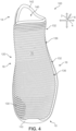
- FIGS. 1 through 6 illustrate an exemplary embodiment of an article of footwear 100, also referred to simply as article 100.
- article of footwear 100 may include a sole structure 110 and an upper 120.
- article 100 is illustrated as having a general configuration suitable for running, concepts associated with article 100 may also be applied to a variety of other athletic footwear types, including soccer shoes, baseball shoes, basketball shoes, cycling shoes, football shoes, tennis shoes, training shoes, walking shoes, and hiking boots, for example.
- the concepts may also be applied to footwear types that are generally considered to be non-athletic, including dress shoes, loafers, sandals, and work boots. Accordingly, the concepts disclosed with respect to article 100 may be applied to a wide variety of footwear types.
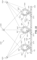
- article 100 may be divided into three general regions: a forefoot region 10, a midfoot region 12, and a heel region 14, as generally shown in FIGS. 1 , 2 , and 3 .
- Forefoot region 10 generally includes portions of article 100 corresponding with the toes and the joints connecting the metatarsals with the phalanges.
- Midfoot region 12 generally includes portions of article 100 corresponding with an arch area of the foot.
- Heel region 14 generally corresponds with rear portions of the foot, including the calcaneus bone.
- Article 100 also includes a lateral side 16 and a medial side 18, which extend through each of forefoot region 10, midfoot region 12, and heel region 14 and correspond with opposite sides of article 100.
- lateral side 16 corresponds with an outside area of the foot (i.e., the surface that faces away from the other foot), and medial side 18 corresponds with an inside area of the foot (i.e., the surface that faces toward the other foot).
- Forefoot region 10, midfoot region 12, and heel region 14 and lateral side 16, medial side 18 are not intended to demarcate precise areas of article 100. Rather, forefoot region 10, midfoot region 12, and heel region 14 and lateral side 16, medial side 18 are intended to represent general areas of article 100 to aid in the following discussion. In addition to article 100, forefoot region 10, midfoot region 12, and heel region 14 and lateral side 16, medial side 18 may also be applied to sole structure 110, upper 120, and individual elements thereof.
- FIG. 4 An exemplary coordinate system for describing the embodiment of article 100 shown in FIGS. 1 through 15 is illustrated in FIG. 4 , where a longitudinal direction 2 extends along article 100 between forefoot region 10 to heel region 14 of article 100, a lateral direction 4 extends along article 100 between lateral side 16 and medial side 18, and a vertical direction 6 extends along article 100 between sole structure 110 and a top of article 100.
- sole structure 110 is secured to upper 120 and extends between the foot and the ground when article 100 is worn.
- sole structure 110 may include one or more components, including a midsole, an outsole, and/or a sockliner or insole.
- sole structure 110 may include an outsole that is secured to a lower surface of upper 120 and/or a base portion configured for securing sole structure 110 to upper 120.
- outsole may be formed from a wear-resistant rubber material that is textured to impart traction.
- sole structure 110 may include a midsole and/or a sockliner.
- a midsole may be secured to a lower surface of an upper and in some cases may be formed from a compressible polymer foam element (e.g., a polyurethane or ethylvinylacetate foam) that attenuates ground reaction forces (i.e., provides cushioning) when compressed between the foot and the ground during walking, running, or other ambulatory activities.
- a midsole may incorporate plates, moderators, fluid-filled chambers, lasting elements, or motion control members that further attenuate forces, enhance stability, or influence the motions of the foot.
- the midsole may be primarily formed from a fluid-filled chamber that is located within an upper and is positioned to extend under a lower surface of the foot to enhance the comfort of an article.
- upper 120 defines a void within article 100 for receiving and securing a foot relative to sole structure 110.
- the void is shaped to accommodate the foot and extends along a lateral side of the foot, along a medial side of the foot, over the foot, around the heel, and under the foot.
- Upper 120 includes an exterior surface 121 and an opposite interior surface 122. Whereas the exterior surface faces outward and away from article 100, the interior surface faces inward and defines a majority or a relatively large portion of the void within article 100 for receiving the foot. Moreover, the interior surface may lay against the foot or a sock covering the foot.
- Upper 120 may also include a collar 142 that is located in at least heel region 14 and forms a throat opening 140.
- throat opening 140 Access to the void is provided by throat opening 140. More particularly, the foot may be inserted into upper 120 through throat opening 140 formed by collar 142, and the foot may be withdrawn from upper 120 through throat opening 140 formed by collar 142.
- an instep area 150 extends forward from collar 142 and throat opening 140 in heel region 14 over an area corresponding to an instep of the foot in midfoot region 12 to an area adjacent to forefoot region 10.
- upper 120 may include a throat portion disposed between lateral side 16 and medial side 18 of upper 120 through instep area 150.
- the throat portion may be integrally attached to and formed of unitary knit construction with portions of upper 120 along lateral and medial sides through instep area 150. Accordingly, as shown in the Figures, upper 120 may extend substantially continuously across instep area 150 between lateral side 16 and medial side 18.
- the throat portion may be disconnected along lateral and medial sides through instep area 150 such that the throat portion is moveable within an opening between a lateral portion and a medial portion on opposite sides of instep area 150, thereby forming a tongue.
- a lace 152 extends through a plurality of lace receiving members 154 in upper 120 and permits the wearer to modify dimensions of upper 120 to accommodate proportions of the foot.
- lace 152 may extend through lace receiving members 154 that are disposed along either side of instep area 150. More particularly, lace 152 permits the wearer to tighten upper 120 around the foot, and lace 152 permits the wearer to loosen upper 120 to facilitate entry and removal of the foot from the void (i.e., through throat opening 140). In addition, the throat portion of upper 120 in instep area 150 extends under lace 152 to enhance the comfort of article 100. Lace 152 is illustrated with article 100 in FIG.
- upper 120 may include additional elements, such as (a) a heel counter in heel region 14 that enhances stability, (b) a toe guard in forefoot region 10 that is formed of a wear-resistant material, and (c) logos, trademarks, and placards with care instructions and material information.
- Knitted component 130 may, for example, be manufactured through a flat knitting process and extends through each of forefoot region 10, midfoot region 12, and heel region 14, along both lateral side 16 and medial side 18, over forefoot region 10, and around heel region 14.
- knitted component 130 forms substantially all of upper 120, including exterior surface 121 and a majority or a relatively large portion of interior surface 122, thereby defining a portion of the void within upper 120.
- knitted component 130 may also extend under the foot. In other embodiments, however, a strobel sock or thin sole-shaped piece of material is secured to knitted component 130 to form an attachment portion of upper 120 that extends under the foot for attachment with sole structure 110.
- a seam 160 extends substantially vertically along lateral side 16 from collar 142 in a downwards direction towards sole structure 110 to join edges of knitted component 130.
- seam 160 may be disposed in a substantially similar manner on medial side 18.
- seam 160 may instead extend vertically through heel region 14 from collar 142 in downwards direction towards sole structure 110 at the rear of article 100.
- knitted component 130 may be formed of unitary knit construction.
- a knitted component e.g., knitted component 130
- knitted component 130 may be joined to each other (e.g., edges of knitted component 130 being joined together) following the knitting process, knitted component 130 remains formed of unitary knit construction because it is formed as a one-piece knit element. Moreover, knitted component 130 remains formed of unitary knit construction when other elements (e.g., a lace, logos, trademarks, placards with care instructions and material information, structural elements) are added following the knitting process.
- elements e.g., a lace, logos, trademarks, placards with care instructions and material information, structural elements
- color-shifting properties refer to the characteristic of an element to appear different colors depending on the viewing angle of the element.
- color-shifting properties may be provided to an article of footwear using a visual effect similar to or inspired by lenticular printing techniques.
- Lenticular printing includes the use of lenses to cause a shift in the visible image or pattern when viewed from different viewing angles. This technique of lenticular printing can be used to create simple animations and visual effects for advertising and other purposes.
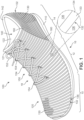
- At least a portion of knitted component 130 includes areas extending between lenticular knit structures 132, i.e., located between the adjacent tubular rib structures forming lenticular knit structures 132, on exterior surface 121 of knitted component.
- a base portion 136 of knitted component 130 is disposed between lenticular knit structures 132.
- base portion 136 can be flexible, elastic, and resilient and assist with stretching of knitted component 130.
- materials forming yarns may be non-fusible or fusible.
- a non-fusible yarn may be substantially formed from a thermoset polyester material and fusible yarn may be at least partially formed from a thermoplastic polyester material.
- fusible yarn is heated and fused to non-fusible yarns, this process may have the effect of stiffening or rigidifying the structure of knitted component 130.
- joining portions of non-fusible yarn using fusible yarns may have the effect of securing or locking the relative positions of non-fusible yarns within knitted component 130, thereby imparting stretch-resistance and stiffness.
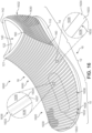
- knitted component 130 includes a plurality of lenticular knit structures 132 in the form of tubular rib structures that extend approximately along the lateral direction between lateral side 16 and medial side 18 through forefoot region 10, midfoot region 12, and a portion of heel region 14.
- Each lenticular knit structure 132 includes first portion 133 disposed on one side of the tubular rib structure facing towards forefoot region 10 at the front of article 100 and second portion 134 disposed on the opposite side of the tubular rib structure facing towards heel region 14 at the back or rear of article 100.
- the color-shifting properties of knitted component 130 caused by lenticular knit structures 132 may vary as article 100 is viewed from different viewing angles.
- the viewing angles from which the color-shifting properties are visible may be different than the viewing angles for the lenticular knit structures 132 disposed approximately along the lateral direction.
- different areas of knitted component 130 and article 100 may have color-shifting properties across various viewing angles, such that as article 100 and/or the viewer move relative to each other, the different areas of knitted component 130 appear to color-shift separately or at different times during movement.
- second type of feeder 722 can deliver a yarn to front needles 703 and/or rear needles 704 for one or more of knitting, tucking, or floating.
- second type of feeder 722 may be a combination feeder that may additionally be configured to inlay a yarn.
- second type of feeder 722 may deliver a tensile element 724 to be inlaid within knitted component 130.
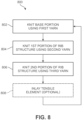
- process 800 may be used to form a plurality of base portions 136 and a plurality of lenticular knit structures 132 disposed throughout a portion or a substantial majority of knitted component 130 to be incorporated into upper 120 for article 100.
- base portions 136 of knitted component 130 may be connecting portions between various elements and/or components of knitted component 130.
- Base portions 136 are formed of unitary knit construction with the remaining portions of knitted component 130 and may serve to connect various portions together as a one-piece knit element.
- Knitted component 130 can include any suitable number of base portions 136.
- base portions 136 can be an area of knitted component 130 comprising one knit layer.
- base portions 136 may extend between one portion of knitted component and another portion of knitted component 130. In one embodiment, base portions 136 can extend between one tubular rib structure and another tubular rib structure forming adjacent lenticular knit structures 132. In a different embodiment, base portions 136 may extend between one tubular rib structure and another portion of knitted component 130. In another embodiment, base portions 136 may extend between one tubular rib structure and an edge of knitted component 130. Suitable configurations of base portions 136 may be in the form of a webbed area described in co-pending and commonly-owned U.S. Patent Application US2016340812 .
- lenticular knit structures 132 may be formed as tubular rib structures that are areas of knitted component 130 constructed with two or more co-extensive and overlapping knit layers.
- Knit layers may be portions of knitted component 130 that are formed by knitted material, for example, threads, yarns, or strands, and two or more knit layers may be formed of unitary knit construction in such a manner so as to form tubes or tunnels, identified as tubular rib structures, in knitted component 130.
- the sides or edges of the knit layers forming the tubular rib structures may be secured to the other layer, a central area is generally unsecured to form a hollow between the two layers of knitted material forming each knit layer.
- Second yarn 903 similarly passes through second feeder 902 and extends outward from a dispensing tip at the end of second feeder 902.
- a third yarn 905 also similarly passes through third feeder 904 and extends outward from a dispensing tip at the end of third feeder 904.
- first yarn 901, second yarn 903, and third yarn 905 may be used to form various portions of knitted component 130, as will be further discussed below.
- Second feeder 902 may similarly make multiple passes to knit the desired number of courses using second yarn 903 to form first portion 133.
- knitting process 800 may proceed to step 806 to knit second portion 134.
- third feeder 904 is used to knit third yarn 905 to form one or more courses forming second portion 134 of the tubular rib structure forming the opposite side of lenticular knit structure 132.
- the optional step 808 of inlaying a tensile element may then be performed to place tensile element 724 within the tubular rib structure.
- base portion 136 can be formed from first yarn 901 using rear needle bed 702, followed by first portion 133 of lenticular knit structure 132 being formed from second yarn 903 and second portion 134 of lenticular knit structure 132 being formed from third yarn 905 using a combination of rear needle bed 702 and front needle bed 701, and another base portion 136 can be formed from first yarn 901 using rear needle bed 702.
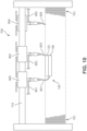
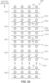
- FIGS. 12-13 The following discussion describes the knitting process schematically illustrated in FIGS. 12-13 , and it will be understood that the front needle bed 701 and rear needle bed 702 referred to in this discussion are shown schematically in FIG. 7 .
- a linking course 1204 may be formed extending between rear needle bed 702 and front needle bed 701.
- one or more courses may be knit on the front needle bed 701 .
- courses forming first portion 133 of lenticular knit structure 132 can be formed in a similar manner as course 1206 knit using second yarn 903 on front needle bed 701 .
- additional courses forming second portion 134 of lenticular knit structure 132 can be formed in a similar manner as course 1210 using third yarn 905 on front needle bed 701.
- third yarn 905 forming second portion 134 of lenticular knit structure 132 can be prepared to be associated with additional courses forming another base portion 136 with first yarn 901 using rear needle bed 702 by transferring knitted component 130 to rear needle bed 702 at step 1216 and repeating the process described above until knitted component 130 is completed.
- different numbers of courses may be knit on one or both of front needle bed 701 and rear needle bed 702 so as to change the shape and/or size of the tubular rib structure forming lenticular knit structure 132.
- the size of the tubular rib structure may be correspondingly enlarged or reduced.
- the shape of the tubular rib structure may be altered.
- the shape of the tubular rib structure may be changed so as to round out the curvature on interior surface 122 of knitted component 130 to be similar to the curvature on exterior surface 121 of knitted component 130.
- the extent or amount of first portion 133 and/or second portion 134 may be similarly modified.
- the color-shifting properties provided to knitted component 130 by a lenticular knit structure with this configuration may be altered so as to increase the number of viewing angles that are associated with the visual effect or color from first portion 133 and/or decreasing the number of viewing angles that are associated with the visual effect or color from second portion 134. That is, a lenticular knit structure having a larger first portion than a second portion will have more viewing angles that are associated with the visual effect caused by the first portion than the second portion, given the greater extent of the second yarn forming the resulting lenticular knit structure.
- lenticular knit structure 132 is formed as a hollow tubular rib structure.
- a tensile element may be inlaid within the unsecured central area of one or more lenticular knit structures 132 forming tubular rib structures.
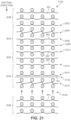
- FIG. 13 illustrates an exemplary knitting diagram 1300 for forming lenticular knit structure 132 including inlaid tensile element 724. As shown in FIG. 13 , the process is substantially similar as the process shown in knitting diagram 1200 for forming lenticular knit structure 132 as a hollow tubular rib structure illustrated in FIG. 12 .
- tensile element 724 is inlaid within a portion of the tubular rib structure forming lenticular knit structure 132 at an inlaying step 1302.
- Tensile element 724 may be inlaid at step 1302 using a combination feeder and associated method of inlaying described in described in U.S. Patent Number 8,522,577 .
- knitting diagram 1300 proceeds in a substantially similar manner as in knitting diagram 1200. That is, another linking course 1214 may be formed extending between rear needle bed 702 and front needle bed 701 that is interlooped to the previous courses on the front needle bed 701 and rear needle bed 702.
- third yarn 905 forming second portion 134 of lenticular knit structure 132 can be prepared to be associated with additional courses forming another base portion 136 with first yarn 901 using rear needle bed 702 by transferring knitted component 130 to rear needle bed 702 at step 1216 and repeating the process described above until knitted component 130 is completed.
- lenticular knit structure 132 including an inlaid tensile element 724 is formed with tensile element 724 being contained within the hollow unsecured area within the tubular rib structure extending along the length of lenticular knit structure 132.
- the formation of knitted component 130 may be similar but entail a switch in the needle beds used.
- the knitting process shown in FIGS. 12 and 13 may be performed using opposite needle beds, such that base portion 136 can be formed using front needle bed 701 and the remaining steps shown in FIGS. 12 and 13 can be performed in identical order using the opposite needle bed than illustrated.
- Other methods of using the various needle beds of knitting machine 700 to form base portion 136 and lenticular knit structure 132, including first portion 133 and second portion 134, will be apparent to one of ordinary skill in the art based on the above description.
- FIGS. 14 and 15 illustrate representational views of a cross section of knitted component 130 incorporating lenticular knit structures 132.
- FIG. 14 illustrates representational view 1400 of a portion of knitted component 130 incorporating lenticular knit structures 132 with hollow unsecured areas 1410.
- each lenticular knit structure 132 includes first portion 133 formed using second yarn 903 and second portion 134 formed using third yarn 905.
- at least one course of first portion 133 formed with second yarn 903 is interlooped with at least one course of second portion 134 formed with third yarn 905.
- first portion 133 and second portion 134 are formed of unitary knit construction.
- Base portion 136 Spaced between and separating each of lenticular knit structures 132 are base portion 136 of knitted component 130.
- Base portion 136 is formed from first yarn 901, as described above, and is also formed of unitary knit construction with first portion 133 and second portion 134 on respective sides of lenticular knit structure 132.
- second yarn 903 and third yarn 905 may be different types that provide different visual effects.
- second yarn 903 may be associated with a first color and third yarn 905 may be associated with a second color that is different from the first.
- second yarn 903 and third yarn 905 may be of types having different characteristics that may cause a visual color-shifting effect.
- first portion 133 formed by second yarn 903 is primarily and substantially presented towards the viewer.
- first portion 133 of lenticular knit structure 132 may provide the primary overall visual effect of knitted component 130 to the viewer.
- the characteristics associated with second yarn 903 forming first portion 133 provide the visual effect, for example, the color of second yarn 903.
- knitted component 130 when knitted component 130 is viewed from a second viewing angle 1404 that is different from first viewing angle 1402, the viewer is presented with a different visual effect.
- second portion 134 formed by third yarn 905 when knitted component 130 is viewed from second viewing angle 1404, second portion 134 formed by third yarn 905 is primarily and substantially presented towards the viewer.
- second portion 134 of lenticular knit structure 132 may provide the primary overall visual appearance of knitted component 130 to the viewer.
- the characteristics associated with third yarn 905 forming second portion 134 provide the visual effect, for example, the color of third yarn 905 that is different from the color of second yarn 903.
- the varying visual effect provided between second yarn 903 and third yarn 905 may include other characteristics, including, but not limited to yarn type, denier, texture, or other properties that generate differing visual effects.
- base portion 136 may be formed using first yarn 901 that is similar or different to either or both of second yarn 903 and third yarn 905 to coordinate or contrast with first portion 133 and/or second portion 134 of lenticular knit structure 132 to further assist with the visual effect provided to knitted component 130.
- each of lenticular knit structures 132 includes an inlaid tensile element 724 extending through unsecured area 1410 within the interior of the tubular rib structure forming lenticular knit structure 132.
- each lenticular knit structure 132 includes an accompanying tensile element 724.
- tensile elements 724 may be disposed in only selected lenticular knit structures 132 located in specific areas or regions of knitted component 130. For example, as shown in FIG.
- tensile elements 724 may be included in lenticular knit structures 132 located along instep area 150 so as to provide lace receiving members 154 that forms loops to receive lace 152. In still other embodiments, tensile elements 724 may be omitted.
- knitted component 130 illustrated lenticular knit structures 132 having two portions formed using different yarns to provide the color-shifting properties to upper 120 and article 100.
- a lenticular knit structure may be formed that includes additional portions formed using another type of yarn different from both of the yarns forming the first and second portions of the lenticular knit structure.
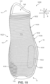
- FIGS. 16 through 22 illustrate an exemplary embodiment of an article of footwear 1600 that includes lenticular knit structures having three portions formed using different yarns.
- FIG. 19 An exemplary coordinate system for describing the exemplary embodiment of article 1600 shown in FIGS. 16 through 22 is illustrated in FIG. 19 , where a longitudinal direction 2 extends along article 1600 between forefoot region 10 to heel region 14 of article 1600, a lateral direction 4 extends along article 1600 between lateral side 16 and medial side 18, and a vertical direction 6 extends along article 1600 between sole structure 110 and a top of article 1600.
- article 1600 includes an upper 1620 that includes components that are substantially similar to the components associated with upper 120, described above.
- upper 1620 may include throat opening 140 surrounded by collar 142, and may be joined along seam 160, as described above.
- upper 1620 may include exterior surface 121 and interior surface 122 associated with, respectively, the outside and inside of article 1600.
- Upper 1620 may be joined or secured to sole structure 110 to complete article of footwear 1600.
- upper 1620 incorporates a knitted component 1630 that includes first lenticular knit structures 1632 having two portions formed from two different yarns, in a substantially similar manner as, and substantially similar to, lenticular knit structures 132, described above.
- knitted component 1630 further includes at least one area 1602 with second lenticular knit structures 1638 having three portions formed from three different yarns.
- knitted component 1630 includes base portions 1636 that are disposed between one or more of first lenticular knit structures 1632 and/or second lenticular knit structures 1638.
- base portions 1636 may be formed in a substantially similar manner as, and substantially similar to, base portions 136, described above.
- knitted component 1630 includes area 1602 having one or more second lenticular knit structures 1638, while the remaining portion of knitted component 1630 includes first lenticular knit structures 1632. While this embodiment illustrates a single area 1602 having second lenticular knit structures 1638, it should be understood that additional or different areas located on other areas or portions of knitted component 1630 may be provided. Additionally, in some embodiments, area 1602 may be selected so as to serve as an indicia, logo, pattern, or other visual effect that is different from the remaining portions of knitted component 1630.
- first lenticular knit structures 1632 may provide color-shifting properties to knitted component 1630 through incorporation of two or more types of yarn being used to knit first lenticular knit structure 1632.
- first lenticular knit structure 1632 is in the form of a tubular rib structure
- different portions of first lenticular knit structure 1632 may include different types of yarn along each side of the tubular rib structure.
- a first portion 1633 of first lenticular knit structure 1632 disposed on one side of the tubular rib structure may be knit using a first yarn and a second portion 1634 of first lenticular knit structure 1632 disposed on the opposite side of the tubular rib structure may be knit using a second yarn that is different from the first yarn.
- the types of yarn may vary in color to provide the color-shifting properties to knitted component 1630. In other cases, the types of yarn may vary in texture or denier to provide the color-shifting properties to knitted component 1630.
- knitted component 1630 further includes area 1602 with second lenticular knit structures 1638.
- Second lenticular knit structures 1638 may similarly provide color-shifting properties to knitted component 1630 through incorporation of two or more types of yarn being used to knit the lenticular knit structure 1638, as with first lenticular knit structure 1632.
- second lenticular knit structure 1638 is in the form of a tubular rib structure
- different portions of second lenticular knit structure 1638 may similarly include different types of yarn along each side of the tubular rib structure, including first portion 1633 of second lenticular knit structure 1638 disposed on one side of the tubular rib structure knit using the first yarn and second portion 1634 of second lenticular knit structure 1638 disposed on the opposite side of the tubular rib structure may be knit using the second yarn that is different from the first yarn.
- second tubular knit structure 1638 further includes an upper portion 1637 disposed on the top of the tubular rib structure using a third yarn that is different from both the first yarn and the second yarn used for each of first portion 1633 and second portion 1634.
- second lenticular knit structure 1638 may present a third visual effect caused by upper portion 1637 to knitted component 1630 that is different from the visual effects presented by first portion 1633 and/or second portion 1634 disposed along the sides of second lenticular knit structures 1638 and first lenticular knit structures 1632.
- area 1602 having second lenticular knit structures 1638 may be located approximately in a portion of forefoot region 10 and/or midfoot region 12 and be offset towards lateral side 16 of article 1600.
- area 1602 may present the third visual effect to a viewer when article 1600 and upper 1620 are viewed from a viewing angle that includes at least a portion of lateral side 16, while area 1602 may not present the third visual effect to a viewer when article 1600 and upper 1620 are viewed from a viewing angle that is primarily along medial side 18.
- medial side view illustrated in FIG. 17 area 1602 is not visible from medial side 18.
- lateral side view illustrated in FIG. 18 area 1602 is visible from lateral side 16.
- area 1602 is also visible to the viewer.
- area 1602 including second lenticular knit structures 1638 may be selectively provided on various portions of knitted component 1630. In different embodiments, however, area 1602 or additional areas, may be located on different portions of upper 1620 as desired to produced different color-shifting properties to those portions of upper 1620.
- first lenticular knit structure 1632 may be formed in a substantially similar manner as lenticular knit structure 132, described above and shown in particular with reference to knitting diagrams 1200 and 1300 in FIGS. 12 and 13 .
- the knitting process for knitting second lenticular knit structure 1638 may include many similar steps as first lenticular knit structure 1632 and/or lenticular knit structure 132.
- a third yarn may be used to form upper portion 1637 of second lenticular knit structure 1638 so as to present the third visual effect to knitted component 1630.
- FIGS. 20 and 21 illustrate exemplary knitting or looping diagrams of the sequencing of knitting each of the portions of knitted component 1630, including base portion 1636, first portion 1633, second portion 1634, and upper portion 1637, with respect to the specific needle beds that may be used to form each portion. It should be noted, however, that FIGS. 20 and 21 illustrate one exemplary configuration of implementing a knitting process for forming knitted component 1630. Other configurations may be readily obtained according to the principles of the invention described herein to form other lenticular knit structures to provide color-shifting properties to an article.
- base portion 1636 can be formed from first yarn 901 using rear needle bed 702, followed by first portion 1633 of second lenticular knit structure 1638 being formed from second yarn 903 and second portion 1634 of second lenticular knit structure 1638 being formed from third yarn 905 using a combination of rear needle bed 702 and front needle bed 701, and another base portion 1636 can be formed from first yarn 901 using rear needle bed 702.
- FIGS. 20-21 The following discussion describes the knitting process schematically illustrated in FIGS. 20-21 , and it will be understood that the front needle bed 701 and rear needle bed 702 referred to in this discussion are shown schematically in FIG. 7 .
- a linking course 2004 may be formed extending between rear needle bed 702 and front needle bed 701.
- one or more courses may be knit on the front needle bed 701 .
- courses forming first portion 1633 of second lenticular knit structure 1638 can be formed in a similar manner as course 2006 knit using second yarn 903 on front needle bed 701 .
- courses forming upper portion 1637 of second lenticular knit structure 1638 can be formed in a similar manner as course 2010 using fourth yarn 907.
- additional courses forming second portion 1634 of second lenticular knit structure 1638 can be formed in a similar manner as course 2012 using third yarn 905 on front needle bed 701 .
- third yarn 905 may be used to knit a course 2014 with rear needle bed 702.
- course 2014 may form the last course of second portion 1634 of second lenticular knit structure 1638 that closes the tubular rib structure and forms a hollow tunnel.
- another linking course 2016 may be formed extending between rear needle bed 702 and front needle bed 701 that is interlooped to the previous courses on the front needle bed 701 and rear needle bed 702.
- third yarn 905 forming second portion 1634 of second lenticular knit structure 1638 can be prepared to be associated with additional courses forming another base portion 1636 with first yarn 901 using rear needle bed 702 by transferring knitted component 1630 to rear needle bed 702 at step 2018 and repeating the process described above until knitted component 1630 is completed.
- different numbers of courses may be knit on one or both of front needle bed 701 and rear needle bed 702 so as to change the shape and/or size of the tubular rib structure forming second lenticular knit structure 1638, as described above with regard to lenticular knit structure 132.
- second lenticular knit structure 1638 is formed as a hollow tubular rib structure.
- a tensile element may be inlaid within the unsecured central area of one or more second lenticular knit structures 1638 forming tubular rib structures, in a similar manner as first lenticular knit structures 1632 and/or lenticular knit structures 132.
- FIG. 21 illustrates an exemplary knitting diagram 2100 for forming second lenticular knit structure 1638 including inlaid tensile element 724. As shown in FIG. 21 , the process is substantially similar as the process shown in knitting diagram 2000 for forming second lenticular knit structure 1638 as a hollow tubular rib structure illustrated in FIG. 20 .
- tensile element 724 is inlaid within a portion of the tubular rib structure forming second lenticular knit structure 1638 at an inlaying step 2102.
- Tensile element 724 may be inlaid at step 2102 using a combination feeder and associated method of inlaying described in described in U.S. Patent Number 8,522,577 to Huffa , incorporated by reference above.
- knitting diagram 2100 proceeds in a substantially similar manner as in knitting diagram 2000. That is, another linking course 2016 may be formed extending between rear needle bed 702 and front needle bed 701 that is interlooped to the previous courses on the front needle bed 701 and rear needle bed 702.
- third yarn 905 forming second portion 1634 of second lenticular knit structure 1638 can be prepared to be associated with additional courses forming another base portion 1636 with first yarn 901 using rear needle bed 702 by transferring knitted component 1630 to rear needle bed 702 at step 2018 and repeating the process described above until knitted component 1630 is completed.
- second lenticular knit structure 1638 including an inlaid tensile element 724 is formed with tensile element 724 being contained within the hollow unsecured area within the tubular rib structure extending along the length of second lenticular knit structure 1638.
- FIG. 22 illustrates a representational view 2200 of a cross section of a portion of knitted component 1630 incorporating second lenticular knit structures 1638.
- view 2200 may be a portion of knitted component associated with area 1602.
- the portion of knitted component 1630 incorporates second lenticular knit structures 1638 with hollow unsecured areas 2210.
- second lenticular knit structures 1638 including inlaid tensile elements 724 may have a substantially similar structure with inlaid tensile element 724 being located with hollow unsecured areas 2210.
- each second lenticular knit structure 1638 includes first portion 1633 formed using second yarn 903 and second portion 1634 formed using third yarn 905.
- second lenticular knit structure 1638 further includes upper portion 1637 formed using fourth yarn 907.
- upper portion 1637 is located at the top of the tubular rib structure forming second lenticular knit structure 1638.
- upper portion 1637 formed using fourth yarn 907 may be disposed between first portion 1633 and second portion 1634. That is, at least one course of first portion 1633 formed with second yarn 903 is interlooped with at least one course of upper portion 1637 formed with fourth yarn 907 and at least one course of second portion 1634 formed with third yarn 905 is also interlooped with at least one course of upper portion 1637 formed with fourth yarn 907. With this configuration, each of first portion 1633, upper portion 1637, and second portion 1634 are formed of unitary knit construction.
- Base portion 1636 Spaced between and separating each of second lenticular knit structures 1638 are base portion 1636 of knitted component 1630.
- Base portion 1636 is formed from first yarn 901, as described above, and is also formed of unitary knit construction with first portion 1633 and second portion 1634 on respective sides of second lenticular knit structure 1638.
- second lenticular knit structure 1638 including first portion 1633 formed by second yarn 903 on one side of the tubular rib structure and second portion 1634 formed by third yarn 905 on the opposite side of the tubular rib structure provides the color-shifting properties to knitted component 1630.
- upper portion 1637 of second lenticular knit structure 1638 formed by fourth yarn 907 on the top of the tubular rib structure may provide an additional visual effect to knitted component 1630.
- second yarn 903 and third yarn 905 may be different types that provide different visual effects.
- second yarn 903 may be associated with a first color and third yarn 905 may be associated with a second color that is different from the first.
- second yarn 903 and third yarn 905 may be of types having different characteristics that may cause a visual color-shifting effect.
- fourth yarn 907 may be a different type from either or both of second yarn 903 and third yarn 905.
- first portion 1633 formed by second yarn 903 is primarily and substantially presented towards the viewer.
- first portion 1633 of second lenticular knit structure 1638 may provide the primary overall visual effect of knitted component 1630 to the viewer.
- the characteristics associated with second yarn 903 forming first portion 1633 provide the visual effect, for example, the color of second yarn 903.
- second portion 1634 formed by third yarn 905 is primarily and substantially presented towards the viewer.
- second portion 1634 of second lenticular knit structure 1638 may provide the primary overall visual appearance of knitted component 1630 to the viewer.
- the characteristics associated with third yarn 905 forming second portion 1634 provide the visual effect, for example, the color of third yarn 905 that is different from the color of second yarn 903.
- the varying visual effect provided between second yarn 903 and third yarn 905 may include other characteristics, including, but not limited to yarn type, denier, texture, or other properties that generate differing visual effects.
- second lenticular knit structures 1638 on knitted component 1630 as well as the similar components forming first lenticular knit structures 1632, the color-shifting properties of upper 1620 and/or article 1600 may be provided so that a viewer observes a change in the visual effect of upper 1620 and/or article 1600 as the viewing angle changes, for example, as the viewing angle changes between first viewing angle 2202 and second viewing angle 2204.
- second lenticular knit structures 1638 are configured to provide a third visual effect caused by upper portion 1637 formed using fourth yarn 907.
- the third visual effect generated by upper portion 1637 of second lenticular knit structures 1638 may be visible when viewing knitted component 1630 from a third viewing angle 2206 that is viewing the tops of second lenticular knit structures 1638 from an approximately vertical direction.
- upper portion 1637 is also visible when viewing knitted component 1630 from either or both of first viewing angle 2202 and second viewing angle 2204. That is, the third visual effect provided by upper portion 1637 formed using fourth yarn 907 may remain substantially constant across multiple viewing angles.
- the same visual effect generated by upper portion 1637 is visible from first viewing angle 2202, second viewing angle 2204, and third viewing angle 2206.
- second lenticular knit structure 1638 may provide a visual effect within area 1602 of knitted component 1630 that remains substantially unchanged through multiple viewing angles.
- base portion 1636 may be formed using first yarn 901 that is similar or different to one or more of second yarn 903, third yarn 905, and/or fourth yarn 907 to coordinate or contrast with first portion 1633, upper portion 1637, and/or second portion 1634 of second lenticular knit structure 1638 to further assist with the visual effects provided to knitted component 1630.
- an article of footwear including an upper and a sole structure attached to the upper.
- the upper can incorporate a knitted component formed of unitary knit construction.
- the knitted component comprises at least one lenticular knit structure including a first portion and a second portion disposed on opposite sides of the lenticular knit structure.
- the knitted component comprises a base portion disposed adjacent to the at least one lenticular knit structure.
- the at least one lenticular knit structure extends away from the base portion on an exterior surface of the upper.
- the first portion of the at least one lenticular knit structure is associated with a first visual effect when the upper is viewed from a first viewing angle and the second portion of the at least one lenticular knit structure is associated with a second visual effect when the upper is viewed from a second viewing angle that is different than the first viewing angle.
- the first portion of the at least one lenticular knit structure is formed using a first yarn and the second portion of the at least one lenticular knit structure is formed using a second yarn.
- the first yarn and the second yarn have different characteristics.
- the first yarn and the second yarn are one or more of different yarn types, different colors, different textures, and different deniers.
- the first yarn can substantially generate the first visual effect when the upper is viewed from the first viewing angle and the second yarn can substantially generate the second visual effect when the upper is viewed from the second viewing angle.
- the knitted component comprises a plurality of lenticular knit structures.
- the plurality of lenticular knit structures comprises a first lenticular knit structure and a second lenticular knit structure.
- the first lenticular knit structure may have the first portion formed using a first yarn and the second portion formed using a second yarn.
- the second lenticular knit structure may have the first portion formed using the first yarn, the second portion formed using the second yarn.
- One or more of the second lenticular knit structures can be located in a first area on the knitted component.
- the remaining portion of the knitted component can includes a plurality of the first lenticular knit structures.
- the first yarn, the second yarn, and the third yarn can be different colors.
- the upper portion can generate a third visual effect that is visible from both the first viewing angle and the second viewing angle.
- Theknitted component is provided for incorporating into an article.
- the knitted component comprises a plurality of lenticular knit structures.
- Each of the lenticular knit structures includes a first portion formed using a first yarn on one side of the lenticular knit structure and a second portion formed using a second yarn disposed on an opposite side of the lenticular knit structure.
- the first yarn and the second yarn are different.
- a base portion is disposed between adjacent lenticular knit structures.
- the first portion, the second portion, and the base portion can be formed of unitary knit construction with the knitted component.
- the first portion of the lenticular knit structure is associated with a first visual effect when the knitted component is viewed from a first viewing angle and the second portion of the at least one lenticular knit structure is associated with a second visual effect when the knitted component is viewed from a second viewing angle that is different than the first viewing angle.
- the base portion can be formed using a yarn that is different from the first yarn and the second yarn.
- the base portion can include at least one course that is connected to: (a) at least one course of the first yarn forming the first portion, and (b) at least one course of the second yarn forming the second portion.
- Each of the plurality of lenticular knit structures can have the configuration of a tubular rib structure, including a hollow unsecured area disposed between overlapping knit layers of the tubular rib structure.
- At least one of the plurality of lenticular knit structures can include a tensile element disposed within the hollow unsecured area.
- the plurality of lenticular knit structures comprises a first lenticular knit structure and a second lenticular knit structure.
- the first lenticular knit structure has the first portion formed using the first yarn and the second portion formed using the second yarn.
- the second lenticular knit structure has the first portion formed using the first yarn, the second portion formed using the second yarn.
- An upper portion can be disposed between the first portion and the second portion. The upper portion can be formed using a third yarn.
- the upper portion can generate a third visual effect that is visible from both the first viewing angle and the second viewing angle.
- a method of manufacturing a knitted component for incorporating into an article is provided.
- the method comprises: knitting a base portion of the knitted component, knitting a first portion of a lenticular knit structure using a first yarn, knitting a second portion of the lenticular knit structure using a second yarn.
- the second yarn is different from the first yarn.
- the lenticular knit structure is formed so that the first portion and the second portion are disposed on opposite sides of the lenticular knit structure and the lenticular knit structure extends away from the base portion in a vertical direction.
- the first portion of the lenticular knit structure is associated with a first visual effect when the knitted component is viewed from a first viewing angle and the second portion of the at least one lenticular knit structure is associated with a second visual effect when the knitted component is viewed from a second viewing angle that is different than the first viewing angle.
- the base portion, the first portion, and the second portion can be formed of unitary knit construction during a knitting process.
- the method further comprises: knitting an upper portion of the lenticular knit structure disposed between the first portion and the second portion.
- the upper portion can be knit using a third yarn.
- the upper portion can generate a third visual effect that is visible from both the first viewing angle and the second viewing angle.
- the method may also comprise: inlaying a tensile element within the lenticular knit structure.
- the above aspects generally assist in decreasing the number of material elements used in the upper, therefore, waste may be decreased while increasing the manufacturing efficiency and recyclability of the upper.
- an article comprising at least one lenticular structure.
- the article comprises a base portion disposed adjacent to the at least one lenticular structure comprising at least one yarn and including a first portion and a second portion.
- the at least one lenticular structure extends away from the base portion on an exterior surface of the article.
- the first portion of the at least one lenticular structure is associated with a first visual effect when the article is viewed from a first viewing angle and the second portion of the at least one lenticular structure is associated with a second visual effect when the article is viewed from a second viewing angle that is different than the first viewing angle.
- the article can include an upper and a sole structure attached to the upper, the upper comprising the at least one lenticular structure.
- the lenticular structure comprises a knitted structure.
- the upper can be formed of unitary knit construction.
- the first portion of the at least one lenticular structure is formed using the first yarn and the second portion of the at least one lenticular structure is formed using a second yarn, the first yarn and the second yarn having different characteristics.
- an article comprising at least one lenticular knit structure.
- the article comprises a base portion disposed adjacent to the at least one lenticular knit structure comprising at least one yarn and including a first portion and a second portion.
- the at least one lenticular knit structure extends away from the base portion on an exterior surface of the article.
- the first portion of the at least one lenticular knit structure is associated with a first visual effect when the article is viewed from a first viewing angle and the second portion of the at least one lenticular knit structure is associated with a second visual effect when the article is viewed from a second viewing angle that is different than the first viewing angle.
- the article can include an upper and a sole structure attached to the upper, the upper comprising the at least one lenticular knit structure.
- the upper can be formed of unitary knit construction.
- the first portion of the at least one lenticular knit structure is formed using the first yarn and the second portion of the at least one lenticular knit structure is formed using a second yarn, the first yarn and the second yarn having different characteristics.
- the first yarn and the second yarn are of one or more of different yarn types, different colors, different textures, and different deniers.
Landscapes
- Engineering & Computer Science (AREA)
- Textile Engineering (AREA)
- Chemical & Material Sciences (AREA)
- Materials Engineering (AREA)
- Knitting Of Fabric (AREA)
- Footwear And Its Accessory, Manufacturing Method And Apparatuses (AREA)
- Purses, Travelling Bags, Baskets, Or Suitcases (AREA)
- Bedding Items (AREA)
Claims (14)
- Strickkomponente (130) zum Einarbeiten in einen Fußbekleidungsartikel (100), wobei die Strickkomponente (130) Folgendes umfasst:mehrere linsenförmige Strickstrukturen (132), wobei jede der linsenförmigen Strickstrukturen (132) einen ersten Abschnitt (133), der unter Verwendung eines ersten Garns auf einer Seite der linsenförmigen Strickstruktur (132) gebildet ist, und einen zweiten Abschnitt (134) aufweist, der unter Verwendung eines zweiten Garns gebildet und auf einer entgegengesetzten Seite der linsenförmigen Strickstruktur (132) angeordnet ist, wobei das erste Garn und das zweite Garn unterschiedlich sind, undeinen Basisabschnitt (136), wobei sich die linsenförmige Strickstruktur (132) in einer vertikalen Richtung (6) von dem Basisabschnitt (136) wegerstreckt, undwobei der erste Abschnitt (133) der linsenförmigen Strickstruktur (132) einer ersten optischen Wirkung zugeordnet ist, wenn die Strickkomponente (130) aus einem ersten Betrachtungswinkel (500) betrachtet wird, und der zweite Abschnitt (134) der wenigstens einen linsenförmigen Strickstruktur (132) einer zweiten optischen Wirkung zugeordnet ist, wenn die Strickkomponente (130) aus einem zweiten Betrachtungswinkel (600) betrachtet wird, der von dem ersten Betrachtungswinkel (500) verschieden ist,dadurch gekennzeichnet, dass der Basisabschnitt (136) zwischen benachbarten linsenförmigen Strickstrukturen (132) angeordnet ist und dass die Strickkomponente (130) so ausgebildet ist, dass der Basisabschnitt (136) beim Dehnen der Strickkomponente (130) zwischen den benachbarten linsenförmigen Strickstrukturen (132) freilegbar ist.
- Strickkomponente (130) nach Anspruch 1, bei der der erste Abschnitt (133), der zweite Abschnitt (134) und der Basisabschnitt (136) aus einheitlichem Strickaufbau mit der Strickkomponente (130) gebildet sind.
- Strickkomponente (130) nach Anspruch 1 oder 2, bei der der Basisabschnitt (136) unter Verwendung eines Garns gebildet ist, das von dem ersten Garn und dem zweiten Garn verschieden ist, und
wobei der Basisabschnitt (136) wenigstens eine Maschenreihe aufweist, die verbunden ist mit: a) wenigstens einer Maschenreihe des ersten Garns, das den ersten Abschnitt (133) bildet, und b) wenigstens einer Maschenreihe des zweiten Garns, das den zweiten Abschnitt (134) bildet. - Strickkomponente (130) nach einem der vorhergehenden Ansprüche, bei der jede der mehreren linsenförmigen Strickstrukturen (132) die Gestaltung einer röhrenförmigen Rippenstruktur hat, die einen hohlen, unbefestigten Bereich aufweist, der zwischen überlappenden Stricklagen der röhrenförmigen Rippenstruktur angeordnet ist.
- Strickkomponente (130) nach Anspruch 4, bei der wenigstens eine der mehreren linsenförmigen Strickstrukturen (132) ferner ein dehnbares Element (724) aufweist, das in dem hohlen, unbefestigten Bereich angeordnet ist.
- Strickkomponente (130) nach einem der vorhergehenden Ansprüche, bei der die mehreren linsenförmigen Strickstrukturen (132) eine erste linsenförmige Strickstruktur (132) und eine zweite linsenförmige Strickstruktur (132) umfassen, wobei die erste linsenförmige Strickstruktur (132) den ersten Abschnitt (133), der unter Verwendung des ersten Garns gebildet ist, und den zweiten Abschnitt (134) aufweist, der unter Verwendung des zweiten Garns gebildet ist, und die zweite linsenförmige Strickstruktur (132) den ersten Abschnitt (133), der unter Verwendung des ersten Garns gebildet ist, den zweiten Abschnitt (134), der unter Verwendung des zweiten Garns gebildet ist, und einen oberen Abschnitt (1637) aufweist, der zwischen dem ersten Abschnitt (133) und dem zweiten Abschnitt (134) angeordnet ist, wobei der obere Abschnitt (1637) unter Verwendung eines dritten Garns gebildet ist.
- Strickkomponente (130) nach Anspruch 6, bei der der obere Abschnitt (1637) eine dritte optische Wirkung erzeugt, die sowohl aus dem ersten Betrachtungswinkel (500) als auch aus dem zweiten Betrachtungswinkel (600) sichtbar ist.
- Verfahren zur Herstellung einer Strickkomponente (130) zum Einarbeiten in einen Fußbekleidungsartikel, wobei das Verfahren Folgendes umfasst:Stricken eines Basisabschnitts (136) der Strickkomponente (130),Stricken eines ersten Abschnitts (133) einer linsenförmigen Strickstruktur (132) unter Verwendung eines ersten Garns,Stricken eines zweiten Abschnitts (134) der linsenförmigen Strickstruktur (132) unter Verwendung eines zweiten Garns, wobei das zweite Garn von dem ersten Garn verschieden ist,wobei die linsenförmige Strickstruktur (132) so gebildet wird, dass der erste Abschnitt (133) und der zweite Abschnitt (134) auf entgegengesetzten Seiten der linsenförmigen Strickstruktur (132) angeordnet sind und die linsenförmige Strickstruktur (132) sich in einer vertikalen Richtung (6) von dem Basisabschnitt (136) weg erstreckt, undwobei der erste Abschnitt (133) der linsenförmigen Strickstruktur (132) einer ersten optischen Wirkung zugeordnet ist, wenn die Strickkomponente (130) aus einem ersten Betrachtungswinkel (500) betrachtet wird, und der zweite Abschnitt (134) der wenigstens einen linsenförmigen Strickstruktur (132) einer zweiten optischen Wirkung zugeordnet ist, wenn die Strickkomponente (130) aus einem zweiten Betrachtungswinkel (600) betrachtet wird, der von dem ersten Betrachtungswinkel (500) verschieden ist,dadurch gekennzeichnet, dass der Basisabschnitt (136) zwischen benachbarten linsenförmigen Strickstrukturen (132) angeordnet ist, und wobei die Strickkomponente (130) so ausgebildet ist, dass der Basisabschnitt (136) beim Dehnen der Strickkomponente (130) zwischen den benachbarten linsenförmigen Strickstrukturen (132) freilegbar ist.
- Verfahren nach Anspruch 8, bei dem der Basisabschnitt (136), der erste Abschnitt (133) und der zweite Abschnitt (134) während eines Strickvorgangs aus einem einheitlichen Strickaufbau gebildet werden.
- Verfahren nach Anspruch 8 oder 9, wobei das Verfahren ferner das Stricken eines oberen Abschnitts (1637) der linsenförmigen Strickstruktur (132) umfasst, der zwischen dem ersten Abschnitt (133) und dem zweiten Abschnitt (134) angeordnet ist, wobei der obere Abschnitt unter Verwendung eines dritten Garns gestrickt wird.
- Verfahren nach Anspruch 10, bei dem der obere Abschnitt (1637) eine dritte optische Wirkung erzeugt, die sowohl aus dem ersten Betrachtungswinkel (500) als auch aus dem zweiten Betrachtungswinkel (600) sichtbar ist.
- Verfahren nach einem der Ansprüche 8 bis 11, bei dem ferner ein dehnbares Element (724) in die linsenförmige Strickstruktur (132) eingelegt wird.
- Fußbekleidungsartikel (100) mit:
einer Strickkomponente (130) nach Anspruch 1. - Artikel nach Anspruch 13, wobei der Artikel ein Oberteil (120) und eine an dem Oberteil (120) befestigte Sohlenstruktur (110) aufweist und wobei das Oberteil (120) die wenigstens eine linsenförmige Strickstruktur (132) umfasst.
Priority Applications (1)
| Application Number | Priority Date | Filing Date | Title |
|---|---|---|---|
| EP25167608.6A EP4596771A3 (de) | 2014-09-30 | 2015-09-25 | Gestrickteil mit röhrenförmigen gestrickstrukturen und sein herstellungsverfahren |
Applications Claiming Priority (6)
| Application Number | Priority Date | Filing Date | Title |
|---|---|---|---|
| US201462057293P | 2014-09-30 | 2014-09-30 | |
| US201462057264P | 2014-09-30 | 2014-09-30 | |
| US14/535,413 US9375046B2 (en) | 2014-09-30 | 2014-11-07 | Article of footwear incorporating a knitted component with inlaid tensile elements and method of assembly |
| US14/535,448 US9078488B1 (en) | 2014-09-30 | 2014-11-07 | Article of footwear incorporating a lenticular knit structure |
| PCT/US2015/052426 WO2016053805A1 (en) | 2014-09-30 | 2015-09-25 | Knitted component for an article incorporating a lenticular knit structure and method of making same |
| EP15782125.7A EP3201379B1 (de) | 2014-09-30 | 2015-09-25 | Schuhartikel mit einem gestrickteil für ein schuhoberteil mit einer röhrenförmigen gestrickstruktur und sein herstellungsverfahren |
Related Parent Applications (1)
| Application Number | Title | Priority Date | Filing Date |
|---|---|---|---|
| EP15782125.7A Division EP3201379B1 (de) | 2014-09-30 | 2015-09-25 | Schuhartikel mit einem gestrickteil für ein schuhoberteil mit einer röhrenförmigen gestrickstruktur und sein herstellungsverfahren |
Related Child Applications (1)
| Application Number | Title | Priority Date | Filing Date |
|---|---|---|---|
| EP25167608.6A Division EP4596771A3 (de) | 2014-09-30 | 2015-09-25 | Gestrickteil mit röhrenförmigen gestrickstrukturen und sein herstellungsverfahren |
Publications (3)
| Publication Number | Publication Date |
|---|---|
| EP4234783A2 EP4234783A2 (de) | 2023-08-30 |
| EP4234783A3 EP4234783A3 (de) | 2023-10-25 |
| EP4234783B1 true EP4234783B1 (de) | 2025-04-02 |
Family
ID=53506602
Family Applications (3)
| Application Number | Title | Priority Date | Filing Date |
|---|---|---|---|
| EP23175653.7A Active EP4234783B1 (de) | 2014-09-30 | 2015-09-25 | Gestrickteil mit röhrenförmigen gestrickstrukturen und sein herstellungsverfahren |
| EP25167608.6A Pending EP4596771A3 (de) | 2014-09-30 | 2015-09-25 | Gestrickteil mit röhrenförmigen gestrickstrukturen und sein herstellungsverfahren |
| EP15782125.7A Active EP3201379B1 (de) | 2014-09-30 | 2015-09-25 | Schuhartikel mit einem gestrickteil für ein schuhoberteil mit einer röhrenförmigen gestrickstruktur und sein herstellungsverfahren |
Family Applications After (2)
| Application Number | Title | Priority Date | Filing Date |
|---|---|---|---|
| EP25167608.6A Pending EP4596771A3 (de) | 2014-09-30 | 2015-09-25 | Gestrickteil mit röhrenförmigen gestrickstrukturen und sein herstellungsverfahren |
| EP15782125.7A Active EP3201379B1 (de) | 2014-09-30 | 2015-09-25 | Schuhartikel mit einem gestrickteil für ein schuhoberteil mit einer röhrenförmigen gestrickstruktur und sein herstellungsverfahren |
Country Status (7)
| Country | Link |
|---|---|
| US (5) | US9078488B1 (de) |
| EP (3) | EP4234783B1 (de) |
| JP (3) | JP6637036B2 (de) |
| KR (5) | KR102069816B1 (de) |
| MX (2) | MX364138B (de) |
| TW (4) | TWI720346B (de) |
| WO (1) | WO2016053805A1 (de) |
Families Citing this family (75)
| Publication number | Priority date | Publication date | Assignee | Title |
|---|---|---|---|---|
| US7107235B2 (en) | 2000-03-10 | 2006-09-12 | Lyden Robert M | Method of conducting business including making and selling a custom article of footwear |
| US7347011B2 (en) | 2004-03-03 | 2008-03-25 | Nike, Inc. | Article of footwear having a textile upper |
| DE102012206062B4 (de) | 2012-04-13 | 2019-09-12 | Adidas Ag | Schuhoberteil |
| US9861160B2 (en) * | 2012-11-30 | 2018-01-09 | Nike, Inc. | Article of footwear incorporating a knitted component |
| DE102013207163B4 (de) | 2013-04-19 | 2022-09-22 | Adidas Ag | Schuhoberteil |
| US12250994B2 (en) | 2013-04-19 | 2025-03-18 | Adidas Ag | Shoe |
| US11666113B2 (en) | 2013-04-19 | 2023-06-06 | Adidas Ag | Shoe with knitted outer sole |
| DE102013207156B4 (de) | 2013-04-19 | 2025-12-24 | Adidas Ag | Schuh, insbesondere ein Sportschuh |
| DE102013207155B4 (de) | 2013-04-19 | 2020-04-23 | Adidas Ag | Schuhoberteil |
| DE102014202432B4 (de) | 2014-02-11 | 2017-07-27 | Adidas Ag | Verbesserter Fußballschuh |
| US9375046B2 (en) | 2014-09-30 | 2016-06-28 | Nike, Inc. | Article of footwear incorporating a knitted component with inlaid tensile elements and method of assembly |
| US10822728B2 (en) | 2014-09-30 | 2020-11-03 | Nike, Inc. | Knitted components exhibiting color shifting effects |
| US9192204B1 (en) | 2014-09-30 | 2015-11-24 | Nike, Inc. | Article of footwear upper incorporating a textile component with tensile elements |
| US9078488B1 (en) * | 2014-09-30 | 2015-07-14 | Nike, Inc. | Article of footwear incorporating a lenticular knit structure |
| DE102014220087B4 (de) | 2014-10-02 | 2016-05-12 | Adidas Ag | Flachgestricktes Schuhoberteil für Sportschuhe |
| KR102206306B1 (ko) * | 2014-12-18 | 2021-01-21 | 푸마 에스이 | 신발, 특히 운동화 |
| US9820530B2 (en) | 2015-01-16 | 2017-11-21 | Nike, Inc. | Knit article of footwear with customized midsole and customized cleat arrangement |
| US9848673B2 (en) | 2015-01-16 | 2017-12-26 | Nike, Inc. | Vacuum formed knit sole system for an article of footwear incorporating a knitted component |
| US9775401B2 (en) | 2015-01-16 | 2017-10-03 | Nike, Inc. | Sole system for an article of footwear incorporating a knitted component with a one-piece knit outsole |
| US10568383B2 (en) | 2015-01-16 | 2020-02-25 | Nike, Inc. | Sole system for an article of footwear incorporating a knitted component with a one-piece knit outsole and a tensile element |
| HK1247117A1 (zh) * | 2015-03-27 | 2018-09-21 | 免疫生物公司 | 用於治疗癌症的被遗传修饰的nk-92细胞和单克隆抗体 |
| EP3294084A4 (de) * | 2015-05-08 | 2019-01-16 | Under Armour, Inc. | Fussbekleidung mit textilem obermaterial |
| USD792080S1 (en) | 2015-08-17 | 2017-07-18 | Nike, Inc. | Shoe upper |
| USD841969S1 (en) | 2015-08-17 | 2019-03-05 | Nike, Inc. | Shoe upper |
| USD841303S1 (en) | 2015-08-17 | 2019-02-26 | Nike, Inc. | Shoe upper |
| USD785309S1 (en) | 2015-08-17 | 2017-05-02 | Nike, Inc. | Shoe upper |
| USD783981S1 (en) * | 2015-08-17 | 2017-04-18 | Nike, Inc. | Shoe upper |
| USD781552S1 (en) * | 2015-08-17 | 2017-03-21 | Nike, Inc. | Shoe upper |
| JP2018532461A (ja) * | 2015-09-08 | 2018-11-08 | エイヴェリー デニソン リテール インフォメーション サービシズ リミテッド ライアビリティ カンパニー | 収縮靴または靴下デバイス |
| DE102015116398A1 (de) | 2015-09-28 | 2017-03-30 | Visiotex GmbH | Schuh mit einem textilen Schaft |
| EP4205589B1 (de) | 2015-12-07 | 2025-01-22 | Nike Innovate C.V. | Dreidimensionales drucken mit unverlierbarem element |
| USD790195S1 (en) * | 2016-01-27 | 2017-06-27 | Nike, Inc. | Shoe upper |
| USD792698S1 (en) * | 2016-02-01 | 2017-07-25 | Nike, Inc. | Shoe upper |
| USD793066S1 (en) * | 2016-02-03 | 2017-08-01 | Nike, Inc. | Shoe upper |
| CN108778029B (zh) | 2016-03-11 | 2021-07-30 | 耐克创新有限合伙公司 | 用于鞋类物品的具有沿口的鞋面 |
| EP3453793A4 (de) * | 2016-05-31 | 2020-08-19 | Toray Industries, Inc. | Gewebtes/gestricktes gewebe |
| USD790804S1 (en) | 2016-07-14 | 2017-07-04 | Nike, Inc. | Article of apparel with three dimensional fabric |
| USD791435S1 (en) | 2016-07-14 | 2017-07-11 | Nike, Inc. | Article of apparel with three dimensional fabric |
| CN106073026B (zh) * | 2016-08-01 | 2018-12-25 | 东莞疆皓塑胶制品有限公司 | 具有鞋眼结构的鞋子 |
| DE102016215263A1 (de) * | 2016-08-16 | 2018-02-22 | Adidas Ag | Schuhoberteil für einen Schuh |
| CN117286624B (zh) * | 2016-08-26 | 2026-01-27 | 耐克创新有限合伙公司 | 包括缓冲结构的针织部件、鞋面和制造鞋类物品的方法 |
| CN107865481A (zh) * | 2016-09-26 | 2018-04-03 | 清远广硕技研服务有限公司 | 鞋类物品及其针织部件 |
| JPWO2018066463A1 (ja) * | 2016-10-05 | 2019-07-18 | 吉田産業株式会社 | 経編地及びその編成方法 |
| US10844526B2 (en) * | 2016-10-23 | 2020-11-24 | Nike, Inc. | Upper including a knitted component having structures with apertures extending from a surface |
| USD802288S1 (en) * | 2016-11-14 | 2017-11-14 | Nike, Inc. | Shoe upper |
| DE102016224587A1 (de) | 2016-12-09 | 2018-06-14 | Adidas Ag | Nachrichtenübermittlungseinheit für Kleidungsstücke und Sportausrüstung |
| CN108338453A (zh) * | 2017-01-25 | 2018-07-31 | 清远广硕技研服务有限公司 | 鞋类物品及其针织鞋面与制造方法 |
| US11224261B2 (en) | 2017-02-10 | 2022-01-18 | Nike, Inc. | Knitted article with at least one scallop element and methods of manufacture |
| CN120982838A (zh) * | 2017-03-24 | 2025-11-21 | 耐克创新有限合伙公司 | 用于鞋类物品的鞋面和对该鞋面进行绷帮的方法 |
| USD851262S1 (en) * | 2017-07-31 | 2019-06-11 | 3M Innovative Properties Company | Knee support |
| CN114668213B (zh) * | 2018-04-16 | 2025-10-31 | 耐克创新有限合伙公司 | 包括针织缓冲区域的鞋的鞋面和结合该鞋面的鞋类物品 |
| US11466387B2 (en) | 2018-07-23 | 2022-10-11 | Nike, Inc. | Knitted component with an angled raised structure |
| US11220766B2 (en) * | 2018-07-23 | 2022-01-11 | Nike, Inc. | Knitted article with raised structure and methods of manufacture |
| US11566353B2 (en) | 2019-04-05 | 2023-01-31 | Nike, Inc. | Knit component with differing visual effects |
| WO2020243325A1 (en) * | 2019-05-31 | 2020-12-03 | Nike Innovate C.V. | Upper for an article of footwear having an elastic cable |
| CN113993412A (zh) | 2019-06-19 | 2022-01-28 | 耐克创新有限合伙公司 | 具有插入元件的针织部件 |
| USD914346S1 (en) * | 2019-08-09 | 2021-03-30 | Nike, Inc. | Shoe |
| US11602225B2 (en) | 2020-06-25 | 2023-03-14 | Haworth, Inc. | Knit seat back for an office chair |
| USD943935S1 (en) * | 2020-06-26 | 2022-02-22 | Nike, Inc. | Shoe |
| CN111869987A (zh) * | 2020-07-03 | 2020-11-03 | 福建鸿星尔克体育用品有限公司 | 一种穿着舒适的鞋子 |
| USD960553S1 (en) * | 2020-07-10 | 2022-08-16 | Acushnet Company | Golf shoe upper |
| USD943942S1 (en) * | 2020-07-13 | 2022-02-22 | Acushnet Company | Golf shoe upper |
| TWI833999B (zh) * | 2020-10-08 | 2024-03-01 | 英屬維京群島商恒聖智能系統整合股份有限公司 | 於織物針織時即形成防偽特徵的方法及其織物 |
| US12543814B2 (en) | 2021-10-22 | 2026-02-10 | Nike, Inc. | Articles of footwear with knitted components and methods of manufacturing the same |
| US12396512B2 (en) | 2021-10-22 | 2025-08-26 | Nike, Inc. | Articles of footwear with knitted components and methods of manufacturing the same |
| USD1007127S1 (en) | 2021-10-28 | 2023-12-12 | Acushnet Company | Shoe |
| US20250152033A1 (en) | 2022-02-17 | 2025-05-15 | Nagasaki Univeristy | Support for diagnosis of neuropsychiatric sle by means of head mri |
| EP4510878A1 (de) * | 2022-04-19 | 2025-02-26 | Nike Innovate C.V. | Schuhartikel mit gestrickten komponenten und verfahren zur herstellung davon |
| JPWO2023238389A1 (de) * | 2022-06-10 | 2023-12-14 | ||
| USD1103583S1 (en) | 2022-07-07 | 2025-12-02 | Acushnet Company | Shoe |
| TWM658506U (zh) * | 2022-07-15 | 2024-08-01 | 荷蘭商耐克創新有限合夥公司 | 鞋面及鞋類製品 |
| USD1051582S1 (en) * | 2022-12-09 | 2024-11-19 | Nike, Inc. | Shoe |
| USD1048690S1 (en) * | 2022-12-09 | 2024-10-29 | Nike, Inc. | Shoe |
| USD1041862S1 (en) * | 2022-12-09 | 2024-09-17 | Nike, Inc. | Shoe |
| USD1041865S1 (en) * | 2024-01-11 | 2024-09-17 | Nike, Inc. | Shoe |
Family Cites Families (254)
| Publication number | Priority date | Publication date | Assignee | Title |
|---|---|---|---|---|
| US2608076A (en) | 1952-08-26 | Crochet needle with thread- x | ||
| US601192A (en) | 1898-03-22 | Tongue for boots or shoes | ||
| US541916A (en) | 1895-07-02 | Micrometer-gage | ||
| US951033A (en) * | 1909-06-18 | 1910-03-01 | Bernard T Steber | Knitted fabric. |
| GB191208396A (en) * | 1912-04-09 | 1913-01-23 | Godfrey Stibbe | Improvements in or relating to Knitted Garments. |
| US1215196A (en) | 1916-05-12 | 1917-02-06 | George R Warner | Self-adjusting driving-belt. |
| US1215198A (en) | 1916-09-21 | 1917-02-06 | Joseph Rothstein | Cushion instep-raiser. |
| US1597934A (en) | 1922-10-10 | 1926-08-31 | Edwin B Stimpson | Stocking |
| US1902780A (en) | 1930-04-11 | 1933-03-21 | Holden Knitting Co | Knitted lining for rubber footwear and method of making same |
| US1910251A (en) | 1931-12-09 | 1933-05-23 | Reliable Knitting Works | Knitted foot covering and method of making the same |
| US1888172A (en) | 1932-06-06 | 1932-11-15 | Reliable Knitting Works | Knitted footwear and method of making the same |
| US2001293A (en) | 1934-02-10 | 1935-05-14 | Wilson Wallace | Knitted stocking foot protector |
| US2047724A (en) | 1934-07-12 | 1936-07-14 | Louis G Zuckerman | Knitted article and method of making same |
| US2151679A (en) | 1936-02-12 | 1939-03-28 | Blumer Louis | Vacuum apparatus |
| US2147197A (en) | 1936-11-25 | 1939-02-14 | Hood Rubber Co Inc | Article of footwear |
| US2151879A (en) * | 1937-12-14 | 1939-03-28 | Textile Specialty Corp | Knitted fabric and method of making the same |
| US2330199A (en) | 1939-05-22 | 1943-09-28 | Basch Olive Holmes | Knitted article |
| GB538865A (en) | 1939-11-18 | 1941-08-20 | Harold Edmund Brew | Improvements relating to knitted fabrics and manufactured knitted articles |
| US2314098A (en) | 1941-04-26 | 1943-03-16 | Mary C Mcdonald | Method of making shoes |
| US2343390A (en) | 1941-11-26 | 1944-03-07 | United Shoe Machinery Corp | Method of stiffening shoes |
| US2400692A (en) | 1943-03-24 | 1946-05-21 | Theotiste N Herbert | Foot covering |
| US2440393A (en) | 1944-08-18 | 1948-04-27 | Frank W Clark | Process of making last-fitting fabric uppers |
| US2569764A (en) | 1946-07-25 | 1951-10-02 | Boyd Welsh Inc | Initially soft stiffenable material |
| US2606076A (en) | 1947-08-25 | 1952-08-05 | Harry F Frazer | Disk wheel |
| US2606078A (en) | 1948-06-11 | 1952-08-05 | Capital Ind Inc | Pruning and picking platform implement |
| US2608078A (en) | 1950-01-04 | 1952-08-26 | Munsingwear Inc | Foundation garment and element therefor |
| US2586045A (en) | 1950-06-23 | 1952-02-19 | Hoza John | Sock-type footwear |
| US2641004A (en) | 1950-12-26 | 1953-06-09 | David V Whiting | Method for producing knitted shoe uppers of shrinkable yarn |
| US2675631A (en) | 1951-02-13 | 1954-04-20 | Doughty John Carr | Footwear article of the slipper-sock type |
| DE870963C (de) | 1951-03-13 | 1953-03-19 | Georg Hofer | Lasche fuer Stiefel, insbesondere fuer Skistiefel |
| DE1084173B (de) | 1954-09-18 | 1960-06-23 | Walter Geissler | Schuhoberteil |
| US2872800A (en) * | 1958-02-04 | 1959-02-10 | Charleston Hosiery Proc Compan | Circular knit fabric with raised areas |
| US2994322A (en) | 1959-01-12 | 1961-08-01 | Charles C Cullen | Protective supporter |
| DE1164017B (de) * | 1960-02-20 | 1964-02-27 | Bruno Pfrommer | Doppelflaechige Strickware und Verfahren zu ihrer Herstellung |
| US3162029A (en) * | 1960-06-07 | 1964-12-22 | Morpul Inc | Sock construction |
| US3015170A (en) * | 1960-06-28 | 1962-01-02 | Kramer Lewis | All purpose slipper |
| US3016631A (en) * | 1960-07-14 | 1962-01-16 | Robert Hosiery Mills Inc | Slipper |
| US3264848A (en) | 1960-12-23 | 1966-08-09 | Bowe Bohler & Weber Kg Machine | Chemical cleaning machine |
| GB1034422A (en) * | 1962-03-30 | 1966-06-29 | Whyte & Smith Ltd | Improvements in or relating to knitted articles |
| US3264648A (en) | 1963-07-02 | 1966-08-02 | Sylvania Electric Prod | Broadband automatic tracking antenna |
| DE1585298B1 (de) | 1963-11-22 | 1970-10-15 | Rosen Karl I J | Vorrichtung zum Ein- und Ausschalten der Fadenlieferung an einzelnen Systemen einer vielsystemigen Rundstrickmaschine |
| GB1223285A (en) | 1967-08-29 | 1971-02-24 | Onitsuka Co | Improvements in shoes |
| DE1635798C3 (de) * | 1967-09-26 | 1974-11-28 | Fouquet - Werk Frauz & Planck, 7407 Rottenburg | Hochsystemige Rundränderstrickmaschine mit feiner Nadelteilung zur Herstellung einer gemusterten Jacquardstrickware |
| DE6944404U (de) | 1969-11-14 | 1970-02-19 | Justus Rieker Co Dr | Innenschuh fuer stiefel, insbesondere skistiefel aus kunststoff |
| US3704474A (en) | 1971-10-21 | 1972-12-05 | Compo Ind Inc | Method of string-lasting |
| US3766566A (en) | 1971-11-01 | 1973-10-23 | S Tadokoro | Hem forming construction of garments, particularly trousers and skirts |
| US3778856A (en) | 1971-11-05 | 1973-12-18 | Salient Eng Ltd | String lasting |
| NL7301642A (de) | 1972-02-07 | 1973-08-09 | ||
| US3828585A (en) * | 1972-11-13 | 1974-08-13 | Thorneburg Hosiery Mills Inc | Denim sock and method of knitting same |
| US3798801A (en) | 1973-01-05 | 1974-03-26 | Louis A Gros | Emergency snowshoes in particular for stranded snowmobilers |
| NL7304678A (en) | 1973-04-04 | 1974-10-08 | Non woven stitched fabric - including thermoplastic fibres fused to increase mech resistance | |
| IL45220A (en) | 1973-07-12 | 1976-11-30 | Prenihan Ag | Nether garment and method of manufacture |
| US4211806A (en) | 1973-09-19 | 1980-07-08 | Milliken Research Corporation | Treated fabric structure |
| US4031586A (en) | 1974-05-09 | 1977-06-28 | Von Den Benken Elisabeth | Insole for footwear |
| US3952427A (en) | 1974-05-09 | 1976-04-27 | Von Den Benken Elisabeth | Insole for footwear |
| IT1015280B (it) | 1974-06-21 | 1977-05-10 | Toja E | Macchina per il montaggio di to tomaie direttamente sulle forme da montaggio |
| US4027402A (en) | 1976-04-02 | 1977-06-07 | Liu Hsing Ching | Novel educational toy |
| JPS53120541A (en) | 1977-03-30 | 1978-10-21 | Hitachi Ltd | Two step coloring heat sensitive recording paper |
| US4232458A (en) | 1978-03-13 | 1980-11-11 | Wheelabrator Corp. Of Canada | Shoe |
| GB1603487A (en) | 1978-03-30 | 1981-11-25 | Inmont Corp | Leather like materials |
| CH620953A5 (de) | 1978-04-12 | 1980-12-31 | Dubied & Cie Sa E | |
| US4258480A (en) | 1978-08-04 | 1981-03-31 | Famolare, Inc. | Running shoe |
| US4304108A (en) * | 1979-07-30 | 1981-12-08 | Crescent Hosiery Mills | Sock with simulated overedge shell stitch and method |
| US4255949A (en) | 1979-08-16 | 1981-03-17 | Thorneburg James L | Athletic socks with integrally knit arch cushion |
| US4317292A (en) | 1979-12-04 | 1982-03-02 | Florence Melton | Slipper sock and method of manufacture |
| DE2951307A1 (de) * | 1979-12-20 | 1981-07-02 | Akzo Gmbh, 5600 Wuppertal | Wildlederartiges flaechengebilde |
| US4373361A (en) | 1981-04-13 | 1983-02-15 | Thorneburg James L | Ski sock with integrally knit thickened fabric areas |
| IT8121560U1 (it) | 1981-04-23 | 1982-10-23 | Nuova Zarine S P A Costruzione Macch E Stampi Per Calzature | Calzatura con tomaia zonalmente ricoperta da materiale sintetico iniettato stabilmente unito alla tela |
| US4465448A (en) | 1982-03-19 | 1984-08-14 | Norwich Shoe Co., Inc. | Apparatus for making shoes |
| US5095720A (en) | 1982-07-14 | 1992-03-17 | Annedeen Hosiery Mill, Inc. | Circular weft knitting machine |
| JPS5924591U (ja) | 1982-08-05 | 1984-02-15 | 日本精工株式会社 | 回転継手 |
| JPS59162041A (ja) | 1983-03-04 | 1984-09-12 | アキレス株式会社 | シ−ト状物の製造方法 |
| FR2558043B1 (fr) | 1984-01-13 | 1986-05-16 | Adidas Chaussures | Chaussure de sports ou de loisirs a tige haute |
| US4630455A (en) * | 1984-03-19 | 1986-12-23 | Chipman-Union, Inc. | Triple roll, layer top, sock |
| FR2571387B1 (fr) | 1984-10-04 | 1987-04-30 | Wagnon | Panneau decoratif tricote et procede de tricotage |
| JPS6325004U (de) | 1986-07-31 | 1988-02-18 | ||
| CA1247393A (en) * | 1986-11-27 | 1988-12-28 | Andre Cournoyer | Double knit fabric with holes therethrough and knitted color bands |
| US4838045A (en) * | 1986-12-02 | 1989-06-13 | Sport Maska Inc. | Double Knit fabric with holes therethrough and knitted color bands |
| US4756098A (en) | 1987-01-21 | 1988-07-12 | Gencorp Inc. | Athletic shoe |
| US4737396A (en) | 1987-02-04 | 1988-04-12 | Crown Textile Company | Composite fusible interlining fabric |
| US4813158A (en) | 1987-02-06 | 1989-03-21 | Reebok International Ltd. | Athletic shoe with mesh reinforcement |
| US4750339A (en) | 1987-02-17 | 1988-06-14 | Golden Needles Knitting & Glove Co., Inc. | Edge binding for fabric articles |
| DE3705908A1 (de) | 1987-02-24 | 1988-09-01 | Arova Mammut Ag | Gepolsterter gurt |
| US5152025A (en) | 1988-07-29 | 1992-10-06 | Sergio Hirmas | Method for manufacturing open-heeled shoes |
| WO1990002831A1 (fr) * | 1988-09-02 | 1990-03-22 | Teijin Limited | Feuille pour materiau de renforcement |
| JPH04505107A (ja) | 1988-10-03 | 1992-09-10 | ジェン ジェン ホールディングズ,インコーポレイテッド | 加熱エンボスされた靴 |
| IT1230176B (it) | 1988-12-06 | 1991-10-18 | Superga Spa | Scarpa ginnica con tomaia perfezionata |
| JPH0390665A (ja) | 1989-01-06 | 1991-04-16 | Ikenaga:Kk | 横編機の柄出制御装置 |
| JP2851864B2 (ja) * | 1989-05-16 | 1999-01-27 | 株式会社福原精機製作所 | 電子柄編機における柄情報作成方法 |
| ES2045922T3 (es) | 1989-06-03 | 1994-01-16 | Dassler Puma Sportschuh | Zapato provisto de un diospositivo de cierre con un material de pala flexible |
| DE3928788C1 (de) * | 1989-08-31 | 1990-11-15 | Carl Albani, Gardinenfabrik, Gmbh & Co, 8900 Augsburg, De | |
| KR940008979B1 (ko) | 1989-10-18 | 1994-09-28 | 도레이 가부시키가이샤 | 특수 구조를 갖는 직물의 제조방법 |
| DE4103386A1 (de) | 1991-02-05 | 1992-08-06 | Beiersdorf Ag | Aus textilienfaeden hergestelltes flaechengebilde und daraus hergestellte gelenkbandage |
| US5192601A (en) | 1991-03-25 | 1993-03-09 | Dicey Fabrics, Incorporated | Dimensionally stabilized, fusibly bonded multilayered fabric and process for producing same |
| IT225832Y1 (it) | 1991-06-10 | 1997-01-24 | Arkos Srl | Dispositivo di bloccaggio del piede particolarmente per calzature da t rekking |
| AU1977192A (en) | 1991-06-17 | 1993-01-12 | Puma Aktiengesellschaft Rudolf Dassler Sport | Method of producing a shaped shoe part from a strip of fabric, and a shaped shoe part produced by this method |
| EP0548474B1 (de) | 1991-12-11 | 1997-03-26 | Nitto Boseki Co., Ltd. | Schmelzfähiges adhäsives Garn und Verfahren zu dessen Herstellung |
| JPH06113905A (ja) | 1992-02-21 | 1994-04-26 | Daiyu Shoji:Kk | シューズ用胛被材 |
| DE4208100C2 (de) * | 1992-03-13 | 1994-05-26 | Mtu Muenchen Gmbh | Rohling zur Herstellung von faserverstärkten Beschichtungen oder Metallbauteilen |
| US5365677A (en) | 1992-06-30 | 1994-11-22 | Dalhgren Raymond E | Footwear for facilitating the removal and dissipation of perspiration from the foot of a wearer |
| US5615562A (en) | 1992-07-08 | 1997-04-01 | Tecnit-Technische Textilien Und Systeme Gmbh | Apparatus for production of weave-knit material |
| US5319807A (en) | 1993-05-25 | 1994-06-14 | Brier Daniel L | Moisture-management sock and shoe for creating a moisture managing environment for the feet |
| CH689665A5 (fr) | 1993-09-07 | 1999-08-13 | Lange Int Sa | Partie de chaussure autre que la semelle, en particulier languette de chausson intérieur de chaussure de ski. |
| US5371957A (en) | 1993-12-14 | 1994-12-13 | Adidas America, Inc. | Athletic shoe |
| US5470625A (en) | 1993-12-21 | 1995-11-28 | Medtronic, Inc. | Strand-of-beads wound packing product |
| US5461884A (en) | 1994-01-19 | 1995-10-31 | Guilford Mills, Inc. | Warp-knitted textile fabric shoe liner and method of producing same |
| JPH09509594A (ja) | 1994-02-28 | 1997-09-30 | オレク、アダム・エイチ | ひも管を有する靴 |
| JP2550911B2 (ja) | 1994-05-13 | 1996-11-06 | 株式会社日立製作所 | トナー供給制御装置 |
| JPH08109553A (ja) | 1994-10-04 | 1996-04-30 | Toho Seni Kk | 三層シート用基布及びその製造方法並びに、この三層基布を用いた自動車座席、靴、鞄、袋物など用の三層シート |
| DE19506037A1 (de) | 1995-02-22 | 1996-08-29 | Hoechst Trevira Gmbh & Co Kg | Verformbare, hitzestabilisierbare textile Polware |
| US20050147787A1 (en) | 2000-08-08 | 2005-07-07 | Bailey Larry M. | Carpet construction and carpet backings for same |
| BR9602748A (pt) | 1995-06-13 | 1998-04-22 | Faytex Corp | Estrutura para calçado |
| ATE207554T1 (de) | 1995-08-11 | 2001-11-15 | Alfred Buck | Halbzeug für verbundwerkstoff |
| US5729917A (en) | 1996-01-04 | 1998-03-24 | Hyde Athletic Industries, Inc. | Combination midsole stabilizer and enhancer |
| US5678325A (en) | 1996-01-11 | 1997-10-21 | Columbia Footwear Corporation | Clog type shoe with a drawstring |
| US5735145A (en) | 1996-05-20 | 1998-04-07 | Monarch Knitting Machinery Corporation | Weft knit wicking fabric and method of making same |
| FR2749327B1 (fr) * | 1996-06-04 | 1998-06-26 | Commissariat Energie Atomique | Structure textile tricotee a double peau et fils de liaison orientable et son procede de fabrication |
| FR2752683B1 (fr) | 1996-08-29 | 1998-11-06 | Salomon Sa | Chaussure de sport comprenant des moyens de renvoi souples et resistants a la traction |
| DE29616943U1 (de) | 1996-09-28 | 1996-11-21 | Recytex-Textilaufbereitung GmbH & Co. KG, 41751 Viersen | Textiles Flächengebilde |
| US5729918A (en) | 1996-10-08 | 1998-03-24 | Nike, Inc. | Method of lasting an article of footwear and footwear made thereby |
| US5765296A (en) | 1997-01-31 | 1998-06-16 | Nine West Group, Inc. | Exercise shoe having fit adaptive upper |
| JPH10298847A (ja) | 1997-04-21 | 1998-11-10 | Shindo Seni Kogyo Kk | 二面性表示による表示変化を生じる生地 |
| DE19728848A1 (de) | 1997-07-05 | 1999-01-07 | Kunert Werke Gmbh | Bekleidungsstück mit eingeprägtem Zeichen |
| DE19728846A1 (de) | 1997-07-05 | 1999-01-07 | Daimler Benz Ag | Frequenzverdopplung in Laserresonatoren |
| JP3044370B2 (ja) | 1997-08-21 | 2000-05-22 | 株式会社島精機製作所 | 横編機における糸供給装置 |
| US5890381A (en) * | 1997-10-28 | 1999-04-06 | Lear Corporation | Knitted upholstery fabric with tubular fastening portions |
| US5992057A (en) | 1998-01-29 | 1999-11-30 | Reebok International Ltd. | Strapping and closure system for an article of footwear |
| US6032387A (en) | 1998-03-26 | 2000-03-07 | Johnson; Gregory G. | Automated tightening and loosening shoe |
| US5996189A (en) | 1998-03-30 | 1999-12-07 | Velcro Industries B.V. | Woven fastener product |
| US6073468A (en) * | 1998-04-02 | 2000-06-13 | Burlington Industries, Inc. | Low torque knit construction |
| JPH11302943A (ja) | 1998-04-20 | 1999-11-02 | Masahiko Ueda | アパレル用生地及びブレード、それを用いた形態安定化繊維製品の製造方法 |
| US6164095A (en) * | 1998-04-29 | 2000-12-26 | Malden Mills Industries, Inc. | Two face terry knit raised surface fabric with face to back color differentiation |
| EP0969130B1 (de) * | 1998-07-01 | 2004-08-18 | Malden Mills Industries, Inc. | Doppelseitige Polschlingenstrickware mit Farbdifferenzierung zwischen Vorder- und Hinterseite |
| US6006550A (en) * | 1998-08-20 | 1999-12-28 | Kronfli Spundale Mills, Inc. | Reversible knit fabric for use in athletic apparel and method for making same |
| DE19847331A1 (de) * | 1998-10-09 | 2000-04-20 | Keiper Recaro Gmbh Co | Verfahren zum Anbringen von Befestigungselementen an einem gestrickten Sitzbezug und Sitzbezug mit Befestigungselementen |
| DE19855542A1 (de) | 1998-12-01 | 2000-06-08 | Keiper Recaro Gmbh Co | Stabilisierung eines Gestricks durch Thermomaterial |
| US6170175B1 (en) | 1998-12-08 | 2001-01-09 | Douglas Funk | Footwear with internal reinforcement structure |
| US6029376A (en) | 1998-12-23 | 2000-02-29 | Nike, Inc. | Article of footwear |
| US6088936A (en) | 1999-01-28 | 2000-07-18 | Bahl; Loveleen | Shoe with closure system |
| JP2000238142A (ja) | 1999-02-22 | 2000-09-05 | Ykk Corp | 強化繊維入り成形用材料およびそれを用いた成形体の製造方法並びに安全靴先芯 |
| US6558784B1 (en) | 1999-03-02 | 2003-05-06 | Adc Composites, Llc | Composite footwear upper and method of manufacturing a composite footwear upper |
| US6412196B1 (en) | 1999-03-26 | 2002-07-02 | Alexander L. Gross | Contoured platform and footwear made therefrom |
| US6112437A (en) * | 1999-04-07 | 2000-09-05 | Lovitt; Bert | Article with animated display |
| US6151802A (en) | 1999-06-15 | 2000-11-28 | Reynolds; Robert R. | Chain saw protective boot and bootie |
| US6308438B1 (en) * | 1999-11-15 | 2001-10-30 | James L. Throneburg | Slipper sock moccasin and method of making same |
| US6401364B1 (en) | 2000-06-15 | 2002-06-11 | Salomon S.A. | Ventilated shoe |
| ITCO20000018A1 (it) | 2000-07-10 | 2002-01-10 | Franco Sciacca | Metodo per la produzione di articoli a maglia tubolare con zone di maglia tridimensionale atte a produrre ed accentuare la conformazione il |
| US6754983B2 (en) | 2000-07-26 | 2004-06-29 | Nike, Inc. | Article of footwear including a tented upper |
| US20020083820A1 (en) | 2000-10-10 | 2002-07-04 | Greenhalgh E. Skott | Stiffened fabric |
| WO2002042044A1 (de) | 2000-11-21 | 2002-05-30 | Eads Deutschland Gmbh | Konfektionstechnisches verfahren, ein spannmodul und ein nähguthalter zur gestaltung von textilen vorformlingen zur herstellung von faserverstärkten kunststoff-bauteilen |
| FR2818506B1 (fr) | 2000-12-22 | 2004-06-18 | Salomon Sa | Chaussure |
| US6837771B2 (en) | 2001-02-06 | 2005-01-04 | Playtex Apparel, Inc. | Undergarments made from multi-layered fabric laminate material |
| GB0104143D0 (en) | 2001-02-20 | 2001-04-11 | Courtaulds Textiles Holdings | Knitted fabric |
| TW503275B (en) * | 2001-08-22 | 2002-09-21 | Taiwan Paiho Ltd | Method for forming hidden pattern on cloth cover of shoes |
| US7235504B2 (en) * | 2001-09-28 | 2007-06-26 | Seiren Co., Ltd. | Three dimensional knitted fabric having unevenness |
| US6745395B2 (en) * | 2001-10-25 | 2004-06-08 | Noble Tile & Vessel, Inc. | Hat with display device |
| US20030126762A1 (en) * | 2002-01-10 | 2003-07-10 | Tony Tseng | Three-dimensional spatial shoe vamp |
| US20030191427A1 (en) | 2002-04-05 | 2003-10-09 | Jay Lisa A. | Breast band for hands-free breast pumping |
| JP3973483B2 (ja) | 2002-05-08 | 2007-09-12 | Ykk株式会社 | 伸縮性経編布地 |
| EP1378596B1 (de) * | 2002-07-03 | 2010-06-09 | H. Stoll GmbH & Co. | Verfahren zur Herstellung eines Gestricks mit einem tubusförmigen Strickbereich |
| US7021085B2 (en) * | 2002-09-26 | 2006-04-04 | Teijin Fibers Limited | Concave and convex-patterned multi-colored fiber pile fabric |
| US6910288B2 (en) | 2002-12-18 | 2005-06-28 | Nike, Inc. | Footwear incorporating a textile with fusible filaments and fibers |
| US6931762B1 (en) * | 2002-12-18 | 2005-08-23 | Nike, Inc. | Footwear with knit upper and method of manufacturing the footwear |
| JP4505212B2 (ja) | 2003-01-10 | 2010-07-21 | 美津濃株式会社 | シューズ及びこれに用いるダブルラッセル経編地 |
| EP1602762B1 (de) | 2003-02-26 | 2013-04-10 | Shima Seiki Manufacturing Limited | Flachstrickmaschine mit fadenführer |
| US20040181972A1 (en) | 2003-03-19 | 2004-09-23 | Julius Csorba | Mechanism of tying of shoes circumferentially embracing the foot within the shoe |
| CN100543213C (zh) * | 2003-03-31 | 2009-09-23 | 世联株式会社 | 立体结构经编织物 |
| US6922917B2 (en) | 2003-07-30 | 2005-08-02 | Dashamerica, Inc. | Shoe tightening system |
| US7331127B2 (en) | 2003-09-10 | 2008-02-19 | Dashamerica, Inc. | Reduced skin abrasion shoe |
| US20050126042A1 (en) | 2003-12-15 | 2005-06-16 | Baier John L. | Shoe with support element |
| TWM253608U (en) | 2003-12-17 | 2004-12-21 | Jin-Lung Huang | Knitted article with luminous yarn |
| US8440055B2 (en) | 2004-01-30 | 2013-05-14 | Voith Patent Gmbh | Press section and permeable belt in a paper machine |
| ES2267336B1 (es) | 2004-02-13 | 2008-02-16 | Calzados Robusta, S.L. | Proteccion metatarsiana para calzado de seguridad. |
| US7347011B2 (en) | 2004-03-03 | 2008-03-25 | Nike, Inc. | Article of footwear having a textile upper |
| US20070294920A1 (en) | 2005-10-28 | 2007-12-27 | Soft shell boots and waterproof /breathable moisture transfer composites and liner for in-line skates, ice-skates, hockey skates, snowboard boots, alpine boots, hiking boots and the like | |
| US6837078B1 (en) * | 2004-04-13 | 2005-01-04 | Malden Mills Industries, Inc. | Knit fabrics with face-to-back differentiation |
| US7731279B2 (en) * | 2004-04-28 | 2010-06-08 | Massachusetts Institute Of Technology | Rapid cooling and heating of car seats with massaging effects |
| US7155846B2 (en) | 2004-06-03 | 2007-01-02 | Nike, Inc. | Article of footwear with exterior ribs |
| US20050273988A1 (en) | 2004-06-11 | 2005-12-15 | Christy Philip T | Lace tightening article |
| US7568298B2 (en) | 2004-06-24 | 2009-08-04 | Dashamerica, Inc. | Engineered fabric with tightening channels |
| USD517297S1 (en) | 2004-08-20 | 2006-03-21 | Adidas International Marketing B.V. | Shoe upper |
| US7441348B1 (en) | 2004-09-08 | 2008-10-28 | Andrew Curran Dawson | Leisure shoe |
| US7293371B2 (en) | 2004-09-22 | 2007-11-13 | Nike, Inc. | Woven shoe with integral lace loops |
| ITPD20050084A1 (it) * | 2005-03-23 | 2006-09-24 | Novation Spa | Puntale rinforzato per calzature di sicurezza |
| US8065818B2 (en) | 2005-06-20 | 2011-11-29 | Nike, Inc. | Article of footwear having an upper with a matrix layer |
| US20070016999A1 (en) | 2005-06-20 | 2007-01-25 | Nike, Inc. | Visual stimulus management |
| US7637032B2 (en) | 2005-07-29 | 2009-12-29 | Nike, Inc. | Footwear structure with textile upper member |
| US7937854B2 (en) | 2005-11-08 | 2011-05-10 | Nike, Inc. | Article of footwear having force attenuation membrane |
| CN101310056B (zh) | 2005-11-17 | 2010-12-08 | 株式会社岛精机制作所 | 可插入经纱的横机和该横机中的编织方法 |
| US8418380B2 (en) * | 2006-05-25 | 2013-04-16 | Nike, Inc. | Article of footwear having an upper incorporating a tensile strand with a cover layer |
| US8312645B2 (en) * | 2006-05-25 | 2012-11-20 | Nike, Inc. | Material elements incorporating tensile strands |
| US7388421B1 (en) | 2006-08-23 | 2008-06-17 | National Semiconductor Corporation | Fused trim circuit with test emulation and reduced static current drain |
| US7543397B2 (en) | 2006-09-28 | 2009-06-09 | Nike, Inc. | Article of footwear for fencing |
| US7774956B2 (en) | 2006-11-10 | 2010-08-17 | Nike, Inc. | Article of footwear having a flat knit upper construction or other upper construction |
| US8225530B2 (en) * | 2006-11-10 | 2012-07-24 | Nike, Inc. | Article of footwear having a flat knit upper construction or other upper construction |
| GB0701927D0 (en) | 2007-02-01 | 2007-03-14 | Stretchline Holdings Ltd | Fabric |
| US7380421B1 (en) * | 2007-02-09 | 2008-06-03 | Ruey Tay Fibre Industry Co., Ltd. | Fabric |
| US20080189830A1 (en) | 2007-02-14 | 2008-08-14 | Colin Egglesfield | Clothing with detachable symbols |
| CN201058526Y (zh) | 2007-03-19 | 2008-05-14 | 杭州宏华数码科技股份有限公司 | 打印介质固定装置 |
| US20080313939A1 (en) | 2007-06-25 | 2008-12-25 | Ardill William D | Identification of personnel attending surgery or medical related procedure |
| CA2698291A1 (en) | 2007-09-12 | 2009-03-19 | Maidenform, Inc. | Fabric having a thermoplastic fusible yarn, process of making a fabric containing a thermoplastic fusible yarn, and fabric article formed with a fabric containing a thermoplastic fusible yarn |
| US20100030321A1 (en) | 2008-07-29 | 2010-02-04 | Aga Medical Corporation | Medical device including corrugated braid and associated method |
| US8490299B2 (en) | 2008-12-18 | 2013-07-23 | Nike, Inc. | Article of footwear having an upper incorporating a knitted component |
| US8388791B2 (en) * | 2009-04-07 | 2013-03-05 | Nike, Inc. | Method for molding tensile strand elements |
| US8132340B2 (en) * | 2009-04-07 | 2012-03-13 | Nike, Inc. | Footwear incorporating crossed tensile strand elements |
| US8474157B2 (en) | 2009-08-07 | 2013-07-02 | Pierre-Andre Senizergues | Footwear lacing system |
| US8266827B2 (en) | 2009-08-24 | 2012-09-18 | Nike, Inc. | Article of footwear incorporating tensile strands and securing strands |
| US9149086B2 (en) | 2009-10-07 | 2015-10-06 | Nike, Inc. | Article of footwear having an upper with knitted elements |
| US8516724B2 (en) * | 2010-05-13 | 2013-08-27 | Nike, Inc. | Device for displaying image on apparel |
| GB201008487D0 (en) * | 2010-05-21 | 2010-07-07 | Mcdonnel Declan | Expandable brassiere |
| US8631589B2 (en) * | 2010-07-30 | 2014-01-21 | Nike, Inc. | Article of footwear incorporating floating tensile strands |
| US8689467B2 (en) * | 2010-08-20 | 2014-04-08 | Nike, Inc. | Sole structure with visual effects |
| US8726540B2 (en) * | 2011-01-13 | 2014-05-20 | SR Holdings, LLC | Footwear |
| WO2012119106A2 (en) | 2011-03-03 | 2012-09-07 | Nike International Ltd. | Sports garments with enhanced visual and/or moisture management properties |
| US10172422B2 (en) | 2011-03-15 | 2019-01-08 | Nike, Inc. | Knitted footwear component with an inlaid ankle strand |
| US8522577B2 (en) | 2011-03-15 | 2013-09-03 | Nike, Inc. | Combination feeder for a knitting machine |
| US8839532B2 (en) | 2011-03-15 | 2014-09-23 | Nike, Inc. | Article of footwear incorporating a knitted component |
| US10398196B2 (en) | 2011-03-15 | 2019-09-03 | Nike, Inc. | Knitted component with adjustable inlaid strand for an article of footwear |
| US9060570B2 (en) | 2011-03-15 | 2015-06-23 | Nike, Inc. | Method of manufacturing a knitted component |
| US8800172B2 (en) | 2011-04-04 | 2014-08-12 | Nike, Inc. | Article of footwear having a knit upper with a polymer layer |
| WO2012166244A1 (en) | 2011-04-08 | 2012-12-06 | Dashamerica, Inc. D/B/A Pearl Izumi Usa, Inc. | Seamless upper for footwear and method for making the same |
| US8844167B2 (en) | 2011-07-18 | 2014-09-30 | Nike, Inc. | Article of footwear having an upper with cord elements |
| CN202187126U (zh) * | 2011-08-04 | 2012-04-11 | 陈义勇 | 具有闪色效果的梭织织物 |
| CN104080362A (zh) | 2012-02-04 | 2014-10-01 | 彪马欧洲公司 | 鞋、特别是运动鞋 |
| US9510636B2 (en) | 2012-02-20 | 2016-12-06 | Nike, Inc. | Article of footwear incorporating a knitted component with an integral knit tongue |
| US8448474B1 (en) | 2012-02-20 | 2013-05-28 | Nike, Inc. | Article of footwear incorporating a knitted component with a tongue |
| CN202536202U (zh) | 2012-03-22 | 2012-11-21 | 台湾百和工业股份有限公司 | 鞋面结构改良 |
| US20140130373A1 (en) * | 2012-11-15 | 2014-05-15 | Nike, Inc. | Article Of Footwear Incorporating A Knitted Component |
| CN202950101U (zh) | 2012-11-23 | 2013-05-29 | 台湾百和工业股份有限公司 | 编织鞋面 |
| US9861160B2 (en) | 2012-11-30 | 2018-01-09 | Nike, Inc. | Article of footwear incorporating a knitted component |
| US9226548B2 (en) | 2013-01-15 | 2016-01-05 | Nike, Inc. | Spacer textile material with channels having multiple tensile strands |
| US9095186B2 (en) | 2013-01-15 | 2015-08-04 | Nike, Inc. | Article of footwear incorporating braided tensile strands |
| US9226540B2 (en) | 2013-02-28 | 2016-01-05 | Nike, Inc. | Method of knitting a knitted component with a vertically inlaid tensile element |
| US9848672B2 (en) | 2013-03-04 | 2017-12-26 | Nike, Inc. | Article of footwear incorporating a knitted component with integrally knit contoured portion |
| US9545128B2 (en) | 2013-03-04 | 2017-01-17 | Nike, Inc. | Article of footwear incorporating a knitted component with tensile strand |
| US9936757B2 (en) | 2013-03-04 | 2018-04-10 | Nike, Inc. | Article of footwear incorporating a knitted component with integrally knit contoured portion |
| DE102013207155B4 (de) * | 2013-04-19 | 2020-04-23 | Adidas Ag | Schuhoberteil |
| US10299531B2 (en) | 2013-05-14 | 2019-05-28 | Nike, Inc. | Article of footwear incorporating a knitted component for a heel portion of an upper |
| US10306946B2 (en) | 2013-05-14 | 2019-06-04 | Nike, Inc. | Article of footwear having heel portion with knitted component |
| US20150059209A1 (en) | 2013-08-29 | 2015-03-05 | Nike, Inc. | Article Of Footwear Incorporating A Knitted Component With An Integral Knit Ankle Cuff |
| CN103462296A (zh) * | 2013-09-05 | 2013-12-25 | 白可 | 环保型蔺草凉鞋及其制作方法 |
| US9145629B2 (en) | 2014-02-03 | 2015-09-29 | Nike, Inc. | Article of footwear including a monofilament knit element with a fusible strand |
| US9072335B1 (en) | 2014-02-03 | 2015-07-07 | Nike, Inc. | Knitted component for an article of footwear including a full monofilament upper |
| US8973410B1 (en) | 2014-02-03 | 2015-03-10 | Nike, Inc. | Method of knitting a gusseted tongue for a knitted component |
| US10383388B2 (en) | 2014-03-07 | 2019-08-20 | Nike, Inc. | Article of footware with upper incorporating knitted component providing variable compression |
| US9348069B2 (en) * | 2014-03-19 | 2016-05-24 | Nike, Inc. | Article having a plurality of optical structures |
| US9661892B2 (en) | 2014-07-29 | 2017-05-30 | Nike, Inc. | Article of footwear incorporating an upper with a shifted knit structure |
| US9903054B2 (en) | 2014-08-27 | 2018-02-27 | Nike, Inc. | Knitted component having tensile strand for adjusting auxetic portion |
| US9192204B1 (en) | 2014-09-30 | 2015-11-24 | Nike, Inc. | Article of footwear upper incorporating a textile component with tensile elements |
| US9078488B1 (en) * | 2014-09-30 | 2015-07-14 | Nike, Inc. | Article of footwear incorporating a lenticular knit structure |
| US9375046B2 (en) | 2014-09-30 | 2016-06-28 | Nike, Inc. | Article of footwear incorporating a knitted component with inlaid tensile elements and method of assembly |
| CN205030620U (zh) | 2014-09-30 | 2016-02-17 | 耐克创新有限合伙公司 | 结合具有抗拉元件的纺织部件的鞋类物品鞋面 |
| TW201615910A (zh) * | 2014-10-21 | 2016-05-01 | 曾聰明 | 變色織物 |
| JP6196352B2 (ja) * | 2015-07-02 | 2017-09-13 | 株式会社ニューニット | 編地及びその編成方法 |
-
2014
- 2014-11-07 US US14/535,448 patent/US9078488B1/en active Active
-
2015
- 2015-06-09 US US14/734,422 patent/US10070679B2/en active Active
- 2015-09-25 EP EP23175653.7A patent/EP4234783B1/de active Active
- 2015-09-25 JP JP2017516110A patent/JP6637036B2/ja active Active
- 2015-09-25 KR KR1020197021657A patent/KR102069816B1/ko active Active
- 2015-09-25 EP EP25167608.6A patent/EP4596771A3/de active Pending
- 2015-09-25 MX MX2017004226A patent/MX364138B/es active IP Right Grant
- 2015-09-25 WO PCT/US2015/052426 patent/WO2016053805A1/en not_active Ceased
- 2015-09-25 KR KR1020207001673A patent/KR102123917B1/ko active Active
- 2015-09-25 EP EP15782125.7A patent/EP3201379B1/de active Active
- 2015-09-25 MX MX2019004377A patent/MX380021B/es unknown
- 2015-09-25 KR KR1020177011621A patent/KR102005105B1/ko active Active
- 2015-09-25 KR KR1020207033852A patent/KR102252936B1/ko active Active
- 2015-09-25 KR KR1020207016683A patent/KR102185120B1/ko active Active
- 2015-09-30 TW TW107134072A patent/TWI720346B/zh active
- 2015-09-30 TW TW104132323A patent/TWI640262B/zh active
- 2015-09-30 TW TW110103026A patent/TWI751007B/zh active
- 2015-09-30 TW TW111102612A patent/TWI844814B/zh active
-
2017
- 2017-10-31 US US15/799,677 patent/US10900149B2/en active Active
-
2019
- 2019-01-08 US US16/242,723 patent/US11306420B2/en active Active
- 2019-01-08 US US16/242,747 patent/US11142853B2/en active Active
- 2019-12-19 JP JP2019229127A patent/JP6957588B2/ja active Active
-
2021
- 2021-10-06 JP JP2021164573A patent/JP7325486B2/ja active Active
Also Published As
Similar Documents
| Publication | Publication Date | Title |
|---|---|---|
| US12359352B2 (en) | Knitted components exhibiting color shifting effects | |
| US11142853B2 (en) | Article incorporating a lenticular knit structure | |
| EP2961871B1 (de) | Verfahren zum stricken einer gestrickten komponente mit einem vertikal eingelegten spannelement | |
| CN114668214B (zh) | 结合有透镜编织结构的鞋类物品 | |
| HK40075810A (en) | Article of footwear incorporating a lenticular knit structure | |
| HK40018286B (en) | Article of footwear incorporating a lenticular knit structure | |
| HK40018286A (en) | Article of footwear incorporating a lenticular knit structure | |
| HK1230884A1 (en) | Article of footwear incorporating a lenticular knit structure | |
| HK1230884B (zh) | 结合有透镜编织结构的鞋类物品 |
Legal Events
| Date | Code | Title | Description |
|---|---|---|---|
| PUAI | Public reference made under article 153(3) epc to a published international application that has entered the european phase |
Free format text: ORIGINAL CODE: 0009012 |
|
| STAA | Information on the status of an ep patent application or granted ep patent |
Free format text: STATUS: THE APPLICATION HAS BEEN PUBLISHED |
|
| AC | Divisional application: reference to earlier application |
Ref document number: 3201379 Country of ref document: EP Kind code of ref document: P |
|
| AK | Designated contracting states |
Kind code of ref document: A2 Designated state(s): AL AT BE BG CH CY CZ DE DK EE ES FI FR GB GR HR HU IE IS IT LI LT LU LV MC MK MT NL NO PL PT RO RS SE SI SK SM TR |
|
| PUAL | Search report despatched |
Free format text: ORIGINAL CODE: 0009013 |
|
| AK | Designated contracting states |
Kind code of ref document: A3 Designated state(s): AL AT BE BG CH CY CZ DE DK EE ES FI FR GB GR HR HU IE IS IT LI LT LU LV MC MK MT NL NO PL PT RO RS SE SI SK SM TR |
|
| RIC1 | Information provided on ipc code assigned before grant |
Ipc: A43B 1/04 20220101ALN20230918BHEP Ipc: D04B 1/12 20060101AFI20230918BHEP |
|
| STAA | Information on the status of an ep patent application or granted ep patent |
Free format text: STATUS: REQUEST FOR EXAMINATION WAS MADE |
|
| 17P | Request for examination filed |
Effective date: 20240424 |
|
| RBV | Designated contracting states (corrected) |
Designated state(s): AL AT BE BG CH CY CZ DE DK EE ES FI FR GB GR HR HU IE IS IT LI LT LU LV MC MK MT NL NO PL PT RO RS SE SI SK SM TR |
|
| P01 | Opt-out of the competence of the unified patent court (upc) registered |
Effective date: 20240522 |
|
| GRAP | Despatch of communication of intention to grant a patent |
Free format text: ORIGINAL CODE: EPIDOSNIGR1 |
|
| STAA | Information on the status of an ep patent application or granted ep patent |
Free format text: STATUS: GRANT OF PATENT IS INTENDED |
|
| RIC1 | Information provided on ipc code assigned before grant |
Ipc: A43B 1/04 20220101ALN20241010BHEP Ipc: D04B 1/12 20060101AFI20241010BHEP |
|
| INTG | Intention to grant announced |
Effective date: 20241030 |
|
| GRAS | Grant fee paid |
Free format text: ORIGINAL CODE: EPIDOSNIGR3 |
|
| GRAA | (expected) grant |
Free format text: ORIGINAL CODE: 0009210 |
|
| STAA | Information on the status of an ep patent application or granted ep patent |
Free format text: STATUS: THE PATENT HAS BEEN GRANTED |
|
| AC | Divisional application: reference to earlier application |
Ref document number: 3201379 Country of ref document: EP Kind code of ref document: P |
|
| AK | Designated contracting states |
Kind code of ref document: B1 Designated state(s): AL AT BE BG CH CY CZ DE DK EE ES FI FR GB GR HR HU IE IS IT LI LT LU LV MC MK MT NL NO PL PT RO RS SE SI SK SM TR |
|
| REG | Reference to a national code |
Ref country code: GB Ref legal event code: FG4D |
|
| REG | Reference to a national code |
Ref country code: CH Ref legal event code: EP |
|
| REG | Reference to a national code |
Ref country code: IE Ref legal event code: FG4D |
|
| REG | Reference to a national code |
Ref country code: DE Ref legal event code: R096 Ref document number: 602015091388 Country of ref document: DE |
|
| REG | Reference to a national code |
Ref country code: NL Ref legal event code: MP Effective date: 20250402 |
|
| PG25 | Lapsed in a contracting state [announced via postgrant information from national office to epo] |
Ref country code: NL Free format text: LAPSE BECAUSE OF FAILURE TO SUBMIT A TRANSLATION OF THE DESCRIPTION OR TO PAY THE FEE WITHIN THE PRESCRIBED TIME-LIMIT Effective date: 20250402 |
|
| REG | Reference to a national code |
Ref country code: AT Ref legal event code: MK05 Ref document number: 1781348 Country of ref document: AT Kind code of ref document: T Effective date: 20250402 |
|
| PG25 | Lapsed in a contracting state [announced via postgrant information from national office to epo] |
Ref country code: PT Free format text: LAPSE BECAUSE OF FAILURE TO SUBMIT A TRANSLATION OF THE DESCRIPTION OR TO PAY THE FEE WITHIN THE PRESCRIBED TIME-LIMIT Effective date: 20250804 Ref country code: ES Free format text: LAPSE BECAUSE OF FAILURE TO SUBMIT A TRANSLATION OF THE DESCRIPTION OR TO PAY THE FEE WITHIN THE PRESCRIBED TIME-LIMIT Effective date: 20250402 Ref country code: FI Free format text: LAPSE BECAUSE OF FAILURE TO SUBMIT A TRANSLATION OF THE DESCRIPTION OR TO PAY THE FEE WITHIN THE PRESCRIBED TIME-LIMIT Effective date: 20250402 |
|
| PGFP | Annual fee paid to national office [announced via postgrant information from national office to epo] |
Ref country code: DE Payment date: 20250702 Year of fee payment: 11 |
|
| REG | Reference to a national code |
Ref country code: LT Ref legal event code: MG9D |
|
| PG25 | Lapsed in a contracting state [announced via postgrant information from national office to epo] |
Ref country code: GR Free format text: LAPSE BECAUSE OF FAILURE TO SUBMIT A TRANSLATION OF THE DESCRIPTION OR TO PAY THE FEE WITHIN THE PRESCRIBED TIME-LIMIT Effective date: 20250703 Ref country code: NO Free format text: LAPSE BECAUSE OF FAILURE TO SUBMIT A TRANSLATION OF THE DESCRIPTION OR TO PAY THE FEE WITHIN THE PRESCRIBED TIME-LIMIT Effective date: 20250702 |
|
| PG25 | Lapsed in a contracting state [announced via postgrant information from national office to epo] |
Ref country code: PL Free format text: LAPSE BECAUSE OF FAILURE TO SUBMIT A TRANSLATION OF THE DESCRIPTION OR TO PAY THE FEE WITHIN THE PRESCRIBED TIME-LIMIT Effective date: 20250402 |
|
| PG25 | Lapsed in a contracting state [announced via postgrant information from national office to epo] |
Ref country code: BG Free format text: LAPSE BECAUSE OF FAILURE TO SUBMIT A TRANSLATION OF THE DESCRIPTION OR TO PAY THE FEE WITHIN THE PRESCRIBED TIME-LIMIT Effective date: 20250402 |
|
| PGFP | Annual fee paid to national office [announced via postgrant information from national office to epo] |
Ref country code: GB Payment date: 20250703 Year of fee payment: 11 |
|
| PG25 | Lapsed in a contracting state [announced via postgrant information from national office to epo] |
Ref country code: HR Free format text: LAPSE BECAUSE OF FAILURE TO SUBMIT A TRANSLATION OF THE DESCRIPTION OR TO PAY THE FEE WITHIN THE PRESCRIBED TIME-LIMIT Effective date: 20250402 |
|
| PG25 | Lapsed in a contracting state [announced via postgrant information from national office to epo] |
Ref country code: AT Free format text: LAPSE BECAUSE OF FAILURE TO SUBMIT A TRANSLATION OF THE DESCRIPTION OR TO PAY THE FEE WITHIN THE PRESCRIBED TIME-LIMIT Effective date: 20250402 |
|
| PGFP | Annual fee paid to national office [announced via postgrant information from national office to epo] |
Ref country code: FR Payment date: 20250808 Year of fee payment: 11 |
|
| PG25 | Lapsed in a contracting state [announced via postgrant information from national office to epo] |
Ref country code: RS Free format text: LAPSE BECAUSE OF FAILURE TO SUBMIT A TRANSLATION OF THE DESCRIPTION OR TO PAY THE FEE WITHIN THE PRESCRIBED TIME-LIMIT Effective date: 20250702 |
|
| PG25 | Lapsed in a contracting state [announced via postgrant information from national office to epo] |
Ref country code: IS Free format text: LAPSE BECAUSE OF FAILURE TO SUBMIT A TRANSLATION OF THE DESCRIPTION OR TO PAY THE FEE WITHIN THE PRESCRIBED TIME-LIMIT Effective date: 20250802 |
|
| PG25 | Lapsed in a contracting state [announced via postgrant information from national office to epo] |
Ref country code: LV Free format text: LAPSE BECAUSE OF FAILURE TO SUBMIT A TRANSLATION OF THE DESCRIPTION OR TO PAY THE FEE WITHIN THE PRESCRIBED TIME-LIMIT Effective date: 20250402 |
|
| REG | Reference to a national code |
Ref country code: DE Ref legal event code: R097 Ref document number: 602015091388 Country of ref document: DE |
|
| PG25 | Lapsed in a contracting state [announced via postgrant information from national office to epo] |
Ref country code: DK Free format text: LAPSE BECAUSE OF FAILURE TO SUBMIT A TRANSLATION OF THE DESCRIPTION OR TO PAY THE FEE WITHIN THE PRESCRIBED TIME-LIMIT Effective date: 20250402 Ref country code: SM Free format text: LAPSE BECAUSE OF FAILURE TO SUBMIT A TRANSLATION OF THE DESCRIPTION OR TO PAY THE FEE WITHIN THE PRESCRIBED TIME-LIMIT Effective date: 20250402 |
|
| PG25 | Lapsed in a contracting state [announced via postgrant information from national office to epo] |
Ref country code: CZ Free format text: LAPSE BECAUSE OF FAILURE TO SUBMIT A TRANSLATION OF THE DESCRIPTION OR TO PAY THE FEE WITHIN THE PRESCRIBED TIME-LIMIT Effective date: 20250402 |
|
| PG25 | Lapsed in a contracting state [announced via postgrant information from national office to epo] |
Ref country code: EE Free format text: LAPSE BECAUSE OF FAILURE TO SUBMIT A TRANSLATION OF THE DESCRIPTION OR TO PAY THE FEE WITHIN THE PRESCRIBED TIME-LIMIT Effective date: 20250402 |
|
| PG25 | Lapsed in a contracting state [announced via postgrant information from national office to epo] |
Ref country code: SK Free format text: LAPSE BECAUSE OF FAILURE TO SUBMIT A TRANSLATION OF THE DESCRIPTION OR TO PAY THE FEE WITHIN THE PRESCRIBED TIME-LIMIT Effective date: 20250402 |
|
| PG25 | Lapsed in a contracting state [announced via postgrant information from national office to epo] |
Ref country code: IT Free format text: LAPSE BECAUSE OF FAILURE TO SUBMIT A TRANSLATION OF THE DESCRIPTION OR TO PAY THE FEE WITHIN THE PRESCRIBED TIME-LIMIT Effective date: 20250402 |
|
| PLBE | No opposition filed within time limit |
Free format text: ORIGINAL CODE: 0009261 |
|
| STAA | Information on the status of an ep patent application or granted ep patent |
Free format text: STATUS: NO OPPOSITION FILED WITHIN TIME LIMIT |
|
| REG | Reference to a national code |
Ref country code: CH Ref legal event code: L10 Free format text: ST27 STATUS EVENT CODE: U-0-0-L10-L00 (AS PROVIDED BY THE NATIONAL OFFICE) Effective date: 20260211 |
|
| PG25 | Lapsed in a contracting state [announced via postgrant information from national office to epo] |
Ref country code: RO Free format text: LAPSE BECAUSE OF FAILURE TO SUBMIT A TRANSLATION OF THE DESCRIPTION OR TO PAY THE FEE WITHIN THE PRESCRIBED TIME-LIMIT Effective date: 20250402 |
|
| 26N | No opposition filed |
Effective date: 20260105 |