EP4011298B1 - Ultraschallbildgebungssystem mit automatischer bilddarstellung - Google Patents
Ultraschallbildgebungssystem mit automatischer bilddarstellung Download PDFInfo
- Publication number
- EP4011298B1 EP4011298B1 EP22154728.4A EP22154728A EP4011298B1 EP 4011298 B1 EP4011298 B1 EP 4011298B1 EP 22154728 A EP22154728 A EP 22154728A EP 4011298 B1 EP4011298 B1 EP 4011298B1
- Authority
- EP
- European Patent Office
- Prior art keywords
- ultrasound
- medical device
- interventional medical
- dimensional
- probe
- Prior art date
- Legal status (The legal status is an assumption and is not a legal conclusion. Google has not performed a legal analysis and makes no representation as to the accuracy of the status listed.)
- Active
Links
Images


Classifications
-
- A—HUMAN NECESSITIES
- A61—MEDICAL OR VETERINARY SCIENCE; HYGIENE
- A61B—DIAGNOSIS; SURGERY; IDENTIFICATION
- A61B8/00—Diagnosis using ultrasonic, sonic or infrasonic waves
- A61B8/08—Clinical applications
- A61B8/0833—Clinical applications involving detecting or locating foreign bodies or organic structures
- A61B8/0841—Clinical applications involving detecting or locating foreign bodies or organic structures for locating instruments
-
- A—HUMAN NECESSITIES
- A61—MEDICAL OR VETERINARY SCIENCE; HYGIENE
- A61B—DIAGNOSIS; SURGERY; IDENTIFICATION
- A61B8/00—Diagnosis using ultrasonic, sonic or infrasonic waves
- A61B8/08—Clinical applications
- A61B8/0891—Clinical applications for diagnosis of blood vessels
-
- A—HUMAN NECESSITIES
- A61—MEDICAL OR VETERINARY SCIENCE; HYGIENE
- A61B—DIAGNOSIS; SURGERY; IDENTIFICATION
- A61B8/00—Diagnosis using ultrasonic, sonic or infrasonic waves
- A61B8/42—Details of probe positioning or probe attachment to the patient
- A61B8/4245—Details of probe positioning or probe attachment to the patient involving determining the position of the probe, e.g. with respect to an external reference frame or to the patient
- A61B8/4254—Details of probe positioning or probe attachment to the patient involving determining the position of the probe, e.g. with respect to an external reference frame or to the patient using sensors mounted on the probe
-
- A—HUMAN NECESSITIES
- A61—MEDICAL OR VETERINARY SCIENCE; HYGIENE
- A61B—DIAGNOSIS; SURGERY; IDENTIFICATION
- A61B8/00—Diagnosis using ultrasonic, sonic or infrasonic waves
- A61B8/42—Details of probe positioning or probe attachment to the patient
- A61B8/4245—Details of probe positioning or probe attachment to the patient involving determining the position of the probe, e.g. with respect to an external reference frame or to the patient
- A61B8/4263—Details of probe positioning or probe attachment to the patient involving determining the position of the probe, e.g. with respect to an external reference frame or to the patient using sensors not mounted on the probe, e.g. mounted on an external reference frame
-
- A—HUMAN NECESSITIES
- A61—MEDICAL OR VETERINARY SCIENCE; HYGIENE
- A61B—DIAGNOSIS; SURGERY; IDENTIFICATION
- A61B8/00—Diagnosis using ultrasonic, sonic or infrasonic waves
- A61B8/46—Ultrasonic, sonic or infrasonic diagnostic devices with special arrangements for interfacing with the operator or the patient
- A61B8/461—Displaying means of special interest
- A61B8/466—Displaying means of special interest adapted to display 3D data
-
- A—HUMAN NECESSITIES
- A61—MEDICAL OR VETERINARY SCIENCE; HYGIENE
- A61B—DIAGNOSIS; SURGERY; IDENTIFICATION
- A61B8/00—Diagnosis using ultrasonic, sonic or infrasonic waves
- A61B8/48—Diagnostic techniques
- A61B8/483—Diagnostic techniques involving the acquisition of a 3D volume of data
-
- A—HUMAN NECESSITIES
- A61—MEDICAL OR VETERINARY SCIENCE; HYGIENE
- A61B—DIAGNOSIS; SURGERY; IDENTIFICATION
- A61B8/00—Diagnosis using ultrasonic, sonic or infrasonic waves
- A61B8/48—Diagnostic techniques
- A61B8/488—Diagnostic techniques involving Doppler signals
-
- A—HUMAN NECESSITIES
- A61—MEDICAL OR VETERINARY SCIENCE; HYGIENE
- A61B—DIAGNOSIS; SURGERY; IDENTIFICATION
- A61B8/00—Diagnosis using ultrasonic, sonic or infrasonic waves
- A61B8/52—Devices using data or image processing specially adapted for diagnosis using ultrasonic, sonic or infrasonic waves
-
- G—PHYSICS
- G06—COMPUTING OR CALCULATING; COUNTING
- G06T—IMAGE DATA PROCESSING OR GENERATION, IN GENERAL
- G06T7/00—Image analysis
- G06T7/20—Analysis of motion
- G06T7/215—Motion-based segmentation
-
- A—HUMAN NECESSITIES
- A61—MEDICAL OR VETERINARY SCIENCE; HYGIENE
- A61B—DIAGNOSIS; SURGERY; IDENTIFICATION
- A61B8/00—Diagnosis using ultrasonic, sonic or infrasonic waves
- A61B8/44—Constructional features of the ultrasonic, sonic or infrasonic diagnostic device
- A61B8/4405—Device being mounted on a trolley
-
- G—PHYSICS
- G06—COMPUTING OR CALCULATING; COUNTING
- G06T—IMAGE DATA PROCESSING OR GENERATION, IN GENERAL
- G06T2207/00—Indexing scheme for image analysis or image enhancement
- G06T2207/10—Image acquisition modality
- G06T2207/10132—Ultrasound image
- G06T2207/10136—3D ultrasound image
-
- G—PHYSICS
- G06—COMPUTING OR CALCULATING; COUNTING
- G06T—IMAGE DATA PROCESSING OR GENERATION, IN GENERAL
- G06T2207/00—Indexing scheme for image analysis or image enhancement
- G06T2207/30—Subject of image; Context of image processing
- G06T2207/30004—Biomedical image processing
- G06T2207/30101—Blood vessel; Artery; Vein; Vascular
- G06T2207/30104—Vascular flow; Blood flow; Perfusion
Definitions
- the present invention relates to ultrasound imaging, and, more particularly, to an ultrasound imaging system that assists in the positioning of an ultrasound probe.
- an ultrasound imaging system as in the present invention, which assists a person not experienced in ultrasound imaging in successful image acquisition, via system assisted positioning of an ultrasound probe, such that an image of a location of interest under, i.e., in the imaging view of, the ultrasound probe can be displayed.
- WO 2014/001963 A1 discloses an ultrasound system including a 3D imaging probe and a needle guide which attaches to the probe for guidance of the insertion of multiple needles into a volumetric region which can be scanned by the 3D imaging probe.
- the needle guide responds to the insertion of a needle through the guide by identifying a plane for scanning by the probe which is the insertion plane through which the needle will pass during insertion.
- the present invention provides a method of generating 3D ultrasound image according to claim 1.
- the dependent claims referred to preferred embodiments.
- an ultrasound imaging system that assists in image acquisition, and in positioning of an ultrasound probe, such that an image of a location of interest under, i.e., in the imaging view of, the probe can be displayed.
- the ultrasound imaging system assists in the positioning of an ultrasound probe such that a specific image containing a medical device and/or the surrounding area can automatically be presented to the user.
- the system may further be used to create three-dimensional (3D) images of underlying structures, which may convey additional information regarding the state of the underlying anatomy. This may assist one performing peripheral arterial disease (PAD) or other interventional procedures.
- PID peripheral arterial disease
- the disclosure in one form is directed to an ultrasound imaging system that includes an electromagnetic (EM) field generator configured to generate an EM locator field.
- An interventional medical device is defined by an elongate body having a distal tip and a distal end portion extending proximally from the distal tip.
- the interventional medical device has a first tracking element mounted at the distal end portion of the interventional medical device.
- the first tracking element is configured to generate tip location data based on the EM locator field.
- An ultrasound probe has a probe housing, an ultrasound transducer mechanism, and a second tracking element.
- the probe housing has a handle portion and a head portion. The ultrasound transducer mechanism and the second tracking element are mounted to the probe housing.
- the ultrasound transducer mechanism has an active ultrasound transducer array configured to generate two-dimensional ultrasound slice data at any of a plurality of discrete imaging locations within a three-dimensional imaging volume associated with the head portion.
- the second tracking element is configured to generate probe location data based on the EM locator field.
- a display screen is configured to display an ultrasound image.
- a processor circuit is communicatively coupled to the first tracking element, the second tracking element, the ultrasound transducer mechanism, and the display screen.
- the processor circuit is configured to execute program instructions to process the two-dimensional ultrasound slice data to generate the ultrasound image for display at the display screen.
- the processor circuit is configured to generate a positioning signal based on the tip location data and the probe location data to dynamically position the active ultrasound transducer array at a desired imaging location of the plurality of discrete imaging locations so that the two-dimensional ultrasound slice data includes at least the distal tip of the interventional medical device so long as a location of the distal tip of the interventional medical device remains in the three-dimensional imaging volume.
- a further version of the disclosure lies in the electromagnetic field generator adapted for use in such a system, the interventional medical device adapted for use in such a system, an ultrasound probe adapted for use in such a system, a display screen adapted for use in such a system, and a processor circuit adapted for use in such a system.
- An alternative version of the invention lies in a system comprising a combination of any of the objects recited in the previous sentence.
- the disclosure in another form is directed to a method of operating an ultrasound imaging system, including acquiring a position of a first tracking element associated with an interventional medical device; acquiring a position of a second tracking element associated with an ultrasound probe; determining an ultrasound imaging plane position of the ultrasound probe based on the position of the second tracking element; determining an offset distance between the position of first tracking element of the interventional medical device and the ultrasound plane position; and driving an ultrasound transducer mechanism to position an active ultrasound transducer array of the ultrasound probe at a determined point of convergence as defined by the offset distance.
- a motion indicator is located on at least one of the ultrasound probe and the display screen.
- the processor circuit is operably coupled to the motion indicator, wherein if the distal tip of the interventional medical device is presently located outside the three-dimensional imaging volume, a visual prompt is generated at the motion indicator to prompt the user to move the head portion of the ultrasound probe in a particular direction to a general location such that the distal tip of the interventional medical device resides in the three-dimensional imaging volume.
- a third tracking element is attached to a patient, wherein when the third tracking element is energized by the EM field generator.
- the third tracking element generates six axis patient location data, which is supplied to the processor circuit.
- the processor circuit processes the six-axis patient location data and assigns location information for images captured by the active ultrasound transducer array to known positions within a 3D volume referenced from the third tracking element.
- the ultrasound imaging system has a three-dimensional imaging mode, wherein with the ultrasound probe held in a fixed position over an area of interest, a scanning signal is supplied to the ultrasound transducer mechanism to scan the active ultrasound transducer array over at least a portion of the possible imaging volume located below the transducer array.
- the active transducer array is repeatedly actuated during the scan to generate a plurality of sequential two-dimensional ultrasound data slices which are combined to form three-dimensional ultrasound volumetric data from which a three-dimensional ultrasound image is generated.
- the active ultrasound transducer array is operated to generate multiple sets of ultrasound image data that includes metadata describing the location of the scan within the three-dimensional volume.
- the multiple sets of ultrasound image data are summed to generate composite ultrasound image data.
- a desired image plane is defined in the three-dimensional ultrasound volumetric data. At least one synthetic scan plane is generated corresponding to the desired image plane.
- a first two-dimensional ultrasound image slice is generated from a series of two-dimensional B-scan ultrasound image slices acquired from the three-dimensional ultrasound volumetric data.
- the first two-dimensional ultrasound image slice includes a particular region of interest.
- the first two-dimensional ultrasound image slice lies in a first imaging plane different from that of the native B-scan imaging plane of the series of two-dimensional ultrasound image slices.
- At least one slice selection slider provides a sequential parallel variation from the first two-dimensional ultrasound image slice to manually select a second two-dimensional ultrasound image slice parallel to the first two-dimensional ultrasound image, wherein the second two-dimensional ultrasound image slice lies on either side of the first two-dimensional ultrasound image slice.
- an orientation of the ultrasound image that is displayed on a display screen is adjusted such that a vertical top of the acquired ultrasound image data is always rendered as "up” on the display screen relative to the position of the patient, and regardless of the actual orientation of ultrasound probe relative to the patient.
- Another aspect of the disclosure is directed to a method of operating an ultrasound imaging system, including acquiring a position of a first tracking element associated with an interventional medical device; acquiring a position of a second tracking element associated with an ultrasound probe; determining an ultrasound imaging plane position of the ultrasound probe based on the position of the second tracking element; determining an offset distance between the position of first tracking element of the interventional medical device and the ultrasound plane position; and using the offset distance to dynamically control at least one ultrasound imaging setting of the ultrasound imaging system in near real time.
- near real time means real time as limited by data acquisition and processing speed of the processing system.
- the at least one ultrasound imaging setting may include ultrasound focus, such that a lateral resolution is optimized at a depth that contains the interventional medical device.
- the at least one ultrasound imaging setting may include a depth setting, such that a depth of imaging is automatically adjusted to match a depth of the interventional medical device.
- the at least one ultrasound imaging setting may include zoom, wherein an imaging window can be "zoomed” such that a larger view of an area of interest is automatically displayed to the user.
- Another aspect of the disclosure is directed to a method of generating a 3D ultrasound image and providing an interventional medical device aligned mode, including acquiring a 3D volumetric data set corresponding to a 3D imaging volume of an ultrasound probe in a 3D detection volume; acquiring a position of the ultrasound probe with respect to the 3D detection volume; acquiring a position of an interventional medical device with respect to the 3D detection volume; determining a position of interventional medical device relative to the 3D imaging volume of the ultrasound probe; determining an interventional medical device-aligned plane that intersects with a longitudinal axis of the interventional device; extracting a texture slice from the 3D imaging volume for a corresponding interventional medical device-aligned plane positional and rotational orientation; mapping the texture slice onto the interventional medical device-aligned plane; and rendering the interventional medical device-aligned plane as a 3D ultrasound image and displaying the rendered 3D ultrasound image on a display screen.
- Another aspect of the disclosure is directed to a method of using an ultrasound imaging system having an ultrasound probe and a display screen for imaging a region of interest in a patient, including operating the ultrasound probe to generate a 3D image volume from a plurality of individual 2D ultrasound image slices; detecting a Doppler shift that is created in an ultrasound return signal due to motion of surrounding tissues that resonate as a result of a vibration source positioned inside the patient; selecting a 2D ultrasound image slice, of plurality of individual 2D ultrasound image slices, that contains the Doppler shift, the selected 2D ultrasound image slice providing a visualization of the vibration source and the surrounding tissues; and displaying the selected 2D ultrasound image slice on the display screen.
- Another aspect of the disclosure is directed to a method of using an ultrasound imaging system having an ultrasound probe and a display screen for imaging a region of interest in a patient, including operating the ultrasound probe to acquire a sequence of 3D data sets from a fixed location relative to the patient, each 3D data set representing the same 3D image volume, the 3D image volume being formed from a plurality of individual 2D ultrasound image slices; processing the sequence of 3D data sets in a spatiotemporal domain using a motion filter algorithm to identify Cartesian coordinates of a location of motion within the 3D image volume; selecting a 2D ultrasound image slice, of plurality of individual 2D ultrasound image slices, that contains the Cartesian coordinates of the location of motion; and displaying the selected 2D ultrasound image slice on the display screen.
- Another aspect of the disclosure is directed to a method for generation of a virtual segmented representation of a vasculature, including acquiring a 3D volume of 3D ultrasound data which includes metadata for a location of each 2D ultrasound image within the 3D volume to form a 3D data set; displaying, at predetermined stepwise increments within the 3D dataset, a 2D ultrasound image to a user; selecting an open lumen of interest of the vasculature on the displayed 2D ultrasound image; selecting a beginning point in the selected open lumen of interest of the vasculature; invoking a segmentation algorithm to expand and designate a full luminal area of the open lumen of interest of a current 2D ultrasound image slice; displaying the full luminal area of the open lumen of interest of the current 2D ultrasound image slice to the user for evaluation; saving data associated with the full luminal area; calculating a center point of full luminal area; projecting the center point onto an adjacent 2D ultrasound image slice; and repeating the steps of invoking, saving, calculating
- the method may further include, prior to the act of repeating, stitching the adjacent 2D ultrasound image slices together to form a 3D segmentation model; and displaying the 3D segmentation model on a display screen.
- an ultrasound probe in accordance with another aspect of the disclosure, includes a housing, a first one-dimensional ultrasound transducer array, and a second one-dimensional ultrasound transducer array.
- the first one-dimensional ultrasound transducer array and a second one-dimensional ultrasound transducer array are contained in the housing.
- the first one-dimensional ultrasound transducer array and the second one-dimensional ultrasound transducer array are oriented in a first direction.
- the second one-dimensional ultrasound transducer array is arranged in parallel with the first one-dimensional ultrasound transducer array.
- a first electromechanical drive is contained within the housing, and is configured to move the first one-dimensional ultrasound transducer array in a transverse direction perpendicular to the first direction to define a first sweep pattern.
- a second electromechanical drive is contained within the housing, and is configured to move the second one-dimensional ultrasound transducer array in a transverse direction perpendicular to the first direction to define a second sweep pattern.
- An electronic control circuit is electrically coupled to the first electromechanical drive and to the second electromechanical drive. The electronic control circuit is configured to provide first control signals to each of the first electromechanical drive and the second electromechanical drive to generate a first composite sweep pattern of the first one-dimensional ultrasound transducer array and the second one-dimensional ultrasound transducer array as a combination of the first sweep pattern and the second sweep pattern.
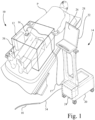
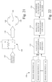
- FIG. 1 there is shown an ultrasound imaging system 10 in accordance with the present invention.
- Ultrasound imaging system 10 includes an electromagnetic (EM) field generator 12, an ultrasound console 14, and an ultrasound probe 16 (handheld). Ultrasound probe 16 is connected to an ultrasound console 14 by a flexible electrical cable 17. Supplemental to ultrasound imaging system 10 is an interventional medical device 18.
- EM electromagnetic
- ultrasound console 14 includes an ultrasound console 14 and an ultrasound probe 16 (handheld).
- ultrasound probe 16 is connected to an ultrasound console 14 by a flexible electrical cable 17.
- interventional medical device 18 Supplemental to ultrasound imaging system 10 is an interventional medical device 18.
- interventional medical device is an elongate intrusive medical device that is configured to be inserted into the tissue, vessel or cavity of a patient.
- interventional medical device 18 may be, for example, a catheter, a lesion crossing catheter such as the CROSSER ® Catheter available from C. R. Bard, Inc., a guide wire, a sheath, an angioplasty balloon, a stent delivery catheter, or a needle. It is intended that the interventional medical device 18 may be considered as a part of the overall ultrasound imaging system 10, but alternatively, also may be considered as an auxiliary part of ultrasound imaging system 10 as a separately provided item.
- Ultrasound imaging system 10 is configured to track the location of the ultrasound probe 16 and interventional medical device 18, and in turn, to operate ultrasound probe 16 such that an active ultrasound transducer array of ultrasound probe 16 is dynamically positioned to image a desired portion of interventional medical device 18, as further described below.
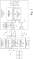
- ultrasound console 14 includes a mobile housing 20, to which is mounted a graphical user interface 22, and a processor circuit 24.
- Graphical user interface 22 may be in the form of a touch-screen display 26 having a display screen 28.
- Graphical user interface 22 is used in displaying information to the user, and accommodates user input via the touch-screen 26.
- touch-screen 26 is configured to display an ultrasound image formed from two-dimensional ultrasound slice data provided by ultrasound probe 16, to display virtual location information of tracked elements within a 3D volume, and to display prompts intended to guide the user in the correct positioning of the ultrasound probe 16 above the area of interest.
- display screen 28 may be configured as a standard 2D display, or optionally, may be configured as a 3D display.
- the 3D dataset captured by ultrasound imaging system 10 may be presented to the user via an autostereoscopic or other display method that presents a 3D image to the user.
- Processor circuit 24 is an electrical circuit that has data processing capability and command generating capability, and in the present embodiment has a microprocessor 24-1 and associated non-transitory electronic memory 24-2.
- Microprocessor 24-1 and associated non-transitory electronic memory 24-2 are commercially available components, as will be recognized by one skilled in the art.
- Microprocessor 24-1 may be in the form of a single microprocessor, or two or more parallel microprocessors, as is known in the art.
- Non-transitory electronic memory 24-2 may include multiple types of digital data memory, such as random access memory (RAM), non-volatile RAM (NVRAM), read only memory (ROM), and/or electrically erasable programmable read-only memory (EEPROM).
- RAM random access memory
- NVRAM non-volatile RAM
- ROM read only memory
- EEPROM electrically erasable programmable read-only memory
- Non-transitory electronic memory 24-2 may further include mass data storage in one or more of the electronic memory forms described above, or on a
- Processor circuit 24 processes program instructions received from a program source, such as software or firmware, to which processor circuit 24 has electronic access. More particularly, processor circuit 24 is configured, as more fully described below, to process location signals received from ultrasound probe 16 and interventional medical device 18, and to generate a digital positioning signal that is conditioned and provided as a control output to ultrasound probe 16. More particularly, the digital positioning signal and control output correspond to a coordinate in the scan axis, e.g., the y-axis, of ultrasound probe 16 where the active ultrasound transducer array of ultrasound probe 16 is to be positioned.
- a program source such as software or firmware
- Processor circuit 24 is communicatively coupled to a probe input/output (I/O) interface circuit 30, a probe position control circuit 31, and a device input/output (I/O) interface circuit 32 via an internal bus structure 30-1, 31-1, and 32-1, respectively.
- the term "communicatively coupled” means connected for communication over a communication medium, wherein the communication medium may be a direct wired connection having electrical conductors and/or printed circuit electrical conduction paths, or a wireless connection, and may be an indirect wired or wireless connection having intervening electrical circuits, such as amplifiers or repeaters.
- Probe input/output (I/O) interface circuit 30 and probe position control circuit 31 are configured to connect to electrical cable 17, which in turn is connected to ultrasound probe 16.
- device input/output (I/O) interface circuit 32 is configured to connect to a flexible electrical cable 34, which in turn is connected to interventional medical device 18.
- EM field generator 12 is placed near the area of interest of the patient P, and is used in triangulating the location of one or more tracked elements, such as the position of ultrasound probe 16 and interventional medical device 18.
- EM field generator 12 may be, for example, the field generator of an Aurora ® Electromagnetic Tracking System available from Northern Digital Inc. (NDI), which generates a base electromagnetic field that radiates in a known orientation to facilitate electromagnetic spatial measurement, which will be referred to hereinafter as an EM locator field 36 (see Fig. 2 ).
- NDI Northern Digital Inc.
- the field strength of the EM locator field 36 defines a detection volume 38, as diagrammatically illustrated as a cube volume, for convenience, in Fig. 1 .
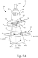
- interventional medical device 18 has a distal tip 40 and a distal end portion 42 extending proximally from the distal tip 40.
- a tracking element 44 i.e., a wire electrical tracking coil
- the term "near" is a range of zero to 2 centimeters (cm)
- the extent of distal end portion 42 is in a range of 1 millimeter (mm) to 3 cm.
- Tracking element 44 allows the location of interventional medical device 18 to be known relative to ultrasound probe 16, as more fully described below.
- Tracking element 44 is configured to generate tip location data defining five degrees of freedom based on the EM locator field 36 generated by EM field generator 12.
- the five degrees of freedom are the X-axis, Y-axis, Z-axis, pitch, and yaw.
- a sixth degree of freedom, i.e., roll, may be also included, if desired.
- Tracking element 44 of interventional medical device 18 is communicatively coupled to processor circuit 24 of ultrasound console 14 via electrical cable 34, serving as a communication link 46 between processor circuit 24 and tracking element 44.
- “communications link” refers to an electrical transmission of data, i.e., information, and/or electrical power signals, over a wired or wireless communication medium.
- the communication link 46 provided by electrical cable 34 is a multi-conductor electrical cable that physically connects tracking element 44 to the ultrasound console 14, and in turn to processor circuit 24.
- communication link 46 may be in the form of a short range wireless connection, such as Bluetooth, via a Bluetooth dongle 48 attached to interventional medical device 18.
- the Bluetooth dongle 48 is configured as a Bluetooth transmitter using Bluetooth protocol, and a corresponding Bluetooth receiver is connected to processor circuit 24.
- Bluetooth dongle 48 communicates tracking information from tracking element 44, and other information associated with interventional medical device 18, such as an operating state, to processor circuit 24 of ultrasound imaging system 10.
- Bluetooth dongle 48 may be used to provide power to the EM tracking components incorporated into interventional medical device 18, in the case where the EM tracking component is an active circuit requiring a power source.
- Bluetooth dongle 48 may be disposable, and included with each interventional medical device 18. Alternatively, Bluetooth dongle 48 may be reusable. Sterility requirements for the reusable dongle are addressed by placing the sterilized dongle in a sterile bag through which a sterile connection to interventional medical device 18 is made.
- ultrasound probe 16 includes a probe housing 50 having a handle portion 52 joined with a head portion 54.
- handle portion 52 has an extent that is generally perpendicular (range of ⁇ 5 degrees) to the extent of head portion 54.
- Ultrasound probe 16 is communicatively coupled to processor circuit 24 of ultrasound console 14 via electrical cable 17, which may be a wired or a wireless connection.
- electrical cable 17 is depicted as a multi-conductor electrical cable that physically connects ultrasound probe 16 to ultrasound console 14, and includes a communication link 56, a communication link 58, and a communication link 60, each formed with wire conductors.
- communication link 56, communication link 58, and communication link 60 may be in the form of a (short range) wireless connection, such as Bluetooth.
- Portions of the processor circuit 24 could also be embedded in the ultrasound probe to analyze or process the received/transmitted signal to the ultrasound emitting element. The analyzed or processed signal is then transmitted back to the console via electrical cable.
- ultrasound probe 16 includes an ultrasound transducer mechanism 62 and a tracking element 64. Both ultrasound transducer mechanism 62 and tracking element 64 are mounted to probe housing 50 (see also Fig. 5A ), and may be contained within probe housing 50, which may be formed from plastic. Also, tracking element 64 may be embedded in the plastic of probe housing 50. Ultrasound transducer mechanism 62 is communicatively coupled to processor circuit 24 via communication links 56 and 58.
- ultrasound transducer mechanism 62 has an active ultrasound transducer array 66 configured to generate two-dimensional ultrasound slice data representing a two-dimensional ultrasound imaging slice 67 at any of a plurality of discrete imaging locations within a three-dimensional imaging volume 68 associated with head portion 54 of ultrasound probe 16.
- the three-dimensional imaging volume 68 is defined by a depth 68-1 of penetration of the ultrasound emission in the direction of the z-axis, a width 68-2 of ultrasound emission in the x-axis, and an ultrasound transducer scan extent 68-3 along the y-axis.
- Active ultrasound transducer array 66 may be, for example, a one-dimensional transducer array in the form of a linear ultrasound transducer array, or alternatively, may be in the form of a convex or concave ultrasound transducer array.
- one-dimensional transducer array is an array of ultrasound transducer elements arranged in a single row, wherein the row may be linear or curved.
- Active ultrasound transducer array 66 is communicatively coupled to processor circuit 24 via communication link 58, and supplies two-dimensional ultrasound data to processor circuit 24 via communication link 58. Automatically, or alternatively based on a user input at graphical user interface 22, processor circuit 24 executes program instructions to store the two-dimensional ultrasound data in mass storage provided in non-transitory electronic memory 24-2.
- processor circuit 24 includes circuitry, or alternatively executes program instructions, to convert the two-dimensional ultrasound data to a form for viewing as a two-dimensional ultrasound image 69 on display screen 28 of graphical user interface 22.
- the two-dimensional ultrasound image 69 depicts interventional medical device 18 having tracking element 44 located in a blood vessel BV, and depicts distal tip 40 of distal end portion 42 of interventional medical device 18 engaged with an intravascular occlusion IC.
- tracking element 64 i.e., a wire electrical tracking coil
- Tracking element 64 is configured to generate probe location data defining six degrees of freedom based on the EM locator field 36 generated by EM field generator 12.
- the six degrees of freedom are the X-axis, Y-axis, Z-axis, pitch, yaw, and roll.
- Tracking element 64 is communicatively coupled to processor circuit 24 via communication link 60, and supplies probe location data to processor circuit 24 via communication link 60. Tracking element 64 allows for the determination of the location of ultrasound probe 16 within detection volume 38 as depicted in Fig. 1 , wherein detection volume 38 is considerably larger (more than 20 times larger) than the three-dimensional imaging volume 68 of ultrasound probe 16 depicted in Fig. 5A .
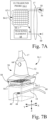
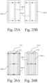
- active ultrasound transducer array 66 of ultrasound transducer mechanism 62 of ultrasound probe 16 may incorporate a movable one-dimensional (1D) transducer array, as in the embodiment depicted in Figs. 6A and 6B .
- active ultrasound transducer array 66 of ultrasound transducer mechanism 62 of ultrasound probe 16 may be in the form of a selectable portion of a two-dimensional (2D) matrix transducer array.
- active ultrasound transducer array 66 is physically movable relative to the probe housing 50, i.e., is dynamically positioned within probe housing 50, in order to capture ultrasound images of locations within the three-dimensional imaging volume 68 (diagrammatically illustrated cube volume, for convenience) beneath ultrasound probe 16.
- ultrasound transducer mechanism 62 includes a one-dimensional (1D) ultrasound transducer array 70, a carriage 72, and a stepper motor 74.
- one-dimensional ultrasound transducer array 70 serves as the active ultrasound transducer array 66.
- the one-dimensional ultrasound transducer array 70 has a row of a plurality of discrete ultrasound transducer elements.
- Carriage 72 is connected to one-dimensional ultrasound transducer array 70, such that one-dimensional ultrasound transducer array 70 moves in unison with carriage 72.
- Carriage 72 converts a rotation of a rotatable shaft 74-1 of stepper motor 74 into a linear translation of carriage 72, and in turn, into a linear translation of one-dimensional ultrasound transducer array 70 relative to head portion 54 of probe housing 50, in a determined one of two translation directions D1, D2.
- Stepper motor 74 is operably connected (electrically and communicatively) to probe position control circuit 31 (see Fig. 2 ) via communication link 56 of electrical cable 17.
- probe position control circuit 31 is in the form of a motor control circuit, which converts the digital positioning signal supplied by processor circuit 24 into a stepper motor positioning signal, which may include multiple stepper motor control signals, and which are supplied by motor control circuit 76 to stepper motor 74 to command rotation of rotatable shaft 74-1 by an amount corresponding to the amount and position dictated by the digital positioning signal.
- the digital positioning signal and the stepper motor positioning signal may be referred to herein collectively as the "positioning signal", since the stepper motor positioning signal is a form change of the digital positioning signal, and the "positioning signal” is considered herein to have been generated by processor circuit 24.
- Carriage 72 converts the rotation of rotatable shaft 74-1 of stepper motor 74 into a linear translation of carriage 72, and in turn, moves one-dimensional ultrasound transducer array 70 relative to head portion 54 of probe housing 50 in a determined one of two translation directions D1, D2, to a location thus dictated by the digital positioning signal generated by processor circuit 24.
- the one-dimensional ultrasound transducer array 70 may be moved to a desired position relative to head portion 54 of probe housing 50.
- Fig. 6B shows an embodiment of carriage 72, wherein carriage 72 has an endless toothed belt 78 suspended between two longitudinally spaced idler gears/pulleys 80-1, 80-2.
- Rotatable shaft 74-1 of stepper motor 74 is connected to a drive gear 82.
- Drive gear 82 is drivably engaged with the teeth of endless toothed belt 78.
- One-dimensional ultrasound transducer array 70 is attached to the lower run 78-1 of endless toothed belt 78, and is movable along the longitudinal extent between the two longitudinally spaced idler gears/pulleys 80-1, 80-2.
- the arrangement of toothed belt 78 suspended between two longitudinally spaced idler gears/pulleys 80-1, 80-2 converts a rotation of the rotatable shaft 74-1 of the stepper motor 74 into a translation of the one-dimensional ultrasound transducer array 70 in a selectable one of the two translation directions D1, D2.
- an alternative ultrasound transducer mechanism 62-1 includes a two-dimensional (2D) ultrasound transducer array 84, and probe position control circuit 31 (see Fig. 2 ) is in the form of a matrix address circuit of the type used in addressing electronic memory.
- Two-dimensional ultrasound transducer array 84 has a plurality of columns 84-1 and a plurality of addressable rows 84-2 of discrete ultrasound transducer elements arranged in a matrix pattern.
- the two-dimensional ultrasound transducer array 84 may be a planar transducer arrangement, or alternatively may be a concave or convex arrangement.
- Two-dimensional ultrasound transducer array 84 is communicatively coupled to processor circuit 24 via communications link 58 to supply two-dimensional ultrasound data from two-dimensional ultrasound transducer array 84 to processor circuit 24.
- probe position control circuit 31 is electrically connected to processor circuit 24 to receive the digital positioning signal generated by processor circuit 24.
- probe position control circuit 31 operates as a matrix address circuit to convert the digital positioning signal supplied by processor circuit 24 into a row selection positioning signal which is supplied to two-dimensional (2D) ultrasound transducer array 84 via communications link 56 to dynamically select one row of the plurality of rows 84-2 of discrete ultrasound transducer elements as the active linear ultrasound transducer array 66.
- the row selection positioning signal corresponds to the position dictated by the digital positioning signal generated by processor circuit 24.
- the row selection positioning signal is a form change of the digital positioning signal
- the digital positioning signal and the row selection positioning signal may be referred to herein collectively as the "positioning signal”, and the "positioning signal” is considered herein to have been generated by processor circuit 24.
- Figs. 7A and 7B emulates the dynamic positioning of the one-dimensional ultrasound transducer array 70 discussed above with respect to Figs. 6A and 6B , and allows for similar control of where the ultrasound probe will image within the three-dimensional imaging volume 68 beneath the ultrasound probe (see Fig. 5A ).
- ultrasound imaging system 10 provides a "lock-on" functionality, wherein the position of each of the ultrasound probe 16 and interventional medical device 18 are tracked, and the active ultrasound transducer array 66 in ultrasound probe 16 is dynamically positioned at a convergence of the tracking information, which is further described with reference to the flowchart of Fig. 8 .
- processor circuit 24 is communicatively coupled to each of the tracking element 44 of interventional medical device 18, tracking element 64 of ultrasound probe 16, ultrasound transducer mechanism 62 of ultrasound probe 16, and to the graphical user interface 22 having display screen 28.
- processor circuit 24 executes program instructions to determine the type of tracking elements that are associated with each of ultrasound probe 16 and interventional medical device 18, the communications rate between processor circuit 24 and each of ultrasound probe 16 and interventional medical device 18, the rate of data acquisition updating, and probe parameters.
- probe parameters may include, scan extent start point and end point, and the desired velocity of the movement of active ultrasound transducer array 66, with respect to the origin point 71 (see Fig. 5A ), defining the 0, 0, 0 location in the X, Y, and Z axes.
- the location of tracking elements of ultrasound probe 16 and interventional medical device 18 may be calibrated with respect to the 3D detection volume 38 defined by EM field generator 12 (see Fig. 1 ).
- WHILE defines the entry into a continuous loop to virtually converge the position of the ultrasound imaging plane of active ultrasound transducer array 66 of ultrasound probe 16 with the position of tracking element 44, and in turn distal tip 40, of interventional medical device 18.
- Processor circuit 24 remains in this continuous loop until the program execution is stopped.
- the current position of tracking element 44 of interventional medical device 18 is determined in relation to the 3D detection volume 38 defined by EM field generator 12.
- tracking element 44 of interventional medical device 18 generates tip location data as physical coordinates based on the EM locator field 36 generated by EM field generator 12, and provides the tip location data associated with the physical coordinates to processor circuit 24.
- step S106 in parallel to step S104, the current position of tracking element 64 of ultrasound (US) probe 16 is determined in relation to the 3D detection volume 38 defined by EM field generator 12.
- tracking element 64 of ultrasound probe 16 generates probe location data as physical coordinates based on the EM locator field 36 generated by EM field generator 12, and provides the probe location data associated with the physical coordinates to processor circuit 24.
- an ultrasound plane position (B-scan position) is determined based on the probe location data.
- processor circuit 24 executes program instructions to define a unit vector, i.e., the Z-axis at origin point 71 (0,0,0) of Fig. 5A , that is perpendicular to (e.g., points downwardly from) the surface of head portion 54 of ultrasound probe 16, wherein the unit vector initially lies on a current ultrasound image plane.
- Processor circuit 24 executes program instructions to virtually rotate the vector to be normal to the current ultrasound image plane.
- Processor circuit 24 then executes program instructions to rotate the normal vector about the Z-axis using the probe location data acquired at step S106, which corresponds to the orientation angle of ultrasound probe 16.
- the Equation 2 offset calculation gives the minimum, or perpendicular, distance from tracking element 44 of interventional medical device 18 to the ultrasound plane position, which is the distance (and direction) that ultrasound transducer mechanism 62 needs to move active ultrasound transducer array 66 so that there is a convergence (intersection) of the ultrasound position plane with the tracking element 44, and in turn distal tip 40, of interventional medical device 18.
- the calculation determines the offset used to achieve a convergence of the tip location data with the ultrasound plane position associated with the probe location data.
- ultrasound transducer mechanism 62 is driven to position active ultrasound transducer array 66 at the determined point of convergence as defined by the OFFSET calculated at step S110.
- processor circuit 24 executes program instructions to process the OFFSET to generate the positioning signal corresponding to the point of convergence, and the positioning signal is communicatively coupled to ultrasound transducer mechanism 62 to dynamically position active ultrasound transducer array 66 at a desired imaging location of the plurality of discrete imaging locations, so that the two-dimensional ultrasound slice data captured by active ultrasound transducer array 66 includes an image of at least the distal tip 40 of interventional medical device 18, so long as distal tip 40 of the interventional medical device 18 remains in the three-dimensional imaging volume 68 under the surface of the head portion of ultrasound probe 16.
- the positioning signal will culminate in stepper motor control signal that are supplied to stepper motor 74.
- the positioning signal will culminate in a row selection signal supplied to two-dimensional ultrasound transducer array 84.
- under or underlying with respect to ultrasound probe 16, means within the possible imaging view extent of ultrasound probe 16.
- step S102 "WHILE"
- WHILE WHILE
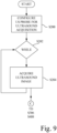
- FIG. 9 there is shown a flowchart describing the acquisition of ultrasound data concurrently with, i.e., during, the "lock-on" function described above with respect to Fig. 8 .
- ultrasound probe 16 is configured for acquisition of ultrasound data. For example, parameters such as the desired resolution, and emission strength of active ultrasound transducer array 66 to achieve a desired depth of penetration, may be set.
- ultrasound imaging system 10 is configured to collect a series of two-dimensional ultrasound imaging slices (ultrasound B-scan) data.
- ultrasound imaging system 10 is configured to collect a series of ultrasound B-scan data to form three-dimensional ultrasound volumetric data representing the three-dimensional imaging volume 68, from which C-scan data, or other plane oriented data, may be derived.
- WHILE defines the entry into a continuous loop for acquisition of ultrasound data with active ultrasound transducer array 66 of ultrasound probe 16.
- processor circuit 24 is configured to execute program instructions, or alternatively includes circuitry, to process two-dimensional ultrasound slice data generated by the active ultrasound transducer array 66 of ultrasound transducer mechanism 62 of ultrasound probe 16, and to generate the ultrasound image for display at display screen 28 of graphical user interface 22. Also, processor circuit 24 may execute program instructions to automatically store the two-dimensional ultrasound slice data in non-transitory electronic memory 24-2, and thus accumulate multiple image data sets of the location of interest. Alternatively, graphical user interface 22 may provide a user command to processor circuit 24 to store the two-dimensional ultrasound slice data in non-transitory electronic memory 24-2 on demand at the command from a user.
- a series of two-dimensional ultrasound imaging slices (ultrasound B-scan) data is collected and stored in non-transitory electronic memory 24-2.
- active ultrasound transducer array 66 is scanned along the Y-axis across all, or a selected portion, of the three-dimensional imaging volume 68 to take a detailed volumetric scan of the underlying area beneath head portion 54 of ultrasound probe 16, such that a series of ultrasound B-scan data representing the three-dimensional imaging volume is collected and stored in non-transitory electronic memory 24-2.
- step S202 "WHILE"
- ultrasound imaging system 10 is able to dynamically position active ultrasound transducer array 66 to converge at a desired imaging location of the plurality of discrete imaging locations in the three-dimensional imaging volume 68 so that the two-dimensional ultrasound slice data includes an image of at least the distal tip 40 of interventional medical device 18 in generating the ultrasound image displayed on display screen 28.
- a motion indicator 88 located on at least one of the ultrasound probe 16 and the display screen 28 of graphical user interface 22 (see also Fig. 2 ) is provided to guide the user to an acceptable placement of ultrasound probe 16 relative to the tracked interventional medical device 18.
- Motion indicator 88 is operably coupled to processor 24, and may be in the form of directional arrows that may be selectively illuminated by processor circuit 24 so as to guide the user to an acceptable placement of ultrasound probe 16 relative to the tracked interventional medical device 18.
- processor circuit 24 executes program logic to determine whether tracking element 44 of interventional medical device 18 is outside the three-dimensional imaging volume 68, and thus is outside the imageable range of ultrasound probe 16.
- processor circuit 24 executes program instructions to determine whether the distal tip 40 of the interventional medical device 18 is presently located outside the three-dimensional imaging volume 68.
- processor circuit 24 of ultrasound imaging system 10 further executes program instructions to generate a visual prompt at motion indicator 88 to prompt the user to move head portion 54 of ultrasound probe 16 in a particular direction to a general location such that tracking element 44, and thus distal tip 40, of interventional medical device 18 resides in the three-dimensional imaging volume 68 under ultrasound probe 16, thereby permitting the active ultrasound transducer array 66 of ultrasound probe 16 to automatically capture ultrasound image data containing the tracking element 44 and distal tip 40 of interventional medical device 18 for display on display screen 28.
- interventional medical device 18 traverses the three-dimensional imaging volume 68, the user may operate graphical user interface 22 to store a reference location, i.e., a seed point, in memory 24-2 at each of one or more particular regions of interest within the three-dimensional imaging volume 68, so as to facilitate a quick and accurate return to a marked location within the three-dimensional imaging volume 68.
- a reference location i.e., a seed point
- a specific location may be designated via its coordinates within ultrasound imaging system 10.
- a visual marker indicating this location may also be displayed to the user within the 3D virtual environment, and persist on display screen 28 for a period of time designated by the user at graphical user interface 22. These markers may be used to denote clinically relevant locations that the user may return to during a vascular procedure.
- location information from ultrasound probe 16 and interventional medical device 18 is further used to move the position of the active ultrasound transducer array 66 of ultrasound probe 16, which allows ultrasound imaging system 10 to converge on a two-dimensional ultrasound image slice that includes the underlying interventional medical device 18, even if ultrasound probe 16 is not placed directly over tracking element 44/distal tip 40 of interventional medical device 18.
- a linear offset may be selected at graphical user interface 22 to shift the location of convergence along the length of the interventional medical device 18, in the event that the desired ultrasound image slice does not directly coincide with the position of the tracking element 44/distal tip 40.
- Such an offset may be either proximal or distal to the position of the tracking element 44, and may be in the form of a distance.
- a rotational offset may be selected at graphical user interface 22 to change a rotational position of the two-dimensional ultrasound image slice relative to a longitudinal axis of interventional medical device 18, and may be in the form of an angular increment.
- the position of the active ultrasound transducer array 66 of ultrasound probe 16 is dynamically adjusted in near real time, limited by data acquisition and processing speed, which allows ultrasound imaging system 10 to adapt to small changes in position of ultrasound probe 16, the position of the tracking element 44 of interventional medical device 18, and/or the patient position, such that an ultrasound image of the underlying interventional medical device 18 is maintained within view of ultrasound probe 16.
- positioning prompts in the form of motion indicator 88 are again generated and used to prompt the user to move ultrasound probe 16 in a direction that allows ultrasound imaging system 10 to again converge on, and display, an ultrasound image of the underlying interventional medical device 18.
- Ultrasound imaging system 10 also may be operated in a three-dimensional (3D) high resolution scan imaging mode, with reference to step S204 of Fig. 9 .
- the ultrasound probe 16 in the three-dimensional (3D) high resolution imaging mode the ultrasound probe 16 is held in a fixed position over an area of interest, and the active ultrasound transducer array 66 is scanned along the Y-axis across all, or a selected portion, of the three-dimensional imaging volume 68 to take a detailed volumetric scan of the underlying area beneath head portion 54 of ultrasound probe 16.
- Ultrasound probe 16 may be held in the fixed position by the hand of the user. Metadata containing the position location from each two-dimensional slice obtained in the high resolution mode is further used to identify images taken from the same point in space, and subsequently used for image integration processing.
- processor circuit 24 of ultrasound console 14 is configured to execute program instructions to generate a scanning signal that is supplied to ultrasound transducer mechanism 62 to scan active ultrasound transducer array 66 over at least a portion of the three-dimensional imaging volume 68.
- the active ultrasound transducer array 66 is repeatedly actuated during the scan to generate a plurality, i.e., a series, of sequential two-dimensional ultrasound slices, which are stored in memory 24-2, and combined to form the 3D ultrasound volumetric data from which a three-dimensional (3D) high resolution ultrasound image is formed and displayed on display screen 28 of graphical user interface 22 (see also Fig. 2 ).
- the quality of the high resolution 3D images may be improved by generating a composite ultrasound image of the location of interest. Because the location of the ultrasound probe 16 is known by processor circuit 24, multiple sets of 2D or 3D, ultrasound images of a particular location in the three-dimensional imaging volume 68 underlying, e.g., perpendicular to, the surface of the head portion 54 of ultrasound probe 16 may be taken, and stored in non-transitory electronic memory 24-2, from which a compound composite ultrasound image may be generated from the multiple sets of 2D, or 3D, ultrasound images by summing together the multiple sets of ultrasound images of the same location.
- processor circuit 24 is configured to execute program instructions to operate the active ultrasound transducer array 66 to generate multiple sets of ultrasound image data that includes metadata corresponding to a particular location, i.e., metadata describing the location of the scan within the three-dimensional volume 68, and save the multiple sets in non-transitory electronic memory 24-2.
- Processor circuit 24 is further configured to execute program instructions to sum the multiple sets of ultrasound image data to generate composite (compound) ultrasound image data, which is then stored in non-transitory memory 24-2 and/or is displayed on display screen 28 of graphical user interface 22.
- the quality of the high resolution 3D images also may be improved by tracking the position of the patient P in relation to the position of ultrasound probe 16 to reduce motion artifacts in the 3D images.
- a third EM tracking element 90 i.e., a wire electrical tracking coil
- Tracking element 90 is communicatively coupled to processor circuit 24 of ultrasound console 14 by a communication link 92, such as a wired or wireless connection.
- Tracking element 90 when energized by electromagnetic (EM) field generator 12, generates three-axis patient location data, which is supplied via communications link 92 to processor circuit 24.
- EM electromagnetic
- Processor circuit 24 processes the three-axis patient location data to further adjust the position of the active ultrasound transducer array 66 of ultrasound probe 16 in response to any motion of the patient.
- tracking element 90 allows for the position of the patient to be known, which in turn allows ultrasound imaging system 10 to adjust the position of the active ultrasound transducer array 66 of ultrasound probe 16 to any motion created by the patient.
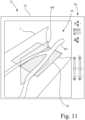
- Ultrasound imaging system 10 also may be operated to render and display one or more synthetic (user chosen) scan planes.
- a plurality, i.e., a series, of sequential two-dimensional ultrasound slices may be generated and combined to generate 3D ultrasound volumetric data defining a three-dimensional imaging volume.
- the user may select for rendering and display one or more synthetic (user chosen) scan planes, such as a coronal scan plane 98 and an axial (sagittal) scan plane 100.
- the user may define, using user controls 96, a desired synthetic plane orientation with respect to the 3D ultrasound volumetric data associated with three-dimensional ultrasound image 94.
- processor circuit 24 of ultrasound imaging system 10 executes program instructions to identify within the 3D ultrasound volumetric data of three-dimensional ultrasound image 94 the image data associated with the desired synthetic plane orientation.
- the desired synthetic plane may pass through multiple two-dimensional image data slices in the 3D ultrasound volumetric data.
- the desired one or more synthetic (user chosen) scan planes may be rendered and displayed on display screen 28 of graphical user interface 22 within the generated three-dimensional ultrasound image 94 as shown in Fig. 11 , or as standalone two-dimensional images.
- Various views such as those associated with the sagittal plane, the transverse plane, and the coronal plane, may be visualized, and a slice from one or more, or all, of the planes, as defined by the location of the tracked device(s), e.g., tracking element 44 of interventional medical device 18 and/or tracking element 64 of ultrasound probe 16, can be displayed, individually or as a group.
- the tracked device(s) e.g., tracking element 44 of interventional medical device 18 and/or tracking element 64 of ultrasound probe 16
- scan planes that do not exist at 90 degrees from each other could also be defined and selected by the user. Additionally, the user defined scan planes may not be planar, and may follow a curved path.
- Another aspect of the present invention provides for a focusing of the three-dimensional imaging volume around a determined region of interest, i.e., the region around the location of tracking element 44 of interventional medical device 18, by reducing the scan extent along the Y-axis (see Fig. 5A ), thus reducing the amount of three-dimensional ultrasound volumetric data required to adequately view the region surrounding interventional medical device 18.
- the scan extent of active ultrasound transducer array 66 along the Y-axis is reduced, i.e., focused, to that of most interest, thus reducing scanning time and the amount of data required to adequately represent the three-dimensional volume of interest.
- processor circuit 24 executes program instructions to determine a region of interest in the three-dimensional ultrasound volumetric data defining the three-dimensional imaging volume 68.
- Processor circuit 24 also executes program instructions to reduce the scan range of the active ultrasound transducer array 66 of the ultrasound transducer mechanism 62 along the Y-axis for acquisition of subsequent three-dimensional ultrasound volumetric data at the region of interest from that of the scan range of the previous scan, so as to reduce the amount of acquired three-dimensional ultrasound volumetric data from that of the prior scan.
- user controls 96 of graphical user interface 22 may include one or more slice selection sliders 102, such as a coronal slider 102-1 and a sagittal slider 102-2, to provide a sequential variation from an automatically, or manually, selected two-dimensional ultrasound image slice being displayed.
- slice selection sliders 102 such as a coronal slider 102-1 and a sagittal slider 102-2
- a plurality, i.e., a series, of sequential two-dimensional ultrasound B-scan imaging slices 67 may be generated and combined to generate 3D ultrasound volumetric data defining a three-dimensional imaging volume 68.
- a desired two-dimensional ultrasound image slice on a desired imaging plane may be generated from the 3D ultrasound volumetric data that includes a particular region of interest, such as distal tip 40 of interventional medical device 18.
- the desired two-dimensional ultrasound image slice may be in an imaging plane different from that of the native B-scan imaging plane of the sequential two-dimensional ultrasound imaging slices 67 that when combined form the 3D ultrasound volumetric data defining the three-dimensional imaging volume 68.
- slice selection sliders 102 permit the user to select a slice in each of one or more imaging planes for display, if desired, wherein the selected two-dimensional ultrasound image slice may intersect, or lie on either side of, the two-dimensional ultrasound image slice that was automatically, or manually, selected.
- the slice selection sliders 102 are configured to provide a sequential parallel variation from the initially selected two-dimensional ultrasound image slice to manually select a second two-dimensional ultrasound image slice parallel to the initially selected two-dimensional ultrasound image, wherein the second two-dimensional ultrasound image slice lies on either side of the initially selected two-dimensional ultrasound image slice.
- Fig. 12 is a pictorial representation at graphical user interface 22 depicting a selection of a sagittal plane slice 104 extending through a series of two-dimensional ultrasound image slices 67 in the three-dimensional imaging volume 68 at sagittal slice location 270.
- sagittal slider 102-2 By manipulation of sagittal slider 102-2 using one of the up-down arrows, sagittal slice location 271, or others 1-269 or 272-560, parallel to the sagittal slice location 270 may be selected for display.
- Fig. 13 is a pictorial representation depicting a selection of a coronal plane slice 106 extending through a series of two-dimensional ultrasound image slices 67 in a three-dimensional imaging volume 68 at coronal slice location 150.
- coronal slider 102-1 By manipulation of coronal slider 102-1 using one of the up-down arrows, coronal slice location 151, or others 1-149 or 152-560, may be selected for display.
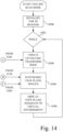
- FIG. 14 there is shown a flowchart describing the generation of a 3D ultrasound image as a set of three orthogonal ultrasound images.
- ultrasound imaging system 10 is initialized for rendering a 3D ultrasound image as a set of three orthogonal images, such as setting up processor circuit 24 and graphical user interface 22 for construction of 3D models.
- WHILE defines the entry into a continuous loop for generation and updating of the displayed 3D ultrasound image.
- an ultrasound (US) volume transform node is updated based on the position of ultrasound probe 16, as determined at step S106 of Fig. 8 .
- processor circuit 24 executes program instructions to move the 3D model of the three-dimensional imaging volume 68 to match the current position of ultrasound probe 16.
- processor circuit 24 executes program instructions to choose a two-dimensional ultrasound imaging slice 67 (B-scan) from a C-scan data slice that includes the tracking element 44, and in turn the distal tip 40, of interventional medical device 18.
- B-scan two-dimensional ultrasound imaging slice 67
- processor circuit 24 executes program instructions to generate 3D display data representative of three orthogonal images in a virtual 3D environment associated with the three-dimensional imaging volume 68 matched to the current position of ultrasound probe 16.
- Processor circuit 24 sends the 3D display data to user interface 22 for display on display screen 28 as three orthogonal images that include the tracking element 44, and in turn the distal tip 40, of interventional medical device 18.
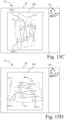
- Figs. 15A, 15B , 15C and 16 there is described below a patient oriented imaging window mode.
- that which was rendered as "up” on the ultrasound display screen followed the orientation of the ultrasound probe.
- the orientation of the displayed ultrasound image is true to the orientation of the patient, regardless of the actual orientation of the ultrasound probe.
- Fig. 15A shows a diagrammatic illustration of ultrasound probe 16 taking a two-dimensional ultrasound imaging slice 67 of a portion of a leg L of a patient.
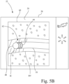
- Fig. 15B is a diagrammatic illustration of graphical user interface 22 having a patient oriented imaging window 108 depicting a patient oriented virtual environment on display screen 28 of graphical user interface 22, wherein the location and orientation of the acquired ultrasound image data is rendered on the display screen 28 to correspond to the orientation of the patient P, wherein the orientation and location of where the ultrasound image is being acquired relative to a position of the patient P is indicated and communicated to the clinician via use of the virtual environment.
- Fig. 15B shows a diagrammatic illustration of graphical user interface 22 having patient oriented imaging window 108 including an image of leg L, rendered as an actual image of patient leg L or as a computer generated virtual rendering, and including a virtual rendering of ultrasound probe 16 and two-dimensional ultrasound imaging slice 67 that is generated by ultrasound probe 16.
- a secondary imaging window 110 including a computer generated virtual rendering, i.e., a graphic, of the orientation of the body of patient P, as well as an UP arrow indicating the orientation of the UP relative to the patient.
- the display of the ultrasound image on display screen 28 of graphical user interface 22 may be adjusted such that a vertical "top” 67-1 of the acquired ultrasound image data of two-dimensional ultrasound imaging slice 67, or the vertical top of the acquired volumetric data in 3D data acquisition, is always rendered as "UP" on display screen 28 relative to the position of the patient P, and regardless of the actual orientation of ultrasound probe 16 relative to the patient. In other words, even if the actual orientation of ultrasound probe 16 is changed relative to the position of the leg L from that depicted in Fig.
- the orientation of the ultrasound image on display screen 28 of graphical user interface 22 remains as depicted in Fig. 15C .
- features of the displayed image such as the upper blood vessel 107-1, and the lower-left blood vessel 107-2, are always displayed in the correct orientation relative to the patient P.
- FIG. 15D depicts the ultrasound image generated in Fig. 15A as it would be rendered in accordance with the prior art, wherein the orientation of the acquired ultrasound image data rendered on the display screen does not correspond to the orientation of the patient.
- the image is rendered on the display screen wherein the ultrasound probe head is in a virtual position at the top of the display screen and the bottom on the display screen always corresponds to the distal extent of the generated ultrasound image. More particularly, with the ultrasound probe oriented as depicted in Figs. 15A and 15B , the prior art rendered ultrasound image would position the upper blood vessel 107-1 and the lower-left blood vessel 107-2 on the display screen as shown in Fig.
- the displayed image no longer corresponds to the orientation of the patient P. Rather, as shown in Fig. 15D , using arrow 112 to designate the true "up" orientation, the prior art ultrasound image is actually rendered to face toward the left on the display screen. Accordingly, in the prior art, the ultrasound technician was required to mentally associate the orientation of the displayed image with that of the actual orientation of the patient.
- the patient oriented imaging window aspect of the present invention described above with respect to Figs. 15A, 15B and 15C , generates a virtual environment that aids a clinician, including a person not experienced in ultrasound imaging, in successful image acquisition.
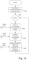
- Fig. 16 is a flowchart of a patient oriented imaging window mode, i.e., a virtual environment imaging mode, associated with the generation of the patient oriented imaging window as depicted above with respect to Figs. 15A, 15B and 15C .
- a patient oriented imaging window mode i.e., a virtual environment imaging mode
- ultrasound imaging system 10 is initialized for rendering a 3D ultrasound image, such as setting up processor circuit 24 and graphical user interface 22 for construction of 3D models, initializing a camera video data transfer, and configuring appropriate patient lighting for video.
- WHILE defines the entry into a continuous loop for generation and updating of the displayed patient oriented imaging window 108 as depicted in Figs. 15B and 15C .
- an ultrasound (US) volume transform node is updated based on the position of ultrasound probe 16, as determined at step S106 of Fig. 8 .
- processor circuit 24 executes program instructions to move the 3D model of the three-dimensional imaging volume 68 (see Fig. 5A ) to match the current position of ultrasound probe 16.
- an ultrasound (US) image transform node is updated based on the calculated OFFSET from step S110 of Fig. 8 .
- processor circuit 24 executes program instructions to update the ultrasound image transform node by moving a 3D model of the three-dimensional ultrasound imaging data to match the current two-dimensional ultrasound imaging slice 67 (B-scan) acquired from ultrasound probe 16.
- processor circuit 24 executes program instructions to display the two-dimensional ultrasound imaging slice 67 (B-scan) in a 3-D environment in the patient oriented imaging window 108, such that the vertical "top” 67-1 of the acquired ultrasound image data of two-dimensional ultrasound imaging slice 67, or the vertical top of the acquired volumetric data in 3D data acquisition, is always rendered as "up” on display screen 28 relative to the position of the patient, and regardless of the actual orientation of ultrasound probe 16 relative to the patient.
- step 402 "WHILE"
- this offset, or depth information can further be used to dynamically control some of the ultrasound imaging settings in near real time, as identified below. This allows the system to optimize the image quality settings such that the best image of the interventional medical device 18 is displayed to the user at display screen 28.
- the ultrasound imaging settings that may be dynamically controlled because the z-axis offset from the ultrasound probe 16 can be calculated may include:
- multiple 2D ultrasound, e.g., B-mode, image slices acquired from different points within the detection volume 38 may be integrated into a larger volumetric stack of images. These images may then be combined to display ultrasound images that represent a composite of multiple 2D ultrasound image slices taken at different time periods.
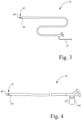
- the following steps may be taken to extract an extended image that exceeds the length of one 2D ultrasound image: collect a spherical amount of data at a preselected radii from distal tip 40 of interventional medical device 18 as interventional medical device 18 is advanced through a vasculature lumen; store a radial data set corresponding to the spherical amount of data to memory 24-2 as interventional medical device 18 is advanced through the vasculature lumen; and, from the stored radial data set, construct virtual scan planes that produce a virtual scan plane that exists along the length of the interventional medical device 18.
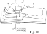
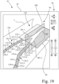
- ultrasound imaging system 10 is configured to automatically determine, render and display one or more synthetic scan planes that are aligned with a longitudinal axis 18-1 of distal end portion 42 of interventional medical device 18.
- Axis 18-1 of interventional medical device 18 will be determined based on information relating to the position of tracking element 44 at distal end portion 42 of interventional medical device 18.
- 3D ultrasound image 120 includes an image of leg L and blood vessel BV having blood vessel branches BV-1 and BV-2.
- a plurality, i.e., a series, of sequential two-dimensional ultrasound slices may be generated and combined to generate 3D ultrasound volumetric data defining a 3D imaging volume.
- ultrasound imaging system 10 will execute program instructions to automatically generate synthetic scan planes for rendering and display, such as a coronal plane 124, a sagittal plane 126, and an axial plane 128.
- Each of coronal plane 124 and sagittal plane 126 has a longitudinal extent corresponding to a direction of the longitudinal extent of axis 18-1 of interventional medical device 18.
- At least one of coronal plane 124 and sagittal plane 126 will include a lengthwise view of at least the distal end portion 42 of interventional medical device 18 and a lengthwise cross-section of blood vessel BV.
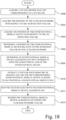
- FIG. 18 there is shown a flowchart describing a method of implementing an interventional medical device aligned mode, associated with the depiction of Fig. 17 .
- Each of the steps, i.e., acts, of the method of Fig. 18 may be implemented as program instructions executed by processor circuit 24.
- the position (e.g., the four axes of freedom, x, y, z, and rotational) of ultrasound probe 16 is acquired with respect to the 3D detection volume 38, i.e., the 3D world space. This may be acquired as in step S106 of Fig. 8 , wherein the current position of tracking element 64 of ultrasound probe 16 is determined in relation to the 3D detection volume 38 defined by EM field generator 12 (see also Fig. 1 ).
- Steps S502 and S504 are performed in a continuous loop for generation and updating of the displayed 3D ultrasound image.
- an interventional medical device-aligned plane that intersects with the longitudinal axis of the interventional device is determined.
- the interventional medical device-aligned plane may be, for example, sagittal plane 126 depicted in Fig. 17 , from which the coronal and axial plane 128 also may be determined.
- the interventional medical device-aligned plane may be defined with a normal in the direction of the cross-product of the longitudinal axis 18-1 of interventional medical device 18 and a vertical unit vector.
- the seed points associated with blood vessel branch BV-1 are designated as 132-1, 132-2, 132-3, 132-4 and 132-5
- the seed points associated with blood vessel branch BV-2 are designated as 133-1, 133-2, 133-3, 133-4, 133-5, and 133-6, and are graphically represented on display screen 28 as circular (oval) features representing the edges of the vasculature tubes of blood vessel branches BV-1 and BV-2.
- the display includes a 3D ultrasound image portion 134 (corresponding to three-dimensional ultrasound image 94) and a virtual image portion 136.
- Virtual image portion 136 is distinguished from the 3D ultrasound image portion 134 on display screen 28 by an identifying contrast, such a differing color, e.g., red (shown by convention as parallel vertical lines).
- the virtual image portion 136 depicts the corresponding blood vessel structure without the surrounding tissue structure.
- virtual image portion 136 includes a 3D segmentation model 136-1 corresponding to blood vessel branch BV-1 and a 3D segmentation model 136-2 corresponding to blood vessel branch BV-2.
- 3D segmentation model 136-1 is rendered from a plurality of connected virtual image segments individually identified as virtual image segments 138-1, 138-2, 138-3, 138-4, and 138-5.
- 3D segmentation model 136-2 is rendered from a plurality of connected virtual image segments individually identified as virtual image segments 139-1, 139-2, 139-3, 139-4, 139-5 and 139-6.
- virtual image segment means an extrapolated portion that extends from a reference point to an end point, such as between a pair of adjacent seed points, or within a range of a predetermined number of consecutive 2D ultrasound images, e.g., a range that includes 30 consecutive 2D ultrasound images.
- virtual image segment 138-1 lies between seed points 132-1 and 132-2
- virtual image segment 138-2 lies between seed points 132-2 and 132-3
- virtual image segment 139-1 lies between seed points 133-1 and 133-2
- virtual image segment 139-2 lies between seed points 133-2 and 133-3, etc.
- a 3D rendering of the underlying vasculature may be extracted from a set of 2D ultrasound, e.g., B-mode, images acquired by the ultrasound probe 16, and a virtual representation of the 3D vasculature may be displayed along with other 2D display data on display screen 28.
- This virtual representation thus serves as a 3D virtual map of the vasculature to further orient the user as to the location of vessels, bifurcations, and other adjacent anatomy that is not displayed via a particular 2D ultrasound slice.
- Figs. 20A and 20B form a flowchart of a segmentation method to achieve 2D virtual image segmentation that may be used to implement the segmentation mode in the generation of a 3D segmentation model as a virtual representation of the vasculature in accordance with an aspect of the present invention.
- Each of the steps, i.e., acts, of the method of Figs. 20A and 20B may be implemented as program instructions executed by processor circuit 24, unless otherwise indicated.
- a 3D volume of 3D ultrasound data which includes metadata for the location of each 2D ultrasound image, i.e., slice, within the 3D volume is acquired via a scanning of ultrasound probe 16 to form a 3D dataset.
- a 2D ultrasound image is displayed to the user on display screen 28, from which the user can select an open lumen of interest of the vasculature, as a basis for segmentation.
- the presence of Doppler flow within a candidate lumen of the vasculature may be used to select an area on the image for designation as an intraluminal space.
- the user selects an open lumen of interest of the vasculature on the displayed 2D ultrasound image.
- the user selection of the open lumen may be accomplished via graphical user interface 22, e.g., via touch screen display 26, via a cursor on display screen 28, or other method used to indicate a location on the displayed 2D ultrasound image.
- the user selects a beginning point, e.g., a previously stored intraluminal seed point, associated with vasculature, e.g., BV-1, as a point to begin the virtual image segmentation.
- the beginning seed point may be, for example, seed point 132-1 of the prior user defined seed points (see Fig. 19 ).
- the user selection may be accomplished via graphical user interface 22, e.g., via touch screen display 26, via a cursor on display screen 28, etc.
- a segmentation algorithm such as an edge detection algorithm, is invoked to further expand and designate the full luminal area of the open lumen of interest of a current 2D ultrasound image slice.
- the segmentation algorithm will be invoked with respect to the beginning seed point of the current 2D ultrasound image slice. Thereafter, the segmentation algorithm will be invoked with respect to the selected open lumen of the next adjacent 2D ultrasound image slice.
- step S609 it is determined whether this is the first iteration from the current seed point. If NO, then the process proceeds to step S614.
- step S609 determines whether the determination at step S609 is YES. If the determination at step S609 is YES, then the process proceeds to step S610.
- step S610 the full luminal area of the open lumen of interest of the current 2D ultrasound image is then displayed to the user at display screen 28.
- step S612 if the user designates, at graphical user interface 22, that the full luminal area of the open lumen of interest being displayed is not accurate (decision is NO), then the process returns to step S606 to re-select a beginning seed point, or alternatively, the process may end.
- step S612 if the user designates, at graphical user interface 22, that the full luminal area of the open lumen of interest being displayed is accurate (decision is YES), then the process proceeds to step S614.
- step S614 the data associated with the full luminal area of the open lumen is saved to memory 24-2.
- a center point of the full luminal area of the current 2D ultrasound image slice is then calculated, such as by using a 2d mean squared calculation.
- the center point is then projected onto an adjacent 2D ultrasound image slice of the set of 2D ultrasound images.
- adjacent refers to two 2D ultrasound images that are sequentially next to one another.
- step S620 it is determined whether the next user selected seed point, e.g., seed point 132-2 as approached from seed point 132-1 (see Fig. 19 ), has been reached.
- the adjacent 2D ultrasound image slices are then joined, i.e., stitched together, to render a semi-transparent 3D segmentation model, e.g., at this stage, a portion of the 3D segmentation model 136-1 depicted in Fig. 19 .
- step S624 the current rendering of the 3D segmentation model is persistently displayed within a 3D scene graph on display screen 28, as shown in Fig. 19 .
- the process then returns to step S608, and steps S608-S118 are repeated.
- step S620 If the result at step S620 is YES, i.e., that the next seed point, e.g., seed point 132-2 (see Fig. 19 ), has been reached, then the current virtual image segment, e.g., virtual image segment 138-1, has been completed, and the process proceeds to step S626.
- the next seed point e.g., seed point 132-2 (see Fig. 19 )
- the current virtual image segment e.g., virtual image segment 138-1
- Step S626 it is determined whether it is desired to generate another virtual image segment.
- Step S626 may be a user intervention point in the process, wherein the process waits on a user entered determination at graphical user interface 22, or alternatively, may be a decision made by the program logic based on a predetermined selection made by the user at graphical user interface 22 (e.g., the user selects a quantity of virtual image segments that will form the 3D segmentation model.
- step S608 the process returns to step S608 to start assembling the next virtual image segment, e.g., virtual image segment 138-2, for rendering as the 3D segmentation model, which is dynamically expanding at each iteration of the process, and which may continue until the entirety of the 3D segmentation model 136-1 depicted in Fig. 19 is complete.
- step S626 determines whether the desired segmentation and dynamic formation of the 3D segmentation model is complete, and the process ends. It is to be understood, however, that the process described above may be repeated to render and display the 3D segmentation model 136-2 also depicted in Fig. 19 .
- each 3D segmentation model may be made up of at least one virtual image segment, e.g., virtual image segment 138-1, and may include a plurality of virtual image segments, e.g., virtual image segments 138-1, 138-2, 138-3, 138-4, etc.
- 2D ultrasound images i.e., image slices, that bisect the vasculature may also be rendered and displayed to the user within this 3D user environment.
- additional ultrasound planes such as the coronal plane, may be rendered and displayed to the user.
- the process described above may designate the number of 2D ultrasound image slices, e.g., 25-50 slices, that are to constitute a virtual image segment, and the process described above is repeated for the selected number of 2D ultrasound image slices.
- the slice selection/localization is performed based on magnetic tracking.
- other tracking methods may be used in accordance with the present invention.
- Fig. 21 depicts an LRC tissue model 140 that represents tissue as an inductor (L), resistor (R), capacitor (C) circuit which receives a high frequency source signal 142, in a frequency range of 19k Hertz to 2M Hertz.
- the system detects the Doppler frequency shift that is created in the ultrasound return signal 144 due to fluid motion (e.g., blood) or due to the motion of the surrounding tissues that resonate, such as for example, as a result of the Bard Crosser ® Catheter treatment frequency of 20.5k Hertz.
- the ultrasound return signal 144 will not only include high frequency waves 146, but will also include scattered lower frequency waves 148.
- the Crosser Catheter resonates at a higher frequency than can normally be detected via Doppler, it is believed that the surrounding tissues create a dampening and superposition effect on the propagating waves, which creates lower frequency waves 148 that register as a Doppler shift via ultrasound.
- This Doppler signal may be detected and used to display only the relevant slice that contains the Doppler motion.
- a method of using an ultrasound imaging system having an ultrasound probe 16 and a display screen 28 for imaging a region of interest in a patient includes the steps of operating ultrasound probe 16 to generate a 3D image volume from a plurality of individual 2D ultrasound image slices; detecting a Doppler shift that is created in an ultrasound return signal due to motion of surrounding tissues that resonate as a result of a vibration source positioned inside the patient (e.g., such as a Bard Crosser Catheter treatment frequency); selecting a 2D ultrasound image slice, of plurality of individual 2D ultrasound image slices, that contains the Doppler shift, the selected 2D ultrasound image slice providing a visualization of the vibration source and the surrounding tissues; and displaying the selected 2D ultrasound image slice on the display screen 28.
- Each of the steps may be implemented as program instructions executed by processor circuit 24.
- motion image localization may be utilized in ultrasound 2D ultrasound image slice selection/localization, utilizing a comparison of multiple sets of 3D ultrasound datasets 150 represented in Fig. 22 as image sequence (t), image sequence (t + 1), ... image sequence (t + n), wherein t is time and n is the last time offset in the sequence.
- image sequence (t) image sequence (t + 1), ... image sequence (t + n)
- t time and n is the last time offset in the sequence.
- the ultrasound system can acquire a sequence of 3D ultrasound datasets 150 from a fixed location over the skin
- the 3D ultrasound datasets 150 can be compared at block 152 in a spatiotemporal domain, and filtered for motion using any of a number of motion detection algorithm calculations that incorporate spatiotemporal shifts, or local amplitude variation.
- the result of the calculation at block 154 is a matrix of maximum shift locations.
- the matrix of maximum shift locations are be used to compute a motion likelihood indicator for the dataset, which is associated with an (x, y, z) coordinate under the ultrasound sensor. This coordinate, once converged upon, can subsequently be used to select the relevant 2D ultrasound image slice that contains this coordinate.
- the motion image localization may also incorporate last known location seeding to speed up the motion detection.
- a method of using an ultrasound imaging system having ultrasound probe 16 and display screen 28 for imaging a region of interest in a patient includes the steps of: operating the ultrasound probe 16 to acquire a sequence of 3D data sets from a fixed location relative to the patient, each 3D data set representing the same 3D image volume, the 3D image volume being formed from a plurality of individual 2D ultrasound image slices; processing the sequence of 3D data sets in a spatiotemporal domain using a motion filter algorithm to identify Cartesian coordinates of a location of motion within the 3D image volume; selecting a 2D ultrasound image slice, of plurality of individual 2D ultrasound image slices, that contains the Cartesian coordinates of the location of motion; and displaying the selected 2D ultrasound image slice on the display screen.
- Each of the steps may be implemented as program instructions executed by processor circuit 24.
- ultrasound scanning was performed using ultrasound probe 16 having a single transducer array.
- an ultrasound probe 160 configured with multiple electromechanically scanned one-dimensional, e.g., linear, ultrasound transducer arrays. It is contemplated that ultrasound probe 160 may be a substitute for ultrasound probe 16 in the embodiments described above.
- ultrasound probe 160 is configured to define a 3D imaging volume 162.
- Ultrasound probe 160 includes a housing 160-1 and a scanning aperture 160-2.
- the 3D imaging data associated with 3D imaging volume 162 is acquired using multiple, e.g., two, electromechanically scanned one-dimensional ultrasound transducer arrays, individually identified as one-dimensional ultrasound transducer array 164-1 and one-dimensional ultrasound transducer array 164-2 housed in housing 160-1.
- a sweeping range of one-dimensional ultrasound transducer array 164-1 will define a first 3D imaging volume portion 162-1 and a sweeping range of one-dimensional ultrasound transducer array 164-2 will define a second 3D imaging volume portion 162-2.
- Each of one-dimensional ultrasound transducer array 164-1 and one-dimensional ultrasound transducer array 164-2 may be configured as described above with respect to one-dimensional ultrasound transducer array 70 depicted in Fig. 6B , discussed above.
- one-dimensional ultrasound transducer array 164-1 and one-dimensional ultrasound transducer array 164-2 are independent and parallel linear ultrasound transducer arrays, which may be electromechanically scanned individually or simultaneously using an electromechanical drive unit 166.
- Electromechanical drive unit 166 includes two dedicated electromechanical drives 168, 170 electrically coupled to an electronic control circuit 172 via a wired cable connection.
- Electromechanical drive 168 includes a motor 168-1 electrically and communicatively coupled to electronic control circuit 172.
- Motor 168-1 such as a stepper motor, has a shaft coupled to a proximal end of a cantilever arm 168-2.
- a distal end of cantilever arm 168-2 is connected to one end of one-dimensional ultrasound transducer array 164-1.
- a distal end of a second cantilever arm 168-3 is connected an opposite end of one-dimensional ultrasound transducer array 164-1.
- a proximal end of cantilever arm 168-3 is rotatably coupled to a pivot pin 168-4.
- Pivot pin 168-4 is axially aligned with the shaft of motor 168-1 on a pivot axis 168-5.
- Electromechanical drive 170 includes a motor 170-1 electrically and communicatively coupled to electronic control circuit 172.
- Motor 170-1 such as a stepper motor, has a shaft coupled to a proximal end of a cantilever arm 170-2.
- a distal end of cantilever arm 170-2 is connected to one end of one-dimensional ultrasound transducer array 164-2.
- a distal end of a second cantilever arm 170-3 is connected to an opposite end of one-dimensional ultrasound transducer array 164-2.
- a proximal end of cantilever arm 170-3 is rotatably coupled to a pivot pin 170-4.
- Pivot pin 170-4 is axially aligned with the shaft of motor 170-1 on a pivot axis 170-5.
- One or both of one-dimensional ultrasound transducer array 164-1 and one-dimensional ultrasound transducer array 164-2 may be electromechanically swept from side to side by the respective electromechanical drive 168, 170 in order to acquire a 3D dataset corresponding to the 3D imaging volume 162 shown in Fig. 23 .
- the drive range of each of electromechanical drives 168, 170 is adjustable, e.g., by changing the amount of shaft rotation and rotational orientation of the respective motor 168-1, 170-1, to provide a desired 3D sweep area to produce a desired 3D ultrasound data set.
- Each of one-dimensional ultrasound transducer array 164-1 and one-dimensional ultrasound transducer array 164-2 is configured longitudinally, so paging motion is reduced and ultrasound probe 160 can automatically produce a sagittal slice of a vessel oriented under the probe and running the length of ultrasound probe 160.
- ultrasound probe 160 is configured to produce multiple sweep patterns when acquiring a 3D dataset.
- Large sweeping patterns can acquire a 3D dataset covering an entire area beneath the ultrasound probe, and can be used for general scanning.
- Fig. 25A depicts an exemplary sweeping pattern of the two one-dimensional ultrasound transducer arrays 164-1, 164-2 to acquire a 3D dataset covering the entire area beneath the ultrasound probe 160, wherein both of one-dimensional ultrasound transducer array 164-1 and one-dimensional ultrasound transducer array 164-2 are swept in the same direction left-to-right.
- Fig. 25A depicts an exemplary sweeping pattern of the two one-dimensional ultrasound transducer arrays 164-1, 164-2 to acquire a 3D dataset covering the entire area beneath the ultrasound probe 160, wherein both of one-dimensional ultrasound transducer array 164-1 and one-dimensional ultrasound transducer array 164-2 are swept in the same direction left-to-right.
- Fig. 25A depicts an exemplary sweeping pattern of the two one-dimensional ultrasound transducer arrays 164-1, 164-2 to acquire a 3D dataset covering the entire area beneath the ultrasound probe 160, wherein both of one-dimensional ultrasound transducer array 164-1 and one-dimensional ultrasound transducer
- 25B depicts an exemplary sweeping pattern of the two one-dimensional ultrasound transducer arrays 164-1, 164-2 to acquire a 3D dataset covering the entire area beneath ultrasound probe 160, wherein both of one-dimensional ultrasound transducer array 164-1 and one-dimensional ultrasound transducer array 164-2 are swept in the same direction right-to-left, which may be the return sweep of that depicted in Fig. 25A .
- Fig. 26A depicts a sweeping pattern to acquire a 3D dataset covering the entire area 174 beneath ultrasound probe 160, wherein one-dimensional ultrasound transducer array 164-1 and one-dimensional ultrasound transducer array 164-2 are swept in opposite directions.
- the sweeping pattern or aperture can be reduced.
- Fig. 26B depicts a sweeping pattern of one-dimensional ultrasound transducer array 164-1 and one-dimensional ultrasound transducer array 164-2 to acquire a 3D dataset covering only a portion 174-1 of the entire area 174 beneath ultrasound probe 160, thereby providing a reduction of the sweeping pattern or aperture of ultrasound probe 160.
- ultrasound probe 160 includes a housing 160-1 containing a first one-dimensional ultrasound transducer array 164-1 and a second one-dimensional ultrasound transducer array 164-2.
- the first one-dimensional ultrasound transducer array 164-1 has a first longitudinal extent in a first direction, i.e., parallel to pivot axes 168-5, 170-5.
- the second one-dimensional ultrasound transducer array 164-2 has a second longitudinal extent in the first direction.
- the second one-dimensional ultrasound transducer array 164-2 is arranged parallel to the first one-dimensional ultrasound transducer array 164-1.
- a first electromechanical drive 168 is configured to move the first one-dimensional ultrasound transducer array 164-1 in a transverse direction perpendicular to the first direction 168-5, 170-5 to define a first adjustable sweep pattern.
- a second electromechanical drive 170 is configured to move the second one-dimensional ultrasound transducer array 164-2 in a transverse direction perpendicular to the first direction 168-5, 170-5 to define a second adjustable sweep pattern.
- Each of the first electromechanical drive 168 and the second electromechanical drive 170 is configured for independent operation.
- Each of the first electromechanical drive 168, the first one-dimensional ultrasound transducer array 164-1, the second electromechanical drive 170, and the second one-dimensional ultrasound transducer array 164-2 is contained within housing 160-1.
- the electronic control circuit 172 is electrically coupled to the first electromechanical drive 168 and to the second electromechanical drive 170.
- Electronic control circuit 172 is configured with a processor and associated circuitry, such as processor circuit 24, to provide first control signals to each of the first electromechanical drive 168 and the second electromechanical drive 170 to generate a first composite sweep pattern of the first one-dimensional ultrasound transducer array 164-1 and the second one-dimensional ultrasound transducer array 164-2 as a combination of the first adjustable sweep pattern and the second adjustable sweep pattern.
- the first composite sweep pattern has a first composite sweep area in which the first one-dimensional ultrasound transducer array 164-1 and the second one-dimensional ultrasound transducer array 164-2 generate a first 3-D ultrasound data set.
- Electronic control circuit 172 may include a selection device, as described above, configured to select a desired 2-D slice location within the first 3-D ultrasound data set.
- the selection device may be incorporated into the controls of ultrasound console 14.
- Electronic control circuit 172 is configured to provide second control signals, representative of the desired 2-D slice location, to each of the first electromechanical drive 168 and second electromechanical drive 170 to modify a sweeping range of each of the first adjustable sweep pattern and the second adjustable sweep pattern to generate a second composite sweep pattern.
- the second composite sweep pattern has a second composite sweep area in which the first one-dimensional ultrasound transducer array 164-1 and the second one-dimensional ultrasound transducer array 164-2 generate a second 3-D ultrasound data set.
- the second composite sweep area is smaller than the first composite sweep area and the second 3-D ultrasound data set contains less data than the first 3-D ultrasound data set while including the desired 2-D slice location.
Landscapes
- Health & Medical Sciences (AREA)
- Life Sciences & Earth Sciences (AREA)
- Engineering & Computer Science (AREA)
- Physics & Mathematics (AREA)
- Surgery (AREA)
- Public Health (AREA)
- Radiology & Medical Imaging (AREA)
- Nuclear Medicine, Radiotherapy & Molecular Imaging (AREA)
- Biomedical Technology (AREA)
- Heart & Thoracic Surgery (AREA)
- Medical Informatics (AREA)
- Molecular Biology (AREA)
- Biophysics (AREA)
- Animal Behavior & Ethology (AREA)
- General Health & Medical Sciences (AREA)
- Pathology (AREA)
- Veterinary Medicine (AREA)
- Computer Vision & Pattern Recognition (AREA)
- Vascular Medicine (AREA)
- Multimedia (AREA)
- General Physics & Mathematics (AREA)
- Theoretical Computer Science (AREA)
- Computer Graphics (AREA)
- General Engineering & Computer Science (AREA)
- Ultra Sonic Daignosis Equipment (AREA)
Claims (7)
- Verfahren zum Erzeugen eines 3D-Ultraschallbildes, umfassend:Erfassen eines 3D-Volumendatensatzes, der einem 3D-Bildgebungsvolumen einer Ultraschallsonde (16) in einem 3D-Erfassungsvolumen entspricht;Erfassen einer Position der Ultraschallsonde (16) in Bezug auf das 3D-Erfassungsvolumen;Erfassen einer Position einer medizinischen Interventionsvorrichtung (18) in Bezug auf das 3D-Erfassungsvolumen;Bestimmen der Position einer medizinischen Interventionsvorrichtung (18) relativ zum 3D-Bildgebungsvolumen der Ultraschallsonde (16);Bestimmen einer auf eine medizinische Interventionsvorrichtung ausgerichteten Ebene, die eine Längsachse der medizinischen Interventionsvorrichtung (18) schneidet;Extrahieren einer Texturschicht aus dem 3D-Bildgebungsvolumen für eine entsprechende, auf eine medizinische Interventionsvorrichtung ausgerichtete Ebene, Positions- und Rotationsorientierung;Abbilden der Texturschicht auf die ausgerichtete Ebene der medizinischen Interventionsvorrichtung; undRendern der auf die medizinische Interventionsvorrichtung ausgerichteten Ebene als 3D-Ultraschallbild und Anzeigen des gerenderten 3D-Ultraschallbilds auf einem Anzeigebildschirm (28);wobei der Vorgang des Bestimmens der Position und der Rotationsausrichtung der medizinischen Interventionsvorrichtung (18) relativ zum 3D-Bildgebungsvolumen durchgeführt wird durch:Berechnen einer Matrix zur lokalen Transformation der Welt in die lokale Ebene für das 3D-Bildgebungsvolumen in Bezug auf das 3D-Erfassungsvolumen; undMultiplizieren der lokalen Transformationsmatrix mit einer Transformationsmatrix der medizinischen Interventionsvorrichtung, um einen lokalen Ort der Interventionsvorrichtung (18) relativ zu einer Nullposition des 3D-Bildgebungsvolumens zu bestimmen.
- Verfahren nach Anspruch 1, wobei die auf die medizinische Interventionsvorrichtung ausgerichtete Ebene mit einer Normalen in einer Richtung eines Kreuzprodukts einer Längsachse der medizinischen Interventionsvorrichtung (18) und eines vertikalen Einheitsvektors definiert ist, beschrieben als
p =a ×e v, wobeip die Normale zur Ebene ist,a die Längsachse der medizinischen Interventionsvorrichtung (18) ist unde v der vertikale Einheitsvektor des 3D-Bildgebungsvolumens ist, wobei eine Koordinate, d, die Verschiebung der auf die medizinische Interventionsvorrichtung ausgerichteten Ebene relativ zum Ursprung des 3D-Ultraschall-Bildgebungsvolumens beschreibt, und wobei der Vektor, der die auf die medizinische Interventionsvorrichtung ausgerichtete Ebene beschreibt, ax̂ + bŷ + cẑ + d ist. - Verfahren nach einem der Ansprüche 1 und 2, wobei der Vorgang des Extrahierens der Texturschicht aus dem 3D-Bildvolumen wie folgt durchgeführt wird:Berechnen einer Positions- und Rotationstransformation für die ausgerichtete Ebene der medizinischen Interventionsvorrichtung;Normalisieren der Positions- und Rotationstransformation; undAnwenden der normalisierten Transformation auf eine 3D-Textur,
y = Mx , wobeiy der transformierte 3D-Texturkoordinatenvektor ist, M die Transformationsmatrix ist undx die nicht transformierte 3D-Texturkoordinate ist. - Verfahren nach einem der Ansprüche 1 bis 3, wobei der Vorgang des Kartierens das Kartieren von Texturkoordinaten des Texturschnitts auf Koordinaten der auf die medizinische Interventionsvorrichtung ausgerichteten Ebene innerhalb des 3D-Bildgebungsvolumens umfasst.
- Verfahren nach einem der Ansprüche 1 bis 4, wobei die Ansichten des 3D-Ultraschallbildes die medizinische Interventionsvorrichtung in Bezug auf die auf die medizinische Interventionsvorrichtung ausgerichtete Ebene einschließen.
- Verfahren nach einem der Ansprüche 1 bis 5, wobei die auf die medizinische Interventionsvorrichtung ausgerichtete Ebene eine Vielzahl von synthetischen Ebenen ist, die automatisch in dem 3D-Bildgebungsvolumen zum Rendern und Anzeigen auf dem Anzeigebildschirm (28) erzeugt werden.
- Verfahren nach einem der Ansprüche 1 bis 6, wobei die auf die medizinische Interventionsvorrichtung ausgerichtete Ebene mindestens eine von einer koronalen Ebene, einer sagittalen Ebene und einer axialen Ebene ist, die automatisch in dem 3D-Bildgebungsvolumen zum Rendern und zum Anzeigen auf dem Anzeigebildschirm (28) erzeugt werden.
Applications Claiming Priority (5)
| Application Number | Priority Date | Filing Date | Title |
|---|---|---|---|
| US201462081275P | 2014-11-18 | 2014-11-18 | |
| US201462081530P | 2014-11-18 | 2014-11-18 | |
| PCT/US2015/018068 WO2016081023A1 (en) | 2014-11-18 | 2015-02-27 | Ultrasound imaging system having automatic image presentation |
| PCT/US2015/060704 WO2016081321A2 (en) | 2014-11-18 | 2015-11-13 | Ultrasound imaging system having automatic image presentation |
| EP15797813.1A EP3220829B1 (de) | 2014-11-18 | 2015-11-13 | Ultraschallbildgebungssystem mit automatischer bilddarstellung |
Related Parent Applications (2)
| Application Number | Title | Priority Date | Filing Date |
|---|---|---|---|
| EP15797813.1A Division EP3220829B1 (de) | 2014-11-18 | 2015-11-13 | Ultraschallbildgebungssystem mit automatischer bilddarstellung |
| EP15797813.1A Division-Into EP3220829B1 (de) | 2014-11-18 | 2015-11-13 | Ultraschallbildgebungssystem mit automatischer bilddarstellung |
Publications (3)
| Publication Number | Publication Date |
|---|---|
| EP4011298A1 EP4011298A1 (de) | 2022-06-15 |
| EP4011298B1 true EP4011298B1 (de) | 2025-03-05 |
| EP4011298C0 EP4011298C0 (de) | 2025-03-05 |
Family
ID=56014669
Family Applications (2)
| Application Number | Title | Priority Date | Filing Date |
|---|---|---|---|
| EP22154728.4A Active EP4011298B1 (de) | 2014-11-18 | 2015-11-13 | Ultraschallbildgebungssystem mit automatischer bilddarstellung |
| EP15797813.1A Not-in-force EP3220829B1 (de) | 2014-11-18 | 2015-11-13 | Ultraschallbildgebungssystem mit automatischer bilddarstellung |
Family Applications After (1)
| Application Number | Title | Priority Date | Filing Date |
|---|---|---|---|
| EP15797813.1A Not-in-force EP3220829B1 (de) | 2014-11-18 | 2015-11-13 | Ultraschallbildgebungssystem mit automatischer bilddarstellung |
Country Status (4)
| Country | Link |
|---|---|
| US (3) | US10646201B2 (de) |
| EP (2) | EP4011298B1 (de) |
| CN (2) | CN107106124B (de) |
| WO (1) | WO2016081321A2 (de) |
Families Citing this family (67)
| Publication number | Priority date | Publication date | Assignee | Title |
|---|---|---|---|---|
| US8997572B2 (en) | 2011-02-11 | 2015-04-07 | Washington University | Multi-focus optical-resolution photoacoustic microscopy with ultrasonic array detection |
| WO2014059351A1 (en) | 2012-10-11 | 2014-04-17 | Tva Medical, Inc. | Devices and methods for fistula formation |
| WO2014063005A1 (en) | 2012-10-18 | 2014-04-24 | Washington University | Transcranialphotoacoustic/thermoacoustic tomography brain imaging informed by adjunct image data |
| ES2743505T3 (es) | 2013-03-14 | 2020-02-19 | Tva Medical Inc | Dispositivos para la formación de fístulas |
| US20170169609A1 (en) * | 2014-02-19 | 2017-06-15 | Koninklijke Philips N.V. | Motion adaptive visualization in medical 4d imaging |
| EP3220828B1 (de) | 2014-11-18 | 2021-12-22 | C.R. Bard, Inc. | Ultraschallbildgebungssystem mit automatischer bilddarstellung |
| EP4011298B1 (de) | 2014-11-18 | 2025-03-05 | C. R. Bard, Inc. | Ultraschallbildgebungssystem mit automatischer bilddarstellung |
| US10603040B1 (en) | 2015-02-09 | 2020-03-31 | Tva Medical, Inc. | Methods for treating hypertension and reducing blood pressure with formation of fistula |
| CN107743381A (zh) * | 2015-06-12 | 2018-02-27 | 皇家飞利浦有限公司 | 电磁设备跟踪 |
| US10874422B2 (en) | 2016-01-15 | 2020-12-29 | Tva Medical, Inc. | Systems and methods for increasing blood flow |
| CA3011238C (en) | 2016-01-15 | 2024-01-02 | Tva Medical, Inc. | Devices and methods for advancing a wire |
| US11026743B2 (en) | 2016-01-15 | 2021-06-08 | Tva Medical, Inc. | Devices and methods for forming a fistula |
| CN108778171A (zh) | 2016-01-15 | 2018-11-09 | Tva医疗公司 | 用于粘附血管的系统和方法 |
| US20170203053A1 (en) * | 2016-01-19 | 2017-07-20 | Joseph Choate Burkett | Visual-Assisted Insertion Device |
| KR20170093632A (ko) * | 2016-02-05 | 2017-08-16 | 삼성전자주식회사 | 전자 장치 및 그의 동작 방법 |
| WO2017214172A1 (en) | 2016-06-06 | 2017-12-14 | Edda Technology, Inc. | Method and system for interactive laparoscopic ultrasound guided ablation planning and surgical procedure simulation |
| EP3582692A1 (de) * | 2017-02-14 | 2019-12-25 | Koninklijke Philips N.V. | Wegverfolgung in einem ultraschallsystem zur vorrichtungsverfolgung |
| EP3369381A1 (de) * | 2017-03-01 | 2018-09-05 | Koninklijke Philips N.V. | Ultraschallsondenanordnung |
| WO2018166789A1 (en) * | 2017-03-16 | 2018-09-20 | Koninklijke Philips N.V. | Optimal scan plane selection for organ viewing |
| GB2567636B (en) * | 2017-10-17 | 2021-11-10 | Perspectum Diagnostics Ltd | Method and apparatus for imaging an organ |
| CN111757704B (zh) * | 2018-02-22 | 2025-01-17 | 皇家飞利浦有限公司 | 介入医学设备跟踪 |
| US20190262082A1 (en) * | 2018-02-26 | 2019-08-29 | Covidien Lp | System and method for performing a percutaneous navigation procedure |
| EP3530193A1 (de) * | 2018-02-26 | 2019-08-28 | Koninklijke Philips N.V. | Bereitstellung eines dreidimensionalen ultraschallbildes |
| CN111758137A (zh) * | 2018-02-27 | 2020-10-09 | 蝴蝶网络有限公司 | 用于远程医疗的方法和设备 |
| US20210000446A1 (en) * | 2018-03-12 | 2021-01-07 | Koninklijke Philips N.V. | Ultrasound imaging plane alignment guidance for neural networks and associated devices, systems, and methods |
| US11132830B2 (en) * | 2018-03-29 | 2021-09-28 | Biosense Webster (Israel) Ltd. | Static virtual camera positioning |
| US20210251696A1 (en) * | 2018-05-18 | 2021-08-19 | Koninklijke Phips N.V. | Mutli-modal image registration |
| US11890138B2 (en) * | 2018-06-07 | 2024-02-06 | Remington Medical, Inc. | Handheld ultrasound device and replaceable tips therefor |
| US11457981B2 (en) * | 2018-10-04 | 2022-10-04 | Acclarent, Inc. | Computerized tomography (CT) image correction using position and direction (P andD) tracking assisted optical visualization |
| EP3870062B1 (de) * | 2018-10-25 | 2025-04-30 | Koninklijke Philips N.V. | System und verfahren zur schätzung der position der spitze einer interventionsvorrichtung in der akustischen bildgebung |
| US11138791B2 (en) * | 2018-12-04 | 2021-10-05 | Intuitive Research And Technology Corporation | Voxel to volumetric relationship |
| JP7507792B2 (ja) * | 2019-05-30 | 2024-06-28 | コーニンクレッカ フィリップス エヌ ヴェ | 受動超音波センサの相対位置の判定 |
| EP3771432A1 (de) * | 2019-07-31 | 2021-02-03 | Koninklijke Philips N.V. | Relative positionsbestimmung für passive ultraschallsensoren |
| US12167896B2 (en) | 2019-05-31 | 2024-12-17 | Tva Medical, Inc. | Systems, methods, and catheters for endovascular treatment of a blood vessel |
| WO2021028467A1 (en) * | 2019-08-15 | 2021-02-18 | Koninklijke Philips N.V. | Ultrasound-based device localization |
| WO2021092250A1 (en) * | 2019-11-05 | 2021-05-14 | California Institute Of Technology | Spatiotemporal antialiasing in photoacoustic computed tomography |
| US12263033B2 (en) * | 2019-11-12 | 2025-04-01 | Biosense Webster (Israel) Ltd. | Historical ultrasound data for display of live location data |
| US11446095B2 (en) * | 2019-12-24 | 2022-09-20 | Biosense Webster (Israel) Ltd. | 2D pathfinder visualization |
| WO2021138418A1 (en) * | 2019-12-31 | 2021-07-08 | Butterfly Network, Inc. | Methods and apparatuses for modifying the location of an ultrasound imaging plane |
| AU2021237123A1 (en) | 2020-03-19 | 2022-10-06 | Newsouth Innovations Pty Ltd | Method and system for automatic 3D-FMBV measurements |
| JP7555560B2 (ja) * | 2020-04-28 | 2024-09-25 | 株式会社根本杏林堂 | 医用画像処理装置、医用画像処理装置の制御方法および医用画像処理プログラム |
| CN216675901U (zh) | 2020-07-21 | 2022-06-07 | 巴德阿克塞斯系统股份有限公司 | 用于跟踪超声探头以创建三维(3d)可视化的基于磁的跟踪系统 |
| US12186070B2 (en) | 2020-08-04 | 2025-01-07 | Bard Access Systems, Inc. | Systemized and method for optimized medical component insertion monitoring and imaging enhancement |
| CN111929365B (zh) * | 2020-08-07 | 2023-08-22 | 广东汕头超声电子股份有限公司 | 一种超声成像检测显示方法 |
| EP4188228A1 (de) | 2020-08-10 | 2023-06-07 | Bard Access Systems, Inc. | System und verfahren zur erzeugung von gefässdarstellungen in gemischter realität/virtuelle realität |
| CN216135922U (zh) * | 2020-09-08 | 2022-03-29 | 巴德阿克塞斯系统股份有限公司 | 动态调整超声成像系统 |
| KR102522627B1 (ko) * | 2020-09-17 | 2023-04-17 | 주식회사 제이시스메디칼 | 초음파 발생부의 집속 깊이의 변경이 가능한 초음파 의료 장치 |
| CN216257172U (zh) | 2020-09-18 | 2022-04-12 | 巴德阿克塞斯系统股份有限公司 | 具有指示器远程控制能力的超声系统 |
| EP4216825B1 (de) | 2020-10-02 | 2025-08-20 | Bard Access Systems, Inc. | Ultraschallsysteme für anhaltende räumliche aufmerksamkeit |
| US12213835B2 (en) | 2020-10-15 | 2025-02-04 | Bard Access Systems, Inc. | Ultrasound imaging system for generation of a three-dimensional ultrasound image |
| JP2023552223A (ja) * | 2020-12-08 | 2023-12-14 | コーニンクレッカ フィリップス エヌ ヴェ | インターベンショナル医療処置用の再構築画像を生成するシステム及び方法 |
| US11766239B2 (en) * | 2021-02-26 | 2023-09-26 | GE Precision Healthcare LLC | Ultrasound imaging system and method for low-resolution background volume acquisition |
| JP3246392U (ja) * | 2021-03-10 | 2024-04-16 | ザ ユニヴァーシティ オブ ホンコン | Mri誘導集束超音波システムを操作するためのロボットプラットホーム |
| CN113075666A (zh) * | 2021-03-26 | 2021-07-06 | 哈尔滨理工大学 | 一种便携式超声成像系统及方法 |
| CN113793334B (zh) * | 2021-11-16 | 2022-02-08 | 武汉大学 | 设备监测方法和设备监测装置 |
| US11474080B2 (en) * | 2021-11-26 | 2022-10-18 | Hefei Juneng Electro Physics High-Tech Development Co., Ltd. | Automatic ultrasonic imaging inspection method and system based on six-axis manipulator |
| US20250160986A1 (en) * | 2022-01-07 | 2025-05-22 | Multi-Scale Medical Robotics Center Limited | Medical imaging guided magnetic actuation and navigation system for clinical applications |
| CN114587590B (zh) * | 2022-03-10 | 2024-10-18 | 上海涛影医疗科技有限公司 | 术中实时跟踪方法及系统 |
| WO2023192603A1 (en) * | 2022-03-31 | 2023-10-05 | Bfly Operations, Inc. | Methods and systems for ultrasound imaging proficiency management, quality assurance review, and analytics |
| US12102481B2 (en) | 2022-06-03 | 2024-10-01 | Bard Access Systems, Inc. | Ultrasound probe with smart accessory |
| EP4289366A1 (de) * | 2022-06-10 | 2023-12-13 | Robeaute | Verfolgungssystem zur dreidimensionalen transkraniellen verfolgung einer medizinischen vorrichtung |
| US12137989B2 (en) | 2022-07-08 | 2024-11-12 | Bard Access Systems, Inc. | Systems and methods for intelligent ultrasound probe guidance |
| EP4403113A1 (de) * | 2023-01-17 | 2024-07-24 | Esaote S.p.A. | System und verfahren zur erfassung von diagnosebildern mittels ultraschall |
| CN116439745B (zh) * | 2023-03-09 | 2025-07-29 | 武汉库柏特科技有限公司 | 一种用于颈动脉血管的扫查方法、装置及设备 |
| WO2024194852A1 (en) * | 2023-03-23 | 2024-09-26 | Foundation For Cfhe | Systems, apparatuses and methods for imaging control in radiation based therapy procedures |
| US12256059B2 (en) | 2023-05-09 | 2025-03-18 | T-Mobile Usa, Inc. | Stimulus-responsive depth-changing display |
| CN116584976A (zh) * | 2023-05-24 | 2023-08-15 | 珂纳医疗科技(苏州)有限公司 | 用于超高频超声系统自动调节图像起始深度的方法 |
Family Cites Families (299)
| Publication number | Priority date | Publication date | Assignee | Title |
|---|---|---|---|---|
| GB1484699A (en) | 1973-10-15 | 1977-09-01 | Tokyo Shibaura Electric Co | Ultrasonic wave diagnosis apparatus |
| EP0038055A3 (de) | 1980-04-16 | 1982-08-18 | Georg Fischer Aktiengesellschaft | Ultraschallprüfverfahren |
| US4483344A (en) | 1980-12-30 | 1984-11-20 | Atkov Oleg J | Device for positioning cardiographic sensor |
| US4431007A (en) | 1981-02-04 | 1984-02-14 | General Electric Company | Referenced real-time ultrasonic image display |
| US4669482A (en) | 1985-10-28 | 1987-06-02 | Board Of Regents, The University Of Texas System | Pulse echo method and apparatus for sound velocity estimation in vivo |
| US4821731A (en) | 1986-04-25 | 1989-04-18 | Intra-Sonix, Inc. | Acoustic image system and method |
| US4796632A (en) | 1986-08-11 | 1989-01-10 | General Electric Company | Standoff adapter for ultrasound probe |
| US4920966A (en) | 1986-10-02 | 1990-05-01 | Hon Edward H | Ultrasound transducer holder |
| US4831601A (en) | 1986-10-31 | 1989-05-16 | Siemens Aktiengesellschaft | Apparatus for transmitting and receiving ultrasonic signals |
| FR2626773A1 (fr) | 1988-02-05 | 1989-08-11 | Puy Philippe | Support de sonde echographique, notamment de sonde echocardiographique |
| US5372138A (en) | 1988-03-21 | 1994-12-13 | Boston Scientific Corporation | Acousting imaging catheters and the like |
| US4974593A (en) | 1989-11-24 | 1990-12-04 | Ng Raymond C | Holder apparatus for transducer applicable to human body |
| EP0432771B1 (de) | 1989-12-14 | 1996-06-05 | Aloka Co. Ltd. | Dreidimensionaler Ultraschallabtaster |
| DE9004824U1 (de) | 1990-04-27 | 1990-08-02 | Hewlett-Packard GmbH, 71034 Böblingen | Wandlerkopf für ein medizinisches Gerät |
| JPH0773576B2 (ja) | 1992-05-27 | 1995-08-09 | アロカ株式会社 | 三次元データ取込み用超音波探触子 |
| US6757557B1 (en) | 1992-08-14 | 2004-06-29 | British Telecommunications | Position location system |
| US5622174A (en) | 1992-10-02 | 1997-04-22 | Kabushiki Kaisha Toshiba | Ultrasonic diagnosis apparatus and image displaying system |
| US5335663A (en) | 1992-12-11 | 1994-08-09 | Tetrad Corporation | Laparoscopic probes and probe sheaths useful in ultrasonic imaging applications |
| US5381794A (en) | 1993-01-21 | 1995-01-17 | Aloka Co., Ltd. | Ultrasonic probe apparatus |
| IL116699A (en) | 1996-01-08 | 2001-09-13 | Biosense Ltd | Method of building a heart map |
| US5615680A (en) | 1994-07-22 | 1997-04-01 | Kabushiki Kaisha Toshiba | Method of imaging in ultrasound diagnosis and diagnostic ultrasound system |
| JPH0852140A (ja) * | 1994-08-16 | 1996-02-27 | Hitachi Medical Corp | 超音波診断装置 |
| US5503152A (en) | 1994-09-28 | 1996-04-02 | Tetrad Corporation | Ultrasonic transducer assembly and method for three-dimensional imaging |
| US6690963B2 (en) | 1995-01-24 | 2004-02-10 | Biosense, Inc. | System for determining the location and orientation of an invasive medical instrument |
| US5626554A (en) | 1995-02-21 | 1997-05-06 | Exogen, Inc. | Gel containment structure |
| US5592939A (en) | 1995-06-14 | 1997-01-14 | Martinelli; Michael A. | Method and system for navigating a catheter probe |
| US6048323A (en) | 1995-10-02 | 2000-04-11 | Hon; Edward H. | Transducer support plate and tocodynamometer attachment system |
| US5598845A (en) | 1995-11-16 | 1997-02-04 | Stellartech Research Corporation | Ultrasound transducer device for continuous imaging of the heart and other body parts |
| US5769843A (en) | 1996-02-20 | 1998-06-23 | Cormedica | Percutaneous endomyocardial revascularization |
| DE69736549T2 (de) | 1996-02-29 | 2007-08-23 | Acuson Corp., Mountain View | System, verfahren und wandler zum ausrichten mehrerer ultraschallbilder |
| US5669385A (en) | 1996-03-13 | 1997-09-23 | Advanced Technology Laboratories, Inc. | Ultrasonic scanning of tissue motion in three dimensions |
| US5727553A (en) | 1996-03-25 | 1998-03-17 | Saad; Saad A. | Catheter with integral electromagnetic location identification device |
| US5860929A (en) | 1996-06-07 | 1999-01-19 | The Regents Of The University Of Michigan | Fractional moving blood volume estimation with power doppler ultrasound |
| US6443974B1 (en) | 1996-07-28 | 2002-09-03 | Biosense, Inc. | Electromagnetic cardiac biostimulation |
| US6490474B1 (en) | 1997-08-01 | 2002-12-03 | Cardiac Pathways Corporation | System and method for electrode localization using ultrasound |
| US6248074B1 (en) | 1997-09-30 | 2001-06-19 | Olympus Optical Co., Ltd. | Ultrasonic diagnosis system in which periphery of magnetic sensor included in distal part of ultrasonic endoscope is made of non-conductive material |
| US6241667B1 (en) | 1998-01-15 | 2001-06-05 | Lumend, Inc. | Catheter apparatus for guided transvascular treatment of arterial occlusions |
| US6505062B1 (en) | 1998-02-09 | 2003-01-07 | Stereotaxis, Inc. | Method for locating magnetic implant by source field |
| JP3218216B2 (ja) | 1998-03-20 | 2001-10-15 | アロカ株式会社 | 三次元画像処理装置 |
| US6066096A (en) * | 1998-05-08 | 2000-05-23 | Duke University | Imaging probes and catheters for volumetric intraluminal ultrasound imaging and related systems |
| US6241675B1 (en) | 1998-06-09 | 2001-06-05 | Volumetrics Medical Imaging | Methods and systems for determining velocity of tissue using three dimensional ultrasound data |
| AUPP431898A0 (en) | 1998-06-24 | 1998-07-16 | Northern Cardiac Sonography Pty Ltd | Ultrasonic cardiac output monitor |
| US7806829B2 (en) | 1998-06-30 | 2010-10-05 | St. Jude Medical, Atrial Fibrillation Division, Inc. | System and method for navigating an ultrasound catheter to image a beating heart |
| EP1100373B1 (de) | 1998-08-02 | 2008-09-03 | Super Dimension Ltd. | Intrakorporales navigationssystem für medizinische anwendungen |
| US6132378A (en) | 1998-08-10 | 2000-10-17 | Marino; Sharon | Cover for ultrasound probe |
| US6261231B1 (en) | 1998-09-22 | 2001-07-17 | Dupont Pharmaceuticals Company | Hands-free ultrasound probe holder |
| US6080108A (en) | 1998-11-17 | 2000-06-27 | Atl Ultrasound, Inc. | Scanning aid for quantified three dimensional ultrasonic diagnostic imaging |
| US6312380B1 (en) | 1998-12-23 | 2001-11-06 | Radi Medical Systems Ab | Method and sensor for wireless measurement of physiological variables |
| US7194294B2 (en) | 1999-01-06 | 2007-03-20 | Scimed Life Systems, Inc. | Multi-functional medical catheter and methods of use |
| US6911026B1 (en) | 1999-07-12 | 2005-06-28 | Stereotaxis, Inc. | Magnetically guided atherectomy |
| DE19922056A1 (de) | 1999-05-14 | 2000-11-23 | Heinz Lehr | Instrument für medizinische Zwecke |
| US7778688B2 (en) | 1999-05-18 | 2010-08-17 | MediGuide, Ltd. | System and method for delivering a stent to a selected position within a lumen |
| US20040015079A1 (en) | 1999-06-22 | 2004-01-22 | Teratech Corporation | Ultrasound probe with integrated electronics |
| US6527718B1 (en) | 1999-08-20 | 2003-03-04 | Brian G Connor | Ultrasound system for continuous imaging and delivery of an encapsulated agent |
| US6464642B1 (en) | 1999-08-20 | 2002-10-15 | Kabushiki Kaisha Toshiba | Ultrasonic diagnosis apparatus |
| US6423006B1 (en) | 2000-01-21 | 2002-07-23 | Siemens Medical Solutions Usa, Inc. | Method and apparatus for automatic vessel tracking in ultrasound systems |
| US6413218B1 (en) | 2000-02-10 | 2002-07-02 | Acuson Corporation | Medical diagnostic ultrasound imaging system and method for determining an acoustic output parameter of a transmitted ultrasonic beam |
| US6716166B2 (en) | 2000-08-18 | 2004-04-06 | Biosense, Inc. | Three-dimensional reconstruction using ultrasound |
| US6524303B1 (en) | 2000-09-08 | 2003-02-25 | Stereotaxis, Inc. | Variable stiffness magnetic catheter |
| US7210223B2 (en) | 2000-12-13 | 2007-05-01 | Image-Guided Neurologics, Inc. | Method of manufacturing a microcoil construction |
| US8214015B2 (en) | 2001-02-06 | 2012-07-03 | Medtronic Vascular, Inc. | In vivo localization and tracking of tissue penetrating catheters using magnetic resonance imaging |
| DE10115341A1 (de) | 2001-03-28 | 2002-10-02 | Philips Corp Intellectual Pty | Verfahren und bildgebendes Ultraschallsystem zur Besimmung der Position eines Katheters |
| US6685644B2 (en) | 2001-04-24 | 2004-02-03 | Kabushiki Kaisha Toshiba | Ultrasound diagnostic apparatus |
| US6773402B2 (en) | 2001-07-10 | 2004-08-10 | Biosense, Inc. | Location sensing with real-time ultrasound imaging |
| US6895267B2 (en) | 2001-10-24 | 2005-05-17 | Scimed Life Systems, Inc. | Systems and methods for guiding and locating functional elements on medical devices positioned in a body |
| US6735465B2 (en) | 2001-10-24 | 2004-05-11 | Scimed Life Systems, Inc. | Systems and processes for refining a registered map of a body cavity |
| JP2003180697A (ja) | 2001-12-18 | 2003-07-02 | Olympus Optical Co Ltd | 超音波診断装置 |
| CA2472877A1 (en) | 2002-01-08 | 2003-07-17 | Abraham Aharoni | Ultrasonic transducer probe |
| DE10203372A1 (de) | 2002-01-29 | 2003-09-04 | Siemens Ag | Medizinisches Untersuchungs- und/oder Behandlungssystem |
| DE10203371A1 (de) | 2002-01-29 | 2003-08-07 | Siemens Ag | Katheter, insbesondere intravaskulärer Katheter |
| US6755789B2 (en) | 2002-02-05 | 2004-06-29 | Inceptio Medical Technologies, Llc | Ultrasonic vascular imaging system and method of blood vessel cannulation |
| US7806828B2 (en) | 2002-02-05 | 2010-10-05 | Inceptio Medical Technologies, Lc | Multiplanar ultrasonic vascular sensor assembly and apparatus for movably affixing a sensor assembly to a body |
| KR100437974B1 (ko) | 2002-05-11 | 2004-07-02 | 주식회사 메디슨 | 측면거리 상관함수를 이용한 3차원 초음파 영상 형성 방법및 장치 |
| US6904307B2 (en) | 2002-05-29 | 2005-06-07 | Surgi-Vision, Inc. | Magnetic resonance probes |
| JP4233808B2 (ja) | 2002-06-04 | 2009-03-04 | 株式会社日立メディコ | 超音波診断装置 |
| US7520857B2 (en) | 2002-06-07 | 2009-04-21 | Verathon Inc. | 3D ultrasound-based instrument for non-invasive measurement of amniotic fluid volume |
| US7477763B2 (en) | 2002-06-18 | 2009-01-13 | Boston Scientific Scimed, Inc. | Computer generated representation of the imaging pattern of an imaging device |
| US6957098B1 (en) | 2002-06-27 | 2005-10-18 | Advanced Cardiovascular Systems, Inc. | Markers for interventional devices in magnetic resonant image (MRI) systems |
| US7769427B2 (en) | 2002-07-16 | 2010-08-03 | Magnetics, Inc. | Apparatus and method for catheter guidance control and imaging |
| JP4202697B2 (ja) | 2002-08-12 | 2008-12-24 | 株式会社東芝 | 超音波診断装置、超音波画像表示装置および超音波画像表示方法 |
| US7493154B2 (en) | 2002-10-23 | 2009-02-17 | Medtronic, Inc. | Methods and apparatus for locating body vessels and occlusions in body vessels |
| US7881769B2 (en) | 2002-11-18 | 2011-02-01 | Mediguide Ltd. | Method and system for mounting an MPS sensor on a catheter |
| US20040097803A1 (en) | 2002-11-20 | 2004-05-20 | Dorin Panescu | 3-D catheter localization using permanent magnets with asymmetrical properties about their longitudinal axis |
| US20060173304A1 (en) | 2002-11-27 | 2006-08-03 | Shih-Ping Wang | Volumetric ultrasound scanning of smaller-sized breast |
| DE602004030242D1 (de) | 2003-05-20 | 2011-01-05 | Panasonic Corp | Ultraschallgerät |
| US7090639B2 (en) | 2003-05-29 | 2006-08-15 | Biosense, Inc. | Ultrasound catheter calibration system |
| US8335555B2 (en) | 2003-05-30 | 2012-12-18 | Lawrence Livermore National Security, Llc | Radial reflection diffraction tomography |
| EP1636687A1 (de) | 2003-06-10 | 2006-03-22 | Koninklijke Philips Electronics N.V. | System und verfahren zum versehen von ultraschallbildern mit anmerkungen |
| US20040254466A1 (en) * | 2003-06-16 | 2004-12-16 | James Boner | Apparatus and method for real time three-dimensional ultrasound imaging |
| US6951543B2 (en) | 2003-06-24 | 2005-10-04 | Koninklijke Philips Electronics N.V. | Automatic setup system and method for ultrasound imaging systems |
| US20050027195A1 (en) | 2003-08-01 | 2005-02-03 | Assaf Govari | Calibration data compression |
| WO2005037060A2 (en) | 2003-10-03 | 2005-04-28 | University Of Washington | Transcutaneous localization of arterial bleeding by ultrasonic imaging |
| US7951081B2 (en) | 2003-10-20 | 2011-05-31 | Boston Scientific Scimed, Inc. | Transducer/sensor assembly |
| US20050085718A1 (en) | 2003-10-21 | 2005-04-21 | Ramin Shahidi | Systems and methods for intraoperative targetting |
| JP4594610B2 (ja) | 2003-10-21 | 2010-12-08 | 株式会社東芝 | 超音波画像処理装置及び超音波診断装置 |
| DE10354496B4 (de) | 2003-11-21 | 2011-03-31 | Siemens Ag | Medizinisches Untersuchungs- und/oder Behandlungssystem |
| US7727151B2 (en) | 2003-11-28 | 2010-06-01 | U-Systems Inc. | Navigation among multiple breast ultrasound volumes |
| US7081093B2 (en) | 2003-12-05 | 2006-07-25 | Vermon | Array transducer for 3D tilting probes |
| US20050154308A1 (en) | 2003-12-30 | 2005-07-14 | Liposonix, Inc. | Disposable transducer seal |
| CN101141929B (zh) | 2004-02-10 | 2013-05-08 | 皇家飞利浦电子股份有限公司 | 用于为介入设备生成空间路线图的方法、系统和用于保护其空间精度的质量控制系统 |
| DE102004008371B4 (de) | 2004-02-20 | 2006-05-24 | Siemens Ag | Atherektomiekatheter |
| DE102004015640B4 (de) | 2004-03-31 | 2007-05-03 | Siemens Ag | Vorrichtung zum Durchführen einer "Cutting-Balloon"-Intervention mit OCT-Überwachung |
| US8900149B2 (en) | 2004-04-02 | 2014-12-02 | Teratech Corporation | Wall motion analyzer |
| US7938847B2 (en) | 2006-01-04 | 2011-05-10 | Tornier, Inc. | Ring cinch assembly to attach bone to tissue |
| US7197354B2 (en) | 2004-06-21 | 2007-03-27 | Mediguide Ltd. | System for determining the position and orientation of a catheter |
| US20060004291A1 (en) | 2004-06-22 | 2006-01-05 | Andreas Heimdal | Methods and apparatus for visualization of quantitative data on a model |
| US7433504B2 (en) | 2004-08-27 | 2008-10-07 | General Electric Company | User interactive method for indicating a region of interest |
| CN100587517C (zh) | 2004-08-30 | 2010-02-03 | 皇家飞利浦电子股份有限公司 | 多普勒速度频谱中流速的可调节跟踪 |
| US8303507B2 (en) | 2004-09-07 | 2012-11-06 | Kabushiki Kaisha Toshiba | Ultrasonic doppler diagnostic apparatus and measuring method of diagnostic parameter |
| WO2006031765A2 (en) | 2004-09-13 | 2006-03-23 | University Of California | Fluoroscopy-free guidewire systems and methods |
| US7967808B2 (en) | 2004-10-07 | 2011-06-28 | Flea Street Translational, Llc | Methods, systems and devices for establising communication between hollow organs and tissue lumens |
| US7713210B2 (en) | 2004-11-23 | 2010-05-11 | St. Jude Medical, Atrial Fibrillation Division, Inc. | Method and apparatus for localizing an ultrasound catheter |
| JP4643591B2 (ja) | 2004-11-24 | 2011-03-02 | 株式会社日立メディコ | 超音波撮像装置 |
| DE102004058008B4 (de) | 2004-12-01 | 2007-08-23 | Siemens Ag | Führungsdraht für Gefäßkatheter mit verbesserter Ortungs- und Navigiermöglichkeit |
| EP1834588B1 (de) | 2005-01-04 | 2011-07-13 | Hitachi Medical Corporation | Ultraschallgerät, ultraschallprogramm und ultraschallverfahren |
| US20060184029A1 (en) | 2005-01-13 | 2006-08-17 | Ronen Haim | Ultrasound guiding system and method for vascular access and operation mode |
| DE602005007316D1 (de) * | 2005-01-18 | 2008-07-17 | Esaote Spa | Verfahren zur Ultraschallabbildung und Sonde zur 3D gynäkologischen Untersuchung |
| KR100562886B1 (ko) | 2005-03-24 | 2006-03-22 | 주식회사 프로소닉 | 4차원 영상 초음파 프로브 |
| WO2006107755A2 (en) | 2005-04-01 | 2006-10-12 | Visualsonics Inc. | System and method for 3-d visualization of vascular structures using ultrasound |
| GB0508250D0 (en) | 2005-04-23 | 2005-06-01 | Smith & Nephew | Composition |
| US10143398B2 (en) | 2005-04-26 | 2018-12-04 | Biosense Webster, Inc. | Registration of ultrasound data with pre-acquired image |
| US7604601B2 (en) | 2005-04-26 | 2009-10-20 | Biosense Webster, Inc. | Display of catheter tip with beam direction for ultrasound system |
| US20060247522A1 (en) | 2005-04-28 | 2006-11-02 | Boston Scientific Scimed, Inc. | Magnetic navigation systems with dynamic mechanically manipulatable catheters |
| WO2006122203A1 (en) | 2005-05-11 | 2006-11-16 | The University Of Houston System | An intraluminal magneto sensor system and method of use |
| DE102005027951A1 (de) | 2005-06-16 | 2007-01-04 | Siemens Ag | Medizinisches System zur Einführung eines Katheters in ein Gefäß |
| DE102005028226A1 (de) | 2005-06-17 | 2006-12-28 | Siemens Ag | Vorrichtung zur Steuerung eines magnetischen Elements im Körper eines Patienten |
| JP4920302B2 (ja) | 2005-06-20 | 2012-04-18 | 株式会社東芝 | 超音波診断装置及び超音波計測方法 |
| US9314222B2 (en) | 2005-07-07 | 2016-04-19 | Stereotaxis, Inc. | Operation of a remote medical navigation system using ultrasound image |
| US7536218B2 (en) | 2005-07-15 | 2009-05-19 | Biosense Webster, Inc. | Hybrid magnetic-based and impedance-based position sensing |
| CN100445488C (zh) | 2005-08-01 | 2008-12-24 | 邱则有 | 一种现浇砼成型用空腔构件 |
| EP1913338B1 (de) | 2005-08-04 | 2019-04-17 | Koninklijke Philips N.V. | System und verfahren zur magnetischen verfolgung eines sensors zur lokalisierung einer eingriffsvorrichtung |
| US20070038113A1 (en) | 2005-08-11 | 2007-02-15 | Kabushiki Kaisha Toshiba | Puncture adaptor, ultrasonic probe for puncture, ultrasonic diagnostic apparatus for puncture, method for detecting angle of puncture needle |
| US7740584B2 (en) | 2005-08-16 | 2010-06-22 | The General Electric Company | Method and system for mapping physiology information onto ultrasound-based anatomic structure |
| EP1933710B1 (de) | 2005-10-11 | 2017-03-15 | Carnegie Mellon University | Sensorgeführte katheternavigation |
| EP1938754A4 (de) | 2005-10-19 | 2011-01-05 | Hitachi Medical Corp | Ultraschallgerät zur erzeugung eines elastischen bildes |
| US8167805B2 (en) | 2005-10-20 | 2012-05-01 | Kona Medical, Inc. | Systems and methods for ultrasound applicator station keeping |
| US7766833B2 (en) | 2005-11-23 | 2010-08-03 | General Electric Company | Ablation array having independently activated ablation elements |
| DE102005059261B4 (de) | 2005-12-12 | 2013-09-05 | Siemens Aktiengesellschaft | Kathetervorrichtung zur Behandlung eines teilweisen und/oder vollständigen Gefässverschlusses und Röntgeneinrichtung |
| JP2007175431A (ja) | 2005-12-28 | 2007-07-12 | Olympus Medical Systems Corp | 超音波診断装置 |
| US7677078B2 (en) | 2006-02-02 | 2010-03-16 | Siemens Medical Solutions Usa, Inc. | Line-based calibration of ultrasound transducer integrated with a pose sensor |
| US20070238979A1 (en) | 2006-03-23 | 2007-10-11 | Medtronic Vascular, Inc. | Reference Devices for Placement in Heart Structures for Visualization During Heart Valve Procedures |
| US9612142B2 (en) | 2006-04-27 | 2017-04-04 | General Electric Company | Method and system for measuring flow through a heart valve |
| EP2015678B1 (de) | 2006-05-08 | 2014-09-03 | C.R. Bard, Inc. | Benutzeroberfläche und verfahren für eine sonographische anzeigevorrichtung |
| US20090306497A1 (en) | 2006-05-26 | 2009-12-10 | Koninklijke Philips Electronics N.V. | Calibration method for catheter tracking system using medical imaging data |
| JP4745133B2 (ja) | 2006-05-30 | 2011-08-10 | 株式会社東芝 | 超音波診断装置、医用画像処理装置及び医用画像処理プログラム |
| JP5019562B2 (ja) | 2006-06-01 | 2012-09-05 | 株式会社東芝 | 超音波診断装置及び該装置の診断プログラム |
| US7961924B2 (en) | 2006-08-21 | 2011-06-14 | Stereotaxis, Inc. | Method of three-dimensional device localization using single-plane imaging |
| US8652086B2 (en) | 2006-09-08 | 2014-02-18 | Abbott Medical Optics Inc. | Systems and methods for power and flow rate control |
| DE602007012450D1 (de) | 2006-10-02 | 2011-03-24 | Hansen Medical Inc | System für dreidimensionale ultraschall-abbildung |
| US9241683B2 (en) | 2006-10-04 | 2016-01-26 | Ardent Sound Inc. | Ultrasound system and method for imaging and/or measuring displacement of moving tissue and fluid |
| US8211025B2 (en) | 2006-10-20 | 2012-07-03 | General Electric Company | Four-way steerable catheter system and method of use |
| US8388546B2 (en) | 2006-10-23 | 2013-03-05 | Bard Access Systems, Inc. | Method of locating the tip of a central venous catheter |
| US7794407B2 (en) | 2006-10-23 | 2010-09-14 | Bard Access Systems, Inc. | Method of locating the tip of a central venous catheter |
| EP2079368B1 (de) | 2006-10-26 | 2011-07-13 | Cardiogal Ltd. | Nicht-invasive herzparameter-messung |
| US7831076B2 (en) | 2006-12-08 | 2010-11-09 | Biosense Webster, Inc. | Coloring electroanatomical maps to indicate ultrasound data acquisition |
| WO2008081423A2 (en) | 2006-12-29 | 2008-07-10 | Vascure Ltd. | Atherectomy methods and apparatus |
| US20120046553A9 (en) | 2007-01-18 | 2012-02-23 | General Electric Company | Ultrasound catheter housing with electromagnetic shielding properties and methods of manufacture |
| US7735349B2 (en) | 2007-01-31 | 2010-06-15 | Biosense Websters, Inc. | Correlation of ultrasound images and gated position measurements |
| US7996057B2 (en) | 2007-01-31 | 2011-08-09 | Biosense Webster, Inc. | Ultrasound catheter calibration with enhanced accuracy |
| US8292817B2 (en) | 2007-03-05 | 2012-10-23 | Yamaguchi University | Ultrasonograph |
| US20080249395A1 (en) | 2007-04-06 | 2008-10-09 | Yehoshua Shachar | Method and apparatus for controlling catheter positioning and orientation |
| US8452376B2 (en) | 2007-04-26 | 2013-05-28 | Koninklijke Philips Electronics N.V. | Electromagnetic localization system |
| US9757036B2 (en) | 2007-05-08 | 2017-09-12 | Mediguide Ltd. | Method for producing an electrophysiological map of the heart |
| US9055883B2 (en) | 2007-05-16 | 2015-06-16 | General Electric Company | Surgical navigation system with a trackable ultrasound catheter |
| US8527032B2 (en) | 2007-05-16 | 2013-09-03 | General Electric Company | Imaging system and method of delivery of an instrument to an imaged subject |
| US8428690B2 (en) | 2007-05-16 | 2013-04-23 | General Electric Company | Intracardiac echocardiography image reconstruction in combination with position tracking system |
| WO2009027846A2 (en) | 2007-05-23 | 2009-03-05 | Oscillon Ltd. | Apparatus and method for guided chronic total occlusion penetration |
| EP2163202A4 (de) * | 2007-06-04 | 2013-10-30 | Panasonic Corp | Ultraschalldiagnosegerät und ultraschallsonde für ultraschalldiagnosegerät |
| US9173638B2 (en) | 2007-06-04 | 2015-11-03 | Biosense Webster, Inc. | Cardiac mechanical assessment using ultrasound |
| JP4934513B2 (ja) | 2007-06-08 | 2012-05-16 | 株式会社日立メディコ | 超音波撮像装置 |
| US8172757B2 (en) | 2007-06-18 | 2012-05-08 | Sunnybrook Health Sciences Centre | Methods and devices for image-guided manipulation or sensing or anatomic structures |
| US7854237B2 (en) | 2007-06-28 | 2010-12-21 | Nancy Beck Irland | Fetal monitoring transducer aligning device |
| WO2009006616A1 (en) | 2007-07-03 | 2009-01-08 | Irvine Biomedical, Inc. | Magnetically guided catheter |
| JP2009018115A (ja) | 2007-07-13 | 2009-01-29 | Toshiba Corp | 3次元超音波診断装置 |
| JP5394620B2 (ja) | 2007-07-23 | 2014-01-22 | ジーイー・メディカル・システムズ・グローバル・テクノロジー・カンパニー・エルエルシー | 超音波撮像装置および画像処理装置 |
| DE102008031146B4 (de) | 2007-10-05 | 2012-05-31 | Siemens Aktiengesellschaft | Vorrichtung zur Navigation eines Katheters durch eine Verschlussregion eines Gefäßes |
| US9439624B2 (en) | 2007-10-19 | 2016-09-13 | Metritrack, Inc. | Three dimensional mapping display system for diagnostic ultrasound machines and method |
| US20090105579A1 (en) | 2007-10-19 | 2009-04-23 | Garibaldi Jeffrey M | Method and apparatus for remotely controlled navigation using diagnostically enhanced intra-operative three-dimensional image data |
| JP5449175B2 (ja) | 2007-10-26 | 2014-03-19 | コーニンクレッカ フィリップス エヌ ヴェ | マルチモダリティ軟組織画像化のための閉ループレジストレーション制御 |
| CN101842718B (zh) | 2007-10-29 | 2016-05-11 | 皇家飞利浦电子股份有限公司 | 用于包括多个成像换能器阵列的超声组件的系统和方法 |
| US20090118620A1 (en) | 2007-11-06 | 2009-05-07 | General Electric Company | System and method for tracking an ultrasound catheter |
| US8034075B2 (en) | 2007-11-09 | 2011-10-11 | Micrus Endovascular Corporation | Tethered coil for treatment of body lumens |
| KR101132531B1 (ko) | 2007-11-14 | 2012-04-03 | 삼성메디슨 주식회사 | 서로 마주 보는 트랜스듀서를 구비하는 초음파 진단 장치 |
| US8781555B2 (en) | 2007-11-26 | 2014-07-15 | C. R. Bard, Inc. | System for placement of a catheter including a signal-generating stylet |
| ES2651898T3 (es) | 2007-11-26 | 2018-01-30 | C.R. Bard Inc. | Sistema integrado para la colocación intravascular de un catéter |
| US9521961B2 (en) | 2007-11-26 | 2016-12-20 | C. R. Bard, Inc. | Systems and methods for guiding a medical instrument |
| US9649048B2 (en) | 2007-11-26 | 2017-05-16 | C. R. Bard, Inc. | Systems and methods for breaching a sterile field for intravascular placement of a catheter |
| US8320711B2 (en) | 2007-12-05 | 2012-11-27 | Biosense Webster, Inc. | Anatomical modeling from a 3-D image and a surface mapping |
| US8175679B2 (en) | 2007-12-26 | 2012-05-08 | St. Jude Medical, Atrial Fibrillation Division, Inc. | Catheter electrode that can simultaneously emit electrical energy and facilitate visualization by magnetic resonance imaging |
| US20130237826A1 (en) | 2012-03-12 | 2013-09-12 | Arcscan, Inc. | Precision ultrasonic scanner for body parts with extended imaging depth |
| US20090192385A1 (en) | 2008-01-25 | 2009-07-30 | Oliver Meissner | Method and system for virtual roadmap imaging |
| US8478382B2 (en) | 2008-02-11 | 2013-07-02 | C. R. Bard, Inc. | Systems and methods for positioning a catheter |
| US8352015B2 (en) | 2008-05-27 | 2013-01-08 | Kyma Medical Technologies, Ltd. | Location tracking of a metallic object in a living body using a radar detector and guiding an ultrasound probe to direct ultrasound waves at the location |
| US20100016726A1 (en) | 2008-07-18 | 2010-01-21 | Meier Joseph H | Handheld Imaging Device And Method For Manufacture Thereof |
| CN102131465B (zh) | 2008-08-29 | 2012-11-28 | 株式会社日立医疗器械 | 超声波诊断装置 |
| US8414495B2 (en) | 2008-09-10 | 2013-04-09 | General Electric Company | Ultrasound patch probe with micro-motor |
| US8086298B2 (en) | 2008-09-29 | 2011-12-27 | Civco Medical Instruments Co., Inc. | EM tracking systems for use with ultrasound and other imaging modalities |
| US20110196397A1 (en) | 2008-10-10 | 2011-08-11 | Vasostar, Inc. | Medical device with a guidewire for penetrating occlusions |
| US20110194748A1 (en) | 2008-10-14 | 2011-08-11 | Akiko Tonomura | Ultrasonic diagnostic apparatus and ultrasonic image display method |
| DE102008054297A1 (de) | 2008-11-03 | 2010-05-06 | Siemens Aktiengesellschaft | Katheter-Anordnung zum Einführen in ein Blutgefäß, medizinische Untersuchungs- und Behandlungseinrichtung mit einer solchen Katheter-Anordnung und Verfahren zum minimalinvasiven Eingriff an einem Blutgefäß im Gehirn |
| US9119557B2 (en) | 2008-11-10 | 2015-09-01 | Hitachi Medical Corporation | Ultrasonic image processing method and device, and ultrasonic image processing program |
| WO2010055816A1 (ja) | 2008-11-14 | 2010-05-20 | 株式会社 日立メディコ | 超音波診断装置、超音波診断装置の規格画像データ生成方法 |
| JP5147656B2 (ja) | 2008-11-20 | 2013-02-20 | キヤノン株式会社 | 画像処理装置、画像処理方法、プログラム、及び記憶媒体 |
| US20100160781A1 (en) | 2008-12-09 | 2010-06-24 | University Of Washington | Doppler and image guided device for negative feedback phased array hifu treatment of vascularized lesions |
| EP2381850A1 (de) * | 2008-12-23 | 2011-11-02 | Koninklijke Philips Electronics N.V. | Automatische dreidimensionale akustische bildgebung zur führung eines medizinischen eingriffs |
| US20100191101A1 (en) | 2009-01-23 | 2010-07-29 | Yoav Lichtenstein | Catheter with isolation between ultrasound transducer and position sensor |
| FR2942338B1 (fr) | 2009-02-13 | 2011-08-26 | Univ Paris Descartes | Navigateur echographique |
| JP5537171B2 (ja) | 2009-02-27 | 2014-07-02 | 株式会社東芝 | 超音波撮影装置、画像処理装置、画像処理方法及び画像処理プログラム |
| US8298149B2 (en) | 2009-03-31 | 2012-10-30 | Boston Scientific Scimed, Inc. | Systems and methods for making and using a motor distally-positioned within a catheter of an intravascular ultrasound imaging system |
| JP5753489B2 (ja) | 2009-04-10 | 2015-07-22 | 株式会社日立メディコ | 超音波診断装置、および、超音波診断装置の作動方法 |
| DK200900527A (en) | 2009-04-24 | 2010-10-25 | Region Nordjylland Aalborg Syg | Device for holding an imaging probe and use of such device |
| US8945147B2 (en) | 2009-04-27 | 2015-02-03 | Smith & Nephew, Inc. | System and method for identifying a landmark |
| JP5702365B2 (ja) * | 2009-05-07 | 2015-04-15 | 日立アロカメディカル株式会社 | 整形外科用途の超音波システム |
| EP2433567A4 (de) | 2009-05-20 | 2013-10-16 | Hitachi Medical Corp | Diagnosevorrichtung zur anzeige medizinischer bilder und verfahren zur einstellung von interessenbereichen dafür |
| US8986214B2 (en) | 2009-05-29 | 2015-03-24 | Magnetecs Inc. | System and method for using tissue contact information in an automated mapping of cardiac chambers employing magnetically shaped fields |
| KR20110003057A (ko) * | 2009-07-03 | 2011-01-11 | 삼성전기주식회사 | 초음파 프로브 및 초음파 진단장치 |
| KR101121286B1 (ko) | 2009-07-31 | 2012-03-23 | 한국과학기술원 | 센서의 교정을 수행하는 초음파 시스템 및 방법 |
| US9216299B2 (en) | 2009-10-21 | 2015-12-22 | Thomas J. Wolfe | Electromagnetic pathologic lesion treatment system and method |
| US20110125022A1 (en) * | 2009-11-25 | 2011-05-26 | Siemens Medical Solutions Usa, Inc. | Synchronization for multi-directional ultrasound scanning |
| US9445780B2 (en) | 2009-12-04 | 2016-09-20 | University Of Virginia Patent Foundation | Tracked ultrasound vessel imaging |
| KR101188593B1 (ko) | 2009-12-15 | 2012-10-05 | 삼성메디슨 주식회사 | 복수의 3차원 초음파 영상을 제공하는 초음파 시스템 및 방법 |
| US20110196238A1 (en) | 2010-02-05 | 2011-08-11 | Jacobson Nathan A | System and Method for Fetal Heart Monitoring Using Ultrasound |
| CA2733621C (en) | 2010-03-10 | 2017-10-10 | Northern Digital Inc. | Multi-field magnetic tracking |
| JP5906200B2 (ja) | 2010-03-19 | 2016-04-20 | コーニンクレッカ フィリップス エヌ ヴェKoninklijke Philips N.V. | 超音波撮像における撮像平面の自動配置 |
| WO2011117788A1 (en) | 2010-03-23 | 2011-09-29 | Koninklijke Philips Electronics N.V. | Volumetric ultrasound image data reformatted as an image plane sequence |
| JP5762076B2 (ja) | 2010-03-30 | 2015-08-12 | 株式会社東芝 | 超音波診断装置、超音波画像処理装置及び医用画像診断装置 |
| US20110255762A1 (en) | 2010-04-15 | 2011-10-20 | Harald Deischinger | Method and system for determining a region of interest in ultrasound data |
| US8439840B1 (en) | 2010-05-04 | 2013-05-14 | Sonosite, Inc. | Ultrasound imaging system and method with automatic adjustment and/or multiple sample volumes |
| JP5234671B2 (ja) | 2010-05-19 | 2013-07-10 | ジーイー・メディカル・システムズ・グローバル・テクノロジー・カンパニー・エルエルシー | 超音波診断装置 |
| EP2913000B1 (de) | 2010-05-28 | 2020-02-12 | C.R. Bard, Inc. | Vorrichtung zur Verwendung mit einem Nadeleinsatz-Führungssystem |
| EP2575611B1 (de) | 2010-05-28 | 2021-03-03 | C. R. Bard, Inc. | Vorrichtung zur verwendung mit einem nadeleinsatz-führungssystem |
| US20110301460A1 (en) | 2010-06-04 | 2011-12-08 | Doris Nkiruka Anite | Self-administered medical ultrasonic imaging systems |
| JP5868067B2 (ja) | 2010-08-11 | 2016-02-24 | 株式会社東芝 | 医用画像診断装置、画像処理装置及び方法 |
| US20120071894A1 (en) | 2010-09-17 | 2012-03-22 | Tanner Neal A | Robotic medical systems and methods |
| US8801693B2 (en) | 2010-10-29 | 2014-08-12 | C. R. Bard, Inc. | Bioimpedance-assisted placement of a medical device |
| CN103220981B (zh) * | 2010-11-19 | 2016-05-18 | 皇家飞利浦电子股份有限公司 | 利用三维超声成像引导手术仪器的插入的方法 |
| WO2012076918A1 (en) | 2010-12-10 | 2012-06-14 | B-K Medical Aps | Imaging transducer probe |
| US9308041B2 (en) | 2010-12-22 | 2016-04-12 | Biosense Webster (Israel) Ltd. | Lasso catheter with rotating ultrasound transducer |
| US20120165671A1 (en) | 2010-12-27 | 2012-06-28 | Hill Anthony D | Identification of objects in ultrasound |
| US9107607B2 (en) | 2011-01-07 | 2015-08-18 | General Electric Company | Method and system for measuring dimensions in volumetric ultrasound data |
| US9700280B2 (en) | 2011-01-31 | 2017-07-11 | Sunnybrook Health Sciences Centre | Ultrasonic probe with ultrasonic transducers addressable on common electrical channel |
| JP5759197B2 (ja) | 2011-02-09 | 2015-08-05 | キヤノン株式会社 | 情報処理装置及び情報処理方法 |
| US20120245457A1 (en) | 2011-03-25 | 2012-09-27 | Crowley Robert J | Ultrasound imaging catheters and guidewires with non-interfering and coordinated position and orientation sensors |
| JP6005905B2 (ja) | 2011-04-06 | 2016-10-12 | 東芝メディカルシステムズ株式会社 | 画像処理システム、画像処理装置及び画像処理方法 |
| US20120259209A1 (en) | 2011-04-11 | 2012-10-11 | Harhen Edward P | Ultrasound guided positioning of cardiac replacement valves |
| US10918307B2 (en) | 2011-09-13 | 2021-02-16 | St. Jude Medical, Atrial Fibrillation Division, Inc. | Catheter navigation using impedance and magnetic field measurements |
| EP2699166B1 (de) | 2011-04-21 | 2019-09-04 | Koninklijke Philips N.V. | Auswahl von mpr-slices zur visualisierung des katheters im dreidimensionalen ultraschall |
| DE102011018954B4 (de) | 2011-04-29 | 2017-12-14 | Fraunhofer-Gesellschaft zur Förderung der angewandten Forschung e.V. | Ultraschallprüfkopf und Verfahren zur zerstörungsfreien Prüfung eines flächig ausgebildeten Prüfkörpers |
| US20120289830A1 (en) | 2011-05-10 | 2012-11-15 | General Electric Company | Method and ultrasound imaging system for image-guided procedures |
| US20120289836A1 (en) | 2011-05-12 | 2012-11-15 | Osamu Ukimura | Automatic real-time display system for the orientation and location of an ultrasound tomogram in a three-dimensional organ model |
| WO2012157585A1 (ja) | 2011-05-19 | 2012-11-22 | 株式会社東芝 | 医用画像診断装置及び画像処理装置 |
| WO2012161088A1 (ja) * | 2011-05-26 | 2012-11-29 | 株式会社東芝 | 超音波診断装置 |
| JP5788229B2 (ja) | 2011-06-06 | 2015-09-30 | 株式会社東芝 | 超音波診断装置 |
| US20120310093A1 (en) | 2011-06-06 | 2012-12-06 | Fujifilm Corporation | Ultrasound image producing method and ultrasound image diagnostic apparatus |
| US11147532B2 (en) * | 2011-06-13 | 2021-10-19 | Koninklijke Philips N.V. | Three-dimensional needle localization with a two-dimensional imaging probe |
| JP2013017577A (ja) | 2011-07-08 | 2013-01-31 | Toshiba Corp | 画像処理システム、装置、方法及び医用画像診断装置 |
| US20130018264A1 (en) | 2011-07-15 | 2013-01-17 | General Electric Company | Method and system for ultrasound imaging |
| JP6054089B2 (ja) | 2011-08-19 | 2016-12-27 | 東芝メディカルシステムズ株式会社 | 超音波診断装置、医用画像処理装置および医用画像処理プログラム |
| DE202011051222U1 (de) * | 2011-09-06 | 2011-11-02 | Kaba Gallenschütz GmbH | Durchgangsschleuse, inbesondere zur Verwendung an Flughäfen |
| US10791950B2 (en) | 2011-09-30 | 2020-10-06 | Biosense Webster (Israel) Ltd. | In-vivo calibration of contact force-sensing catheters using auto zero zones |
| CN103027709A (zh) * | 2011-09-30 | 2013-04-10 | Ge医疗系统环球技术有限公司 | 一种超声波探头装置及检测方法 |
| WO2013059712A1 (en) | 2011-10-21 | 2013-04-25 | Plextronics, Inc. | Improved synthesis of conjugated polymers via oxidative polymerization and related compositions |
| CN103402437A (zh) | 2011-11-02 | 2013-11-20 | 松下电器产业株式会社 | 超声波探测器 |
| JP5836071B2 (ja) * | 2011-11-07 | 2015-12-24 | 株式会社東芝 | 超音波プローブ及び超音波診断装置 |
| US11109835B2 (en) * | 2011-12-18 | 2021-09-07 | Metritrack Llc | Three dimensional mapping display system for diagnostic ultrasound machines |
| JP2013132354A (ja) | 2011-12-26 | 2013-07-08 | Ge Medical Systems Global Technology Co Llc | 超音波診断装置及びその制御プログラム |
| KR101364527B1 (ko) | 2011-12-27 | 2014-02-19 | 삼성메디슨 주식회사 | 대상체의 움직임 프로파일 정보를 제공하는 초음파 시스템 및 방법 |
| KR101323330B1 (ko) | 2011-12-28 | 2013-10-29 | 삼성메디슨 주식회사 | 결정 데이터에 기초하여 벡터 도플러 영상을 제공하는 초음파 시스템 및 방법 |
| KR101348771B1 (ko) | 2011-12-28 | 2014-01-07 | 삼성메디슨 주식회사 | 벡터 도플러를 이용하여 파티클의 움직임을 추정하는 초음파 시스템 및 방법 |
| KR101406807B1 (ko) | 2011-12-28 | 2014-06-12 | 삼성메디슨 주식회사 | 사용자 인터페이스를 제공하는 초음파 시스템 및 방법 |
| KR101368750B1 (ko) | 2012-01-16 | 2014-02-28 | 삼성메디슨 주식회사 | 복수의 도플러 영상 제공 방법 및 복수의 도플러 영상 제공 장치 |
| US9295449B2 (en) | 2012-01-23 | 2016-03-29 | Ultrasonix Medical Corporation | Landmarks for ultrasound imaging |
| US8670816B2 (en) | 2012-01-30 | 2014-03-11 | Inneroptic Technology, Inc. | Multiple medical device guidance |
| CN103222883B (zh) | 2012-01-31 | 2015-06-24 | 株式会社东芝 | 超声波诊断装置以及超声波诊断装置控制方法 |
| WO2013116807A1 (en) * | 2012-02-03 | 2013-08-08 | Los Alamos National Security, Llc | Systems and methods for synthetic aperture ultrasound tomography |
| JP2015512292A (ja) | 2012-03-23 | 2015-04-27 | ウルトラサウンド・メディカル・デバイシーズ・インコーポレイテッドUltrasound Medical Devices, Inc. | マルチプルイメージデータループを獲得して分析する方法及びシステム |
| EP2840976A4 (de) | 2012-04-26 | 2015-07-15 | dBMEDx INC | Ultraschallvorrichtung und verfahren zur überwachung von körpergefässen |
| WO2013163591A1 (en) | 2012-04-26 | 2013-10-31 | Dbmedx Inc. | Apparatus to removably secure an ultrasound probe to tissue |
| KR101516992B1 (ko) | 2012-05-03 | 2015-05-04 | 삼성메디슨 주식회사 | 초음파 이미지 표시 장치 및 방법 |
| US20130296691A1 (en) | 2012-05-04 | 2013-11-07 | Ascension Technology Corporation | Magnetically tracked surgical needle assembly |
| US20130303886A1 (en) | 2012-05-09 | 2013-11-14 | Doron Moshe Ludwin | Locating a catheter sheath end point |
| US10588543B2 (en) | 2012-05-23 | 2020-03-17 | Biosense Webster (Israel), Ltd. | Position sensing using electric dipole fields |
| KR101501518B1 (ko) | 2012-06-11 | 2015-03-11 | 삼성메디슨 주식회사 | 3차원(3d) 초음파 영상과 2차원(2d) 초음파 영상을 디스플레이하는 방법 및 장치 |
| US9474465B2 (en) | 2012-06-27 | 2016-10-25 | Ascension Technology Corporation | System and method for magnetic position tracking |
| EP2866671B1 (de) * | 2012-06-28 | 2019-10-30 | Koninklijke Philips N.V. | Ultraschallführung von mehreren invasiven vorrichtungen in drei dimensionen |
| CN103505288B (zh) * | 2012-06-29 | 2017-11-17 | 通用电气公司 | 超声成像方法和超声成像设备 |
| JP6270843B2 (ja) | 2012-08-10 | 2018-01-31 | マウイ イマギング,インコーポレーテッド | 多数開口超音波プローブの校正 |
| KR20140024190A (ko) | 2012-08-20 | 2014-02-28 | 삼성메디슨 주식회사 | 초음파 영상 관리 방법, 표시 방법 및 그 장치 |
| KR20140046754A (ko) | 2012-10-11 | 2014-04-21 | 삼성메디슨 주식회사 | 초음파 프로브의 움직임에 기초하여 초음파 프로브를 자동으로 활성화하는 초음파 시스템 및 방법 |
| US9375163B2 (en) | 2012-11-28 | 2016-06-28 | Biosense Webster (Israel) Ltd. | Location sensing using a local coordinate system |
| US9204820B2 (en) | 2012-12-31 | 2015-12-08 | Biosense Webster (Israel) Ltd. | Catheter with combined position and pressure sensing structures |
| US20140187950A1 (en) | 2012-12-31 | 2014-07-03 | General Electric Company | Ultrasound imaging system and method |
| JP2015008777A (ja) | 2013-06-27 | 2015-01-19 | ジーイー・メディカル・システムズ・グローバル・テクノロジー・カンパニー・エルエルシー | 超音波診断装置及びその制御プログラム |
| US10098565B2 (en) | 2013-09-06 | 2018-10-16 | Covidien Lp | System and method for lung visualization using ultrasound |
| US10772489B2 (en) | 2014-07-09 | 2020-09-15 | Acclarent, Inc. | Guidewire navigation for sinuplasty |
| EP4011298B1 (de) | 2014-11-18 | 2025-03-05 | C. R. Bard, Inc. | Ultraschallbildgebungssystem mit automatischer bilddarstellung |
| EP3220828B1 (de) | 2014-11-18 | 2021-12-22 | C.R. Bard, Inc. | Ultraschallbildgebungssystem mit automatischer bilddarstellung |
| US10675006B2 (en) | 2015-05-15 | 2020-06-09 | Siemens Medical Solutions Usa, Inc. | Registration for multi-modality medical imaging fusion with narrow field of view |
| JP6662578B2 (ja) | 2015-05-18 | 2020-03-11 | キヤノンメディカルシステムズ株式会社 | 超音波プローブ及び超音波診断装置 |
-
2015
- 2015-11-13 EP EP22154728.4A patent/EP4011298B1/de active Active
- 2015-11-13 WO PCT/US2015/060704 patent/WO2016081321A2/en not_active Ceased
- 2015-11-13 EP EP15797813.1A patent/EP3220829B1/de not_active Not-in-force
- 2015-11-13 US US15/525,319 patent/US10646201B2/en active Active
- 2015-11-13 CN CN201580062539.2A patent/CN107106124B/zh active Active
- 2015-11-13 CN CN202011601222.0A patent/CN112716521B/zh active Active
-
2020
- 2020-04-08 US US16/842,930 patent/US11696746B2/en active Active
-
2023
- 2023-05-24 US US18/323,130 patent/US12274581B2/en active Active
Also Published As
| Publication number | Publication date |
|---|---|
| US20180279996A1 (en) | 2018-10-04 |
| EP4011298C0 (de) | 2025-03-05 |
| US12274581B2 (en) | 2025-04-15 |
| CN112716521B (zh) | 2024-03-01 |
| EP3220829B1 (de) | 2022-03-09 |
| US20200245973A1 (en) | 2020-08-06 |
| US20230293153A1 (en) | 2023-09-21 |
| EP4011298A1 (de) | 2022-06-15 |
| CN107106124A (zh) | 2017-08-29 |
| US11696746B2 (en) | 2023-07-11 |
| EP3220829A2 (de) | 2017-09-27 |
| US10646201B2 (en) | 2020-05-12 |
| CN112716521A (zh) | 2021-04-30 |
| WO2016081321A3 (en) | 2016-08-25 |
| CN107106124B (zh) | 2021-01-08 |
| WO2016081321A2 (en) | 2016-05-26 |
Similar Documents
| Publication | Publication Date | Title |
|---|---|---|
| US12274581B2 (en) | Ultrasound imaging system having automatic image presentation | |
| US20210106310A1 (en) | Ultrasound imaging system having automatic image presentation | |
| CA2544118C (en) | Display of two-dimensional ultrasound fan | |
| CN1853571B (zh) | 使用超声轮廓重建进行三维心脏成像的软件产品 | |
| EP1717601A2 (de) | Anzeige einer Katheterspitze und Strahlrichtung für ein Ultraschallsystem | |
| EP3199977A1 (de) | Registrierung von ultraschalldaten mit vorher erfassten bildern | |
| JP2008535560A (ja) | 身体ボリュームにおける誘導介入的医療デバイスのための3次元イメージング | |
| MXPA06004655A (es) | Formacion de imagenes cardiacas tridimensionales usando reconstruccion de contorno con ultrasonido. | |
| JP7379473B2 (ja) | 診断支援装置及び診断支援方法 | |
| EP3986280A1 (de) | Ultraschallbildbasierte führung medizinischer instrumente oder vorrichtungen | |
| CN116077087A (zh) | 用于启用人工智能的超声关联的系统和方法 | |
| CN114027975A (zh) | 一种穿刺手术机器人ct三维可视化系统 | |
| AU2012258444B2 (en) | Display of two-dimensional ultrasound fan | |
| IL175190A (en) | Electro-anatomical map drawing with an image previously obtained using ultrasound | |
| HK1097913A (en) | Display of a two-dimensional fan shaped ultrasound field |
Legal Events
| Date | Code | Title | Description |
|---|---|---|---|
| PUAI | Public reference made under article 153(3) epc to a published international application that has entered the european phase |
Free format text: ORIGINAL CODE: 0009012 |
|
| STAA | Information on the status of an ep patent application or granted ep patent |
Free format text: STATUS: THE APPLICATION HAS BEEN PUBLISHED |
|
| AC | Divisional application: reference to earlier application |
Ref document number: 3220829 Country of ref document: EP Kind code of ref document: P |
|
| AK | Designated contracting states |
Kind code of ref document: A1 Designated state(s): AL AT BE BG CH CY CZ DE DK EE ES FI FR GB GR HR HU IE IS IT LI LT LU LV MC MK MT NL NO PL PT RO RS SE SI SK SM TR |
|
| STAA | Information on the status of an ep patent application or granted ep patent |
Free format text: STATUS: REQUEST FOR EXAMINATION WAS MADE |
|
| 17P | Request for examination filed |
Effective date: 20221130 |
|
| RBV | Designated contracting states (corrected) |
Designated state(s): AL AT BE BG CH CY CZ DE DK EE ES FI FR GB GR HR HU IE IS IT LI LT LU LV MC MK MT NL NO PL PT RO RS SE SI SK SM TR |
|
| GRAP | Despatch of communication of intention to grant a patent |
Free format text: ORIGINAL CODE: EPIDOSNIGR1 |
|
| STAA | Information on the status of an ep patent application or granted ep patent |
Free format text: STATUS: GRANT OF PATENT IS INTENDED |
|
| RIC1 | Information provided on ipc code assigned before grant |
Ipc: A61B 8/08 20060101ALI20241011BHEP Ipc: A61B 8/00 20060101AFI20241011BHEP |
|
| INTG | Intention to grant announced |
Effective date: 20241025 |
|
| GRAS | Grant fee paid |
Free format text: ORIGINAL CODE: EPIDOSNIGR3 |
|
| GRAA | (expected) grant |
Free format text: ORIGINAL CODE: 0009210 |
|
| STAA | Information on the status of an ep patent application or granted ep patent |
Free format text: STATUS: THE PATENT HAS BEEN GRANTED |
|
| AC | Divisional application: reference to earlier application |
Ref document number: 3220829 Country of ref document: EP Kind code of ref document: P |
|
| AK | Designated contracting states |
Kind code of ref document: B1 Designated state(s): AL AT BE BG CH CY CZ DE DK EE ES FI FR GB GR HR HU IE IS IT LI LT LU LV MC MK MT NL NO PL PT RO RS SE SI SK SM TR |
|
| REG | Reference to a national code |
Ref country code: GB Ref legal event code: FG4D |
|
| REG | Reference to a national code |
Ref country code: CH Ref legal event code: EP |
|
| REG | Reference to a national code |
Ref country code: IE Ref legal event code: FG4D |
|
| REG | Reference to a national code |
Ref country code: DE Ref legal event code: R096 Ref document number: 602015091181 Country of ref document: DE |
|
| U01 | Request for unitary effect filed |
Effective date: 20250305 |
|
| U07 | Unitary effect registered |
Designated state(s): AT BE BG DE DK EE FI FR IT LT LU LV MT NL PT RO SE SI Effective date: 20250311 |
|
| PG25 | Lapsed in a contracting state [announced via postgrant information from national office to epo] |
Ref country code: RS Free format text: LAPSE BECAUSE OF FAILURE TO SUBMIT A TRANSLATION OF THE DESCRIPTION OR TO PAY THE FEE WITHIN THE PRESCRIBED TIME-LIMIT Effective date: 20250605 |
|
| PG25 | Lapsed in a contracting state [announced via postgrant information from national office to epo] |
Ref country code: ES Free format text: LAPSE BECAUSE OF FAILURE TO SUBMIT A TRANSLATION OF THE DESCRIPTION OR TO PAY THE FEE WITHIN THE PRESCRIBED TIME-LIMIT Effective date: 20250305 |
|
| PG25 | Lapsed in a contracting state [announced via postgrant information from national office to epo] |
Ref country code: NO Free format text: LAPSE BECAUSE OF FAILURE TO SUBMIT A TRANSLATION OF THE DESCRIPTION OR TO PAY THE FEE WITHIN THE PRESCRIBED TIME-LIMIT Effective date: 20250605 |
|
| PG25 | Lapsed in a contracting state [announced via postgrant information from national office to epo] |
Ref country code: HR Free format text: LAPSE BECAUSE OF FAILURE TO SUBMIT A TRANSLATION OF THE DESCRIPTION OR TO PAY THE FEE WITHIN THE PRESCRIBED TIME-LIMIT Effective date: 20250305 |
|
| PG25 | Lapsed in a contracting state [announced via postgrant information from national office to epo] |
Ref country code: GR Free format text: LAPSE BECAUSE OF FAILURE TO SUBMIT A TRANSLATION OF THE DESCRIPTION OR TO PAY THE FEE WITHIN THE PRESCRIBED TIME-LIMIT Effective date: 20250606 |
|
| PG25 | Lapsed in a contracting state [announced via postgrant information from national office to epo] |
Ref country code: SM Free format text: LAPSE BECAUSE OF FAILURE TO SUBMIT A TRANSLATION OF THE DESCRIPTION OR TO PAY THE FEE WITHIN THE PRESCRIBED TIME-LIMIT Effective date: 20250305 |
|
| PG25 | Lapsed in a contracting state [announced via postgrant information from national office to epo] |
Ref country code: PL Free format text: LAPSE BECAUSE OF FAILURE TO SUBMIT A TRANSLATION OF THE DESCRIPTION OR TO PAY THE FEE WITHIN THE PRESCRIBED TIME-LIMIT Effective date: 20250305 |
|
| PG25 | Lapsed in a contracting state [announced via postgrant information from national office to epo] |
Ref country code: CZ Free format text: LAPSE BECAUSE OF FAILURE TO SUBMIT A TRANSLATION OF THE DESCRIPTION OR TO PAY THE FEE WITHIN THE PRESCRIBED TIME-LIMIT Effective date: 20250305 |
|
| PG25 | Lapsed in a contracting state [announced via postgrant information from national office to epo] |
Ref country code: SK Free format text: LAPSE BECAUSE OF FAILURE TO SUBMIT A TRANSLATION OF THE DESCRIPTION OR TO PAY THE FEE WITHIN THE PRESCRIBED TIME-LIMIT Effective date: 20250305 |
|
| PG25 | Lapsed in a contracting state [announced via postgrant information from national office to epo] |
Ref country code: IS Free format text: LAPSE BECAUSE OF FAILURE TO SUBMIT A TRANSLATION OF THE DESCRIPTION OR TO PAY THE FEE WITHIN THE PRESCRIBED TIME-LIMIT Effective date: 20250705 |
|
| U20 | Renewal fee for the european patent with unitary effect paid |
Year of fee payment: 11 Effective date: 20251022 |