EP4403113A1 - System und verfahren zur erfassung von diagnosebildern mittels ultraschall - Google Patents
System und verfahren zur erfassung von diagnosebildern mittels ultraschall Download PDFInfo
- Publication number
- EP4403113A1 EP4403113A1 EP23151919.0A EP23151919A EP4403113A1 EP 4403113 A1 EP4403113 A1 EP 4403113A1 EP 23151919 A EP23151919 A EP 23151919A EP 4403113 A1 EP4403113 A1 EP 4403113A1
- Authority
- EP
- European Patent Office
- Prior art keywords
- probe
- ultrasound
- image
- imaging device
- ultrasound imaging
- Prior art date
- Legal status (The legal status is an assumption and is not a legal conclusion. Google has not performed a legal analysis and makes no representation as to the accuracy of the status listed.)
- Pending
Links
Images

Classifications
-
- A—HUMAN NECESSITIES
- A61—MEDICAL OR VETERINARY SCIENCE; HYGIENE
- A61B—DIAGNOSIS; SURGERY; IDENTIFICATION
- A61B8/00—Diagnosis using ultrasonic, sonic or infrasonic waves
- A61B8/44—Constructional features of the ultrasonic, sonic or infrasonic diagnostic device
- A61B8/4483—Constructional features of the ultrasonic, sonic or infrasonic diagnostic device characterised by features of the ultrasound transducer
- A61B8/4494—Constructional features of the ultrasonic, sonic or infrasonic diagnostic device characterised by features of the ultrasound transducer characterised by the arrangement of the transducer elements
-
- A—HUMAN NECESSITIES
- A61—MEDICAL OR VETERINARY SCIENCE; HYGIENE
- A61B—DIAGNOSIS; SURGERY; IDENTIFICATION
- A61B8/00—Diagnosis using ultrasonic, sonic or infrasonic waves
- A61B8/42—Details of probe positioning or probe attachment to the patient
- A61B8/4245—Details of probe positioning or probe attachment to the patient involving determining the position of the probe, e.g. with respect to an external reference frame or to the patient
- A61B8/4254—Details of probe positioning or probe attachment to the patient involving determining the position of the probe, e.g. with respect to an external reference frame or to the patient using sensors mounted on the probe
-
- A—HUMAN NECESSITIES
- A61—MEDICAL OR VETERINARY SCIENCE; HYGIENE
- A61B—DIAGNOSIS; SURGERY; IDENTIFICATION
- A61B8/00—Diagnosis using ultrasonic, sonic or infrasonic waves
- A61B8/44—Constructional features of the ultrasonic, sonic or infrasonic diagnostic device
- A61B8/4405—Device being mounted on a trolley
-
- A—HUMAN NECESSITIES
- A61—MEDICAL OR VETERINARY SCIENCE; HYGIENE
- A61B—DIAGNOSIS; SURGERY; IDENTIFICATION
- A61B8/00—Diagnosis using ultrasonic, sonic or infrasonic waves
- A61B8/44—Constructional features of the ultrasonic, sonic or infrasonic diagnostic device
- A61B8/4433—Constructional features of the ultrasonic, sonic or infrasonic diagnostic device involving a docking unit
-
- A—HUMAN NECESSITIES
- A61—MEDICAL OR VETERINARY SCIENCE; HYGIENE
- A61B—DIAGNOSIS; SURGERY; IDENTIFICATION
- A61B8/00—Diagnosis using ultrasonic, sonic or infrasonic waves
- A61B8/52—Devices using data or image processing specially adapted for diagnosis using ultrasonic, sonic or infrasonic waves
- A61B8/5207—Devices using data or image processing specially adapted for diagnosis using ultrasonic, sonic or infrasonic waves involving processing of raw data to produce diagnostic data, e.g. for generating an image
-
- A—HUMAN NECESSITIES
- A61—MEDICAL OR VETERINARY SCIENCE; HYGIENE
- A61B—DIAGNOSIS; SURGERY; IDENTIFICATION
- A61B8/00—Diagnosis using ultrasonic, sonic or infrasonic waves
- A61B8/52—Devices using data or image processing specially adapted for diagnosis using ultrasonic, sonic or infrasonic waves
- A61B8/5215—Devices using data or image processing specially adapted for diagnosis using ultrasonic, sonic or infrasonic waves involving processing of medical diagnostic data
- A61B8/5238—Devices using data or image processing specially adapted for diagnosis using ultrasonic, sonic or infrasonic waves involving processing of medical diagnostic data for combining image data of patient, e.g. merging several images from different acquisition modes into one image
- A61B8/5246—Devices using data or image processing specially adapted for diagnosis using ultrasonic, sonic or infrasonic waves involving processing of medical diagnostic data for combining image data of patient, e.g. merging several images from different acquisition modes into one image combining images from the same or different imaging techniques, e.g. color Doppler and B-mode
-
- A—HUMAN NECESSITIES
- A61—MEDICAL OR VETERINARY SCIENCE; HYGIENE
- A61B—DIAGNOSIS; SURGERY; IDENTIFICATION
- A61B8/00—Diagnosis using ultrasonic, sonic or infrasonic waves
- A61B8/56—Details of data transmission or power supply
-
- A—HUMAN NECESSITIES
- A61—MEDICAL OR VETERINARY SCIENCE; HYGIENE
- A61B—DIAGNOSIS; SURGERY; IDENTIFICATION
- A61B8/00—Diagnosis using ultrasonic, sonic or infrasonic waves
- A61B8/56—Details of data transmission or power supply
- A61B8/565—Details of data transmission or power supply involving data transmission via a network
Definitions
- the present invention relates to a System and a method for acquiring ultrasound diagnostic images, which system comprises:
- Ultrasound probe tracking is a technique which is known and widely used in the art for carrying out several kind of imaging.
- Probe tracking is used for example in order to collect three-dimensional images of a target body.
- a series of ultrasound images of a target body are acquired along adjacent slices.
- the probe is translated transversally or rotated transversally to the plane along which the image is acquired at the current position and orientation of the probe. Images are acquired at different probe positions, the said images corresponding to a sequence of adjacent slices having a predetermined distance one from the other.
- a geometric relation between the images related to each slice can be determined and a volumetric (three-dimensional image) of the target body can be reconstructed by combining the said images along the sequence of adjacent slices.
- a further embodiment for which tracking of the probe is currently used relates to techniques for combining or fusing images obtained in imaging sessions carried out at different times and/or with different imaging techniques.
- This kind of multimodality image fusion techniques may be provided, for example, for the monitoring of an anatomical region during insertion of metallic objects or objects made at least partly of metal inside the said region, which metallic objects disturb standard tracking systems acquired in a previous imaging session.
- this kind of multimodal images fusion techniques are used to combine high resolution three-dimensional images acquired at a previous time with real time images of the same target body.
- Document EP 1 467 317 discloses a method and an apparatus for combining first and second imag data of an object, according to which an ultrasound detector repeatedly generates the first image data of the object and the second image data of the object are generated separately by means of a CT an MR a PET or an x.ray apparatus.
- the second image data being three-dimensional image data of the object
- a combination device combines the first and second image data.
- a tracker of the ultrasound probe being provided for tracking the position of the ultrasound probe and of the two dimensional data generated by the ultrasound probe.
- the tracking device is used as a reference coordinate system in relation to which first and second image data can be registered in order to register first and second image data for combination.
- a certain position of the ultrasound probe and thus of the slice or section plane along which the image data is collected can be thus related to an identical section plane or slice in the three-dimensional image data allowing reconstruction of the image along the said slice or section plane by using the second image data instead of the first image data generated by the ultrasound probe.
- Document EP2404551A1 discloses an imaging method for operating an imaging device for the monitoring of an anatomical region during insertion of metallic objects or objects made at least partly of metal inside the said region, which metallic objects disturb standard tracking systems in which
- Document EP2998932A1 discloses a further example in which probe tracking is carried out. Also this document discloses a method and a system for the fusion of ultrasound images acquire real time with pre-acquired images of the same target body. An embodiment of the disclosed method comprises the following steps:
- EP2998932 discloses also a device for acquiring and displaying ultrasound images, comprising
- An ultrasound imaging system and method are disclosed the method provides for the steps of providing a digital representation of the shape of a surface or boundary of an anatomic region or organ; acquiring an ultrasound image by ultrasound scanning the anatomic region or organ; and combining the digital representation of the shape of the surface or boundary of the anatomic region or organ by registering the digital representation of the shape of the surface or boundary and the ultrasound image as a function of the difference in position of selected reference points on the digital representation of the surface or boundary and on the ultrasound image, the position of the reference points on the ultrasound image being determined by tracking the probe position at the reference points at the anatomic region or organ of a real body and in a spatial reference system, in which the anatomic region or the organ of the real body is placed.
- Tracking systems are common in the filed of ultrasound imaging and are configured according to different techniques. Tracking of the probe may be carried out by optical means such as a camera in combination with image processing tools and markers from which the probe position, the probe orientation and the probe displacement and also the reference system in which the probe is placed are defined. In an alternative embodiment, probe tracking is carried out by magnetic means which position and/or orientation and/or displacement perturbates a magnetic field. Other tracking systems are known in addition to the two examples cited.
- a tracking system of any kind comprises sensors and/or markers and/or active or passive tags associated to the probe and a detector of the said sensors and/or markers and/or active or passive tags associated to the probe and of their location in a predefined reference coordinate system describing the space in which the probe is placed and is displaced.
- a tracking data processing unit receives the signals from the said sensors and/or markers and/or active or passive tags collected by the said detector and calculates the position of the probe and/or the orientation of the probe and/or the displacement path of the probe, as well as optionally additional displacement parameters such as linear and/or rotational acceleration and speed.
- the target body position and/or orientation and/or displacement within the reference coordinate system defined by the tracking system is determined. This can be done also by the provision on the target body of similar sensors and/or markers and/or active or passive tags as the ones associated to the probe.
- the hardware and the related software are integrated in the ultrasound system. This introduce high additional costs for the ultrasound system and also require that each ultrasound system provided with the tracking system needs to be subjected to certification.
- the hardware of the ultrasound system and the one of the tracking systems might have different technical trends of development, so that in some cases one of the tracking system or the ultrasound system is still in commerce while the other is not anymore up to date.
- a system for acquiring ultrasound diagnostic images comprises:
- the said short range communication protocols can be chosen among the ones listed in the following list: Bluetooth, Wi-Fi, ZigBee, UWB, IR
- the system further comprises a cart, the said cart being provided stably with the probe tracking system.
- the cart may be further provided with a support for the ultrasound imaging device, the said support and the said ultrasound imaging device being provided with cooperating releasable mutual fastening means.
- the said mutual fastening means Separately from the said mutual fastening means and/or integrated in at least one or some of the said mutual fastening means of the ultrasound device to the support on the cart, there might be provided electric connectors for connecting at least one port of the ultrasound imaging device with an electric line or with electric lines.
- the said port can be an input port for a chargeable power source on board of the ultrasound device and the connector connects the said input port with a power source for charging the said chargeable power source provided on board of the ultrasound imaging device.
- the ultrasound imaging device might be provided with other ports, such as a RX/TX port of a communication interface to be connected with a wired connection by means of the said connectors to a communication network, for example a communication network operating according to a known network protocol, such as for example a TCP/IP protocol or other.
- a communication network for example a communication network operating according to a known network protocol, such as for example a TCP/IP protocol or other.
- the ultrasound device may be also provided with a video port which can be connected to at least one display provided stably on the cart.
- All the above disclosed connectors on the support of the cart and corresponding connectors and/or ports of the ultrasound device can be configured in such a way that the electric connection is automatically generated when the ultrasound imaging device is secured to the support and is automatically cut when the ultrasound imaging device is disengaged and/or separated from the support on the cart.
- the on the cart also image processing systems may be provided which systems may be configured to carry out one or more image processing tools on the image data or on the image generated by the ultrasound imaging device and transmitted to the said processing unit or units.
- Communication between the ultrasound imaging device and the said further processing unit or units can be carried out by providing the said unit or units with a communication unit operating according to one of the above mentioned short range wireless communication protocols and/or alternatively also with a communication unit configured to operate with a network communication protocol either wired or wireless and for example a so called TCP/IP communication protocol.
- the processing unit executing the image processing tools and the processing unit of the tracking system can share a common processing hardware and common communication units, while the different functions are configured by a image processing software and a probe tracking software comprising the instructions for the processor of the common processing hardware to carry out the functions for tracking the probe and/or for processing the image according to a specific image processing tool.
- the said image processing tool is a so-called image fusion or image combination tool combining image data of an image acquired in real time by the probe with the image data along the same slice or volume of an image which has been acquired at an earlier time and/or with a different imaging technique, such as a CT, MRI, PET or other imaging techniques.
- a different imaging technique such as a CT, MRI, PET or other imaging techniques.
- the image fusion processing unit may be provided with a memory for storing the earlier acquired digital image data. Furthermore the image fusion processing unit may also be provided with a registration unit for registering within a common coordinate system the previously acquired image and the image acquired in real time by the ultrasound imaging device.
- the generic processing hardware may have stored in a memory a software program coding the instructions for making the said generic processor able to carry out the functions according to one or more of the methods and systems disclosed in EP2404551A1 and/or in EP3689247 and/or EP2998932 , which descriptions are to be considered part of the present disclosure.
- the tracking system comprises: means for registering an ultrasound image acquired real-time by the ultrasound imaging device with a pre-acquired image and for registering the coordinate system of the body under examination, the coordinate system of the probe and the coordinate system of the pre-acquired image into a single coordinate system, and means for displaying a sequence of fusion images, each fusion image comprising the corresponding real-time image and the image data of pre-acquired image falling onto the same field of view and/or sector volume and/or slice of the image acquired by the ultrasound image device.
- the present invention relates also to a method for acquiring ultrasound images of a target body, the present method providing the following steps:
- Fig. 1 illustrates a high-level block diagram of an ultrasound system according to an embodiment which is capable of providing the features according to the present invention. Portions of the system (as defined by various functional blocks) may be implemented with dedicated hardware, such as transmit/receive (TX/RX) driving/preamp and power switching circuitry, which may utilize analog components. Digital components, DSPs and/or FPGAs, may be utilized to implement the sequencer controller and the timing generator.
- TX/RX transmit/receive
- DSPs and/or FPGAs may be utilized to implement the sequencer controller and the timing generator.
- the ultrasound system of Fig. 1 includes one or more ultrasound probes 101.
- the probe 101 may include various transducer array configurations, such as a one-dimensional array, a two-dimensional array, a linear array, a convex array and the like.
- the transducers of the array may be managed to operate as a 1D array, 1.25D array, 1.5D array, 1.75D array, 2D array, 3D array, 4D array, etc.
- the ultrasound probe 101 is coupled over a wired or wireless link to a beamformer 103.
- the beamformer 103 includes a transmit (TX) beamformer and a receive (RX) beamformer that are jointly represented by TX/RX beamformer 103.
- the beamformer 103 supplies transmit signals to the probe 101 and performs beamforming of "echo" signals that are received by the probe 101.
- a TX waveform generator 102 is coupled to the beamformer 103 and generates the transmit signals that are supplied from the beamformer 103 to the probe 101.
- the transmit signals may represent various types of ultrasound TX signals such as used in connection with B-mode imaging, color Doppler imaging, pulse-inversion transmit techniques, contrast-based imaging, M-mode imaging and the like.
- the beamformer 103 performs beamforming upon received echo signals to form beamformed echo signals in connection pixel locations distributed across the region of interest.
- the transducer elements generate raw analog receive signals that are supplied to the beamformer.
- the beamformer adjusts the delays to focus the receive signal along a select receive beam and at a select depth within the ROI.
- the beamformer adjusts the weighting of the receive signals to obtain a desired apodization and profile.
- the beamformer sums the delayed, weighted receive signals to form RF beamformed signals.
- the RF beamformed signals are digitized at a select sampling rate by the RX preamp and A/D converter 104.
- the RF beamformed signals are converted to I,Q data pairs.
- the I,Q data pairs are saved as image pixels in the line of sight (LOS) memory.
- the LOS memory may include LOS memory portions associated with each line of sight through the ROI.
- the I,Q data pairs defining the image pixels for corresponding individual ROI locations along a corresponding LOS, are saved in the corresponding LOS memory portion.
- a collection of image pixels (e.g., I,Q data pairs) are collected over time and saved in the LOS memory 105.
- the image pixels correspond to tissue and other anatomy within the ROI.
- a dedicated sequencer/timing controller 110 may be programmed to manage acquisition timing which can be generalized as a sequence of firings.
- the sequence controller 110 manages operation of the TX/RX beamformer 103 and the A/D converter 104.
- One or more processors 106 perform various processing operations as described herein.
- the CPU 112 may perform control operations of various units such as the processors 106, the GUI-image processor 162, the video processor 122 and the sound or audio processor 123.
- the processor 106 and/or CPU 112 analyse the image pixels to determine differences between each following image from a preceding one of a time sequence of images and to control the video processors and/or the media editor or the streaming module 125 in order to discard from the data stream images which are identical or almost identical to the previous one by maintaining on screen the previous image.
- the processor 106 and/or CPU 112 also performs conventional ultrasound operations. For example, the processor 106 executes a B/W module to generate B-mode images. The processor 106 and/or CPU 112 executes a Doppler module to generate Doppler images. The processor executes a Colour flow module (CFM) to generate color flow images. The processor 106 and/or CPU 112 may implement additional ultrasound imaging and measurement operations. Optionally, the processor 106 and/or CPU 112 may filter the displacements to eliminate movement-related artifacts.
- CFM Colour flow module
- An image scan converter 107 performs scan conversion on the image pixels to convert the format of the image pixels from the coordinate system of the ultrasound acquisition signal path (e.g., the beamformer, etc.) and the coordinate system of the display.
- the scan converter 107 may convert the image pixels from polar coordinates to Cartesian coordinates for image frames.
- a cine memory 108 stores a collection of image frames over time.
- the image frames may be stored formatted in polar coordinates, Cartesian coordinates or another coordinate system.
- An image display 109 displays various ultrasound information, such as the image frames and information measured in accordance with embodiments herein.
- the display 109 displays the ultrasound image with the region of interest shown.
- the system of Fig. 1 may include an ECG monitor not shown that couples an ECG sensor to the patient and records an ECG signal indicative of the patient's heart rate.
- the processor 106 and/or sequence controller 110 synchronize the image acquisition steps with the ECG signal.
- Fig. 1 The blocks/modules illustrated in Fig. 1 can be implemented with dedicated hardware (DPSs, FPGAs, memories) and/or in software with one or more processors.
- DPSs dedicated hardware
- FPGAs field-programmable gate arrays
- a control CPU module 112 is configured to perform various tasks such as implementing the user/interface and overall system configuration/control.
- the processing node In case of fully software implementation of the ultrasound signal path, the processing node usually hosts also the functions of the control CPU.
- a power supply circuit 111 is provided to supply power to the various circuits, modules, processors, memory components, and the like.
- the power front-end may be an A.C. power source and/or a battery power source (e.g., in connection with portable operation).
- an image combination unit 127 may be present in which the B-mode image data of at least of a region of interest and the corresponding graphic representation of the GUI and further textual information associated to the image acquisition such as data of the patient, indication of the diagnosis, setting of the scanner is combined for the superimposed display of the B-mode image and of the said data.
- the acquired images as well as the GUI images and the textual data are combined in the Image combination unit and the combined images are displayed on the image display of the ultrasound system.
- the said acquired images and the GUI images and the textual data are also processed by a media editor 124.
- the media editor 124 is configured to combine the acquired images, the images of the GUI and the textual data as well as other imaged data such as acoustic data and further video images in order to generate a multimedia video clip coded as a multimedia file according to one or more of the current available coding protocols for video and acoustic files.
- GUI processor 126 is also configured to generate a graphic code, such as a bar code or a QR code in which information can be coded such as an ID code of the ultrasound system and further other information as for example information to access streaming data from the image display screen 109. By reading the code a device can retrieve the information necessary to start a streaming connection with the ultrasound apparatus.
- a graphic code such as a bar code or a QR code in which information can be coded such as an ID code of the ultrasound system and further other information as for example information to access streaming data from the image display screen 109.
- Acoustic data may be generated by the ultrasound system such as the audio files representing the hematic flows in the various flow imaging modes such as Doppler, power Doppler, etc..
- the acoustic data can be generated by a microphone 121 capturing noises or speeches held by one or more of the operators using the ultrasound system.
- Microphone signals are fed to an audio processor 123 which is configured to code the acoustic signals in audio files.
- the audio files are fed to the media editor for being associated to one or more of the further images in a synchronized manner with the content of at least one of the said images.
- Image data may be captured by a camera 120 reproducing the ultrasound system or part of it, the patient or an anatomic district of a patient and at least one of the operators of the ultrasound system.
- the image data acquired by the camera is processed by a video processor 122 and also fed to the media editor for being combined in a multimedia representation with the audio files and/or with one or more of the acquired images and/or with the GUI images and/or with the images reproducing textual or alphanumeric coded data.
- the media editor 124 may be configured by settings of the user and/or by factory pre-sets to combine the image information and the audio information according to various schemes generating a common multimedia file or the acquired images and/or the GUI images and/or the images reproducing textual or alphanumeric data, the one or more audio files are made available as separate media files which can be downloaded and displayed in parallel in different areas of the display of a client and in a synchronized manner at least for some of the said images and or audio files.
- the multimedia files generated by the media editor are fed to a media streaming module 125 which can be accessed through a video and audio streaming unit 128 by a client connecting to a communication unit or port 129 of the ultrasound system.
- the client is configured to execute a connection using a short-range communication protocol.
- the said one or more protocols may be selected from the following exemplary list comprising: Bluetooth, Wi-Fi, ZigBee, UWB, IR.
- the media editor 124 may also be configured to render part of the visual and or acoustic information not available by covering the display areas where this information is printed on the display screen by a banner and by silencing the audio files or part of them.
- the multimedia files generated by the media editor 124 may be stored in a media file memory 133 and the access to the said file by means of the media streaming module 125 can be executed in real-time or at a later time in relation to the time of generation of the visual and/or acoustic information with an off-line streaming process.
- the different units and processors 122, 123, 124, 125, 126, 128 may consist all or a part of them in dedicated hardware.
- the said units and processors may consist at least for a part of them by a dedicated generic processing unit executing a software program in which the instructions are coded for configuring the generic processing unit in carrying out the functions of the specific processor and/or unit 122, 123, 124, 125, 126, 128.
- At least part of the said units and processors may consist in a software which is executed by the CPU 112 configuring the said CPU and its peripherals for executing the functions of the said at least part of the units and processors 122, 123, 124, 125, 126, 128.
- An active tag or a passive tag and or a marker or a combination thereof is secured to the probe.
- the said one or more tags or one or more markers are indicated schematically with the number 130 and are placed on the probe 101.
- said one or more tag or one or more markers can be detected by a corresponding detector of a tracking system.
- the detector recognizes the said tag or markers and/or receives data form the said tags or markers and generate position data in a predetermined reference system of the said tags and/or markers.
- a processing unit of the said tracking system is configured by a processing software to calculate the position coordinates of the said tags or markers in the said reference coordinate system and also to determine position and/or orientation of the probe 101 in the space defined by the said coordinate system.
- the sequencer/timing controller 110 may be programmed to manage acquisition timing which can be generalized as a sequence of firings.
- the sequence controller 110 manages operation of the TX/RX beamformer 103 and the A/D converter 104 and also send a synchronization signal to the tracking system for synchronizing the probe TX and RX firings with the data on the corresponding position and/or orientation in space of the probe when executing the said firings.
- This allows to store a data correlating univocally image data and probe position and orientation, this means the position and orientation in space, in the reference coordinate system of the slice or of a 3D-sector along which the image of a target body has been acquired.
- the position and orientation of target body in relation to the said reference coordinate system can be determined, for example by means of tags and/or markers and of detector of the position of the said tags or markers on the target body in relation to the reference coordinate system.
- the acquired image data and the positional data of the probe may be used for several applications such as one or more of the applications disclosed above and particularly for generating three dimensional ultrasound images, for carrying out image fusion of a real time ultrasound image with a high resolution and or high detail three dimensional image acquired at an earlier time and/or with different imaging apparatus such as CT, MRI or PET or other systems and also for tracking the position of an interventional device in combination with ultrasound real time imaging of the region in which the interventional device is operating.
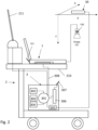
- Figure 2 shows a diagram of an embodiment of a cart on which a tracking and optionally image processing unit is mounted and on which an ultrasound imaging device can be secured to a support for it, while a wireless communication and/or a wired connection ca be activated between the tracking and optionally imaging processing unit and the ultrasound imaging device wearable and/or portable device.
- the cart 2 carry the processing unit 3 of a tracking system.
- a support table 210 is configured in such a way that an ultrasound imaging device 1 can be releasably, mechanically secured to it.
- the cart 12 may further be provided with a dedicated display 211 which is controlled by the processing unit 2 of the tracking system but which display 211 could also be connected, alternatively as a second display to the ultrasound imaging device 1.
- the probe 101 is provided with one or more tags and/or markers summarized schematically by the dot numbered with 130.
- a detector 30 scans a certain space in which also the target body is placed and detects the tag or tags and or the marker or markers 130 on the probe.
- the detection signals from the detector 30 are fed to a processing section 305 of the processing unit 2 of the tracking system.
- the signals form the detector are processed for extracting positional and/or orientation data of the probe 101 as it is displaced along the target body during an imaging session.
- the reference coordinate system in relation to which the data from the detector 30 provides position and/or orientation data of the probe is indicated schematically by the coordinate system spanned by the vectors x, y and z.
- the ultrasound imaging device and the tracking system, and in particular the processing unit 3 of the tracking system need to exchange data for combining the image data acquired by the probe and the position and/or orientation which the probe had during the acquisition of the said image data so that a clear position in space of the slice and/or of a 3D-sector acquired by the probe can be obtained in reference to the position and/or orientation of the target body.
- the processing unit 3 and the ultrasound device are provided both with a so-called short range communication unit indicated respectively with 129 in figure 1 and with 306 in figure 2 .
- Antennas respectively 131 on the ultrasound device and 307 on the processing unit 3 provides for the said wireless communication.
- the ultrasound device 1 and the processing unit 3 of the tracking system may also be connected by a wired connection as indicated with numeral 308.
- the said wired connection is only used for connection the ultrasound imaging device 1 to a electric power source for energizing the said ultrasound imaging device 1 while it is secured to the cart and/or for charging a battery provided in the ultrasound imaging system.
- the wired connection can also provide cables for connecting the ultrasound device 1 to the processing unit 3 by means of communication units operating according to wired network communication protocols such as for example network management protocols and/or network communication protocols and/or network security protocols like for example:
- the processing unit of the tracking system ma by a generic processing hardware, having a memory in which a program is stored which when executed by the said generic processing hardware comprises the instructions for the processor to carry out the operating steps for processing the data provided by the detector and calculating the probe positional and/or orientation data.
- processing unit of the tracking system comprises a user interface for inputting data and/or commands and/or for selecting optional operations.
- examples of the said user interfaces may comprise in any combination one or more of the following devices: a display, such as the display 211, a keyboard, a mouse or similar pointing and selection devices, a microphone, a loudspeaker, a video or photo camera.
- Some of the above interfaces may be integrated in a combination of a touch-screen display and a software controlling the said touch-screen for carrying out the functions of different interface types, such as for example the functions of the display, of the keyboard and of the pointing and selection device.
- a memory 303 is provided for saving the above disclosed software programs which comprises the instructions for carrying out the tracking functions.
- processing unit 3 of the tracking system may be also configured to execute image processing tools on the image data and/or also on the positional and orientation data of the probe and thus of the image slices or space sectors acquired by it.
- This kind of processing tools may be selected by the user thanks to the input means 302 and launched by desire.
- An electric power source such as a rechargeable accumulator or battery 304 provides for energizing the processing unit 3 and through it also the ultrasound imaging device 1.
- one or more optical cameras cover a certain field of view and determines the position and or the orientation of the probe within the said field of view by carrying out image recognition processing of the image of the probe acquired by the said one or more cameras.
- the support 210 for the ultrasound imaging device 1 and the ultrasound imaging device might be provided with mechanical connectors which secure the ultrasound imaging device 1 to the support 210 in a releasable way and/or separated connectors for generating an electric connection between lines outside the ultrasound imaging device 1 and inside it.
- the said connectors can be separated one form the other or can be combined in order to generate at the same time a mechanical releasable connection and an electric releasable connection.
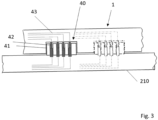
- FIG. 3 An example thereof is shown schematically in figure 3 .
- the example of figure 3 relates to a combined mechanical and electric connector assembly the case of the ultrasound imaging device 1 has one of the two connector elements of the connector assembly 40.
- This connector element comprises at least one slot 41 in which male contact electrodes 42 are positioned at a distance one from the other and from the peripheral walls of the slot 41. Further similar slots 41 can be provided on the case of the imaging device 1 as indicated by the one illustrated with discontinuous lines.
- the electrodes 41 are male in this case, but could also have alternatively a female configuration.
- Each electrode 42 is connected to an electric conductor 43 leading to a certain operative section of the ultrasound imaging device electronics here not shown in detail and disclosed in the high level diagram of figure 1 .
- one of the lines 43 could connect to the power supply 111, another to the sequence controller 110 or to the CPU 112 and further lines to other units such as for example a network communication unit operating by wired connection according to one or more of the previously disclosed network communication protocols.
- the other connector element 44 is provided on the support 210 of the cart provided for the ultrasound imaging device 1 and comprises a male element which has a shape and dimensions corresponding to the one of the slot 41 so that a mechanical joint by friction can be obtained between the two connector elements 41 and 44.
- the connector element 44 on the support 210 is provided with an electrode 45 which is placed in such geometrical relation to the peripheral sides of the connector element 44 that when the connector element 44 is engaged in the connector element 41 each or at leas some of the electrodes 45 comes into contact with a corresponding electrode 42 of the connector element 40 thereby generating an electric conductive connection between the said electrodes.
- Each electrode 45 is also connected to an electric conductor line 46.
- the liens 46 may be connected on the other side to different units of the processing unit 3 of the tracking system such as one or more memories, the processor 301, a communication unit operating by means of wired connection such as a network communication unit operating according to one or more of the above mentioned network communication protocols or other units.
- Wired network communication between the tracking system and the ultrasound imaging device may be useful for enhancing the processing speed and/or for example in an environment in which a high number of wireless communication is carried out between several different devices
- Figure 4 shows a possible embodiment of the method for carrying out probe tracking processes with a system according to the present invention and particularly to the above disclosed embodiments.
- Step 400 provides for positioning the ultrasound imaging device 1 near the cart 2 and not necessarily on the support 210 of the cart 2 either freely or in a secured manner to the said support 210.
- the distance between cart 2 and ultrasound imaging device must be within the limits of the range for providing a communication link of the short range communication system used by the ultrasound imaging device 1 and the cart 2 or the processing unit 3 of the tracking system.
- the routine for selecting a connection to the processing unit 3 of the tracking device is carried out at 401.
- the user might select also the kind of communication protocol to be used for connecting the imaging device 1 to the processing unit 3 of the tracking system.
- Connection routine might request that steps has to be executed at the ultrasound imaging device 1 only, at the processing unit 3 of the tracking system only or at both imaging device 1 and processing unit 3 depending on the kind of communication protocol used.
- a control is carried out if the communication link is active and at step 403 if the communication link is not active the steps 401 and 402 for connecting the ultrasound imaging device 1 to the processing unit 3 of the tracking system and/or to the cart 2 are repeated.
- the ultrasound imaging device may be used for image acquisition and contemporary probe tracking in relation to its position and to its orientation as indicated by 404 .
- a check can be carried out for verifying if the tracking of the probe is active and works properly. If not the tracking system and ultrasound device setup has to be repeated as indicated by step 406.
- different processing steps of the said image data and the said positional and orientation data of the probe may be carried out such as simply univocally correlating the said data and then saving the said data or to provide the said data to a further processing tool executed entirely and/or partially by the processing unit 3 of the tracking system and/or also entirely and/or partially by the ultrasound imaging device 1.
- a corresponding image processing tool can be launched for being executed entirely and/or partially by the processing unit 3 of the tracking system and/or also entirely and/or partially by the ultrasound imaging device 1. If not, the process is terminated as indicated at step 410 and the obtained data may be stored and/or displayed and or otherwise used.
- the communication unit for the transmission and reception communication between the processing unit of the tracking system and the ultrasound imaging device may be resident on the cart as a separate and physically independent unit relatively to the ultrasound imaging device 1 and the tracking system, particularly the processing unit of the tracking system.
- the said communication unit might be connected to the processing unit 3 of the tracking system by means of a wired hardware connection to the said processing unit 3 of the tracking system so that it comes under the control of the processor 301 of the said processing unit 3 or it micht operate as a sort of bridge or intermediate communication unit whi9ch connects wirelessly by means of a short range communication protocol with the processing unit 3 of the tracking system and with the ultrasound imaging device, so that different tracking systems and different ultrasound imaging devices also of different producers may be associated to a same cart without the need of being bounded to a specific ultrasound imaging device 1 and to a specific tracking system.
Landscapes
- Health & Medical Sciences (AREA)
- Life Sciences & Earth Sciences (AREA)
- Engineering & Computer Science (AREA)
- Heart & Thoracic Surgery (AREA)
- Molecular Biology (AREA)
- Biophysics (AREA)
- Nuclear Medicine, Radiotherapy & Molecular Imaging (AREA)
- Pathology (AREA)
- Radiology & Medical Imaging (AREA)
- Biomedical Technology (AREA)
- Veterinary Medicine (AREA)
- Medical Informatics (AREA)
- Physics & Mathematics (AREA)
- Surgery (AREA)
- Animal Behavior & Ethology (AREA)
- General Health & Medical Sciences (AREA)
- Public Health (AREA)
- Computer Networks & Wireless Communication (AREA)
- Computer Vision & Pattern Recognition (AREA)
- Gynecology & Obstetrics (AREA)
- Ultra Sonic Daignosis Equipment (AREA)
Priority Applications (2)
| Application Number | Priority Date | Filing Date | Title |
|---|---|---|---|
| EP23151919.0A EP4403113A1 (de) | 2023-01-17 | 2023-01-17 | System und verfahren zur erfassung von diagnosebildern mittels ultraschall |
| US18/407,510 US20240237968A1 (en) | 2023-01-17 | 2024-01-09 | System and method for acquiring diagnostic images by ultrasounds |
Applications Claiming Priority (1)
| Application Number | Priority Date | Filing Date | Title |
|---|---|---|---|
| EP23151919.0A EP4403113A1 (de) | 2023-01-17 | 2023-01-17 | System und verfahren zur erfassung von diagnosebildern mittels ultraschall |
Publications (1)
| Publication Number | Publication Date |
|---|---|
| EP4403113A1 true EP4403113A1 (de) | 2024-07-24 |
Family
ID=84982122
Family Applications (1)
| Application Number | Title | Priority Date | Filing Date |
|---|---|---|---|
| EP23151919.0A Pending EP4403113A1 (de) | 2023-01-17 | 2023-01-17 | System und verfahren zur erfassung von diagnosebildern mittels ultraschall |
Country Status (2)
| Country | Link |
|---|---|
| US (1) | US20240237968A1 (de) |
| EP (1) | EP4403113A1 (de) |
Citations (7)
| Publication number | Priority date | Publication date | Assignee | Title |
|---|---|---|---|---|
| EP1467317A1 (de) | 2003-04-11 | 2004-10-13 | MedCom Gesellschaft für medizinische Bildverarbeitung mbH | Kombinieren von ersten und zweiten Bilddaten eines Objekts |
| EP2404551A1 (de) | 2010-07-07 | 2012-01-11 | Esaote S.p.A. | Verfahren und Bildgebungsvorrichtung um die anatomische Platzierung von metallischen Objekten zu beobachten |
| EP2998932A1 (de) | 2014-09-16 | 2016-03-23 | Esaote S.p.A. | Verfahren und vorrichtung zur erfassung von ultraschallbildern und zur fusion solcher bilder mit bereits erfassten bilder |
| EP3689247A1 (de) | 2019-01-30 | 2020-08-05 | MedCom GmbH | Ultraschallbildgebungsverfahren und ultraschallbildgebungssystem zur durchführung des verfahrens |
| US20200245973A1 (en) * | 2014-11-18 | 2020-08-06 | C. R. Bard, Inc. | Ultrasound imaging system having automatic image presentation |
| US20210322148A1 (en) * | 2018-08-28 | 2021-10-21 | Smith & Nephew, Inc. | Robotic assisted ligament graft placement and tensioning |
| EP4088664A1 (de) * | 2021-05-13 | 2022-11-16 | Esaote S.p.A. | Multi-user-system zur aufnahme, erzeugung und verarbeitung von ultraschallbildern |
-
2023
- 2023-01-17 EP EP23151919.0A patent/EP4403113A1/de active Pending
-
2024
- 2024-01-09 US US18/407,510 patent/US20240237968A1/en active Pending
Patent Citations (7)
| Publication number | Priority date | Publication date | Assignee | Title |
|---|---|---|---|---|
| EP1467317A1 (de) | 2003-04-11 | 2004-10-13 | MedCom Gesellschaft für medizinische Bildverarbeitung mbH | Kombinieren von ersten und zweiten Bilddaten eines Objekts |
| EP2404551A1 (de) | 2010-07-07 | 2012-01-11 | Esaote S.p.A. | Verfahren und Bildgebungsvorrichtung um die anatomische Platzierung von metallischen Objekten zu beobachten |
| EP2998932A1 (de) | 2014-09-16 | 2016-03-23 | Esaote S.p.A. | Verfahren und vorrichtung zur erfassung von ultraschallbildern und zur fusion solcher bilder mit bereits erfassten bilder |
| US20200245973A1 (en) * | 2014-11-18 | 2020-08-06 | C. R. Bard, Inc. | Ultrasound imaging system having automatic image presentation |
| US20210322148A1 (en) * | 2018-08-28 | 2021-10-21 | Smith & Nephew, Inc. | Robotic assisted ligament graft placement and tensioning |
| EP3689247A1 (de) | 2019-01-30 | 2020-08-05 | MedCom GmbH | Ultraschallbildgebungsverfahren und ultraschallbildgebungssystem zur durchführung des verfahrens |
| EP4088664A1 (de) * | 2021-05-13 | 2022-11-16 | Esaote S.p.A. | Multi-user-system zur aufnahme, erzeugung und verarbeitung von ultraschallbildern |
Non-Patent Citations (1)
| Title |
|---|
| LAURENCE MERCIERTHOMAS LANGPFRANK LINDSETHLOUIS D COLLINS: "A review of calibration techniques for freehand 3-D ultrasound systems", ULTRASOUND MED BIOL, vol. 31, no. 2, February 2005 (2005-02-01), pages 143 - 65 |
Also Published As
| Publication number | Publication date |
|---|---|
| US20240237968A1 (en) | 2024-07-18 |
Similar Documents
| Publication | Publication Date | Title |
|---|---|---|
| US11730447B2 (en) | Haptic feedback for ultrasound image acquisition | |
| US11986355B2 (en) | 3D ultrasound imaging system | |
| US11642096B2 (en) | Method for postural independent location of targets in diagnostic images acquired by multimodal acquisitions and system for carrying out the method | |
| US11653897B2 (en) | Ultrasonic diagnostic apparatus, scan support method, and medical image processing apparatus | |
| US11995818B2 (en) | Synchronized surface and internal tumor detection | |
| KR101182880B1 (ko) | 영상 지시자를 제공하는 초음파 시스템 및 방법 | |
| JP6018411B2 (ja) | 画像ガイド下手技のための超音波撮像システム | |
| US11109839B2 (en) | Imaging systems and methods for positioning a 3D ultrasound volume in a desired orientation | |
| US9675321B2 (en) | Ultrasonographic systems and methods for examining and treating spinal conditions | |
| JP6833533B2 (ja) | 超音波診断装置および超音波診断支援プログラム | |
| JP6956483B2 (ja) | 超音波診断装置、及び走査支援プログラム | |
| JPWO2010055816A1 (ja) | 超音波診断装置、超音波診断装置の規格画像データ生成方法 | |
| KR20150131566A (ko) | 초음파 진단장치 및 그에 따른 초음파 진단 방법 | |
| JP6720001B2 (ja) | 超音波診断装置、及び医用画像処理装置 | |
| TW202110404A (zh) | 超音波影像系統 | |
| US20130018264A1 (en) | Method and system for ultrasound imaging | |
| EP3381373A1 (de) | Ultraschalldiagnosevorrichtung und verfahren zur steuerung davon | |
| JP5572376B2 (ja) | 超音波ドッキングポートを含む医療用イメージングシステム及び方法 | |
| EP4403113A1 (de) | System und verfahren zur erfassung von diagnosebildern mittels ultraschall | |
| JP2008289548A (ja) | 超音波診断装置及び診断パラメータ計測装置 | |
| KR100875620B1 (ko) | 초음파 영상 시스템 및 방법 | |
| JP2006296464A (ja) | 超音波診断装置 | |
| TW202322766A (zh) | 超音波影像系統 |
Legal Events
| Date | Code | Title | Description |
|---|---|---|---|
| PUAI | Public reference made under article 153(3) epc to a published international application that has entered the european phase |
Free format text: ORIGINAL CODE: 0009012 |
|
| STAA | Information on the status of an ep patent application or granted ep patent |
Free format text: STATUS: THE APPLICATION HAS BEEN PUBLISHED |
|
| AK | Designated contracting states |
Kind code of ref document: A1 Designated state(s): AL AT BE BG CH CY CZ DE DK EE ES FI FR GB GR HR HU IE IS IT LI LT LU LV MC ME MK MT NL NO PL PT RO RS SE SI SK SM TR |
|
| STAA | Information on the status of an ep patent application or granted ep patent |
Free format text: STATUS: REQUEST FOR EXAMINATION WAS MADE |
|
| 17P | Request for examination filed |
Effective date: 20250120 |
|
| P01 | Opt-out of the competence of the unified patent court (upc) registered |
Free format text: CASE NUMBER: APP_6434/2025 Effective date: 20250207 |