EP3972043B1 - Terminal for secondary battery and secondary battery provided with the terminal - Google Patents
Terminal for secondary battery and secondary battery provided with the terminal Download PDFInfo
- Publication number
- EP3972043B1 EP3972043B1 EP21193349.4A EP21193349A EP3972043B1 EP 3972043 B1 EP3972043 B1 EP 3972043B1 EP 21193349 A EP21193349 A EP 21193349A EP 3972043 B1 EP3972043 B1 EP 3972043B1
- Authority
- EP
- European Patent Office
- Prior art keywords
- terminal
- negative electrode
- positive electrode
- constituted
- secondary battery
- Prior art date
- Legal status (The legal status is an assumption and is not a legal conclusion. Google has not performed a legal analysis and makes no representation as to the accuracy of the status listed.)
- Active
Links
Images


Classifications
-
- H—ELECTRICITY
- H01—ELECTRIC ELEMENTS
- H01M—PROCESSES OR MEANS, e.g. BATTERIES, FOR THE DIRECT CONVERSION OF CHEMICAL ENERGY INTO ELECTRICAL ENERGY
- H01M50/00—Constructional details or processes of manufacture of the non-active parts of electrochemical cells other than fuel cells, e.g. hybrid cells
- H01M50/50—Current conducting connections for cells or batteries
- H01M50/543—Terminals
- H01M50/552—Terminals characterised by their shape
-
- H—ELECTRICITY
- H01—ELECTRIC ELEMENTS
- H01M—PROCESSES OR MEANS, e.g. BATTERIES, FOR THE DIRECT CONVERSION OF CHEMICAL ENERGY INTO ELECTRICAL ENERGY
- H01M50/00—Constructional details or processes of manufacture of the non-active parts of electrochemical cells other than fuel cells, e.g. hybrid cells
- H01M50/50—Current conducting connections for cells or batteries
- H01M50/543—Terminals
- H01M50/564—Terminals characterised by their manufacturing process
- H01M50/566—Terminals characterised by their manufacturing process by welding, soldering or brazing
-
- H—ELECTRICITY
- H01—ELECTRIC ELEMENTS
- H01M—PROCESSES OR MEANS, e.g. BATTERIES, FOR THE DIRECT CONVERSION OF CHEMICAL ENERGY INTO ELECTRICAL ENERGY
- H01M50/00—Constructional details or processes of manufacture of the non-active parts of electrochemical cells other than fuel cells, e.g. hybrid cells
- H01M50/50—Current conducting connections for cells or batteries
- H01M50/543—Terminals
- H01M50/552—Terminals characterised by their shape
- H01M50/553—Terminals adapted for prismatic, pouch or rectangular cells
-
- H—ELECTRICITY
- H01—ELECTRIC ELEMENTS
- H01M—PROCESSES OR MEANS, e.g. BATTERIES, FOR THE DIRECT CONVERSION OF CHEMICAL ENERGY INTO ELECTRICAL ENERGY
- H01M50/00—Constructional details or processes of manufacture of the non-active parts of electrochemical cells other than fuel cells, e.g. hybrid cells
- H01M50/50—Current conducting connections for cells or batteries
- H01M50/543—Terminals
- H01M50/562—Terminals characterised by the material
-
- B—PERFORMING OPERATIONS; TRANSPORTING
- B23—MACHINE TOOLS; METAL-WORKING NOT OTHERWISE PROVIDED FOR
- B23K—SOLDERING OR UNSOLDERING; WELDING; CLADDING OR PLATING BY SOLDERING OR WELDING; CUTTING BY APPLYING HEAT LOCALLY, e.g. FLAME CUTTING; WORKING BY LASER BEAM
- B23K20/00—Non-electric welding by applying impact or other pressure, with or without the application of heat, e.g. cladding or plating
- B23K20/10—Non-electric welding by applying impact or other pressure, with or without the application of heat, e.g. cladding or plating making use of vibrations, e.g. ultrasonic welding
-
- B—PERFORMING OPERATIONS; TRANSPORTING
- B23—MACHINE TOOLS; METAL-WORKING NOT OTHERWISE PROVIDED FOR
- B23K—SOLDERING OR UNSOLDERING; WELDING; CLADDING OR PLATING BY SOLDERING OR WELDING; CUTTING BY APPLYING HEAT LOCALLY, e.g. FLAME CUTTING; WORKING BY LASER BEAM
- B23K20/00—Non-electric welding by applying impact or other pressure, with or without the application of heat, e.g. cladding or plating
- B23K20/22—Non-electric welding by applying impact or other pressure, with or without the application of heat, e.g. cladding or plating taking account of the properties of the materials to be welded
- B23K20/233—Non-electric welding by applying impact or other pressure, with or without the application of heat, e.g. cladding or plating taking account of the properties of the materials to be welded without ferrous layer
- B23K20/2333—Non-electric welding by applying impact or other pressure, with or without the application of heat, e.g. cladding or plating taking account of the properties of the materials to be welded without ferrous layer one layer being aluminium, magnesium or beryllium
-
- H—ELECTRICITY
- H01—ELECTRIC ELEMENTS
- H01M—PROCESSES OR MEANS, e.g. BATTERIES, FOR THE DIRECT CONVERSION OF CHEMICAL ENERGY INTO ELECTRICAL ENERGY
- H01M50/00—Constructional details or processes of manufacture of the non-active parts of electrochemical cells other than fuel cells, e.g. hybrid cells
- H01M50/10—Primary casings; Jackets or wrappings
- H01M50/102—Primary casings; Jackets or wrappings characterised by their shape or physical structure
- H01M50/103—Primary casings; Jackets or wrappings characterised by their shape or physical structure prismatic or rectangular
-
- H—ELECTRICITY
- H01—ELECTRIC ELEMENTS
- H01M—PROCESSES OR MEANS, e.g. BATTERIES, FOR THE DIRECT CONVERSION OF CHEMICAL ENERGY INTO ELECTRICAL ENERGY
- H01M50/00—Constructional details or processes of manufacture of the non-active parts of electrochemical cells other than fuel cells, e.g. hybrid cells
- H01M50/20—Mountings; Secondary casings or frames; Racks, modules or packs; Suspension devices; Shock absorbers; Transport or carrying devices; Holders
- H01M50/204—Racks, modules or packs for multiple batteries or multiple cells
- H01M50/207—Racks, modules or packs for multiple batteries or multiple cells characterised by their shape
- H01M50/209—Racks, modules or packs for multiple batteries or multiple cells characterised by their shape adapted for prismatic or rectangular cells
-
- H—ELECTRICITY
- H01—ELECTRIC ELEMENTS
- H01M—PROCESSES OR MEANS, e.g. BATTERIES, FOR THE DIRECT CONVERSION OF CHEMICAL ENERGY INTO ELECTRICAL ENERGY
- H01M50/00—Constructional details or processes of manufacture of the non-active parts of electrochemical cells other than fuel cells, e.g. hybrid cells
- H01M50/50—Current conducting connections for cells or batteries
- H01M50/502—Interconnectors for connecting terminals of adjacent batteries; Interconnectors for connecting cells outside a battery casing
- H01M50/507—Interconnectors for connecting terminals of adjacent batteries; Interconnectors for connecting cells outside a battery casing comprising an arrangement of two or more busbars within a container structure, e.g. busbar modules
-
- H—ELECTRICITY
- H01—ELECTRIC ELEMENTS
- H01M—PROCESSES OR MEANS, e.g. BATTERIES, FOR THE DIRECT CONVERSION OF CHEMICAL ENERGY INTO ELECTRICAL ENERGY
- H01M50/00—Constructional details or processes of manufacture of the non-active parts of electrochemical cells other than fuel cells, e.g. hybrid cells
- H01M50/50—Current conducting connections for cells or batteries
- H01M50/502—Interconnectors for connecting terminals of adjacent batteries; Interconnectors for connecting cells outside a battery casing
- H01M50/509—Interconnectors for connecting terminals of adjacent batteries; Interconnectors for connecting cells outside a battery casing characterised by the type of connection, e.g. mixed connections
- H01M50/512—Connection only in parallel
-
- H—ELECTRICITY
- H01—ELECTRIC ELEMENTS
- H01M—PROCESSES OR MEANS, e.g. BATTERIES, FOR THE DIRECT CONVERSION OF CHEMICAL ENERGY INTO ELECTRICAL ENERGY
- H01M50/00—Constructional details or processes of manufacture of the non-active parts of electrochemical cells other than fuel cells, e.g. hybrid cells
- H01M50/50—Current conducting connections for cells or batteries
- H01M50/502—Interconnectors for connecting terminals of adjacent batteries; Interconnectors for connecting cells outside a battery casing
- H01M50/521—Interconnectors for connecting terminals of adjacent batteries; Interconnectors for connecting cells outside a battery casing characterised by the material
- H01M50/522—Inorganic material
-
- H—ELECTRICITY
- H01—ELECTRIC ELEMENTS
- H01M—PROCESSES OR MEANS, e.g. BATTERIES, FOR THE DIRECT CONVERSION OF CHEMICAL ENERGY INTO ELECTRICAL ENERGY
- H01M50/00—Constructional details or processes of manufacture of the non-active parts of electrochemical cells other than fuel cells, e.g. hybrid cells
- H01M50/50—Current conducting connections for cells or batteries
- H01M50/543—Terminals
- H01M50/552—Terminals characterised by their shape
- H01M50/553—Terminals adapted for prismatic, pouch or rectangular cells
- H01M50/557—Plate-shaped terminals
-
- H—ELECTRICITY
- H01—ELECTRIC ELEMENTS
- H01M—PROCESSES OR MEANS, e.g. BATTERIES, FOR THE DIRECT CONVERSION OF CHEMICAL ENERGY INTO ELECTRICAL ENERGY
- H01M50/00—Constructional details or processes of manufacture of the non-active parts of electrochemical cells other than fuel cells, e.g. hybrid cells
- H01M50/50—Current conducting connections for cells or batteries
- H01M50/543—Terminals
- H01M50/564—Terminals characterised by their manufacturing process
- H01M50/567—Terminals characterised by their manufacturing process by fixing means, e.g. screws, rivets or bolts
-
- B—PERFORMING OPERATIONS; TRANSPORTING
- B23—MACHINE TOOLS; METAL-WORKING NOT OTHERWISE PROVIDED FOR
- B23K—SOLDERING OR UNSOLDERING; WELDING; CLADDING OR PLATING BY SOLDERING OR WELDING; CUTTING BY APPLYING HEAT LOCALLY, e.g. FLAME CUTTING; WORKING BY LASER BEAM
- B23K2101/00—Articles made by soldering, welding or cutting
- B23K2101/36—Electric or electronic devices
-
- B—PERFORMING OPERATIONS; TRANSPORTING
- B23—MACHINE TOOLS; METAL-WORKING NOT OTHERWISE PROVIDED FOR
- B23K—SOLDERING OR UNSOLDERING; WELDING; CLADDING OR PLATING BY SOLDERING OR WELDING; CUTTING BY APPLYING HEAT LOCALLY, e.g. FLAME CUTTING; WORKING BY LASER BEAM
- B23K2103/00—Materials to be soldered, welded or cut
- B23K2103/08—Non-ferrous metals or alloys
- B23K2103/10—Aluminium or alloys thereof
-
- B—PERFORMING OPERATIONS; TRANSPORTING
- B23—MACHINE TOOLS; METAL-WORKING NOT OTHERWISE PROVIDED FOR
- B23K—SOLDERING OR UNSOLDERING; WELDING; CLADDING OR PLATING BY SOLDERING OR WELDING; CUTTING BY APPLYING HEAT LOCALLY, e.g. FLAME CUTTING; WORKING BY LASER BEAM
- B23K2103/00—Materials to be soldered, welded or cut
- B23K2103/08—Non-ferrous metals or alloys
- B23K2103/12—Copper or alloys thereof
-
- H—ELECTRICITY
- H01—ELECTRIC ELEMENTS
- H01M—PROCESSES OR MEANS, e.g. BATTERIES, FOR THE DIRECT CONVERSION OF CHEMICAL ENERGY INTO ELECTRICAL ENERGY
- H01M10/00—Secondary cells; Manufacture thereof
- H01M10/05—Accumulators with non-aqueous electrolyte
- H01M10/052—Li-accumulators
- H01M10/0525—Rocking-chair batteries, i.e. batteries with lithium insertion or intercalation in both electrodes; Lithium-ion batteries
-
- Y—GENERAL TAGGING OF NEW TECHNOLOGICAL DEVELOPMENTS; GENERAL TAGGING OF CROSS-SECTIONAL TECHNOLOGIES SPANNING OVER SEVERAL SECTIONS OF THE IPC; TECHNICAL SUBJECTS COVERED BY FORMER USPC CROSS-REFERENCE ART COLLECTIONS [XRACs] AND DIGESTS
- Y02—TECHNOLOGIES OR APPLICATIONS FOR MITIGATION OR ADAPTATION AGAINST CLIMATE CHANGE
- Y02E—REDUCTION OF GREENHOUSE GAS [GHG] EMISSIONS, RELATED TO ENERGY GENERATION, TRANSMISSION OR DISTRIBUTION
- Y02E60/00—Enabling technologies; Technologies with a potential or indirect contribution to GHG emissions mitigation
- Y02E60/10—Energy storage using batteries
Definitions
- the present disclosure relates to a terminal of a secondary battery. Specifically, the present disclosure relates to a terminal which is arranged at a prescribed position in a secondary battery and which enables conduction from inside to outside of the cell, and to a secondary battery using the terminal.
- Secondary batteries such as lithium-ion secondary batteries are capable of producing high energy density despite being lightweight and are therefore widely used as portable power supplies of personal computers, portable terminals, and the like as well as vehicle-mounted power supplies of EVs (electrical vehicles), HVs (hybrid vehicles), PHVs (plug-in hybrid vehicles), and the like.
- EVs electrical vehicles
- HVs hybrid vehicles
- PHVs plug-in hybrid vehicles
- assembled batteries in which a plurality of secondary batteries (cells) are electrically connected to each other are preferably used.
- an assembled battery is constructed by respectively electrically connecting positive electrode terminals and negative electrode terminals of a plurality of cells via busbars.
- busbar to the positive electrode terminal and the negative electrode terminal of a cell
- a metal that constitutes the busbar and a metal that constitutes the positive electrode terminal and the negative electrode terminal differ from each other, it is difficult to perform the welding in an appropriate manner due to differences in thermal conductivity and melting points.
- water or the like comes into contact with a boundary between dissimilar metals, electricity is generated and corrosive deterioration of the metals may occur.
- Japanese Patent Application JP 2011-124024 A discloses an assembled battery using a positive electrode terminal constituted by dissimilar metals so that a metal constituting a busbar and a metal constituting a busbar-welding portion of the positive electrode terminal are made identical to each other.
- the positive electrode terminal is made up of a base portion that is mainly constituted by aluminum and a positive electrode external terminal that is mainly constituted by copper, and the base portion and the positive electrode external terminal are joined to each other by ultrasonic joining and swaging. Accordingly, compatibility, when welding the busbar made of copper and the positive electrode external terminal mainly constituted by copper to each other, can be improved.
- Japanese Patent Application JP 2016-18675 A discloses a secondary battery in which a metal member constituted by a same metal as a metal constituting a busbar is joined to an external terminal by ultrasonic joining.
- a battery and a method for manufacturing the same is furthermore known from US 2019/0273240 A1 , in which an external terminal and a seat portion of an internal terminal are solid-state welded together by causing the external terminal or the internal terminal to vibrate while detaching an insulator from the external terminal in at least a region surrounding the seat portion and pressing the external terminal against the seat portion.
- the present disclosure has been made in consideration of the circumstances described above, and a main object thereof is to provide a terminal which constitutes any of positive and negative electrodes of a secondary battery and which enables welding with an external member such as a busbar to be performed without requiring surface treatment of a metal portion having been pressure-welded by ultrasonic welding.
- another object of the present disclosure is to provide a secondary battery and an assembled battery provided with the terminal.
- a terminal disclosed herein is a terminal constituting any of positive and negative electrodes of a secondary battery and includes a plate-like metallic first member and a metallic second member which is ultrasonically welded to one plate surface of the first member.
- a recessed portion is formed on a surface on an opposite side to the surface, to which the second member is welded, of the first member, and ultrasonic welding between the first member and the second member is realized in the recessed portion.
- a terminal is provided which enables welding of an external member such as a busbar to be performed on a plate surface having a recessed portion of the first member without requiring surface treatment.
- the first member and the second member are constituted by metals that differ from each other.
- a terminal is provided which enables welding between the first member and an external member such as a busbar and joining between the second member and an internal terminal electrically connected to an electrode body to be preferably performed.
- a terminal which enables welding of an external member such as a busbar to be performed in a state where welding residue created when performing the ultrasonic welding is present in the recessed portion.
- the first member is constituted by aluminum or an alloy having aluminum as a main component
- the second member is constituted by copper or an alloy having copper as a main component.
- a terminal is provided which enables joining between an external member such as a busbar that is constituted by aluminum or an alloy having aluminum as a main component and the first member and joining between a negative electrode internal terminal which is constituted by copper or an alloy having copper as a main component and which is electrically connected to a negative electrode and the second member to be preferably performed.
- a secondary battery disclosed herein includes: an electrode body including a positive electrode and a negative electrode; a battery case housing therein the electrode body; and a positive electrode terminal and a negative electrode terminal electrically connected to the positive electrode and the negative electrode of the electrode body, respectively, wherein at least one of the positive electrode terminal and the negative electrode terminal is constituted by the terminal disclosed herein.
- a secondary battery which enables preferable joining between the positive and negative electrode terminals and an external member to be realized.
- an assembled battery disclosed herein is constructed by aligning a plurality of cells that are electrically connected to each other, wherein the secondary battery disclosed herein is used as the plurality of cells.
- an assembled battery which enables an electrical connection between terminals and an external member such as a busbar to be preferably performed.
- a positive electrode terminal of a single cell and a negative electrode terminal of another single cell are respectively electrically connected by a predetermined busbar, the terminal disclosed herein is used as one terminal of the positive electrode terminal of the single cell and the negative electrode terminal of the other single cell, and the busbar is formed of a same metal as a metal that constitutes the first member of the terminal.
- an assembled battery which enables welding between the busbar and the positive and negative electrode terminals to be preferably realized.
- a method of manufacturing the terminal disclosed herein includes the steps of: preparing a plate-like metallic first member and a metallic second member; and joining the second member to one plate surface of the first member by ultrasonic welding, wherein a recessed portion is formed on a surface on an opposite side to the surface, to which the second member is welded, of the first member, and the ultrasonic welding is executed in the recessed portion.
- burrs that may be created by ultrasonic welding can be kept inside the recessed portion and a terminal that does not require surface treatment after the ultrasonic welding can be provided.
- the first member and the second member are constituted by metals that differ from each other.
- a terminal can be manufactured which enables welding between the first member and an external member such as a busbar and welding between the second member and an internal terminal electrically connected to an electrode body to be preferably performed.
- the first member is constituted by aluminum or an alloy having aluminum as a main component
- the second member is constituted by copper or an alloy having copper as a main component.
- a terminal can be manufactured which enables joining between an external member such as a busbar that is constituted by aluminum or an alloy having aluminum as a main component and the first member and joining between a negative electrode internal terminal which is constituted by copper or an alloy having copper as a main component and which is electrically connected to a negative electrode and the second member to be preferably performed.
- an external member such as a busbar that is constituted by aluminum or an alloy having aluminum as a main component and the first member
- a negative electrode internal terminal which is constituted by copper or an alloy having copper as a main component and which is electrically connected to a negative electrode and the second member to be preferably performed.
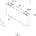
- a reference character X denotes a width direction (of a battery)
- a reference character Y denotes a thickness direction
- a reference character Z denotes a height direction.
- such directions are directions determined for the sake of illustration and are not intended to limit modes of installation of batteries.
- a “secondary battery” refers to repetitively chargeable/dischargeable power storage devices in general and encompasses so-called storage batteries (in other words, chemical batteries) such as a lithium-ion secondary battery, a nickel hydride battery, and a nickel-cadmium battery as well as capacitors (in other words, physical batteries) such as an electrical double layer capacitor.
- a “lithium-ion secondary battery” refers to a secondary battery using lithium ions as charge carriers in which charging and discharging are realized by the movement of charges accompanying lithium ions between a positive electrode and a negative electrode.
- FIG. 1 is a perspective view schematically showing a secondary battery according to the present embodiment.
- FIG. 3 is a partial breakaway view schematically showing the secondary battery according to the embodiment.
- a secondary battery 1 according to the present embodiment includes an electrode body 20, an electrolyte (not illustrated), a battery case 30, a positive electrode terminal 40, a negative electrode terminal 50, a gasket 60, and an insulator 62.
- the positive electrode terminal 40 includes a positive electrode internal terminal 42 and a positive electrode external terminal 44
- the negative electrode terminal 50 includes a negative electrode internal terminal 52 and a negative electrode external terminal 54.
- the secondary battery 1 including a terminal 70 disclosed herein as the negative electrode external terminal 54 will be illustrated as the present embodiment. However, this is simply one example and other examples include the secondary battery 1 including the terminal 70 disclosed herein as the positive electrode external terminal 44. A configuration of the terminal 70 will be described later.
- FIG. 2 is a perspective view schematically showing an assembled battery according to the present embodiment.
- the assembled battery 10 is constructed by aligning a plurality of secondary batteries (cells) 1 that are electrically connected to each other, wherein each cell is the secondary battery disclosed herein. Due to an alignment in which the cells 1 are inverted one by one, the positive electrode terminal 40 and the negative electrode terminal 50 are alternately arranged.
- a spacer 12 is inserted between the aligned cells 1.
- the spacer 12 is capable of functioning as heat radiating means for efficiently dissipating heat, length adjusting means, and the like.
- a pair of end plates (constraining plates) 17 is arranged at both ends of the aligned cells 1.
- a constraining beam member 18 is attached so as to bridge both end plates 17. Ends of the beam member 18 are fastened and fixed to the end plates 17 by screws 19. Accordingly, the plurality of cells 1 are constrained in an alignment direction of the cells 1 so that a constraint load is applied thereto.
- the assembled battery 10 includes, between two cells 1 arranged adjacent to each other, a busbar 14 which connects an external member joining portion of the positive electrode external terminal 44 of a single cell 1 and an external member joining portion of the negative electrode external terminal 54 of another single cell 1 to each other. Accordingly, a conductive path from the positive electrode internal terminal 42 of the single cell 1 to the negative electrode internal terminal 52 of the other single cell 1 is formed via the busbar 14 and the external terminals and the respective cells 1 are electrically connected in series.
- the busbar 14 is generally constituted by a metal with high conductivity of which examples include aluminum, copper, tin, nickel, and an alloy containing any of these metals as a main component.
- the terminal 70 configured as disclosed herein is used as either one terminal of the positive electrode terminal 40 (the positive electrode external terminal 44) of a single cell 1 and the negative electrode terminal 50 (the negative electrode external terminal 54) of another single cell 1 being connected by the busbar 14, and the busbar 14 is formed of a same metal as a metal that constitutes the first member 72 of the terminal 70. Due to the busbar 14 and the first member 72 being constituted by a same metal, welding can be strengthened and preferable conduction can be realized.
- the busbar 14, the external member joining portion of the positive electrode external terminal 44, and the external member joining portion of the negative electrode external terminal 54 are constituted by a same metal.
- the positive electrode external terminal 44 of a single cell is constituted by aluminum
- the negative electrode external terminal 54 of another single call is the terminal 70 structured as disclosed herein
- the first member 72 (refer to FIG. 5 ) of the terminal 70 is constituted by aluminum
- the busbar 14 is preferably constituted by aluminum. According to this configuration, welding between the busbar 14 and the positive electrode external terminal 44 and the negative electrode external terminal 54 is strengthened and more preferable conduction is realized. It should be noted that the above merely represents a preferable specific example and is not intended to limit metals that constitute the external terminals of the positive electrode and the negative electrode and the busbar.
- the battery case 30 is a container which houses the electrode body 20. As shown in FIG. 1 , the battery case 30 according to the present embodiment is a flat square container. However, the shape of the battery case 30 may be a box shape that is not a square (for example, a bottomed cylindrical box shape).
- the battery case 30 includes a square case main body 32 of which an upper surface is opened and a plate-shaped lid 34 which closes an opening portion of the case main body 32. As shown in FIG. 3 , the lid 34 is provided with a safety valve 36 that releases internal pressure inside the battery case 30 when the internal pressure rises to or exceeds a prescribed level.
- the lid 34 is provided with a terminal insertion hole 34a that enables the negative electrode external terminal 54 to be inserted and a terminal insertion hole 34b that enables the positive electrode external terminal 44 to be inserted.
- a metallic material with required strength is used and, for example, a lightweight metallic material with good thermal conductivity such as aluminum, stainless steel, or nickel-plated steel is used.
- the electrode body 20 is a power generation element housed inside the battery case 30 in a state of being covered by an insulating film (not illustrated) or the like.
- the electrode body 20 according to the present embodiment includes an elongated sheet-shaped positive electrode 21, an elongated sheet-shaped negative electrode 22, and an elongated sheet-shaped separator 23.
- the electrode body 20 is a wound electrode body in which the elongated sheet-shaped members described above are wound in layers. It should be noted that the structure of the electrode body is not particularly limited and various structures that may be adopted in a general sealed battery can be adopted.
- the electrode body may be a laminated electrode body in which a positive electrode and a negative electrode with rectangular sheet shapes are laminated via a separator.
- the positive electrode 21 includes a foil-shaped positive electrode current collector (for example, aluminum foil) and a positive electrode active material layer formed on a surface (preferably, both surfaces) of the positive electrode current collector.
- a positive electrode active material layer is not formed but a positive electrode connecting portion 21a is formed in which the positive electrode current collector is exposed.
- the positive electrode active material layer includes various materials such as a positive electrode active material, a binder, and a conductive material.
- materials included in the positive electrode active material layer materials that may be used in a conventional general secondary battery (for example, a lithium-ion secondary battery) can be used without any particular limitations, and since the materials included in the positive electrode active material layer do not limit the present disclosure, a detailed description thereof will be omitted.
- a conventional general secondary battery for example, a lithium-ion secondary battery
- the negative electrode 22 includes a foil-shaped negative electrode current collector (for example, copper foil) and a negative electrode active material layer formed on a surface (preferably, both surfaces) of the negative electrode current collector.
- a foil-shaped negative electrode current collector for example, copper foil
- a negative electrode active material layer formed on a surface (preferably, both surfaces) of the negative electrode current collector.
- the negative electrode active material layer is not formed but a negative electrode connecting portion 22a is formed in which the negative electrode current collector is exposed.
- the negative electrode active material layer also includes various materials such as a negative electrode active material, a binder, and the like.
- materials included in the negative electrode active material layer materials that may be used in a conventional general secondary battery can be similarly used without any particular limitations, and since the materials included in the negative electrode active material layer do not limit the present disclosure, a detailed description thereof will be omitted.
- the separator 23 is interposed between the positive electrode 21 and the negative electrode 22 and prevents the electrodes from coming into direct contact with each other.
- micropores are formed in plurality in the separator 23, and a configuration is adopted in which lithium ions move between the positive electrode 21 and the negative electrode 22 through these micropores.
- a resin sheet or the like having required heat resistance is used as the separator 23 since a separator that may be used in a conventional general secondary battery can be used as the separator 23 without any particular limitations, a detailed description thereof will be omitted.
- electrolytes that may be used in a conventional general secondary battery can be used without any particular limitations and, for example, while the electrolyte may be a nonaqueous liquid electrolyte (a nonaqueous electrolytic solution) containing a nonaqueous solvent and a supporting salt, since the electrolyte does not limit the present disclosure, a detailed description thereof will be omitted.
- a nonaqueous liquid electrolyte a nonaqueous electrolytic solution
- a nonaqueous solvent and a supporting salt since the electrolyte does not limit the present disclosure, a detailed description thereof will be omitted.
- the negative electrode terminal 50 includes a negative electrode-side current collector terminal (the negative electrode internal terminal 52) and a negative electrode-side external connection terminal (the negative electrode external terminal 54).
- the negative electrode internal terminal 52 is an elongated metal member that extends in the height direction Z. As shown in FIGS. 3 and 4 , a lower end 52b of the negative electrode internal terminal 52 is joined and electrically connected to the negative electrode 22 (specifically, the negative electrode connecting portion 22a) inside the battery case 30.
- the negative electrode external terminal 54 is inserted into the terminal insertion hole 34a provided on the lid 34, a part of the negative electrode external terminal 54 is exposed outside of the battery case 30, and another part of the negative electrode external terminal 54 is electrically connected inside the battery case 30 to an upper end 52a of the negative electrode internal terminal 52.
- a through-hole for inserting the negative electrode external terminal 54 is provided in the upper end 52a and, by causing a swaging portion provided on the negative electrode external terminal 54 to protrude from the through-hole and then swaging the swaging portion, an electrical connection between the negative electrode internal terminal 52 and the negative electrode external terminal 54 is realized.
- the insulator 62 is arranged between the lid 34 and the negative electrode internal terminal 52 in order to prevent conduction between the battery case 30 (the lid 34) and the negative electrode internal terminal 52 and the negative electrode external terminal 54 and, further, the gasket 60 is arranged between the lid 34 and the negative electrode external terminal 54.
- the positive electrode terminal 40 has a structure that is approximately the same as that of the negative electrode terminal 50 described above.
- the positive electrode terminal 40 includes a positive electrode-side current collector terminal (the positive electrode internal terminal 42) and a positive electrode-side external connection terminal (the positive electrode external terminal 44).
- the positive electrode internal terminal 42 is an elongated metal member that extends in the height direction Z. A lower end of the positive electrode internal terminal 42 is connected inside the battery case 30 to the positive electrode 21 (specifically, the positive electrode connecting portion 21a).
- the positive electrode external terminal 44 is inserted into the terminal insertion hole 34b provided on the lid 34, a part of the positive electrode external terminal 44 is exposed outside of the battery case 30, and another part of the positive electrode external terminal 44 is connected inside the battery case 30 to an upper end of the positive electrode internal terminal 42.
- a through-hole for inserting the positive electrode external terminal 44 is provided in the upper end and, by causing a swaging portion provided on the positive electrode external terminal 44 to protrude from the through-hole and then swaging the swaging portion, a connection between the positive electrode internal terminal 42 and the positive electrode external terminal 44 is realized.
- the insulator 62 is arranged between the lid 34 and the positive electrode internal terminal 42 in order to prevent conduction between the battery case 30 (the lid 34) and the positive electrode internal terminal 42 and the positive electrode external terminal 44 and, further, the gasket 60 is arranged between the lid 34 and the positive electrode external terminal 44.
- the gasket 60 is arranged between the lid 34 and the positive electrode external terminal 44 and between the lid 34 and the negative electrode external terminal 54 outside the battery case 30 and in the terminal insertion holes 34a and 34b provided on the lid 34. Accordingly, the gasket 60 insulates the lid 34 from the positive electrode external terminal 44 and the negative electrode external terminal 54.
- the gasket 60 has a through-hole into which the external terminals are to be inserted.
- the gasket 60 has a hollow cylindrical portion 60a provided along a peripheral edge of the through-hole and a part of the external terminals is inserted into the cylindrical portion 60a.
- the gasket 60 is formed of an insulative material capable of elastic deformation and, for example, a fluorine-based resin such as perfluoroalkoxy alkane resin (PFA), polyphenylene sulfide resin (PPS), aliphatic polyamide, or the like is used.
- a fluorine-based resin such as perfluoroalkoxy alkane resin (PFA), polyphenylene sulfide resin (PPS), aliphatic polyamide, or the like is used.
- the insulator 62 is arranged between the lid 34 and the positive electrode internal terminal 42 and between the lid 34 and the negative electrode internal terminal 52 inside the battery case 30 and insulates the lid 34 and the internal terminals from each other.
- the insulator 62 has a through-hole into which the positive electrode external terminal 44 or the negative electrode external terminal 54 is to be inserted, and a part of the external terminal is inserted into the through-hole. Due to the swaging portion of the positive electrode external terminal 44 or the negative electrode external terminal 54 being swaged, the insulator 62 is compressed in the height direction Z between the outer surface of the lid 34 and the positive electrode external terminal 44 or the negative electrode external terminal 54 to be fixed.
- the insulator 62 is formed of an insulative material capable of elastic deformation and, for example, polyphenylene sulfide resin (PPS) or aliphatic polyamide is used.
- the terminal 70 structured as disclosed herein is adopted as at least one of the positive electrode external terminal 44 and the negative electrode external terminal 54. As shown in FIG. 5 , the terminal 70 is provided with the first member 72 and a second member 76. When the terminal 70 is provided in the secondary battery 1, at least a part of the first member 72 is arranged outside of the battery case 30 and at least a part of the second member 76 is arranged inside the battery case 30.
- the first member 72 is formed in a plate shape.
- One plate surface 72a of the first member 72 is ultrasonically welded to the second member 76, and a recessed portion 74 is formed on another plate surface 72b.
- the ultrasonic welding between the first member 72 and the second member 76 is realized in the recessed portion 74.
- the one plate surface 72a of the first member 72 may be provided with a dent 73 to be fitted to a part of the second member 76. As shown in FIG. 5 , by fitting the dent 73 and a part of the second member 76 to each other, positioning of the first member 72 and the second member 76 when performing ultrasonic welding can be more readily performed and a strong joint due to fitting can be realized.
- the recessed portion 74 is provided in order to perform ultrasonic welding between the first member 72 and the second member 76. Performing ultrasonic welding on a bottom surface 74a of the recessed portion 74 enables welding residue (burrs) that may be created by the ultrasonic welding to be kept within the recessed portion 74. In addition, irregularities of a metal surface created by the ultrasonic welding are formed on the bottom surface 74a of the recessed portion 74. In other words, even after performing ultrasonic welding between the first member 72 and the second member 76, burrs 75 and irregularities due to the ultrasonic welding can be prevented from forming on the other plate surface 72b excluding the recessed portion 74. Therefore, welding of the other plate surface 72b to an external member (for example, the busbar 14) can be performed without having to perform surface treatment (for example, cleaning treatment) after the ultrasonic welding.
- an external member for example, the busbar 14
- the recessed portion 74 is sealed by the external member.
- the busbar 14 and the first member 72 can be welded to each other by arranging the busbar 14 so as to seal the recessed portion 74. Accordingly, welding residue (the burrs 75) which may be created by ultrasonic welding can be confined to the recessed portion 74.
- an external member such as a busbar can be joined to the terminal 70 after the ultrasonic welding without performing cleaning of the burrs 75 that may be created in the recessed portion 74.
- a shape of the recessed portion 74 is not particularly limited and examples thereof may include shapes in which the other plate surface 74b is notched in a cuboid shape, a hemispherical shape, a circular cylindrical shape, a triangular pyramidal shape, a rectangular cylindrical shape, or the like
- a cross section of the recessed portion 74 in a perpendicular direction with respect to the other plate surface 74b is preferably a rectangular shape.
- the cross section can assume a rectangular shape when adopting a shape in which the other plate surface 74b is notched in a cuboid shape, a circular cylindrical shape, a rectangular cylindrical shape, or the like. Accordingly, on the bottom surface 74a of the recessed portion, ultrasonic welding between the first member 72 and the second member 76 can be readily performed and a strongly welded terminal 70 can be provided.
- the number of the recessed portions 74 formed is not particularly limited as long as the recessed portions 74 can be sealed by the external member, and one or two or more recessed portions 74 can be formed. Forming the recessed portion 74 in plurality enables locations for performing ultrasonic welding to be increased and a joining performance due to the ultrasonic welding can be improved.
- the size of the recessed portions 74 formed is not particularly limited as long as the recessed portions 74 can be sealed by the external member.
- the second member 76 is provided with a swaging portion 76a as shown in FIG. 5 , and by swaging the swaging portion 76a, the terminal 70 and the positive electrode internal terminal 42 or the negative electrode internal terminal 52 can be electrically connected to each other. Specifically, as shown in FIG. 5
- a part of the second member 76 may have a shape that can be fitted to the dent 73 provided on the first member 72.
- the second member 76 may be provided with a flange portion having a shape that can be fitted to the dent 73 provided on the first member 72.
- the flange portion is shaped so as to spread outward from a shaft portion of the second member 76. Accordingly, when performing ultrasonic welding, positioning of the first member 72 and the second member 76 can be readily performed. In addition, since joining due to fitting is performed in addition to the joining due to ultrasonic welding, a joining performance between the first member 72 and the second member 76 can be improved.
- the first member 72 and the second member 76 are both constituted by a highly conductive metal of which examples include aluminum, an alloy of which aluminum is a main component, copper, and an alloy of which copper is a main component. While the first member 72 and the second member 76 may be constituted by either similar metals or dissimilar metals, preferably, the first member 72 and the second member 76 are constituted by metals that differ from each other.
- a type of a metal constituting the second member 76 and a type of a metal constituting the internal terminal (the positive electrode internal terminal 42 or the negative electrode internal terminal 52) that may be electrically connected to the second member 76 can be made the same and, at the same time, a type of a metal constituting the first member 72 and a type of a metal constituting the external member (for example, the busbar 14) that may be electrically connected to the first member 72 can be made the same. Therefore, welding reliability between the first member 72 and the external member is improved and, at the same time, preferable conductivity and joining performance between the second member 76 and the internal terminal are realized.
- an alloy of which aluminum is a main component refers to an alloy of which at least 70% is made of aluminum. While other constituent elements contained in the alloy are not particularly limited, the alloy may include silicon, iron, copper, manganese, magnesium, zinc, chromium, titanium, lead, or zirconium.
- an alloy of which copper is a main component refers to an alloy of which at least 50% is made of copper. While other constituent elements contained in the alloy are not particularly limited, the alloy may include silicon, iron, manganese, magnesium, zinc, chromium, titanium, lead, tin, phosphorus, aluminum, nickel, cobalt, beryllium, or zirconium.
- the first member 72 and the second member 76 are constituted by different metals
- the first member 72 is constituted by aluminum or an alloy having aluminum as a main component
- the second member 76 is constituted by copper or an alloy having copper as a main component.
- the terminal 70 configured in this manner can be preferably used as the negative electrode external terminal 54.
- the negative electrode current collector is constituted by a copper foil
- the negative electrode internal terminal 52 is preferably constituted by a same metal as the negative electrode current collector, the negative electrode internal terminal 52 is constituted by copper. Therefore, according to the terminal 70 configured as described above, a preferable connection between the second member 76 and the negative electrode internal terminal 52 can be achieved.
- the positive electrode current collector, the positive electrode internal terminal 42, and the positive electrode external terminal 44 are constituted by aluminum or an alloy having aluminum as a main component. Therefore, according to the terminal 70 configured as described above, since the first member 72 is constituted by aluminum or an alloy having aluminum as a main component, an external member constituted by a similar metal to the positive electrode external terminal 44 and the negative electrode external terminal 54 can be joined in a more preferable manner.
- one plate surface 72a of the first member 72 and a part of the second member 76 are joined by ultrasonic welding and a pressure-welding portion of the ultrasonic welding is the recessed portion 74.
- welding residue that is created when performing the ultrasonic welding is present in the recessed portion 74.
- an external member such as a busbar can be welded to the other plate surface 72b of the first member 72 without performing surface treatment after the ultrasonic welding.
- the fact that the ultrasonic welding has been performed in the recessed portion 74 can be visually confirmed.
- the manufacturing method of the terminal 70 includes: preparing a plate-like metallic first member 72 and a metallic second member 76; and joining the second member 76 to one plate surface 72a of the first member 72 by ultrasonic welding.
- the plate-like metallic first member 72 and the metallic second member 76 that constitute the terminal 70 are prepared.
- a recessed portion 74 is formed on a plate surface (another plate surface 72b) on an opposite side to the surface of the first member 72 to which the second member 76 is welded.
- the first member 72 and the second member 76 prepared in the manufacturing method are constituted by metals that differ from each other. Accordingly, the first member 72 and an external member such as a busbar to be joined to the first member 72 can be constituted by similar metals and weldability can be improved. Furthermore, since the second member 76 and an internal terminal to be joined to the second member 76 can be constituted by similar metals, a preferable connection can be realized.
- the first member 72 prepared in the manufacturing method is constituted by aluminum or an alloy having aluminum as a main component and the second member 76 prepared in the manufacturing method is constituted by copper or an alloy having copper as a main component.
- the terminal 70 manufactured with the members described above as the negative electrode terminal 50 (negative electrode external terminal 54) enables conduction on a negative electrode side to be improved and enables weldability with an external member such as a busbar made of aluminum to be improved.
- the second member 76 is joined to the one plate surface 72a of the first member 72 by ultrasonic welding.
- the ultrasonic welding is executed in the recessed portion 74 to join the first member 72 and the second member 76 to each other.
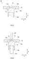
- a horn 80 is brought into contact with a bottom surface 74a of the recessed portion 74 and an anvil 82 is brought into contact with the second member 76 so as to sandwich the first member 72 and the second member 76 in the height direction Z.
- the horn 80 is attached to a press machine (not illustrated) provided with a vibration generator.
- the vibration generator is an apparatus that applies a necessary vibration required by ultrasonic welding to the horn 80.
- a shape of a pressure-welding portion of the horn 80 is not particularly limited as long as the pressure-welding portion is small enough to fit into the recessed portion 74.
- the anvil 82 is arranged inside a hollow structure of a swaging portion 76a of the second member 76 as shown in FIG. 6 . Accordingly, positioning of the anvil 82 can be readily performed.
- pressure is applied to the first member 72 and the second member 76 using the press machine.
- an ultrasonic vibration is applied to the horn 80 in a state where the pressure is being applied. While conditions of the pressure applied by the press machine and the ultrasonic vibration applied to the horn may be appropriately set in accordance with metallic species that constitute the first member 72 and the second member 76, dimensions of the first member 72 and the second member 76, a shape of the horn 80, and the like, for example, the pressure is applied within a range of 80 to 1600 N, the ultrasonic vibration is set to an amplitude of 20 to 80 ⁇ m and a frequency of 15 to 150 kHz, and energy of the horn 80 with respect to the pressure-welding portion is set to 30 to 500 J. Accordingly, ultrasonic welding in the recessed portion 74 can be realized and the terminal 70 with a structure disclosed herein can be fabricated.
- burrs 75 and metal surface irregularities may be created by the ultrasonic welding
- welding residue typically, the burrs 75
- irregularities that may be created on a surface to which the horn 80 is pressure-welded
- the terminal 70 manufactured according to this manufacturing method enables an external member such as a busbar to be welded to the plate surface (the other plate surface 72b) on an opposite side to the surface of the first member 72 to which the second member 76 is welded without performing surface treatment after the ultrasonic welding.
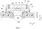
- the burrs 75 may be formed in the recessed portion 74 as described above, by sealing the recessed portion 74 with the external member, a secondary battery 1 and an assembled battery 10 provided with the terminal 70 can be manufactured without having to perform a step of cleaning the burrs 75. As shown in FIG.
- the terminal 70 can be installed in the secondary battery 1 (the lid 34) by inserting the second member 76 that constitutes the terminal 70 into the cylindrical portion 60a of the gasket 60, the terminal insertion hole 34a of the lid 34, the through-hole of the insulator 62, and the through-hole at the upper end of the internal terminal (in this case, the negative electrode internal terminal 52) in this order and causing the swaging portion 76a to protrude from the upper end of the internal terminal, and subsequently swaging the swaging portion 76a so that a compressive force is applied in the height direction Z in order to pressure-bond and fix the gasket 60, the lid 34, the insulator 62, and the negative electrode internal terminal 52 to each other.
- the busbar 14 (the external member) is arranged so as to seal the recessed portion 74 and the busbar 14 and the first member 72 are welded to each other.
- Providing a busbar welding portion 14a in a periphery of the recessed portion 74 enables the burrs 75 to be sealed in the recessed portion 74. Accordingly, the external member (for example, busbar) and the terminal 70 can be welded to each other without performing surface treatment after ultrasonic welding.
Landscapes
- Chemical & Material Sciences (AREA)
- Chemical Kinetics & Catalysis (AREA)
- Electrochemistry (AREA)
- General Chemical & Material Sciences (AREA)
- Engineering & Computer Science (AREA)
- Manufacturing & Machinery (AREA)
- Mechanical Engineering (AREA)
- Inorganic Chemistry (AREA)
- Connection Of Batteries Or Terminals (AREA)
- Electric Double-Layer Capacitors Or The Like (AREA)
- Battery Mounting, Suspending (AREA)
Applications Claiming Priority (1)
| Application Number | Priority Date | Filing Date | Title |
|---|---|---|---|
| JP2020155913A JP7252926B2 (ja) | 2020-09-17 | 2020-09-17 | 二次電池用端子および該端子を備えた二次電池 |
Publications (2)
| Publication Number | Publication Date |
|---|---|
| EP3972043A1 EP3972043A1 (en) | 2022-03-23 |
| EP3972043B1 true EP3972043B1 (en) | 2024-03-06 |
Family
ID=77519061
Family Applications (1)
| Application Number | Title | Priority Date | Filing Date |
|---|---|---|---|
| EP21193349.4A Active EP3972043B1 (en) | 2020-09-17 | 2021-08-26 | Terminal for secondary battery and secondary battery provided with the terminal |
Country Status (5)
| Country | Link |
|---|---|
| US (1) | US12100865B2 (enExample) |
| EP (1) | EP3972043B1 (enExample) |
| JP (4) | JP7252926B2 (enExample) |
| KR (1) | KR102641236B1 (enExample) |
| CN (1) | CN114204231B (enExample) |
Families Citing this family (8)
| Publication number | Priority date | Publication date | Assignee | Title |
|---|---|---|---|---|
| JP7252926B2 (ja) * | 2020-09-17 | 2023-04-05 | プライムプラネットエナジー&ソリューションズ株式会社 | 二次電池用端子および該端子を備えた二次電池 |
| JP7328270B2 (ja) * | 2021-03-11 | 2023-08-16 | プライムプラネットエナジー&ソリューションズ株式会社 | 端子部品および蓄電デバイス |
| JP7426356B2 (ja) | 2021-08-06 | 2024-02-01 | プライムプラネットエナジー&ソリューションズ株式会社 | 端子部品ならびに該端子部品を備える二次電池および組電池 |
| KR20240139202A (ko) | 2023-03-14 | 2024-09-23 | 주식회사 엘지에너지솔루션 | 이차전지용 단자 구조 및 이를 구비한 이차전지 |
| JP2025009344A (ja) | 2023-07-07 | 2025-01-20 | プライムプラネットエナジー&ソリューションズ株式会社 | 蓄電装置、蓄電装置用端子および蓄電装置の製造方法 |
| JP2025009346A (ja) | 2023-07-07 | 2025-01-20 | プライムプラネットエナジー&ソリューションズ株式会社 | 蓄電装置用端子および蓄電装置 |
| JP7738605B2 (ja) | 2023-07-07 | 2025-09-12 | プライムプラネットエナジー&ソリューションズ株式会社 | 蓄電装置用端子および蓄電装置 |
| KR20250073582A (ko) * | 2023-11-19 | 2025-05-27 | 삼성에스디아이 주식회사 | 배터리 셀 및 이를 구비하는 배터리 모듈 |
Family Cites Families (92)
| Publication number | Priority date | Publication date | Assignee | Title |
|---|---|---|---|---|
| JPH07224944A (ja) | 1994-02-15 | 1995-08-22 | Toyota Motor Corp | 異種金属部材における接合面のシール構造 |
| JPH09219204A (ja) | 1996-02-14 | 1997-08-19 | Fuji Elelctrochem Co Ltd | リチウム偏平形電池の製造方法 |
| JP3732945B2 (ja) | 1998-03-31 | 2006-01-11 | 三洋電機株式会社 | 密閉型電池 |
| JP2000164195A (ja) | 1998-11-24 | 2000-06-16 | Japan Storage Battery Co Ltd | 非水電解質二次電池 |
| US6440604B1 (en) | 1998-09-08 | 2002-08-27 | Japan Storage Battery Co., Ltd. | Cell |
| JP4099610B2 (ja) | 1998-09-08 | 2008-06-11 | 株式会社ジーエス・ユアサコーポレーション | 電池 |
| JP2001126706A (ja) | 1999-10-29 | 2001-05-11 | Yuasa Corp | 集合電池 |
| US6844110B2 (en) | 2000-05-24 | 2005-01-18 | Ngk Insulators, Ltd. | Lithium secondary cell and assembly thereof |
| JP2001357834A (ja) | 2000-06-16 | 2001-12-26 | Japan Storage Battery Co Ltd | 電 池 |
| JP3572404B2 (ja) * | 2002-03-04 | 2004-10-06 | 日産自動車株式会社 | 組電池 |
| JP4181880B2 (ja) | 2003-01-16 | 2008-11-19 | Fdkエナジー株式会社 | アルカリ乾電池 |
| JP3931983B2 (ja) * | 2003-06-26 | 2007-06-20 | 日本電気株式会社 | 電気リード部の構造、該リード部構造を有する電気デバイス、電池および組電池 |
| JP5118287B2 (ja) | 2004-03-29 | 2013-01-16 | 株式会社Gsユアサ | 電池 |
| JP5111991B2 (ja) | 2007-09-28 | 2013-01-09 | 株式会社東芝 | 電池 |
| JP2009110808A (ja) * | 2007-10-30 | 2009-05-21 | Sanyo Electric Co Ltd | 密閉型電池 |
| JP5595830B2 (ja) | 2009-08-26 | 2014-09-24 | 株式会社東芝 | 電池、組電池及び組電池の製造方法 |
| US8263255B2 (en) | 2009-10-01 | 2012-09-11 | Sb Limotive Co., Ltd. | Rechargeable battery and battery module |
| KR101084220B1 (ko) | 2009-10-30 | 2011-11-17 | 에스비리모티브 주식회사 | 이차전지의 단자유닛 및 그 제조방법 |
| JP5481178B2 (ja) | 2009-12-08 | 2014-04-23 | 日立ビークルエナジー株式会社 | 組電池および単電池 |
| KR101097227B1 (ko) | 2010-02-08 | 2011-12-21 | 에스비리모티브 주식회사 | 배터리모듈 및 그 제조방법 |
| US8956753B2 (en) | 2010-03-30 | 2015-02-17 | Samsung Sdi Co., Ltd. | Secondary battery and secondary battery module |
| JP6024095B2 (ja) | 2010-12-10 | 2016-11-09 | 株式会社Gsユアサ | 蓄電素子、蓄電素子の製造方法、及び、端子の製造方法 |
| US9023497B2 (en) | 2011-02-18 | 2015-05-05 | Samsung Sdi Co., Ltd. | Secondary battery |
| JP2012174452A (ja) | 2011-02-21 | 2012-09-10 | Sharp Corp | 二次電池 |
| WO2012118014A1 (ja) | 2011-02-28 | 2012-09-07 | 三洋電機株式会社 | バッテリシステム及びバッテリシステムを備える車両 |
| JP5578118B2 (ja) | 2011-03-10 | 2014-08-27 | 株式会社Gsユアサ | 電池および電池の製造方法 |
| WO2013013083A2 (en) | 2011-07-19 | 2013-01-24 | Velocys, Inc. | Microchannel reactors and fabrication processes |
| JP5639558B2 (ja) | 2011-09-29 | 2014-12-10 | 株式会社テクノアソシエ | 金属板と金属軸の結合構造及び密閉型電池の電極構造 |
| JP5941654B2 (ja) | 2011-10-27 | 2016-06-29 | 日立オートモティブシステムズ株式会社 | 単電池および組電池 |
| JP5611251B2 (ja) * | 2012-01-27 | 2014-10-22 | トヨタ自動車株式会社 | 密閉型二次電池 |
| JP5976340B2 (ja) | 2012-02-29 | 2016-08-23 | 三洋電機株式会社 | 角形二次電池の製造方法 |
| JP6112113B2 (ja) * | 2012-08-03 | 2017-04-12 | 株式会社村田製作所 | 電子デバイスの製造方法 |
| US9505082B2 (en) | 2012-08-28 | 2016-11-29 | Gs Yuasa International, Ltd. | Manufacturing method of electric storage apparatus and electric storage apparatus |
| US10003067B2 (en) | 2012-09-12 | 2018-06-19 | Gs Yuasa International Ltd. | Electric storage device and method for producing electric storage device |
| US11552377B2 (en) | 2012-11-26 | 2023-01-10 | Vehicle Energy Japan Inc. | Rectangular secondary battery |
| JP6249963B2 (ja) | 2012-12-25 | 2017-12-20 | 株式会社Gsユアサ | 蓄電素子の製造方法及び蓄電素子アセンブリの製造方法 |
| JP5682617B2 (ja) | 2012-12-25 | 2015-03-11 | トヨタ自動車株式会社 | 密閉型電池 |
| JP6077317B2 (ja) | 2013-01-29 | 2017-02-08 | 株式会社協豊製作所 | 蓄電池用端子 |
| CN105144432A (zh) | 2013-03-26 | 2015-12-09 | 株式会社杰士汤浅国际 | 蓄电元件、以及具备所述蓄电元件的蓄电装置 |
| JP2015011785A (ja) | 2013-06-26 | 2015-01-19 | 株式会社Gsユアサ | 蓄電装置及び該蓄電装置の製造方法 |
| JP6171692B2 (ja) | 2013-08-01 | 2017-08-02 | 新日鐵住金株式会社 | 摩擦攪拌点接合方法 |
| JP6070490B2 (ja) | 2013-09-11 | 2017-02-01 | 日立金属株式会社 | 電池用端子および電池用端子の製造方法 |
| JP6263358B2 (ja) | 2013-09-18 | 2018-01-17 | 株式会社ニューフレアテクノロジー | 検査方法および検査装置 |
| JP6327818B2 (ja) | 2013-09-19 | 2018-05-23 | 株式会社貴匠技研 | コネクタ端子構造の第1端子部材 |
| JP6269383B2 (ja) | 2013-09-24 | 2018-01-31 | 株式会社Gsユアサ | 蓄電装置 |
| JP5943396B2 (ja) | 2013-09-25 | 2016-07-05 | 株式会社日立金属ネオマテリアル | 電池用端子、電池用端子の製造方法および電池 |
| WO2015060175A1 (ja) * | 2013-10-23 | 2015-04-30 | 株式会社豊田自動織機 | 電流遮断装置を備えた蓄電装置 |
| CN105830253B (zh) | 2013-10-25 | 2019-04-02 | 日立汽车系统株式会社 | 方形二次电池 |
| JP2015099759A (ja) | 2013-11-20 | 2015-05-28 | 株式会社東芝 | 組電池用バスバーおよび組電池 |
| JP6146617B2 (ja) | 2014-02-12 | 2017-06-14 | トヨタ自動車株式会社 | 二次電池の製造方法 |
| KR102154332B1 (ko) | 2014-02-27 | 2020-09-09 | 삼성에스디아이 주식회사 | 이차 전지 |
| JP6363893B2 (ja) | 2014-07-08 | 2018-07-25 | 日立オートモティブシステムズ株式会社 | 二次電池 |
| US20170229700A1 (en) * | 2014-08-06 | 2017-08-10 | Hitachi Automotive Systems, Ltd. | Prismatic secondary battery |
| JP6404045B2 (ja) * | 2014-09-09 | 2018-10-10 | 三井化学株式会社 | 蓋体、電気素子、電気素子ユニット及び蓋体の製造方法 |
| JP6398602B2 (ja) | 2014-10-22 | 2018-10-03 | 株式会社Gsユアサ | 蓄電素子とその製造方法、および蓄電装置 |
| CN105552295B (zh) | 2014-10-24 | 2019-01-22 | 日立金属株式会社 | 电池用端子、电池用端子的制造方法和电池 |
| JP6581440B2 (ja) | 2014-10-24 | 2019-09-25 | 日立金属株式会社 | 電池用端子、電池用端子の製造方法および電池 |
| JP6467211B2 (ja) | 2014-12-12 | 2019-02-06 | 日立オートモティブシステムズ株式会社 | 蓄電モジュール |
| JP6631866B2 (ja) | 2015-01-09 | 2020-01-15 | 株式会社Gsユアサ | 蓄電装置 |
| JP5816763B1 (ja) | 2015-01-19 | 2015-11-18 | ヤマセ電気株式会社 | 異種材料と金属材料との界面が気密性を有する異種材料接合金属材料、異種材料同士との界面が気密性を有する異種材料接合材料 |
| KR101856820B1 (ko) | 2015-03-06 | 2018-05-10 | 주식회사 엘지화학 | 케이블형 이차전지 |
| JP6610989B2 (ja) | 2015-03-31 | 2019-11-27 | 株式会社Gsユアサ | 蓄電素子、及び蓄電素子の製造方法 |
| JP6427462B2 (ja) | 2015-04-23 | 2018-11-21 | 日立オートモティブシステムズ株式会社 | 角形二次電池 |
| JP6569322B2 (ja) | 2015-06-22 | 2019-09-04 | 三洋電機株式会社 | 二次電池及びそれを用いた組電池 |
| JP6403644B2 (ja) | 2015-07-23 | 2018-10-10 | 日立オートモティブシステムズ株式会社 | 二次電池 |
| CN107848064A (zh) | 2015-07-23 | 2018-03-27 | 日本轻金属株式会社 | 接合方法及散热器的制造方法 |
| JP6087413B1 (ja) * | 2015-11-05 | 2017-03-01 | 株式会社神戸製鋼所 | レーザー溶接性に優れた自動車バスバー用アルミニウム合金板 |
| JPWO2017141694A1 (ja) | 2016-02-19 | 2018-12-13 | 株式会社Gsユアサ | 蓄電素子及び蓄電素子の製造方法 |
| JP6731289B2 (ja) | 2016-06-22 | 2020-07-29 | プライムアースEvエナジー株式会社 | 電池の製造方法及び電池 |
| WO2018026726A1 (en) | 2016-08-01 | 2018-02-08 | Johnson Controls Technology Company | Weldable aluminum terminal pads of an electrochemical cell |
| US10369657B2 (en) | 2016-09-26 | 2019-08-06 | Ultex Corporation | Joining resonator or joining support jig |
| JP2018088464A (ja) | 2016-11-28 | 2018-06-07 | トヨタ自動車株式会社 | 半導体装置 |
| JP6814389B2 (ja) | 2017-04-10 | 2021-01-20 | トヨタ自動車株式会社 | 組電池 |
| JP2019009045A (ja) | 2017-06-27 | 2019-01-17 | 株式会社Gsユアサ | 蓄電素子 |
| JP6827386B2 (ja) | 2017-08-15 | 2021-02-10 | イーグル工業株式会社 | 超音波接合治具、超音波接合方法および接合構造 |
| JP6931460B2 (ja) | 2017-10-06 | 2021-09-08 | トヨタ自動車株式会社 | 電池および電池の製造方法 |
| JP2019075214A (ja) | 2017-10-12 | 2019-05-16 | 株式会社Gsユアサ | 蓄電素子、及び蓄電素子の製造方法 |
| JP6996308B2 (ja) | 2018-01-17 | 2022-01-17 | 三洋電機株式会社 | 二次電池及びその製造方法 |
| JP7001957B2 (ja) | 2018-03-02 | 2022-01-20 | トヨタ自動車株式会社 | 電池の製造方法および電池 |
| KR102557413B1 (ko) * | 2018-04-25 | 2023-07-18 | 주식회사 엘지에너지솔루션 | 리튬 금속 전극의 제조 방법 |
| JP7368080B2 (ja) | 2018-08-31 | 2023-10-24 | 三洋電機株式会社 | 二次電池 |
| KR102632924B1 (ko) | 2018-09-19 | 2024-02-02 | 삼성에스디아이 주식회사 | 이차 전지 |
| JP7085976B2 (ja) | 2018-12-20 | 2022-06-17 | 三洋電機株式会社 | 二次電池の製造方法 |
| JP2020107473A (ja) | 2018-12-27 | 2020-07-09 | 株式会社Gsユアサ | 蓄電素子 |
| JP7229027B2 (ja) * | 2019-01-29 | 2023-02-27 | 三洋電機株式会社 | 二次電池及びその製造方法 |
| CN209880722U (zh) | 2019-06-28 | 2019-12-31 | 宁德时代新能源科技股份有限公司 | 二次电池 |
| JP7304329B2 (ja) | 2020-09-17 | 2023-07-06 | プライムプラネットエナジー&ソリューションズ株式会社 | 二次電池ならびに二次電池用端子およびその製造方法 |
| JP7256780B2 (ja) | 2020-09-17 | 2023-04-12 | プライムプラネットエナジー&ソリューションズ株式会社 | 二次電池用端子および二次電池用端子の製造方法 |
| JP7245208B2 (ja) | 2020-09-17 | 2023-03-23 | プライムプラネットエナジー&ソリューションズ株式会社 | 二次電池用端子および該端子を備えた二次電池 |
| JP7252926B2 (ja) | 2020-09-17 | 2023-04-05 | プライムプラネットエナジー&ソリューションズ株式会社 | 二次電池用端子および該端子を備えた二次電池 |
| JP7402202B2 (ja) | 2021-07-15 | 2023-12-20 | プライムプラネットエナジー&ソリューションズ株式会社 | 端子部品および端子部品の製造方法 |
| JP7426356B2 (ja) | 2021-08-06 | 2024-02-01 | プライムプラネットエナジー&ソリューションズ株式会社 | 端子部品ならびに該端子部品を備える二次電池および組電池 |
-
2020
- 2020-09-17 JP JP2020155913A patent/JP7252926B2/ja active Active
-
2021
- 2021-08-17 US US17/404,616 patent/US12100865B2/en active Active
- 2021-08-26 EP EP21193349.4A patent/EP3972043B1/en active Active
- 2021-09-14 KR KR1020210122248A patent/KR102641236B1/ko active Active
- 2021-09-16 CN CN202111086085.6A patent/CN114204231B/zh active Active
-
2023
- 2023-03-23 JP JP2023046444A patent/JP7562740B2/ja active Active
- 2023-03-23 JP JP2023046442A patent/JP7696387B2/ja active Active
- 2023-03-23 JP JP2023046443A patent/JP7628148B2/ja active Active
Also Published As
| Publication number | Publication date |
|---|---|
| JP7628148B2 (ja) | 2025-02-07 |
| KR20220037366A (ko) | 2022-03-24 |
| US12100865B2 (en) | 2024-09-24 |
| US20220085469A1 (en) | 2022-03-17 |
| CN114204231B (zh) | 2024-12-24 |
| JP7252926B2 (ja) | 2023-04-05 |
| JP2023082048A (ja) | 2023-06-13 |
| JP2023076533A (ja) | 2023-06-01 |
| JP7696387B2 (ja) | 2025-06-20 |
| JP7562740B2 (ja) | 2024-10-07 |
| JP2022049726A (ja) | 2022-03-30 |
| KR102641236B1 (ko) | 2024-02-29 |
| JP2023093456A (ja) | 2023-07-04 |
| CN114204231A (zh) | 2022-03-18 |
| EP3972043A1 (en) | 2022-03-23 |
Similar Documents
| Publication | Publication Date | Title |
|---|---|---|
| EP3972043B1 (en) | Terminal for secondary battery and secondary battery provided with the terminal | |
| US11710880B2 (en) | Terminal for secondary battery and secondary battery provided with the terminal | |
| EP3972042B1 (en) | Terminal for secondary battery and method for manufacturing terminal for secondary battery | |
| CN115621675B (zh) | 端子部件以及端子部件的制造方法 | |
| JP2022139371A (ja) | 端子部品および蓄電デバイス | |
| US12444798B2 (en) | Power storage device | |
| US12278398B2 (en) | Sealed battery and method of manufacturing sealed battery | |
| JP7296996B2 (ja) | 電極端子およびその利用 | |
| CN115832543A (zh) | 二次电池 | |
| US20250015458A1 (en) | Electricity storage device, terminal for electricity storage device, and method for manufacturing electricity storage device | |
| JP2019129035A (ja) | 蓄電モジュール、及び、蓄電モジュールの製造方法 | |
| JP2022115148A (ja) | 二次電池および組電池 | |
| JP2021132017A (ja) | 蓄電装置 |
Legal Events
| Date | Code | Title | Description |
|---|---|---|---|
| PUAI | Public reference made under article 153(3) epc to a published international application that has entered the european phase |
Free format text: ORIGINAL CODE: 0009012 |
|
| STAA | Information on the status of an ep patent application or granted ep patent |
Free format text: STATUS: REQUEST FOR EXAMINATION WAS MADE |
|
| 17P | Request for examination filed |
Effective date: 20210826 |
|
| AK | Designated contracting states |
Kind code of ref document: A1 Designated state(s): AL AT BE BG CH CY CZ DE DK EE ES FI FR GB GR HR HU IE IS IT LI LT LU LV MC MK MT NL NO PL PT RO RS SE SI SK SM TR |
|
| RAP3 | Party data changed (applicant data changed or rights of an application transferred) |
Owner name: PRIME PLANET ENERGY & SOLUTIONS, INC. |
|
| STAA | Information on the status of an ep patent application or granted ep patent |
Free format text: STATUS: EXAMINATION IS IN PROGRESS |
|
| 17Q | First examination report despatched |
Effective date: 20230323 |
|
| GRAP | Despatch of communication of intention to grant a patent |
Free format text: ORIGINAL CODE: EPIDOSNIGR1 |
|
| STAA | Information on the status of an ep patent application or granted ep patent |
Free format text: STATUS: GRANT OF PATENT IS INTENDED |
|
| INTG | Intention to grant announced |
Effective date: 20231027 |
|
| P01 | Opt-out of the competence of the unified patent court (upc) registered |
Effective date: 20231030 |
|
| GRAS | Grant fee paid |
Free format text: ORIGINAL CODE: EPIDOSNIGR3 |
|
| GRAA | (expected) grant |
Free format text: ORIGINAL CODE: 0009210 |
|
| STAA | Information on the status of an ep patent application or granted ep patent |
Free format text: STATUS: THE PATENT HAS BEEN GRANTED |
|
| AK | Designated contracting states |
Kind code of ref document: B1 Designated state(s): AL AT BE BG CH CY CZ DE DK EE ES FI FR GB GR HR HU IE IS IT LI LT LU LV MC MK MT NL NO PL PT RO RS SE SI SK SM TR |
|
| REG | Reference to a national code |
Ref country code: CH Ref legal event code: EP |
|
| REG | Reference to a national code |
Ref country code: DE Ref legal event code: R096 Ref document number: 602021010042 Country of ref document: DE |
|
| REG | Reference to a national code |
Ref country code: IE Ref legal event code: FG4D |
|
| REG | Reference to a national code |
Ref country code: LT Ref legal event code: MG9D |
|
| PG25 | Lapsed in a contracting state [announced via postgrant information from national office to epo] |
Ref country code: LT Free format text: LAPSE BECAUSE OF FAILURE TO SUBMIT A TRANSLATION OF THE DESCRIPTION OR TO PAY THE FEE WITHIN THE PRESCRIBED TIME-LIMIT Effective date: 20240306 |
|
| REG | Reference to a national code |
Ref country code: NL Ref legal event code: MP Effective date: 20240306 |
|
| PG25 | Lapsed in a contracting state [announced via postgrant information from national office to epo] |
Ref country code: GR Free format text: LAPSE BECAUSE OF FAILURE TO SUBMIT A TRANSLATION OF THE DESCRIPTION OR TO PAY THE FEE WITHIN THE PRESCRIBED TIME-LIMIT Effective date: 20240607 |
|
| PG25 | Lapsed in a contracting state [announced via postgrant information from national office to epo] |
Ref country code: HR Free format text: LAPSE BECAUSE OF FAILURE TO SUBMIT A TRANSLATION OF THE DESCRIPTION OR TO PAY THE FEE WITHIN THE PRESCRIBED TIME-LIMIT Effective date: 20240306 Ref country code: RS Free format text: LAPSE BECAUSE OF FAILURE TO SUBMIT A TRANSLATION OF THE DESCRIPTION OR TO PAY THE FEE WITHIN THE PRESCRIBED TIME-LIMIT Effective date: 20240606 |
|
| PG25 | Lapsed in a contracting state [announced via postgrant information from national office to epo] |
Ref country code: ES Free format text: LAPSE BECAUSE OF FAILURE TO SUBMIT A TRANSLATION OF THE DESCRIPTION OR TO PAY THE FEE WITHIN THE PRESCRIBED TIME-LIMIT Effective date: 20240306 |
|
| PG25 | Lapsed in a contracting state [announced via postgrant information from national office to epo] |
Ref country code: RS Free format text: LAPSE BECAUSE OF FAILURE TO SUBMIT A TRANSLATION OF THE DESCRIPTION OR TO PAY THE FEE WITHIN THE PRESCRIBED TIME-LIMIT Effective date: 20240606 Ref country code: NO Free format text: LAPSE BECAUSE OF FAILURE TO SUBMIT A TRANSLATION OF THE DESCRIPTION OR TO PAY THE FEE WITHIN THE PRESCRIBED TIME-LIMIT Effective date: 20240606 Ref country code: LT Free format text: LAPSE BECAUSE OF FAILURE TO SUBMIT A TRANSLATION OF THE DESCRIPTION OR TO PAY THE FEE WITHIN THE PRESCRIBED TIME-LIMIT Effective date: 20240306 Ref country code: HR Free format text: LAPSE BECAUSE OF FAILURE TO SUBMIT A TRANSLATION OF THE DESCRIPTION OR TO PAY THE FEE WITHIN THE PRESCRIBED TIME-LIMIT Effective date: 20240306 Ref country code: GR Free format text: LAPSE BECAUSE OF FAILURE TO SUBMIT A TRANSLATION OF THE DESCRIPTION OR TO PAY THE FEE WITHIN THE PRESCRIBED TIME-LIMIT Effective date: 20240607 Ref country code: FI Free format text: LAPSE BECAUSE OF FAILURE TO SUBMIT A TRANSLATION OF THE DESCRIPTION OR TO PAY THE FEE WITHIN THE PRESCRIBED TIME-LIMIT Effective date: 20240306 Ref country code: ES Free format text: LAPSE BECAUSE OF FAILURE TO SUBMIT A TRANSLATION OF THE DESCRIPTION OR TO PAY THE FEE WITHIN THE PRESCRIBED TIME-LIMIT Effective date: 20240306 Ref country code: BG Free format text: LAPSE BECAUSE OF FAILURE TO SUBMIT A TRANSLATION OF THE DESCRIPTION OR TO PAY THE FEE WITHIN THE PRESCRIBED TIME-LIMIT Effective date: 20240306 |
|
| REG | Reference to a national code |
Ref country code: AT Ref legal event code: MK05 Ref document number: 1664450 Country of ref document: AT Kind code of ref document: T Effective date: 20240306 |
|
| PG25 | Lapsed in a contracting state [announced via postgrant information from national office to epo] |
Ref country code: SE Free format text: LAPSE BECAUSE OF FAILURE TO SUBMIT A TRANSLATION OF THE DESCRIPTION OR TO PAY THE FEE WITHIN THE PRESCRIBED TIME-LIMIT Effective date: 20240306 Ref country code: LV Free format text: LAPSE BECAUSE OF FAILURE TO SUBMIT A TRANSLATION OF THE DESCRIPTION OR TO PAY THE FEE WITHIN THE PRESCRIBED TIME-LIMIT Effective date: 20240306 |
|
| PG25 | Lapsed in a contracting state [announced via postgrant information from national office to epo] |
Ref country code: NL Free format text: LAPSE BECAUSE OF FAILURE TO SUBMIT A TRANSLATION OF THE DESCRIPTION OR TO PAY THE FEE WITHIN THE PRESCRIBED TIME-LIMIT Effective date: 20240306 |
|
| PG25 | Lapsed in a contracting state [announced via postgrant information from national office to epo] |
Ref country code: NL Free format text: LAPSE BECAUSE OF FAILURE TO SUBMIT A TRANSLATION OF THE DESCRIPTION OR TO PAY THE FEE WITHIN THE PRESCRIBED TIME-LIMIT Effective date: 20240306 |
|
| PG25 | Lapsed in a contracting state [announced via postgrant information from national office to epo] |
Ref country code: IS Free format text: LAPSE BECAUSE OF FAILURE TO SUBMIT A TRANSLATION OF THE DESCRIPTION OR TO PAY THE FEE WITHIN THE PRESCRIBED TIME-LIMIT Effective date: 20240706 |
|
| PG25 | Lapsed in a contracting state [announced via postgrant information from national office to epo] |
Ref country code: SM Free format text: LAPSE BECAUSE OF FAILURE TO SUBMIT A TRANSLATION OF THE DESCRIPTION OR TO PAY THE FEE WITHIN THE PRESCRIBED TIME-LIMIT Effective date: 20240306 Ref country code: PT Free format text: LAPSE BECAUSE OF FAILURE TO SUBMIT A TRANSLATION OF THE DESCRIPTION OR TO PAY THE FEE WITHIN THE PRESCRIBED TIME-LIMIT Effective date: 20240708 |
|
| PG25 | Lapsed in a contracting state [announced via postgrant information from national office to epo] |
Ref country code: CZ Free format text: LAPSE BECAUSE OF FAILURE TO SUBMIT A TRANSLATION OF THE DESCRIPTION OR TO PAY THE FEE WITHIN THE PRESCRIBED TIME-LIMIT Effective date: 20240306 Ref country code: EE Free format text: LAPSE BECAUSE OF FAILURE TO SUBMIT A TRANSLATION OF THE DESCRIPTION OR TO PAY THE FEE WITHIN THE PRESCRIBED TIME-LIMIT Effective date: 20240306 |
|
| PG25 | Lapsed in a contracting state [announced via postgrant information from national office to epo] |
Ref country code: AT Free format text: LAPSE BECAUSE OF FAILURE TO SUBMIT A TRANSLATION OF THE DESCRIPTION OR TO PAY THE FEE WITHIN THE PRESCRIBED TIME-LIMIT Effective date: 20240306 |
|
| PG25 | Lapsed in a contracting state [announced via postgrant information from national office to epo] |
Ref country code: PL Free format text: LAPSE BECAUSE OF FAILURE TO SUBMIT A TRANSLATION OF THE DESCRIPTION OR TO PAY THE FEE WITHIN THE PRESCRIBED TIME-LIMIT Effective date: 20240306 |
|
| PG25 | Lapsed in a contracting state [announced via postgrant information from national office to epo] |
Ref country code: SK Free format text: LAPSE BECAUSE OF FAILURE TO SUBMIT A TRANSLATION OF THE DESCRIPTION OR TO PAY THE FEE WITHIN THE PRESCRIBED TIME-LIMIT Effective date: 20240306 |
|
| PG25 | Lapsed in a contracting state [announced via postgrant information from national office to epo] |
Ref country code: SM Free format text: LAPSE BECAUSE OF FAILURE TO SUBMIT A TRANSLATION OF THE DESCRIPTION OR TO PAY THE FEE WITHIN THE PRESCRIBED TIME-LIMIT Effective date: 20240306 Ref country code: SK Free format text: LAPSE BECAUSE OF FAILURE TO SUBMIT A TRANSLATION OF THE DESCRIPTION OR TO PAY THE FEE WITHIN THE PRESCRIBED TIME-LIMIT Effective date: 20240306 Ref country code: RO Free format text: LAPSE BECAUSE OF FAILURE TO SUBMIT A TRANSLATION OF THE DESCRIPTION OR TO PAY THE FEE WITHIN THE PRESCRIBED TIME-LIMIT Effective date: 20240306 Ref country code: PT Free format text: LAPSE BECAUSE OF FAILURE TO SUBMIT A TRANSLATION OF THE DESCRIPTION OR TO PAY THE FEE WITHIN THE PRESCRIBED TIME-LIMIT Effective date: 20240708 Ref country code: PL Free format text: LAPSE BECAUSE OF FAILURE TO SUBMIT A TRANSLATION OF THE DESCRIPTION OR TO PAY THE FEE WITHIN THE PRESCRIBED TIME-LIMIT Effective date: 20240306 Ref country code: IS Free format text: LAPSE BECAUSE OF FAILURE TO SUBMIT A TRANSLATION OF THE DESCRIPTION OR TO PAY THE FEE WITHIN THE PRESCRIBED TIME-LIMIT Effective date: 20240706 Ref country code: EE Free format text: LAPSE BECAUSE OF FAILURE TO SUBMIT A TRANSLATION OF THE DESCRIPTION OR TO PAY THE FEE WITHIN THE PRESCRIBED TIME-LIMIT Effective date: 20240306 Ref country code: CZ Free format text: LAPSE BECAUSE OF FAILURE TO SUBMIT A TRANSLATION OF THE DESCRIPTION OR TO PAY THE FEE WITHIN THE PRESCRIBED TIME-LIMIT Effective date: 20240306 Ref country code: AT Free format text: LAPSE BECAUSE OF FAILURE TO SUBMIT A TRANSLATION OF THE DESCRIPTION OR TO PAY THE FEE WITHIN THE PRESCRIBED TIME-LIMIT Effective date: 20240306 |
|
| PG25 | Lapsed in a contracting state [announced via postgrant information from national office to epo] |
Ref country code: IT Free format text: LAPSE BECAUSE OF FAILURE TO SUBMIT A TRANSLATION OF THE DESCRIPTION OR TO PAY THE FEE WITHIN THE PRESCRIBED TIME-LIMIT Effective date: 20240306 |
|
| REG | Reference to a national code |
Ref country code: DE Ref legal event code: R097 Ref document number: 602021010042 Country of ref document: DE |
|
| PG25 | Lapsed in a contracting state [announced via postgrant information from national office to epo] |
Ref country code: IT Free format text: LAPSE BECAUSE OF FAILURE TO SUBMIT A TRANSLATION OF THE DESCRIPTION OR TO PAY THE FEE WITHIN THE PRESCRIBED TIME-LIMIT Effective date: 20240306 |
|
| PLBE | No opposition filed within time limit |
Free format text: ORIGINAL CODE: 0009261 |
|
| STAA | Information on the status of an ep patent application or granted ep patent |
Free format text: STATUS: NO OPPOSITION FILED WITHIN TIME LIMIT |
|
| PG25 | Lapsed in a contracting state [announced via postgrant information from national office to epo] |
Ref country code: DK Free format text: LAPSE BECAUSE OF FAILURE TO SUBMIT A TRANSLATION OF THE DESCRIPTION OR TO PAY THE FEE WITHIN THE PRESCRIBED TIME-LIMIT Effective date: 20240306 |
|
| PG25 | Lapsed in a contracting state [announced via postgrant information from national office to epo] |
Ref country code: DK Free format text: LAPSE BECAUSE OF FAILURE TO SUBMIT A TRANSLATION OF THE DESCRIPTION OR TO PAY THE FEE WITHIN THE PRESCRIBED TIME-LIMIT Effective date: 20240306 |
|
| 26N | No opposition filed |
Effective date: 20241209 |
|
| REG | Reference to a national code |
Ref country code: CH Ref legal event code: PL |
|
| PG25 | Lapsed in a contracting state [announced via postgrant information from national office to epo] |
Ref country code: LU Free format text: LAPSE BECAUSE OF NON-PAYMENT OF DUE FEES Effective date: 20240826 |
|
| PG25 | Lapsed in a contracting state [announced via postgrant information from national office to epo] |
Ref country code: SI Free format text: LAPSE BECAUSE OF FAILURE TO SUBMIT A TRANSLATION OF THE DESCRIPTION OR TO PAY THE FEE WITHIN THE PRESCRIBED TIME-LIMIT Effective date: 20240306 Ref country code: MC Free format text: LAPSE BECAUSE OF FAILURE TO SUBMIT A TRANSLATION OF THE DESCRIPTION OR TO PAY THE FEE WITHIN THE PRESCRIBED TIME-LIMIT Effective date: 20240306 Ref country code: CH Free format text: LAPSE BECAUSE OF NON-PAYMENT OF DUE FEES Effective date: 20240831 |
|
| REG | Reference to a national code |
Ref country code: BE Ref legal event code: MM Effective date: 20240831 |
|
| PG25 | Lapsed in a contracting state [announced via postgrant information from national office to epo] |
Ref country code: BE Free format text: LAPSE BECAUSE OF NON-PAYMENT OF DUE FEES Effective date: 20240831 |
|
| PG25 | Lapsed in a contracting state [announced via postgrant information from national office to epo] |
Ref country code: IE Free format text: LAPSE BECAUSE OF NON-PAYMENT OF DUE FEES Effective date: 20240826 |
|
| PGFP | Annual fee paid to national office [announced via postgrant information from national office to epo] |
Ref country code: DE Payment date: 20250717 Year of fee payment: 5 |
|
| PGFP | Annual fee paid to national office [announced via postgrant information from national office to epo] |
Ref country code: GB Payment date: 20250829 Year of fee payment: 5 |
|
| PGFP | Annual fee paid to national office [announced via postgrant information from national office to epo] |
Ref country code: FR Payment date: 20250717 Year of fee payment: 5 |