EP3955771B1 - Möbelelement - Google Patents
Möbelelement Download PDFInfo
- Publication number
- EP3955771B1 EP3955771B1 EP20720392.8A EP20720392A EP3955771B1 EP 3955771 B1 EP3955771 B1 EP 3955771B1 EP 20720392 A EP20720392 A EP 20720392A EP 3955771 B1 EP3955771 B1 EP 3955771B1
- Authority
- EP
- European Patent Office
- Prior art keywords
- furniture
- furniture element
- bearing
- bottom plate
- plate
- Prior art date
- Legal status (The legal status is an assumption and is not a legal conclusion. Google has not performed a legal analysis and makes no representation as to the accuracy of the status listed.)
- Active
Links
Images







Classifications
-
- A—HUMAN NECESSITIES
- A47—FURNITURE; DOMESTIC ARTICLES OR APPLIANCES; COFFEE MILLS; SPICE MILLS; SUCTION CLEANERS IN GENERAL
- A47B—TABLES; DESKS; OFFICE FURNITURE; CABINETS; DRAWERS; GENERAL DETAILS OF FURNITURE
- A47B17/00—Writing-tables
- A47B17/06—Writing-tables with parts, e.g. trays, movable on a pivot or by chains or belts
-
- A—HUMAN NECESSITIES
- A47—FURNITURE; DOMESTIC ARTICLES OR APPLIANCES; COFFEE MILLS; SPICE MILLS; SUCTION CLEANERS IN GENERAL
- A47B—TABLES; DESKS; OFFICE FURNITURE; CABINETS; DRAWERS; GENERAL DETAILS OF FURNITURE
- A47B49/00—Revolving cabinets or racks; Cabinets or racks with revolving parts
- A47B49/004—Cabinets with compartments provided with trays revolving on a vertical axis
- A47B49/006—Corner cabinets
-
- A—HUMAN NECESSITIES
- A47—FURNITURE; DOMESTIC ARTICLES OR APPLIANCES; COFFEE MILLS; SPICE MILLS; SUCTION CLEANERS IN GENERAL
- A47B—TABLES; DESKS; OFFICE FURNITURE; CABINETS; DRAWERS; GENERAL DETAILS OF FURNITURE
- A47B9/00—Tables with tops of variable height
-
- A—HUMAN NECESSITIES
- A47—FURNITURE; DOMESTIC ARTICLES OR APPLIANCES; COFFEE MILLS; SPICE MILLS; SUCTION CLEANERS IN GENERAL
- A47B—TABLES; DESKS; OFFICE FURNITURE; CABINETS; DRAWERS; GENERAL DETAILS OF FURNITURE
- A47B17/00—Writing-tables
- A47B17/06—Writing-tables with parts, e.g. trays, movable on a pivot or by chains or belts
- A47B17/065—Pivotally mounted auxiliary tables
-
- A—HUMAN NECESSITIES
- A47—FURNITURE; DOMESTIC ARTICLES OR APPLIANCES; COFFEE MILLS; SPICE MILLS; SUCTION CLEANERS IN GENERAL
- A47B—TABLES; DESKS; OFFICE FURNITURE; CABINETS; DRAWERS; GENERAL DETAILS OF FURNITURE
- A47B49/00—Revolving cabinets or racks; Cabinets or racks with revolving parts
-
- A—HUMAN NECESSITIES
- A47—FURNITURE; DOMESTIC ARTICLES OR APPLIANCES; COFFEE MILLS; SPICE MILLS; SUCTION CLEANERS IN GENERAL
- A47B—TABLES; DESKS; OFFICE FURNITURE; CABINETS; DRAWERS; GENERAL DETAILS OF FURNITURE
- A47B49/00—Revolving cabinets or racks; Cabinets or racks with revolving parts
- A47B49/004—Cabinets with compartments provided with trays revolving on a vertical axis
-
- A—HUMAN NECESSITIES
- A47—FURNITURE; DOMESTIC ARTICLES OR APPLIANCES; COFFEE MILLS; SPICE MILLS; SUCTION CLEANERS IN GENERAL
- A47B—TABLES; DESKS; OFFICE FURNITURE; CABINETS; DRAWERS; GENERAL DETAILS OF FURNITURE
- A47B53/00—Cabinets or racks having several sections one behind the other
-
- A—HUMAN NECESSITIES
- A47—FURNITURE; DOMESTIC ARTICLES OR APPLIANCES; COFFEE MILLS; SPICE MILLS; SUCTION CLEANERS IN GENERAL
- A47B—TABLES; DESKS; OFFICE FURNITURE; CABINETS; DRAWERS; GENERAL DETAILS OF FURNITURE
- A47B77/00—Kitchen cabinets
- A47B77/02—General layout, e.g. relative arrangement of compartments, working surface or surfaces, supports for apparatus
- A47B77/022—Work tops
-
- A—HUMAN NECESSITIES
- A47—FURNITURE; DOMESTIC ARTICLES OR APPLIANCES; COFFEE MILLS; SPICE MILLS; SUCTION CLEANERS IN GENERAL
- A47B—TABLES; DESKS; OFFICE FURNITURE; CABINETS; DRAWERS; GENERAL DETAILS OF FURNITURE
- A47B77/00—Kitchen cabinets
- A47B77/04—Provision for particular uses of compartments or other parts ; Compartments moving up and down, revolving parts
- A47B77/10—Provision for particular uses of compartments or other parts ; Compartments moving up and down, revolving parts with members movable outwards to a position of use, e.g. tables, ironing boards
-
- A—HUMAN NECESSITIES
- A47—FURNITURE; DOMESTIC ARTICLES OR APPLIANCES; COFFEE MILLS; SPICE MILLS; SUCTION CLEANERS IN GENERAL
- A47B—TABLES; DESKS; OFFICE FURNITURE; CABINETS; DRAWERS; GENERAL DETAILS OF FURNITURE
- A47B85/00—Furniture convertible into other kinds of furniture
-
- A—HUMAN NECESSITIES
- A47—FURNITURE; DOMESTIC ARTICLES OR APPLIANCES; COFFEE MILLS; SPICE MILLS; SUCTION CLEANERS IN GENERAL
- A47B—TABLES; DESKS; OFFICE FURNITURE; CABINETS; DRAWERS; GENERAL DETAILS OF FURNITURE
- A47B9/00—Tables with tops of variable height
- A47B9/04—Tables with tops of variable height with vertical spindle
-
- A—HUMAN NECESSITIES
- A47—FURNITURE; DOMESTIC ARTICLES OR APPLIANCES; COFFEE MILLS; SPICE MILLS; SUCTION CLEANERS IN GENERAL
- A47B—TABLES; DESKS; OFFICE FURNITURE; CABINETS; DRAWERS; GENERAL DETAILS OF FURNITURE
- A47B9/00—Tables with tops of variable height
- A47B9/20—Telescopic guides
-
- A—HUMAN NECESSITIES
- A47—FURNITURE; DOMESTIC ARTICLES OR APPLIANCES; COFFEE MILLS; SPICE MILLS; SUCTION CLEANERS IN GENERAL
- A47B—TABLES; DESKS; OFFICE FURNITURE; CABINETS; DRAWERS; GENERAL DETAILS OF FURNITURE
- A47B2220/00—General furniture construction, e.g. fittings
- A47B2220/0061—Accessories
-
- A—HUMAN NECESSITIES
- A47—FURNITURE; DOMESTIC ARTICLES OR APPLIANCES; COFFEE MILLS; SPICE MILLS; SUCTION CLEANERS IN GENERAL
- A47B—TABLES; DESKS; OFFICE FURNITURE; CABINETS; DRAWERS; GENERAL DETAILS OF FURNITURE
- A47B81/00—Cabinets or racks specially adapted for other particular purposes, e.g. for storing guns or skis
- A47B81/002—Corner cabinets; Cabinets designed for being placed in a corner or a niche
-
- A—HUMAN NECESSITIES
- A47—FURNITURE; DOMESTIC ARTICLES OR APPLIANCES; COFFEE MILLS; SPICE MILLS; SUCTION CLEANERS IN GENERAL
- A47B—TABLES; DESKS; OFFICE FURNITURE; CABINETS; DRAWERS; GENERAL DETAILS OF FURNITURE
- A47B96/00—Details of cabinets, racks or shelf units not covered by a single one of groups A47B43/00 - A47B95/00; General details of furniture
- A47B96/02—Shelves
- A47B96/025—Shelves with moving elements, e.g. movable extensions or link elements
Definitions
- the present invention relates to a furniture element, in particular a shelf or shelf, according to the preamble of claim 1.
- Furniture elements such as shelves or shelves, in which a support plate and a guided on this shelf is arranged at the same time rotationally and translationally movable shelf are, for example, from JP10318669 , the DE 10 2017 120 160 A1 or the DE 10 2017 106 170 A1 known.
- a shelving unit with two shelves that can be moved at an angle of 45° from a corner of a piece of furniture.
- a guide groove aligned at an angle of 45° to the side walls of the body, is provided in a base of the body for a rotary cylinder protruding downwards from the shelf, so that the respective shelf can be moved from its initial position in the corner of the furniture body first linearly along the guide groove into a rotary position displaceable and after reaching this rotational position, the shelf is freely rotatable.
- a body is a furniture component with a base and at least one closed side wall, behind which at least one storage element, for example a shelf, is arranged.
- the furniture element has a base plate arranged on a body of the furniture element.
- the body of the furniture element can be moved relative to the base plate from a starting position into an intermediate position and further into an open position and back.
- the body In the intermediate position, the body is rotated in a rotational direction relative to the base plate and is displaced in a predetermined direction. In the starting position and in the open position, the body is congruent with the base plate, i.e. it does not protrude beyond the dimensions of the base plate, but the body is rotated by 180° in each case.
- one of the preferably two running grooves of the base plate can be designed as a running groove open towards an edge of the base plate.
- the at least one running groove of the base plate is formed in each case mirror-symmetrically with respect to an axis of symmetry running at an oblique angle to a side edge of the base plate.
- At least one running groove of the bearing plate can in each case be formed mirror-symmetrically to an axis of symmetry running at an oblique angle to a side edge of the bearing plate.
- the body has a bearing plate on its side facing the base plate, at least one running groove being formed on the side of the bearing plate facing the base plate, and the at least one running groove of the bearing plate being mirror-symmetrical to an axis of symmetry running at an oblique angle to a side edge of the bearing plate.
- the rolling elements are arranged on at least two circles, the axes of symmetry of the arrangement of rolling elements on one circle being inclined by 45° to the axes of symmetry of the arrangement of rolling elements on the other circle.
- Such a furniture element can be set down, for example, in a corner of the room consisting of two side walls that are at an angle to one another and rotated out of this corner in a simple manner, so that the furniture element is parked in a starting position, for example, in such a way that the furniture element is covered by the side walls of the body and in an opening position rotated by 90° or 180°, for example, is rotated out of the corner in such a way that the at least one storage level of the furniture element is freely accessible to a user.
- Such a furniture element according to the invention standing on a room wall or in a room corner, can be moved from a closed position by side walls of the body of the furniture element into an open position with the same basic position by turning.
- Access to the contents of the furniture element is made possible in a simple manner by an at least partially combined translational-rotational movement of the furniture element.
- the proportions of translation and rotation in the overall movement can vary over the course of movement, depending on the design of the running grooves.
- a translation/rotation bearing formed from a base plate, bearing plate, rolling element and rolling element cage can be provided as a kit and can in particular also be subsequently integrated into the base of a furniture element.
- the axis of symmetry runs at an angle of 45° to a side edge of the base plate and/or the bearing plate.
- a base of the body has a recess on its side facing the base plate, in which a bearing plate is fastened, in whose side facing the base plate at least one running groove is formed.
- the bearing plate can also be formed integrally with the bottom of the body.
- the running grooves formed in the bearing surface of the body are designed as closed, circumferential running grooves and thus enable reliable guidance of the rolling elements.
- the furniture element can preferably have a body with at least one closed side wall.
- This body can be designed in such a way that, in a starting situation, the contents of the furniture element are concealed and kitchen utensils such as a coffee maker or kettle therefore simply "disappear" when not in use.
- the body of the furniture element has a number of storage levels, as a result of which the storage space of the furniture element is multiplied in a simple manner.
- the rolling elements are accommodated captively in at least one rolling element cage, which in particular facilitates the assembly of the rolling elements between the running grooves.
- a further translation/rotation bearing is fixed on a cover plate of the furniture body. This allows in particular the arrangement of such a furniture element in a piece of furniture such as a cooking island or, for example, in a corner of a kitchen furniture assembly that is open on two sides. This will create a Good running behavior of the furniture element is ensured and tilting is prevented.
- Such an arrangement has the advantage, in particular compared to a larder pull-out, that by guiding the furniture element over two such bearings, the furniture element can be approached simultaneously in both bearings, in particular at the bottom and at the top.
- the running grooves formed in the bearing plate form at least one outer running groove and one inner running groove.
- a third running groove is formed between the outer running groove and the inner running groove.
- Such a third running groove serves to carry out additional functions such as in particular limiting the rotation of the furniture element.
- such a third running groove must also be formed in the base plate.
- a fixing device is provided on the body of the furniture element for the vertical fixing of the base plate.
- the base plate has a slot into which a guide sleeve protrudes, which comes out of the base plate facing underside of the floor protrudes and thus performs the translational movement.
- this ensures a permanent connection between the storage plate and the base plate, and thus the functionality of the storage facility.
- a piece of furniture according to the invention has a body with several side walls and/or partitions and a cover plate. At least one furniture element, as described above, is arranged in the furniture according to the invention.
- the furniture element is particularly preferably arranged in a corner area of the furniture.
- Such furniture elements are particularly preferably arranged in at least two corner areas of the furniture.
- a further piece of furniture according to the invention has at least two furniture elements according to the invention, which are arranged in a tandem arrangement with translation/rotation bearings as described above, and a cover plate which covers the at least two furniture elements.
- This piece of furniture explicitly dispenses with the use of rigid side or partition walls to connect the floor to the top panel.
- the cover plate is thus supported exclusively by the at least two furniture parts according to the invention, and the stability of the furniture is ensured by the storage of the built-in at least two furniture elements. This enables in particular the arrangement of such a furniture element in a free-standing piece of furniture.
- Another piece of furniture according to the invention with a first body and a furniture element has, in a preferred variant, a body that can be placed in a fixed position on a floor with frictional engagement.
- Such a piece of furniture can be used, for example, as a table, in particular a desk or as a kitchen work table, in which the furniture element can be moved relative to the fixed furniture body using the translation/rotation bearing relative to the fixed furniture body from a position of the furniture element that covers the body to a position that does not completely cover the body Position of the furniture element and can be moved back.
- the furniture element in the open position, can be aligned perpendicular to the fixed furniture body.
- a first lifting device can additionally be attached to the body.
- the furniture element may have a second lifting device operable synchronously with the first lifting device, the translation-rotation bearing of the furniture element being mounted on the first lifting device.
- top, bottom, left, right, front, back, etc. refer exclusively to the exemplary representation and position of the furniture element, body, running grooves, base plate, rolling elements and the like selected in the respective figures. These terms are not to be understood as limiting, i.e. these references can change due to different working positions or the mirror-symmetrical design or the like.
- Furniture element 2 shown is designed as an example of a shelf with a square base and three storage compartments.
- the furniture element 2 has a body 22, with a floor 23 and several shelves 25.
- the uppermost of the shelves 25 here forms the ceiling of the shelf, so that it is closed at the top.
- the body 22 of the furniture element 2 also has two side walls 24 which enclose the furniture element 2 from two sides.
- the furniture element 2 also has a base plate 21 arranged on the body 22 , here on the bottom 23 of the furniture element 2 .
- mutually facing bearing surfaces of the body 22 and the base plate 21 have respective running grooves 27, 28 in which rolling elements 51 are guided, which serve to mount the body 22 in a movable manner relative to the base plate 21.
- the running grooves 27 assigned to the body 22 are arranged on a bearing plate 26 which is fixed to the bottom 23 of the body 22 .
- the bearing plate 26 can also be an integral part of the floor 23 .
- the rolling elements 51 are mounted in a rolling element cage 5, which in the embodiment variant shown here is designed as a square-shaped frame, with a total of eight rolling elements 51 mounted therein, preferably designed as balls.
- the rolling elements 51 are each arranged in the corners of the rolling element cage 5, which is designed as a square frame. Four more rolling elements are placed centrally on the respective sides of the rolling element cage 5 .
- the running grooves 27 on the underside of the bearing plate 26 facing the base plate 21 are designed as closed, circumferential running grooves
- the preferably two running grooves 28 of the base plate 21 are each formed mirror-symmetrical to a symmetry axis running at an oblique angle, preferably at 45°, to a side edge of the base plate 21 .
- the axis of symmetry runs parallel to the side edge of the base plate 21.
- One of these two running grooves 28 is designed as a closed, circumferential running groove.
- the second of these running grooves 28 is designed in such a way that the ends of this running groove open into two side edges of the base plate 21 which are at an angle to one another and are therefore designed as open running grooves.
- This configuration of the running grooves 28 and the base plate 21 enable the body 22 of the furniture element 2 to be unscrewed from a position in the Figures 1 to 3 schematically illustrated room corner 4, consisting of a floor 41 on which the floor panel 21 of the furniture element 2 rests and two side walls 42, 43, which are aligned here at right angles to one another, with two of the side edges of the floor panel 21 being positioned close to the side walls 42, 43, so that the furniture element 2 is positioned overall in the corner of the room.
- the rotation and translation of the body 22 relative to the base plate 21 made possible by the running grooves 28 in the base plate 21 and the running grooves 27 in the bearing plate 26 and the rolling elements 51 arranged between these enable the furniture element 2 to be positioned in an in 1 shown starting position in the corner of the room 4.
- the furniture element 2 is closed, ie covered by the side walls 24, which prevents access to items stored in the furniture element 2 or from dust or Splash water protects and gives an aesthetic impression of the furniture element 2.
- the furniture element 2 is opened, i.e. the side walls 24 of the body 22 are moved during the rotation into a position in which the side walls 24 are arranged directly opposite the side walls 42, 43. so that objects stored in the furniture element 2 are now freely accessible.
- the base plate 21 has a slot 29 which is aligned in the direction of the axis of symmetry of the running grooves 28 of the base plate 21.
- a guide sleeve 71 protrudes into this slot 29 and is fixed with a screw 72 protruding from the underside of the base 23 facing the base plate 21 .
- This screw 72 is positioned centrally in the base 23 of the body 22 of the furniture element 2 .
- the in 1 furniture element 2 positioned in the corner of the room 4 can also be moved out of the corner of the room 4 in direction A and essentially simultaneously by rotating about a variable vertical axis of rotation from the in 1 illustrated initial position in a direction of rotation M 1 , M 2 in the 3 shown open position are rotated.
- the proportions of translation and rotation in the overall movement can vary over the course of the movement.
- a third groove 28c formed in an alternative embodiment in the base plate 21 and in the bearing plate 26 in addition to an outer groove 28a and an inner groove 28b.
- Such a third running groove 28c enables additional functions during the translational-rotational movement of the furniture element 2, 3.
- a third running groove 28c following a section of the outer running groove 28a radially to the origin of the rotational movement and lying radially further inwards is used here to limit the rotation of the furniture element.
- rolling element cage 5' which is shaped here approximately square with slightly radially inwardly bent sides, with recesses for rolling elements 51, which are arranged in the outer corners of the rolling element cage 5', for rolling elements 51, which can be moved in the outer running groove 28a are.
- rolling elements 51 are arranged on an outer circle K 1 .
- receptacles for further rolling elements 51 are formed, which can be moved in the inner running groove 28b.
- These rolling bodies 51 are arranged on an inner circle K 2 .
- the rolling element 51 which is to be guided in the third running groove 28c, is provided radially inwardly of one of the rolling elements 51 arranged in the corners of the rolling element cage 5'.
- This rolling element 51 is arranged on a central circle K 3 .
- the symmetry axes SK 1 of the rolling element arrangement 51 on the circle K 1 are inclined by 45° to the symmetry axes SK 2 of the rolling element arrangement 51 on the circle K 2 .
- inner running grooves 27a and outer running grooves 27b are also formed in the bearing plate 26, as well as a further third running groove 27c, which is also formed radially further inwards to the origin of rotation U relative to a section of one of the outer running grooves 27b.
- the running grooves 27a and 27b are shaped in such a way that they are arranged symmetrically both to a vertical axis of symmetry S 1 and to a horizontal axis of symmetry S 2 .
- figure 6 shows further embodiment variants for rolling element cages 5, 5′′ with rolling element seats which are arranged in such a way that they are arranged correspondingly on an outer circle K 1 and on an inner circle K 2 .
- a translation/rotation bearing 6 is arranged both below a base 33 of the body 32 of the furniture element 3 and above a cover plate 31 of the furniture body 32 of the furniture element 3, with the upper bearing 6 being arranged with the base plate 61 at the top.
- Both the base 33 and the cover plate 31 form a cavity with an upper edge or lower edge of the furniture body 32, in which at least part of the bearing 6 is accommodated.
- a fixing device 7 with a screw 72 and a guide sleeve 71 and a rolling element cage 62 with rolling elements 66 are also present in this exemplary embodiment.
- the base plate 61 corresponds to the base plate 21
- the bearing plate 63 corresponds to the bearing plate 26.
- furniture element 3 is this preferably in a piece of furniture 8 as in the Figures 8 to 15 is shown, preferably used.
- Furniture 8 shown here is, for example, kitchen furniture in the form of a cooking island.
- other locations for such a furniture element 3 are also conceivable.
- feet 68 are attached to a bottom of the base plate facing away from the running grooves 64. These feet 68 can be designed to be adjustable.
- the bearing plate 63 is preferably attached to the underside of the base 33 of the body 32 of the furniture element 3 facing the base plate 61 . It would also be conceivable here to work the running grooves 65 directly into the underside of the floor 33 instead of the bearing plate 63 .
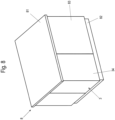
- figure 8 shows the piece of furniture 8 designed here as an island piece of furniture with a cover plate 81, several side walls 83 and a floor panel 82 with a furniture element 3 arranged in a corner in the closed state of the furniture element 3.
- the feet 68 are arranged behind the floor panel 82.
- figure 9 shows the furniture element 3 in a slightly open position
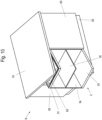
- figure 10 shows the furniture element 3 in an almost fully rotated open position
- figure 11 shows the piece of furniture 8 with the completely open furniture element 3.
- the piece of furniture 8 is also shown with dashed lines to show the furniture element 3 installed in the piece of furniture 8 below the cover plate 81.
- FIGs 13 to 15 show possible variants of such a piece of furniture with a furniture element 3 ( figure 13 ), two such furniture elements 3 ( figure 14 ) and four such furniture elements 3 ( figure 15 ).
- a furniture element 3 figure 13
- two such furniture elements 3 figure 14
- four such furniture elements 3 figure 15
- preferably only one common cover plate 81 is used.
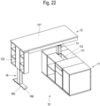
- FIGS. 16 to 22 12 show a further embodiment of a piece of furniture 10 according to the invention with a furniture element 12 which can be moved in translation and rotation relative to a furniture carcass 11 which is fixed or frictionally engaged on a floor of a room.
- the furniture 10 is, as in particular in the figures 16 and 20 to 22 is shown, designed as a desk furniture or kitchen island or kitchen work table or the like, with the firmly established on the room floor Furniture body 11 and the furniture element 12 that can be moved in translation and rotation relative to it.
- the furniture carcass 11 has a receptacle 112 in a central area of a work surface 111 which is used to accommodate a first lifting device 13 .
- the lifting device 13 embodied here as a telescopic lifting device is accommodated in the receptacle 112 of the furniture body 11 , telescopic elements 131 , 132 , 133 being able to be moved upwards out of the receptacle 112 .
- a support plate 134 is mounted on the uppermost of the telescopic elements 133 .
- a base plate 91 of a further variant embodiment of a translation/rotation bearing 9 is fastened to this support plate 134 .
- the furniture element 12 has, as exemplified in figure 17 is shown, a body 121 with a worktop, at the bottom of which the bearing plate 93 of the translation-rotation bearing 9 is attached.
- a side part 122 is arranged, in particular fastened, at one end of the body 121 and has a central receptacle for receiving a second lifting device 16 .
- the structure of the second lifting device 16 preferably corresponds to that of the first lifting device 13, ie it also has a first, a second and a third telescopic element 161, 162, 163.
- a foot 165 with at least two rolling elements 166 is arranged on the lowest, first telescopic element 161 of this lifting device 16 .
- the side part 122 thus serves as the second leg of the furniture element 12 for the lifting device 16 arranged on it.
- the furniture element 12 is thus supported on the one hand by the side part 122 and the second lifting device 16 arranged thereon and via the first lifting device 13 .
- the lifting device 13 supports the body 121 of the furniture element 12 via the translation/rotation bearing 9 accommodated between them.
- the furniture element 12 can thus be moved from an in figure 16 shown initial position, in which the furniture element 12 covers the furniture body 11, here completely, by synchronous actuation of the lifting devices 13, 16, with which the furniture element 12 can be raised relative to the furniture body 11, up to the in figure 20 shown open position are moved In the open position, the upper side of the body 121 of the furniture element 12 serving as a work surface is aligned perpendicularly to the work surface 111 of the furniture body 11 .
- Other opening positions are also conceivable.
- the furniture element 12 can be moved through a larger or smaller angle, for example 180°.
- the arrangement of the translational-rotational bearing 9 on the support plate 134 of the first lifting device 13 makes it possible, when the furniture body 11 is standing in a corner of the room, to lift the furniture element 12 out of the in figure 16 position shown in the in figure 20 To move the position shown without the furniture element 12 protruding beyond a rear edge of the furniture body 11 during the movement. This is very advantageous when the furniture body 11 is arranged against a wall or in a corner.
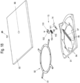
- Translation-rotation bearing 9 shown is in detail in the figures 18 and 19 shown.
- the base plate 91 also has running grooves 94 on its bearing surface facing the bearing plate 93 for guiding rolling elements 51 embodied here as balls.
- the rolling elements 51 are also accommodated in a rolling element cage 92 to prevent them from being lost.
- the rolling element cage 92 is here as in figure 7 shown embodiment is circular with a plurality of radially outwardly extending arms.
- a guide channel 97 is provided centrally and diagonally to two side edges of the base plate 91 aligned at right angles to one another.
- a guide carriage 151 is slidably mounted in this guide channel 97 .
- the guide carriage 151 as part of a fixing device 15 has on its upper side facing the bearing plate 93 or the body 121 of the furniture element 12 a bearing neck 152 which protrudes into an opening 99 in the bearing plate 93 and which is preferably formed on the upper side of the guide carriage 151.
- This bearing neck 152 serves as an axis for a roller bearing ring 157, in particular a ball bearing ring, which is inserted into the opening 99 of the bearing plate 93, which is preferably designed as a bore, and which enables a low-friction rotational movement of the bearing plate 93 relative to the guide carriage 151 and thus relative to the base plate 91.
- a roller bearing with at least two rollers 154 arranged one behind the other in the longitudinal direction of the guide channel 97 is arranged, in particular fastened, on the underside of the guide carriage 151 facing away from the bearing plate 93 .
- Each of these rollers 154 has a peripheral V-shaped groove 155 into which V-shaped webs 95 forming running surfaces for the rollers 154 protrude from opposite side walls of the guide channel 97 .
- a push to move mechanism shown in the form of an ejection element 14 that consists of an energy store 141 and a plunger 142 and is arranged in the guide channel 97 in order to eject the furniture element 12 after unlocking in a direction of movement.
- the piece of furniture can also be in the form of desk furniture or a kitchen island or kitchen work table or the like, without an additional second lifting device on the furniture element 12.
- the furniture part that can be moved in translation and rotation is carried only by the first lifting device arranged on the stationary furniture body.
Landscapes
- Rolling Contact Bearings (AREA)
- Combinations Of Kitchen Furniture (AREA)
- Tables And Desks Characterized By Structural Shape (AREA)
- Assembled Shelves (AREA)
- Furniture Connections (AREA)
- Cabinets, Racks, Or The Like Of Rigid Construction (AREA)
Priority Applications (1)
| Application Number | Priority Date | Filing Date | Title |
|---|---|---|---|
| EP23179587.3A EP4233641B1 (de) | 2019-04-15 | 2020-04-15 | Tisch |
Applications Claiming Priority (2)
| Application Number | Priority Date | Filing Date | Title |
|---|---|---|---|
| DE102019109866.1A DE102019109866A1 (de) | 2019-04-15 | 2019-04-15 | Möbelelement |
| PCT/EP2020/060509 WO2020212373A1 (de) | 2019-04-15 | 2020-04-15 | Möbelelement |
Related Child Applications (2)
| Application Number | Title | Priority Date | Filing Date |
|---|---|---|---|
| EP23179587.3A Division EP4233641B1 (de) | 2019-04-15 | 2020-04-15 | Tisch |
| EP23179587.3A Division-Into EP4233641B1 (de) | 2019-04-15 | 2020-04-15 | Tisch |
Publications (2)
| Publication Number | Publication Date |
|---|---|
| EP3955771A1 EP3955771A1 (de) | 2022-02-23 |
| EP3955771B1 true EP3955771B1 (de) | 2023-08-09 |
Family
ID=70333933
Family Applications (2)
| Application Number | Title | Priority Date | Filing Date |
|---|---|---|---|
| EP20720392.8A Active EP3955771B1 (de) | 2019-04-15 | 2020-04-15 | Möbelelement |
| EP23179587.3A Active EP4233641B1 (de) | 2019-04-15 | 2020-04-15 | Tisch |
Family Applications After (1)
| Application Number | Title | Priority Date | Filing Date |
|---|---|---|---|
| EP23179587.3A Active EP4233641B1 (de) | 2019-04-15 | 2020-04-15 | Tisch |
Country Status (9)
| Country | Link |
|---|---|
| US (2) | US11839297B2 (https=) |
| EP (2) | EP3955771B1 (https=) |
| JP (2) | JP7527299B2 (https=) |
| KR (2) | KR102843531B1 (https=) |
| CN (2) | CN113453583B (https=) |
| DE (1) | DE102019109866A1 (https=) |
| ES (2) | ES2964835T3 (https=) |
| PL (1) | PL4233641T3 (https=) |
| WO (1) | WO2020212373A1 (https=) |
Families Citing this family (44)
| Publication number | Priority date | Publication date | Assignee | Title |
|---|---|---|---|---|
| DE102019109868A1 (de) * | 2019-04-15 | 2020-10-29 | Paul Hettich Gmbh & Co. Kg | Bodenelement |
| DE102019109866A1 (de) * | 2019-04-15 | 2020-10-15 | Paul Hettich Gmbh & Co. Kg | Möbelelement |
| DE102019113251A1 (de) * | 2019-05-20 | 2020-11-26 | Paul Hettich Gmbh & Co. Kg | Möbelelement |
| DE102020124883A1 (de) | 2020-09-24 | 2022-03-24 | Nobilia-Werke J. Stickling GmbH & Co. KG | Möbeleckelement |
| DE102021101535A1 (de) * | 2021-01-25 | 2022-07-28 | Paul Hettich Gmbh & Co. Kg | Möbelelement |
| DE102021110323A1 (de) | 2021-01-25 | 2022-07-28 | Paul Hettich Gmbh & Co. Kg | Möbelelement und Möbel |
| DE102021101537A1 (de) | 2021-01-25 | 2022-07-28 | Paul Hettich Gmbh & Co. Kg | Drehbares Möbelelement und Möbel |
| PL4280911T3 (pl) | 2021-01-25 | 2025-03-31 | Paul Hettich Gmbh & Co. Kg | Element meblowy i mebel |
| DE102021110322A1 (de) | 2021-01-25 | 2022-07-28 | Paul Hettich Gmbh & Co. Kg | Möbelelement und Möbel |
| DE102021128965A1 (de) | 2021-11-08 | 2023-05-11 | Paul Hettich Gmbh & Co. Kg | Möbelelement |
| DE102021131826A1 (de) | 2021-12-02 | 2023-06-07 | Paul Hettich Gmbh & Co. Kg | Vorrichtung zur rotatorischen und translatorischen Bewegung |
| DE102021131827A1 (de) | 2021-12-02 | 2023-06-07 | Paul Hettich Gmbh & Co. Kg | Möbel oder Haushaltsgerät |
| DE102021133993A1 (de) | 2021-12-21 | 2023-06-22 | Paul Hettich Gmbh & Co. Kg | Möbel und Verfahren zur Positionierung eines Drehelements in einem Möbelkorpus eines Möbels |
| DE102021133995A1 (de) | 2021-12-21 | 2023-06-22 | Paul Hettich Gmbh & Co. Kg | Drehelement, Möbel und Verfahren zur Positionierung eines Translations-Rotations-Beschlags eines Drehelements |
| WO2023154932A1 (en) * | 2022-02-14 | 2023-08-17 | Kovhr Inc. | Organizational shell |
| DE102022105121A1 (de) | 2022-03-04 | 2023-09-07 | Paul Hettich Gmbh & Co. Kg | Möbel- oder Haushaltsgeräteelement |
| DE202022003155U1 (de) | 2022-03-04 | 2025-02-12 | Paul Hettich Gmbh & Co. Kg | Möbel- oder Haushaltsgeräteelement |
| DE102022105122A1 (de) | 2022-03-04 | 2023-09-07 | Paul Hettich Gmbh & Co. Kg | Möbel- oder Haushaltsgeräteelement |
| DE202022003159U1 (de) | 2022-03-08 | 2025-02-13 | Paul Hettich Gmbh & Co. Kg | Anordnung eines Trägerelements und einer Ablage |
| DE102022105416A1 (de) | 2022-03-08 | 2023-09-14 | Paul Hettich Gmbh & Co. Kg | Führungslager und Möbelelement |
| DE102022105414A1 (de) | 2022-03-08 | 2023-09-14 | Paul Hettich Gmbh & Co. Kg | Anordnung eines Trägerelements und einer Ablage |
| DE202022003158U1 (de) | 2022-03-08 | 2025-02-13 | Paul Hettich Gmbh & Co. Kg | Führungslager und Möbelelement |
| EP4496498B1 (de) * | 2022-03-23 | 2026-02-04 | Paul Hettich GmbH & Co. KG | Anordnung eines aus wenigstens zwei möbeln oder haushaltsgeräten bestehenden modularen innenausstattungssystems für räume auf wenigstens einer plattform |
| DE202022003160U1 (de) | 2022-04-27 | 2025-02-14 | Paul Hettich Gmbh & Co. Kg | Führungsbeschlag und Möbel- oder Haushaltsgeräteelement |
| DE202022003154U1 (de) | 2022-04-27 | 2025-02-12 | Paul Hettich Gmbh & Co. Kg | Führungsbeschlag und Möbel- oder Haushaltsgeräteelement |
| DE102022110204A1 (de) | 2022-04-27 | 2023-11-02 | Paul Hettich Gmbh & Co. Kg | Führungsbeschlag und Möbel- oder Haushaltsgeräteelement |
| DE102022110207A1 (de) * | 2022-04-27 | 2023-11-02 | Paul Hettich Gmbh & Co. Kg | Führungsbeschlag und Möbel- oder Haushaltsgeräteelement |
| DE102022111532A1 (de) | 2022-05-09 | 2023-11-09 | Druck- und Spritzgußwerk Hettich GmbH & Co. KG | Ausstoßvorrichtung |
| DE102022111534A1 (de) | 2022-05-09 | 2023-11-09 | Paul Hettich Gmbh & Co. Kg | Ausstossvorrichtung |
| DE102022124143A1 (de) | 2022-09-20 | 2024-03-21 | Paul Hettich Gmbh & Co. Kg | Translations-Rotations-Beschlag und Möbel- oder Haushaltsgeräteelement |
| DE102022124145A1 (de) | 2022-09-20 | 2024-03-21 | Paul Hettich Gmbh & Co. Kg | Translations-Rotations-Beschlag und Möbel- oder Haushaltsgeräteelement |
| DE202022003161U1 (de) | 2022-09-20 | 2025-02-14 | Paul Hettich Gmbh & Co. Kg | Translations-Rotations-Beschlag und Möbel- oder Haushaltsgeräteelement |
| DE202022003162U1 (de) | 2022-09-20 | 2025-02-14 | Paul Hettich Gmbh & Co. Kg | Translations-Rotations-Beschlag und Möbel- oder Haushaltsgeräteelement |
| DE102022125329A1 (de) | 2022-09-30 | 2024-04-04 | Paul Hettich Gmbh & Co. Kg | Möbel- oder Haushaltsgeräteelement |
| DE102023119311A1 (de) | 2022-10-25 | 2024-04-25 | Paul Hettich Gmbh & Co. Kg | Translations-Rotations-Anordnung und Möbel- oder Haushaltsgeräteelement |
| CN120282732A (zh) | 2022-10-25 | 2025-07-08 | 保罗海蒂诗有限及两合公司 | 平移旋转装置和家具或家用电器元件 |
| DE102023100625A1 (de) | 2023-01-12 | 2024-07-18 | Paul Hettich Gmbh & Co. Kg | Möbel- oder Haushaltsgeräteelement und Verfahren zur Montage eines Möbel- oder Haushaltsgeräteelements |
| DE102023105700A1 (de) | 2023-03-08 | 2024-09-12 | Paul Hettich Gmbh & Co. Kg | Translations-Rotations-Beschlag und Möbel- oder Haushaltsgeräteelement |
| CN219720169U (zh) * | 2023-03-08 | 2023-09-22 | 宁波诺室设计有限公司 | 移轴式置物装置 |
| DE102023107074A1 (de) | 2023-03-21 | 2024-09-26 | Paul Hettich Gmbh & Co. Kg | Translations-Rotations-Anordnung für wenigstens ein Möbel oder Haushaltsgerät |
| CN219982592U (zh) * | 2023-05-19 | 2023-11-10 | 深圳市艾文家庭用品有限公司 | 首饰展示架 |
| DE102023117142A1 (de) | 2023-06-29 | 2025-01-02 | Paul Hettich Gmbh & Co. Kg | Translations-Rotations-Beschlag und Möbel- oder Haushaltsgeräteelement |
| CN117100066B (zh) * | 2023-08-08 | 2026-04-03 | 广东炬森精密科技股份有限公司 | 一种电驱动隐藏式转角柜的连接器 |
| DE102024101349A1 (de) * | 2024-01-17 | 2025-07-17 | Paul Hettich Gmbh & Co. Kg | Möbelelement |
Family Cites Families (34)
| Publication number | Priority date | Publication date | Assignee | Title |
|---|---|---|---|---|
| US535886A (en) * | 1895-03-19 | Base for reversible folding beds | ||
| US330409A (en) * | 1885-11-17 | Laes laeson | ||
| GB412648A (en) * | 1933-01-13 | 1934-07-05 | William Angus & Company Ltd | Improvements in sideboards, cabinets, wardrobes, desks and like furniture |
| US2650871A (en) * | 1949-05-05 | 1953-09-01 | Holderegger Hermann | Furniture provided with drawers |
| US2988413A (en) * | 1960-03-31 | 1961-06-13 | A A Laun Furniture Co | Combination furniture piece |
| JPS488886Y1 (https=) * | 1970-04-27 | 1973-03-08 | ||
| US4124262A (en) * | 1978-04-28 | 1978-11-07 | Keystone Consolidated Industries, Inc. | Hardware for pivoting cabinet shelf |
| DE2944551A1 (de) * | 1979-11-05 | 1981-05-14 | Günter 6096 Raunheim Hack | Kombinationsmoebel |
| US4959582A (en) * | 1986-08-28 | 1990-09-25 | Imago Quaestus, Inc. | Video storage cabinet |
| EP0577551A1 (fr) * | 1992-06-11 | 1994-01-05 | Thierry Zesiger | Dispositif de rayonnage pour le rangement d'articles, notamment dans un meuble |
| KR100188345B1 (ko) | 1997-03-22 | 1999-06-01 | 윤종용 | 냉장고용 회전형 선반 |
| WO2005091842A2 (en) * | 2004-03-02 | 2005-10-06 | Krayer William L | Turntable with turning guide |
| JP3109507U (ja) * | 2004-12-21 | 2005-05-19 | 株式会社パモウナ | 回転テーブル及びこれを備えるテーブルセット |
| US20060284529A1 (en) * | 2005-06-20 | 2006-12-21 | Dezsoe Milutinovics | Cabinet with rotatable and hydraulically liftable tabletop |
| EP2422648A1 (fr) * | 2010-08-24 | 2012-02-29 | Steelcase Sa | Dispositif pour bureau à multiples configurations spatiales |
| DE102012200861A1 (de) * | 2012-01-22 | 2013-07-25 | Benjamin Halde | Kopplungsanordnung und Möbelstück |
| KR102301619B1 (ko) * | 2014-05-21 | 2021-09-14 | 삼성전자주식회사 | 냉장고 |
| DE202016103392U1 (de) * | 2016-06-27 | 2017-09-28 | Pöttker GmbH | Möbel mit ausziehbarer Arbeitsplatte |
| CN207236456U (zh) * | 2017-03-17 | 2018-04-17 | 徐州工程学院 | 一种扇形旋转置物架 |
| DE102017106170A1 (de) * | 2017-03-22 | 2018-09-27 | Paul Hettich Gmbh & Co. Kg | Vorrichtung zur rotatorischen und translatorischen Bewegung eines Gegenstands |
| DE102017106171B4 (de) * | 2017-03-22 | 2019-12-24 | Paul Hettich Gmbh & Co. Kg | Haushaltsgerät, insbesondere Kühl- oder Gefrierschrank, oder Möbel mit wenigstens einer Ablage |
| JP2018199481A (ja) * | 2017-05-25 | 2018-12-20 | トヨタ紡織株式会社 | 乗物用シートリクライニング装置 |
| DE102017120160A1 (de) | 2017-09-01 | 2019-03-07 | Paul Hettich Gmbh & Co. Kg | Ablageboden und Möbel oder Haushaltsgerät |
| DE102017120159A1 (de) * | 2017-09-01 | 2019-03-07 | Paul Hettich Gmbh & Co. Kg | Ablageboden und Möbel oder Haushaltsgerät |
| WO2019042921A1 (de) * | 2017-09-01 | 2019-03-07 | Paul Hettich Gmbh & Co. Kg | Ablageboden und möbel oder haushaltsgerät |
| DE102018108978A1 (de) * | 2017-09-01 | 2019-03-21 | Paul Hettich Gmbh & Co. Kg | Ablageboden und Möbel oder Haushaltsgerät |
| CN108030292B (zh) * | 2017-11-22 | 2019-12-27 | 宁波高新区若水智创科技有限公司 | 一种魔方橱柜的联动滑行展开收合底座 |
| CN108209363B (zh) * | 2018-01-11 | 2022-05-13 | 宁波远鸿生物科技有限公司 | 一种旋转支架 |
| US10568414B1 (en) * | 2018-02-05 | 2020-02-25 | Hillsdale Furniture Llc | Expandable furniture products |
| DE102018108977A1 (de) * | 2018-04-16 | 2019-10-17 | Paul Hettich Gmbh & Co. Kg | Ablageboden für ein Möbel oder Haushaltsgerät, Möbel und Haushaltsgerät |
| CN108813981B (zh) * | 2018-05-04 | 2019-12-17 | 绍兴职业技术学院 | 一种可旋转式衣帽间 |
| DE102019109866A1 (de) * | 2019-04-15 | 2020-10-15 | Paul Hettich Gmbh & Co. Kg | Möbelelement |
| DE102019113251A1 (de) * | 2019-05-20 | 2020-11-26 | Paul Hettich Gmbh & Co. Kg | Möbelelement |
| CN219720169U (zh) * | 2023-03-08 | 2023-09-22 | 宁波诺室设计有限公司 | 移轴式置物装置 |
-
2019
- 2019-04-15 DE DE102019109866.1A patent/DE102019109866A1/de not_active Withdrawn
-
2020
- 2020-04-15 ES ES20720392T patent/ES2964835T3/es active Active
- 2020-04-15 EP EP20720392.8A patent/EP3955771B1/de active Active
- 2020-04-15 KR KR1020217036367A patent/KR102843531B1/ko active Active
- 2020-04-15 ES ES23179587T patent/ES3046808T3/es active Active
- 2020-04-15 CN CN202080015948.8A patent/CN113453583B/zh active Active
- 2020-04-15 WO PCT/EP2020/060509 patent/WO2020212373A1/de not_active Ceased
- 2020-04-15 EP EP23179587.3A patent/EP4233641B1/de active Active
- 2020-04-15 CN CN202311181523.6A patent/CN117442007A/zh active Pending
- 2020-04-15 KR KR1020257026005A patent/KR20250123941A/ko active Pending
- 2020-04-15 US US17/603,625 patent/US11839297B2/en active Active
- 2020-04-15 PL PL23179587.3T patent/PL4233641T3/pl unknown
- 2020-04-15 JP JP2021544255A patent/JP7527299B2/ja active Active
-
2023
- 2023-10-31 US US18/385,538 patent/US20240057767A1/en not_active Abandoned
-
2024
- 2024-07-23 JP JP2024117475A patent/JP2024147763A/ja active Pending
Also Published As
| Publication number | Publication date |
|---|---|
| PL4233641T3 (pl) | 2025-10-13 |
| KR20250123941A (ko) | 2025-08-18 |
| DE102019109866A1 (de) | 2020-10-15 |
| CN113453583B (zh) | 2024-02-02 |
| ES2964835T3 (es) | 2024-04-09 |
| EP4233641B1 (de) | 2025-07-09 |
| JP2022528821A (ja) | 2022-06-16 |
| EP4233641A3 (de) | 2023-10-25 |
| KR102843531B1 (ko) | 2025-08-07 |
| US20220211176A1 (en) | 2022-07-07 |
| US20240057767A1 (en) | 2024-02-22 |
| US11839297B2 (en) | 2023-12-12 |
| JP7527299B2 (ja) | 2024-08-02 |
| CN117442007A (zh) | 2024-01-26 |
| EP3955771A1 (de) | 2022-02-23 |
| EP4233641A2 (de) | 2023-08-30 |
| ES3046808T3 (en) | 2025-12-02 |
| JP2024147763A (ja) | 2024-10-16 |
| KR20210148330A (ko) | 2021-12-07 |
| CN113453583A (zh) | 2021-09-28 |
| WO2020212373A1 (de) | 2020-10-22 |
Similar Documents
| Publication | Publication Date | Title |
|---|---|---|
| EP3955771B1 (de) | Möbelelement | |
| EP3599936B1 (de) | Vorrichtung zur rotatorischen und translatorischen bewegung eines gegenstands | |
| EP3599935B1 (de) | Haushaltsgerät, insbesondere kühl- oder gefrierschrank, oder möbel mit wenigstens einer ablage | |
| EP3972450A1 (de) | Möbelelement | |
| EP4216764B1 (de) | Möbeleckelement | |
| EP3955784A1 (de) | Bodenelement | |
| EP3804564B1 (de) | Auszugvorrichtung für einen eckschrank | |
| AT513778B1 (de) | Möbelbeschlag | |
| EP3612055B1 (de) | Eckschrank | |
| WO2025068144A1 (de) | Plattform zur anordnung wenigstens eines möbels oder haushaltsgerätesid50000160444817 cover letter 2024-10-01 filing no.:12 | |
| DE1708126A1 (de) | Beschlag fuer Schiebetueren | |
| EP4719130A1 (de) | Möbelelement | |
| EP1972228A1 (de) | Möbel zur Aufnahme von Arbeitsmaterialien und/oder -geräten für Labor- oder Unterichtsräume und Tischgestell zur Aufnahme eines Fachbodens aus einem derartigen Möbel | |
| EP0908116B1 (de) | Tisch mit einer Tischplatte | |
| DE19925066C1 (de) | Tisch | |
| DE4441740C2 (de) | Möbelsystem | |
| EP4725361A1 (de) | Tischanordnung und möbelstück | |
| DE102023111899A1 (de) | Ablagevorrichtung zum Einsetzen in einen Schrank | |
| DE4010055C2 (https=) | ||
| DE202020103292U1 (de) | Möbelteil sowie Zusammenfassung von zwei oder mehr modulartig gebildeten Möbelteilen | |
| DE102017008447A1 (de) | Vergrößerungsmechanismus für Tische | |
| DE29806342U1 (de) | Zerlegbares Regalsystem mit kreuzförmigen Verbindungselementen und integrierbaren, schubladenartigen Rollschlitten | |
| DE29701525U1 (de) | Höhenverstellbarer Fuß für Kastenmöbel | |
| DE19824993A1 (de) | Fachbodenanordnung und hierfür geeignetes Möbel | |
| DE20008124U1 (de) | Möbelsystem |
Legal Events
| Date | Code | Title | Description |
|---|---|---|---|
| STAA | Information on the status of an ep patent application or granted ep patent |
Free format text: STATUS: UNKNOWN |
|
| STAA | Information on the status of an ep patent application or granted ep patent |
Free format text: STATUS: THE INTERNATIONAL PUBLICATION HAS BEEN MADE |
|
| PUAI | Public reference made under article 153(3) epc to a published international application that has entered the european phase |
Free format text: ORIGINAL CODE: 0009012 |
|
| STAA | Information on the status of an ep patent application or granted ep patent |
Free format text: STATUS: REQUEST FOR EXAMINATION WAS MADE |
|
| 17P | Request for examination filed |
Effective date: 20211027 |
|
| AK | Designated contracting states |
Kind code of ref document: A1 Designated state(s): AL AT BE BG CH CY CZ DE DK EE ES FI FR GB GR HR HU IE IS IT LI LT LU LV MC MK MT NL NO PL PT RO RS SE SI SK SM TR |
|
| DAV | Request for validation of the european patent (deleted) | ||
| DAX | Request for extension of the european patent (deleted) | ||
| STAA | Information on the status of an ep patent application or granted ep patent |
Free format text: STATUS: EXAMINATION IS IN PROGRESS |
|
| 17Q | First examination report despatched |
Effective date: 20220901 |
|
| GRAP | Despatch of communication of intention to grant a patent |
Free format text: ORIGINAL CODE: EPIDOSNIGR1 |
|
| STAA | Information on the status of an ep patent application or granted ep patent |
Free format text: STATUS: GRANT OF PATENT IS INTENDED |
|
| INTG | Intention to grant announced |
Effective date: 20230322 |
|
| P01 | Opt-out of the competence of the unified patent court (upc) registered |
Effective date: 20230510 |
|
| GRAS | Grant fee paid |
Free format text: ORIGINAL CODE: EPIDOSNIGR3 |
|
| GRAA | (expected) grant |
Free format text: ORIGINAL CODE: 0009210 |
|
| STAA | Information on the status of an ep patent application or granted ep patent |
Free format text: STATUS: THE PATENT HAS BEEN GRANTED |
|
| AK | Designated contracting states |
Kind code of ref document: B1 Designated state(s): AL AT BE BG CH CY CZ DE DK EE ES FI FR GB GR HR HU IE IS IT LI LT LU LV MC MK MT NL NO PL PT RO RS SE SI SK SM TR |
|
| REG | Reference to a national code |
Ref country code: GB Ref legal event code: FG4D Free format text: NOT ENGLISH |
|
| REG | Reference to a national code |
Ref country code: CH Ref legal event code: EP |
|
| REG | Reference to a national code |
Ref country code: DE Ref legal event code: R096 Ref document number: 502020004633 Country of ref document: DE |
|
| REG | Reference to a national code |
Ref country code: IE Ref legal event code: FG4D Free format text: LANGUAGE OF EP DOCUMENT: GERMAN |
|
| REG | Reference to a national code |
Ref country code: NL Ref legal event code: FP |
|
| REG | Reference to a national code |
Ref country code: SE Ref legal event code: TRGR |
|
| REG | Reference to a national code |
Ref country code: LT Ref legal event code: MG9D |
|
| PG25 | Lapsed in a contracting state [announced via postgrant information from national office to epo] |
Ref country code: GR Free format text: LAPSE BECAUSE OF FAILURE TO SUBMIT A TRANSLATION OF THE DESCRIPTION OR TO PAY THE FEE WITHIN THE PRESCRIBED TIME-LIMIT Effective date: 20231110 |
|
| PG25 | Lapsed in a contracting state [announced via postgrant information from national office to epo] |
Ref country code: IS Free format text: LAPSE BECAUSE OF FAILURE TO SUBMIT A TRANSLATION OF THE DESCRIPTION OR TO PAY THE FEE WITHIN THE PRESCRIBED TIME-LIMIT Effective date: 20231209 |
|
| PG25 | Lapsed in a contracting state [announced via postgrant information from national office to epo] |
Ref country code: RS Free format text: LAPSE BECAUSE OF FAILURE TO SUBMIT A TRANSLATION OF THE DESCRIPTION OR TO PAY THE FEE WITHIN THE PRESCRIBED TIME-LIMIT Effective date: 20230809 Ref country code: PT Free format text: LAPSE BECAUSE OF FAILURE TO SUBMIT A TRANSLATION OF THE DESCRIPTION OR TO PAY THE FEE WITHIN THE PRESCRIBED TIME-LIMIT Effective date: 20231211 Ref country code: NO Free format text: LAPSE BECAUSE OF FAILURE TO SUBMIT A TRANSLATION OF THE DESCRIPTION OR TO PAY THE FEE WITHIN THE PRESCRIBED TIME-LIMIT Effective date: 20231109 Ref country code: LV Free format text: LAPSE BECAUSE OF FAILURE TO SUBMIT A TRANSLATION OF THE DESCRIPTION OR TO PAY THE FEE WITHIN THE PRESCRIBED TIME-LIMIT Effective date: 20230809 Ref country code: LT Free format text: LAPSE BECAUSE OF FAILURE TO SUBMIT A TRANSLATION OF THE DESCRIPTION OR TO PAY THE FEE WITHIN THE PRESCRIBED TIME-LIMIT Effective date: 20230809 Ref country code: IS Free format text: LAPSE BECAUSE OF FAILURE TO SUBMIT A TRANSLATION OF THE DESCRIPTION OR TO PAY THE FEE WITHIN THE PRESCRIBED TIME-LIMIT Effective date: 20231209 Ref country code: HR Free format text: LAPSE BECAUSE OF FAILURE TO SUBMIT A TRANSLATION OF THE DESCRIPTION OR TO PAY THE FEE WITHIN THE PRESCRIBED TIME-LIMIT Effective date: 20230809 Ref country code: GR Free format text: LAPSE BECAUSE OF FAILURE TO SUBMIT A TRANSLATION OF THE DESCRIPTION OR TO PAY THE FEE WITHIN THE PRESCRIBED TIME-LIMIT Effective date: 20231110 Ref country code: FI Free format text: LAPSE BECAUSE OF FAILURE TO SUBMIT A TRANSLATION OF THE DESCRIPTION OR TO PAY THE FEE WITHIN THE PRESCRIBED TIME-LIMIT Effective date: 20230809 |
|
| PG25 | Lapsed in a contracting state [announced via postgrant information from national office to epo] |
Ref country code: PL Free format text: LAPSE BECAUSE OF FAILURE TO SUBMIT A TRANSLATION OF THE DESCRIPTION OR TO PAY THE FEE WITHIN THE PRESCRIBED TIME-LIMIT Effective date: 20230809 |
|
| REG | Reference to a national code |
Ref country code: ES Ref legal event code: FG2A Ref document number: 2964835 Country of ref document: ES Kind code of ref document: T3 Effective date: 20240409 |
|
| PG25 | Lapsed in a contracting state [announced via postgrant information from national office to epo] |
Ref country code: SM Free format text: LAPSE BECAUSE OF FAILURE TO SUBMIT A TRANSLATION OF THE DESCRIPTION OR TO PAY THE FEE WITHIN THE PRESCRIBED TIME-LIMIT Effective date: 20230809 Ref country code: RO Free format text: LAPSE BECAUSE OF FAILURE TO SUBMIT A TRANSLATION OF THE DESCRIPTION OR TO PAY THE FEE WITHIN THE PRESCRIBED TIME-LIMIT Effective date: 20230809 Ref country code: EE Free format text: LAPSE BECAUSE OF FAILURE TO SUBMIT A TRANSLATION OF THE DESCRIPTION OR TO PAY THE FEE WITHIN THE PRESCRIBED TIME-LIMIT Effective date: 20230809 Ref country code: DK Free format text: LAPSE BECAUSE OF FAILURE TO SUBMIT A TRANSLATION OF THE DESCRIPTION OR TO PAY THE FEE WITHIN THE PRESCRIBED TIME-LIMIT Effective date: 20230809 Ref country code: CZ Free format text: LAPSE BECAUSE OF FAILURE TO SUBMIT A TRANSLATION OF THE DESCRIPTION OR TO PAY THE FEE WITHIN THE PRESCRIBED TIME-LIMIT Effective date: 20230809 Ref country code: SK Free format text: LAPSE BECAUSE OF FAILURE TO SUBMIT A TRANSLATION OF THE DESCRIPTION OR TO PAY THE FEE WITHIN THE PRESCRIBED TIME-LIMIT Effective date: 20230809 |
|
| REG | Reference to a national code |
Ref country code: DE Ref legal event code: R097 Ref document number: 502020004633 Country of ref document: DE |
|
| PGFP | Annual fee paid to national office [announced via postgrant information from national office to epo] |
Ref country code: NL Payment date: 20240422 Year of fee payment: 5 |
|
| PLBE | No opposition filed within time limit |
Free format text: ORIGINAL CODE: 0009261 |
|
| STAA | Information on the status of an ep patent application or granted ep patent |
Free format text: STATUS: NO OPPOSITION FILED WITHIN TIME LIMIT |
|
| 26N | No opposition filed |
Effective date: 20240513 |
|
| PG25 | Lapsed in a contracting state [announced via postgrant information from national office to epo] |
Ref country code: SI Free format text: LAPSE BECAUSE OF FAILURE TO SUBMIT A TRANSLATION OF THE DESCRIPTION OR TO PAY THE FEE WITHIN THE PRESCRIBED TIME-LIMIT Effective date: 20230809 |
|
| PGFP | Annual fee paid to national office [announced via postgrant information from national office to epo] |
Ref country code: BE Payment date: 20240419 Year of fee payment: 5 |
|
| PG25 | Lapsed in a contracting state [announced via postgrant information from national office to epo] |
Ref country code: BG Free format text: LAPSE BECAUSE OF FAILURE TO SUBMIT A TRANSLATION OF THE DESCRIPTION OR TO PAY THE FEE WITHIN THE PRESCRIBED TIME-LIMIT Effective date: 20230809 |
|
| PG25 | Lapsed in a contracting state [announced via postgrant information from national office to epo] |
Ref country code: MC Free format text: LAPSE BECAUSE OF FAILURE TO SUBMIT A TRANSLATION OF THE DESCRIPTION OR TO PAY THE FEE WITHIN THE PRESCRIBED TIME-LIMIT Effective date: 20230809 |
|
| PG25 | Lapsed in a contracting state [announced via postgrant information from national office to epo] |
Ref country code: MC Free format text: LAPSE BECAUSE OF FAILURE TO SUBMIT A TRANSLATION OF THE DESCRIPTION OR TO PAY THE FEE WITHIN THE PRESCRIBED TIME-LIMIT Effective date: 20230809 Ref country code: BG Free format text: LAPSE BECAUSE OF FAILURE TO SUBMIT A TRANSLATION OF THE DESCRIPTION OR TO PAY THE FEE WITHIN THE PRESCRIBED TIME-LIMIT Effective date: 20230809 |
|
| REG | Reference to a national code |
Ref country code: CH Ref legal event code: PL |
|
| PG25 | Lapsed in a contracting state [announced via postgrant information from national office to epo] |
Ref country code: LU Free format text: LAPSE BECAUSE OF NON-PAYMENT OF DUE FEES Effective date: 20240415 |
|
| GBPC | Gb: european patent ceased through non-payment of renewal fee |
Effective date: 20240415 |
|
| PG25 | Lapsed in a contracting state [announced via postgrant information from national office to epo] |
Ref country code: LU Free format text: LAPSE BECAUSE OF NON-PAYMENT OF DUE FEES Effective date: 20240415 |
|
| PG25 | Lapsed in a contracting state [announced via postgrant information from national office to epo] |
Ref country code: GB Free format text: LAPSE BECAUSE OF NON-PAYMENT OF DUE FEES Effective date: 20240415 |
|
| PG25 | Lapsed in a contracting state [announced via postgrant information from national office to epo] |
Ref country code: GB Free format text: LAPSE BECAUSE OF NON-PAYMENT OF DUE FEES Effective date: 20240415 Ref country code: CH Free format text: LAPSE BECAUSE OF NON-PAYMENT OF DUE FEES Effective date: 20240430 |
|
| PG25 | Lapsed in a contracting state [announced via postgrant information from national office to epo] |
Ref country code: IE Free format text: LAPSE BECAUSE OF NON-PAYMENT OF DUE FEES Effective date: 20240415 |
|
| PGFP | Annual fee paid to national office [announced via postgrant information from national office to epo] |
Ref country code: DE Payment date: 20250417 Year of fee payment: 6 |
|
| PGFP | Annual fee paid to national office [announced via postgrant information from national office to epo] |
Ref country code: ES Payment date: 20250519 Year of fee payment: 6 |
|
| PGFP | Annual fee paid to national office [announced via postgrant information from national office to epo] |
Ref country code: IT Payment date: 20250430 Year of fee payment: 6 |
|
| PGFP | Annual fee paid to national office [announced via postgrant information from national office to epo] |
Ref country code: FR Payment date: 20250422 Year of fee payment: 6 |
|
| PGFP | Annual fee paid to national office [announced via postgrant information from national office to epo] |
Ref country code: AT Payment date: 20250416 Year of fee payment: 6 |
|
| PGFP | Annual fee paid to national office [announced via postgrant information from national office to epo] |
Ref country code: SE Payment date: 20250423 Year of fee payment: 6 |
|
| PG25 | Lapsed in a contracting state [announced via postgrant information from national office to epo] |
Ref country code: CY Free format text: LAPSE BECAUSE OF FAILURE TO SUBMIT A TRANSLATION OF THE DESCRIPTION OR TO PAY THE FEE WITHIN THE PRESCRIBED TIME-LIMIT; INVALID AB INITIO Effective date: 20200415 |
|
| PG25 | Lapsed in a contracting state [announced via postgrant information from national office to epo] |
Ref country code: HU Free format text: LAPSE BECAUSE OF FAILURE TO SUBMIT A TRANSLATION OF THE DESCRIPTION OR TO PAY THE FEE WITHIN THE PRESCRIBED TIME-LIMIT; INVALID AB INITIO Effective date: 20200415 |
|
| REG | Reference to a national code |
Ref country code: NL Ref legal event code: MM Effective date: 20250501 |
|
| REG | Reference to a national code |
Ref country code: BE Ref legal event code: MM Effective date: 20250430 |
|
| PG25 | Lapsed in a contracting state [announced via postgrant information from national office to epo] |
Ref country code: NL Free format text: LAPSE BECAUSE OF NON-PAYMENT OF DUE FEES Effective date: 20250501 |
|
| PG25 | Lapsed in a contracting state [announced via postgrant information from national office to epo] |
Ref country code: BE Free format text: LAPSE BECAUSE OF NON-PAYMENT OF DUE FEES Effective date: 20250430 |
|
| PGFP | Annual fee paid to national office [announced via postgrant information from national office to epo] |
Ref country code: TR Payment date: 20251123 Year of fee payment: 6 |