EP3943255B1 - Robotische chirurgische vorrichtungen mit lokaler steuerung - Google Patents
Robotische chirurgische vorrichtungen mit lokaler steuerung Download PDFInfo
- Publication number
- EP3943255B1 EP3943255B1 EP21194189.3A EP21194189A EP3943255B1 EP 3943255 B1 EP3943255 B1 EP 3943255B1 EP 21194189 A EP21194189 A EP 21194189A EP 3943255 B1 EP3943255 B1 EP 3943255B1
- Authority
- EP
- European Patent Office
- Prior art keywords
- gear
- housing
- arm
- coupled
- forearm
- Prior art date
- Legal status (The legal status is an assumption and is not a legal conclusion. Google has not performed a legal analysis and makes no representation as to the accuracy of the status listed.)
- Active
Links
- 210000000245 forearm Anatomy 0.000 claims description 102
- 239000012636 effector Substances 0.000 claims description 56
- 210000000323 shoulder joint Anatomy 0.000 claims description 8
- 238000003780 insertion Methods 0.000 description 77
- 230000037431 insertion Effects 0.000 description 77
- 230000008878 coupling Effects 0.000 description 35
- 238000010168 coupling process Methods 0.000 description 35
- 238000005859 coupling reaction Methods 0.000 description 35
- 238000000034 method Methods 0.000 description 26
- 230000007246 mechanism Effects 0.000 description 20
- 230000000712 assembly Effects 0.000 description 17
- 238000000429 assembly Methods 0.000 description 17
- 239000000853 adhesive Substances 0.000 description 11
- 230000001070 adhesive effect Effects 0.000 description 11
- 210000000683 abdominal cavity Anatomy 0.000 description 8
- 230000036316 preload Effects 0.000 description 7
- 239000000463 material Substances 0.000 description 6
- 238000012800 visualization Methods 0.000 description 6
- 238000004891 communication Methods 0.000 description 4
- 238000013519 translation Methods 0.000 description 4
- 235000009508 confectionery Nutrition 0.000 description 3
- 238000001727 in vivo Methods 0.000 description 3
- 230000000717 retained effect Effects 0.000 description 3
- 210000001519 tissue Anatomy 0.000 description 3
- JOYRKODLDBILNP-UHFFFAOYSA-N Ethyl urethane Chemical compound CCOC(N)=O JOYRKODLDBILNP-UHFFFAOYSA-N 0.000 description 2
- 238000013461 design Methods 0.000 description 2
- 229920001971 elastomer Polymers 0.000 description 2
- 210000002310 elbow joint Anatomy 0.000 description 2
- 239000012530 fluid Substances 0.000 description 2
- 210000001503 joint Anatomy 0.000 description 2
- 238000002357 laparoscopic surgery Methods 0.000 description 2
- 230000014759 maintenance of location Effects 0.000 description 2
- 230000008569 process Effects 0.000 description 2
- 229910001285 shape-memory alloy Inorganic materials 0.000 description 2
- 229910052710 silicon Inorganic materials 0.000 description 2
- 239000010703 silicon Substances 0.000 description 2
- 125000006850 spacer group Chemical group 0.000 description 2
- 238000001356 surgical procedure Methods 0.000 description 2
- 238000012546 transfer Methods 0.000 description 2
- 210000003815 abdominal wall Anatomy 0.000 description 1
- 239000012620 biological material Substances 0.000 description 1
- 210000001124 body fluid Anatomy 0.000 description 1
- 239000010839 body fluid Substances 0.000 description 1
- 230000008859 change Effects 0.000 description 1
- 239000003795 chemical substances by application Substances 0.000 description 1
- 230000001419 dependent effect Effects 0.000 description 1
- 239000000806 elastomer Substances 0.000 description 1
- 230000005611 electricity Effects 0.000 description 1
- 238000005516 engineering process Methods 0.000 description 1
- 230000006870 function Effects 0.000 description 1
- 238000012966 insertion method Methods 0.000 description 1
- 238000012977 invasive surgical procedure Methods 0.000 description 1
- 239000007788 liquid Substances 0.000 description 1
- 230000013011 mating Effects 0.000 description 1
- 238000002324 minimally invasive surgery Methods 0.000 description 1
- 238000012986 modification Methods 0.000 description 1
- 230000004048 modification Effects 0.000 description 1
- 210000003200 peritoneal cavity Anatomy 0.000 description 1
- 230000004044 response Effects 0.000 description 1
- 238000007789 sealing Methods 0.000 description 1
- 230000001953 sensory effect Effects 0.000 description 1
- 239000007787 solid Substances 0.000 description 1
- 230000006641 stabilisation Effects 0.000 description 1
- 238000011105 stabilization Methods 0.000 description 1
- 229920001169 thermoplastic Polymers 0.000 description 1
- 239000004416 thermosoftening plastic Substances 0.000 description 1
- 230000001960 triggered effect Effects 0.000 description 1
- 230000000007 visual effect Effects 0.000 description 1
Images


Classifications
-
- A—HUMAN NECESSITIES
- A61—MEDICAL OR VETERINARY SCIENCE; HYGIENE
- A61B—DIAGNOSIS; SURGERY; IDENTIFICATION
- A61B34/00—Computer-aided surgery; Manipulators or robots specially adapted for use in surgery
- A61B34/30—Surgical robots
-
- A—HUMAN NECESSITIES
- A61—MEDICAL OR VETERINARY SCIENCE; HYGIENE
- A61B—DIAGNOSIS; SURGERY; IDENTIFICATION
- A61B17/00—Surgical instruments, devices or methods, e.g. tourniquets
- A61B17/28—Surgical forceps
- A61B17/29—Forceps for use in minimally invasive surgery
- A61B2017/2901—Details of shaft
- A61B2017/2906—Multiple forceps
-
- A—HUMAN NECESSITIES
- A61—MEDICAL OR VETERINARY SCIENCE; HYGIENE
- A61B—DIAGNOSIS; SURGERY; IDENTIFICATION
- A61B18/00—Surgical instruments, devices or methods for transferring non-mechanical forms of energy to or from the body
- A61B2018/00571—Surgical instruments, devices or methods for transferring non-mechanical forms of energy to or from the body for achieving a particular surgical effect
- A61B2018/00595—Cauterization
-
- A—HUMAN NECESSITIES
- A61—MEDICAL OR VETERINARY SCIENCE; HYGIENE
- A61B—DIAGNOSIS; SURGERY; IDENTIFICATION
- A61B18/00—Surgical instruments, devices or methods for transferring non-mechanical forms of energy to or from the body
- A61B2018/00982—Surgical instruments, devices or methods for transferring non-mechanical forms of energy to or from the body combined with or comprising means for visual or photographic inspections inside the body, e.g. endoscopes
-
- A—HUMAN NECESSITIES
- A61—MEDICAL OR VETERINARY SCIENCE; HYGIENE
- A61B—DIAGNOSIS; SURGERY; IDENTIFICATION
- A61B34/00—Computer-aided surgery; Manipulators or robots specially adapted for use in surgery
- A61B34/30—Surgical robots
- A61B2034/302—Surgical robots specifically adapted for manipulations within body cavities, e.g. within abdominal or thoracic cavities
-
- A—HUMAN NECESSITIES
- A61—MEDICAL OR VETERINARY SCIENCE; HYGIENE
- A61B—DIAGNOSIS; SURGERY; IDENTIFICATION
- A61B90/00—Instruments, implements or accessories specially adapted for surgery or diagnosis and not covered by any of the groups A61B1/00 - A61B50/00, e.g. for luxation treatment or for protecting wound edges
- A61B90/36—Image-producing devices or illumination devices not otherwise provided for
- A61B90/361—Image-producing devices, e.g. surgical cameras
-
- Y—GENERAL TAGGING OF NEW TECHNOLOGICAL DEVELOPMENTS; GENERAL TAGGING OF CROSS-SECTIONAL TECHNOLOGIES SPANNING OVER SEVERAL SECTIONS OF THE IPC; TECHNICAL SUBJECTS COVERED BY FORMER USPC CROSS-REFERENCE ART COLLECTIONS [XRACs] AND DIGESTS
- Y10—TECHNICAL SUBJECTS COVERED BY FORMER USPC
- Y10T—TECHNICAL SUBJECTS COVERED BY FORMER US CLASSIFICATION
- Y10T74/00—Machine element or mechanism
- Y10T74/20—Control lever and linkage systems
- Y10T74/20207—Multiple controlling elements for single controlled element
- Y10T74/20305—Robotic arm
- Y10T74/20317—Robotic arm including electric motor
-
- Y—GENERAL TAGGING OF NEW TECHNOLOGICAL DEVELOPMENTS; GENERAL TAGGING OF CROSS-SECTIONAL TECHNOLOGIES SPANNING OVER SEVERAL SECTIONS OF THE IPC; TECHNICAL SUBJECTS COVERED BY FORMER USPC CROSS-REFERENCE ART COLLECTIONS [XRACs] AND DIGESTS
- Y10—TECHNICAL SUBJECTS COVERED BY FORMER USPC
- Y10T—TECHNICAL SUBJECTS COVERED BY FORMER US CLASSIFICATION
- Y10T74/00—Machine element or mechanism
- Y10T74/20—Control lever and linkage systems
- Y10T74/20207—Multiple controlling elements for single controlled element
- Y10T74/20305—Robotic arm
- Y10T74/20329—Joint between elements
Definitions
- inventions and examples disclosed herein relate to various medical devices and related components, including robotic and/or in vivo medical devices and related components.
- Certain embodiments and examples include various robotic medical devices, including robotic devices that are disposed within a body cavity and positioned using a support component disposed through an orifice or opening in the body cavity. Further examples relate to methods of operating the above devices.
- Invasive surgical procedures are essential for addressing various medical conditions. When possible, minimally invasive procedures such as laparoscopy are preferred.
- WO 2011/118646 A1 discloses a robot hand and a robot device.
- EP 1 354 670 A1 discloses a multi-finger hand device.
- robotic surgical devices including robotic devices configured to be disposed within a cavity of a patient and positioned using a support or positioning component disposed through an orifice or opening in the cavity.
- a robotic device comprises a device body, a first arm, and a second arm.
- the device body has a motor housing and a gear housing.
- the motor housing comprises a first motor and a second motor.
- the gear housing has a first gear positioned at a distal end of the gear housing, the first gear operably coupled to the first motor, and a second gear positioned at a distal end of the gear housing, the second gear operably coupled to the second motor.
- the first arm is operably coupled to the first gear and positioned substantially within a longitudinal cross-section of the device body when the first arm is extended in a straight configuration.
- the second arm is operably coupled to the second gear and positioned substantially within the longitudinal cross-section of the device body when the second arm is extended in a straight configuration.
- Example 2 relates to the robotic device according to Example 1, wherein the gear housing comprises first, second, and third housing protrusions disposed at the distal end of the gear housing, wherein the first gear is disposed between the first and second housing protrusions and the second gear is disposed between the second and third housing protrusions.
- a robotic device comprises a device body, a first arm, and a second arm.
- the device body has a first gear and a second gear.
- the first gear is positioned at a distal end of the device body and configured to rotate around a first axis parallel to a length of the device body.
- the second gear is positioned at the distal end of the device body and configured to rotate around a second axis parallel to the length of the device body.
- the first arm is operably coupled to the first gear at a first shoulder joint, wherein the first shoulder Joint is positioned substantially within a longitudinal cross-section of the device body.
- the second arm is operably coupled to the second gear at a second shoulder joint, wherein the second shoulder joint is positioned substantially within the longitudinal cross-section of the device body.
- a robotic device comprises a device body, a first arm, and a second arm.
- the device body has a motor housing and a gear housing.
- the motor housing has a first motor and a second motor.
- the gear housing has a first gear and a second gear.
- the first gear is positioned at a distal end of the gear housing, is operably coupled to the first motor, and is positioned to rotate around a first axis parallel to a length of the device body.
- the second gear is positioned at a distal end of the gear housing, is operably coupled to the second motor, and is positioned to rotate around a second axis parallel to a length of the device body.
- the first arm is operably coupled to the first gear and has a first upper arm and a first forearm.
- the first arm is positioned substantially within a longitudinal cross-section of the device body when the first arm is extended in a straight configuration such that the first upper arm and the first forearm are collinear.
- the second arm is operably coupled to the second gear and has a second upper arm and a second forearm. The second arm is positioned substantially within the longitudinal cross-section of the device body when the second arm is extended in a straight configuration such that the second upper arm and the second forearm are collinear.
- the various systems and devices disclosed herein relate to devices for use in medical procedures and systems. More specifically, various embodiments relate to various medical devices, including robotic devices and systems.
- Patents 7,492,116 (filed on October 31, 2007 and entitled “Robot for Surgical Applications” ) , 7,772,796 (filed on April 3, 2007 and entitled “Robot for Surgical Applications” ) , and 8,179,073 (issued May 15, 2011 , and entitled “Robotic Devices with Agent Delivery Components and Related Methods”).
- an "in vivo device” as used herein means any device that can be positioned, operated, or controlled at least in part by a user while being positioned within a body cavity of a patient, including any device that is coupled to a support component such as a rod or other such component that is disposed through an opening or orifice of the body cavity, also including any device positioned substantially against or adjacent to a wall of a body cavity of a patient, further including any such device that is internally actuated (having no external source of motive force), and additionally including any device that may be used laparoscopically or endoscopically during a surgical procedure.
- the terms "robot,” and “robotic device” shall refer to any device that can perform a task either automatically or in response to a command.
- Certain embodiments provide for insertion of the present invention into the cavity while maintaining sufficient insufflation of the cavity. Further embodiments minimize the physical contact of the surgeon or surgical users with the present invention during the insertion process. Other implementations enhance the safety of the insertion process for the patient and the present invention. For example, some examples provide visualization of the present invention as it is being inserted into the patient's cavity to ensure that no damaging contact occurs between the system/device and the patient. In addition, certain embodiments allow for minimization of the incision size/length. Further implementations reduce the complexity of the access/insertion procedure and/or the steps required for the procedure. Other embodiments relate to devices that have minimal profiles, minimal size, or are generally minimal in function and appearance to enhance ease of handling and use.
- robotic devices also referred to herein as "platforms”
- the systems include direct visualization of the device during the procedure.
- Other examples relate to various access or insertion devices that can be used to position the above robotic devices in the patient's cavity.
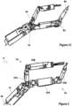
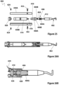
- FIGS. 1A-1C and 2 One embodiment of a robotic device 8 is depicted in FIGS. 1A-1C and 2 .
- This embodiment has a device body 10, a left arm 20, and a right arm 30, as shown in FIGS. 1A and 2 .
- Both the left and right arms 20, 30 are each comprised of 2 segments: an upper arm (or “first link” ) and a forearm (or “second link” ).
- the left arm 20 has an upper arm 20A and a forearm 20B
- the right arm 30 has an upper arm 30A and a forearm 30B.
- the device main body 10 can, in some embodiments, be coupled to an insertion rod 40.
- the various joints in the right arm 30 provide for various degrees of freedom. More specifically, the right shoulder (the joint at which the upper arm 30A is coupled to the device body 10) provides two degrees of freedom: shoulder pitch ⁇ 1 and shoulder yaw 82.
- the elbow joint (the joint at which the forearm 30B is coupled to the upper arm 30A) provides elbow yaw ⁇ 3, and the end effector on the distal end of the forearm 30B provides end effector roll ⁇ 4.
- the device 8 is configured to have a reduced profile and/or cross-section. That is, the shoulder joints (where the upper arms 20A, 30A couple with the body 10), are positioned within the longitudinal cross-section of the body 10 such that shoulder joints and the proximal ends of the upper arms 20A, 30A do not extend beyond or exceed that cross-section. Further, when the arms 20, 30 are positioned in a straight configuration such that the upper arms 20A, 30A and forearms 20B, 30B extend along the same axis (the elbows are not bent), no part of the arms 20, 30 extend beyond the longitudinal cross-section of the body 10. This minimal cross-section greatly simplifies insertion of the device 8 into an incision.
- the "longitudinal cross-section” is the cross-section of the body 10 as viewed when looking at the distal end or the proximal end of the body 10 such that one is looking along the longitudinal axis of the body 10.
- the device body 10 has a motor housing 50 that is configured to contain at least one motor (described below) and a master control board (not shown) or other processor configured to control various components and/or actions of the device.
- the device body 10 also has a gear housing 62 coupled to the motor housing 50.
- the housing 50 has a housing cover 52 that is configured to be coupleable to the housing 50 and to provide access to the at least one motor positioned within an internal portion of the housing 50.
- the housing cover 52 has an opening 53 defined in the portion of the housing cover 52 that covers the proximal end of the housing 50.
- the opening 53 is configured to receive an insertion rod 54 (also referred to as a "positioning rod” or “positioning component”).
- screws 56 or other fastening components are used to couple the rod 54 to the cover 52 as shown.
- the insertion rod 54 is used to advance the device 8 during insertion. In other implementations, it can also be used to position the device 8 within the patient's cavity during the procedure.
- the rod 54 will have communication and power wires (also referred to herein as “cables” or “connection components”) disposed in one or more lumens defined in the rod 54 that will operably couple the device 8 to an external controller (not shown).
- the external controller can be a personal computer, a joystick-like controller, or any other known controller that allows a user to operate the device 8.
- the connection components can also include one or more camera and/or lighting wires.
- the motor housing 50 is coupled to the gear housing 62 such that a portion of each of the motor assemblies 60A, 60B is positioned in the motor housing 50 and a portion is positioned in the gear housing 62.
- the motor housing 50 is coupled to the gear housing 62 with screws 44, 46 that are positioned through holes in the motor housing 50 and threadably coupled within holes in the gear housing 62.
- the housing cover 52 is removably coupled to the motor housing 50 with screws 48.
- the screws 48 are positioned through holes defined in the housing 50 and threadably coupled within holes in the housing cover 52.
- any known coupling mechanisms such as bolts or snap or friction fit mechanisms, can be used to removably couple the cover 52 to the housing 50.
- the device body 10 contains the two motor assemblies 60A, 60B.
- the two motor assemblies 60A, 60B actuate the movement of the left and right arms 20, 30, as will be described in further detail below.
- the body 10 can also contain a master control board (not shown) and a stereoscopic camera (not shown).
- the master control board controls the motors 60A, 60B.
- each of the two motor assemblies 60A, 60B is the actuator for a drive train with a three stage gear head. That is, the left motor assembly 60A is the actuator for a drive train coupled to the left arm 20, while the right motor assembly 60B is the actuator for a drive train coupled to the right arm 30. While the following description will focus on the right motor 60B and its drive train, it is understood that the left motor assembly 60A and its drive train will have similar components and operate in a similar fashion.
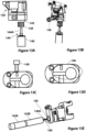
- the first stage of the three stage gear head is the gear head 60B-2 attached to the motor 60B-1 of the motor assembly 60B.
- the second stage is the spur gear set, which is made up of the motor gear 68 and the driven gear 96 as best shown in FIG. 9A .
- the motor gear 68 and the driven gear 96 are rotationally coupled to each other in the gear housing 62.
- the motor gear 68 and driven gear 96 are spur gears. Alternatively, they can be any known gears.
- the motor gear 68 is also known as a "first gear,” “drive gear,” or “driving gear.”
- the driven gear 96 is also known as a “second gear” or “coupling gear.”
- the third stage is the bevel gear set, which is made up of the housing bevel gear 92 and the link bevel gear 102.
- the housing bevel gear 92 and the link bevel gear 102 are rotationally coupled to each other as best shown in FIG. 9A . These components and gear sets will be discussed in detail below.
- the housing bevel gear 92 is also known as the “third gear,” “housing gear,” “second drive gear,” or “first shoulder gear.”
- the link bevel gear 102 is also know as the "fourth gear,” “link gear,” or “second shoulder gear.”
- both the right and left motor assemblies 60A, 60B are positioned at their distal ends into the gear housing 62.
- the right motor assembly 60B has a motor 60B-1 and a gearhead 60B-2.
- the gearhead 60B-2 is the first stage gear head and is operably coupled to the motor 60B-1.
- the motor assembly 60B has a motor shaft 67 operably coupled at the distal end of the assembly 60B.
- the motor shaft 67 has a flat surface 67A that creates a "D" configuration that geometrically couples the shaft 67 to the spur gear 68.
- the right motor assembly 60B is positioned in the right motor gear opening 69 of the gear housing 62, as best shown in FIG.
- the motor assembly 60B has a configuration or structure that allows for the assembly 60B to be geometrically coupled within the right motor gear opening 69.
- the gear housing 62 has a clamp 70 that can be used to retain the motor assembly 60B within the motor gear opening 69. That is, a threaded screw 66 or other coupling mechanism is positioned in the clamp 70 and threaded into the clamp 70, thereby urging the clamp 70 against the assembly 60B, thereby retaining it in place.
- the assemblies 60A, 60B can be secured to the housing 62 via adhesive or any other known coupling or securement mechanisms or methods.
- the gear housing 62 is coupled to a bearing housing 64.
- the bearing housing 64 is comprised of three housing projections 64A, 64B, 64C.
- the right driven spur gear assembly 96 is rotationally coupled to the bearing housing 64. More specifically, the right driven spur gear assembly 96 is rotationally retained in the bearing housing by the bearings 94, 98 as shown in FIG. 9A .
- the bearings 94, 98 are positioned in and supported by the bearing housing 64 and the gear housing 62.
- the spur gear assembly 96 is operably coupled to the housing bevel gear 92 such that the spur gear 96 drives the bevel gear 92. More specifically, the spur gear 96 is positioned over the proximal portion of the bevel gear 92, with the proximal portion having a flat portion or other configuration that rotationally couples the spur gear 96 to the bevel gear 92 such that the spur gear 96 and bevel gear 92 are not rotatable in relation to each other. Further, the bevel gear 92 is positioned between the first and second housing projections 64A and 64B and supported by bearings 94, 98. As best shown in FIG.
- the bearings 94, 98 and the spur gear 96 are secured to the gear 92 by screw 100, which is threadably coupled to the bevel gear 92.
- the bevel gear 92 is rotationally coupled to the first and second projections 64A, 64B.
- the spur gear 96 and bevel gear 92 are rotationally coupled to housing 62 and housing 64 by screws 80, 82 (as best shown in FIG. 8A ), which are threadably coupled to the housings 62, 64 such that the housings 62, 64 are coupled to each other.
- the bevel gear 92 is rotationally coupled to the link 102, which is operably coupled to the right arm 30 of the device 8 as described in further detail below.
- the link 102 couples the device body 10 to the right arm 30 such that actuation of the motor 60B results in actuation of some portion or component of the right arm 30.
- the link 102 is supported by bearings 90A, 90B, which are coupled to the housing 64 as best shown in FIGS. 9A and 9B .
- the right upper arm 30A is coupled to the device body 10. And in certain embodiments, the right upper arm 30A is more specifically coupled to the link 102 discussed above. As best shown in FIGS. 10A and 10B , the upper arm 30A is coupled to the device body 10 at the link 102.
- the upper arm 30A has a motor housing 128 configured to hold at least one motor and a housing cover 124 coupled to the housing 128.
- the housing cover 124 is coupled to the motor housing 128 by screws 126, which are threadably coupled to the motor housing 128 as shown. Alternatively, any mechanical coupling mechanisms can be used.
- the motor housing 128 is operably coupled to a spur gear housing 120 at each end of the motor housing 128 such that there are two spur gear housings 120 coupled to the motor housing 128.
- the housing 128 contains two motor and gear head assemblies 142, 143 and a local control board 132, which will be described in further detail below.
- the two assemblies 142, 143 are secured to the housing 128 with screws 130, which are threadably coupled to motor housing 128 as best shown in FIG. 10B .
- the local control board 132 is operably coupled to the motor housing 128 and housing cover 124 and controls the two motor assemblies 142, 143 in the housing 128.
- the board 132 is also operably connected to both of the motor assemblies 142, 143 within the housing 128 via flexible electrical ribbon cable (either FFC or FPC) 134, 136.
- the board 132 receives communications (such as commands and requests, for example) from the master control board (not shown) located in the device body 10 via the flexible electrical ribbon cable 134. Further, the board 132 also transmits, passes, or relays communications (such as commands and requests) from the master board to the next device component, which - in this embodiment - is the right forearm 30B via the flexible electrical ribbon cable 136.
- each of the local boards disclosed herein is “daisy chained” or wired together in a sequence in the device 8.
- daisy chain is intended to have its standard definition as understood in the art.
- the local boards are daisy chained together using flexible ribbon cable such as the cable 134, 136 such that the cable can transmit power, analog signals, and digital data.
- the use of a daisy chain configuration can create an electrical bus and reduce the number of wires required.
- the two motor assemblies 142, 143 are responsible for the right arm 30 shoulder yaw and elbow pitch as best shown in FIG. 1C .
- the two motor assemblies 142, 143 in the upper arm 30A as best shown in FIGS. 11B and 11C are substantially similar, so the right motor assembly 142 will be discussed in detail herein.
- the motor drive train has a three stage gear head. The first stage is the gear head 142B attached to the motor 142A in the motor assembly 142 (as best shown in FIG.
- the second stage is a spur gear set made up of the motor spur gear 138 and the driven spur gear 156
- the third stage is a bevel gear set made up of the bevel gear 152 and the driven bevel gear 170. All of these components will be described in further detail below.
- the motor assembly 142 has a drive shaft 144 that is operably coupled to the spur gear 138.
- the drive shaft 144 has a flat portion 144A that results in a D-shaped shaft, which helps to rotationally couple the spur gear 138 to the shaft 144.
- the spur gear 138 can be further coupled to the shaft 144 using a bonding material such as, for example, JB-Weld.
- the spur gear 138 can be coupled to the shaft 144 in any known fashion using any known mechanism.
- the motor assembly 142 is positioned within a lumen 145 defined in the spur gear housing 120.
- the assembly 142 can be coupled or otherwise retained within the lumen 145 using a clamping assembly 146 (as best shown in FIGS. 13C and 13D ). That is, once the motor assembly 142 is positioned within the lumen 145, the screw 140 can be urged into the hole, thereby urging the clamping assembly 146 against the motor assembly 142, thereby frictionally retaining the assembly 142 in the lumen 145.
- the assembly 142 can be secured to the housing 120 via adhesive or any other known coupling or securement mechanisms or methods.
- the second stage spur gear set is made up of the motor spur gear 138 and the driven spur gear 156.
- the two gears 138, 156 are rotationally coupled to each other within the spur gear housing 120 as shown.
- the driving bevel gear 152 is operably coupled with the driven spur gear 156, with bearings 154, 158 positioned on either side of the spur gear 156, thereby creating the spur/bevel assembly 150.
- the spur gear 156 is rotationally coupled to the bevel gear 152 such that neither the spur gear 156 nor the bevel gear 152 can rotate in relation to each other.
- the two gears 156, 152 are rotationally coupled using a D-shaped geometric feature.
- the spur gear 156 is translationally constrained by the supporting bearings 154, 158, which are preloaded through screw 160.
- the fully assembled assembly 150 can be positioned in the lumen 151 in motor housing 120.
- the third stage bevel gear set is made up of a drive bevel gear 152 and a link bevel gear 170.
- the drive bevel gear 152 is part of the spur/bevel assembly 150 and thus is operably coupled to and driven by the spur gear 156.
- link bevel gears 170A, 170B positioned at opposite ends of the upper arm 30A, as best shown in FIGS. 11A, 11B, and 11C .
- the link bevel gear 170A operably couples the upper arm 30A to the device body 10
- the link bevel gear 170B operably couples the upper arm 30A to the forearm 30B.
- the bearings 172, 174 support the link bevel gear 170.
- the bearings 172, 174 are supported by the bearing housing 176, which is made up of two housing projections 176A, 176B.
- the bearing housing 176 can apply a preload force to the bearings 172, 174.
- the housing projections 176A, 176B are secured to the motor housing 120 by screws 180, 182, which are threadably coupled through the motor housing 120 and into the housing projections 176A, 176B.
- upper arm 30A also applies to upper arm 20A as well. That is, in certain embodiments, the upper arm 30A and upper arm 20A are substantially the same.
- FIGS. 18A-21C depict one implementation of a grasper forearm component 200 (which could, of course, be the forearm 30B discussed and depicted above) that can be coupled to the upper arm 30A. More specifically, the forearm 30B has an opening 218 defined at a proximal end of the arm 200 that is configured to be coupled to the link bevel gear 170B as discussed above.
- This forearm 200 has a grasper end effector (also referred to herein as a "manipulation end effector”) 256 discussed in further detail below.
- the grasper forearm 200 has a motor housing 202 coupled to a gear housing 212.
- the two housings 202, 212 contain two motor assemblies 206, 208, which actuate rotation of the grasper end effector 256 and opening/closing of the grasper 256, as described in further detail below.
- the motor housing 202 also contains the local control board 210 and has a housing cover (also referred to as a "cap") 204 configured to removably cover the opening 205 that provides access to the interior of the motor housing 202.
- the cover 204 can be coupled to the housing 202 with screw 216.
- the screw 216 is threadably positioned into the opening 218 and thus can be threadably coupled to the link bevel gear 170 as discussed above, thereby rotationally coupling the forearm 200 to the upper arm 30A.
- the motor housing 202 and cover 204 are coupled to the gear housing 212 with screws 214, which are threadably coupled through openings in the housing 202 and cover 204 and into the gear housing 212.
- the local control board 210 can be the same or similar to the local control board 132 in the upper arm as described above.
- the board 210 is coupled to the local control board 132 via the flexible electrical ribbon cable 136 in the upper arm 30A as described above.
- the two motor assemblies 206, 208 are coupled to the gear housing 212 via clamps 222, 230. More specifically, the motor assembly 206 is coupled to the housing 212 with the clamp 222 as best shown in FIGS. 19A and 19B , while the motor assembly 208 is coupled to the housing with the clamp 230 as best shown in FIGS. 20A and 20B . Alternatively, the assemblies 206, 208 can be secured to the housing 212 via adhesive or any other known coupling or securement mechanisms or methods.
- the clamp 222 is coupled to the gear housing 212 with screws 224, which are threadably positioned through holes in the clamp 222 and into the gear housing 212.
- the clamp 222 secures the motor assembly 206 by frictional force applied by urging the clamp 222 against the housing 212 with the screws 224.
- the motor assembly 206 contains two parts: a motor 206B and gear head 206A.
- the gear head 206A is operably coupled to the motor 206B.
- a drive gear (which is also a "spur gear”) 220 is operably coupled to the shaft 207 extending from the motor assembly 206.
- the shaft 207 has a flat portion resulting in a "D shaped" geometry
- the gear 220 has a hole that mates that geometry, thereby ensuring that the shaft 207 and gear 220 are not rotatable in relation to each other when they are coupled.
- the gear 220 is also adhesively coupled to the shaft 207 with JB Weld or any known adhesive material.
- the gear 220 and shaft 207 can be coupled in any known fashion using any known coupling mechanism or configuration.
- the clamp 230 is urged toward the housing 212 with screw 232, thereby creating frictional retention of the motor assembly 208. As such, the clamp 230 can retain the assembly 208 in the housing 212.
- the motor assembly 208 has two parts: a motor 208A and a gear head 208B coupled to the motor 208A.
- a drive gear (which is also a "spur gear") 264 is operably coupled to the shaft 209 extending from the motor assembly 208.
- the shaft 209 has a flat portion resulting in a "d shaped" geometry, and the gear 264 has a hole that mates that geometry, thereby ensuring that the shaft 209 and gear 264 are not rotatable in relation to each other when they are coupled.
- the gear 264 is also adhesively coupled to the shaft 209 with JB Weld or any known adhesive material.
- the gear 264 and shaft 209 can be coupled in any known fashion using any known coupling mechanism or configuration.
- drive spur gear 264 is coupled in the gear housing 212 with driven spur gear 250, and actuation of the drive spur gear 264 (and thus the driven spur gear 250) causes the grasper end effector 256 to rotate.
- the drive spur gear 220 is coupled in the gear housing 212 with driven spur gear 248, and actuation of the drive spur gear 220 (and thus the drive spur gear 248) causes the grasper end effector 256 to move between its open and closed positions.
- the gear housing 212 has a bearing cover (also referred to as a "cap") 240, which is attached to the gear housing 212 by screws 242 which are threadably coupled through holes in the cover 240 and into the gear housing 212.
- the screws 242 can also be configured to apply a preload force to bearings 244, 246, 260, 252.
- the bearings 244, 246, 260, 252 are supported within the gear housing 212.
- Bearings 244, 246 support the driven spur gear 248 of the end effector actuation spur gear set 220, 248.
- the spur gear 248 has a lumen with internal threads formed in the lumen and thus can be threadably coupled to the grasper drive pin 254, which can be positioned at its proximal end in the lumen of the spur gear 248.
- the threads in the lumen of the spur gear 248 coupled to the threads on the drive pin 254 cause the drive pin 254 to translate, thereby causing the grasper links 256 to move between open and closed positions.
- translation of the drive pin 254 is transferred through a four bar linkage made up of links 262A, 262B and grasper links 256A, 256B.
- this actuation of the grasper 256 can be accomplished through any other known mechanisms such as a pin and slot or worm gear drive train.
- a pin 266 secures the four bar linkage 262A, 262B, 256A, 256B to the spur gear 250.
- the pin 266 is threadably coupled to spur gear 250.
- the bearings 260, 252 support the driven spur gear 250.
- the driven spur gear 250 is coupled to the grasper 256 such that when spur gear 250 is rotated, the grasper 256 is rotated.
- the spur gear 248 To rotate the grasper 256 without also actuating the grasper to move between its open and closed positions, the spur gear 248 must rotate in the same direction and at the same speed as the spur gear 250. That is, as described above, the drive pin 254 is rotationally coupled to spur gear 250 (otherwise translation of the pin 254 is not possible) such that when spur gear 250 is rotated (to cause the end effector to rotate), the drive pin 254 is also rotated.
- spur gear 248 if spur gear 248 is not also rotated in the same direction at the same speed as the spur gear 250, the drive pin 254 will translate, thereby causing the grasper 256 to open or close. As a result, to rotate the grasper 256 without opening or closing it, the spur gears 250 and 248 must rotate together.
- the spacer 258 can provide spacing between the bearings 246, 260 and can also transfer the preload force through each bearing within the assembly.
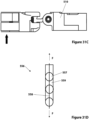
- FIGS. 22A-24C depict an alternative embodiment relating to a cautery forearm component 300 (which could, of course, be the forearm 30B discussed and depicted above) that can be coupled to the upper arm 30A. More specifically, as best shown in FIG. 22A , the forearm 300 has an opening 306 defined at a proximal end of the arm 300 that is configured to be coupled to the link bevel gear 170B as discussed above. In one implementation, a screw 308 secures or threadably couples the link bevel gear 170B to motor housing 302A.
- This forearm 300 has a cautery end effector 332 that can be a monopolar electrocautery device as discussed in further detail below.
- the forearm 300 is made up a motor housing 302 that is coupled to a gear housing 304.
- a motor assembly 320 is positioned within the motor housing 302 and gear housing 304.
- the motor housing 302 is actually made up of two housing components - a first motor housing component 302A and a second motor housing component 302B - that are coupled to each other to make up the housing 302.
- the first component 302A and second component 302B are secured to each other at least in part by the screw 310, which is inserted through holes in both components 302A, 302B and threadably coupled to both.
- the motor housing 302 is secured to the gear housing 304 via screws 312, which are positioned through holes in the motor housing 302 and into the gear housing 304.
- the motor assembly 320 is comprised of two parts: a motor 320B and a gear head 320A, which is operably coupled to the motor 320B.
- a drive gear (which is also a "spur gear") 324 is operably coupled to the shaft 322 extending from the motor assembly 320.
- the shaft 322 has a flat portion resulting in a "d shaped" geometry
- the gear 324 has a hole that mates that geometry, thereby ensuring that the shaft 322 and gear 324 are not rotatable in relation to each other when they are coupled.
- the gear 324 is also adhesively coupled to the shaft 322 with JB Weld or any known adhesive material.
- the gear 324 and shaft 322 can be coupled in any known fashion using any known coupling mechanism or configuration.
- the gear housing 304 has a housing cover (also referred to as a "housing cap”) 326 that is coupled to the distal portion of the gear housing 304 with screws 328 that are threadably coupled through holes in the cover 326 and into the gear housing 304.
- the housing cover 326 and screws 328 can, in some embodiments, apply a preload force to bearings 340, 342 positioned inside the housing 304 (as best shown in FIG. 24C ).
- the drive spur gear 324 is operably coupled in the gear housing 304 to the driven spur gear 336. As shown in FIG.
- the driven spur gear 336 is operably coupled to the cautery end effector 332 and is supported by bearings 340, 342.
- the bearings 340, 342 are translationally fixed to the driven spur gear 336 by a nut 338 that is threadably coupled to the spur gear 336.
- the nut 338 does not apply a preload to the bearings 340, 342.
- a spacer 344 is included to provide bearing spacing.
- the monopolar electrocautery end effector 332 is threadably coupled at a proximal end of the end effector 332 to the spur gear 336.
- electricity is transferred from the proximal tip 334 of the end effector 332 to the distal portion of the end effector 332 through a slip ring (not pictured) that is secured to the motor housing 302.
- the slip ring is secured to a configuration 314 formed in the motor housing 302 as shown in FIG. 22B .
- the distal end of the end effector 332 is used to cauterize tissue.
- the cautery forearm 300 has only one motor assembly 320 that has a two-stage gearhead.
- the first stage is the gear head 320A coupled to the motor 320B, and the second stage is the spur gear set made up of the drive spur gear 324 and the driven spur gear 336.
- the cautery forearm component 300 does not contain a local control board. Instead, the component 300 can have a flexible electrical ribbon cable (not shown) operably coupled to the motor that connects to the local control in the upper arm (such as the local control board 132 in FIG. 11A ). In one embodiment, the local control board in the upper arm (such as board 132, for example) can have one or more extra components to facilitate an additional motor. The single motor (not shown) in the cautery forearm component 300 can actuate rotation of the end effector 332.
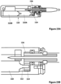
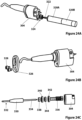
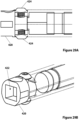
- FIGS. 25-29B depict yet another alternative embodiment of a cautery forearm component 400 (which could, of course, be the forearm 30B discussed and depicted above) that can be coupled to the upper arm 30A.
- This forearm 400 has a cautery end effector 402 that has an "inline" configuration that minimizes the overall cross-section of the forearm 400 and ultimately the robotic device to which it is coupled, thereby aiding in both surgical visualization and insertion.
- the inline configuration has a direct-drive configuration that enables the size of the forearm 400 to be reduced by almost half.
- the cautery end effector 402 is a removable cautery tip 402.
- the end effector 402 is removably coupled to the arm 400 at the drive rod 404. More specifically, in this embodiment, the end effector 402 has a lumen at its proximal end with threads formed on the inside of the lumen such that the threads 404A on the distal portion of the drive rod 404 can be threaded into the lumen in the end effector 402.
- the coupling of the end effector 402 and the drive rod 404 results in an electrical connection between the end effector 402 and the drive rod 404.
- a first slip ring 426 electrically couples the monopolar cautery generator (the power source for the end effector 402, which is not shown) to the motor coupler 410. More specifically, the first slip ring 426 is coupled to a wire 429 that is coupled to the generator (not shown), thereby electrically coupling the ring 426 to the generator. Further, the slip ring 426 is secured to the body portions 430A, 430B (as best shown in FIG. 25 and discussed in further detail below) such that the ring 426 does not rotate in relation to the body 430.
- the slip ring 426 is rotatably coupled to the motor coupler 410 such that the ring 426 and coupler 410 are electrically coupled and can rotate in relation to each other.
- the motor coupler 410 is threadably and electrically coupled to the drive rod 404.
- the cautery end effector 402 is coupled to the electrical cautery interface (also referred to herein as a "pin") 412.
- This pin 412 is coupled to the drive rod 404 via a second slip ring, which is positioned generally in the area identified as 428 in FIG. 26B , thereby ultimately resulting in an electrical connection between the end effector 402 and the first slip ring 426.
- the second slip ring 428 is secured to the drive rod 404 or is a part of the drive rod 404.
- the slip ring 428 can be a separate component.
- This electrical connection of the first slip ring 426 to the end effector 402 through the motor coupler 410 enables transfer of the electrical energy to the end effector 402 that is necessary for cauterization. This is explained further below.
- the coupling of the end effector 402 and the drive rod 404 is maintained by the friction of the threadable coupling of the two components, along with the deformability of the end effector 402, which reduces the amount of force applied to that coupling.
- the end effector 402 has an o-ring at its distal end that helps to create a seal at the coupling to the drive rod 404 that inhibits inflow of biological material.
- the end effector 402 can be non-removable. Instead, the end effector 402 can be integrated into the drive rod such that the need for the removable threaded connection would be eliminated. In such an embodiment, the second slip ring 428 could be replaced with a rigid electrical connection.
- two bearings 408A, 408B are positioned over a proximal portion of the drive rod 404 and help to provide support to the end effector 402.
- the shoulder 406 on the drive rod 404 help to maintain the position of the bearings 408A, 408B in relation to the drive rod 404.
- the motor coupler 410 is threadably coupled to threads 404B on the proximal end of the drive rod 404 and thus also helps to retain the bearings 408A, 408B in place on the drive rod 404.
- the electrical connection discussed above extends through all three components: the motor coupler 410, the drive rod 404, and the end effector 402.
- the pin 412 extending from the proximal portion of the end effector 402 makes the electrical connection of the three components possible.
- This configuration of the three components allows for easy removal of one end effector 402 and replacement with another end effector 402 that is positioned such that the electrical connection is re-established by the simple threaded coupling of the new end effector 402 to the drive rod 404.
- bearings 408A, 408B can be replaced with other support components.
- One example would be bushings.
- the motor coupler 410 couples the motor assembly 414 to the end effector 402 through the drive rod 404. More specifically, the motor coupler 410 is coupled with the motor shaft 416 such that the coupler 410 is positioned over the shaft 416.
- the motor shaft 416 has a flat portion 416A on the shaft that creates a "D-shaped" configuration and the motor coupler 410 has a corresponding "D-shaped” configuration that mates with the shaft 416 such that the shaft 416 and coupled 410 are not rotatable in relation to each other when they are coupled.
- the motor coupler 410 has two portions with different diameters: a large portion 410A and a small portion 410B.
- the small portion 410B is sized to receive the first slip ring 426 discussed above that creates the necessary electrical connection. That is, as discussed above, when positioned over the small portion 410B of the motor coupler 410, the slip ring 426 can provide a constant clamping force on the motor coupler 410 that maintains the electrical connection between the motor coupler 410 and the motor shaft 416 during rotation.
- This type of connection (the slip ring) allows for infinite rotation without twisting of any wires.
- the coupling in some implementations is reinforced or further secured with an adhesive.
- the adhesive could be a Loctite ® adhesive or any other known adhesive for use in medical device components.
- the proximal end of the forearm 400 has a coupling component 420 that allows for coupling the forearm 400 to the rest of the surgical system with which the forearm is incorporated.
- the coupling component 420 would be coupled to the upper arm 30A.
- the coupling component 420 is coupled to the proximal portion of the forearm 400 with two screws 424 that are positioned through holes in the forearm 400 and into a portion of the coupling component 420 as shown.
- the coupling component 420 has an opening 422 defined in the component 420 (as best shown in FIG. 29B ) that couples to the appropriate component of the surgical system.
- the opening 422 is a rectangular-shaped opening 422, but it is understood that it could be any configuration of any type of coupling component or mechanism, depending on the system to which the forearm 400 is being coupled.
- the coupling component 420 can be eliminated in those embodiments in which the forearm 400 is an integral part of the upper arm of a device or in any embodiment in which there is no forearm.
- the body 430 of the forearm 400 is made up of two body portions (also referred to as "shells") 430A, 430B.
- the two portions 430A, 430B are coupled together with the screws 432 and the aforementioned screws 424.
- each of the two body portions 430A, 430B have internal features as best shown in FIG. 26A that help to retain the motor assembly 414, bearings 408A, 408B, and other internal components in position with respect to each other inside the body 430.
- the interface of the portions 430A, 430B may have mating lip and groove configurations to provide a fluidic seal at the coupling of the two portions 430A, 430B.
- FIGS. 30-39B Another embodiment of a robotic device 500 is depicted in FIGS. 30-39B .
- This embodiment has a device body 510, a left arm 520, and a right arm 530, as shown in Figure 30 .
- Both the left and right arms 520, 530 are each comprised of 2 segments: an upper arm (or "first link") and a forearm (or "second link”).
- the left arm 520 has an upper arm 520A and a forearm 520B
- the right arm 530 has an upper arm 530A and a forearm 530B.
- the robotic device 500 is similar in some respects to the device embodiment described above and depicted in FIGS. 1A-2 .
- the current device 500 is unique because of its "clutch-like" joint configuration as described in detail below.
- the device 500 needs to be very flexible to navigate the natural curvature of the natural orifice.
- the clutch-like joint configuration at each joint in this device 500 provides the device 500 with the necessary flexibility.
- this device 500 will be locally controlled by a control system similar to the system described above with respect to the previous embodiments.
- the clutch-like configuration is best shown in FIGS. 32A and 32B .
- the overall joint design is fairly similar to the joint design of the embodiments described above.
- the drive bevel gear 560 has a portion 562 of the gear 560 that has no teeth.
- the tooth-free portion 562 creates the clutch-like configuration. That is, when the drive bevel gear 560 is positioned such that the tooth-free portion 562 is in contact with or adjacent to the driven gear 564 such that no teeth are engaged, the overall joint 566 is free to move and thus has flexibility that can be helpful during insertion.
- this embodiment can also have one or more rubber band-like components (also referred to herein as “elastomers” or “elastic bands”) 550 that can be used to keep each joint stabilized and thus each arm positioned to keep the robotic device 520 as compact as possible during insertion.
- the band(s) 550 can also keep the arms in the correct position for engagement of the bevel gears. More specifically, the device body 510 and the two upper arms 520A, 530A have a channel 552 formed on a top portion of each component as shown in FIG. 31B that is configured to receive the elastic band(s) 550.
- the elastic band (or bands) 550 applies forces to the arms 520A, 530A that urge the arms 520A, 530A together as shown by the arrows in FIG. 31B while also urging both arms upward as shown by the arrow in FIG. 31C .
- this clutch-like configuration could also be used for homing if the positioning of the arms 520, 530 is lost (that is, the joint positions are unknown).
- each of the drive bevel gears could be positioned so that they are not engaged, whereby the joint positions of the device 500 are known once again. In this embodiment, no additional redundant position sensors would be needed.
- FIG. 31D depicts one exemplary embodiment of a mechanically-activated link 556.
- the link 556 becomes flexible when a small force F is applied to the cable 558, thereby reducing the friction between the balls 557 and sockets 559 in the link 556 and thus creating flexibility in the link 556. in contrast, when a large force F is applied to the cable 558, friction is increased between the balls 557 and sockets 559 and the link 556 becomes more rigid.
- FIG. 33 depicts the various degrees of freedom of the various joints of the two arms 520, 530.
- the left arm 520 has four degrees of freedom, while the right arm 530 has five degrees of freedom. More specifically, moving from the proximal end of the right arm 530 to the distal end, the right arm 530 has shoulder pitch ( ⁇ 1), shoulder yaw ( ⁇ 2), elbow roll ( ⁇ 3), elbow yaw ( ⁇ 4), and end effector roll ( ⁇ 5).
- the left arm 520 has shoulder pitch, shoulder yaw, elbow yaw, and end effector roll, but no elbow roll.
- any other known kinematic configuration could also be used.
- the multiple degrees of freedom for each arm results in more dexterous arms for more precision operations.
- FIG. 34 depicts the key components that make up the joint (also referred to as an "elbow joint") between the upper arm 530A and the forearm 530B of the right arm 530.
- the upper arm 530A has a motor assembly 600 that includes a motor, an encoder, and a gearhead.
- the distal end of the motor assembly 600 is positioned in and coupled to the gear housing 602.
- the motor assembly 600 has a flat portion along an exterior portion of the assembly 600 that creates a "D-shaped" configuration that matches a D-shaped configuration of a lumen in the gear housing 602 such that the assembly 600 and housing 602 cannot rotate in relation to each other when the assembly 600 is positioned in the lumen.
- an adhesive can also be used to further secure the assembly 600 and housing 602.
- the motor assembly 600 has a motor shaft 600A extending from the distal end of the assembly 600.
- the shaft 600A can be coupled to the motor spur gear 604 such that the spur gear 604 is positioned over the shaft 600A.
- the shaft 600A has a flat portion that results in a "D-shaped configuration that matches a "D-shaped" configuration of the lumen in the spur gear 604 such that when the spur gear 604 is positioned over the shaft 600A, neither component can rotate in relation to the other.
- the motor spur gear 604 couples or mates with the driven spur gear 606 when the two gears are properly positioned in the gear housing 602 such that rotation of the motor spur gear 604 rotates the driven spur gear 606.
- the driven spur gear 606 is coupled to the output link 608 such that actuation of the motor assembly 600 causes the output link 608 to rotate. More specifically, the driven gear 606 is positioned over the proximal end of the output link 608. In one embodiment, a portion of the proximal end of the output link 608 has a flat portion that results in a "D-shaped" configuration as described with respect to other components above, thereby resulting in the output link 608 and spur gear 606 being coupled such that they are not rotatable in relation to each other.
- a screw 610 is threadably coupled to the output link 608 and secures the spur gear 606 on the output link 608, along with the bearings 612, 614, while also translationally securing the output link 608.
- the bearings 612, 614 can constrain and support the output link 608 and are supported within the gear housing 602.
- the components are retained in the gear housing 602 with the help of the housing cover 616, which is secured to the housing 602 with the help of screws 618, which also apply a preload force through the gear housing cover 616.
- the screw 620 helps to secure an elastic band between the upper arm 530A and forearm 530B, as described above.
- FIG. 35 depicts the forearm 530B and end effector 630 of the right arm 530.
- the end effector 630 is another implementation of a monopolar electrocautery device 630.
- the forearm 530B has a motor housing 632 that is configured to hold the motor assembly (not shown) and also contains the slip ring 638, which is secured in the housing 632. It is understood that the motor assembly and associated drive train are substantially similar to the same components in the upper arm as described above.
- the motor spur gear 634 is operably coupled to the driven spur gear 636 in the motor housing 632.
- the driven gear 636 is supported and constrained by bearing 640 and bushing 642, which prevents translation of the driven gear 636.
- the driven gear 636 is threadably coupled to the removable end effector 630 via the threads on the distal portion of the gear 636.
- the end effector 630 is electrically coupled to the slip ring 638.
- the forearm 530B is fluidically sealed such that external fluids (such as body fluids, for example) are prevented from entering the internal portions of the forearm 530B.
- One component that helps to fluidically seal the forearm 530B is a gasket 644, which is positioned between the housing 632 and the housing cover 646 such that the screws 648 that secure the housing cover 646 to the housing 632 also secures the gasket 644 to the bushing 642.
- the gasket 644 is made of soft urethane or silicon.
- the gasket 644 is made of any material that can help to fluidically seal the housing 632.
- FIGS. 36-39B depict the forearm 520B and end effector 650 of the left arm 520.
- the end effector 650 is another implementation of a grasper component (also referred to herein as a "tissue manipulation component” or “tissue manipulator”) 650.
- the forearm 520B has two motor assemblies: the rotation motor assembly 652 and the grasper motor assembly 654.
- the rotation motor assembly 652 can cause the forearm 520B to rotate.
- the grasper motor assembly 654 can cause the grasper 650 to move between its open and closed positions.
- the rotation motor assembly 652 has a motor, an encoder, and an integrated gear head. Further, the assembly 652 has a motor shaft 656 that couples to the motor spur gear 658. According to one implementation, the shaft 656 has a flat portion 656A that results in the shaft 656 having a "D-shaped" configuration that mates with a "D-shaped" lumen defined in the spur gear 658. As such, the shaft 656 and gear 658 are coupled such that neither component can rotate in relation to the other.
- a portion of the motor assembly 652 and the motor spur gear 658 are positioned in the proximal gear housing 660, which also houses the driven spur gear 662 such that the motor spur gear 658 and driven spur gear 662 are rotatably coupled to each other when positioned in the housing 660.
- the motor assembly 652 is coupled to the housing 660, and in certain implementations, the assembly 652 is geometrically and/or adhesively secured to the housing 660. Actuation of the motor assembly 652 causes rotation of the motor spur gear 658, which causes rotation of the driven spur gear 662.
- the driven spur gear 662 is operably coupled to the output link 664, which is coupled to the upper arm 520A and thus is part of the joint between the upper arm 520A and forearm 520B. As shown in FIG. 36 , the driven spur gear 662 and two bearings 666, 668 are positioned on the output link 664 such that the bearings 666, 668 are supported within the proximal gear housing 660 and provide some support and constraint to the output link 664.
- a screw 670 is coupled to the output link 664 and helps to secure the gear 662 and bearings 666, 668 to the link 664 while also translationally constraining the link 664.
- the output link 664 has a flat portion 664A that creates a "D-shaped" configuration that mates with a D-shaped lumen defined in the driven spur gear 662 such that the gear 662 and link 664 cannot rotate in relation to each other when the gear 662 is positioned on the link 664.
- the housing 660 also has a housing cover 672 that is positioned over the opening in the housing 660 that contains the gears 658, 662.
- the cover 672 is secured in place by screws 674 and thereby applies a preload force to the bearings 666, 668.
- the housing also has an additional screw 676 that can be used to secure or otherwise constrain an elastic band that is coupled to both the upper arm 520A and the forearm 520B to stabilize the arms as described above.
- the housing 660 is configured to be fluidically sealed such that no liquid can gain access to any interior portions of the housing 660.
- the grasper motor assembly 654 has a motor, an encoder, and an integrated gear head. Further, the assembly 654 has a motor shaft 680 that couples to the motor spur gear 682. According to one implementation, the shaft 680 has a flat portion 680A that results in the shaft 680 having a "D-shaped" configuration that mates with a "D-shaped" lumen defined in the spur gear 682. As such, the shaft 680 and gear 682 are coupled such that neither component can rotate in relation to the other.
- a portion of the motor assembly 654 and the motor spur gear 682 are positioned in the distal gear housing 684, which also houses the driven spur gear 686 such that the motor spur gear 682 and driven spur gear 686 are rotatably coupled to each other when positioned in the housing 684.
- the motor assembly 654 is coupled to the housing 684, and in certain implementations, the assembly 654 is geometrically and/or adhesively secured to the housing 684. Actuation of the motor assembly 654 causes the grasper 650 to move between its open and closed positions, as described in detail below.
- the driven spur gear 686 is operably coupled to a push/pull mate 688, which is coupled to the grasper 650. More specifically, the driven spur gear 686 and two bearings 690, 692 are positioned on a threaded rod 694 extending from the push/pull mate 688 such that the bearings 690, 692 are supported within the distal gear housing 684 and provide some support and constraint to the driven gear 686.
- the gear 686 is threadably coupled to the rod 694.
- a housing cover 702 is configured to cover the opening in the gear housing 684 and thereby applies a preloading force to bearings 690, 692 via screws 704, 708 that are threadably coupled through the cover 702 and into the housing 684.
- the housing 684 also has a gasket or seal 710 that fluidically seals against the push/pull mate 688, thereby preventing any fluids from entering the interior of the housing 684.
- the seal 710 is made of soft urethane or silicon or any other known material for use in creating a fluidic seal.
- the push/pull mate 688 When the driven spur gear 686 rotates, the push/pull mate 688 translates, because the push/pull mate 688 is rotationally constrained to the grasper housing 696. More specifically, as best shown in FIGS. 38A and 38B , the push/pull mate 688 has a projection 689 that extends away from the push/pull mate 688 at 90 degrees in relation to the longitudinal axis of the forearm 520B. As such, the projection 689 is positioned in the housing 696 such that the push/pull mate 688 cannot rotate in relation to the housing 696.
- the grasper 650 is removably coupled to the push/pull mate 688 via a ball and socket coupling, with the ball 698 positioned at a proximal end of the replaceable grasper 650.
- the translational motion of the push/pull mate 688 is transferred to the grasper 650 jaws such that the jaws move between open and closed positions.
- the grasper 650 is geometrically and adhesively constrained to the grasper mate 700, which is geometrically constrained to the grasper housing 696.
- the grasper 650 and the grasper mate 700 are configured to be removably mateable to the distal end of the grasper housing 696 and the push/pull mate 688 as described above.
- the grasper 650 can be easily coupled for use and just as easily removed and replaced with another end effector.
- the grasper end effector 650 could be replaced with other known manipulation devices such as, but not limited to, other toothed graspers, bipolar electrocautery devices, clip appliers, shears, ultrasonic sealers, and the like.
- the end effector 650 can be secured to the housing 696 with an elastic band 712 as shown in FIG. 39B .
- any other type of band or retention device or mechanism can be used.
- the various in vivo robotic devices disclosed herein and other such devices are intended to be inserted into and positioned inside a cavity inside a patient, such as, for example, the peritoneal cavity.
- Various devices can be used to achieve the insertion of the device into the cavity.
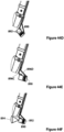
- FIGS. 40A-45 depict various examples of such insertion devices.
- FIGS. 40A , 41A, and 41B depict an insertion device 800 having an insertion tube 802 defining an insertion chamber 804, an insertion port 806, and a proximal tube cover 808.
- a robotic device 810 (such as, for example, any of the device embodiments discussed above), can be positioned inside the insertion chamber 804 and coupled to an insertion rod 812 that is positioned through the proximal tube cover 808.
- the device 800 can be positioned against an incision in a patient that accesses the target cavity such that the insertion port 806 is positioned against or in the incision.
- a user can use the insertion rod 812 to urge the device 810 out of the chamber 804 through the port 806 and into the patient's cavity.
- the robotic device 810 can be positioned inside the insertion tube 802 and magnetically coupled to a handle 824 positioned along an external portion of the tube 802 (as shown in FIG. 40B-1 ).
- the handle 824 can be used to introduce the robotic device 810 into the abdominal cavity and secure the device 810 to the abdominal wall through a magnetic coupling.
- the handle 824 can be urged distally along the outer surface of the tube 802, thereby urging the device 810 via magnetic forces in a distal direction as well such that the device 810 is urged out of the distal end of the tube 802 as best shown in FIG.40B-2 .
- the handle 824 can then be urged to the end of the tube 802 such that the arms of the device 810 fully exit the chamber 804 as best shown in FIG. 40B-3 and further such that the entire device 810 exits the chamber 804 and is positioned in the cavity using the handle 824 (wherein the handle 824 is positioned outside the patient's body) as best shown in FIG. 40B-4 .
- This insertion method can allow the orifice or insertion tube 802 to remain open for the duration of the surgical procedure.
- the orifice or insertion tube 802 can be used by other surgical devices as well, such as for specimen removal, for example.
- the magnetic coupling can allow the robotic device 810 to access a larger area of the abdominal cavity with different platform orientations.
- a channel could be created within the orifice or insertion tube 802 that can pass the communication and power tether to the robotic device 810.
- the insertion tube 802 is comprised of a single rigid and/or flexible tubular structure.
- the tube 802 is not limited to a tubular configuration and could have any known shape that could contain a robotic device for insertion into a patient's cavity.
- the cross-section of the tube 802 could have a rectangular or oval shape.
- the insertion tube 802 can be flexible.
- the flexible tube 802 (with the robotic device housed within) could be coupled to the port 806.
- the abdominal cavity is insufflated and the flexible tube 802 becomes semirigid as a result of the insufflation, like a balloon full of air.
- the robotic device is then inserted and, in one example, the flexible tube 802 collapses at a point parallel to the coupling of the insertion rod to the device, reducing the external size of the tube 802.
- a pressure release valve would be needed to account for the change in volume.
- FIGS. 42A and 42B depict the proximal tube cover 808.
- the cover 808 has a tube mate 850 coupled to the insertion tube 802.
- the tube mate 850 is geometrically and/or adhesively secured to the tube 802.
- the tube mate 850 is coupled at its opposite end to a housing 852.
- the tube mate 850 and housing 852 are coupled with screws 854.
- any known coupling mechanisms or methods can be used.
- a gasket 856 is positioned between the tube mate 850 and housing 852.
- a bushing 864 is positioned in and secured to the housing 852.
- the bushing 864 can be mated with the insertion rod 812 described above such that the rod 812 can move longitudinally with smooth linear motion.
- the housing 852 is coupled to a seal cap 858 via screws 860, and a gasket 862 and a seal 866 are positioned between the housing 852 and cap 858.
- the seal 866 creates a dynamic seal between the insertion rod 812 and the seal 866 to prevent the loss of insufflation of the abdominal cavity as the rod 812 is moved back and forth during a procedure.
- FIG. 43 depicts one implementation of the insertion port 806.
- the port 806 includes a insertion cone 880 and a tube mate 882.
- the tube mate 882 is coupled to the insertion tube 802.
- the tube mate 882 can be geometrically and/or adhesively coupled to the tube 802.
- the tube mate 882 is coupled to the insertion cone 880 with screws 884.
- a gasket 886 is positioned between the tube mate 882 and the insertion cone 880.
- the insertion cone 880 is not limited to conical geometry. That is, the insertion cone 880 could also have a tubular configuration or any other known configuration so long as the component could still operate as a port.
- any of the robotic devices disclosed or contemplated herein can be manually inserted into the abdominal cavity through the advancement of an insertion rod (such as, for example, the insertion rods 40, 812 described above) or a magnet.
- any such robotic device (such as robotic device 8, 810) can be robotically inserted into the abdominal cavity through the use of a robotic arm.
- the insertion procedure could be performed by the surgeon or autonomously.
- the robotic devices such as devices 8, 810 have a "sweet spot" or robotic workspace volume with high dexterity and manipulability. The use of a robotic arm can expand this workspace volume such that the volume includes the entire abdominal cavity.
- a "soft boundary" can be created between the workspace boundary, or limits, and the "sweet spot" of the workspace. That is, if the device crosses the soft boundary, the system has a sensor or other mechanism that is triggered such that the system actuates the external robotic arm to automatically and/or autonomously grossly position the robotic device back to the "sweet spot" of the workspace.
- Such repositioning operation can also be done manually or robotically under surgeon supervision. Autonomous gross positioning could eliminate the bed side assistant and human errors that commonly occur between the surgeon and assistant relating to positioning of the robotic device.
- insertion device 800 can have cameras (also referred to herein as “visualization devices” ) .
- the camera examples disclosed herein allow the user to view the device during insertion into and use in the patient's cavity.
- a camera 814 is housed within the insertion port 806.
- the camera 814 is a 3 MM CMOS camera 814.
- the vision cone 820 (the area captured by the camera 814 such that a user can see that area on the display) achieved by the camera 814 is shown.
- the camera 814 is coupled to a connection component 816 that couples the camera 814 to a monitor 818 or other type of display.
- Light in this example, is provided by LED lights 822 positioned on the distal end of the insertion port 806. Alternatively, any known lights that can be used with a medical device to illuminate a surgical space for viewing with a camera can be used.
- FIGS. 44A-44F depict another example of a camera 890 for use with certain examples of the insertion device 800.
- the camera 890 has lights 892 coupled to the camera 890.
- the camera 890 is coupled to the device 800 with a four-bar linkage 896 made up of four bars (or "links" ) 896A, 896B, 896C, 896D. That is, the four bars 896A, 896B, 896C, 896D can be manipulated by a user to move the camera 890 out of the cone 880 and position it to view the robotic device during insertion and use as shown in the figures.
- the vision cone 894 provides a schematic depiction of the area captured by the camera 890 in one embodiment.
- This configuration allows for a larger camera (such as, for example, a high definition camera) to be housed in the insertion cone 880 prior to insertion of the device (when the device is not positioned in or through the cone 880) and then moved out of the cone 880 during use. That is, once the port 806 is attached to the incision site and the cavity is insufflated, the camera 890 can be deployed via the four-bar linkage 896. This positioning of the camera in the cone 880 and then moving it out of the cone allows for the robotic device to always be under visualization during insertion.
- a larger camera such as, for example, a high definition camera
- any other known actuation device or mechanism could be used to deploy the camera.
- One such further example is a preformed shape memory alloy or the like.
- the camera 890 is a USB webcam.
- FIGS. 45A-45D depict yet another camera implementation.
- the camera 900 is coupled to a linkage 902 that is coupled to an exterior portion of the insertion cone 880. More specifically, the linkage 902 is made up of two links 902A, 902B, and the camera 900 is coupled to the link 9028.
- the link 902A is pivotally coupled to the insertion cone 880, and the link 9028 is pivotally coupled to the link 902A.
- the links 902A, 9028 are configured such that the camera 900 and links 902A, 9028 form a portion of the cone 880.
- the links 902A, 9028 are extended so that the camera 900 is in a position to capture images of the surgical area.
- the lights can be coupled to the link 9028 or link 902A (or both) to illuminate the viewing area.
- any of the camera, examples disclosed above can also have a zoom lens package or mechanical translation parallel to the axis of the vision cone via a linear actuator.
Landscapes
- Health & Medical Sciences (AREA)
- Surgery (AREA)
- Engineering & Computer Science (AREA)
- Life Sciences & Earth Sciences (AREA)
- Biomedical Technology (AREA)
- Robotics (AREA)
- Nuclear Medicine, Radiotherapy & Molecular Imaging (AREA)
- Heart & Thoracic Surgery (AREA)
- Medical Informatics (AREA)
- Molecular Biology (AREA)
- Animal Behavior & Ethology (AREA)
- General Health & Medical Sciences (AREA)
- Public Health (AREA)
- Veterinary Medicine (AREA)
- Manipulator (AREA)
Claims (9)
- Robotische Vorrichtung (810), die Folgendes umfasst:(a) einen Vorrichtungskörper (10), umfassend:(i) ein erstes Getriebe (60B-2), positioniert an einem distalen Ende des Vorrichtungskörpers; und(ii) ein zweites Getriebe (60B-2), positioniert an einem distalen Ende des Vorrichtungskörpers;(b) einen ersten Arm (20/30), wirkgekoppelt mit dem ersten Getriebe an einem ersten Schultergelenk, wobei der erste Arm Folgendes umfasst:(i) ein erstes Oberarmsegment (20A/30A), umfassend ein erstes Armmotorgehäuse (128) und eine erste lokale Steuerplatine (132), angeordnet innerhalb des ersten Armmotorgehäuses;(ii) ein erstes Unterarmsegment (20B/30B);(iii) einen ersten Endeffektor (256); und(iv) mindestens zwei erste Armmotoren (142, 143, 206, 208), angeordnet innerhalb des ersten Armmotorgehäuses und wirkgekoppelt mit der ersten lokalen Steuerplatine, wobei die mindestens zwei zweiten Armmotoren angeordnet sind zum Betätigen von Schultergierung und Ellbogengierung,
wobei das erste Oberarmsegment und das erste Unterarmsegment kolinear sind, wenn der erste Arm in der geraden Auslegung ausgestreckt ist; und(c) einen zweiten Arm (20/30), wirkgekoppelt mit dem zweiten Getriebe an einem zweiten Schultergelenk, wobei der zweite Arm Folgendes umfasst:(i) ein zweites Oberarmsegment (20A/30A), umfassend ein zweites Armmotorgehäuse (128) und eine zweite lokale Steuerplatine (132), angeordnet innerhalb des zweiten Armmotorgehäuses;(ii) ein zweites Unterarmsegment (20B/30B);(iii) einen zweiten Endeffektor (256); und(iv) mindestens zwei zweite Armmotoren (142, 143, 206, 208), angeordnet innerhalb des zweiten Armmotorgehäuses und wirkgekoppelt mit der zweiten lokalen Steuerplatine, wobei die mindestens zwei zweiten Armmotoren angeordnet sind zum Betätigen von Schultergierung und Ellbogengierung,
wobei das zweite Oberarmsegment und das zweite Unterarmsegment kolinear sind, wenn der zweite Arm in der geraden Auslegung ausgestreckt ist. - Robotische Vorrichtung nach Anspruch 1, wobei der Vorrichtungskörper erste, zweite und dritte Gehäusevorsprünge (64A, 64B, 64C) umfasst, die am distalen Ende des Vorrichtungskörpers angeordnet sind, wobei das erste Getriebe zwischen dem ersten und dem zweiten Gehäusevorsprung angeordnet ist und das zweite Getriebe zwischen dem zweiten und dem dritten Gehäusevorsprung angeordnet ist.
- Robotische Vorrichtung nach einem der vorhergehenden Ansprüche, wobei der erste Arm (20/30) innerhalb einer Kammer (804) positionierbar ist, wenn der erste Arm (20/30) in der geraden Auslegung ausgestreckt ist, und wobei der zweite Arm (20/30) innerhalb der Kammer (804) positionierbar ist, wenn der zweite Arm (20/30) in der geraden Auslegung ausgestreckt ist.
- Robotische Vorrichtung nach einem der vorhergehenden Ansprüche, wobei das erste Getriebe ausgelegt ist zum Drehen um eine erste Achse parallel zu einer Länge des Vorrichtungskörpers, und wobei ferner das zweite Getriebe ausgelegt ist zum Drehen um eine zweite Achse parallel zur Länge des Vorrichtungskörpers.
- Robotische Vorrichtung nach einem der vorhergehenden Ansprüche, wobei der Vorrichtungskörper mit einer Stützstange wirkgekoppelt ist.
- Robotische Vorrichtung nach einem der vorhergehenden Ansprüche, wobei das erste Getriebe (560) einen zahnfreien Teil (562) umfasst und wobei das zweite Getriebe einen zahnfreien Teil (562) umfasst.
- Robotische Vorrichtung nach Anspruch 6, ferner umfassend ein elastisches Band (550), wirkgekoppelt mit dem Vorrichtungskörper und dem ersten (520A) und dem zweiten (530A) Arm, wobei das elastische Band dazu ausgelegt ist, den ersten und den zweiten Arm zusammen hin zur geraden Auslegung zu zwingen.
- Robotische Vorrichtung nach einem der vorhergehenden Ansprüche, wobei das erste Unterarmsegment ein erstes Unterarmmotorgehäuse (204) und eine lokale Steuerplatine (210) am ersten Unterarm umfasst.
- Robotische Vorrichtung nach einem der vorhergehenden Ansprüche, wobei das zweite Unterarmsegment ein zweites Unterarmmotorgehäuse (204) und eine lokale Steuerplatine des zweiten Unterarms (210) umfasst.
Priority Applications (1)
| Application Number | Priority Date | Filing Date | Title |
|---|---|---|---|
| EP23174114.1A EP4234185A3 (de) | 2012-06-22 | 2013-03-15 | Robotische chirurgische vorrichtungen mit lokaler steuerung |
Applications Claiming Priority (6)
| Application Number | Priority Date | Filing Date | Title |
|---|---|---|---|
| US201261663194P | 2012-06-22 | 2012-06-22 | |
| EP13806521.4A EP2864086B1 (de) | 2012-06-22 | 2013-03-15 | Robotische chirurgische vorrichtungen mit lokaler steuerung |
| EP20152984.9A EP3680071B1 (de) | 2012-06-22 | 2013-03-15 | Robotische chirurgische vorrichtungen mit lokaler steuerung |
| PCT/US2013/032056 WO2013191773A1 (en) | 2012-06-22 | 2013-03-15 | Local Control Robotic Surgical Devices and Related Methods |
| EP18189171.4A EP3424651B1 (de) | 2012-06-22 | 2013-03-15 | Robotische chirurgische vorrichtungen mit lokaler steuerung |
| EP17157604.4A EP3189948B1 (de) | 2012-06-22 | 2013-03-15 | Robotische chirurgische vorrichtungen mit lokaler steuerung |
Related Parent Applications (4)
| Application Number | Title | Priority Date | Filing Date |
|---|---|---|---|
| EP18189171.4A Division EP3424651B1 (de) | 2012-06-22 | 2013-03-15 | Robotische chirurgische vorrichtungen mit lokaler steuerung |
| EP20152984.9A Division EP3680071B1 (de) | 2012-06-22 | 2013-03-15 | Robotische chirurgische vorrichtungen mit lokaler steuerung |
| EP13806521.4A Division EP2864086B1 (de) | 2012-06-22 | 2013-03-15 | Robotische chirurgische vorrichtungen mit lokaler steuerung |
| EP17157604.4A Division EP3189948B1 (de) | 2012-06-22 | 2013-03-15 | Robotische chirurgische vorrichtungen mit lokaler steuerung |
Related Child Applications (1)
| Application Number | Title | Priority Date | Filing Date |
|---|---|---|---|
| EP23174114.1A Division EP4234185A3 (de) | 2012-06-22 | 2013-03-15 | Robotische chirurgische vorrichtungen mit lokaler steuerung |
Publications (2)
| Publication Number | Publication Date |
|---|---|
| EP3943255A1 EP3943255A1 (de) | 2022-01-26 |
| EP3943255B1 true EP3943255B1 (de) | 2023-06-14 |
Family
ID=49769187
Family Applications (6)
| Application Number | Title | Priority Date | Filing Date |
|---|---|---|---|
| EP23174114.1A Pending EP4234185A3 (de) | 2012-06-22 | 2013-03-15 | Robotische chirurgische vorrichtungen mit lokaler steuerung |
| EP18189171.4A Active EP3424651B1 (de) | 2012-06-22 | 2013-03-15 | Robotische chirurgische vorrichtungen mit lokaler steuerung |
| EP21194189.3A Active EP3943255B1 (de) | 2012-06-22 | 2013-03-15 | Robotische chirurgische vorrichtungen mit lokaler steuerung |
| EP17157604.4A Not-in-force EP3189948B1 (de) | 2012-06-22 | 2013-03-15 | Robotische chirurgische vorrichtungen mit lokaler steuerung |
| EP20152984.9A Active EP3680071B1 (de) | 2012-06-22 | 2013-03-15 | Robotische chirurgische vorrichtungen mit lokaler steuerung |
| EP13806521.4A Not-in-force EP2864086B1 (de) | 2012-06-22 | 2013-03-15 | Robotische chirurgische vorrichtungen mit lokaler steuerung |
Family Applications Before (2)
| Application Number | Title | Priority Date | Filing Date |
|---|---|---|---|
| EP23174114.1A Pending EP4234185A3 (de) | 2012-06-22 | 2013-03-15 | Robotische chirurgische vorrichtungen mit lokaler steuerung |
| EP18189171.4A Active EP3424651B1 (de) | 2012-06-22 | 2013-03-15 | Robotische chirurgische vorrichtungen mit lokaler steuerung |
Family Applications After (3)
| Application Number | Title | Priority Date | Filing Date |
|---|---|---|---|
| EP17157604.4A Not-in-force EP3189948B1 (de) | 2012-06-22 | 2013-03-15 | Robotische chirurgische vorrichtungen mit lokaler steuerung |
| EP20152984.9A Active EP3680071B1 (de) | 2012-06-22 | 2013-03-15 | Robotische chirurgische vorrichtungen mit lokaler steuerung |
| EP13806521.4A Not-in-force EP2864086B1 (de) | 2012-06-22 | 2013-03-15 | Robotische chirurgische vorrichtungen mit lokaler steuerung |
Country Status (5)
| Country | Link |
|---|---|
| US (4) | US9010214B2 (de) |
| EP (6) | EP4234185A3 (de) |
| JP (4) | JP6228196B2 (de) |
| CA (1) | CA2876846C (de) |
| WO (1) | WO2013191773A1 (de) |
Families Citing this family (152)
| Publication number | Priority date | Publication date | Assignee | Title |
|---|---|---|---|---|
| US8219178B2 (en) | 2007-02-16 | 2012-07-10 | Catholic Healthcare West | Method and system for performing invasive medical procedures using a surgical robot |
| US10893912B2 (en) | 2006-02-16 | 2021-01-19 | Globus Medical Inc. | Surgical tool systems and methods |
| US10357184B2 (en) | 2012-06-21 | 2019-07-23 | Globus Medical, Inc. | Surgical tool systems and method |
| US10653497B2 (en) | 2006-02-16 | 2020-05-19 | Globus Medical, Inc. | Surgical tool systems and methods |
| EP2034922B1 (de) | 2006-06-22 | 2017-03-15 | Board of Regents of the University of Nebraska | Magnetisch koppelbare Robotervorrichtungen |
| US8679096B2 (en) | 2007-06-21 | 2014-03-25 | Board Of Regents Of The University Of Nebraska | Multifunctional operational component for robotic devices |
| US8343171B2 (en) | 2007-07-12 | 2013-01-01 | Board Of Regents Of The University Of Nebraska | Methods and systems of actuation in robotic devices |
| WO2009023839A1 (en) | 2007-08-15 | 2009-02-19 | Board Of Regents Of The University Of Nebraska | Medical inflation, attachment, and delivery devices and related methods |
| US9308050B2 (en) | 2011-04-01 | 2016-04-12 | Ecole Polytechnique Federale De Lausanne (Epfl) | Robotic system and method for spinal and other surgeries |
| WO2013048595A1 (en) | 2011-06-10 | 2013-04-04 | Board Of Regents Of The University Of Nebraska | Methods, systems, and devices relating to surgical end effectors |
| CA3082073C (en) | 2011-07-11 | 2023-07-25 | Board Of Regents Of The University Of Nebraska | Robotic surgical devices, systems, and related methods |
| JP6377530B2 (ja) | 2012-01-10 | 2018-08-22 | ボード オブ リージェンツ オブ ザ ユニバーシティ オブ ネブラスカ | 外科的挿入装置 |
| CA2871149C (en) | 2012-05-01 | 2020-08-25 | Board Of Regents Of The University Of Nebraska | Single site robotic device and related systems and methods |
| US11857149B2 (en) | 2012-06-21 | 2024-01-02 | Globus Medical, Inc. | Surgical robotic systems with target trajectory deviation monitoring and related methods |
| US11395706B2 (en) | 2012-06-21 | 2022-07-26 | Globus Medical Inc. | Surgical robot platform |
| US10136954B2 (en) | 2012-06-21 | 2018-11-27 | Globus Medical, Inc. | Surgical tool systems and method |
| JP2015528713A (ja) | 2012-06-21 | 2015-10-01 | グローバス メディカル インコーポレイティッド | 手術ロボットプラットフォーム |
| US11116576B2 (en) | 2012-06-21 | 2021-09-14 | Globus Medical Inc. | Dynamic reference arrays and methods of use |
| US11974822B2 (en) | 2012-06-21 | 2024-05-07 | Globus Medical Inc. | Method for a surveillance marker in robotic-assisted surgery |
| US10624710B2 (en) | 2012-06-21 | 2020-04-21 | Globus Medical, Inc. | System and method for measuring depth of instrumentation |
| US11399900B2 (en) | 2012-06-21 | 2022-08-02 | Globus Medical, Inc. | Robotic systems providing co-registration using natural fiducials and related methods |
| US11298196B2 (en) | 2012-06-21 | 2022-04-12 | Globus Medical Inc. | Surgical robotic automation with tracking markers and controlled tool advancement |
| US11864745B2 (en) | 2012-06-21 | 2024-01-09 | Globus Medical, Inc. | Surgical robotic system with retractor |
| US10758315B2 (en) | 2012-06-21 | 2020-09-01 | Globus Medical Inc. | Method and system for improving 2D-3D registration convergence |
| US12004905B2 (en) | 2012-06-21 | 2024-06-11 | Globus Medical, Inc. | Medical imaging systems using robotic actuators and related methods |
| US10350013B2 (en) | 2012-06-21 | 2019-07-16 | Globus Medical, Inc. | Surgical tool systems and methods |
| US11607149B2 (en) | 2012-06-21 | 2023-03-21 | Globus Medical Inc. | Surgical tool systems and method |
| US11253327B2 (en) | 2012-06-21 | 2022-02-22 | Globus Medical, Inc. | Systems and methods for automatically changing an end-effector on a surgical robot |
| US11317971B2 (en) | 2012-06-21 | 2022-05-03 | Globus Medical, Inc. | Systems and methods related to robotic guidance in surgery |
| US11793570B2 (en) | 2012-06-21 | 2023-10-24 | Globus Medical Inc. | Surgical robotic automation with tracking markers |
| US11864839B2 (en) | 2012-06-21 | 2024-01-09 | Globus Medical Inc. | Methods of adjusting a virtual implant and related surgical navigation systems |
| US11857266B2 (en) | 2012-06-21 | 2024-01-02 | Globus Medical, Inc. | System for a surveillance marker in robotic-assisted surgery |
| US10231791B2 (en) | 2012-06-21 | 2019-03-19 | Globus Medical, Inc. | Infrared signal based position recognition system for use with a robot-assisted surgery |
| US11045267B2 (en) | 2012-06-21 | 2021-06-29 | Globus Medical, Inc. | Surgical robotic automation with tracking markers |
| EP4234185A3 (de) | 2012-06-22 | 2023-09-20 | Board of Regents of the University of Nebraska | Robotische chirurgische vorrichtungen mit lokaler steuerung |
| US9770305B2 (en) | 2012-08-08 | 2017-09-26 | Board Of Regents Of The University Of Nebraska | Robotic surgical devices, systems, and related methods |
| JP2015526171A (ja) | 2012-08-08 | 2015-09-10 | ボード オブ リージェンツ オブ ザ ユニバーシティ オブ ネブラスカ | ロボット手術用デバイス、システム及び関連の方法 |
| WO2014152418A1 (en) | 2013-03-14 | 2014-09-25 | Board Of Regents Of The University Of Nebraska | Methods, systems, and devices relating to force control surgical systems |
| US9743987B2 (en) | 2013-03-14 | 2017-08-29 | Board Of Regents Of The University Of Nebraska | Methods, systems, and devices relating to robotic surgical devices, end effectors, and controllers |
| US10667883B2 (en) | 2013-03-15 | 2020-06-02 | Virtual Incision Corporation | Robotic surgical devices, systems, and related methods |
| KR101418212B1 (ko) * | 2013-03-26 | 2014-07-10 | 박일형 | 골절 치료용 매니퓰레이터가 구비된 국부 침습 수술 장치 |
| ITMI20130666A1 (it) * | 2013-04-23 | 2014-10-24 | Valuebiotech S R L | Struttura di robot, particolarmente per chirurgia mini-invasiva attraverso singola incisione parietale o orifizio naturale. |
| CA2918531A1 (en) | 2013-07-17 | 2015-01-22 | Board Of Regents Of The University Of Nebraska | Robotic surgical devices, systems and related methods |
| US9283048B2 (en) | 2013-10-04 | 2016-03-15 | KB Medical SA | Apparatus and systems for precise guidance of surgical tools |
| EP3094272B1 (de) | 2014-01-15 | 2021-04-21 | KB Medical SA | Gekerbte vorrichtung zur führung eines einfügbaren instruments entlang einer achse während einer wirbelsäulenoperation |
| US10039605B2 (en) | 2014-02-11 | 2018-08-07 | Globus Medical, Inc. | Sterile handle for controlling a robotic surgical system from a sterile field |
| US9549750B2 (en) * | 2014-03-31 | 2017-01-24 | Ethicon Endo-Surgery, Llc | Surgical devices with articulating end effectors and methods of using surgical devices with articulating end effectors |
| US9827058B1 (en) | 2016-11-01 | 2017-11-28 | Bio-Medical Engineering (HK) Limited | Surgical robotic devices and systems for use in performing minimally invasive and natural orifice transluminal endoscopic surgical actions |
| US9855108B2 (en) | 2014-04-22 | 2018-01-02 | Bio-Medical Engineering (HK) Limited | Robotic devices and systems for performing single incision procedures and natural orifice translumenal endoscopic surgical procedures, and methods of configuring robotic devices and systems |
| US9895200B2 (en) * | 2014-04-22 | 2018-02-20 | Bio-Medical Engineering (HK) Limited | Robotic devices and systems for performing single incision procedures and natural orifice translumenal endoscopic surgical procedures, and methods of configuring robotic devices and systems |
| US10555785B2 (en) * | 2014-04-22 | 2020-02-11 | Bio-Medical Engineering (HK) Limited | Surgical arm system with internally driven gear assemblies |
| US20220378535A1 (en) * | 2014-04-22 | 2022-12-01 | Bio-Medical Engineering (HK) Limited | Surgical arm system with internally drive gear assemblies |
| US9724168B2 (en) * | 2014-04-22 | 2017-08-08 | Bio-Medical Engineering (HK) Limited | Robotic devices and systems for performing single incision procedures and natural orifice translumenal endoscopic surgical procedures, and methods of configuring robotic devices and systems |
| US10500008B2 (en) * | 2014-04-22 | 2019-12-10 | Bio-Medical Engineering (HK) Limited | Surgical arm system with internally driven gear assemblies |
| US11801099B2 (en) * | 2014-04-22 | 2023-10-31 | Bio-Medical Engineering (HK) Limited | Robotic devices and systems for performing single incision procedures and natural orifice translumenal endoscopic surgical procedures, and methods of configuring robotic devices and systems |
| WO2015162256A1 (en) | 2014-04-24 | 2015-10-29 | KB Medical SA | Surgical instrument holder for use with a robotic surgical system |
| US10094456B2 (en) * | 2014-05-13 | 2018-10-09 | Zhejiang Jiecang Linear Motion Technology Co., Ltd. | Actuator and applications of same |
| EP3169252A1 (de) | 2014-07-14 | 2017-05-24 | KB Medical SA | Rutschfestes chirurgisches instrument zur verwendung bei der herstellung von löchern in knochengewebe |
| LT3188682T (lt) | 2014-09-04 | 2021-01-25 | Memic Innovative Surgery Ltd. | Prietaiso su mechaninėmis svirtimis valdymas |
| CA2961213A1 (en) | 2014-09-12 | 2016-03-17 | Board Of Regents Of The University Of Nebraska | Quick-release end effectors and related systems and methods |
| CA2967593C (en) | 2014-11-11 | 2024-02-27 | Board Of Regents Of The University Of Nebraska | Robotic device with compact joint design and related systems and methods |
| US10013808B2 (en) | 2015-02-03 | 2018-07-03 | Globus Medical, Inc. | Surgeon head-mounted display apparatuses |
| EP3258872B1 (de) | 2015-02-18 | 2023-04-26 | KB Medical SA | Syteme zur durchführung minimalinvasiver spinal-chirurgie mittles eines robotischen-chirurgischen system unter benutzung einer perkutanen technik |
| JPWO2016152987A1 (ja) * | 2015-03-25 | 2018-01-18 | ソニー・オリンパスメディカルソリューションズ株式会社 | 医療用観察装置、手術用観察装置及び医療用観察システム |
| EP3325223B1 (de) | 2015-07-22 | 2022-05-11 | CMR Surgical Limited | Getriebeverpackung für roboterarme |
| GB201512964D0 (en) * | 2015-07-22 | 2015-09-02 | Cambridge Medical Robotics Ltd | Communication paths for robot arms |
| GB201512966D0 (en) | 2015-07-22 | 2015-09-02 | Cambridge Medical Robotics Ltd | Drive arrangements for robot arms |
| GB2540756B (en) | 2015-07-22 | 2021-03-31 | Cmr Surgical Ltd | Gear packaging for robot arms |
| GB2541369B (en) | 2015-07-22 | 2021-03-31 | Cmr Surgical Ltd | Drive mechanisms for robot arms |
| US10058394B2 (en) | 2015-07-31 | 2018-08-28 | Globus Medical, Inc. | Robot arm and methods of use |
| US10646298B2 (en) | 2015-07-31 | 2020-05-12 | Globus Medical, Inc. | Robot arm and methods of use |
| CA2994823A1 (en) | 2015-08-03 | 2017-02-09 | Board Of Regents Of The University Of Nebraska | Robotic surgical devices, systems and related methods |
| US10080615B2 (en) | 2015-08-12 | 2018-09-25 | Globus Medical, Inc. | Devices and methods for temporary mounting of parts to bone |
| US10687905B2 (en) | 2015-08-31 | 2020-06-23 | KB Medical SA | Robotic surgical systems and methods |
| US10034716B2 (en) | 2015-09-14 | 2018-07-31 | Globus Medical, Inc. | Surgical robotic systems and methods thereof |
| DE202015009700U1 (de) * | 2015-09-21 | 2019-04-05 | Alexander Schier | Einrichtung zum Umpacken von zu Packungseinheiten zusammengefassten Stückgütern |
| US9771092B2 (en) | 2015-10-13 | 2017-09-26 | Globus Medical, Inc. | Stabilizer wheel assembly and methods of use |
| US11058378B2 (en) | 2016-02-03 | 2021-07-13 | Globus Medical, Inc. | Portable medical imaging system |
| US10117632B2 (en) | 2016-02-03 | 2018-11-06 | Globus Medical, Inc. | Portable medical imaging system with beam scanning collimator |
| US10842453B2 (en) | 2016-02-03 | 2020-11-24 | Globus Medical, Inc. | Portable medical imaging system |
| US10448910B2 (en) | 2016-02-03 | 2019-10-22 | Globus Medical, Inc. | Portable medical imaging system |
| US11883217B2 (en) | 2016-02-03 | 2024-01-30 | Globus Medical, Inc. | Portable medical imaging system and method |
| LT3219283T (lt) * | 2016-03-09 | 2021-03-10 | Memic Innovative Surgery Ltd. | Modulinis chirurginis įtaisas, apimantis mechanines rankas |
| US10866119B2 (en) | 2016-03-14 | 2020-12-15 | Globus Medical, Inc. | Metal detector for detecting insertion of a surgical device into a hollow tube |
| EP3241518A3 (de) | 2016-04-11 | 2018-01-24 | Globus Medical, Inc | Systeme und verfahren für chirurgische werkzeuge |
| WO2017201310A1 (en) | 2016-05-18 | 2017-11-23 | Virtual Incision Corporation | Robotic surgicla devices, systems and related methods |
| CN110248614B (zh) | 2016-08-25 | 2023-04-18 | 内布拉斯加大学董事会 | 快速释放工具耦接器以及相关系统和方法 |
| JP7090615B2 (ja) * | 2016-08-30 | 2022-06-24 | ボード オブ リージェンツ オブ ザ ユニバーシティ オブ ネブラスカ | ロボットデバイス |
| CA3044674A1 (en) | 2016-11-22 | 2018-05-31 | Board Of Regents Of The University Of Nebraska | Improved gross positioning device and related systems and methods |
| WO2018102430A1 (en) | 2016-11-29 | 2018-06-07 | Virtual Incision Corporation | User controller with user presence detection and related systems and methods |
| US10722319B2 (en) | 2016-12-14 | 2020-07-28 | Virtual Incision Corporation | Releasable attachment device for coupling to medical devices and related systems and methods |
| EP3360502A3 (de) | 2017-01-18 | 2018-10-31 | KB Medical SA | Robotische navigation von robotischen chirurgischen systemen |
| US11779410B2 (en) | 2017-03-09 | 2023-10-10 | Momentis Surgical Ltd | Control console including an input arm for control of a surgical mechanical arm |
| US10973592B2 (en) | 2017-03-09 | 2021-04-13 | Memie Innovative Surgery Ltd. | Control console for surgical device with mechanical arms |
| US11071594B2 (en) | 2017-03-16 | 2021-07-27 | KB Medical SA | Robotic navigation of robotic surgical systems |
| US10675094B2 (en) | 2017-07-21 | 2020-06-09 | Globus Medical Inc. | Robot surgical platform |
| CA3076625A1 (en) * | 2017-09-27 | 2019-04-04 | Virtual Incision Corporation | Robotic surgical devices with tracking camera technology and related systems and methods |
| US11357548B2 (en) | 2017-11-09 | 2022-06-14 | Globus Medical, Inc. | Robotic rod benders and related mechanical and motor housings |
| US11794338B2 (en) | 2017-11-09 | 2023-10-24 | Globus Medical Inc. | Robotic rod benders and related mechanical and motor housings |
| US10898252B2 (en) | 2017-11-09 | 2021-01-26 | Globus Medical, Inc. | Surgical robotic systems for bending surgical rods, and related methods and devices |
| US11134862B2 (en) | 2017-11-10 | 2021-10-05 | Globus Medical, Inc. | Methods of selecting surgical implants and related devices |
| WO2019136360A1 (en) | 2018-01-05 | 2019-07-11 | Board Of Regents Of The University Of Nebraska | Single-arm robotic device with compact joint design and related systems and methods |
| US20190254753A1 (en) | 2018-02-19 | 2019-08-22 | Globus Medical, Inc. | Augmented reality navigation systems for use with robotic surgical systems and methods of their use |
| US10573023B2 (en) | 2018-04-09 | 2020-02-25 | Globus Medical, Inc. | Predictive visualization of medical imaging scanner component movement |
| CN109009449B (zh) * | 2018-06-22 | 2020-08-11 | 深圳市精锋医疗科技有限公司 | 操作臂及从操作设备 |
| US11337742B2 (en) | 2018-11-05 | 2022-05-24 | Globus Medical Inc | Compliant orthopedic driver |
| US11278360B2 (en) | 2018-11-16 | 2022-03-22 | Globus Medical, Inc. | End-effectors for surgical robotic systems having sealed optical components |
| US11602402B2 (en) | 2018-12-04 | 2023-03-14 | Globus Medical, Inc. | Drill guide fixtures, cranial insertion fixtures, and related methods and robotic systems |
| US11744655B2 (en) | 2018-12-04 | 2023-09-05 | Globus Medical, Inc. | Drill guide fixtures, cranial insertion fixtures, and related methods and robotic systems |
| CN114302665A (zh) | 2019-01-07 | 2022-04-08 | 虚拟切割有限公司 | 机器人辅助手术系统以及相关装置和方法 |
| US11918313B2 (en) | 2019-03-15 | 2024-03-05 | Globus Medical Inc. | Active end effectors for surgical robots |
| US11806084B2 (en) | 2019-03-22 | 2023-11-07 | Globus Medical, Inc. | System for neuronavigation registration and robotic trajectory guidance, and related methods and devices |
| US11382549B2 (en) | 2019-03-22 | 2022-07-12 | Globus Medical, Inc. | System for neuronavigation registration and robotic trajectory guidance, and related methods and devices |
| US11571265B2 (en) | 2019-03-22 | 2023-02-07 | Globus Medical Inc. | System for neuronavigation registration and robotic trajectory guidance, robotic surgery, and related methods and devices |
| US11317978B2 (en) | 2019-03-22 | 2022-05-03 | Globus Medical, Inc. | System for neuronavigation registration and robotic trajectory guidance, robotic surgery, and related methods and devices |
| US11419616B2 (en) | 2019-03-22 | 2022-08-23 | Globus Medical, Inc. | System for neuronavigation registration and robotic trajectory guidance, robotic surgery, and related methods and devices |
| US20200297357A1 (en) | 2019-03-22 | 2020-09-24 | Globus Medical, Inc. | System for neuronavigation registration and robotic trajectory guidance, robotic surgery, and related methods and devices |
| US11045179B2 (en) | 2019-05-20 | 2021-06-29 | Global Medical Inc | Robot-mounted retractor system |
| US11628023B2 (en) | 2019-07-10 | 2023-04-18 | Globus Medical, Inc. | Robotic navigational system for interbody implants |
| US20210038330A1 (en) * | 2019-07-17 | 2021-02-11 | Transenterix Surgical, Inc. | Method and apparatus for optimizing range of motion of two robotic arms in a robotic surgical system |
| US11571171B2 (en) | 2019-09-24 | 2023-02-07 | Globus Medical, Inc. | Compound curve cable chain |
| US11864857B2 (en) | 2019-09-27 | 2024-01-09 | Globus Medical, Inc. | Surgical robot with passive end effector |
| US11890066B2 (en) | 2019-09-30 | 2024-02-06 | Globus Medical, Inc | Surgical robot with passive end effector |
| US11426178B2 (en) | 2019-09-27 | 2022-08-30 | Globus Medical Inc. | Systems and methods for navigating a pin guide driver |
| US11510684B2 (en) | 2019-10-14 | 2022-11-29 | Globus Medical, Inc. | Rotary motion passive end effector for surgical robots in orthopedic surgeries |
| US11992373B2 (en) | 2019-12-10 | 2024-05-28 | Globus Medical, Inc | Augmented reality headset with varied opacity for navigated robotic surgery |
| US12064189B2 (en) | 2019-12-13 | 2024-08-20 | Globus Medical, Inc. | Navigated instrument for use in robotic guided surgery |
| US11382699B2 (en) | 2020-02-10 | 2022-07-12 | Globus Medical Inc. | Extended reality visualization of optical tool tracking volume for computer assisted navigation in surgery |
| US11207150B2 (en) | 2020-02-19 | 2021-12-28 | Globus Medical, Inc. | Displaying a virtual model of a planned instrument attachment to ensure correct selection of physical instrument attachment |
| US11911120B2 (en) | 2020-03-27 | 2024-02-27 | Verb Surgical Inc. | Training and feedback for a controller workspace boundary |
| US11253216B2 (en) | 2020-04-28 | 2022-02-22 | Globus Medical Inc. | Fixtures for fluoroscopic imaging systems and related navigation systems and methods |
| US11510750B2 (en) | 2020-05-08 | 2022-11-29 | Globus Medical, Inc. | Leveraging two-dimensional digital imaging and communication in medicine imagery in three-dimensional extended reality applications |
| US11153555B1 (en) | 2020-05-08 | 2021-10-19 | Globus Medical Inc. | Extended reality headset camera system for computer assisted navigation in surgery |
| US11382700B2 (en) | 2020-05-08 | 2022-07-12 | Globus Medical Inc. | Extended reality headset tool tracking and control |
| US11317973B2 (en) | 2020-06-09 | 2022-05-03 | Globus Medical, Inc. | Camera tracking bar for computer assisted navigation during surgery |
| US12070276B2 (en) | 2020-06-09 | 2024-08-27 | Globus Medical Inc. | Surgical object tracking in visible light via fiducial seeding and synthetic image registration |
| US11382713B2 (en) | 2020-06-16 | 2022-07-12 | Globus Medical, Inc. | Navigated surgical system with eye to XR headset display calibration |
| US11877807B2 (en) | 2020-07-10 | 2024-01-23 | Globus Medical, Inc | Instruments for navigated orthopedic surgeries |
| US11793588B2 (en) | 2020-07-23 | 2023-10-24 | Globus Medical, Inc. | Sterile draping of robotic arms |
| US11737831B2 (en) | 2020-09-02 | 2023-08-29 | Globus Medical Inc. | Surgical object tracking template generation for computer assisted navigation during surgical procedure |
| US11523785B2 (en) | 2020-09-24 | 2022-12-13 | Globus Medical, Inc. | Increased cone beam computed tomography volume length without requiring stitching or longitudinal C-arm movement |
| US11911112B2 (en) | 2020-10-27 | 2024-02-27 | Globus Medical, Inc. | Robotic navigational system |
| US12076091B2 (en) | 2020-10-27 | 2024-09-03 | Globus Medical, Inc. | Robotic navigational system |
| US11941814B2 (en) | 2020-11-04 | 2024-03-26 | Globus Medical Inc. | Auto segmentation using 2-D images taken during 3-D imaging spin |
| US11717350B2 (en) | 2020-11-24 | 2023-08-08 | Globus Medical Inc. | Methods for robotic assistance and navigation in spinal surgery and related systems |
| US20220218431A1 (en) | 2021-01-08 | 2022-07-14 | Globus Medical, Inc. | System and method for ligament balancing with robotic assistance |
| US11857273B2 (en) | 2021-07-06 | 2024-01-02 | Globus Medical, Inc. | Ultrasonic robotic surgical navigation |
| US11439444B1 (en) | 2021-07-22 | 2022-09-13 | Globus Medical, Inc. | Screw tower and rod reduction tool |
| US11918304B2 (en) | 2021-12-20 | 2024-03-05 | Globus Medical, Inc | Flat panel registration fixture and method of using same |
| EP4201602A1 (de) * | 2021-12-21 | 2023-06-28 | Rolls-Royce plc | Kontinuumarmroboter |
| US12048493B2 (en) | 2022-03-31 | 2024-07-30 | Globus Medical, Inc. | Camera tracking system identifying phantom markers during computer assisted surgery navigation |
| CN116038754B (zh) * | 2023-03-28 | 2023-07-07 | 之江实验室 | 机械臂腕关节、机械臂及仿人机器人 |
Family Cites Families (419)
| Publication number | Priority date | Publication date | Assignee | Title |
|---|---|---|---|---|
| US2858947A (en) * | 1953-11-16 | 1958-11-04 | Garrett Corp | Remote control manipulating apparatus |
| US3021358A (en) | 1958-07-28 | 1962-02-13 | Bornstein Joseph | Insecticidal bis-halophenyl di-fluoroaliphatic compounds |
| US3058808A (en) | 1959-09-24 | 1962-10-16 | Allied Chem | Production of chlorine dioxide |
| US3870264A (en) | 1973-03-26 | 1975-03-11 | William I Robinson | Stand |
| DE2339827B2 (de) | 1973-08-06 | 1977-02-24 | A6 In 3-02 | Zahnaerztliches geraet |
| JPS5115425A (ja) | 1974-07-29 | 1976-02-06 | Yashica Co Ltd | Denjireriizushikisuchiirukameraniokeru mootadoraibusochi |
| US4258716A (en) | 1978-02-06 | 1981-03-31 | The University Of Melbourne | Microsurgical instruments |
| JPS5519124A (en) | 1978-07-27 | 1980-02-09 | Olympus Optical Co | Camera system for medical treatment |
| US4246661A (en) * | 1979-03-15 | 1981-01-27 | The Boeing Company | Digitally-controlled artificial hand |
| JPS58132490A (ja) | 1982-01-29 | 1983-08-06 | 株式会社日立製作所 | 角度伝達機構 |
| US5307447A (en) | 1982-10-29 | 1994-04-26 | Kabushiki Kaisha Toshiba | Control system of multi-joint arm robot apparatus |
| GB2130889B (en) | 1982-11-26 | 1986-06-18 | Wolf Gmbh Richard | Rectoscope |
| JPS6076986A (ja) * | 1983-09-30 | 1985-05-01 | 株式会社東芝 | ロボツト |
| DE3536747A1 (de) | 1984-10-15 | 1986-04-24 | Tokico Ltd., Kawasaki, Kanagawa | Gelenkmechanismus |
| DE3525806A1 (de) | 1985-07-19 | 1987-01-29 | Kuka Schweissanlagen & Roboter | Getriebekopf fuer manipulatoren |
| JPS6268293A (ja) | 1985-09-20 | 1987-03-28 | 株式会社明電舎 | マニピユレ−タ肩機構 |
| DE3545068A1 (de) | 1985-12-19 | 1987-06-25 | Kuka Schweissanlagen & Roboter | Getriebekopf fuer manipulatoren |
| DE3612498A1 (de) | 1986-04-14 | 1987-10-29 | Norske Stats Oljeselskap | Selbstfahrendes fahrzeug fuer rohrleitungen |
| JP2591968B2 (ja) | 1987-12-28 | 1997-03-19 | 株式会社日立製作所 | 産業用ロボットの手首 |
| US5187796A (en) | 1988-03-29 | 1993-02-16 | Computer Motion, Inc. | Three-dimensional vector co-processor having I, J, and K register files and I, J, and K execution units |
| US5019968A (en) | 1988-03-29 | 1991-05-28 | Yulan Wang | Three-dimensional vector processor |
| US5108140A (en) * | 1988-04-18 | 1992-04-28 | Odetics, Inc. | Reconfigurable end effector |
| US4896015A (en) | 1988-07-29 | 1990-01-23 | Refractive Laser Research & Development Program, Ltd. | Laser delivery system |
| US4897014A (en) | 1988-09-06 | 1990-01-30 | Harbor Branch Oceanographic Institution, Inc. | Device for interchange of tools |
| US5201325A (en) | 1989-09-01 | 1993-04-13 | Andronic Devices Ltd. | Advanced surgical retractor |
| US5271384A (en) | 1989-09-01 | 1993-12-21 | Mcewen James A | Powered surgical retractor |
| US5562448A (en) | 1990-04-10 | 1996-10-08 | Mushabac; David R. | Method for facilitating dental diagnosis and treatment |
| JP2914388B2 (ja) | 1990-04-17 | 1999-06-28 | 株式会社ユアサコーポレーション | 高分子固体電解質 |
| IT1241621B (it) | 1990-10-04 | 1994-01-25 | Comau Spa | Robot articolato |
| IT1241622B (it) | 1990-10-04 | 1994-01-25 | Comau Spa | Polso di robot |
| US5176649A (en) | 1991-01-28 | 1993-01-05 | Akio Wakabayashi | Insertion device for use with curved, rigid endoscopic instruments and the like |
| US5217003A (en) | 1991-03-18 | 1993-06-08 | Wilk Peter J | Automated surgical system and apparatus |
| US5172639A (en) | 1991-03-26 | 1992-12-22 | Gas Research Institute | Cornering pipe traveler |
| US5370134A (en) | 1991-05-29 | 1994-12-06 | Orgin Medsystems, Inc. | Method and apparatus for body structure manipulation and dissection |
| US5632761A (en) | 1991-05-29 | 1997-05-27 | Origin Medsystems, Inc. | Inflatable devices for separating layers of tissue, and methods of using |
| US5417210A (en) | 1992-05-27 | 1995-05-23 | International Business Machines Corporation | System and method for augmentation of endoscopic surgery |
| US5284096A (en) | 1991-08-06 | 1994-02-08 | Osaka Gas Company, Limited | Vehicle for use in pipes |
| US5674030A (en) | 1991-08-27 | 1997-10-07 | Sika Equipment Ag. | Device and method for repairing building branch lines in inacessible sewer mains |
| JP2526537B2 (ja) | 1991-08-30 | 1996-08-21 | 日本電装株式会社 | 配管内エネルギ―供給システム |
| JPH05115425A (ja) | 1991-10-25 | 1993-05-14 | Olympus Optical Co Ltd | 内視鏡 |
| US5631973A (en) | 1994-05-05 | 1997-05-20 | Sri International | Method for telemanipulation with telepresence |
| DE69332914T2 (de) | 1992-01-21 | 2004-02-26 | Sri International, Menlo Park | Chirurgisches System |
| US6731988B1 (en) | 1992-01-21 | 2004-05-04 | Sri International | System and method for remote endoscopic surgery |
| US5624380A (en) | 1992-03-12 | 1997-04-29 | Olympus Optical Co., Ltd. | Multi-degree of freedom manipulator |
| US5263382A (en) | 1992-04-13 | 1993-11-23 | Hughes Aircraft Company | Six Degrees of freedom motion device |
| US5297443A (en) | 1992-07-07 | 1994-03-29 | Wentz John D | Flexible positioning appendage |
| US7074179B2 (en) | 1992-08-10 | 2006-07-11 | Intuitive Surgical Inc | Method and apparatus for performing minimally invasive cardiac procedures |
| US5515478A (en) | 1992-08-10 | 1996-05-07 | Computer Motion, Inc. | Automated endoscope system for optimal positioning |
| US5762458A (en) | 1996-02-20 | 1998-06-09 | Computer Motion, Inc. | Method and apparatus for performing minimally invasive cardiac procedures |
| US5754741A (en) | 1992-08-10 | 1998-05-19 | Computer Motion, Inc. | Automated endoscope for optimal positioning |
| US5657429A (en) | 1992-08-10 | 1997-08-12 | Computer Motion, Inc. | Automated endoscope system optimal positioning |
| US5524180A (en) | 1992-08-10 | 1996-06-04 | Computer Motion, Inc. | Automated endoscope system for optimal positioning |
| US5588442A (en) | 1992-08-12 | 1996-12-31 | Scimed Life Systems, Inc. | Shaft movement control apparatus and method |
| US5458131A (en) | 1992-08-25 | 1995-10-17 | Wilk; Peter J. | Method for use in intra-abdominal surgery |
| US5297536A (en) | 1992-08-25 | 1994-03-29 | Wilk Peter J | Method for use in intra-abdominal surgery |
| US5769640A (en) | 1992-12-02 | 1998-06-23 | Cybernet Systems Corporation | Method and system for simulating medical procedures including virtual reality and control method and system for use therein |
| US5353807A (en) | 1992-12-07 | 1994-10-11 | Demarco Thomas J | Magnetically guidable intubation device |
| CA2112271A1 (en) | 1992-12-28 | 1994-06-29 | Kiichi Suyama | Intrapipe work robot apparatus and method of measuring position of intrapipe work robot |
| CA2151259C (en) | 1993-01-07 | 2008-04-01 | Gwyn F. Mcneely | Gastrostomy catheter system |
| US6346074B1 (en) | 1993-02-22 | 2002-02-12 | Heartport, Inc. | Devices for less invasive intracardiac interventions |
| US6832996B2 (en) | 1995-06-07 | 2004-12-21 | Arthrocare Corporation | Electrosurgical systems and methods for treating tissue |
| US5363935A (en) | 1993-05-14 | 1994-11-15 | Carnegie Mellon University | Reconfigurable mobile vehicle with magnetic tracks |
| US5791231A (en) | 1993-05-17 | 1998-08-11 | Endorobotics Corporation | Surgical robotic system and hydraulic actuator therefor |
| JP3349197B2 (ja) | 1993-06-30 | 2002-11-20 | テルモ株式会社 | トロカール管 |
| US5441494A (en) | 1993-07-29 | 1995-08-15 | Ethicon, Inc. | Manipulable hand for laparoscopy |
| US5382885A (en) | 1993-08-09 | 1995-01-17 | The University Of British Columbia | Motion scaling tele-operating system with force feedback suitable for microsurgery |
| US5728599A (en) | 1993-10-28 | 1998-03-17 | Lsi Logic Corporation | Printable superconductive leadframes for semiconductor device assembly |
| US5876325A (en) | 1993-11-02 | 1999-03-02 | Olympus Optical Co., Ltd. | Surgical manipulation system |
| JP3476878B2 (ja) | 1993-11-15 | 2003-12-10 | オリンパス株式会社 | 手術用マニピュレータ |
| US5458598A (en) | 1993-12-02 | 1995-10-17 | Cabot Technology Corporation | Cutting and coagulating forceps |
| WO1995016396A1 (en) | 1993-12-15 | 1995-06-22 | Computer Motion, Inc. | Automated endoscope system for optimal positioning |
| US5471515A (en) | 1994-01-28 | 1995-11-28 | California Institute Of Technology | Active pixel sensor with intra-pixel charge transfer |
| US5436542A (en) | 1994-01-28 | 1995-07-25 | Surgix, Inc. | Telescopic camera mount with remotely controlled positioning |
| JPH07223180A (ja) * | 1994-02-10 | 1995-08-22 | Tescon:Kk | 水平多関節ロボット |
| JP3226710B2 (ja) | 1994-05-10 | 2001-11-05 | 株式会社東芝 | 検査用画像処理装置及び方式 |
| US5620417A (en) | 1994-07-07 | 1997-04-15 | Cardiovascular Imaging Systems Incorporated | Rapid exchange delivery catheter |
| US5623582A (en) | 1994-07-14 | 1997-04-22 | Immersion Human Interface Corporation | Computer interface or control input device for laparoscopic surgical instrument and other elongated mechanical objects |
| US6463361B1 (en) | 1994-09-22 | 2002-10-08 | Computer Motion, Inc. | Speech interface for an automated endoscopic system |
| US7053752B2 (en) | 1996-08-06 | 2006-05-30 | Intuitive Surgical | General purpose distributed operating room control system |
| US6646541B1 (en) | 1996-06-24 | 2003-11-11 | Computer Motion, Inc. | General purpose distributed operating room control system |
| US5797538A (en) | 1994-10-05 | 1998-08-25 | United States Surgical Corporation | Articulating apparatus for applying surgical fasteners to body tissue |
| US6071274A (en) | 1996-12-19 | 2000-06-06 | Ep Technologies, Inc. | Loop structures for supporting multiple electrode elements |
| US5672168A (en) | 1994-10-07 | 1997-09-30 | De La Torre; Roger A. | Laparoscopic access port for surgical instruments or the hand |
| US5653705A (en) | 1994-10-07 | 1997-08-05 | General Surgical Innovations, Inc. | Laparoscopic access port for surgical instruments or the hand |
| US5645520A (en) | 1994-10-12 | 1997-07-08 | Computer Motion, Inc. | Shape memory alloy actuated rod for endoscopic instruments |
| US5814062A (en) | 1994-12-22 | 1998-09-29 | Target Therapeutics, Inc. | Implant delivery assembly with expandable coupling/decoupling mechanism |
| JP3610110B2 (ja) | 1995-02-23 | 2005-01-12 | オリンパス株式会社 | 医療用マニピュレータ |
| GB2301187B (en) | 1995-05-22 | 1999-04-21 | British Gas Plc | Method of and apparatus for locating an anomaly in a duct |
| US5657584A (en) | 1995-07-24 | 1997-08-19 | Rensselaer Polytechnic Institute | Concentric joint mechanism |
| US6714841B1 (en) | 1995-09-15 | 2004-03-30 | Computer Motion, Inc. | Head cursor control interface for an automated endoscope system for optimal positioning |
| US5825982A (en) | 1995-09-15 | 1998-10-20 | Wright; James | Head cursor control interface for an automated endoscope system for optimal positioning |
| US6283951B1 (en) | 1996-10-11 | 2001-09-04 | Transvascular, Inc. | Systems and methods for delivering drugs to selected locations within the body |
| US5624398A (en) | 1996-02-08 | 1997-04-29 | Symbiosis Corporation | Endoscopic robotic surgical tools and methods |
| US5971976A (en) | 1996-02-20 | 1999-10-26 | Computer Motion, Inc. | Motion minimization and compensation system for use in surgical procedures |
| US6063095A (en) | 1996-02-20 | 2000-05-16 | Computer Motion, Inc. | Method and apparatus for performing minimally invasive surgical procedures |
| US5855583A (en) | 1996-02-20 | 1999-01-05 | Computer Motion, Inc. | Method and apparatus for performing minimally invasive cardiac procedures |
| US6436107B1 (en) | 1996-02-20 | 2002-08-20 | Computer Motion, Inc. | Method and apparatus for performing minimally invasive surgical procedures |
| US6699177B1 (en) | 1996-02-20 | 2004-03-02 | Computer Motion, Inc. | Method and apparatus for performing minimally invasive surgical procedures |
| US5895417A (en) | 1996-03-06 | 1999-04-20 | Cardiac Pathways Corporation | Deflectable loop design for a linear lesion ablation apparatus |
| US5807377A (en) | 1996-05-20 | 1998-09-15 | Intuitive Surgical, Inc. | Force-reflecting surgical instrument and positioning mechanism for performing minimally invasive surgery with enhanced dexterity and sensitivity |
| US5797900A (en) | 1996-05-20 | 1998-08-25 | Intuitive Surgical, Inc. | Wrist mechanism for surgical instrument for performing minimally invasive surgery with enhanced dexterity and sensitivity |
| US6544276B1 (en) | 1996-05-20 | 2003-04-08 | Medtronic Ave. Inc. | Exchange method for emboli containment |
| US5792135A (en) | 1996-05-20 | 1998-08-11 | Intuitive Surgical, Inc. | Articulated surgical instrument for performing minimally invasive surgery with enhanced dexterity and sensitivity |
| US6652480B1 (en) | 1997-03-06 | 2003-11-25 | Medtronic Ave., Inc. | Methods for reducing distal embolization |
| JP3794594B2 (ja) | 1996-06-21 | 2006-07-05 | 本田技研工業株式会社 | 組立作業補助台 |
| US6496099B2 (en) | 1996-06-24 | 2002-12-17 | Computer Motion, Inc. | General purpose distributed operating room control system |
| US6911916B1 (en) | 1996-06-24 | 2005-06-28 | The Cleveland Clinic Foundation | Method and apparatus for accessing medical data over a network |
| US6642836B1 (en) | 1996-08-06 | 2003-11-04 | Computer Motion, Inc. | General purpose distributed operating room control system |
| US6364888B1 (en) | 1996-09-09 | 2002-04-02 | Intuitive Surgical, Inc. | Alignment of master and slave in a minimally invasive surgical apparatus |
| CN1104427C (zh) | 1996-09-13 | 2003-04-02 | 先灵公司 | 法呢基蛋白转移酶的三环抑制剂 |
| US6520951B1 (en) | 1996-09-13 | 2003-02-18 | Scimed Life Systems, Inc. | Rapid exchange catheter with detachable hood |
| IT1285533B1 (it) | 1996-10-22 | 1998-06-08 | Scuola Superiore Di Studi Universitari E Di Perfezionamento Sant Anna | Robot endoscopico |
| US6058323A (en) | 1996-11-05 | 2000-05-02 | Lemelson; Jerome | System and method for treating select tissue in a living being |
| US5845646A (en) | 1996-11-05 | 1998-12-08 | Lemelson; Jerome | System and method for treating select tissue in a living being |
| US6286514B1 (en) | 1996-11-05 | 2001-09-11 | Jerome Lemelson | System and method for treating select tissue in a living being |
| US6293282B1 (en) | 1996-11-05 | 2001-09-25 | Jerome Lemelson | System and method for treating select tissue in living being |
| US6132441A (en) | 1996-11-22 | 2000-10-17 | Computer Motion, Inc. | Rigidly-linked articulating wrist with decoupled motion transmission |
| US5993467A (en) | 1996-11-27 | 1999-11-30 | Yoon; Inbae | Suturing instrument with rotatably mounted spreadable needle holder |
| US6132368A (en) | 1996-12-12 | 2000-10-17 | Intuitive Surgical, Inc. | Multi-component telepresence system and method |
| US6331181B1 (en) | 1998-12-08 | 2001-12-18 | Intuitive Surgical, Inc. | Surgical robotic tools, data architecture, and use |
| US6332880B1 (en) | 1996-12-19 | 2001-12-25 | Ep Technologies, Inc. | Loop structures for supporting multiple electrode elements |
| US5910129A (en) | 1996-12-19 | 1999-06-08 | Ep Technologies, Inc. | Catheter distal assembly with pull wires |
| US6086529A (en) | 1997-05-13 | 2000-07-11 | Wisconsin Medical, Inc. | Bronchoscopic manifold with compressible diaphragmatic valve for simultaneous airway instrumentation |
| US6066090A (en) | 1997-06-19 | 2000-05-23 | Yoon; Inbae | Branched endoscope system |
| ATE253111T1 (de) | 1997-08-20 | 2003-11-15 | Univ California | Für den capsaicin rezeptor kodierende nukleinsäuresequenzen und dem capsaicin rezeptor ähnliche polypeptide und ihre verwendung |
| US6714839B2 (en) | 1998-12-08 | 2004-03-30 | Intuitive Surgical, Inc. | Master having redundant degrees of freedom |
| US6139563A (en) | 1997-09-25 | 2000-10-31 | Allegiance Corporation | Surgical device with malleable shaft |
| JP3342021B2 (ja) | 1997-10-17 | 2002-11-05 | サーコン コーポレーション | 組織を貫通する医療機器システム |
| US6240312B1 (en) | 1997-10-23 | 2001-05-29 | Robert R. Alfano | Remote-controllable, micro-scale device for use in in vivo medical diagnosis and/or treatment |
| FR2771280B1 (fr) | 1997-11-26 | 2001-01-26 | Albert P Alby | Dispositif de liaison vertebrale resilient |
| US6692485B1 (en) | 1998-02-24 | 2004-02-17 | Endovia Medical, Inc. | Articulated apparatus for telemanipulator system |
| US6810281B2 (en) | 2000-12-21 | 2004-10-26 | Endovia Medical, Inc. | Medical mapping system |
| US20020087148A1 (en) | 1998-02-24 | 2002-07-04 | Brock David L. | Flexible instrument |
| US7371210B2 (en) | 1998-02-24 | 2008-05-13 | Hansen Medical, Inc. | Flexible instrument |
| US7090683B2 (en) | 1998-02-24 | 2006-08-15 | Hansen Medical, Inc. | Flexible instrument |
| US6309403B1 (en) | 1998-06-01 | 2001-10-30 | Board Of Trustees Operating Michigan State University | Dexterous articulated linkage for surgical applications |
| US6030365A (en) | 1998-06-10 | 2000-02-29 | Laufer; Michael D. | Minimally invasive sterile surgical access device and method |
| US6352503B1 (en) | 1998-07-17 | 2002-03-05 | Olympus Optical Co., Ltd. | Endoscopic surgery apparatus |
| EP1109497B1 (de) | 1998-08-04 | 2009-05-06 | Intuitive Surgical, Inc. | Gelenkvorrichtung zur Positionierung eines Manipulators für Robotik-Chirurgie |
| US6852107B2 (en) | 2002-01-16 | 2005-02-08 | Computer Motion, Inc. | Minimally invasive surgical training using robotics and tele-collaboration |
| US6398726B1 (en) | 1998-11-20 | 2002-06-04 | Intuitive Surgical, Inc. | Stabilizer for robotic beating-heart surgery |
| US6951535B2 (en) | 2002-01-16 | 2005-10-04 | Intuitive Surgical, Inc. | Tele-medicine system that transmits an entire state of a subsystem |
| US6468265B1 (en) | 1998-11-20 | 2002-10-22 | Intuitive Surgical, Inc. | Performing cardiac surgery without cardioplegia |
| US6459926B1 (en) | 1998-11-20 | 2002-10-01 | Intuitive Surgical, Inc. | Repositioning and reorientation of master/slave relationship in minimally invasive telesurgery |
| US6554790B1 (en) | 1998-11-20 | 2003-04-29 | Intuitive Surgical, Inc. | Cardiopulmonary bypass device and method |
| US6659939B2 (en) | 1998-11-20 | 2003-12-09 | Intuitive Surgical, Inc. | Cooperative minimally invasive telesurgical system |
| US6162171A (en) | 1998-12-07 | 2000-12-19 | Wan Sing Ng | Robotic endoscope and an autonomous pipe robot for performing endoscopic procedures |
| US6493608B1 (en) | 1999-04-07 | 2002-12-10 | Intuitive Surgical, Inc. | Aspects of a control system of a minimally invasive surgical apparatus |
| US6522906B1 (en) | 1998-12-08 | 2003-02-18 | Intuitive Surgical, Inc. | Devices and methods for presenting and regulating auxiliary information on an image display of a telesurgical system to assist an operator in performing a surgical procedure |
| US6770081B1 (en) | 2000-01-07 | 2004-08-03 | Intuitive Surgical, Inc. | In vivo accessories for minimally invasive robotic surgery and methods |
| US6620173B2 (en) | 1998-12-08 | 2003-09-16 | Intuitive Surgical, Inc. | Method for introducing an end effector to a surgical site in minimally invasive surgery |
| USD441076S1 (en) | 1998-12-08 | 2001-04-24 | Intuitive Surgical, Inc. | Adaptor for a medical instrument |
| US6720988B1 (en) | 1998-12-08 | 2004-04-13 | Intuitive Surgical, Inc. | Stereo imaging system and method for use in telerobotic systems |
| US6799065B1 (en) | 1998-12-08 | 2004-09-28 | Intuitive Surgical, Inc. | Image shifting apparatus and method for a telerobotic system |
| USD438617S1 (en) | 1998-12-08 | 2001-03-06 | Intuitive Surgical, Inc. | Portion of an adaptor for a medical instrument |
| US7125403B2 (en) | 1998-12-08 | 2006-10-24 | Intuitive Surgical | In vivo accessories for minimally invasive robotic surgery |
| USD444555S1 (en) | 1998-12-08 | 2001-07-03 | Intuitive Surgical, Inc. | Interface for a medical instrument |
| US6309397B1 (en) | 1999-12-02 | 2001-10-30 | Sri International | Accessories for minimally invasive robotic surgery and methods |
| USD441862S1 (en) | 1998-12-08 | 2001-05-08 | Intuitive Surgical, Inc. | Portion of an interface for a medical instrument |
| US6451027B1 (en) | 1998-12-16 | 2002-09-17 | Intuitive Surgical, Inc. | Devices and methods for moving an image capture device in telesurgical systems |
| US6394998B1 (en) | 1999-01-22 | 2002-05-28 | Intuitive Surgical, Inc. | Surgical tools for use in minimally invasive telesurgical applications |
| US8636648B2 (en) | 1999-03-01 | 2014-01-28 | West View Research, Llc | Endoscopic smart probe |
| US6159146A (en) | 1999-03-12 | 2000-12-12 | El Gazayerli; Mohamed Mounir | Method and apparatus for minimally-invasive fundoplication |
| JP3596340B2 (ja) | 1999-03-18 | 2004-12-02 | 株式会社日立製作所 | 手術用挿入装置 |
| US6565554B1 (en) | 1999-04-07 | 2003-05-20 | Intuitive Surgical, Inc. | Friction compensation in a minimally invasive surgical apparatus |
| US6594552B1 (en) | 1999-04-07 | 2003-07-15 | Intuitive Surgical, Inc. | Grip strength with tactile feedback for robotic surgery |
| US6424885B1 (en) | 1999-04-07 | 2002-07-23 | Intuitive Surgical, Inc. | Camera referenced control in a minimally invasive surgical apparatus |
| US6820653B1 (en) | 1999-04-12 | 2004-11-23 | Carnegie Mellon University | Pipe inspection and repair system |
| US6292678B1 (en) | 1999-05-13 | 2001-09-18 | Stereotaxis, Inc. | Method of magnetically navigating medical devices with magnetic fields and gradients, and medical devices adapted therefor |
| US7637905B2 (en) | 2003-01-15 | 2009-12-29 | Usgi Medical, Inc. | Endoluminal tool deployment system |
| US6788018B1 (en) | 1999-08-03 | 2004-09-07 | Intuitive Surgical, Inc. | Ceiling and floor mounted surgical robot set-up arms |
| US6454775B1 (en) | 1999-12-06 | 2002-09-24 | Bacchus Vascular Inc. | Systems and methods for clot disruption and retrieval |
| US6661571B1 (en) | 1999-09-21 | 2003-12-09 | Olympus Optical Co., Ltd. | Surgical microscopic system |
| US6936001B1 (en) | 1999-10-01 | 2005-08-30 | Computer Motion, Inc. | Heart stabilizer |
| US7217240B2 (en) | 1999-10-01 | 2007-05-15 | Intuitive Surgical, Inc. | Heart stabilizer |
| US6817972B2 (en) | 1999-10-01 | 2004-11-16 | Computer Motion, Inc. | Heart stabilizer |
| US6312435B1 (en) | 1999-10-08 | 2001-11-06 | Intuitive Surgical, Inc. | Surgical instrument with extended reach for use in minimally invasive surgery |
| US6491691B1 (en) | 1999-10-08 | 2002-12-10 | Intuitive Surgical, Inc. | Minimally invasive surgical hook apparatus and method for using same |
| US6206903B1 (en) | 1999-10-08 | 2001-03-27 | Intuitive Surgical, Inc. | Surgical tool with mechanical advantage |
| JP3326472B2 (ja) | 1999-11-10 | 2002-09-24 | 独立行政法人 航空宇宙技術研究所 | 多関節ロボット |
| US6702805B1 (en) | 1999-11-12 | 2004-03-09 | Microdexterity Systems, Inc. | Manipulator |
| US6548982B1 (en) | 1999-11-19 | 2003-04-15 | Regents Of The University Of Minnesota | Miniature robotic vehicles and methods of controlling same |
| US6591239B1 (en) | 1999-12-09 | 2003-07-08 | Steris Inc. | Voice controlled surgical suite |
| US6817975B1 (en) | 2000-01-14 | 2004-11-16 | Intuitive Surgical, Inc. | Endoscope |
| WO2001054568A1 (en) | 2000-01-27 | 2001-08-02 | Sterilis, Inc. | Cavity enlarger method and apparatus |
| US7039453B2 (en) | 2000-02-08 | 2006-05-02 | Tarun Mullick | Miniature ingestible capsule |
| US6428539B1 (en) | 2000-03-09 | 2002-08-06 | Origin Medsystems, Inc. | Apparatus and method for minimally invasive surgery using rotational cutting tool |
| AU2001249308A1 (en) | 2000-03-24 | 2001-10-15 | Johns Hopkins University | Peritoneal cavity device and method |
| US6974411B2 (en) | 2000-04-03 | 2005-12-13 | Neoguide Systems, Inc. | Endoscope with single step guiding apparatus |
| US6984203B2 (en) | 2000-04-03 | 2006-01-10 | Neoguide Systems, Inc. | Endoscope with adjacently positioned guiding apparatus |
| US6837846B2 (en) | 2000-04-03 | 2005-01-04 | Neo Guide Systems, Inc. | Endoscope having a guide tube |
| US6468203B2 (en) | 2000-04-03 | 2002-10-22 | Neoguide Systems, Inc. | Steerable endoscope and improved method of insertion |
| US6610007B2 (en) | 2000-04-03 | 2003-08-26 | Neoguide Systems, Inc. | Steerable segmented endoscope and method of insertion |
| US6508413B2 (en) | 2000-04-06 | 2003-01-21 | Siemens Westinghouse Power Corporation | Remote spray coating of nuclear cross-under piping |
| US6450104B1 (en) | 2000-04-28 | 2002-09-17 | North Carolina State University | Modular observation crawler and sensing instrument and method for operating same |
| DE10025285A1 (de) | 2000-05-22 | 2001-12-06 | Siemens Ag | Vollautomatische, robotergestützte Kameraführung unter Verwendung von Positionssensoren für laparoskopische Eingriffe |
| US6645196B1 (en) | 2000-06-16 | 2003-11-11 | Intuitive Surgical, Inc. | Guided tool change |
| FR2812067B1 (fr) | 2000-07-18 | 2003-05-16 | Commissariat Energie Atomique | Robot mobile apte a travailler dans des tuyaux ou d'autres passages etroits |
| US6902560B1 (en) | 2000-07-27 | 2005-06-07 | Intuitive Surgical, Inc. | Roll-pitch-roll surgical tool |
| US6746443B1 (en) | 2000-07-27 | 2004-06-08 | Intuitive Surgical Inc. | Roll-pitch-roll surgical tool |
| US6726699B1 (en) | 2000-08-15 | 2004-04-27 | Computer Motion, Inc. | Instrument guide |
| US6860877B1 (en) | 2000-09-29 | 2005-03-01 | Computer Motion, Inc. | Heart stabilizer support arm |
| US6475215B1 (en) | 2000-10-12 | 2002-11-05 | Naim Erturk Tanrisever | Quantum energy surgical device and method |
| DE10055293A1 (de) | 2000-11-03 | 2002-05-29 | Storz Karl Gmbh & Co Kg | Vorrichtung zum Halten und Positionieren eines endoskopischen Instruments |
| JP3996057B2 (ja) | 2000-11-27 | 2007-10-24 | タイコ ヘルスケア グループ リミテッド パートナーシップ | 組織取出し器具 |
| EP2441394B1 (de) | 2000-11-28 | 2017-04-05 | Intuitive Surgical Operations, Inc. | Irrigator für ein endoskopisches Instrument |
| JP3914155B2 (ja) * | 2000-12-06 | 2007-05-16 | 本田技研工業株式会社 | 多指ハンド装置 |
| JP4655175B2 (ja) | 2000-12-19 | 2011-03-23 | ソニー株式会社 | マニピュレータシステム、マスタマニピュレータ、スレーブマニピュレータ及びそれらの制御方法、並びに記録媒体 |
| US6840938B1 (en) | 2000-12-29 | 2005-01-11 | Intuitive Surgical, Inc. | Bipolar cauterizing instrument |
| US6934589B2 (en) | 2000-12-29 | 2005-08-23 | Medtronic, Inc. | System and method for placing endocardial leads |
| US7519421B2 (en) | 2001-01-16 | 2009-04-14 | Kenergy, Inc. | Vagal nerve stimulation using vascular implanted devices for treatment of atrial fibrillation |
| KR100380181B1 (ko) | 2001-02-10 | 2003-04-11 | 한국과학기술연구원 | 대장 검사용 마이크로 로봇 |
| US6871563B2 (en) | 2001-02-26 | 2005-03-29 | Howie Choset | Orientation preserving angular swivel joint |
| WO2002070943A2 (en) | 2001-03-07 | 2002-09-12 | Carnegie Mellon University | Gas main robotic inspection system |
| US6870343B2 (en) | 2001-03-30 | 2005-03-22 | The University Of Michigan | Integrated, proportionally controlled, and naturally compliant universal joint actuator with controllable stiffness |
| US6774597B1 (en) | 2001-03-30 | 2004-08-10 | The Regents Of The University Of Michigan | Apparatus for obstacle traversion |
| US6512345B2 (en) | 2001-03-30 | 2003-01-28 | The Regents Of The University Of Michigan | Apparatus for obstacle traversion |
| WO2002082979A2 (en) | 2001-04-18 | 2002-10-24 | Bbms Ltd. | Navigating and maneuvering of an in vivo vechicle by extracorporeal devices |
| US6783524B2 (en) | 2001-04-19 | 2004-08-31 | Intuitive Surgical, Inc. | Robotic surgical tool with ultrasound cauterizing and cutting instrument |
| US6994708B2 (en) | 2001-04-19 | 2006-02-07 | Intuitive Surgical | Robotic tool with monopolar electro-surgical scissors |
| US6687571B1 (en) | 2001-04-24 | 2004-02-03 | Sandia Corporation | Cooperating mobile robots |
| KR100413058B1 (ko) | 2001-04-24 | 2003-12-31 | 한국과학기술연구원 | 모터 구동방식의 대장검사용 마이크로 로봇 |
| KR100426613B1 (ko) | 2001-05-19 | 2004-04-08 | 한국과학기술연구원 | 마이크로 로봇 구동시스템 |
| KR100402920B1 (ko) | 2001-05-19 | 2003-10-22 | 한국과학기술연구원 | 마이크로 로봇 |
| US7607440B2 (en) | 2001-06-07 | 2009-10-27 | Intuitive Surgical, Inc. | Methods and apparatus for surgical planning |
| US6440085B1 (en) | 2001-06-12 | 2002-08-27 | Jacek Krzyzanowski | Method of assembling a non-metallic biopsy forceps jaw and a non-metallic biopsy forceps jaw |
| US9226699B2 (en) | 2002-04-19 | 2016-01-05 | Sanofi-Aventis Deutschland Gmbh | Body fluid sampling module with a continuous compression tissue interface surface |
| JP4347043B2 (ja) | 2001-06-29 | 2009-10-21 | イントゥイティブ・サージカル・インコーポレーテッド | プラットフォーム関節手首 |
| US6817974B2 (en) | 2001-06-29 | 2004-11-16 | Intuitive Surgical, Inc. | Surgical tool having positively positionable tendon-actuated multi-disk wrist joint |
| US20040243147A1 (en) | 2001-07-03 | 2004-12-02 | Lipow Kenneth I. | Surgical robot and robotic controller |
| US20050083460A1 (en) | 2001-07-16 | 2005-04-21 | Nippon Sheet Glass Co., Ltd. | Semi-transmitting mirror-possessing substrate, and semi-transmitting type liquid crystal display apparatus |
| JP4744026B2 (ja) | 2001-07-30 | 2011-08-10 | オリンパス株式会社 | カプセル内視鏡およびカプセル内視鏡システム |
| US6676684B1 (en) | 2001-09-04 | 2004-01-13 | Intuitive Surgical, Inc. | Roll-pitch-roll-yaw surgical tool |
| US6728599B2 (en) | 2001-09-07 | 2004-04-27 | Computer Motion, Inc. | Modularity system for computer assisted surgery |
| US6764441B2 (en) | 2001-09-17 | 2004-07-20 | Case Western Reserve University | Peristaltically self-propelled endoscopic device |
| US6587750B2 (en) | 2001-09-25 | 2003-07-01 | Intuitive Surgical, Inc. | Removable infinite roll master grip handle and touch sensor for robotic surgery |
| AU2002332031A1 (en) | 2001-10-02 | 2003-04-14 | Arthrocare Corporation | Apparatus and methods for electrosurgical removal and digestion of tissue |
| US6835173B2 (en) | 2001-10-05 | 2004-12-28 | Scimed Life Systems, Inc. | Robotic endoscope |
| US7182025B2 (en) | 2001-10-17 | 2007-02-27 | William Marsh Rice University | Autonomous robotic crawler for in-pipe inspection |
| AU2002356817A1 (en) | 2001-10-17 | 2003-04-28 | William Marsh Rice University | Autonomous robotic crawler for in-pipe inspection |
| US6730021B2 (en) | 2001-11-07 | 2004-05-04 | Computer Motion, Inc. | Tissue spreader with force measurement, force indication or force limitation |
| KR100417163B1 (ko) | 2001-11-12 | 2004-02-05 | 한국과학기술연구원 | 마이크로 캡슐형 로봇 |
| US7294146B2 (en) | 2001-12-03 | 2007-11-13 | Xtent, Inc. | Apparatus and methods for delivery of variable length stents |
| US6839612B2 (en) | 2001-12-07 | 2005-01-04 | Institute Surgical, Inc. | Microwrist system for surgical procedures |
| US6793653B2 (en) | 2001-12-08 | 2004-09-21 | Computer Motion, Inc. | Multifunctional handle for a medical robotic system |
| US20030114731A1 (en) | 2001-12-14 | 2003-06-19 | Cadeddu Jeffrey A. | Magnetic positioning system for trocarless laparoscopic instruments |
| US6780191B2 (en) | 2001-12-28 | 2004-08-24 | Yacmur Llc | Cannula system |
| US6676660B2 (en) | 2002-01-23 | 2004-01-13 | Ethicon Endo-Surgery, Inc. | Feedback light apparatus and method for use with an electrosurgical instrument |
| US7967816B2 (en) | 2002-01-25 | 2011-06-28 | Medtronic, Inc. | Fluid-assisted electrosurgical instrument with shapeable electrode |
| US7637919B2 (en) | 2002-01-30 | 2009-12-29 | Olympus Corporation | Anastomosis system for performing anastomosis in body |
| WO2003068055A2 (en) | 2002-02-11 | 2003-08-21 | Arthrocare Corporation | Electrosurgical apparatus and methods for laparoscopy |
| DE50304179D1 (de) | 2002-03-05 | 2006-08-24 | Wagner Wilhelm Wiwa | Vorrichtung und Verfahren zur Innenbeschichtung eines Rohres |
| US8010180B2 (en) | 2002-03-06 | 2011-08-30 | Mako Surgical Corp. | Haptic guidance system and method |
| US7831292B2 (en) | 2002-03-06 | 2010-11-09 | Mako Surgical Corp. | Guidance system and method for surgical procedures with improved feedback |
| US7206627B2 (en) | 2002-03-06 | 2007-04-17 | Z-Kat, Inc. | System and method for intra-operative haptic planning of a medical procedure |
| US20030179308A1 (en) | 2002-03-19 | 2003-09-25 | Lucia Zamorano | Augmented tracking using video, computed data and/or sensing technologies |
| JP3869291B2 (ja) | 2002-03-25 | 2007-01-17 | オリンパス株式会社 | カプセル型医療装置 |
| JP3917885B2 (ja) | 2002-04-08 | 2007-05-23 | オリンパス株式会社 | カプセル内視鏡システム |
| US6860346B2 (en) | 2002-04-19 | 2005-03-01 | Regents Of The University Of Minnesota | Adjustable diameter wheel assembly, and methods and vehicles using same |
| US7674270B2 (en) | 2002-05-02 | 2010-03-09 | Laparocision, Inc | Apparatus for positioning a medical instrument |
| FR2839440B1 (fr) | 2002-05-13 | 2005-03-25 | Perception Raisonnement Action | Systeme de positionnement sur un patient d'un dispositif d'observation et/ou d'intervention |
| US20030230372A1 (en) | 2002-06-13 | 2003-12-18 | Kurt Schmidt | Method for placing objects on the inner wall of a placed sewer pipe and device for carrying out said method |
| US6801325B2 (en) | 2002-06-25 | 2004-10-05 | Intuitive Surgical, Inc. | Method and devices for inspecting and calibrating of stereoscopic endoscopes |
| US7241740B2 (en) | 2002-08-13 | 2007-07-10 | Wyeth | Peptides as solubilizing excipients for transforming growth factor beta proteins |
| WO2004016224A2 (en) | 2002-08-19 | 2004-02-26 | Pharmacia Corporation | Antisense modulation of vegf co-regulated chemokine-1 expression |
| US6776165B2 (en) | 2002-09-12 | 2004-08-17 | The Regents Of The University Of California | Magnetic navigation system for diagnosis, biopsy and drug delivery vehicles |
| US7645510B2 (en) | 2002-09-13 | 2010-01-12 | Jds Uniphase Corporation | Provision of frames or borders around opaque flakes for covert security applications |
| JP4133188B2 (ja) | 2002-10-07 | 2008-08-13 | 株式会社ハーモニック・ドライブ・システムズ | ロボットハンドの指ユニット |
| US7794494B2 (en) | 2002-10-11 | 2010-09-14 | Boston Scientific Scimed, Inc. | Implantable medical devices |
| JP3700848B2 (ja) | 2002-10-23 | 2005-09-28 | Necエンジニアリング株式会社 | 微小光源位置測定装置 |
| US6936003B2 (en) | 2002-10-29 | 2005-08-30 | Given Imaging Ltd | In-vivo extendable element device and system, and method of use |
| JP4148763B2 (ja) | 2002-11-29 | 2008-09-10 | 学校法人慈恵大学 | 内視鏡手術ロボット |
| JP3686947B2 (ja) | 2002-12-09 | 2005-08-24 | 国立大学法人 東京大学 | 能動鉗子用高剛性鉗子先端部構体およびそれを具える能動鉗子 |
| JP4481247B2 (ja) | 2003-02-11 | 2010-06-16 | オリンパス株式会社 | オーバーチューブおよびオーバーチューブの製造方法 |
| US7083615B2 (en) | 2003-02-24 | 2006-08-01 | Intuitive Surgical Inc | Surgical tool having electrocautery energy supply conductor with inhibited current leakage |
| US7105000B2 (en) | 2003-03-25 | 2006-09-12 | Ethicon Endo-Surgery, Inc. | Surgical jaw assembly with increased mechanical advantage |
| JP3752494B2 (ja) | 2003-03-31 | 2006-03-08 | 株式会社東芝 | マスタスレーブマニピュレータ、その制御装置及び制御方法 |
| JP4329394B2 (ja) | 2003-04-30 | 2009-09-09 | 株式会社島津製作所 | 小型撮影装置 |
| DE10323216B3 (de) | 2003-05-22 | 2004-12-23 | Siemens Ag | Endoskopieeinrichtung |
| US7121781B2 (en) | 2003-06-11 | 2006-10-17 | Intuitive Surgical | Surgical instrument with a universal wrist |
| JP4532188B2 (ja) | 2003-06-30 | 2010-08-25 | カール−ツアイス−スチフツング | 負荷回転モーメントを補償する手段を有する、殊に医療用光学器具のための保持装置 |
| GB0315479D0 (en) | 2003-07-02 | 2003-08-06 | Paz Adrian | Virtual ports devices |
| US7126303B2 (en) | 2003-07-08 | 2006-10-24 | Board Of Regents Of The University Of Nebraska | Robot for surgical applications |
| US7042184B2 (en) | 2003-07-08 | 2006-05-09 | Board Of Regents Of The University Of Nebraska | Microrobot for surgical applications |
| US7960935B2 (en) | 2003-07-08 | 2011-06-14 | The Board Of Regents Of The University Of Nebraska | Robotic devices with agent delivery components and related methods |
| US20080058989A1 (en) | 2006-04-13 | 2008-03-06 | Board Of Regents Of The University Of Nebraska | Surgical camera robot |
| US20100081875A1 (en) | 2003-07-15 | 2010-04-01 | EndoRobotics Inc. | Surgical Device For Minimal Access Surgery |
| US7066879B2 (en) | 2003-07-15 | 2006-06-27 | The Trustees Of Columbia University In The City Of New York | Insertable device and system for minimal access procedure |
| WO2009058350A1 (en) | 2007-11-02 | 2009-05-07 | The Trustees Of Columbia University In The City Of New York | Insertable surgical imaging device |
| US20050021069A1 (en) | 2003-07-24 | 2005-01-27 | Gerald Feuer | Inflatable apparatus for accessing body cavity and methods of making |
| JP2005074031A (ja) | 2003-09-01 | 2005-03-24 | Pentax Corp | カプセル内視鏡 |
| JP4128505B2 (ja) | 2003-09-05 | 2008-07-30 | オリンパス株式会社 | カプセル型内視鏡 |
| JP4128504B2 (ja) | 2003-09-05 | 2008-07-30 | オリンパス株式会社 | カプセル型内視鏡 |
| US7993384B2 (en) | 2003-09-12 | 2011-08-09 | Abbott Cardiovascular Systems Inc. | Delivery system for medical devices |
| DE10343494B4 (de) | 2003-09-19 | 2006-06-14 | Siemens Ag | Magnetisch navigierbare Einrichtung für den Einsatz auf dem Gebiet der medizinischen Endoskopie |
| US7594815B2 (en) | 2003-09-24 | 2009-09-29 | Toly Christopher C | Laparoscopic and endoscopic trainer including a digital camera |
| US7789825B2 (en) | 2003-09-29 | 2010-09-07 | Ethicon Endo-Surgery, Inc. | Handle for endoscopic device |
| US20050096502A1 (en) | 2003-10-29 | 2005-05-05 | Khalili Theodore M. | Robotic surgical device |
| US7147650B2 (en) | 2003-10-30 | 2006-12-12 | Woojin Lee | Surgical instrument |
| WO2005046461A1 (en) | 2003-11-07 | 2005-05-26 | Carnegie Mellon University | Robot for minimally invasive interventions |
| US7429259B2 (en) | 2003-12-02 | 2008-09-30 | Cadeddu Jeffrey A | Surgical anchor and system |
| US7625338B2 (en) | 2003-12-31 | 2009-12-01 | Given Imaging, Ltd. | In-vivo sensing device with alterable fields of view |
| US7566300B2 (en) | 2004-04-15 | 2009-07-28 | Wilson-Cook Medical, Inc. | Endoscopic surgical access devices and methods of articulating an external accessory channel |
| US8512219B2 (en) | 2004-04-19 | 2013-08-20 | The Invention Science Fund I, Llc | Bioelectromagnetic interface system |
| US20070244520A1 (en) | 2004-04-19 | 2007-10-18 | Searete Llc | Lumen-traveling biological interface device and method of use |
| US7998060B2 (en) | 2004-04-19 | 2011-08-16 | The Invention Science Fund I, Llc | Lumen-traveling delivery device |
| US7857767B2 (en) | 2004-04-19 | 2010-12-28 | Invention Science Fund I, Llc | Lumen-traveling device |
| US8353897B2 (en) | 2004-06-16 | 2013-01-15 | Carefusion 2200, Inc. | Surgical tool kit |
| US7241290B2 (en) | 2004-06-16 | 2007-07-10 | Kinetic Surgical, Llc | Surgical tool kit |
| WO2006012128A2 (en) | 2004-06-24 | 2006-02-02 | Houston Stereotactic Concepts | Semi-robotic suturing device |
| US7892230B2 (en) | 2004-06-24 | 2011-02-22 | Arthrocare Corporation | Electrosurgical device having planar vertical electrode and related methods |
| US20050288555A1 (en) | 2004-06-28 | 2005-12-29 | Binmoeller Kenneth E | Methods and devices for illuminating, vievwing and monitoring a body cavity |
| WO2006005075A2 (en) | 2004-06-30 | 2006-01-12 | Amir Belson | Apparatus and methods for capsule endoscopy of the esophagus |
| US20060046226A1 (en) | 2004-08-27 | 2006-03-02 | Bergler Hans J | Dental imaging system and method of use |
| JP4541091B2 (ja) * | 2004-10-04 | 2010-09-08 | 本田技研工業株式会社 | 加工搬送装置 |
| JP2008518731A (ja) | 2004-11-08 | 2008-06-05 | ザ ジョンズ ホプキンス ユニバーシティー | 生検鉗子 |
| US8128680B2 (en) | 2005-01-10 | 2012-03-06 | Taheri Laduca Llc | Apparatus and method for deploying an implantable device within the body |
| US20060152591A1 (en) | 2005-01-13 | 2006-07-13 | Sheng-Feng Lin | Automatic focus mechanism of an image capturing device |
| US7763015B2 (en) | 2005-01-24 | 2010-07-27 | Intuitive Surgical Operations, Inc. | Modular manipulator support for robotic surgery |
| US20060241570A1 (en) | 2005-04-22 | 2006-10-26 | Wilk Patent, Llc | Intra-abdominal medical method |
| US7785251B2 (en) | 2005-04-22 | 2010-08-31 | Wilk Patent, Llc | Port extraction method for trans-organ surgery |
| US20110020779A1 (en) | 2005-04-25 | 2011-01-27 | University Of Washington | Skill evaluation using spherical motion mechanism |
| US7762960B2 (en) | 2005-05-13 | 2010-07-27 | Boston Scientific Scimed, Inc. | Biopsy forceps assemblies |
| US7708687B2 (en) | 2005-05-27 | 2010-05-04 | Bern M Jonathan | Endoscope propulsion system and method |
| WO2007011654A1 (en) | 2005-07-14 | 2007-01-25 | Enhanced Medical System Llc | Robot for minimally invasive interventions |
| EP1931237A2 (de) | 2005-09-14 | 2008-06-18 | Neoguide Systems, Inc. | Verfahren und gerät zur durchführung von transluminalen und anderen verfahren |
| US20070106113A1 (en) | 2005-11-07 | 2007-05-10 | Biagio Ravo | Combination endoscopic operative delivery system |
| US7761137B2 (en) | 2005-12-16 | 2010-07-20 | Suros Surgical Systems, Inc. | Biopsy site marker deployment device |
| US7762825B2 (en) | 2005-12-20 | 2010-07-27 | Intuitive Surgical Operations, Inc. | Electro-mechanical interfaces to mount robotic surgical arms |
| US7930065B2 (en) | 2005-12-30 | 2011-04-19 | Intuitive Surgical Operations, Inc. | Robotic surgery system including position sensors using fiber bragg gratings |
| US7785333B2 (en) | 2006-02-21 | 2010-08-31 | Olympus Medical Systems Corp. | Overtube and operative procedure via bodily orifice |
| EP1815950A1 (de) | 2006-02-03 | 2007-08-08 | The European Atomic Energy Community (EURATOM), represented by the European Commission | Chirurgisches Robotersystem zur Durchführung minimal-invasiver medizinischer Operationen |
| EP1815949A1 (de) | 2006-02-03 | 2007-08-08 | The European Atomic Energy Community (EURATOM), represented by the European Commission | Medizinisches Robotersystem mit einem Manipulatorarm mit zylindrischer Kinematik |
| US20060253109A1 (en) | 2006-02-08 | 2006-11-09 | David Chu | Surgical robotic helping hand system |
| US9186046B2 (en) | 2007-08-14 | 2015-11-17 | Koninklijke Philips Electronics N.V. | Robotic instrument systems and methods utilizing optical fiber sensor |
| WO2007111571A1 (en) | 2006-03-27 | 2007-10-04 | Nanyang Technological University | Surgical robotic system for flexible endoscopy |
| US8585733B2 (en) | 2006-04-19 | 2013-11-19 | Vibrynt, Inc | Devices, tools and methods for performing minimally invasive abdominal surgical procedures |
| US7862573B2 (en) | 2006-04-21 | 2011-01-04 | Darois Roger E | Method and apparatus for surgical fastening |
| CA2650474A1 (en) | 2006-04-24 | 2007-11-08 | Synecor, Llc | Natural orifice surgical system |
| US7731727B2 (en) | 2006-04-26 | 2010-06-08 | Lsi Solutions, Inc. | Medical instrument to place a pursestring suture, open a hole and pass a guidewire |
| US7691103B2 (en) | 2006-04-29 | 2010-04-06 | Board Of Regents, The University Of Texas System | Devices for use in transluminal and endoluminal surgery |
| CA2654344C (en) | 2006-06-19 | 2015-11-03 | Robarts Research Institute | Apparatus for guiding a medical tool |
| EP2034922B1 (de) | 2006-06-22 | 2017-03-15 | Board of Regents of the University of Nebraska | Magnetisch koppelbare Robotervorrichtungen |
| US8679096B2 (en) | 2007-06-21 | 2014-03-25 | Board Of Regents Of The University Of Nebraska | Multifunctional operational component for robotic devices |
| US8974440B2 (en) | 2007-08-15 | 2015-03-10 | Board Of Regents Of The University Of Nebraska | Modular and cooperative medical devices and related systems and methods |
| US9579088B2 (en) | 2007-02-20 | 2017-02-28 | Board Of Regents Of The University Of Nebraska | Methods, systems, and devices for surgical visualization and device manipulation |
| WO2008008457A2 (en) | 2006-07-13 | 2008-01-17 | Bovie Medical | Surgical sealing and cutting apparatus |
| US8231610B2 (en) | 2006-09-06 | 2012-07-31 | National Cancer Center | Robotic surgical system for laparoscopic surgery |
| US8551114B2 (en) | 2006-11-06 | 2013-10-08 | Human Robotics S.A. De C.V. | Robotic surgical device |
| JP5520048B2 (ja) | 2006-11-13 | 2014-06-11 | レイセオン カンパニー | 蛇行型ロボット式無限軌道車 |
| US7935130B2 (en) | 2006-11-16 | 2011-05-03 | Intuitive Surgical Operations, Inc. | Two-piece end-effectors for robotic surgical tools |
| JP2010514509A (ja) | 2006-12-27 | 2010-05-06 | ボストン サイエンティフィック リミテッド | Rfアブレーションプローブアレイ前進機器 |
| US7655004B2 (en) | 2007-02-15 | 2010-02-02 | Ethicon Endo-Surgery, Inc. | Electroporation ablation apparatus, system, and method |
| JP5327687B2 (ja) | 2007-03-01 | 2013-10-30 | 国立大学法人東京工業大学 | 力覚提示機能を有する操縦システム |
| US9596980B2 (en) | 2007-04-25 | 2017-03-21 | Karl Storz Endovision, Inc. | Endoscope system with pivotable arms |
| US8591399B2 (en) | 2007-04-25 | 2013-11-26 | Karl Storz Endovision, Inc. | Surgical method utilizing transluminal endoscope and instruments |
| US8444631B2 (en) | 2007-06-14 | 2013-05-21 | Macdonald Dettwiler & Associates Inc | Surgical manipulator |
| WO2009004616A2 (en) | 2007-07-02 | 2009-01-08 | M.S.T. Medical Surgery Technologies Ltd | System for positioning endoscope and surgical instruments |
| DE102007031957A1 (de) | 2007-07-10 | 2009-01-22 | Pierburg Gmbh | Kombiniertes Rückschlag- und Steuerventil |
| US8343171B2 (en) | 2007-07-12 | 2013-01-01 | Board Of Regents Of The University Of Nebraska | Methods and systems of actuation in robotic devices |
| WO2009023839A1 (en) | 2007-08-15 | 2009-02-19 | Board Of Regents Of The University Of Nebraska | Medical inflation, attachment, and delivery devices and related methods |
| JP5334129B2 (ja) * | 2007-08-28 | 2013-11-06 | 国立大学法人 千葉大学 | 腹腔鏡手術支援用ロボット |
| GB2454017A (en) | 2007-10-26 | 2009-04-29 | Prosurgics Ltd | A control assembly |
| JP5364255B2 (ja) | 2007-10-31 | 2013-12-11 | テルモ株式会社 | 医療用マニピュレータ |
| US8758342B2 (en) | 2007-11-28 | 2014-06-24 | Covidien Ag | Cordless power-assisted medical cauterization and cutting device |
| US20100262162A1 (en) | 2007-12-28 | 2010-10-14 | Terumo Kabushiki Kaisha | Medical manipulator and medical robot system |
| US20090305210A1 (en) | 2008-03-11 | 2009-12-10 | Khurshid Guru | System For Robotic Surgery Training |
| US8020741B2 (en) | 2008-03-18 | 2011-09-20 | Barosense, Inc. | Endoscopic stapling devices and methods |
| US8328802B2 (en) | 2008-03-19 | 2012-12-11 | Covidien Ag | Cordless medical cauterization and cutting device |
| US8641663B2 (en) | 2008-03-27 | 2014-02-04 | St. Jude Medical, Atrial Fibrillation Division, Inc. | Robotic catheter system input device |
| US9895813B2 (en) | 2008-03-31 | 2018-02-20 | Intuitive Surgical Operations, Inc. | Force and torque sensing in a surgical robot setup arm |
| US8727966B2 (en) | 2008-03-31 | 2014-05-20 | Intuitive Surgical Operations, Inc. | Endoscope with rotationally deployed arms |
| WO2009144729A1 (en) | 2008-05-28 | 2009-12-03 | Technion Research & Development Foundation Ltd. | Laparoscopic camera array |
| US8864652B2 (en) * | 2008-06-27 | 2014-10-21 | Intuitive Surgical Operations, Inc. | Medical robotic system providing computer generated auxiliary views of a camera instrument for controlling the positioning and orienting of its tip |
| US20100010294A1 (en) | 2008-07-10 | 2010-01-14 | Ethicon Endo-Surgery, Inc. | Temporarily positionable medical devices |
| US8771270B2 (en) | 2008-07-16 | 2014-07-08 | Intuitive Surgical Operations, Inc. | Bipolar cautery instrument |
| EP2337488B1 (de) | 2008-07-18 | 2016-05-25 | Boston Scientific Scimed, Inc. | Geführtes endoskop |
| US8500728B2 (en) | 2008-08-18 | 2013-08-06 | Encision, Inc. | Enhanced control systems including flexible shielding and support systems for electrosurgical applications |
| KR101055112B1 (ko) | 2008-08-28 | 2011-08-08 | 씨제이제일제당 (주) | 냉동 덮밥 및 이의 제조 방법 |
| US20100069710A1 (en) | 2008-09-02 | 2010-03-18 | Ken Yamatani | treatment method |
| US8834353B2 (en) | 2008-09-02 | 2014-09-16 | Olympus Medical Systems Corp. | Medical manipulator, treatment system, and treatment method |
| AU2009291688A1 (en) | 2008-09-12 | 2010-03-18 | Ethicon Endo-Surgery, Inc. | Ultrasonic device for fingertip control |
| JP5115425B2 (ja) | 2008-09-24 | 2013-01-09 | 豊田合成株式会社 | Iii族窒化物半導体発光素子 |
| CA2776320C (en) | 2008-10-07 | 2017-08-29 | The Trustees Of Columbia University In The City Of New York | Systems, devices, and method for providing insertable robotic sensory and manipulation platforms for single port surgery |
| ITFI20080201A1 (it) | 2008-10-20 | 2010-04-21 | Scuola Superiore Di Studi Universit Ari E Di Perfe | Sistema robotico endoluminale |
| KR101075363B1 (ko) | 2008-10-31 | 2011-10-19 | 정창욱 | 최소 침습 수술 도구를 포함하는 수술용 로봇 시스템 |
| EP2324789B1 (de) * | 2008-11-14 | 2017-06-21 | Olympus Corporation | Medizinisches system |
| EP2381873A2 (de) * | 2009-01-16 | 2011-11-02 | The Board Of Regents Of The University Of Texas System | Medizinische geräte und verfahren |
| US8858547B2 (en) | 2009-03-05 | 2014-10-14 | Intuitive Surgical Operations, Inc. | Cut and seal instrument |
| EP2286756B1 (de) | 2009-08-21 | 2013-04-03 | Novineon Healthcare Technology Partners Gmbh | Chirurgische Manipulationsmittel |
| JP2011045500A (ja) | 2009-08-26 | 2011-03-10 | Terumo Corp | 医療用マニピュレータ |
| US8465476B2 (en) | 2009-09-23 | 2013-06-18 | Intuitive Surgical Operations, Inc. | Cannula mounting fixture |
| US8551115B2 (en) | 2009-09-23 | 2013-10-08 | Intuitive Surgical Operations, Inc. | Curved cannula instrument |
| US8888687B2 (en) | 2009-10-28 | 2014-11-18 | Boston Scientific Scimed, Inc. | Method and apparatus related to a flexible assembly at a distal end portion of a medical device |
| JP5499647B2 (ja) * | 2009-11-10 | 2014-05-21 | 株式会社安川電機 | ロボット及びロボットシステム |
| US8870759B2 (en) | 2009-12-04 | 2014-10-28 | Covidien Lp | Suspension system for minimally invasive surgery |
| WO2011075693A1 (en) | 2009-12-17 | 2011-06-23 | Board Of Regents Of The University Of Nebraska | Modular and cooperative medical devices and related systems and methods |
| WO2011118646A1 (ja) * | 2010-03-24 | 2011-09-29 | 株式会社安川電機 | ロボットハンド及びロボット装置 |
| US20110238080A1 (en) | 2010-03-25 | 2011-09-29 | Date Ranjit | Robotic Surgical Instrument System |
| US9498298B2 (en) | 2010-04-23 | 2016-11-22 | Kenneth I. Lipow | Ring form surgical effector |
| IT1399603B1 (it) | 2010-04-26 | 2013-04-26 | Scuola Superiore Di Studi Universitari E Di Perfez | Apparato robotico per interventi di chirurgia minimamente invasiva |
| JP5311294B2 (ja) | 2010-04-28 | 2013-10-09 | 株式会社安川電機 | ロボットの接触位置検出装置 |
| US9918787B2 (en) | 2010-05-05 | 2018-03-20 | St. Jude Medical, Atrial Fibrillation Division, Inc. | Monitoring, managing and/or protecting system and method for non-targeted tissue |
| JP5653073B2 (ja) * | 2010-05-19 | 2015-01-14 | キヤノン株式会社 | ロボットセル装置及び生産システム |
| JP5851499B2 (ja) | 2010-06-25 | 2016-02-03 | マツィエイ ジェイ. チェトゥラキス, | 側方に離間した仮想挿入点を伴う単一ポート腹腔鏡下アクセス |
| US8437884B2 (en) | 2010-07-28 | 2013-05-07 | GM Global Technology Operations LLC | System and method for detecting vehicle motion |
| EP2600758A1 (de) | 2010-08-06 | 2013-06-12 | Board of Regents of the University of Nebraska | Verfahren und systeme zur handhabung oder abgabe von materialien für natürliche körperöffnungschirurgie |
| DE102010040405B4 (de) | 2010-09-08 | 2017-07-27 | Siemens Healthcare Gmbh | Instrumentensystem für einen Endoskopieroboter |
| JP2012076193A (ja) * | 2010-10-05 | 2012-04-19 | Yaskawa Electric Corp | 多指ハンドユニットおよびロボット |
| WO2013048595A1 (en) | 2011-06-10 | 2013-04-04 | Board Of Regents Of The University Of Nebraska | Methods, systems, and devices relating to surgical end effectors |
| JP5582313B2 (ja) * | 2011-06-28 | 2014-09-03 | 株式会社安川電機 | ロボットシステム |
| CA3082073C (en) | 2011-07-11 | 2023-07-25 | Board Of Regents Of The University Of Nebraska | Robotic surgical devices, systems, and related methods |
| JP6377530B2 (ja) | 2012-01-10 | 2018-08-22 | ボード オブ リージェンツ オブ ザ ユニバーシティ オブ ネブラスカ | 外科的挿入装置 |
| CA2871149C (en) | 2012-05-01 | 2020-08-25 | Board Of Regents Of The University Of Nebraska | Single site robotic device and related systems and methods |
| EP4234185A3 (de) | 2012-06-22 | 2023-09-20 | Board of Regents of the University of Nebraska | Robotische chirurgische vorrichtungen mit lokaler steuerung |
| JP2015526171A (ja) | 2012-08-08 | 2015-09-10 | ボード オブ リージェンツ オブ ザ ユニバーシティ オブ ネブラスカ | ロボット手術用デバイス、システム及び関連の方法 |
| JP5549950B2 (ja) * | 2012-11-19 | 2014-07-16 | 株式会社安川電機 | ロボット |
| US10667883B2 (en) | 2013-03-15 | 2020-06-02 | Virtual Incision Corporation | Robotic surgical devices, systems, and related methods |
| CA2918531A1 (en) | 2013-07-17 | 2015-01-22 | Board Of Regents Of The University Of Nebraska | Robotic surgical devices, systems and related methods |
-
2013
- 2013-03-15 EP EP23174114.1A patent/EP4234185A3/de active Pending
- 2013-03-15 EP EP18189171.4A patent/EP3424651B1/de active Active
- 2013-03-15 EP EP21194189.3A patent/EP3943255B1/de active Active
- 2013-03-15 WO PCT/US2013/032056 patent/WO2013191773A1/en active Application Filing
- 2013-03-15 US US13/834,792 patent/US9010214B2/en active Active
- 2013-03-15 JP JP2015518393A patent/JP6228196B2/ja not_active Expired - Fee Related
- 2013-03-15 EP EP17157604.4A patent/EP3189948B1/de not_active Not-in-force
- 2013-03-15 CA CA2876846A patent/CA2876846C/en active Active
- 2013-03-15 EP EP20152984.9A patent/EP3680071B1/de active Active
- 2013-03-15 EP EP13806521.4A patent/EP2864086B1/de not_active Not-in-force
-
2015
- 2015-03-12 US US14/656,109 patent/US10470828B2/en not_active Expired - Fee Related
-
2017
- 2017-10-12 JP JP2017198524A patent/JP6442021B2/ja not_active Expired - Fee Related
-
2018
- 2018-11-22 JP JP2018219352A patent/JP6640959B2/ja not_active Expired - Fee Related
-
2019
- 2019-10-08 US US16/596,034 patent/US11484374B2/en active Active
- 2019-12-26 JP JP2019236036A patent/JP6831445B2/ja active Active
-
2022
- 2022-10-11 US US17/963,438 patent/US20230037962A1/en active Pending
Also Published As
| Publication number | Publication date |
|---|---|
| CA2876846C (en) | 2021-04-06 |
| US20230037962A1 (en) | 2023-02-09 |
| EP2864086A4 (de) | 2015-12-30 |
| EP3680071A1 (de) | 2020-07-15 |
| EP4234185A3 (de) | 2023-09-20 |
| JP6831445B2 (ja) | 2021-02-17 |
| EP3943255A1 (de) | 2022-01-26 |
| JP2020054861A (ja) | 2020-04-09 |
| US20160256227A1 (en) | 2016-09-08 |
| EP3189948A1 (de) | 2017-07-12 |
| JP2019051356A (ja) | 2019-04-04 |
| EP3189948B1 (de) | 2018-10-17 |
| EP3424651B1 (de) | 2020-02-12 |
| EP3424651A1 (de) | 2019-01-09 |
| WO2013191773A1 (en) | 2013-12-27 |
| EP2864086A1 (de) | 2015-04-29 |
| JP6640959B2 (ja) | 2020-02-05 |
| US20200046440A1 (en) | 2020-02-13 |
| JP2015526126A (ja) | 2015-09-10 |
| JP6228196B2 (ja) | 2017-11-08 |
| CA2876846A1 (en) | 2013-12-27 |
| US9010214B2 (en) | 2015-04-21 |
| EP2864086B1 (de) | 2017-04-19 |
| US10470828B2 (en) | 2019-11-12 |
| US11484374B2 (en) | 2022-11-01 |
| EP4234185A2 (de) | 2023-08-30 |
| EP3680071B1 (de) | 2021-09-01 |
| JP6442021B2 (ja) | 2018-12-19 |
| JP2018029990A (ja) | 2018-03-01 |
| US20130345717A1 (en) | 2013-12-26 |
Similar Documents
| Publication | Publication Date | Title |
|---|---|---|
| US11484374B2 (en) | Local control robotic surgical devices and related methods | |
| US20230240787A1 (en) | Robotic Surgical Devices, Systems, and Related Methods | |
| US20210344554A1 (en) | Robotic Surgical Devices, Systems and Related Methods |
Legal Events
| Date | Code | Title | Description |
|---|---|---|---|
| PUAI | Public reference made under article 153(3) epc to a published international application that has entered the european phase |
Free format text: ORIGINAL CODE: 0009012 |
|
| STAA | Information on the status of an ep patent application or granted ep patent |
Free format text: STATUS: THE APPLICATION HAS BEEN PUBLISHED |
|
| AC | Divisional application: reference to earlier application |
Ref document number: 2864086 Country of ref document: EP Kind code of ref document: P Ref document number: 3189948 Country of ref document: EP Kind code of ref document: P Ref document number: 3424651 Country of ref document: EP Kind code of ref document: P Ref document number: 3680071 Country of ref document: EP Kind code of ref document: P |
|
| AK | Designated contracting states |
Kind code of ref document: A1 Designated state(s): AL AT BE BG CH CY CZ DE DK EE ES FI FR GB GR HR HU IE IS IT LI LT LU LV MC MK MT NL NO PL PT RO RS SE SI SK SM TR |
|
| STAA | Information on the status of an ep patent application or granted ep patent |
Free format text: STATUS: REQUEST FOR EXAMINATION WAS MADE |
|
| 17P | Request for examination filed |
Effective date: 20220725 |
|
| RBV | Designated contracting states (corrected) |
Designated state(s): AL AT BE BG CH CY CZ DE DK EE ES FI FR GB GR HR HU IE IS IT LI LT LU LV MC MK MT NL NO PL PT RO RS SE SI SK SM TR |
|
| GRAP | Despatch of communication of intention to grant a patent |
Free format text: ORIGINAL CODE: EPIDOSNIGR1 |
|
| STAA | Information on the status of an ep patent application or granted ep patent |
Free format text: STATUS: GRANT OF PATENT IS INTENDED |
|
| RIC1 | Information provided on ipc code assigned before grant |
Ipc: A61B 90/00 20160101ALN20221228BHEP Ipc: B25J 17/02 20060101ALI20221228BHEP Ipc: B25J 9/04 20060101ALI20221228BHEP Ipc: B25J 9/18 20060101AFI20221228BHEP |
|
| INTG | Intention to grant announced |
Effective date: 20230119 |
|
| GRAS | Grant fee paid |
Free format text: ORIGINAL CODE: EPIDOSNIGR3 |
|
| GRAA | (expected) grant |
Free format text: ORIGINAL CODE: 0009210 |
|
| STAA | Information on the status of an ep patent application or granted ep patent |
Free format text: STATUS: THE PATENT HAS BEEN GRANTED |
|
| AC | Divisional application: reference to earlier application |
Ref document number: 2864086 Country of ref document: EP Kind code of ref document: P Ref document number: 3189948 Country of ref document: EP Kind code of ref document: P Ref document number: 3424651 Country of ref document: EP Kind code of ref document: P Ref document number: 3680071 Country of ref document: EP Kind code of ref document: P |
|
| AK | Designated contracting states |
Kind code of ref document: B1 Designated state(s): AL AT BE BG CH CY CZ DE DK EE ES FI FR GB GR HR HU IE IS IT LI LT LU LV MC MK MT NL NO PL PT RO RS SE SI SK SM TR |
|
| REG | Reference to a national code |
Ref country code: CH Ref legal event code: EP |
|
| P01 | Opt-out of the competence of the unified patent court (upc) registered |
Effective date: 20230525 |
|
| REG | Reference to a national code |
Ref country code: DE Ref legal event code: R096 Ref document number: 602013084078 Country of ref document: DE |
|
| REG | Reference to a national code |
Ref country code: AT Ref legal event code: REF Ref document number: 1578897 Country of ref document: AT Kind code of ref document: T Effective date: 20230715 |
|
| REG | Reference to a national code |
Ref country code: LT Ref legal event code: MG9D |
|
| REG | Reference to a national code |
Ref country code: NL Ref legal event code: MP Effective date: 20230614 |
|
| PG25 | Lapsed in a contracting state [announced via postgrant information from national office to epo] |
Ref country code: SE Free format text: LAPSE BECAUSE OF FAILURE TO SUBMIT A TRANSLATION OF THE DESCRIPTION OR TO PAY THE FEE WITHIN THE PRESCRIBED TIME-LIMIT Effective date: 20230614 Ref country code: NO Free format text: LAPSE BECAUSE OF FAILURE TO SUBMIT A TRANSLATION OF THE DESCRIPTION OR TO PAY THE FEE WITHIN THE PRESCRIBED TIME-LIMIT Effective date: 20230914 Ref country code: ES Free format text: LAPSE BECAUSE OF FAILURE TO SUBMIT A TRANSLATION OF THE DESCRIPTION OR TO PAY THE FEE WITHIN THE PRESCRIBED TIME-LIMIT Effective date: 20230614 |
|
| REG | Reference to a national code |
Ref country code: AT Ref legal event code: MK05 Ref document number: 1578897 Country of ref document: AT Kind code of ref document: T Effective date: 20230614 |
|
| PG25 | Lapsed in a contracting state [announced via postgrant information from national office to epo] |
Ref country code: RS Free format text: LAPSE BECAUSE OF FAILURE TO SUBMIT A TRANSLATION OF THE DESCRIPTION OR TO PAY THE FEE WITHIN THE PRESCRIBED TIME-LIMIT Effective date: 20230614 Ref country code: NL Free format text: LAPSE BECAUSE OF FAILURE TO SUBMIT A TRANSLATION OF THE DESCRIPTION OR TO PAY THE FEE WITHIN THE PRESCRIBED TIME-LIMIT Effective date: 20230614 Ref country code: LV Free format text: LAPSE BECAUSE OF FAILURE TO SUBMIT A TRANSLATION OF THE DESCRIPTION OR TO PAY THE FEE WITHIN THE PRESCRIBED TIME-LIMIT Effective date: 20230614 Ref country code: LT Free format text: LAPSE BECAUSE OF FAILURE TO SUBMIT A TRANSLATION OF THE DESCRIPTION OR TO PAY THE FEE WITHIN THE PRESCRIBED TIME-LIMIT Effective date: 20230614 Ref country code: HR Free format text: LAPSE BECAUSE OF FAILURE TO SUBMIT A TRANSLATION OF THE DESCRIPTION OR TO PAY THE FEE WITHIN THE PRESCRIBED TIME-LIMIT Effective date: 20230614 Ref country code: GR Free format text: LAPSE BECAUSE OF FAILURE TO SUBMIT A TRANSLATION OF THE DESCRIPTION OR TO PAY THE FEE WITHIN THE PRESCRIBED TIME-LIMIT Effective date: 20230915 |
|
| PG25 | Lapsed in a contracting state [announced via postgrant information from national office to epo] |
Ref country code: FI Free format text: LAPSE BECAUSE OF FAILURE TO SUBMIT A TRANSLATION OF THE DESCRIPTION OR TO PAY THE FEE WITHIN THE PRESCRIBED TIME-LIMIT Effective date: 20230614 |
|
| PG25 | Lapsed in a contracting state [announced via postgrant information from national office to epo] |
Ref country code: SK Free format text: LAPSE BECAUSE OF FAILURE TO SUBMIT A TRANSLATION OF THE DESCRIPTION OR TO PAY THE FEE WITHIN THE PRESCRIBED TIME-LIMIT Effective date: 20230614 |
|
| PG25 | Lapsed in a contracting state [announced via postgrant information from national office to epo] |
Ref country code: IS Free format text: LAPSE BECAUSE OF FAILURE TO SUBMIT A TRANSLATION OF THE DESCRIPTION OR TO PAY THE FEE WITHIN THE PRESCRIBED TIME-LIMIT Effective date: 20231014 |
|
| PG25 | Lapsed in a contracting state [announced via postgrant information from national office to epo] |
Ref country code: SM Free format text: LAPSE BECAUSE OF FAILURE TO SUBMIT A TRANSLATION OF THE DESCRIPTION OR TO PAY THE FEE WITHIN THE PRESCRIBED TIME-LIMIT Effective date: 20230614 Ref country code: SK Free format text: LAPSE BECAUSE OF FAILURE TO SUBMIT A TRANSLATION OF THE DESCRIPTION OR TO PAY THE FEE WITHIN THE PRESCRIBED TIME-LIMIT Effective date: 20230614 Ref country code: RO Free format text: LAPSE BECAUSE OF FAILURE TO SUBMIT A TRANSLATION OF THE DESCRIPTION OR TO PAY THE FEE WITHIN THE PRESCRIBED TIME-LIMIT Effective date: 20230614 Ref country code: PT Free format text: LAPSE BECAUSE OF FAILURE TO SUBMIT A TRANSLATION OF THE DESCRIPTION OR TO PAY THE FEE WITHIN THE PRESCRIBED TIME-LIMIT Effective date: 20231016 Ref country code: IS Free format text: LAPSE BECAUSE OF FAILURE TO SUBMIT A TRANSLATION OF THE DESCRIPTION OR TO PAY THE FEE WITHIN THE PRESCRIBED TIME-LIMIT Effective date: 20231014 Ref country code: EE Free format text: LAPSE BECAUSE OF FAILURE TO SUBMIT A TRANSLATION OF THE DESCRIPTION OR TO PAY THE FEE WITHIN THE PRESCRIBED TIME-LIMIT Effective date: 20230614 Ref country code: CZ Free format text: LAPSE BECAUSE OF FAILURE TO SUBMIT A TRANSLATION OF THE DESCRIPTION OR TO PAY THE FEE WITHIN THE PRESCRIBED TIME-LIMIT Effective date: 20230614 Ref country code: AT Free format text: LAPSE BECAUSE OF FAILURE TO SUBMIT A TRANSLATION OF THE DESCRIPTION OR TO PAY THE FEE WITHIN THE PRESCRIBED TIME-LIMIT Effective date: 20230614 |
|
| PG25 | Lapsed in a contracting state [announced via postgrant information from national office to epo] |
Ref country code: PL Free format text: LAPSE BECAUSE OF FAILURE TO SUBMIT A TRANSLATION OF THE DESCRIPTION OR TO PAY THE FEE WITHIN THE PRESCRIBED TIME-LIMIT Effective date: 20230614 |
|
| REG | Reference to a national code |
Ref country code: DE Ref legal event code: R097 Ref document number: 602013084078 Country of ref document: DE |
|
| PLBE | No opposition filed within time limit |
Free format text: ORIGINAL CODE: 0009261 |
|
| STAA | Information on the status of an ep patent application or granted ep patent |
Free format text: STATUS: NO OPPOSITION FILED WITHIN TIME LIMIT |
|
| PG25 | Lapsed in a contracting state [announced via postgrant information from national office to epo] |
Ref country code: DK Free format text: LAPSE BECAUSE OF FAILURE TO SUBMIT A TRANSLATION OF THE DESCRIPTION OR TO PAY THE FEE WITHIN THE PRESCRIBED TIME-LIMIT Effective date: 20230614 |
|
| PGFP | Annual fee paid to national office [announced via postgrant information from national office to epo] |
Ref country code: DE Payment date: 20240327 Year of fee payment: 12 Ref country code: GB Payment date: 20240327 Year of fee payment: 12 |
|
| PG25 | Lapsed in a contracting state [announced via postgrant information from national office to epo] |
Ref country code: SI Free format text: LAPSE BECAUSE OF FAILURE TO SUBMIT A TRANSLATION OF THE DESCRIPTION OR TO PAY THE FEE WITHIN THE PRESCRIBED TIME-LIMIT Effective date: 20230614 |
|
| 26N | No opposition filed |
Effective date: 20240315 |
|
| PG25 | Lapsed in a contracting state [announced via postgrant information from national office to epo] |
Ref country code: SI Free format text: LAPSE BECAUSE OF FAILURE TO SUBMIT A TRANSLATION OF THE DESCRIPTION OR TO PAY THE FEE WITHIN THE PRESCRIBED TIME-LIMIT Effective date: 20230614 Ref country code: IT Free format text: LAPSE BECAUSE OF FAILURE TO SUBMIT A TRANSLATION OF THE DESCRIPTION OR TO PAY THE FEE WITHIN THE PRESCRIBED TIME-LIMIT Effective date: 20230614 |
|
| PGFP | Annual fee paid to national office [announced via postgrant information from national office to epo] |
Ref country code: FR Payment date: 20240325 Year of fee payment: 12 |