EP3903136B1 - Multiportbaugruppen mit befestigungsmerkmalen oder staubstopfen - Google Patents
Multiportbaugruppen mit befestigungsmerkmalen oder staubstopfen Download PDFInfo
- Publication number
- EP3903136B1 EP3903136B1 EP19839740.8A EP19839740A EP3903136B1 EP 3903136 B1 EP3903136 B1 EP 3903136B1 EP 19839740 A EP19839740 A EP 19839740A EP 3903136 B1 EP3903136 B1 EP 3903136B1
- Authority
- EP
- European Patent Office
- Prior art keywords
- shell
- dust plug
- mounting member
- multiport assembly
- multiport
- Prior art date
- Legal status (The legal status is an assumption and is not a legal conclusion. Google has not performed a legal analysis and makes no representation as to the accuracy of the status listed.)
- Active
Links
Images


Classifications
-
- G—PHYSICS
- G02—OPTICS
- G02B—OPTICAL ELEMENTS, SYSTEMS OR APPARATUS
- G02B6/00—Light guides; Structural details of arrangements comprising light guides and other optical elements, e.g. couplings
- G02B6/24—Coupling light guides
- G02B6/36—Mechanical coupling means
- G02B6/38—Mechanical coupling means having fibre to fibre mating means
- G02B6/3807—Dismountable connectors, i.e. comprising plugs
- G02B6/3833—Details of mounting fibres in ferrules; Assembly methods; Manufacture
- G02B6/3847—Details of mounting fibres in ferrules; Assembly methods; Manufacture with means preventing fibre end damage, e.g. recessed fibre surfaces
- G02B6/3849—Details of mounting fibres in ferrules; Assembly methods; Manufacture with means preventing fibre end damage, e.g. recessed fibre surfaces using mechanical protective elements, e.g. caps, hoods, sealing membranes
-
- G—PHYSICS
- G02—OPTICS
- G02B—OPTICAL ELEMENTS, SYSTEMS OR APPARATUS
- G02B6/00—Light guides; Structural details of arrangements comprising light guides and other optical elements, e.g. couplings
- G02B6/24—Coupling light guides
- G02B6/36—Mechanical coupling means
- G02B6/38—Mechanical coupling means having fibre to fibre mating means
- G02B6/3807—Dismountable connectors, i.e. comprising plugs
- G02B6/381—Dismountable connectors, i.e. comprising plugs of the ferrule type, e.g. fibre ends embedded in ferrules, connecting a pair of fibres
- G02B6/3825—Dismountable connectors, i.e. comprising plugs of the ferrule type, e.g. fibre ends embedded in ferrules, connecting a pair of fibres with an intermediate part, e.g. adapter, receptacle, linking two plugs
-
- G—PHYSICS
- G02—OPTICS
- G02B—OPTICAL ELEMENTS, SYSTEMS OR APPARATUS
- G02B6/00—Light guides; Structural details of arrangements comprising light guides and other optical elements, e.g. couplings
- G02B6/24—Coupling light guides
- G02B6/36—Mechanical coupling means
- G02B6/38—Mechanical coupling means having fibre to fibre mating means
- G02B6/3807—Dismountable connectors, i.e. comprising plugs
- G02B6/381—Dismountable connectors, i.e. comprising plugs of the ferrule type, e.g. fibre ends embedded in ferrules, connecting a pair of fibres
- G02B6/3826—Dismountable connectors, i.e. comprising plugs of the ferrule type, e.g. fibre ends embedded in ferrules, connecting a pair of fibres characterised by form or shape
- G02B6/3831—Dismountable connectors, i.e. comprising plugs of the ferrule type, e.g. fibre ends embedded in ferrules, connecting a pair of fibres characterised by form or shape comprising a keying element on the plug or adapter, e.g. to forbid wrong connection
-
- G—PHYSICS
- G02—OPTICS
- G02B—OPTICAL ELEMENTS, SYSTEMS OR APPARATUS
- G02B6/00—Light guides; Structural details of arrangements comprising light guides and other optical elements, e.g. couplings
- G02B6/44—Mechanical structures for providing tensile strength and external protection for fibres, e.g. optical transmission cables
- G02B6/4439—Auxiliary devices
- G02B6/444—Systems or boxes with surplus lengths
- G02B6/4441—Boxes
- G02B6/4446—Cable boxes, e.g. splicing boxes with two or more multi fibre cables
- G02B6/44465—Seals
-
- G—PHYSICS
- G02—OPTICS
- G02B—OPTICAL ELEMENTS, SYSTEMS OR APPARATUS
- G02B6/00—Light guides; Structural details of arrangements comprising light guides and other optical elements, e.g. couplings
- G02B6/44—Mechanical structures for providing tensile strength and external protection for fibres, e.g. optical transmission cables
- G02B6/4439—Auxiliary devices
- G02B6/444—Systems or boxes with surplus lengths
- G02B6/44528—Patch-cords; Connector arrangements in the system or in the box
Definitions
- the present disclosure relates generally to multiport assemblies having one or more connector ports for interconnecting optical fibers using external fiber optic connectors that are received in respective connector ports. More particularly, the present disclosure is directed to multiport assemblies having mounting features for securing the assemblies to a pole, building, or other suitable structure and/or dust plugs for inhibiting dirt, dust or debris from entering the connector port when not in use.
- Optical fibers are used in an increasing number and variety of applications, such as a wide variety of telecommunications and data transmission applications.
- fiber optic networks include an ever increasing number of terminated optical fibers and fiber optic cables that can be conveniently and reliable mated with corresponding optical receptacles or optical port in the network using fiber optic connectors.
- optical fibers and fiber optic cables terminated with optical fiber connectors are available in a variety of connectorized formats including, for example, hardened OptiTap ® and OptiTip ® connectors, field-installable UniCam ® connectors, preconnectorized single or multi-fiber cable assemblies with SC, FC, or LC connectors, etc., all of which are available from Corning Incorporated, with similar products available from other manufacturers, as is well documented in the patent literature.
- optical receptacles, optical ports or the like with which the aforementioned terminated fibers and cables are coupled are commonly provided at optical network units (ONUs), network interface devices (NIDs), multiports, closures, terminals and other types of network devices or enclosures, and often require mounting hardware that is sufficiently robust to be employed in a variety of environments under a variety of installation conditions.
- ONUs optical network units
- NIDs network interface devices
- multiports closures
- closures terminals
- terminals terminals
- mounting hardware that is sufficiently robust to be employed in a variety of environments under a variety of installation conditions.
- These diverse environments or conditions for mounting the devices may be subject to the outside plant environment, rough handling, and/or the habits of the technicians handling and installing the hardware. Consequently, there is a continuing need to enhance the robustness of these connectorized assemblies, while preserving quick, reliable, and trouble-free installation of devices into the network.
- US 5 673 346 A discloses an optical jack for plug-jack optical connector. Housings are rectangular along with the ports/connectors. A back panel housing for supporting optical elements is fixed to a back panel. A package housing for supporting optical elements is movably mounted on the back panel housing and provided with two floating structures so as to be slidable up and down relative to the package board. The package housing is supported by the package board via the floating structure composed of an axle member extending from a support surface of the housing and a slot member and a nut member fixed to an end of the axle member.
- US 7 277 614 B2 discloses a tether assembly having round-shaped plugs of the individual connector ports covered with protective dust caps.
- the dust caps are round with internal threads that can cover over a portion of the plug for engaging the external threads on the plugs.
- the coupling nut on the plug In order for the internal threads to engage with the external threads the coupling nut on the plug must rotate relative to the dust cap to secure the dust cap to the plug and relative motion is required between the threads to secure the dust cap.
- US 2010 / 040 338 A1 discloses a mounting clip for receiving a fiber optic cable subassembly.
- the mounting clip a body with a rear anchor formed on the underside and a u-shaped stop at the underside at the front end.
- the u-shape stop is adapted to be introduced in a recess of a mounting plate for fastening the subassembly.
- the present invention provides a multiport assembly according to claim 1.
- optical fiber connectorization scheme including, for example, and without limitation, hardened OptiTap ® and OptiTip ® connectors, field-installable UniCam ® connectors, single or multi-fiber cable assemblies with SC, FC, LC, or multi-fiber connectors, etc.
- Embodiments described herein generally relate to various devices for forming an optical connection between optical fibers. More particularly, embodiments described herein relate to multiport assemblies including a plurality of optical adapter assemblies structurally configured to optically couple optical connectors. Optical connectors may be selectively inserted within the multiport assembly to engage the plurality of optical adapter assemblies, and may be selectively retained within the multiport assembly by push-button securing members. The push-button securing members may also selectively release the optical connectors such that the optical connectors may be disengaged from the optical adapters.
- Multiport assemblies may be secured to a surface of an object, and in some instances, the surface may not necessarily correspond to the exact shape and contour of the multiport assembly. As the multiport assembly is secured to a surface including a different surface contour than the shell of the multiport assembly, the shell may deform. For example, when a fastener or the like is used to secure the multiport assembly to the surface, the fastener may apply a force to the multiport assembly in a direction that is transverse to the surface, pulling the multiport assembly toward the surface.
- the force applied to the multiport assembly may in some instances, be sufficient to deform the shell of the multiport assembly, thereby degrading the structural integrity of the multiport assembly, which may lead a variety of issues, including allowing moisture or other environmental effects to reach a cavity of the multiport assembly.
- Embodiments described herein are directed to multiport assemblies including mounting members with standoff features that limit the surface area of the multiport assembly in contact with surface to which the multiport assembly is secured.
- the standoffs act to space the shell of the multiport assembly apart from the surface, which assists in limiting deformation of the shell as the shell is secured to the surface, thereby assisting in maintaining the structural integrity of the multiport assembly.
- the term “longitudinal direction” refers to the forward-rearward direction of components of the multiport assembly ( i.e., in the +/- Z-direction as depicted).
- the term “lateral direction” refers to the cross-direction of components of the multiport assembly ( i.e., in the +/- X-direction as depicted), and is transverse to the longitudinal direction.
- the term “vertical direction” refers to the upward-downward direction of the components of the multiport assembly ( i.e., in the +/- Y-direction as depicted), and is transverse to the lateral and the longitudinal directions.
- the multiport assembly 100 generally includes a shell 110 that extends between a front end 102 and a rear end 104 in the longitudinal direction and defines a plurality of optical connector ports 120 positioned at the front end 102 of the multiport assembly 100.
- a plurality of optical connectors may be inserted within the plurality of optical connector ports 120 as described in greater detail herein.
- the shell 110 defines an input connector port 124 positioned at the front end 102 of the multiport assembly 100.
- An input connector, such as an input tether may be inserted within the input connector port 124, as described in greater detail herein.
- FIG. 2 a perspective view of the multiport assembly 100 is depicted with a plurality of optical connectors 210 inserted within corresponding optical connector ports 120 of the multiport assembly 100.
- an input tether 200 is inserted within the input connector port 124. While in the embodiment depicted in FIG. 2 , the input connector port 124 is positioned at the front end 102 of the multiport assembly 100, it should be understood that the input connector port 124 may be positioned at any suitable location on the multiport assembly 100.
- Multiport assembly 100 comprises at least one securing member 190A such as depicted in FIGS. 12A and 12B associated with the connector ports 120,124; however other structures may be used for securing the optical connectors 210 to the multiport assembly 100.
- the respective securing member 190A cooperate with the housing of the respective optical connectors 210 for securing the optical connectors 210 in the port when fully-seated.
- a locking feature 190L on the respective securing member 190A may cooperate with a cooperating locking feature integrally-formed in the housing of the optical connector 210.
- the securing elements 190A are generally aligned with a respective adapter that may receive an internal connector (i.e., rear connector) for aligning and making an optical connection with the external optical connector 210.
- the securing elements 190A disclosed herein may take any suitable construction or configuration as desired such as being formed as a single component of a plurality of components.
- the push-button securing member 190 may be integrally-formed with the securing element 190A a monolithic structure if desired.
- Securing element 190A may be biased by a resilient member 190RM to a normally closed or secured position.
- the connector Upon insertion of the optical connector 210 into connector port 120,124, the connector translates the respective securing element 190A against the resilient member 190RM until the optical connector 210 is fully-inserted into the connector port and allows the securing element 190A to translate from the force applied by the resilient member 190RM to the closed or secured position for retaining the optical connector 210 in the respective connector port 120,124.
- the securing element 190A or portions of the securing elements may be constructed as a portion of a modular optical adapter assembly 130SA as depicted in FIGS. 12A and 12B for easy assembly.
- the use of modular optical adapter assemblies 130SA allows for the mating components for each connector port 120,124 to move or "float" independently of other mating components relative to the shell 110 relative to other connector ports for preserving optical performance.
- “Float” means that the adapter can have slight movement in the X-Y plane for alignment, and may be inhibited from over-traveling in the Z-direction along the axis of optical connector insertion so that suitable alignment is made between mating connectors, which may include a biasing spring 136RM for allowing some displacement of the adapter with a suitable restoring force provided by the spring.
- mating connectors which may include a biasing spring 136RM for allowing some displacement of the adapter with a suitable restoring force provided by the spring.
- other constructions are possible for use with the multiport assemblies having mounting features and/or dust plugs disclosed herein, such as having common parts for mounting a plurality of adapters and/or integrally-molding portions in the lower shell such as saddles, mounts or other structures for adapters.
- the input tether 200 may generally include a plurality of optical fibers 202 therein, which may be terminated within the multiport assembly 100, for example at corresponding optical adapter assemblies, as described in greater detail herein.
- the input tether 200 may include a furcation body that generally includes a portion of the input tether 200 that transitions to the individual fibers 202 for routing within a cavity of the shell 110 to facilitate connection to corresponding optical adapter assemblies.
- input tether 200 may terminate with a fiber optic connector or be a stubbed cable as desired.
- the input tether 200 could be an OptiTip ® connector for optical connection to previously installed distribution cables; however, other suitable single-fiber or multi-fiber connectors such as an OptiTap ® may be used for terminating the input tether 200 as desired. While the embodiment depicted in FIG. 3 depicts an input tether 200 including a plurality of optical fibers 202, it should be understood that in other embodiments, the input tether 200 may include a single optical fiber, as described in greater detail herein.
- the shell 110 generally includes an upper shell member 114 coupled to a lower shell member 116, the upper shell member 114 and the lower shell member 116 defining a cavity 112 positioned within the shell 110.
- the upper shell member 114 and the lower shell member 116 may be formed from any suitable material, such as a polymer, a composite, a resin, or the like, and may be formed through any suitable process, such as and without limitation molding or the like.
- the shell 110 of the multiport assembly 100 may optionally be weatherproofed by appropriately sealing the upper shell member 114 to the lower shell member 116.
- optical connector ports 120 and the input connector port 124 may also be sealed with the plurality of optical connectors 210 and the input tether 200, respectively, using any suitable means such as gaskets, O-rings, adhesive, sealant, welding, overmolding or the like. If the multiport assembly 100 is intended for indoor applications, then the weatherproofing may not be required.
- a heat soluble resin may be utilized to seal the upper shell member 114 and the lower shell member 116 together.
- the heat soluble resin can be in the form of a thermoplastic cord containing magnetically active particles.
- the heat soluble resin can be placed in a groove defined by the upper shell member 114 and/or the lower shell member 116, and the upper shell member 114 and the lower shell member 116 may be pressed toward each other.
- An induced energy may then be applied to heat the heat soluble material (also referred to herein as a resin) causing the heat soluble material to soften and then re-harden after cooling, thereby making a strong seal at the housing interface.
- the strength seal (e.g., the cord of thermoplastic) extends entirely around a perimeter of the upper shell member 114 and the lower shell member 116; however, in some applications the cord does not extend entirely around the perimeter.
- the resin can include magnetically active particles and the induced energy can be a radio frequency (RF) electromagnetic field which induces eddy currents in the magnetically active pieces.
- the eddy currents flowing in the magnetically active particles heat the magnetically active particles which cause the heat soluble material to soften and bond with the upper shell member 114 and the lower shell member 116.
- the RF field is then turned off, and when the heat soluble material cools off, the heat soluble material hardens, and thus, the upper shell member 114 and the lower shell member 116 are welded together.
- One exemplary process employs EMABONDTM, commercially available from the Ashland Specialty Chemical company of Ohio as the heat soluble material with embedded magnetically active particles.
- the multiport assembly 100 includes respective push-button securing members 190 associated with each of the optical connector ports 120 and the input connector port 124; however, the securing members 190 may have other constructions such as sliders or rotating buttons that may be actuated for releasing the optical connector 210 from the respective connector ports 120,124 if desired.
- the plurality of push-button securing members 190 are structurally configured to engage with respective securing elements 190A so that the input tether 200 and/or the plurality of optical connectors 210 and retain at least a portion of the input tether 200 and/or the plurality of optical connectors 210 for optical connection with optical fibers within the cavity 112 of the multiport assembly 100.
- the plurality of push-button securing members 190 selectively retain the plurality of optical connectors 210 and/or the input tether 200 within the respective connector ports 120,124 of the multiport assembly 100.
- the input tether 200 and the plurality of optical connectors 210 are each selectively retained within the respective connector ports 120,124 of the multiport assembly 100 using the respective securing elements 190A and may be released using the plurality of push-button securing members 190 if desired.
- the plurality of optical connectors 210 may be selectively retained within the respective connector ports 120,124 of the multiport assembly 100, while the input tether 200 is rigidly connected to the multiport assembly 100 ( i.e., the input tether 200 is not generally removable from the multiport assembly 100 without disassembling the multiport assembly 100).
- the input tether 200 and/or the optical connectors 210 may be secured to the multiport assembly 100 in other suitable manners such as, a bayonet connection, adhesive, a collar or crimp, heat shrink or combinations of the same.
- the multiport assembly 100 further includes a plurality of optical adapter assemblies 130 positioned within the cavity 112 of the shell 110.
- the plurality of optical adapter assemblies 130 are structurally configured to receive, align, and optically couple optical connectors.
- each of the plurality of optical adapter assemblies 130 are aligned with a corresponding optical connector port of the plurality of optical connector ports 120 and/or with the input connector port 124.
- the optical adapter assemblies 130 may receive an optical connector 252 at the rear portion for optical connection with an external optical connector 210 such as shown in FIG. 4 .
- Any suitable optical adapter assembly is possible with the concepts disclosed herein such as using a common retainer or common clamshell for securing a plurality of optical adapters.
- FIGS. 12A and 12B depict an explanatory optical adapter sub-assembly 130SA.
- one or more optical splitters 275 may be positioned within the cavity 112 defined by the shell 110, and may split a signal from a single optical fiber 204 into a plurality of optical fibers 202.
- the optical splitter 275 may receive a single optical fiber 204, for example from an input tether 200 ( FIG. 3 ), and may split a signal from the optical fiber 204 into a plurality of optical fibers 202 that extend between the optical splitter 275 and the plurality of optical adapter assemblies 130.
- the optical splitter 275 allows a single optical signal to be split into multiple signals such as 1xN split, but other splitter arrangements are possible such as a 2xN split. In the embodiment depicted in FIG.
- a signal from the single optical fiber 204 is split by the optical splitter 275 to four optical fibers 202 extending between the optical splitter 275 and four optical adapter assemblies 130.
- Other embodiments may include two splitter with the first splitter having an asymmetric power split ratio such as a 90/10 power level split with 90 percent leg of the split signal feeding downstream and the 10 percent split feeding a second splitter such as a 1xN splitter for distributing the optical signals to downstream users in the communication network.
- the cavity 112 of the multiport assembly 100 may have other components disposed therein such as wavelength division multiplexing devices such as CWDM or DWDM devices.
- the shell 110 defines at least one slot 142 positioned on a lower surface 118 of the shell 110 and extending in the longitudinal direction.
- the shell 110 defines two slots 142 that are symmetric to one another about a multiport assembly centerline 10 that bisects the multiport assembly 100 in the lateral direction.
- the slots 142 each define a bottom face 145 positioned above the lower surface 118 of the shell 110 ( i.e., in the +Y-direction).
- Each of the slots 142 further define opposing sidewalls 147 that extend downward from the bottom face 145 to the lower surface 118 ( i.e., in the -Y-direction) of the shell 110.
- each of the slots 142 defines an inward-facing sidewall 147 ( i.e., facing inward the centerline 10 in the lateral direction, and an opposing, outward-facing sidewall 147 ( i.e., facing outward from the centerline 10 in the lateral direction).
- Each of the slots 142 define endfaces 149 positioned at the front end of the slots 142.
- the endfaces 149 are generally oriented to face rearward in the longitudinal direction (i.e., in the -Z-direction) and may restrict longitudinal movement of a mounting member positioned in the slots 142, as described in greater detail herein.
- Each of the slots 142 further define one or more tabs 148 that extend over the bottom face 145 to define channels 146 that extend along the shell 110 in the longitudinal direction.
- the channels 146 of each of the slots 142 are generally bounded by the bottom face 145, a sidewall 147, and the tabs 148.
- Each of the slots 142 define cutouts 144 positioned between the tabs 148 in the longitudinal direction.
- the sidewalls 147 may generally extend between the bottom face 145 of the slot 142 and the lower surface 118 of the shell 110 in the vertical direction.
- a mounting member may be selectively inserted into the slots 142 via the cutouts 144, as described in greater detail herein. In the embodiment depicted in FIGS.
- the slots 142 define tabs 148 and cutouts 144 positioned on the inward-facing sidewalls 147, however, it should be understood the tabs 148 and cutouts 144 may additionally or alternatively be positioned on the outward-facing sidewalls 147.
- the shell 110 further defines a latch recess 150 extending upward into the lower surface 118 of the shell 110.
- the latch recess 150 defines a latch engagement face 152 that is oriented to face forward in the longitudinal direction ( i.e., in the +Z-direction).
- the latch recess 150 further defines a recess surface 156 positioned below the latch engagement face 152.
- the recess surface 156 is oriented transverse to the latch engagement face 152 and extends forward from the recess surface 156 in the longitudinal direction ( i . e., in the +Z-direction).
- the latch recess 150 further includes a ramp 154 that extends downward from the recess surface 156 to the lower surface 118 of the shell 110 ( i.e., in the -Y-direction).
- the latch recess 150 may engage a latch of a mounting member to selectively couple the mounting member to the shell 110, as described in greater detail herein.
- the shell 110 may also define one or more perimeter through slots 158 extending through the shell 110 in the vertical direction that may also receive a band or belt to fasten the multiport assembly 100 to a post or utility pole. Beyond these perimeter through slots 158, the multiport assembly 100 disclosed herein may also include a mounting member that attaches in any suitable manner to the shell 110 for further mounting options.
- the mounting member 160 generally includes one or more multiport engagement portions 162, a mounting portion 166, and a latch 170.
- the multiport engagement portions 162 are sized and shaped to correspond to the slots 142 ( FIGS. 5A and 5B ) of the shell 110 of the multiport assembly 100, and each multiport engagement portion 162 includes one or more slot engagement tabs 164 extending outward from the multiport engagement portions 162.
- the slot engagement tabs 164 are sized and shaped to be positioned within the channels 146 ( FIG. 5B ) of the slots 142 and to engage with the tabs 148 ( FIG.
- the multiport engagement portions 162 further define a mounting member endface 165 that is oriented to face forward in the longitudinal direction ( i.e ., in the +Z-direction).
- the mounting member endface 165 may engage the endfaces 149 ( FIGS. 5A and 5B ) of the slots 142 of the shell 110 to restrict longitudinal movement of the mounting member 160 with respect to the shell 110, as described in greater detail herein.
- the latch 170 generally includes a latch tab 171 and a multiport engagement face 172 that extends outward from the latch tab 171 in the vertical direction and that is oriented to face in the rearward longitudinal direction ( i.e., in the -Z-direction).
- the multiport engagement face 172 is engageable with the latch engagement face 152 ( FIG. 5A ) to selectively restrict movement of the mounting member 160 with respect to the shell 110 ( FIG. 5A ) in the longitudinal direction, as described in greater detail herein.
- the latch 170 further includes a ramp 174 that extends upward from the multiport engagement face 172 to the latch tab 171 ( i.e., in the +Y-direction). The ramp 174 may engage the shell 110 ( FIG. 5A ) to selectively deform the latch tab 171 outward form the shell 110 such that the latch 170 may be moved into the latch recess ( FIG. 5A ), as described in greater detail herein.
- the mounting portion 166 of the mounting member 160 generally includes an outward face 167 and one or more standoffs 169 extending outward from the outward face 167.
- Each of the one or more standoffs 169 may define a corresponding aperture 163 through which a fastener 20 may be inserted.
- the mounting portion 166 includes two standoffs 169, each of the standoffs 169 including a fastener 20 inserted within an aperture 163 of the standoff 169.
- the fastener 20 may include any suitable mechanical fastener, such as a screw or the like. While the embodiment depicted in FIGS.
- 6A and 6B includes two standoffs 169 that are spaced apart from one another in the longitudinal direction, it should be understood that the mounting member 160 may include a single standoff 169 and corresponding aperture 163, or may include multiple standoffs 169 with corresponding apertures 163.
- each of the standoffs 169 define strap apertures 168 extending through the mounting member 160.
- the mounting member 160 may be installed to a surface, such as a wall, a utility pole, or the like.
- the mounting member 160 may be attached to a surface either by the fasteners 20 or by a zip-tie, belt, strap the like extending through the strap apertures 168. Because the standoffs 169 extend outward from the outward face 167, as the mounting member 160 is attached to the surface, the standoffs 169 may engage the surface, while the outward face 167 of the mounting member 160 and the lower surface 118 ( FIG. 5B ) of the shell 110 are spaced apart from the surface.
- the standoffs 169 act to space the outward face 167 of the mounting member 160 and the lower surface 118 ( FIG. 5B ) of the shell 110 apart from the surface, the standoffs 169 may limit deformation of the outward face 167 and the lower surface 118 of the shell 110, thereby assisting in maintaining the structural integrity of the multiport assembly 100 as it is fastened to a surface.
- the mounting member 160 may be formed from any suitable material, such as a polymer, a composite, a resin, or the like, and may be formed through any suitable process, such as and without limitation molding or the like. In some embodiments, the mounting member 160 is formed of the same material as the shell 110 ( FIG. 5A ) of the multiport assembly 100. In some embodiments, the mounting member 160 is formed of a different material than the shell 110 ( FIG. 5A ) of the multiport assembly 100.
- FIG. 7 a perspective view of the mounting member 160 and the shell 110 of the multiport 100 are schematically depicted.
- the slot engagement tabs 164 of the mounting member 160 are aligned with the cutouts 144 of the slots 142.
- latch 170 is positioned rearward of the latch recess 150 in the longitudinal direction ( i.e., in the -Z-direction).
- the slot engagement tabs 164 may be inserted into the cutouts 144 of the slots 142, and the mounting member 160 may be slid forward in the longitudinal direction ( i.e., in the +Z-direction) such that the slot engagement tabs 164 are positioned within the channels 146 ( FIG. 5B ) and engaged with the tabs 148. As the mounting member 160 moves forward in the longitudinal direction, the mounting member endface 165 engages the endfaces 149 of the slots 142, restricting movement of the mounting member 160 in the +Z-direction.
- FIGS. 8 and 9 a perspective view and section view of the mounting member 160 installed to the shell 110 along section 9-9 of FIG. 1 are schematically depicted, respectively.
- the ramp 174 of the latch 170 engages the shell 110, and the latch 170 may elastically deform outward and away from the shell 110 ( i.e., in the -Y-direction).
- the ramp 174 and the multiport engagement face 172 of the latch 170 are positioned within the latch recess 150.
- the multiport engagement face 172 of the latch 170 engages the latch engagement face 152 of the shell 110, thereby restricting rearward movement of the mounting member 160 in the longitudinal direction ( i.e., in the -Z-direction).
- the latch 170 may extend beyond the shell 110 by a distance d in the longitudinal direction, which may assist in ensure that a user may access the latch 170 to selectively release the shell 110 from the mounting member 160, for example by deforming the latch 170 outward and away from the shell 110 to disengage the multiport engagement face 172 from the latch engagement face 152.
- the mounting member 160 may be selectively coupled to the shell 110
- the mounting member 160 may be installed to a surface, for example a wall or a utility pole, and then the shell 110 may subsequently be selectively coupled to the mounting member 160.
- the amount of debris from the installation process e.g., dirt or dust from installing the fasteners
- the multiport assembly 100 may be reduced.
- FIG. 10 a lower perspective view of another multiport assembly 100 including another mounting member 300 is schematically depicted.
- the shell 110 of the multiport assembly 100 defines one or more lateral slots 180 that extend inward from the lower surface 118 of the shell 110.
- the one or more lateral slots 180 generally extend along the lower surface 118 of the shell 110 in the lateral direction.
- the lateral slot 180 is arranged into back-to-back portions that extend inward toward the middle on the lower side for allowing a smooth insertion of a strap, tie-wrap, belt or the like thru an aperture to secure the multiport assembly 100.
- the lateral slots 180 cooperate with the longitudinal member 320 to form a strap aperture (not numbered) through a lower portion of the shell 110 for securing the multiport assembly 100 in a first manner.
- the multiport assemblies 100 may also be secured in a second manner using one or more apertures in the shell 210.
- the mounting member 300 generally includes a forward tab 310 that extends forward from the shell 110 in the longitudinal direction ( i.e., in the +Z-direction).
- the forward tab 310 generally defines an aperture 312 extending through the forward tab 310 and through which a fastener may be inserted to secure the multiport assembly 100 to a surface, such as a wall, a utility pole, or the like.
- the mounting member 300 further includes a longitudinal member 320 that is integral with the forward tab 310 extends along the lower surface 118 of the shell 110. In embodiments, the longitudinal member 320 extends over and partially covers the one or more lateral slots 180.
- a band, a strap, or the like may be inserted between the longitudinal member 320 and the one or more lateral slots 180 to secure the multiport assembly 100 to a surface, such as a utility pole or the like.
- the longitudinal member 320 extends outward from the shell 110, forming a standoff 322 that is spaced apart from the lower surface 118 in the vertical direction. Similar to the embodiment described above with respect to FIGS. 1-9 , when the multiport assembly 100 is secured to a surface, the standoff 322 may contact and engage the surface while the lower surface 118 of the shell 110 is spaced apart from the surface. The standoff 322 may thereby limit contact between the multiport assembly 100 with the surface, limiting deformation of the shell 110 of the multiport assembly 100, as described above.
- the mounting member 300 further defines a rear aperture 330 positioned rearward of the forward tab 310.
- the rear aperture 330 is positioned at the rear end 104 of the shell 110 when the mounting member 300 is assembled to the shell 110 and aligns with a rear shell aperture 109 that extends through the shell 110. In other words, there is a through-hole from the lower side to the upper-side of the shell 110.
- a fastener may be inserted through the rear shell aperture 109 and the rear aperture 330 of the mounting member 300 to secure the multiport assembly 100 to a surface.
- the rear aperture 330 of the mounting member 300 may be defined by a bushing 332 that extends at least partially within the rear shell aperture 109.
- the bushing 332 may reduce stress applied to the shell 110, such as by a fastener inserted within the rear shell aperture 109 to secure the multiport assembly 100 to a surface.
- bushing may be slightly longer than the height H of the multiport assembly so that bushing can carry any compressive loading applied by the fastener and inhibits damage to the shell 110.
- the mounting member 300 may be coupled to the shell 110 in any suitable manner, for example through adhesive, sealant, welding, overmolding, or the like. In some embodiments, the mounting member 300 may be coupled to the shell 110 by a snap-fit or the like.
- FIGS. 11 and 12 a lower perspective view and an exploded view of a multiport assembly 100 with another mounting member 400 are depicted, respectively.
- FIG. 12 further depicts an explanatory dust plug 600 comprising a tether that may be attached to the multiport assembly 100 if desired; however, other types of dust plugs may be used with any of the multiport assemblies 100 disclosed herein.
- the dust plugs When installed, the dust plugs inhibit dirt, dust or debris from entering the optical connector ports 120 or the input connector port 124.
- FIGS. 16 and 17 show further views of the dust plug 600 and FIGS. 18 and 19 depict a dust plug 650 that has a pulling grip 652, but does not include a tether.
- Other dust plug features or designs are also shown in FIGS. 20-33 .
- Dust plugs according to claimed invention include a body having a locking feature and a keying portion.
- the locking feature of the dust plug is used for engaging with a portion of multiport.
- the keying portion of the dust plug is disposed about 180 degrees from the locking feature as depicted for aligning the locking feature within the optical connector port.
- the dust plugs having tethers may be attached to multiport assemblies to prevent loss as shown if desired or not.
- FIGS. 12A and 12B depict explanatory modular optical adapter assemblies 130SA that may be aligned to the connector ports 120,124 of the shell 110 using one or more alignment features formed in the shell 210.
- the mounting member 400 includes the forward tab 410 extending forward from the shell 110, the forward tab 410 including the aperture 412 extending through the forward tab 410.
- the mounting member 400 further includes the longitudinal member 420 extending along the lower surface 118 of the shell 110 in the longitudinal direction. In the embodiment depicted in FIGS. 11 and 12 , the longitudinal member 420 defines the rear aperture 430 extending through the longitudinal member 420.
- the longitudinal member 420 defines the standoff 422 that is spaced apart from the lower surface 118 of the shell 110.
- the longitudinal member 420 and the forward tab 410 are formed as separate components that are spaced apart from one another when installed to the shell 110 of the multiport assembly 100.
- the longitudinal member 420, and accordingly the standoff 422 extends along a discrete portion of the shell 110 in the longitudinal direction ( i.e., the standoff 422 does not extend along the entire lower surface 118 of the shell 110).
- the forward tab 410 may define a forward standoff 414 that is spaced apart from the lower surface 118 of the shell 110.
- the forward standoff 414 may contact and engage the surface, while the lower surface 118 of the shell 110 remains spaced apart from the surface.
- the forward standoff 414 and the standoff 422 of the longitudinal member 420 are aligned with one another in in the X-Z plane as depicted, so that the forward standoff 414 and the standoff 422 of the longitudinal member 420 collectively provide a level mounting surface for the multiport assembly 100.
- the lateral slot 180 having portions arranged back-to-back to extend inward toward the middle on the lower side allow a smooth insertion of a strap, tie-wrap, belt or the like.
- the lateral slot 180 cooperates with longitudinal member 420 for forming a thru an aperture once the longitudinal member 420 is attached to the shell 110.
- the longitudinal member 420 may be attached or coupled in any suitable fashion. In one embodiment, only the area about a bushing 432 is attached or coupled to the shell in a suitable fashion such as adhesive, welding or the like, the other end is not attached so the cantilevered end may deflect.
- the longitudinal member 420 By attaching the longitudinal member 420 to the shell 110 with the cantilevered end it allows the member to deflect as needed instead of carrying unnecessary stress that could break or be damaged under excessive loading. Moreover, the bushing may be longer than the height H of the multiport assembly to inhibit damage to the shell from a fastener.
- FIG 12 also depicts dust plug 600 having a dust plug body 610 and a dust plug tether (not numbered).
- the dust plug body is attached to the dust plug tether.
- the dust plug has a wishbone design with a plurality of dust plug bodies 610 attached to respective legs 603 of the dust plug tether. Consequently, multiple dust plug bodies 610 may be attached to the multiport assembly at a single point. For instance, if four dust plug bodies are desired for the multiport assembly, then less than four attachments of tethers are needed such a two attachments with each dust plug 600 having two dust plug bodies 610. To that end, respective legs 603 of the dust plug tether are attached to a respective dust plug body 610 as shown.
- Each leg 603 is attached to a runner 602 ( FIG. 16 ) having an end 601 of the dust plug tether.
- the mounting member or faceplate may capture a portion of the dust plug tether between the faceplate and the shell of the multiport as shown in FIGS. 27 , 31 or 33 or between the mounting member and the shell of the multiport as shown in FIG. 13 .
- Dust plugs may also include a gripping portion 605 disposed between the dust plug body 610 and the end 601 of the dust plug tether as depicted. The gripping portion 605 aids in the removal of the dust plug from the optical connector port 120 when depressing the push-button 190 by providing a portion to grip and pull for removal.
- FIGS. 12A and 12B depict details of modular optical adapter assembly 130SA that may be used with the multiport assemblies 100 disclosed herein if desired with the rear connector 252 that is internal to the multiport assembly 100.
- Modular optical adapter assemblies 130SA enable quick and easy assembly of the multiport assemblies 100 in a scalable manner. As discussed, the modular optical adapter assemblies 130SA also allow the mating components such as the adapters 134A corresponding to the respective connector port 120,124 to move or "float" independently of the other modular optical adapter assemblies 130SA relative to the shell 110 for preserving optical performance. Modular optical adapter assemblies 130SA that may be aligned to the connector ports 120,124 of the shell 110 and allowed to have slight movement within the one or more alignment features formed in the shell 210. For instance, FIG.
- FIG. 12 depicts a row of alignment features disposed behind the opening for push-buttons 190 configured as pockets (not numbered) for receiving complementary alignment features on the top of the modular optical adapter assembly 130SA
- FIG. 13 shows a row of alignment features the connector ports 120, 124 configured as a U-shaped protrusions (not numbered) on the shell for receiving complementary alignment features on the bottom of the modular optical adapter assembly 130SA.
- Other suitable alignment features may be integrally formed in the cavity 112 of shell 110 if desired or have separate component that aid with alignment.
- Modular optical adapter assemblies 130SA comprise adapter 134A aligned with the respective connector port 120,124 when assembled.
- the top of the modular optical adapter assemblies may have alignment features 131AFT that are inserted into the pockets of the shell 110.
- the bottom of the modular optical adapter assemblies may have alignment feature such as a recessed portion that cooperates with the U-shaped protrusions of shell 110.
- Adapter 134A may be biased by a resilient member 136RM and the adapter 134A may be secured to an adapter body 131 using a retainer 137.
- modular optical adapter assembly 130SA comprises securing element 190A and securing element resilient member 190RM.
- other embodiments could comprise an actuator for translating the securing element 190A.
- securing member 190A is inserted into a front end of adapter body 131 along with securing element resilient member 190RM.
- a rim (not numbered) of securing member 190 is inserted into a hoop 131H of adapter body 131, and standoffs190SO are disposed in a portion of the resilient member pocket (not numbered) at the bottom of the adapter body 131.
- Securing element resilient member 190RM is disposed in the resilient member pocket as shown in FIG. 12A for biasing the securing member 190A to a retain position as shown. This construction advantageously keeps the assembly intact using the securing element resilient member 190RM.
- Standoffs 190SO of adapter body 131 may also act as stops to limit the translation of securing element 190A.
- modular optical adapter assembly 130SA may also comprise a ferrule sleeve FS, a ferrule sleeve retainer 135R, resilient member 136RM, a retainer 137 along with the adapter 134A.
- Adapter body 131 has a portion of the connector port passageway disposed therein for receiving a portion of the external optical connector 210.
- Ferrule sleeve retainer 135R and ferrule sleeve FS are aligned for assembly into the adapter 134A for assembly and seated using the ferrule sleeve retainer 135R.
- the resilient member 136RM is disposed over a barrel of adapter 134A and seated on the flange of adapter 134A, then retainer 137 can be attached to adapter body 131 using its latch arms 137LA to secure the same.
- Other variations of the modular optical adapter assembly 130SA are possible.
- the securing element 190A comprises a locking feature 190L.
- Locking feature 190L cooperates with a portion of the optical connector 210 when it is fully-inserted into the respective connector port 120,124 for securing the same.
- the connector housing of optical connector 210 may have a cooperating geometry that engages the locking feature 190L of securing element 190A.
- the locking feature 190L may be disposed within the bore 190B of the securing element 190A.
- locking feature 190L comprises a ramp as shown.
- the ramp may be disposed within the bore 190B of the securing element 190A.
- the ramp is integrally formed at a portion of the bore 190B with the ramp angling up when looking into the connector port 120,124.
- the ramp allows the connector to push and translate the securing element 190A downward against the securing element resilient member 190RM as the connector is inserted into the connector port 120,124.
- Ramp may have any suitable geometry.
- the ramp may have an incline that leads to a horizontal portion.
- Locking feature 190L comprises a retention surface (not visible).
- the backside of the ramp of the locking feature 190L forms a ledge that cooperates with complimentary geometry on the connector housing of optical connector 210.
- retention surface may have different surfaces or edges that cooperate for securing the connector for creating the desired mechanical retention.
- the retention surface may be canted or have a vertical wall for tailoring the pull-out force for the connector port.
- other geometries are possible for the retention surface.
- the connector port 120,124 has a sealing location at the connector port passageway with an O-ring on the connector that is located closer to the connector port opening than the securing element 190 or locking feature 190L.
- the connector port has a sealing surface for the connector disposed at a distance from the connector port opening so it seals to the shell 110 of the multiport assembly 100.
- the longitudinal member 420 further includes the bushing 432 extending at least partially within the rear shell aperture 109.
- the longitudinal member 420 may further extend over a lateral slot 180 of the shell 110 such that a strap or band may be positioned between the longitudinal member 420 and the lateral lot 180 may secure the multiport assembly 100 to a utility pole or the like.
- the forward tab 410 and the longitudinal member 420 may be coupled to the shell 110 in any suitable manner, for example through adhesive, sealant, welding, overmolding, or the like.
- the forward tab 410 and the longitudinal member 420 may be coupled to the shell 110 by a snap-fit or the like.
- the mounting member 400 captures a portion of the dust plug tether (such as the end 601) between the mounting member 400 and the shell 110 as depicted in FIGS. 13 and 14 . As depicted in FIG.
- the mounting member 400 has one or more slots 401 for allowing the respective runner 602 of the dust plug tether to pass through, but slot 401 is sized so it captures the larger end 601 of the dust plug tether to inhibit removal or loss of the dust plug 600.
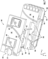
- FIG. 15 depicts a front view of the assembled multiport assembly 100 of FIG. 12 with dust plug 650 without a tether inserted into input connector port 124 and the dust plug bodies 610 of dust plug 600 inserted into respective optical connector ports 120.
- the input connector port 124 uses a different style of dust plug 650 without a tether compared with dust plug 650 having a tether.
- the dust plug tether of dust plug 650 is flexible so it is easily bendable so that it may have a portion that is attached to multiport assembly 100.
- the dust plug 600 and dust plug 650 share similar geometry of a locking feature and keying portion for cooperating with the respective connector ports 120,124 of the multiport assembly.
- Using two different styles of dust plugs allows the user to easily identify and distinguish the input connector port 124 from the connector ports 120 for making optical connections toward downstream users in the network.
- FIG. 16 depicts a first perspective view of the dust plug 600 where the locking feature 612 is visible.
- Locking feature 612 comprises a ramp portion with a ledge. The ramp portion and ledge are integrally formed in the dust plug body 610 and cooperate with a translating securing element associated with the respective connector port 124 to secure the same.
- the respective push-button 190 needs to be pressed downward to translate the locking feature and allowing the release of the dust plug when pulling on the tether.
- FIG. 17 depicts a second perspective view of dust plug 600 showing the keying portion 614.
- FIG. 17A depicts end 601 of the dust plug tether. As depicted, the end 601 has a slot 601a for positioning the end on a rib of the shell 110 for placement so it aligns with the slot 401 of mounting member 400. End 601 also having a larger flared out portion with protrusions 601b on each side for inhibiting the pullout of the dust plug tether from between the mounting member 400 and shell 110.
- Dust plugs 600 provides a flexible dust plug tether so that the dust plug body 610 may be easily positioned as desired such as installing into the connector port 120 or securing the dust plug body to a dust cap of an external plug connector to keep it out of the way, but allow the dust plug to be available for re-insertion into the connector port 120 if needed.
- the materials and geometry of the dust plug tether aid in determining the flexibility or performance of the dust plug tether.
- the dust plug body 610 comprises a first material and the dust plug tether comprises a second material.
- the dust plug tether may comprises a portion that is overmolded about a portion of the dust plug body 610 using two different materials.
- the first material for the dust plug body 610 may be harder than the second material for the dust plug tether.
- Another characteristic that may be tailored for desired performance between the first and second materials is the flexural modulus.
- the flexural modulus for the first material of the dust plug body 610 may be much larger than the flexural modulus of the second material for the dust plug tether.
- the first material may have a flexural modulus that is 100 times greater than a flexural modulus of the second material.
- the performance flexibility of the second material may also be selected by hardness in one embodiment the second material has a Shore D hardness in the range of 40-50.
- a suitable second material for the dust plug tether is a thermoplastic polyester elastomer.
- thermoplastic polyester elastomer is HYTREL ® 4556 available from Dupont Performance Polymers located in Wilmington, DE.
- the dust plug body 610 may be formed from XAREC TM EA357 which is a syndiotactic polystyrene available from Idemitsu Kosan Co., Ltd of Tokyo, Japan or Veradel ® AG320 available from Specialty Polymers of Alpharetta, GA.
- FIGS. 18 and 19 are perspective views showing details of dust plug 650 shown in the input connector port 124 in FIG. 15 .
- Dust plug 650 is similar to dust plug 600 in that it has a locking feature 612 and keying portion 614, but it may be formed from a single material without a dust plug tether. Instead, dust plug 650 comprises an enlarged end 651 on a pulling grip 651 so it may be easily removed from the input connector port 124 when its respective push-button 190 is depressed. Dust plug 650 may also comprise a groove for a O-ring 625 for sealing the dust cap 650 to the connector port like dust plug 600.
- FIGS. 20 and 21 are schematically depict other concepts that may be used with the dust plugs disclosed herein.
- dust plugs 600 or 650 may have one or more slight protruding portions 663 near the interface with the connector port of multiport assembly 100 when inserted therein so that the dust plug body is inhibited from over-insertion and making the dust plug easier to remove.
- FIG. 21 depicts dust plug 600 or 650 that further comprises a light pipe LP that is in communication with the respective optical fiber of the connector port so that the user may be able to tell if there is an optical connection or a test signal at the respective port.
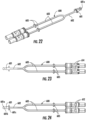
- FIGS. 22-24 depict views of another dust plug 600 having a dust plug tether similar to the dust plug shown in FIGS. 16 and 17 .
- the end 601 of the dust plug 600 has a different configuration for engaging with a faceplate 700 as shown in FIGS. 25 and 26 .
- end 601 comprises a head 601a having rearward notches 601b disposed behind the head 601a along with a disc 601c that cooperates with a respective opening 701 in faceplate 700.
- the end 601 of dust plug 600 is inserted into the faceplate 700 until the head 601a protrudes beyond respective latches 703 of the faceplate 700 to inhibit the removal of the dust plug 600 from the faceplate 700.
- FIG. 25 and 26 the end 601 of dust plug 600 is inserted into the faceplate 700 until the head 601a protrudes beyond respective latches 703 of the faceplate 700 to inhibit the removal of the dust plug 600 from the faceplate 700.
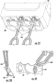
- FIG. 27 depicts the tether 600 and faceplate 700 sub-assembly of FIG. 25 attached to multiport assembly 100.
- the faceplate 700 captures a portion of the dust plug tether between the faceplate 700 and shell of the multiport assembly.
- the faceplate 700 may be attached by welding, adhesive or the like to secure it to the multiport assembly 100.
- FIGS. 28 and 29 depict the another variation of dust plug 600 having a tether where the tethers are attached to faceplate 700 in a duplex configuration (i.e., two tethers in one opening 701 of faceplate) to decrease the number of dust plug attachment points on the multiport assembly 100.
- the end 601 of each dust plug 600 has a configuration so that two ends 601 cooperate for engaging with the respective opening 701 a faceplate 700 as shown in FIGS. 28 and 29 .
- end 601 comprises a head 601a having an L-shape and a half-disc 601c that cooperates with a respective opening 701 in faceplate 700. As best shown in FIG.
- the ends 601 of dust plug 600 seat into recesses on the backside of faceplate 700, and once installed to inhibit the removal of the dust plug 600 from the faceplate 700.
- the faceplate 700 captures portions of the respective dust plug tethers between the faceplate 700 and shell of the multiport assembly, and the faceplate 700 may be attached by any suitable manner to secure it to the multiport assembly 100.
- FIGS. 30 and 31 depict a further configuration of a dust plug 600 having tether that uses a faceplate for securing an end of the tether to a multiport assembly.
- FIG. 30 depicts the dust plugs 600 having a tether where each end 601 cooperate with the shell 110 for engaging with the respective opening 701 a faceplate 700 as shown in FIG. 31 .
- end 601 comprises a head 601a having a diamond shape that is larger than the respective opening 701 in faceplate 700.
- the ends 601 of dust plugs 600 seat into a portion of shell 100 as shown in FIG. 30 for alignment and recesses on the backside of faceplate 700 inhibit the removal of the dust plug 600 from the faceplate 700.
- the faceplate 700 captures portions of the respective dust plug tethers between the faceplate 700 and shell of the multiport assembly, and the faceplate 700 may be attached by any suitable manner to secure it to the multiport assembly 100.
- FIGS. 32 and 33 depict another configuration of a dust plug 600 having tether and faceplate 700 for securing ends 601 of the tethers to a multiport assembly 100 in a duplex configuration.
- FIG. 32 depicts the dust plugs 600 having a tether where two ends 601 cooperate for engaging with the respective opening 701 a faceplate 700 as shown in FIG. 32 .
- end 601 comprises a head 601a having an rectangular shape that cooperates with a respective opening 701 in faceplate 700.
- the ends 601 of dust plugs 600 seat into recesses on the backside of faceplate 700, and once installed to inhibit the removal of the dust plug 600 from the faceplate 700.
- the faceplate 700 captures portions of the respective dust plug tethers between the faceplate 700 and shell of the multiport assembly, and the faceplate 700 may be attached by any suitable manner to secure it to the multiport assembly 100.
- FIG. 34 a lower perspective view of a multiport assembly 100 with another mounting member 500 is schematically depicted. Similar to the embodiment described above and depicted in FIGS. 11-14 , the mounting member 500 includes the forward tab 510 and the separate longitudinal member 520 spaced apart from the forward tab 510. In the embodiment depicted in FIG. 15 , the longitudinal member 520 defines the rear aperture 530, however, the rear aperture 530 is not aligned with the rear shell aperture 109. In embodiments, a fastener may be positioned through the rear aperture 530 of the mounting member 500, and another separate fastener may be positioned through the rear shell aperture 109.
- Shells have a given height H, width W and length L that define a volume for the terminal as depicted in FIG. 1 .
- shells 110 of multiport assembly 100 may define a volume of 800 cubic centimeters or less, other embodiments of shells 110 may define the volume of 400 cubic centimeters or less, other embodiments of shells 110 may define the volume of 100 cubic centimeters or less as desired.
- Some embodiments of multiport assemblies 100 comprise a port width density of at least one connector port 120,124 per 20 millimeters of width W of the multiport assembly 100. Other port width densities are possible such as 15 millimeters of width W of the terminal.
- embodiments of multiport assemblies 100 may comprise a given density per volume of the shell 110 as desired.
- Table 1 compares representative dimensions, volumes, and normalized volume ratios with respect to the prior art of the shells (i.e., the housings) for multiports having 4, 8 and 12 ports as examples of how compact the multiports of the present application are with respect to convention prior art multiports.
- Table 1 compares examples of the conventional prior art multiports with multiport assemblies like FIG. 1 having a linear array of ports with different counts of connector ports 120.
- the respective volumes of the conventional prior art multiports of FIG. 1 with the same port count are on the order often times larger than multiport assemblies with the same port count as disclosed herein.
- the multiport may define a volume of 400 cubic centimeters or less for 12-ports, or even if double the size could define a volume of 800 cubic centimeters or less for 12-ports.
- Multiports with smaller port counts such as 4-ports could be even smaller such as the shell or multiport defining a volume of 200 cubic centimeters or less for 4-ports, or even if double the size could define a volume of 200 cubic centimeters or less for 4-ports.
- Devices with sizes that are different will have different volumes form the explanatory examples in Table 1 and these other variations are within the scope of the disclosure. Consequently, it is apparent the size (e.g., volume) of multiports of the present application are much smaller than the conventional prior art multiports.
- Table 1 are for comparison purposes and other sizes and variations of multiports may use the concepts disclosed herein as desired.
- the cable input device and/or external connectors that cooperate with the multiports have locking features that are integrated into the housing of the optical connector 210.
- the locking features for holding the fiber optic connector in the respective port of the terminal are integrally formed in the housing of the connector, instead of being a distinct and separate component such as bayonets or threaded coupling nuts.
- the multiport assemblies 100 avoid the use of bulky structures such as a coupling nut or bayonet used with conventional hardened external connectors that mate to multiport assemblies 100.
- conventional external connectors for multiports have threaded connections or bayonets that require finger access for connection and disconnecting.
- the spacing between conventional connectors may be greatly reduced.
- eliminating the dedicated coupling nut from the conventional connectors also allows the footprint of the connectors to be smaller, which also aids in reducing the size of the multiports disclosed herein.
- embodiments described herein are directed to multiport assemblies including mounting members with standoff features that limit the surface area of the multiport assembly in contact with surface to which the multiport assembly is secured.
- the standoffs act to space the shell of the multiport assembly apart from the surface, which assists in limiting deformation of the shell as the shell is secured to the surface, thereby assisting in maintaining the structural integrity of the multiport assembly.
- references herein of a component of the present disclosure being "structurally configured" in a particular way, to embody a particular property, or to function in a particular manner, are structural recitations, as opposed to recitations of intended use. More specifically, the references herein to the manner in which a component is “structurally configured” denotes an existing physical condition of the component and, as such, is to be taken as a definite recitation of the structural characteristics of the component.
Landscapes
- Physics & Mathematics (AREA)
- General Physics & Mathematics (AREA)
- Optics & Photonics (AREA)
- Mechanical Coupling Of Light Guides (AREA)
- Optical Couplings Of Light Guides (AREA)
Claims (15)
- Multiportbaugruppe, Folgendes aufweisend:eine Ummantelung (110), die sich zwischen einem vorderen Ende (102) und einem im Längsrichtung dem vorderen Ende (102) entgegengesetzt positionierten hinteren Ende (104) erstreckt, wobei die Ummantelung (110) einen Hohlraum (112) und mehrere optische Verbinderanschlüsse (120), die am vorderen Ende (102) der Ummantelung (110) angeordnet sind und sich von den mehreren optischen Verbinderanschlüssen (120) zum Hohlraum (112) der Ummantelung (110) hin nach innen erstrecken, definiert;mehrere optische Adapteranordnungen (130), die innerhalb des Hohlraums (112) der Ummantelung (110) positioniert sind, wobei die mehreren optischen Adapteranordnungen (130) den mehreren optischen Verbinderanschlüssen (120) zugeordnet und strukturell dazu ausgestaltet sind, optische Verbinder optisch zu koppeln;dadurch gekennzeichnet, dass sie ferner einen Staubstopfen (600, 650) aufweist, der ein Verriegelungsmerkmal (612) und einen Schlüsselabschnitt (614) aufweist.
- Multiportbaugruppe nach Anspruch 1, wobei der Staubstopfen (600, 650) ferner einen Staubstopfenkörper (610) aufweist, der an einem Staubstopfenhalteband befestigt ist.
- Multiportbaugruppe nach Anspruch 2, ferner aufweisend eine Abdeckplatte (700) oder ein Montageelement (160, 300, 400, 500), wobei die Abdeckplatte (700) oder das Montageelement (160, 300, 400, 500) einen Abschnitt des Staubstopfenhaltebands zwischen der Abdeckplatte (700) und der Ummantelung (110) oder dem Montageelement (160, 300, 400, 500) oder der Ummantelung (110) einspannt.
- Multiportbaugruppe nach Anspruch 2, ferner aufweisend ein Montageelement (160, 300, 400, 500), das mit der Ummantelung (110) gekoppelt ist, wobei das Montageelement (160, 300, 400, 500) eine Öffnung definiert, die sich durch das Montageelement (160, 300, 400, 500) erstreckt, und mindestens einen Abstandhalter, der sich von einer unteren Fläche der Ummantelung (110) nach außen erstreckt.
- Multiportbaugruppe nach Anspruch 1, ferner aufweisend ein Montageelement (160, 300, 400, 500), das mit der Ummantelung (110) gekoppelt ist, wobei das Montageelement (160, 300, 400, 500) eine Öffnung definiert, die sich durch das Montageelement erstreckt, und mindestens einen Abstandhalter, der sich von einer unteren Fläche der Ummantelung (110) nach außen erstreckt, und wobei der Staubstopfen (600, 650) ferner einen Staubstopfenkörper (610) aufweist, der an einem Staubstopfenhalteband befestigt ist, und wobei das Montageelement (160, 300, 400, 500) einen Abschnitt des Staubstopfenhaltebands zwischen dem Montageelement (160, 300, 400, 500) und der Ummantelung (110) einspannt.
- Multiportbaugruppe nach einem der Ansprüche 2-5, wobei das Staubstopfenhalteband ferner einen Greifabschnitt (605) aufweist, der zwischen dem Staubstopfenkörper (610) und einem Ende des Staubstopfenhaltebands angeordnet ist.
- Multiportbaugruppe nach einem der Ansprüche 2-6, wobei der Staubstopfenkörper (610) ein erstes Material aufweist und das Staubstopfenhalteband ein zweites Material aufweist.
- Multiportbaugruppe nach einem der Ansprüche 2-7, wobei der Staubstopfen (600, 650) mehrere Staubstopfenkörper (610) aufweist, die an jeweiligen Schenkeln des Staubstopfenhaltebands befestigt sind.
- Multiportbaugruppe nach einem der Ansprüche 2-8, wobei das Staubstopfenhalteband einen Abschnitt aufweist, der um einen Abschnitt des Staubstopfenkörpers (610) aufgeformt ist.
- Multiportbaugruppe nach einem der Ansprüche 1-9, ferner aufweisend ein zweites Montageelement, das eine Öffnung und einen Abstandhalterabschnitt aufweist, und wobei die Ummantelung (110) eine hintere Ummantelungsöffnung (109) definiert, die einen Abschnitt des zweiten Montageelements aufnimmt.
- Multiportbaugruppe nach Anspruch 10, wobei das zweite Montageelement an der Ummantelung (110) befestigt ist und ein auskragendes Ende aufweist, das nicht an der Ummantelung (110) befestigt ist.
- Multiportbaugruppe nach einem der Ansprüche 1-11, wobei die mehreren optischen Adapteranordnungen (130) jeweiligen Tasterelementen (190) zum Verschieben eines Sicherungsteils zugeordnet sind.
- Multiportbaugruppe nach einem der Ansprüche 1-12, ferner aufweisend mindestens ein elastisches Sicherungselement (190RM) zum Vorspannen eines Abschnitts des Sicherungsteils.
- Multiportbaugruppe nach einem der Ansprüche 1-12, wobei das Sicherungsteil (190A) ein Verriegelungsmerkmal (190L) aufweist, das in einer Bohrung (190B) angeordnet ist.
- Multiportbaugruppe nach Anspruch 14, wobei das Verriegelungsmerkmal (190L) eine Rampe mit einem Vorsprung an der Rückseite aufweist.
Priority Applications (2)
| Application Number | Priority Date | Filing Date | Title |
|---|---|---|---|
| HRP20241645TT HRP20241645T1 (hr) | 2018-12-28 | 2019-12-20 | Sklopovi s više priključaka koji uključuju značajke za montažu ili čepove za prašinu |
| EP24203775.2A EP4471478A3 (de) | 2018-12-28 | 2019-12-20 | Multiport-anordnungen mit montagemerkmalen oder staubstopfen |
Applications Claiming Priority (2)
| Application Number | Priority Date | Filing Date | Title |
|---|---|---|---|
| US201862785871P | 2018-12-28 | 2018-12-28 | |
| PCT/US2019/067781 WO2020139745A1 (en) | 2018-12-28 | 2019-12-20 | Multiport assemblies including mounting features or dust plugs |
Related Child Applications (2)
| Application Number | Title | Priority Date | Filing Date |
|---|---|---|---|
| EP24203775.2A Division EP4471478A3 (de) | 2018-12-28 | 2019-12-20 | Multiport-anordnungen mit montagemerkmalen oder staubstopfen |
| EP24203775.2A Division-Into EP4471478A3 (de) | 2018-12-28 | 2019-12-20 | Multiport-anordnungen mit montagemerkmalen oder staubstopfen |
Publications (2)
| Publication Number | Publication Date |
|---|---|
| EP3903136A1 EP3903136A1 (de) | 2021-11-03 |
| EP3903136B1 true EP3903136B1 (de) | 2024-11-06 |
Family
ID=69185714
Family Applications (2)
| Application Number | Title | Priority Date | Filing Date |
|---|---|---|---|
| EP19839740.8A Active EP3903136B1 (de) | 2018-12-28 | 2019-12-20 | Multiportbaugruppen mit befestigungsmerkmalen oder staubstopfen |
| EP24203775.2A Pending EP4471478A3 (de) | 2018-12-28 | 2019-12-20 | Multiport-anordnungen mit montagemerkmalen oder staubstopfen |
Family Applications After (1)
| Application Number | Title | Priority Date | Filing Date |
|---|---|---|---|
| EP24203775.2A Pending EP4471478A3 (de) | 2018-12-28 | 2019-12-20 | Multiport-anordnungen mit montagemerkmalen oder staubstopfen |
Country Status (10)
| Country | Link |
|---|---|
| US (2) | US12044894B2 (de) |
| EP (2) | EP3903136B1 (de) |
| CA (1) | CA3125271C (de) |
| ES (1) | ES3010435T3 (de) |
| HR (1) | HRP20241645T1 (de) |
| HU (1) | HUE069765T2 (de) |
| MX (1) | MX2021007772A (de) |
| PL (1) | PL3903136T3 (de) |
| PT (1) | PT3903136T (de) |
| WO (1) | WO2020139745A1 (de) |
Families Citing this family (21)
| Publication number | Priority date | Publication date | Assignee | Title |
|---|---|---|---|---|
| US11668890B2 (en) | 2017-06-28 | 2023-06-06 | Corning Research & Development Corporation | Multiports and other devices having optical connection ports with securing features and methods of making the same |
| HUE064357T2 (hu) | 2017-06-28 | 2024-03-28 | Corning Res & Dev Corp | Kompakt száloptikai csatlakozók |
| USD941821S1 (en) * | 2017-10-03 | 2022-01-25 | Corning Research & Development Corporation | Multiport for making optical connections |
| USD941296S1 (en) * | 2017-10-03 | 2022-01-18 | Corning Research & Development Corporation | Multiport for making optical connections |
| USD1092479S1 (en) | 2018-03-29 | 2025-09-09 | Corning Research & Development Corporation | Double stack multiport for making optical connections |
| USD951954S1 (en) * | 2018-03-29 | 2022-05-17 | Corning Research & Development Corporation | Double stack multiport for making optical connections |
| MX2021006211A (es) | 2018-11-29 | 2021-08-11 | Corning Res & Dev Corp | Multipuertos y otros dispositivos que tienen puertos de conexion optica con accionadores giratorios y metodos de fabricacion de los mismos. |
| USD913246S1 (en) * | 2019-06-21 | 2021-03-16 | Corning Research & Development Corporation | Multiport terminal for making optical connections |
| MX2021014427A (es) | 2019-05-31 | 2022-03-04 | Corning Res & Dev Corp | Multipuertos y otros dispositivos que tienen puertos de conexion optica con accionadores deslizantes y metodos para elaborar los mismos. |
| EP3805827B1 (de) | 2019-10-07 | 2025-07-30 | Corning Research & Development Corporation | Faseroptische anschlüsse und faseroptische netzwerke mit kopplern mit variablem verhältnis |
| PL4045957T3 (pl) | 2019-10-18 | 2024-04-29 | Corning Research & Development Corporation | Terminale mające optyczne porty połączeniowe z elementami mocującymi zapewniającymi stałe siły utrzymania |
| USD949107S1 (en) * | 2019-12-20 | 2022-04-19 | Corning Research & Development Corporation | Dustplug for a multiport optical connection device |
| EP4172671B1 (de) | 2020-06-29 | 2026-01-21 | Corning Research & Development Corporation | Anschlüsse mit einem optischen mehrfaserverbindungsport zur verhinderung von schäden von einzelfaserverbindern |
| US11604320B2 (en) | 2020-09-30 | 2023-03-14 | Corning Research & Development Corporation | Connector assemblies for telecommunication enclosures |
| EP4237890A2 (de) | 2020-10-30 | 2023-09-06 | Corning Research & Development Corporation | Faseroptische verbinder mit einem wetterfesten kragen |
| US20220163731A1 (en) * | 2020-11-24 | 2022-05-26 | Corning Research & Development Corporation | Multiports and other devices having connection port inserts and methods of making the same |
| US11880076B2 (en) | 2020-11-30 | 2024-01-23 | Corning Research & Development Corporation | Fiber optic adapter assemblies including a conversion housing and a release housing |
| WO2022235524A1 (en) * | 2021-05-07 | 2022-11-10 | Commscope Technologies Llc | Packaging lanyard for connector converters |
| WO2023092335A1 (zh) * | 2021-11-24 | 2023-06-01 | 华为技术有限公司 | 一种连接器 |
| US20250164726A1 (en) * | 2022-02-02 | 2025-05-22 | Commscope Technologies Llc | Telecommunication enclosure with dense connector port configuration |
| CN118112725A (zh) * | 2024-03-25 | 2024-05-31 | 深圳市爱德泰科技有限公司 | 光纤连接装置 |
Family Cites Families (352)
| Publication number | Priority date | Publication date | Assignee | Title |
|---|---|---|---|---|
| US3792284A (en) | 1972-10-13 | 1974-02-12 | Gte Sylvania Inc | Electro-optic transmission link |
| US4003297A (en) | 1975-03-28 | 1977-01-18 | Du-Al Manufacturing Company | Hydraulic cylinder |
| US4077567A (en) | 1976-06-18 | 1978-03-07 | Universal Pneumatic Controls, Inc. | Pneumatic temperature reset differential pressure controller |
| FR2485754A1 (fr) | 1980-06-30 | 1981-12-31 | Perena | Connecteur de fibres optiques |
| US4413880A (en) | 1981-01-02 | 1983-11-08 | Bowmar/Ali, Inc. | Adaptable connector for a fiber optic testing device |
| WO1984002005A1 (en) | 1982-11-12 | 1984-05-24 | Univ Leland Stanford Junior | Fiber optic switch and discretely variable delay line |
| US4547937A (en) | 1983-09-06 | 1985-10-22 | Gerber Legendary Blades | Snap lock connector with push-button release |
| US4634858A (en) | 1984-10-17 | 1987-01-06 | Sperry Corporation | Variable coupler fiberoptic sensor |
| JPS61145509A (ja) | 1984-12-19 | 1986-07-03 | Fujikura Ltd | 光カプラ− |
| US4688200A (en) | 1985-09-18 | 1987-08-18 | Western Geophysical Company Of America | Optical system for detecting acoustic wave energy in a fluid medium |
| US4793683A (en) | 1986-05-08 | 1988-12-27 | American Telephone And Telegraph Company, At&T Bell Laboratories | Optical fiber connector |
| JPS6378908A (ja) | 1986-09-19 | 1988-04-09 | 三菱重工業株式会社 | 高所除雪車 |
| JPS6389421A (ja) | 1986-09-30 | 1988-04-20 | Nippon Electric Glass Co Ltd | 板ガラス成形装置 |
| US5131735A (en) | 1989-06-15 | 1992-07-21 | Corning Incorporated | Fiber optic coupler |
| JPH0827434B2 (ja) | 1989-07-31 | 1996-03-21 | タツタ電線株式会社 | 光可変結合器及びその光結合度選択方法 |
| ATE108583T1 (de) | 1989-09-25 | 1994-07-15 | Siemens Ag | Verfahren und vorrichtung zur speisung eines drehspannungsnetzes mit belastbarem null-leiter. |
| US5673346A (en) * | 1989-11-24 | 1997-09-30 | Nippon Telegraph And Telephone Corporation | Optical jack for plug-jack optical connector |
| US5007860A (en) | 1990-01-19 | 1991-04-16 | Leviton Manufacturing Co., Inc. | Modular higher density communications coupling system |
| US4994134A (en) | 1990-02-12 | 1991-02-19 | Siecor Corporation | Method of making a ferrule having enhanced concentricity |
| US5073042A (en) | 1990-06-21 | 1991-12-17 | Amp Incorporated | Coupling bushing for various types of optical fiber connectors |
| US5146519A (en) | 1990-08-28 | 1992-09-08 | Corning Incorporated | Rotary variable optical tap |
| US5067783A (en) | 1990-10-16 | 1991-11-26 | At&T Bell Laboratories | Optical fiber connector buildout system |
| US5129023A (en) | 1991-05-14 | 1992-07-07 | At&T Bell Laboratories | Optical fiber connector having enhanced provisions for interconnection and for prevention of optical and mechanical disconnection |
| US5212752A (en) | 1992-05-27 | 1993-05-18 | At&T Bell Laboratories | Optical fiber ferrule connector having enhanced provisions for tuning |
| GB2268813B (en) | 1992-07-13 | 1995-04-19 | Integrated Optical Components | Packaged optical devices |
| JPH07318758A (ja) | 1994-05-26 | 1995-12-08 | Nippon Sheet Glass Co Ltd | 光コネクタ |
| US5408570A (en) | 1994-06-30 | 1995-04-18 | Minnesota Mining And Manufacturing Company | Fiber optic housing with low part count |
| US5600747A (en) | 1994-08-12 | 1997-02-04 | The Furukawa Electric Co., Ltd. | Method of collectively connecting multiple optical connectors and aligning and positioning jig for multiple optical connectors used in the method |
| NZ303594A (en) | 1995-03-31 | 1999-01-28 | Minnesota Mining & Mfg | Optical fibre splice tray arrangement |
| US5631993A (en) | 1995-04-20 | 1997-05-20 | Preformed Line Products Company | Optical fiber splice case |
| JP2804242B2 (ja) | 1995-04-24 | 1998-09-24 | 住友電気工業株式会社 | 光ファイバケーブルの牽引端末および牽引端末における光ファイバ心線の収納方法 |
| EP0758098A1 (de) | 1995-08-09 | 1997-02-12 | Molex Incorporated | Adapteranordnung für faseroptische Verbinder |
| DE69608314T2 (de) | 1995-11-22 | 2001-01-04 | Bowthorpe Plc, Crawley | Spleissanordnungen für faseroptische kabel |
| US5647045A (en) | 1996-02-23 | 1997-07-08 | Leviton Manufacturing Co., Inc. | Multi-media connection housing |
| JPH10339826A (ja) | 1997-06-09 | 1998-12-22 | Sumitomo Electric Ind Ltd | 光コネクタ、光コネクタの使用方法および光コネクタの取り外し工具 |
| US5791918A (en) | 1997-03-25 | 1998-08-11 | Pierce; William E. | Spark plug connector |
| US5940561A (en) | 1997-04-23 | 1999-08-17 | Siecor Corporation | Adapter assembly for precise alignment of fiber optic connectors |
| US5867621A (en) | 1997-04-23 | 1999-02-02 | Siecor Corporation | Adapter and guide pin assembly for coupling of fiber optic connectors |
| US5782892A (en) | 1997-04-25 | 1998-07-21 | Medtronic, Inc. | Medical lead adaptor for external medical device |
| US5862290A (en) | 1997-05-01 | 1999-01-19 | Lucent Technologies Inc. | Optical fiber cable splice closure |
| JP3475050B2 (ja) | 1997-08-12 | 2003-12-08 | 古河電気工業株式会社 | 光コネクタクリップ |
| US5961344A (en) | 1997-08-26 | 1999-10-05 | Yazaki Corporation | Cam-actuated terminal connector |
| US6104855A (en) | 1997-09-30 | 2000-08-15 | Daewoo Telecom Ltd. | Terminal assembly for a multiple fiber optic cable |
| JPH11119064A (ja) | 1997-10-17 | 1999-04-30 | Fujitsu Ltd | 光伝送端末装置 |
| US6108482A (en) | 1998-01-14 | 2000-08-22 | Molex Incorporated | Fiber optic connector receptacle |
| JP3331406B2 (ja) | 1998-05-18 | 2002-10-07 | 日本航空電子工業株式会社 | ロック用バネ着脱治具 |
| US6350062B2 (en) | 1999-05-07 | 2002-02-26 | Corning Cable Systems Llc | Multifiber ferrule defining alignment holes having a tapered lead-in portion |
| US7422376B2 (en) | 1999-12-07 | 2008-09-09 | Molex Incorporated | Self-contained fiber optic connector module |
| US6816661B1 (en) | 2000-03-22 | 2004-11-09 | Corning Cable Systems Llc | Multifiber connector, installation tool and associated methods of validating optical fiber continuity |
| JP3857859B2 (ja) | 2000-04-04 | 2006-12-13 | 古河電気工業株式会社 | 光コネクタ用アダプタ |
| US9239441B2 (en) | 2000-05-26 | 2016-01-19 | Corning Cable Systems Llc | Fiber optic drop cables and preconnectorized assemblies having toning portions |
| US7467896B2 (en) | 2000-05-26 | 2008-12-23 | Corning Cable Systems Llc | Fiber optic drop cables and preconnectorized assemblies |
| US6375363B1 (en) | 2000-06-02 | 2002-04-23 | Cisco Technology, Inc. | Multi-part optical safety clip |
| US6466725B2 (en) | 2000-11-29 | 2002-10-15 | Corning Cable Systems Llc | Apparatus and method for splitting optical fibers |
| US6386891B1 (en) | 2000-12-28 | 2002-05-14 | Hubbell Incorporated | Multiport assembly having a floating electrical circuit board within an enclosure assembly |
| US6579013B2 (en) | 2001-03-15 | 2003-06-17 | Jds Uniphase Corporation | Optical fiber coupler and an optical fiber coupler incorporated within a transceiver module |
| US6738555B1 (en) | 2001-03-28 | 2004-05-18 | Corning Cable Systems Llc | Furcation kit |
| US6554489B2 (en) | 2001-03-28 | 2003-04-29 | Corning Cable Systems Llc | Fiber optic cable guide and method of application |
| US20030016440A1 (en) | 2001-07-17 | 2003-01-23 | Terra Worx, Inc. | Optical fiber oven |
| US6536956B2 (en) | 2001-07-26 | 2003-03-25 | Corning Cable Systems Llc | Ferrule boot for optical connectors |
| US6579014B2 (en) | 2001-09-28 | 2003-06-17 | Corning Cable Systems Llc | Fiber optic receptacle |
| US6672774B2 (en) | 2001-10-05 | 2004-01-06 | Corning Cable Systems Llc | Post-connectorization boot, connectorized fiber optic cable assembly including same, and related methods |
| JP3907991B2 (ja) | 2001-10-09 | 2007-04-18 | 株式会社フジクラ | 光コネクタレセプタクル |
| US6550979B1 (en) | 2001-10-19 | 2003-04-22 | Corning Cable Systems Llc | Floating connector subassembly and connector including same |
| US6923579B2 (en) | 2001-11-30 | 2005-08-02 | Corning Cable Systems Llc | Fiber optic component marking with fiber optic indicia |
| JP3816378B2 (ja) | 2001-12-07 | 2006-08-30 | 株式会社フジクラ | 光コネクタレセプタクルおよび光接続部品 |
| US6916120B2 (en) | 2002-01-30 | 2005-07-12 | Adc Telecommunications, Inc. | Fiber optic connector and method |
| US6629782B2 (en) | 2002-02-04 | 2003-10-07 | Adc Telecommunications, Inc. | Tuned fiber optic connector and method |
| US6688776B2 (en) | 2002-04-12 | 2004-02-10 | 3M Innovative Properties Company | Interconnect device |
| JP3808795B2 (ja) | 2002-04-16 | 2006-08-16 | 株式会社精工技研 | 光機能部品 |
| US6678442B2 (en) | 2002-04-24 | 2004-01-13 | Pangrac And Associates Development, Inc. | Fiber optic connector for a segmented FTTH optical network |
| US6771861B2 (en) | 2002-05-07 | 2004-08-03 | Corning Cable Systems Llc | High performance, flexible optical fiber furcation |
| US6702475B1 (en) | 2002-05-07 | 2004-03-09 | Cisco Technology, Inc. | Release system for optical connectors |
| DE60224877T2 (de) | 2002-08-16 | 2008-05-15 | Agilent Technologies Inc., Santa Clara | Optische Verbindungsvorrichtung zum Koppeln von Verbindern an ein Gerät mit mehreren Anschlüssen |
| JP4266319B2 (ja) | 2002-09-06 | 2009-05-20 | 株式会社精工技研 | 光コネクタプラグ及び光コネクタ |
| US6644862B1 (en) | 2002-09-25 | 2003-11-11 | Agilent Technolgies, Inc. | Optical mount |
| US20040120656A1 (en) | 2002-12-18 | 2004-06-24 | Vladimir Banas | Angled spring push for optical ribbon cable |
| US6764221B1 (en) | 2002-12-30 | 2004-07-20 | Corning Calde Systems Llc | Flexible, multi-fiber fiber optic jumper |
| CA2454438A1 (en) | 2003-02-07 | 2004-08-07 | Hypertronics Corporation | Connecting device |
| JP4131687B2 (ja) | 2003-07-10 | 2008-08-13 | 日本電信電話株式会社 | 光コネクタ及び光コネクタボックス |
| FI20031104A0 (fi) | 2003-07-25 | 2003-07-25 | Nokia Corp | Yksikuituinen suojaus tietoliikenneverkoissa |
| US7366416B2 (en) | 2003-08-11 | 2008-04-29 | General Instrument Corporation | Hub for a passive optical network hub |
| JP4030940B2 (ja) | 2003-08-29 | 2008-01-09 | 日本電信電話株式会社 | 光コネクタ及び光コネクタボックス |
| US6962445B2 (en) | 2003-09-08 | 2005-11-08 | Adc Telecommunications, Inc. | Ruggedized fiber optic connection |
| US6856748B1 (en) | 2003-09-30 | 2005-02-15 | Corning Cable Systems Llc | Interconnection enclosure having a connector port and preterminated optical connector |
| US7216512B2 (en) | 2003-10-31 | 2007-05-15 | Corning Cable Systems, Llc | Method of making an optical fiber by laser cleaving |
| US6983095B2 (en) | 2003-11-17 | 2006-01-03 | Fiber Optic Network Solutions Corporation | Systems and methods for managing optical fibers and components within an enclosure in an optical communications network |
| US7709733B1 (en) | 2003-12-12 | 2010-05-04 | Gary Dean Plankell | Recessed signal-receiver mounting system for a building structure and associated methods |
| US7120347B2 (en) | 2004-01-27 | 2006-10-10 | Corning Cable Systems Llc | Multi-port optical connection terminal |
| US7013074B2 (en) | 2004-02-06 | 2006-03-14 | Corning Cable Systems Llc | Optical connection closure having at least one connector port |
| US7292763B2 (en) | 2004-03-08 | 2007-11-06 | Adc Telecommunications, Inc. | Fiber access terminal |
| US7204644B2 (en) | 2004-03-24 | 2007-04-17 | Corning Cable Systems Llc | Field installable optical fiber connector |
| JP2005301151A (ja) | 2004-04-15 | 2005-10-27 | Canare Electric Co Ltd | 光コンタクトユニット及び光プラグ |
| JP2005316475A (ja) | 2004-04-29 | 2005-11-10 | Sumitomo Electric Ind Ltd | 光トランシーバ |
| US7130519B2 (en) | 2004-05-11 | 2006-10-31 | Preformed Line Products Company | Convertible fiber closure platform |
| US7146090B2 (en) | 2004-06-17 | 2006-12-05 | Corning Cable Systems Llc | Fiber optic cable and plug assembly |
| JP4108651B2 (ja) | 2004-07-07 | 2008-06-25 | 株式会社フジクラ | 光配線ユニット |
| US20060045428A1 (en) | 2004-08-24 | 2006-03-02 | Thomas Theuerkorn | Fiber optic receptacle and plug assemblies |
| US7489849B2 (en) | 2004-11-03 | 2009-02-10 | Adc Telecommunications, Inc. | Fiber drop terminal |
| US7680388B2 (en) | 2004-11-03 | 2010-03-16 | Adc Telecommunications, Inc. | Methods for configuring and testing fiber drop terminals |
| US7266274B2 (en) | 2004-11-03 | 2007-09-04 | Corning Cable Systems Llc | Pre-connectorized fiber optic distribution cable having overmolded access location |
| US7346256B2 (en) | 2004-11-04 | 2008-03-18 | Panduit Corp. | Re-terminable LC connector assembly and cam termination tool |
| US7033191B1 (en) | 2004-12-02 | 2006-04-25 | Optical Communication Products, Inc. | Pluggable optical transceiver with sliding actuator |
| US7277614B2 (en) * | 2004-12-03 | 2007-10-02 | Corning Cable Systems Llc | Tether assembly having individual connector ports |
| WO2006069093A1 (en) | 2004-12-20 | 2006-06-29 | Molex Incorporated | Optical fiber connector assembly |
| KR20070089242A (ko) | 2004-12-20 | 2007-08-30 | 몰렉스 인코포레이티드 | 인덱싱된 광섬유 커넥터 |
| US7428366B2 (en) | 2004-12-22 | 2008-09-23 | Tyco Electronics Corporation | Optical fiber termination apparatus with connector adaptor and method for using the same |
| US7469091B2 (en) | 2004-12-22 | 2008-12-23 | Tyco Electronics Corporation | Optical fiber termination apparatus and methods for using the same |
| US7302152B2 (en) | 2004-12-30 | 2007-11-27 | Corning Cable Systems Llc | Overmolded multi-port optical connection terminal having means for accommodating excess fiber length |
| US7261472B2 (en) | 2005-01-12 | 2007-08-28 | Illum Technologies, Inc. | Ultra-small, form factor single fiber optical interconnect system, with push-push type insertion/withdrawal mechanism and shuttered modular connector and shuttered adapter and method for using same |
| US7785019B2 (en) | 2005-03-10 | 2010-08-31 | Corning Cable Systems Llc | Multi-fiber fiber optic receptacle and plug assembly |
| US7264402B2 (en) | 2005-03-10 | 2007-09-04 | Corning Cable Systems Llc | Multi-fiber optic receptacle and plug assembly |
| US7349605B2 (en) | 2005-04-19 | 2008-03-25 | Adc Telecommunications, Inc. | Fiber breakout with radio frequency identification device |
| US7266265B2 (en) | 2005-05-02 | 2007-09-04 | Pangrac & Associates Development, Inc. | Low-loss shared FTTH distribution network |
| JP4762982B2 (ja) | 2005-05-19 | 2011-08-31 | 株式会社フジクラ | コネクタホルダ、コネクタホルダ付き光電気変換器、コネクタホルダの組立方法、ホルダ基部 |
| US7260301B2 (en) | 2005-05-25 | 2007-08-21 | Adc Telecommunications, Inc. | Outside plant fiber distribution enclosure with radial arrangement |
| US7150567B1 (en) | 2005-05-27 | 2006-12-19 | Corning Cable Systems Llc | Fiber optic connector having keyed ferrule holder |
| US7444056B2 (en) | 2005-05-31 | 2008-10-28 | Tyco Electronics Corporation | Optical network architecture and terminals for use in such networks |
| JP2006337637A (ja) | 2005-06-01 | 2006-12-14 | Furukawa Electric Co Ltd:The | 光素子結合ロックキー及び光送受信機 |
| US20070031100A1 (en) | 2005-08-04 | 2007-02-08 | Garcia Cesar G | Optical fiber distribution cabinet |
| KR100735293B1 (ko) | 2005-08-12 | 2007-07-03 | 삼성전자주식회사 | 파장분할다중 방식의 광원 및 이를 이용한 파장분할다중방식의 수동형 광가입자망 |
| US7330629B2 (en) | 2005-08-31 | 2008-02-12 | Corning Cable Systems Llc | Fiber optic universal bracket apparatus and methods |
| FR2890508A1 (fr) | 2005-09-06 | 2007-03-09 | France Telecom | Dispositif de conversion d'energie et son application a la telealimentation et/ou telecommande de composants optiques actifs deportes dans un reseau de telecommunication optique |
| JP4818666B2 (ja) | 2005-09-09 | 2011-11-16 | 株式会社フジクラ | 光コネクタレセプタクル、光コネクタレセプタクル付き基板 |
| JP4205093B2 (ja) | 2005-10-31 | 2009-01-07 | 株式会社フジクラ | 光コネクタレセプタクル及び光コネクタ |
| EP1949157B1 (de) | 2005-11-14 | 2019-02-27 | Corning Optical Communications LLC | Nebenkabel mit faseroptischem verbinder und herstellungsverfahren dafür |
| US7753596B2 (en) | 2005-11-22 | 2010-07-13 | Corning Cable Systems Llc | Fiber optic closure methods and apparatus |
| US7477824B2 (en) | 2006-04-05 | 2009-01-13 | Adc Telecommunications, Inc. | Universal bracket for mounting a drop terminal |
| US7391952B1 (en) | 2006-08-31 | 2008-06-24 | Corning Cable Systems Llc | Pre-connectorized fiber optic cable network interconnection apparatus |
| CA2660175C (en) | 2006-09-01 | 2015-05-12 | Zymogenetics, Inc. | Variable region sequences of il-31 monoclonal antibodies and methods of use |
| DK2074455T3 (da) | 2006-09-05 | 2012-05-29 | Prysmian Cables & Systems Ltd | System til indstikning af et fiberoptisk kabel i en fiberoptisk stikdåse og kabeladaptor dertil |
| CN101195453A (zh) | 2006-12-05 | 2008-06-11 | 3M创新有限公司 | 线缆松弛处理设备 |
| JP4262740B2 (ja) | 2006-12-12 | 2009-05-13 | 日本航空電子工業株式会社 | 光コネクタ |
| US20080175548A1 (en) | 2007-01-23 | 2008-07-24 | Dennis Michael Knecht | Preconnectorized fiber optic cable assembly |
| US7614797B2 (en) | 2007-01-24 | 2009-11-10 | Adc Telecommunications, Inc. | Fiber optic connector mechanical interface converter |
| US7591595B2 (en) | 2007-01-24 | 2009-09-22 | Adc Telelcommunications, Inc. | Hardened fiber optic adapter |
| JP4728976B2 (ja) | 2007-02-05 | 2011-07-20 | 山一電機株式会社 | 光コネクタの解除可能なロック機構 |
| US7499622B2 (en) | 2007-02-28 | 2009-03-03 | Corning Cable Systems Llc | Fiber optic drop terminals for multiple dwelling units |
| US8254741B2 (en) | 2007-03-12 | 2012-08-28 | Sumitomo Electric Industries, Ltd. | Optical cable connecting closure and optical interconnection system |
| US7738759B2 (en) | 2007-03-16 | 2010-06-15 | 3M Innovative Properties Company | Optical fiber cable inlet device |
| US7512304B2 (en) | 2007-03-23 | 2009-03-31 | Adc Telecommunications, Inc. | Drop terminal with anchor block for retaining a stub cable |
| US7485804B2 (en) | 2007-04-27 | 2009-02-03 | Thomas & Betts International, Inc. | Multi-media recess data low voltage box with slide-away hidden cover |
| US7806599B2 (en) | 2007-05-04 | 2010-10-05 | Illum Technologies, Inc. | Super miniature, single fiber optical interconnect system with parallel slider push-push type insertion/withdrawal mechanism and method for using same |
| WO2008137897A1 (en) | 2007-05-06 | 2008-11-13 | Adc Telecommunications, Inc. | Mechanical interface converter for making non-ruggedized fiber optic connectors compatible with a ruggedized fiber optic adapter |
| US7734138B2 (en) | 2007-05-30 | 2010-06-08 | Corning Cable Systems Llc | Fiber optic connector holders |
| US20080298743A1 (en) | 2007-05-31 | 2008-12-04 | Konstantinos Saravanos | Microsplitter module for optical connectivity |
| US7628545B2 (en) | 2007-06-18 | 2009-12-08 | Corning Cable Systems Llc | Fiber optic plug assembly with boot and crimp band |
| US8408811B2 (en) | 2007-07-16 | 2013-04-02 | Corning Cable Systems Llc | Fusion-splice fiber optic connectors and related tools |
| US20090041412A1 (en) | 2007-08-07 | 2009-02-12 | Jeffrey Dean Danley | Laser erosion processes for fiber optic ferrules |
| US7740409B2 (en) | 2007-09-19 | 2010-06-22 | Corning Cable Systems Llc | Multi-port optical connection terminal |
| US7785017B2 (en) | 2007-09-27 | 2010-08-31 | Corning Cable Systems Llc | Strain-relief assemblies and methods for a field-installable fiber optic connector |
| US7628548B2 (en) | 2007-10-01 | 2009-12-08 | Corning Cable Systems Llc | Index-matching gel for nanostructure optical fibers and mechanical splice assembly and connector using same |
| US7742670B2 (en) | 2007-10-01 | 2010-06-22 | Corning Cable Systems Llc | Index-matching gel for nanostructure optical fibers and mechanical splice assembly and connector using same |
| MX2010003804A (es) | 2007-10-09 | 2010-04-21 | Adc Telecommunications Inc | Mini terminal de conexion. |
| US7903923B2 (en) | 2007-10-09 | 2011-03-08 | Adc Telecommunications, Inc. | Drop terminal releasable engagement mechanism |
| US7744286B2 (en) | 2007-12-11 | 2010-06-29 | Adc Telecommunications, Inc. | Hardened fiber optic connection system with multiple configurations |
| US7628640B2 (en) | 2007-12-14 | 2009-12-08 | Actuant Corporation | Electrical connector for connection to multiple conductors |
| US8238709B2 (en) | 2007-12-18 | 2012-08-07 | Adc Telecommunications, Inc. | Multi-configuration mounting system for fiber distribution hub |
| US8111966B2 (en) | 2008-01-09 | 2012-02-07 | Adc Telecommunications, Inc. | Wall box adapted to be mounted at a mid-span access location of a telecommunications cable |
| KR101212294B1 (ko) | 2008-01-21 | 2012-12-12 | 삼성전자주식회사 | 화상형성장치 |
| KR100850925B1 (ko) | 2008-03-14 | 2008-08-07 | 장종호 | 광섬유 일체형 광어탭터 |
| US7542645B1 (en) | 2008-03-20 | 2009-06-02 | Corning Cable Systems Llc | Airline optical fiber with reduced multipath interference and methods of forming same |
| US7889961B2 (en) | 2008-03-27 | 2011-02-15 | Corning Cable Systems Llc | Compact, high-density adapter module, housing assembly and frame assembly for optical fiber telecommunications |
| JP2009265208A (ja) | 2008-04-23 | 2009-11-12 | Sanwa Denki Kogyo Co Ltd | 多連式光アダプタ |
| FR2930997B1 (fr) | 2008-05-06 | 2010-08-13 | Draka Comteq France Sa | Fibre optique monomode |
| US7726998B2 (en) | 2008-07-17 | 2010-06-01 | Thomas & Betts International, Inc. | Locking pin |
| US7708476B2 (en) | 2008-07-18 | 2010-05-04 | Corning Cable Systems Llc | Index-matching gel for nano-engineered optical fibers and mechanical splice assemblies and connectors using same |
| ATE534927T1 (de) * | 2008-08-14 | 2011-12-15 | Ccs Technology Inc | Vorrichtung für den empfang einer zu einem glasfaserkabel zugeordneten unteranordnung und zur befestigung derselben an einer einrichtung |
| US8301004B2 (en) | 2008-08-29 | 2012-10-30 | Corning Cable Systems Llc | Fiber optic cable assemblies employing a furcation body having anti-rotation feature |
| US7903925B2 (en) | 2008-08-29 | 2011-03-08 | Corning Cable Systems Llc | Fiber optic furcation assembly having feature(s) for cable management |
| CN102165352A (zh) | 2008-09-23 | 2011-08-24 | 3M创新有限公司 | 带有可取出的理线器的光纤分配封装件 |
| US20100080517A1 (en) | 2008-09-29 | 2010-04-01 | Cline Timothy S | Fiber optic connector assembly employing fiber movement support and method of assembly |
| US8573855B2 (en) | 2008-10-06 | 2013-11-05 | Adc Telecommunications, Inc. | Fanout cable assembly and method |
| US9207421B2 (en) | 2008-10-14 | 2015-12-08 | Corning Cable Systems Llc | Fiber optic network architecture having optical connection terminals in series arrangement |
| JP2010152084A (ja) | 2008-12-25 | 2010-07-08 | Sanwa Denki Kogyo Co Ltd | 光ファイバコネクタ |
| US8494329B2 (en) | 2009-01-15 | 2013-07-23 | Adc Telecommunications, Inc. | Fiber optic module and chassis |
| US9711868B2 (en) | 2009-01-30 | 2017-07-18 | Karl Frederick Scheucher | In-building-communication apparatus and method |
| EP2239609B1 (de) | 2009-02-10 | 2016-11-02 | Tyco Electronics Raychem BVBA | Gehäuse für Glasfaserkabelanordnung |
| US7621675B1 (en) | 2009-02-13 | 2009-11-24 | Ofs Fitel, Llc | Single-piece cable retention housing for hardened outside plant connector |
| US8152385B2 (en) | 2009-02-27 | 2012-04-10 | Corning Cable Systems Llc | Duplex fiber optic assemblies suitable for polarity reversal and methods therefor |
| EP2237091A1 (de) | 2009-03-31 | 2010-10-06 | Corning Cable Systems LLC | Lösbar montierbares LWL-Leitungsendgerät |
| US20100266245A1 (en) | 2009-04-16 | 2010-10-21 | Hon Hai Precision Ind. Co., Ltd. | Fiber termination for fiber optic connection system |
| US20100303426A1 (en) | 2009-05-29 | 2010-12-02 | Baker Hughes Incorporated | Downhole optical fiber spice housing |
| US8025445B2 (en) | 2009-05-29 | 2011-09-27 | Baker Hughes Incorporated | Method of deployment for real time casing imaging |
| AU2010263057A1 (en) | 2009-06-19 | 2012-02-02 | Corning Cable Systems Llc | High density and bandwidth fiber optic apparatuses and related equipment and methods |
| JP5537852B2 (ja) | 2009-07-10 | 2014-07-02 | 株式会社フジクラ | 光コネクタとコネクタ嵌合ハウジングの構造 |
| JP2011033698A (ja) | 2009-07-30 | 2011-02-17 | Sumitomo Electric Ind Ltd | 光データリンク |
| US8864390B2 (en) | 2009-08-21 | 2014-10-21 | Molex Incorporated | Optical fiber connector |
| CN102667564B (zh) | 2009-10-09 | 2016-06-08 | 康宁公司 | 集成硅光激性主动光学电缆组件、子组合及组合 |
| CN102576127A (zh) | 2009-10-15 | 2012-07-11 | 康宁股份有限公司 | 用于大芯径光纤的光纤连接器和结构以及所述光纤连接器和结构的制作方法 |
| US20110091166A1 (en) | 2009-10-15 | 2011-04-21 | Seldon David Benjamin | Fiber Optic Connectors and Structures for Large Core Optical Fibers and Methods for Making the Same |
| US8934771B2 (en) | 2009-10-16 | 2015-01-13 | Xieon Networks S.A.R.L. | Optical network and method for processing data in an optical network |
| WO2011049697A1 (en) | 2009-10-21 | 2011-04-28 | Corning Cable Systems Llc | Adapter plate for securing an adapter to a surface |
| US8164050B2 (en) | 2009-11-06 | 2012-04-24 | Precision Energy Services, Inc. | Multi-channel source assembly for downhole spectroscopy |
| EP2333597B1 (de) | 2009-11-30 | 2016-09-21 | Corning Optical Communications LLC | Glasfasermodulanordnung und entsprechende Verfahren |
| US20110129185A1 (en) | 2009-11-30 | 2011-06-02 | Lewallen C Paul | Articulated Strain Relief Boot on a Fiber Optic Module and Associated Methods |
| EP2355283A1 (de) | 2010-01-29 | 2011-08-10 | Tyco Electronics Raychem BVBA | Kabelabdichtungsvorrichtung, Kabelabschluss und Befestigungsvorrichtung |
| US7901147B1 (en) | 2010-02-26 | 2011-03-08 | Corning Cable Systems Llc | Splice protector installation tool and method of use |
| CN201704194U (zh) | 2010-04-16 | 2011-01-12 | 信义光伏产业(安徽)控股有限公司 | 一种玻璃压延装置 |
| US8301003B2 (en) | 2010-05-14 | 2012-10-30 | Corning Cable Systems Llc | Cable network interconnection system with connector package and cable package |
| JP4995305B2 (ja) | 2010-06-04 | 2012-08-08 | サンコール株式会社 | 2芯型光コネクタユニット |
| ES2575887T3 (es) | 2010-06-15 | 2016-07-01 | Commscope Technologies Llc | Sistemas de envoltura de cables, enchufes y métodos para usarlos |
| JP5138005B2 (ja) | 2010-08-03 | 2013-02-06 | 株式会社精工技研 | 光通信用アダプタ |
| US8472773B2 (en) | 2010-08-06 | 2013-06-25 | Corning Cable Systems Llc | Fiber optic connector holder |
| US8221006B2 (en) | 2010-08-23 | 2012-07-17 | Corning Cable Systems Llc | Fiber optic cable assemblies with mechanically interlocking crimp bands and methods of making the assemblies |
| US8267596B2 (en) | 2010-08-23 | 2012-09-18 | Corning Cable Systems Llc | Fiber optic cable assemblies with fiber access apertures and methods of assembly |
| US8998502B2 (en) | 2010-09-03 | 2015-04-07 | Corning Incorporated | Fiber optic connectors and ferrules and methods for using the same |
| WO2012037727A1 (zh) | 2010-09-21 | 2012-03-29 | 深圳日海通讯技术股份有限公司 | 一种光纤连接器及其装配方法 |
| US9009414B2 (en) | 2010-09-21 | 2015-04-14 | Texas Instruments Incorporated | Prefetch address hit prediction to reduce memory access latency |
| AU2011308870B2 (en) | 2010-10-01 | 2015-09-24 | Corning Cable Systems Llc | Transformable ferrule assemblies and fiber optic connectors |
| US9279951B2 (en) | 2010-10-27 | 2016-03-08 | Corning Cable Systems Llc | Fiber optic module for limited space applications having a partially sealed module sub-assembly |
| US8755663B2 (en) | 2010-10-28 | 2014-06-17 | Corning Cable Systems Llc | Impact resistant fiber optic enclosures and related methods |
| US8662760B2 (en) | 2010-10-29 | 2014-03-04 | Corning Cable Systems Llc | Fiber optic connector employing optical fiber guide member |
| JP5707905B2 (ja) | 2010-12-03 | 2015-04-30 | 住友電気工業株式会社 | 光モジュール及び光システム |
| DE102011011523B4 (de) | 2011-02-17 | 2013-05-29 | Tyco Electronics Services Gmbh | Faseroptische Verbindungsanordnung und Adapterhülse |
| US8556522B2 (en) | 2011-05-27 | 2013-10-15 | Corning Cable Systems Llc | Connectors with components having a label and related cable assemblies |
| CA2877896C (en) | 2011-06-24 | 2020-07-21 | Adc Telecommunications, Inc. | Fiber termination enclosure with modular plate assemblies |
| WO2013003195A1 (en) | 2011-06-30 | 2013-01-03 | Corning Cable Systems Llc | Multi-port optical connection terminal assemblies supporting optical signal splitting, and related terminals and methods |
| US9405068B2 (en) | 2011-07-01 | 2016-08-02 | Us Conec, Ltd. | Strain relieved adapter for a jacketed cable and boot |
| US20140161397A1 (en) | 2011-07-20 | 2014-06-12 | Panduit Corp. | Fiber optic plug pack assembly |
| US8540435B2 (en) | 2011-07-22 | 2013-09-24 | Corning Cable Systems Llc | Ferrule retainers having access window(s) for accessing and/or referencing a fiber optic ferrule, and related fiber optic connector assemblies, connectors, and referencing methods |
| US8622634B2 (en) | 2011-07-29 | 2014-01-07 | Corning Cable Systems Llc | Optical fiber assemblies and methods of fabricating optical fiber assemblies |
| JP5538328B2 (ja) | 2011-08-15 | 2014-07-02 | 株式会社フジクラ | 光コネクタ保護キャップ、コネクタキャップ付き光ファイバケーブル、キャップ抜き具 |
| US9417418B2 (en) | 2011-09-12 | 2016-08-16 | Commscope Technologies Llc | Flexible lensed optical interconnect device for signal distribution |
| US8770861B2 (en) | 2011-09-27 | 2014-07-08 | Tyco Electronics Corporation | Outside plant termination enclosure |
| TWM423387U (en) | 2011-09-30 | 2012-02-21 | Chun Nien Plastic Led | Safety socket |
| RU2611105C2 (ru) | 2011-10-07 | 2017-02-21 | Адс Телекоммьюникейшнз, Инк. | Волоконно-оптическая кассета, система и способ |
| US8876404B2 (en) | 2011-10-12 | 2014-11-04 | Tyco Electronics Corporation | Receptacle connector having internal latching mechanism |
| US20130108220A1 (en) | 2011-10-31 | 2013-05-02 | Marco Antonio Gonzalez Garcia | Systems and methods for providing a ferrule boot |
| EP2773993A1 (de) | 2011-10-31 | 2014-09-10 | Corning Cable Systems LLC | Zugentlastung für pigtail-modul mit wärmeschrumpfelementen |
| US8758046B2 (en) | 2011-11-08 | 2014-06-24 | Ortronics, Inc. | Patch cord assemblies, methods and systems |
| WO2012163052A1 (zh) | 2011-11-15 | 2012-12-06 | 华为技术有限公司 | 无源光网络的通道均衡方法和装置 |
| US9977194B2 (en) | 2011-11-15 | 2018-05-22 | Molex, Llc | Wide temperature range optical fiber connector with thermal expansion compensation |
| US9304262B2 (en) | 2011-11-23 | 2016-04-05 | Commscope Technologies Llc | Multi-fiber optic connector |
| US8534928B2 (en) | 2011-11-28 | 2013-09-17 | Corning Cable Systems Llc | Optical fiber assemblies, optical fiber organizers and methods of fabricating optical fiber assemblies |
| WO2013083729A2 (en) | 2011-12-06 | 2013-06-13 | Mubea Carbo Tech Gmbh | Wheel made out of fiber reinforced material and procedure to make an according wheel |
| US8727638B2 (en) | 2011-12-21 | 2014-05-20 | Alliance Fiber Optic Products Co., Ltd. | Fiber channel-inter changeable fiber optic connector |
| KR101980128B1 (ko) | 2011-12-30 | 2019-05-21 | 한국전자통신연구원 | 하이브리드 수동형 광가입자망 시스템 |
| KR101317149B1 (ko) | 2012-01-06 | 2013-10-10 | 주식회사 에이제이월드 | 광케이블 단자함 |
| EP2802912B1 (de) | 2012-01-13 | 2017-09-06 | 3M Innovative Properties Company | Steckverbinder für die telekommunikationsgehäuse |
| US8678668B2 (en) | 2012-01-30 | 2014-03-25 | Corning Cable Systems Llc | Overmolded ferrule boot and methods for making the same |
| JP5827577B2 (ja) | 2012-01-31 | 2015-12-02 | タイコエレクトロニクスジャパン合同会社 | 光ファイバコネクタ |
| US10310208B2 (en) | 2012-02-13 | 2019-06-04 | Cable Corning Systems LLC | Fiber optic cable sub-assemblies and methods of making |
| KR20140124821A (ko) | 2012-02-21 | 2014-10-27 | 코닝 옵티컬 커뮤니케이션스 엘엘씨 | 능동형 광 케이블 (aoc) 어셈블리에서의 열 관리를 위한 구조 및 방법 |
| US8814442B2 (en) | 2012-03-07 | 2014-08-26 | Verizon Patent And Licensing Inc. | Hardened multiport optical connector assembly |
| WO2013142073A2 (en) | 2012-03-20 | 2013-09-26 | Corning Cable Systems Llc | Simplified fiber optic connectors having lenses and method for making the same |
| WO2013177234A1 (en) | 2012-05-21 | 2013-11-28 | Advanced Fiber Products, LLC | Secure sc optical fiber connector and removal tools |
| WO2013177016A1 (en) | 2012-05-22 | 2013-11-28 | Adc Telecommunications, Inc. | Ruggedized fiber optic connector |
| US9075205B2 (en) | 2012-07-11 | 2015-07-07 | Tyco Electronics Corporation | Connectors and adapters with auto-latching features |
| US9435969B2 (en) | 2012-07-11 | 2016-09-06 | Commscope Connectivity Uk Limited | Indicating communications components via illumination |
| US9158074B2 (en) | 2012-08-31 | 2015-10-13 | Adc Telecommunications, Inc. | Pivoting fiber optic cable connection device |
| US9696500B2 (en) | 2012-08-31 | 2017-07-04 | Corning Optical Communications LLC | Female hardened optical connectors for use with hybrid receptacle |
| US8998506B2 (en) | 2012-09-14 | 2015-04-07 | 3M Innovative Properties Company | Field terminable ST format optical fiber connector |
| RU2654358C2 (ru) | 2012-09-28 | 2018-05-17 | Тайко Электроникс Юк Лтд. | Волоконно-оптическая кассета |
| CN103713362B (zh) | 2012-09-28 | 2016-06-15 | 泰科电子(上海)有限公司 | 光纤连接器组件 |
| EP2717081B1 (de) | 2012-10-02 | 2020-11-18 | Corning Research & Development Corporation | Glasfaserverteilerhülse |
| JP2014085474A (ja) | 2012-10-23 | 2014-05-12 | Hitachi Metals Ltd | 光通信装置および光コネクタ |
| JP5518979B2 (ja) | 2012-11-09 | 2014-06-11 | 株式会社フジクラ | 光コネクタレセプタクル、レセプタクルハウジング、光コネクタアダプタ、アダプタハウジング |
| US9297976B2 (en) | 2012-11-14 | 2016-03-29 | Clearfield, Inc. | Optical fiber connector |
| JP2014134746A (ja) | 2013-01-11 | 2014-07-24 | Furukawa Electric Co Ltd:The | コネクタの接続構造、コネクタ、及びトランシーバ |
| US9322998B2 (en) | 2013-01-15 | 2016-04-26 | Corning Cable Systems Llc | Fiber optic connector |
| US9423570B2 (en) | 2013-02-05 | 2016-08-23 | Commscope Technologies Llc | Optical assemblies with managed connectivity |
| US20150268434A1 (en) | 2013-02-06 | 2015-09-24 | Corning Optical Communications LLC | Fiber optic multiport |
| JP5983456B2 (ja) | 2013-02-15 | 2016-08-31 | 日立金属株式会社 | フェルール固定部材 |
| JP5433802B1 (ja) | 2013-02-25 | 2014-03-05 | 日本航空電子工業株式会社 | 光コネクタ |
| US9513444B2 (en) | 2013-02-26 | 2016-12-06 | Corning Optical Communications LLC | Female hardened optical connectors for use with male plug connectors |
| US20140241689A1 (en) | 2013-02-28 | 2014-08-28 | Corning Cable Systems Llc | Ganged fiber optic connector adapter modules and assemblies having reinforcement members and staggered fiber optic connector adapter ports |
| US9482819B2 (en) | 2013-03-04 | 2016-11-01 | Alliance Fiber Optic Products, Inc. | WDM Mux/DeMux on cable and methods of making the same |
| WO2014151259A1 (en) | 2013-03-15 | 2014-09-25 | Ortronics, Inc. | Cable assemblies, methods and systems |
| CN104064903A (zh) | 2013-03-18 | 2014-09-24 | 泰科电子(上海)有限公司 | 连接器锁定装置 |
| JP6138533B2 (ja) | 2013-03-18 | 2017-05-31 | 株式会社 オプトクエスト | マルチコアファイバ用光接続器 |
| ES1148183Y (es) | 2013-04-07 | 2016-03-18 | Tyco Electronics Shanghai Co Ltd | Conjunto de conexión de fibra óptica |
| JP6044446B2 (ja) | 2013-05-01 | 2016-12-14 | 日立金属株式会社 | フェルール固定部材及びフェルール保持構造 |
| US9429732B2 (en) | 2013-05-03 | 2016-08-30 | Corning Cable Systems Llc | Fiber optic cable crimp assemblies employing integrally connected cable strain relief boots, and related fiber optic connectors, cables, and methods |
| CN203224645U (zh) | 2013-05-10 | 2013-10-02 | 深圳市天阳谷科技发展有限公司 | 保偏耦合器 |
| CN105378531A (zh) | 2013-05-21 | 2016-03-02 | 康宁光电通信有限责任公司 | 可倾斜的成组光纤适配器组件 |
| EP3004954A4 (de) | 2013-06-07 | 2017-05-10 | CommScope Technologies LLC | Telekommunikationsverbindungsvorrichtung |
| WO2014195748A1 (en) | 2013-06-07 | 2014-12-11 | FCI Asia Pte. Ltd. | Connector assembly |
| GB2515748B (en) | 2013-07-01 | 2018-09-12 | Fibrefab Ltd | Fibre optic adaptor and method for optically connecting fibre optic cable assemblies together |
| US9046660B2 (en) | 2013-07-03 | 2015-06-02 | Nexans | Fiber optic connector |
| CN203396982U (zh) | 2013-07-12 | 2014-01-15 | 东莞市联思电子有限公司 | 光纤连接器 |
| WO2015047508A1 (en) | 2013-07-16 | 2015-04-02 | 3M Innovative Properties Company | Connector for telecommunication enclosures |
| CA2917189A1 (en) * | 2013-07-16 | 2015-01-22 | 3M Innovative Properties Company | Telecommunication enclosure for external connection |
| US9618704B2 (en) | 2013-07-31 | 2017-04-11 | Corning Optical Communications LLC | Fiber optic connector sub-assemblies having a front-loading locking ferrule holder and related fiber optic components, devices and methods |
| WO2015017766A1 (en) | 2013-08-02 | 2015-02-05 | Adc Telecommunications, Inc. | Taper strain relief boot for ferrule flex connectors |
| WO2015025060A1 (en) | 2013-08-23 | 2015-02-26 | Tyco Electronics Raychem Bvba | Multi-service terminal and components therefore |
| ES3055341T3 (en) | 2013-08-24 | 2026-02-11 | CommScope Connectivity Belgium BVBA | Ruggedized fiber optic connectors and connection systems |
| WO2015088887A1 (en) | 2013-12-11 | 2015-06-18 | Corning Optical Communications LLC | Boot loader for active cable assemblies |
| US9207410B2 (en) | 2013-12-23 | 2015-12-08 | Alliance Fiber Optic Products, Inc. | Optical fiber connector assembly |
| JP2015125217A (ja) | 2013-12-26 | 2015-07-06 | 住友電気工業株式会社 | 光結合機構及び光トランシーバ |
| EP3103161B1 (de) | 2014-02-06 | 2021-12-22 | Amphenol FCI Asia Pte. Ltd. | Verbinderbaugruppe |
| US9927580B2 (en) | 2014-02-07 | 2018-03-27 | Commscope Technologies Llc | Hardened optical power connection system |
| KR102387074B1 (ko) | 2014-02-18 | 2022-04-15 | 쓰리엠 이노베이티브 프로퍼티즈 컴파니 | 광 페룰 및 커넥터 |
| USRE49584E1 (en) | 2014-03-28 | 2023-07-18 | CommScope Connectivity Belgium BVBA | Telecommunications connection system |
| JP5740800B1 (ja) | 2014-04-30 | 2015-07-01 | Toto株式会社 | 光レセプタクル |
| JP5736490B1 (ja) | 2014-05-29 | 2015-06-17 | 株式会社フジクラ | コネクタ付き光ファイバユニット、光コネクタ用ブーツ |
| CN105445860B (zh) | 2014-06-24 | 2018-06-26 | 泰科电子(上海)有限公司 | 牵引组件、光纤连接器及其制造方法和组装方法 |
| CN105445862B (zh) | 2014-07-09 | 2018-01-19 | 泰科电子(上海)有限公司 | 光纤连接器及其现场组装方法 |
| US10532150B2 (en) | 2014-07-21 | 2020-01-14 | Medtronic Minimed, Inc. | Smart connection interface |
| CN107076935A (zh) | 2014-08-29 | 2017-08-18 | 康宁光电通信有限责任公司 | 用于在双工多光纤解决方案与并行多光纤解决方案之间的迁移的光纤解决方案 |
| US9442266B2 (en) | 2014-09-11 | 2016-09-13 | Commscope Technologies Llc | Fiber optic enclosure for retrofitting pedestals in the field |
| CN208569100U (zh) | 2014-11-06 | 2019-03-01 | 康宁光电通信有限责任公司 | 光纤连接器 |
| EP3224661B1 (de) | 2014-11-26 | 2020-03-25 | Corning Optical Communications LLC | Faseroptische verbinder und baugruppen mit stützelementfixierung |
| EP3029501B1 (de) | 2014-12-02 | 2017-03-15 | CCS Technology, Inc. | Optischer Adapter zur Montage an einem Behälter zum optischen Verbinden anschlussfertiger optischer Kabel |
| JP2016109819A (ja) | 2014-12-04 | 2016-06-20 | 株式会社フジクラ | コネクタホルダ |
| JP2016109817A (ja) | 2014-12-04 | 2016-06-20 | 株式会社フジクラ | 光コネクタの係合状態を解除するための工具 |
| JP2016109816A (ja) | 2014-12-04 | 2016-06-20 | 株式会社フジクラ | 光コネクタ用固定部材、光コネクタ及び光コネクタ装置 |
| US10180541B2 (en) | 2014-12-19 | 2019-01-15 | CommScope Connectivity Belgium BVBA | Hardened fiber optic connector with pre-compressed spring |
| WO2016100078A1 (en) | 2014-12-19 | 2016-06-23 | 3M Innovative Properties Company | Ruggedized optical fiber connection structures and assemblies |
| AU2016206914B2 (en) | 2015-01-12 | 2018-04-05 | Afl Telecommunications Llc | Fiber optic terminal enclosure |
| EP3245545B1 (de) | 2015-01-15 | 2020-09-09 | Corning Optical Communications LLC | Faseroptischer stecker mit zugentlastungsanordnung |
| MX381791B (es) | 2015-02-18 | 2025-03-13 | Adc Communications Australia Pty Ltd | Disposición de terminal de indexación de despliegue rápido. |
| JP6459615B2 (ja) | 2015-02-24 | 2019-01-30 | 住友電気工業株式会社 | 光データリンク |
| EP3705920A1 (de) | 2015-04-03 | 2020-09-09 | CommScope Connectivity Belgium BVBA | Kostengünstiges gehärtetes glasfaserverbindungssystem |
| US10122117B2 (en) | 2015-04-14 | 2018-11-06 | Te Connectivity Corporation | Quick connect power connector system |
| TWI591911B (zh) | 2015-06-02 | 2017-07-11 | 羅新平 | 插座排 |
| CN205912932U (zh) | 2015-08-04 | 2017-02-01 | 朴壮镐 | 紧贴调节式多功能头饰 |
| AU2016323386B2 (en) * | 2015-09-14 | 2021-04-22 | CommScope Connectivity Belgium BVBA | Terminal enclosure with modular aspects and modules for interfacing with the terminal enclosure |
| US10488597B2 (en) | 2015-10-12 | 2019-11-26 | Corning Research & Development Corporation | Connector for connecting two bare optical fibers |
| US20190011640A1 (en) | 2015-10-12 | 2019-01-10 | Corning Research & Development Corporation | Fiber connecting device with mechanical element and integrated fiber sensor, fiber connecting device module, and method of connecting two fibers |
| WO2017083519A1 (en) | 2015-11-11 | 2017-05-18 | Afl Telecommunications Llc | Optical connection terminals for fiber optic communications networks |
| CN105467529B (zh) | 2016-02-16 | 2017-04-12 | 常州太平通讯科技有限公司 | 智能光纤活动连接器装置 |
| US9857540B2 (en) | 2016-02-16 | 2018-01-02 | Corning Optical Communications LLC | Strain relief boot and fiber optic cable assembly including the same |
| US11058307B2 (en) | 2016-02-23 | 2021-07-13 | Boston Scientific Scimed, Inc. | Pressure sensing guidewire systems including an optical connector cable |
| US10705303B2 (en) | 2016-02-26 | 2020-07-07 | Hewlett Packard Enterprise Development Lp | Optical connector assembly connectorized for non-permanent attachment to an optoelectronic substrate assembly |
| EP3427096B1 (de) | 2016-03-10 | 2023-11-15 | Corning Optical Communications LLC | Ferrulenbasierte glasfaserkonnektoren mit ferrulenretraktionsausgleich |
| EP3443395A1 (de) | 2016-04-12 | 2019-02-20 | Corning Research & Development Corporation | Am einsatzort installierbarer glasfaserstecker für glasfaserkabel mit starren verstärkungselementen |
| US10409007B2 (en) | 2016-05-02 | 2019-09-10 | Commscope Technologies Llc | Optical connector and adapter |
| US9762322B1 (en) | 2016-08-12 | 2017-09-12 | Telephone And Data Systems, Inc. | Fiber to the home network incorporating fully connectorized optic fiber tap assembly |
| US10859781B2 (en) | 2016-09-20 | 2020-12-08 | Clearfield, Inc. | Optical fiber distribution systems and components |
| US10606006B2 (en) | 2016-09-20 | 2020-03-31 | Clearfield, Inc. | Optical fiber distribution systems and components |
| WO2018083561A1 (en) | 2016-11-07 | 2018-05-11 | 3M Innovative Properties Company | Optical fiber connector with integrated installation tools |
| US10261268B2 (en) | 2016-11-14 | 2019-04-16 | Corning Optical Communications LLC | Strain relief assembly for a fiber optic connector |
| EP3336992B1 (de) | 2016-12-14 | 2021-02-24 | Corning Research & Development Corporation | Porteingangsvorrichtung |
| US10451830B2 (en) | 2016-12-29 | 2019-10-22 | Corning Optical Communications LLC | Fiber optic cable assembly and fabrication method using sequentially arranged boots for multi-fiber ferrule |
| WO2018125706A1 (en) | 2016-12-29 | 2018-07-05 | Corning Optical Communications LLC | Ferrule boot with guide channel(s) for multi-fiber ferrule and fabrication method using same |
| US10591689B2 (en) | 2017-02-06 | 2020-03-17 | Oracle International Corporation | Reflow-compatible optical I/O assembly adapter |
| US20180275356A1 (en) | 2017-03-22 | 2018-09-27 | Corning Optical Communications LLC | Optical shuffle cable, cable assembly, and methods of making the same |
| US9977211B1 (en) | 2017-04-21 | 2018-05-22 | Afl Telecommunications Llc | Optical connection terminals for fiber optic communications networks |
| US10656361B2 (en) | 2017-05-04 | 2020-05-19 | Go!Foton Holdings, Inc. | Cable termination assembly |
| WO2019006176A1 (en) | 2017-06-28 | 2019-01-03 | Corning Research & Development Corporation | MULTIPORTS AND OTHER DEVICES WITH OPTICAL CONNECTION PORTS WITH FASTENING ELEMENTS AND METHODS OF MAKING SAME |
| HUE064357T2 (hu) | 2017-06-28 | 2024-03-28 | Corning Res & Dev Corp | Kompakt száloptikai csatlakozók |
| US11300746B2 (en) | 2017-06-28 | 2022-04-12 | Corning Research & Development Corporation | Fiber optic port module inserts, assemblies and methods of making the same |
| US10359577B2 (en) | 2017-06-28 | 2019-07-23 | Corning Research & Development Corporation | Multiports and optical connectors with rotationally discrete locking and keying features |
| US11668890B2 (en) | 2017-06-28 | 2023-06-06 | Corning Research & Development Corporation | Multiports and other devices having optical connection ports with securing features and methods of making the same |
| EP3669221A4 (de) | 2017-08-18 | 2021-07-21 | Commscope Technologies LLC | Mst-expansionsverschlüsse und verfahren |
| CN115201974B (zh) | 2017-12-19 | 2024-04-30 | 美国康涅克有限公司 | 具有推拉极性机构和载体的微型双工连接器 |
| WO2019195652A1 (en) | 2018-04-06 | 2019-10-10 | US Conec, Ltd | Flexible push-pull boot and crimp body for fiber optic connector |
| US10852498B2 (en) | 2018-05-24 | 2020-12-01 | Clearfield, Inc. | Optical fiber distribution systems and components |
| EP3824571A4 (de) | 2018-07-17 | 2022-04-13 | CommScope Technologies LLC | Faseroptisches kommunikationssystem mit einem asymmetrischen optischen wellenleiterteiler |
| US11644631B2 (en) | 2018-10-02 | 2023-05-09 | Clearfield, Inc. | Sealed optical fiber terminal |
| US10955632B2 (en) | 2018-11-13 | 2021-03-23 | Coming Research & Development Corporation | Fiber optic connector parking device |
-
2019
- 2019-12-20 EP EP19839740.8A patent/EP3903136B1/de active Active
- 2019-12-20 ES ES19839740T patent/ES3010435T3/es active Active
- 2019-12-20 EP EP24203775.2A patent/EP4471478A3/de active Pending
- 2019-12-20 CA CA3125271A patent/CA3125271C/en active Active
- 2019-12-20 PL PL19839740.8T patent/PL3903136T3/pl unknown
- 2019-12-20 HU HUE19839740A patent/HUE069765T2/hu unknown
- 2019-12-20 MX MX2021007772A patent/MX2021007772A/es unknown
- 2019-12-20 HR HRP20241645TT patent/HRP20241645T1/hr unknown
- 2019-12-20 WO PCT/US2019/067781 patent/WO2020139745A1/en not_active Ceased
- 2019-12-20 PT PT198397408T patent/PT3903136T/pt unknown
-
2021
- 2021-06-24 US US17/357,271 patent/US12044894B2/en active Active
-
2024
- 2024-07-03 US US18/763,234 patent/US20240353641A1/en active Pending
Also Published As
| Publication number | Publication date |
|---|---|
| EP4471478A2 (de) | 2024-12-04 |
| US12044894B2 (en) | 2024-07-23 |
| PT3903136T (pt) | 2024-12-05 |
| EP3903136A1 (de) | 2021-11-03 |
| CA3125271C (en) | 2024-02-27 |
| PL3903136T3 (pl) | 2025-03-03 |
| HUE069765T2 (hu) | 2025-04-28 |
| HRP20241645T1 (hr) | 2025-02-14 |
| EP4471478A3 (de) | 2025-03-05 |
| WO2020139745A1 (en) | 2020-07-02 |
| CA3125271A1 (en) | 2020-07-02 |
| MX2021007772A (es) | 2021-08-05 |
| US20240353641A1 (en) | 2024-10-24 |
| ES3010435T3 (en) | 2025-04-03 |
| US20210318499A1 (en) | 2021-10-14 |
Similar Documents
| Publication | Publication Date | Title |
|---|---|---|
| EP3903136B1 (de) | Multiportbaugruppen mit befestigungsmerkmalen oder staubstopfen | |
| US11914198B2 (en) | Compact fiber optic connectors having multiple connector footprints, along with cable assemblies and methods of making the same | |
| US11487073B2 (en) | Cable input devices having an integrated locking feature and assemblies using the cable input devices | |
| US12523824B2 (en) | Terminals having optical connection ports with securing features providing stable retention forces and methods of making the same | |
| US11886010B2 (en) | Fiber optic terminals and fiber optic networks having variable ratio couplers |
Legal Events
| Date | Code | Title | Description |
|---|---|---|---|
| REG | Reference to a national code |
Ref country code: HR Ref legal event code: TUEP Ref document number: P20241645T Country of ref document: HR |
|
| STAA | Information on the status of an ep patent application or granted ep patent |
Free format text: STATUS: UNKNOWN |
|
| STAA | Information on the status of an ep patent application or granted ep patent |
Free format text: STATUS: THE INTERNATIONAL PUBLICATION HAS BEEN MADE |
|
| PUAI | Public reference made under article 153(3) epc to a published international application that has entered the european phase |
Free format text: ORIGINAL CODE: 0009012 |
|
| STAA | Information on the status of an ep patent application or granted ep patent |
Free format text: STATUS: REQUEST FOR EXAMINATION WAS MADE |
|
| 17P | Request for examination filed |
Effective date: 20210714 |
|
| AK | Designated contracting states |
Kind code of ref document: A1 Designated state(s): AL AT BE BG CH CY CZ DE DK EE ES FI FR GB GR HR HU IE IS IT LI LT LU LV MC MK MT NL NO PL PT RO RS SE SI SK SM TR |
|
| DAV | Request for validation of the european patent (deleted) | ||
| DAX | Request for extension of the european patent (deleted) | ||
| GRAP | Despatch of communication of intention to grant a patent |
Free format text: ORIGINAL CODE: EPIDOSNIGR1 |
|
| STAA | Information on the status of an ep patent application or granted ep patent |
Free format text: STATUS: GRANT OF PATENT IS INTENDED |
|
| INTG | Intention to grant announced |
Effective date: 20240607 |
|
| GRAS | Grant fee paid |
Free format text: ORIGINAL CODE: EPIDOSNIGR3 |
|
| GRAA | (expected) grant |
Free format text: ORIGINAL CODE: 0009210 |
|
| STAA | Information on the status of an ep patent application or granted ep patent |
Free format text: STATUS: THE PATENT HAS BEEN GRANTED |
|
| AK | Designated contracting states |
Kind code of ref document: B1 Designated state(s): AL AT BE BG CH CY CZ DE DK EE ES FI FR GB GR HR HU IE IS IT LI LT LU LV MC MK MT NL NO PL PT RO RS SE SI SK SM TR |
|
| REG | Reference to a national code |
Ref country code: GB Ref legal event code: FG4D |
|
| REG | Reference to a national code |
Ref country code: CH Ref legal event code: EP |
|
| REG | Reference to a national code |
Ref country code: DE Ref legal event code: R096 Ref document number: 602019061639 Country of ref document: DE |
|
| REG | Reference to a national code |
Ref country code: IE Ref legal event code: FG4D |
|
| REG | Reference to a national code |
Ref country code: PT Ref legal event code: SC4A Ref document number: 3903136 Country of ref document: PT Date of ref document: 20241205 Kind code of ref document: T Free format text: AVAILABILITY OF NATIONAL TRANSLATION Effective date: 20241129 |
|
| PGFP | Annual fee paid to national office [announced via postgrant information from national office to epo] |
Ref country code: PT Payment date: 20241205 Year of fee payment: 6 |
|
| PGFP | Annual fee paid to national office [announced via postgrant information from national office to epo] |
Ref country code: AT Payment date: 20241125 Year of fee payment: 6 |
|
| PGFP | Annual fee paid to national office [announced via postgrant information from national office to epo] |
Ref country code: SE Payment date: 20241125 Year of fee payment: 6 |
|
| REG | Reference to a national code |
Ref country code: SE Ref legal event code: TRGR |
|
| REG | Reference to a national code |
Ref country code: HR Ref legal event code: T1PR Ref document number: P20241645 Country of ref document: HR |
|
| PGFP | Annual fee paid to national office [announced via postgrant information from national office to epo] |
Ref country code: HU Payment date: 20241217 Year of fee payment: 6 |
|
| REG | Reference to a national code |
Ref country code: LT Ref legal event code: MG9D |
|
| REG | Reference to a national code |
Ref country code: NL Ref legal event code: MP Effective date: 20241106 |
|
| REG | Reference to a national code |
Ref country code: HR Ref legal event code: ODRP Ref document number: P20241645 Country of ref document: HR Payment date: 20250211 Year of fee payment: 6 |
|
| PG25 | Lapsed in a contracting state [announced via postgrant information from national office to epo] |
Ref country code: IS Free format text: LAPSE BECAUSE OF FAILURE TO SUBMIT A TRANSLATION OF THE DESCRIPTION OR TO PAY THE FEE WITHIN THE PRESCRIBED TIME-LIMIT Effective date: 20250306 |
|
| PGFP | Annual fee paid to national office [announced via postgrant information from national office to epo] |
Ref country code: HR Payment date: 20250211 Year of fee payment: 6 |
|
| PG25 | Lapsed in a contracting state [announced via postgrant information from national office to epo] |
Ref country code: FI Free format text: LAPSE BECAUSE OF FAILURE TO SUBMIT A TRANSLATION OF THE DESCRIPTION OR TO PAY THE FEE WITHIN THE PRESCRIBED TIME-LIMIT Effective date: 20241106 Ref country code: NL Free format text: LAPSE BECAUSE OF FAILURE TO SUBMIT A TRANSLATION OF THE DESCRIPTION OR TO PAY THE FEE WITHIN THE PRESCRIBED TIME-LIMIT Effective date: 20241106 |
|
| PG25 | Lapsed in a contracting state [announced via postgrant information from national office to epo] |
Ref country code: BG Free format text: LAPSE BECAUSE OF FAILURE TO SUBMIT A TRANSLATION OF THE DESCRIPTION OR TO PAY THE FEE WITHIN THE PRESCRIBED TIME-LIMIT Effective date: 20241106 |
|
| PGFP | Annual fee paid to national office [announced via postgrant information from national office to epo] |
Ref country code: ES Payment date: 20250116 Year of fee payment: 6 |
|
| PG25 | Lapsed in a contracting state [announced via postgrant information from national office to epo] |
Ref country code: NO Free format text: LAPSE BECAUSE OF FAILURE TO SUBMIT A TRANSLATION OF THE DESCRIPTION OR TO PAY THE FEE WITHIN THE PRESCRIBED TIME-LIMIT Effective date: 20250206 |
|
| PG25 | Lapsed in a contracting state [announced via postgrant information from national office to epo] |
Ref country code: LV Free format text: LAPSE BECAUSE OF FAILURE TO SUBMIT A TRANSLATION OF THE DESCRIPTION OR TO PAY THE FEE WITHIN THE PRESCRIBED TIME-LIMIT Effective date: 20241106 Ref country code: GR Free format text: LAPSE BECAUSE OF FAILURE TO SUBMIT A TRANSLATION OF THE DESCRIPTION OR TO PAY THE FEE WITHIN THE PRESCRIBED TIME-LIMIT Effective date: 20250207 |
|
| PGFP | Annual fee paid to national office [announced via postgrant information from national office to epo] |
Ref country code: CH Payment date: 20250101 Year of fee payment: 6 |
|
| PGFP | Annual fee paid to national office [announced via postgrant information from national office to epo] |
Ref country code: CZ Payment date: 20241211 Year of fee payment: 6 |
|
| REG | Reference to a national code |
Ref country code: HU Ref legal event code: AG4A Ref document number: E069765 Country of ref document: HU |
|
| PG25 | Lapsed in a contracting state [announced via postgrant information from national office to epo] |
Ref country code: RS Free format text: LAPSE BECAUSE OF FAILURE TO SUBMIT A TRANSLATION OF THE DESCRIPTION OR TO PAY THE FEE WITHIN THE PRESCRIBED TIME-LIMIT Effective date: 20250206 |
|
| PG25 | Lapsed in a contracting state [announced via postgrant information from national office to epo] |
Ref country code: SM Free format text: LAPSE BECAUSE OF FAILURE TO SUBMIT A TRANSLATION OF THE DESCRIPTION OR TO PAY THE FEE WITHIN THE PRESCRIBED TIME-LIMIT Effective date: 20241106 |
|
| PG25 | Lapsed in a contracting state [announced via postgrant information from national office to epo] |
Ref country code: DK Free format text: LAPSE BECAUSE OF FAILURE TO SUBMIT A TRANSLATION OF THE DESCRIPTION OR TO PAY THE FEE WITHIN THE PRESCRIBED TIME-LIMIT Effective date: 20241106 |
|
| PG25 | Lapsed in a contracting state [announced via postgrant information from national office to epo] |
Ref country code: EE Free format text: LAPSE BECAUSE OF FAILURE TO SUBMIT A TRANSLATION OF THE DESCRIPTION OR TO PAY THE FEE WITHIN THE PRESCRIBED TIME-LIMIT Effective date: 20241106 |
|
| PG25 | Lapsed in a contracting state [announced via postgrant information from national office to epo] |
Ref country code: RO Free format text: LAPSE BECAUSE OF FAILURE TO SUBMIT A TRANSLATION OF THE DESCRIPTION OR TO PAY THE FEE WITHIN THE PRESCRIBED TIME-LIMIT Effective date: 20241106 |
|
| PG25 | Lapsed in a contracting state [announced via postgrant information from national office to epo] |
Ref country code: SK Free format text: LAPSE BECAUSE OF FAILURE TO SUBMIT A TRANSLATION OF THE DESCRIPTION OR TO PAY THE FEE WITHIN THE PRESCRIBED TIME-LIMIT Effective date: 20241106 |
|
| REG | Reference to a national code |
Ref country code: DE Ref legal event code: R097 Ref document number: 602019061639 Country of ref document: DE |
|
| PG25 | Lapsed in a contracting state [announced via postgrant information from national office to epo] |
Ref country code: LU Free format text: LAPSE BECAUSE OF NON-PAYMENT OF DUE FEES Effective date: 20241220 |
|
| PLBE | No opposition filed within time limit |
Free format text: ORIGINAL CODE: 0009261 |
|
| STAA | Information on the status of an ep patent application or granted ep patent |
Free format text: STATUS: NO OPPOSITION FILED WITHIN TIME LIMIT |
|
| PG25 | Lapsed in a contracting state [announced via postgrant information from national office to epo] |
Ref country code: MC Free format text: LAPSE BECAUSE OF FAILURE TO SUBMIT A TRANSLATION OF THE DESCRIPTION OR TO PAY THE FEE WITHIN THE PRESCRIBED TIME-LIMIT Effective date: 20241106 |
|
| 26N | No opposition filed |
Effective date: 20250807 |
|
| PGFP | Annual fee paid to national office [announced via postgrant information from national office to epo] |
Ref country code: PL Payment date: 20250916 Year of fee payment: 7 |
|
| PGFP | Annual fee paid to national office [announced via postgrant information from national office to epo] |
Ref country code: DE Payment date: 20251118 Year of fee payment: 7 |
|
| PGFP | Annual fee paid to national office [announced via postgrant information from national office to epo] |
Ref country code: GB Payment date: 20251113 Year of fee payment: 7 |
|
| PGFP | Annual fee paid to national office [announced via postgrant information from national office to epo] |
Ref country code: IT Payment date: 20251211 Year of fee payment: 7 |
|
| PGFP | Annual fee paid to national office [announced via postgrant information from national office to epo] |
Ref country code: FR Payment date: 20251111 Year of fee payment: 7 |
|
| PGFP | Annual fee paid to national office [announced via postgrant information from national office to epo] |
Ref country code: BE Payment date: 20251114 Year of fee payment: 7 |
|
| PGFP | Annual fee paid to national office [announced via postgrant information from national office to epo] |
Ref country code: IE Payment date: 20251111 Year of fee payment: 7 |