EP3702249A1 - Fahrzeugkarosseriestruktur und verfahren zur herstellung davon - Google Patents
Fahrzeugkarosseriestruktur und verfahren zur herstellung davon Download PDFInfo
- Publication number
- EP3702249A1 EP3702249A1 EP20157043.9A EP20157043A EP3702249A1 EP 3702249 A1 EP3702249 A1 EP 3702249A1 EP 20157043 A EP20157043 A EP 20157043A EP 3702249 A1 EP3702249 A1 EP 3702249A1
- Authority
- EP
- European Patent Office
- Prior art keywords
- section
- vehicle body
- reinforcing member
- vibration
- damping
- Prior art date
- Legal status (The legal status is an assumption and is not a legal conclusion. Google has not performed a legal analysis and makes no representation as to the accuracy of the status listed.)
- Withdrawn
Links
- 238000000034 method Methods 0.000 title claims description 11
- 230000003014 reinforcing effect Effects 0.000 claims abstract description 100
- 238000013016 damping Methods 0.000 claims abstract description 97
- 230000005540 biological transmission Effects 0.000 claims abstract description 39
- 230000008878 coupling Effects 0.000 claims description 22
- 238000010168 coupling process Methods 0.000 claims description 22
- 238000005859 coupling reaction Methods 0.000 claims description 22
- 230000002093 peripheral effect Effects 0.000 description 8
- 238000003466 welding Methods 0.000 description 7
- 239000000725 suspension Substances 0.000 description 3
- 210000005069 ears Anatomy 0.000 description 2
- 230000000694 effects Effects 0.000 description 2
- 230000001629 suppression Effects 0.000 description 2
- 230000001419 dependent effect Effects 0.000 description 1
- 238000011161 development Methods 0.000 description 1
- 230000018109 developmental process Effects 0.000 description 1
- 230000005284 excitation Effects 0.000 description 1
- 239000003292 glue Substances 0.000 description 1
- 230000000704 physical effect Effects 0.000 description 1
- 230000002265 prevention Effects 0.000 description 1
- 239000013585 weight reducing agent Substances 0.000 description 1
Images



Classifications
-
- B—PERFORMING OPERATIONS; TRANSPORTING
- B62—LAND VEHICLES FOR TRAVELLING OTHERWISE THAN ON RAILS
- B62D—MOTOR VEHICLES; TRAILERS
- B62D25/00—Superstructure or monocoque structure sub-units; Parts or details thereof not otherwise provided for
- B62D25/02—Side panels
-
- B—PERFORMING OPERATIONS; TRANSPORTING
- B62—LAND VEHICLES FOR TRAVELLING OTHERWISE THAN ON RAILS
- B62D—MOTOR VEHICLES; TRAILERS
- B62D25/00—Superstructure or monocoque structure sub-units; Parts or details thereof not otherwise provided for
- B62D25/04—Door pillars ; windshield pillars
-
- B—PERFORMING OPERATIONS; TRANSPORTING
- B62—LAND VEHICLES FOR TRAVELLING OTHERWISE THAN ON RAILS
- B62D—MOTOR VEHICLES; TRAILERS
- B62D25/00—Superstructure or monocoque structure sub-units; Parts or details thereof not otherwise provided for
- B62D25/08—Front or rear portions
-
- B—PERFORMING OPERATIONS; TRANSPORTING
- B62—LAND VEHICLES FOR TRAVELLING OTHERWISE THAN ON RAILS
- B62D—MOTOR VEHICLES; TRAILERS
- B62D25/00—Superstructure or monocoque structure sub-units; Parts or details thereof not otherwise provided for
- B62D25/08—Front or rear portions
- B62D25/16—Mud-guards or wings; Wheel cover panels
-
- B—PERFORMING OPERATIONS; TRANSPORTING
- B62—LAND VEHICLES FOR TRAVELLING OTHERWISE THAN ON RAILS
- B62D—MOTOR VEHICLES; TRAILERS
- B62D27/00—Connections between superstructure or understructure sub-units
- B62D27/04—Connections between superstructure or understructure sub-units resilient
-
- B—PERFORMING OPERATIONS; TRANSPORTING
- B62—LAND VEHICLES FOR TRAVELLING OTHERWISE THAN ON RAILS
- B62D—MOTOR VEHICLES; TRAILERS
- B62D25/00—Superstructure or monocoque structure sub-units; Parts or details thereof not otherwise provided for
- B62D25/08—Front or rear portions
- B62D25/087—Luggage compartments
-
- B—PERFORMING OPERATIONS; TRANSPORTING
- B62—LAND VEHICLES FOR TRAVELLING OTHERWISE THAN ON RAILS
- B62D—MOTOR VEHICLES; TRAILERS
- B62D25/00—Superstructure or monocoque structure sub-units; Parts or details thereof not otherwise provided for
- B62D25/08—Front or rear portions
- B62D25/088—Details of structures as upper supports for springs or dampers
Definitions
- the present invention relates to a vehicle body structure and to a method of producing the same.
- a frame, rigidity of which is increased by the closed cross-sectional structure is formed from a cross member at the rear of the vehicle cabin to the wheel house, and a damping structure that couples opposing frame components is arranged in the frame.
- the damping structure includes: a bulk head that is welded to one of the frame components; and a viscoelastic member that is interposed between the bulk head and the other frame component, and dampens the vibrations of the frame by the viscoelastic member.
- the damping structure has to be provided for each of the frames. For this reason, from perspectives of a weight reduction of a vehicle body and cost cut, a damping structure with improved efficiency is requested.
- the invention has been made in view of the above circumstance and therefore has a purpose of providing a vehicle body structure capable of suppressing a vibration transmitted from a vibration source to a vehicle body further efficiently while improving rigidity of the vehicle body.
- a vehicle body structure includes: a first reinforcing member that couples a first portion constituting a vibration source in a vehicle and a component constituting a vehicle body to reinforce the vehicle body; a second reinforcing member that couples a second portion different from the first portion in the vibration source and the component to reinforce the vehicle body; a meeting section where a transmission path of a vibration, which is transmitted along the first reinforcing member, and a transmission path of a vibration, which is transmitted along the second reinforcing member, meet; and a damping section that is arranged substantially in the meeting section and dampens the vibrations transmitted along the first reinforcing member and the second reinforcing member.
- the first reinforcing member has an interrupting section that interrupts transmission of the vibration transmitted along the first reinforcing member, and/or is connected to the second reinforcing member via the damping section near the interrupting section.
- the vehicle body structure with such a configuration includes the first reinforcing member and the second reinforcing member that couple the two different portions (the first portion and the second portion) of the vibration source to the component constituting the vehicle body to reinforce the vehicle body.
- the transmission path of the vibration, which is transmitted along the first reinforcing member, and the transmission path of the vibration, which is transmitted along the second reinforcing member, are met in the meeting section.
- the vibration that is transmitted along the first reinforcing member is interrupted by the interrupting section in an intermediate portion of the meeting section, and is concentrated on the interrupting section.
- the vibration that is concentrated on the interrupting section is dampened by the damping section near the interrupting section.
- the vibration that is transmitted along the second reinforcing member is also dampened by the damping section.
- the remaining vibration that cannot be dampened by the damping section returns to the vibration source along the first reinforcing member.
- it is possible to suppress the transmission of the vibration to the vehicle body. In this way, it is possible to further efficiently suppress the vibration transmitted from the vibration source to the vehicle body while improving rigidity of the vehicle body.
- the interrupting section is preferably arranged substantially at the same position as the damping section or at a position close to the vibration source from the damping section.
- the vibration source is preferably a rear wheel house that accommodates a rear wheel.
- the component is preferably a side plate that constitutes a side surface of the vehicle body
- the first portion is preferably a wheel house inner that is arranged on an inner side of the vehicle body in the rear wheel house
- the first reinforcing member is preferably an inner rein that is coupled to the wheel house inner and an inner surface of the side plate.
- the vibration that is generated in the rear wheel house is transmitted along the inner rein as the first reinforcing member, and is interrupted by the interrupting section in the intermediate portion of the meeting section, and is dampened by the damping section near the interrupting section.
- the second reinforcing member preferably constitutes a substantially closed cross-sectional structure with the component
- the damping section is preferably formed with a damping structure that is formed in the closed cross-sectional structure
- the damping structure preferably includes: a coupling member that is fixed to an inner surface of the second reinforcing member; and a vibration damping member that is interposed between the coupling member and the component to dampen the vibration.
- the second reinforcing member constitutes the substantially closed cross-sectional structure with the component.
- the vibration that is transmitted along the second reinforcing member is transmitted to the vibration damping member via the coupling member in the damping structure constituting the damping section, and is efficiently dampened by the vibration damping member.
- the first reinforcing member preferably constitutes a first annular structure section that has an annular substantially closed cross-sectional structure when seen from front of the vehicle body
- the component, and/or the second reinforcing member preferably constitutes a second annular structure section that has an annular substantially closed cross-sectional structure in a side view of the vehicle body, and/or on a far side in the meeting section from the vibration source, a shared portion shared by the first annular structure section and the second annular structure section is preferably provided.
- the two annular structure sections (the first annular structure section and the second annular structure section), which are formed with the annular substantially closed cross-sectional structures, are formed in the vehicle body.
- the rigidity of the vehicle body is further improved.
- the shared portion by these two annular structure sections is positioned on the far side in the meeting section from the vibration source.
- the vibrations are dampened in the common damping section.
- the shared portion is preferably located above a lower end of a side window opening that is formed in a side portion of the vehicle body.
- a method of producing or providing a vehicle body structure comprising the steps of:
- the interrupting section is arranged substantially at the same position as the damping section or at a position close to the vibration source from the damping section.
- the vibration source is a rear wheel house that accommodates a rear wheel.
- the component is a side plate that constitutes a side surface of the vehicle body.
- the first portion is a wheel house inner that is arranged on an inner side of the vehicle body in the rear wheel house.
- the first reinforcing member is an inner rein that is coupled to the wheel house inner and an inner surface of the side plate.
- the second reinforcing member constitutes a substantially closed cross-sectional structure with the component, and the damping section is formed with a damping structure that is formed in the substantially closed cross-sectional structure.
- the damping section is formed by a coupling member that is fixed to an inner surface of the second reinforcing member and a vibration damping member that is interposed between the coupling member and the component to dampen the vibration.
- the first reinforcing member constitutes a first annular structure section that has an annular substantially closed cross-sectional structure when seen from front of the vehicle body.
- the second reinforcing member constitutes a second annular structure section that has an annular substantially closed cross-sectional structure in a side view of the vehicle body.
- a shared portion shared by the first annular structure section and the second annular structure section is provided.
- the shared portion is located above a lower end of a side window opening that is formed in a side portion of the vehicle body.
- the vehicle body structure of the present invention it is possible to further efficiently suppress the vibration transmitted from the vibration source to the vehicle body while improving the rigidity of the vehicle body.
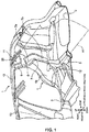
- Fig. 1 is a perspective view in which a portion around a rear wheel house in a vehicle body structure according to the embodiment of the present invention is seen from the inside of a vehicle cabin.
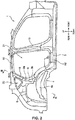
- Fig. 2 is a view in which the rear wheel house and a longitudinal annular structure in the vehicle body structure illustrated in Fig. 1 are seen from an outer surface of a vehicle.
- Fig. 1 only illustrates a right portion of a vehicle body 1.
- the vehicle body 1, to which the vehicle body structure according to this embodiment is applied preferably includes: a floor panel 2 that constitutes a floor surface of the vehicle body 1; a pair of floor side frames 3 that extend substantially in a vehicle longitudinal direction on both sides of the floor panel 2 in a width direction of the vehicle (a right-left direction of the vehicle and will hereinafter be described as a "vehicle width direction"); a pair of the rear wheel houses 4, in each of which a rear wheel (not illustrated) is accommodated; a cross member 5 that extends in the vehicle width direction at a position between the pair of the rear wheel houses 4; and a pair of side plates 6 that constitute side surfaces of the vehicle body 1.
- the rear wheel house 4 preferably includes, as a first portion, a wheel house inner 4a that is positioned inward in the vehicle width direction of the vehicle body 1 and, as a second portion that differs from the first portion, a wheel house outer 4b that is positioned outward in the vehicle width direction of the vehicle body 1.
- Each of the wheel house inner 4a and the wheel house outer 4b is a plate-shaped member that is arranged along the vehicle longitudinal direction and is bulged in a semicircular shape so as to be projected upward.
- the wheel house inner 4a and the wheel house outer 4b respectively have flanges 4c, 4d, each of which extends in a circular shape that is projected outward from a circular outer circumferential surface.
- a lower end of the side plate 6 is joined to a portion where the flanges 4c, 4d are placed over each other by welding or the like.
- the vehicle body structure according to this embodiment further preferably includes an inner rein or inner junction plate 7 as a first reinforcing member, an outer rein or outer junction plate 8 as a second reinforcing member, a meeting section 14, and a damping structure 15 as a damping section.
- the inner rein 7 and the outer rein 8 are provided in a manner to couple the rear wheel house 4 and the side plate 6 on inner and outer sides of the vehicle body 1, and reinforce the vehicle body 1 around the rear wheel house 4.
- the inner rein 7 is the reinforcing member that couples the wheel house inner 4a of the rear wheel house 4 and the side plate 6 as a component constituting the side surface of the vehicle body 1 and that reinforces the vehicle body 1.
- the inner rein 7 has: an upper section 7a that substantially opposes the side plate 6; and a lower section 7b that is located substantially under the upper section 7a and extends toward a vehicle inner side (in the vehicle left direction) along the wheel house inner 4a.
- a flange 7c that expands outward from the outer peripheral edge is formed.
- the flange 7c is joined to the side plate 6 by welding or the like, the upper section 7a of the inner rein 7 is coupled to the side plate 6.
- a flange 7d that expands outward from the outer peripheral edge is formed.
- the flange 7d is joined to the wheel house inner 4a by welding or the like, the lower section 7b of the inner rein 7 is coupled to the wheel house inner 4a.
- the inner rein 7 is a plate-shaped member that is bulged toward the vehicle inner side and, as illustrated in Fig. 3 , constitutes an inner-side substantially closed cross-sectional structure 18 with the side plate 6 and the wheel house inner 4a.
- the outer rein 8 is the reinforcing member that couples the wheel house outer 4b of the rear wheel house 4 and the side plate 6 and reinforces the vehicle body 1.
- the outer rein 8 has: an upper section 8a that substantially opposes the side plate 6; and a lower section 8b that is located under the upper section 8a and extends toward a vehicle outer side (in the vehicle right direction) along the wheel house outer 4b.
- a flange 8c that expands outward from the outer peripheral edge is formed on an outer peripheral edge of the upper section 8a of the outer rein 8.
- the flange 8c is joined to the side plate 6 by welding or the like, the upper section 8a of the outer rein 8 is coupled to the side plate 6.
- a flange 8d that expands outward from the peripheral edge is formed on an outer peripheral edge of the lower section 8b of the outer rein 8.
- the flange 8d is joined to the wheel house outer 4b by welding or the like, the lower section 8b of the outer rein 8 is coupled to the wheel house outer 4b.
- the outer rein 8 is a plate-shaped member that is bulged toward the vehicle outer side and, as illustrated in Fig. 3 , constitutes an outer-side substantially closed cross-sectional structure 19 with the side plate 6 and the wheel house outer 4b.
- the meeting section 14 is a portion where a transmission path of the vibration, which is transmitted along the inner rein 7, and a transmission path of the vibration, which is transmitted along the outer rein 8, meet.
- the meeting section 14 is constructed of the side plate 6, the upper section 7a of the inner rein 7, which substantially opposes the side plate 6, and the upper section 8a of the outer rein 8, which substantially opposes the side plate 6.
- the inner rein 7 has preferably an interrupting section 7e that interrupts the transmission of the vibration along the inner rein 7 in an intermediate portion of the meeting section 14.
- the interrupting section 7e of the inner rein 7 is formed with an upper end of the upper section 7a of the inner rein 7 (more specifically, the flange 7c near the upper end of the upper section 7a).
- the damping structure 15 is arranged in the meeting section 14 and is configured to dampen the vibrations transmitted along the inner rein 7 and the outer rein 8.
- the damping structure 15 in this embodiment is arranged in the outer-side substantially closed cross-sectional structure 19.
- the damping structure 15 preferably includes: a coupling member 16 that is coupled to an inner surface of the outer rein 8; and a vibration damping member 17 that is interposed between the coupling member 16 and the side plate 6 to dampen the vibration.
- the coupling member 16 is a plate-shaped member having such a magnitude of rigidity that the vibration can be transmitted, and has preferably a lower bent section 16a and an upper bent section 16b.
- the lower bent section 16a is a portion that is bent substantially downward to oppose the inner surface of the outer rein 8, and is fixed to the outer rein 8 by welding or the like.
- the upper bent section 16b is a portion that is bent substantially upward to oppose the side plate 6.
- the vibration damping member 17 needs to have viscoelasticity that can convert vibration energy into thermal energy and can thereby dampen the vibration. More specifically, under a condition that a temperature is about 20°C and a frequency of an excitation force is about 30 Hz, the vibration damping member 17 needs to have such a physical property that a storage elastic modulus is equal to or lower than about 500 MPa and a loss factor is equal to or larger than about 0.2. As the vibration damping member 17, a viscoelastic member such as damping glue may be adopted. The vibration damping member 17 is interposed between the upper bent section 16b of the coupling member 16 and the side plate 6.
- a portion near the interrupting section 7e of the inner rein 7 is connected to the outer rein 8 via the damping structure 15.
- the inner rein 7 constitutes a vehicle width direction annular structure A1 as the first annular structure section that has an annular substantially closed cross-sectional structure when seen from front of the vehicle body 1.
- the vehicle width direction annular structure A1 is the annular substantially closed cross-sectional structure that is configured to preferably include: a pair of the inner reins 7 arranged on both sides in the vehicle width direction; the pair of the side plates 6, to which the upper sections 7a of the pair of the inner rein 7 are coupled; a pair of rear pillars 9 that are coupled to upper ends of the pair of the side plates 6; a pair of roof side rails 10 that are coupled to upper ends of the pair of the rear pillars 9 and extend substantially in the vehicle longitudinal direction; a roof rein 11 that couples the pair of the roof side rails 10 and extends in the vehicle width direction; a pair of suspension housings 12 that are coupled to the lower sections 7b of the pair of the inner reins 7; and the cross member 5, both ends of which are coupled to the pair of the suspension housings 12.
- a substantially closed cross section is formed as follows by the above members. That is, with the side plate 6 and the wheel house inner 4a, the inner rein 7 constitutes the inner-side substantially closed cross-sectional structure 18 as described above.
- the side plate 6 forms a substantially closed cross section with the upper section 8a of the outer rein 8 illustrated in Fig. 3 .
- the rear pillar 9 has a substantially closed cross section in which an outer pillar and an inner pillar in hat-shaped cross-sectional shapes are joined to each other.
- the roof side rail 10 has a rectangular cylindrical shape and has a substantially closed cross section.
- the roof rein 11 forms a substantially closed cross section with a roof panel, which is not illustrated.
- the suspension housing 12 forms a substantially closed cross section with the wheel house inner 4a.
- the cross member 5 constitute a substantially closed cross section with the floor panel 2.
- the outer rein 8 constitutes a vehicle longitudinal direction annular structure A2 as the second annular structure section that has an annular substantially closed cross-sectional structure when seen in a side view of the vehicle body 1.
- the longitudinal annular structure A2 is formed in a manner to surround a rear doorway 21.
- the vehicle longitudinal direction annular structure A2 is an annular substantially closed cross-sectional structure that is configured to preferably include: the outer rein 8; the side plate 6, to which the upper section 8a of the outer rein 8 is coupled; the rear pillar 9 that is coupled to the upper end of the side plate 6 and the upper section 8a of the outer rein 8 and extends substantially upward; the roof side rail 10 that is coupled to an upper end of the rear pillar 9 and extends substantially in the vehicle longitudinal direction; a center pillar 13 that extends substantially downward from the roof side rail 10 on a vehicle front side of the rear pillar 9; and a floor side frame 3 that extends substantially in the vehicle longitudinal direction and couples a lower end of the center pillar 13 and the wheel house outer 4b.
- a substantially closed cross section is formed as follows by the above members. That is, with the side plate 6 and the wheel house outer 4b, the outer rein 8 constitutes the outer-side substantially closed cross-sectional structure 19 as described above. As described above, the side plate 6 forms the substantially closed cross section with the upper section 8a of the outer rein 8 illustrated in Fig. 3 . As described above, each of the rear pillar 9 and the roof side rail 10 has the substantially closed cross section. Similar to the rear pillar 9, the center pillar 13 also has a substantially closed cross section in which the outer pillar and the inner pillar in the hat-shaped cross-sectional shapes are joined.
- the floor side frame 3 has a rectangular cylindrical shape and has a substantially closed cross section.
- the vehicle body structure in this embodiment On a far side in the meeting section 14 from the rear wheel house 4 (that is, on an opposite side (an upper side) of the rear wheel house 4 as the vibration source from the damping structure 15 in Fig. 3 ), the vehicle body structure in this embodiment has the rear pillar 9, which is illustrated in Figs. 1 to 2 , as a shared portion that is shared by the vehicle width direction annular structure A1 and the vehicle longitudinal direction annular structure A2.
- the rear pillar 9 as the shared portion can prevent the transmission of the vibration to an occupant when being arranged such that the rear pillar 9 is positioned above a lower end 20a of a quarter window opening 20 that is a side window opening formed in a side portion of the vehicle body 1.
- a lower end position of the rear pillar 9 only needs to be appropriately determined by comparing a vibration transmission prevention effect and a design request.
- the rear pillar 9 may slightly be positioned lower than the lower end 20a of the quarter window opening 20.
Landscapes
- Engineering & Computer Science (AREA)
- Chemical & Material Sciences (AREA)
- Combustion & Propulsion (AREA)
- Transportation (AREA)
- Mechanical Engineering (AREA)
- Body Structure For Vehicles (AREA)
Applications Claiming Priority (1)
| Application Number | Priority Date | Filing Date | Title |
|---|---|---|---|
| JP2019033869A JP7088077B2 (ja) | 2019-02-27 | 2019-02-27 | 車体構造 |
Publications (1)
| Publication Number | Publication Date |
|---|---|
| EP3702249A1 true EP3702249A1 (de) | 2020-09-02 |
Family
ID=69581973
Family Applications (1)
| Application Number | Title | Priority Date | Filing Date |
|---|---|---|---|
| EP20157043.9A Withdrawn EP3702249A1 (de) | 2019-02-27 | 2020-02-13 | Fahrzeugkarosseriestruktur und verfahren zur herstellung davon |
Country Status (4)
| Country | Link |
|---|---|
| US (1) | US11142250B2 (de) |
| EP (1) | EP3702249A1 (de) |
| JP (1) | JP7088077B2 (de) |
| CN (1) | CN111619674A (de) |
Citations (4)
| Publication number | Priority date | Publication date | Assignee | Title |
|---|---|---|---|---|
| JP2013049378A (ja) * | 2011-08-31 | 2013-03-14 | Mazda Motor Corp | 車両の車体構造及びその製造方法 |
| JP5776451B2 (ja) | 2011-08-31 | 2015-09-09 | マツダ株式会社 | 車両の車体構造 |
| JP5790333B2 (ja) | 2011-08-31 | 2015-10-07 | マツダ株式会社 | 車両の車体構造 |
| JP6202060B2 (ja) * | 2015-08-24 | 2017-09-27 | マツダ株式会社 | 車両の車体構造 |
Family Cites Families (20)
| Publication number | Priority date | Publication date | Assignee | Title |
|---|---|---|---|---|
| JPS58152673A (ja) * | 1982-03-08 | 1983-09-10 | Mazda Motor Corp | 自動車の前部車体構造 |
| US4973103A (en) * | 1987-12-11 | 1990-11-27 | Mazda Motor Corporation | Vehicle rear body structure |
| KR20010087448A (ko) * | 1999-12-31 | 2001-09-21 | 이계안 | 자동차의 리어엔드 크로스멤버 보강구조 |
| JP4301271B2 (ja) * | 2006-09-12 | 2009-07-22 | 日産自動車株式会社 | 自動車の車体構造 |
| JP5033461B2 (ja) * | 2007-04-06 | 2012-09-26 | 日野自動車株式会社 | 車両後部構造 |
| DE102008006103B4 (de) * | 2008-01-25 | 2017-12-28 | Dr. Ing. H.C. F. Porsche Aktiengesellschaft | Kraftfahrzeug |
| US7959217B2 (en) * | 2008-08-14 | 2011-06-14 | Honda Motor Co., Ltd. | Modified upper rear door hinge patch |
| DE102009005867B4 (de) * | 2009-01-23 | 2019-01-24 | Dr. Ing. H.C. F. Porsche Aktiengesellschaft | Aufbaustruktur für ein Kraftfahrzeug |
| JP5348547B2 (ja) | 2009-06-10 | 2013-11-20 | スズキ株式会社 | 車体後部構造 |
| DE102010017384B4 (de) * | 2010-06-16 | 2020-07-02 | Dr. Ing. H.C. F. Porsche Aktiengesellschaft | Aufbaustruktur für ein Kraftfahrzeug |
| JP5776450B2 (ja) * | 2011-08-31 | 2015-09-09 | マツダ株式会社 | 車両の車体構造 |
| US8708401B2 (en) * | 2012-03-22 | 2014-04-29 | Ford Global Technologies, Llc | Crash brace for energy management |
| JP5904059B2 (ja) | 2012-08-29 | 2016-04-13 | マツダ株式会社 | 車両の後部車体構造 |
| CN103101579B (zh) * | 2013-01-14 | 2015-07-15 | 奇瑞汽车股份有限公司 | 汽车后减震器传力结构及汽车 |
| JP6107335B2 (ja) * | 2013-04-01 | 2017-04-05 | スズキ株式会社 | 振動抑制構造 |
| WO2015056572A1 (ja) * | 2013-10-18 | 2015-04-23 | 本田技研工業株式会社 | 車体後部構造 |
| KR101611022B1 (ko) * | 2014-03-04 | 2016-04-11 | 현대자동차주식회사 | 차량의 어퍼바디 프레임 시스템 |
| JP6128334B2 (ja) | 2014-07-22 | 2017-05-17 | マツダ株式会社 | 車両の後部車体構造 |
| JP6256429B2 (ja) * | 2015-08-17 | 2018-01-10 | マツダ株式会社 | 車両の車体構造 |
| CN205632669U (zh) * | 2015-11-02 | 2016-10-12 | 阿尔特汽车技术股份有限公司 | 车身环状加强结构 |
-
2019
- 2019-02-27 JP JP2019033869A patent/JP7088077B2/ja active Active
-
2020
- 2020-02-12 CN CN202010088125.XA patent/CN111619674A/zh active Pending
- 2020-02-13 EP EP20157043.9A patent/EP3702249A1/de not_active Withdrawn
- 2020-02-19 US US16/794,274 patent/US11142250B2/en active Active
Patent Citations (4)
| Publication number | Priority date | Publication date | Assignee | Title |
|---|---|---|---|---|
| JP2013049378A (ja) * | 2011-08-31 | 2013-03-14 | Mazda Motor Corp | 車両の車体構造及びその製造方法 |
| JP5776451B2 (ja) | 2011-08-31 | 2015-09-09 | マツダ株式会社 | 車両の車体構造 |
| JP5790333B2 (ja) | 2011-08-31 | 2015-10-07 | マツダ株式会社 | 車両の車体構造 |
| JP6202060B2 (ja) * | 2015-08-24 | 2017-09-27 | マツダ株式会社 | 車両の車体構造 |
Also Published As
| Publication number | Publication date |
|---|---|
| CN111619674A (zh) | 2020-09-04 |
| JP7088077B2 (ja) | 2022-06-21 |
| US11142250B2 (en) | 2021-10-12 |
| US20200269923A1 (en) | 2020-08-27 |
| JP2020138589A (ja) | 2020-09-03 |
Similar Documents
| Publication | Publication Date | Title |
|---|---|---|
| EP3018041B1 (de) | Struktur eines vorderen karosserieaufbauabschnittes | |
| JP5698340B2 (ja) | 車体後部構造 | |
| US9764705B2 (en) | Vehicle connecting member and vehicle front section structure | |
| JP6015619B2 (ja) | 車体フレーム及び車両床下構造 | |
| CN102963437B (zh) | 车辆的车身结构及其制造方法 | |
| JP5549420B2 (ja) | 車両の後部車体構造 | |
| CN110304152B (zh) | 车辆的前部车身结构 | |
| JP2019119299A (ja) | 下部車体構造 | |
| JP6142978B1 (ja) | 車両前部構造 | |
| JP5747270B2 (ja) | 自動車後部における重要保安部品の設置構造 | |
| WO2015001928A1 (ja) | 自動車の車体構造およびフロントサイドフレームの強度設定方法 | |
| JP2019123344A (ja) | 下部車体構造 | |
| WO2015146902A1 (ja) | 車体側部構造 | |
| JP2015003670A (ja) | 車体前部構造 | |
| JPWO2012017747A1 (ja) | エンジンマウント支持構造 | |
| CN112236355B (zh) | 车辆的后部车身结构 | |
| CN105992714B (zh) | 防钻入保护装置的结构 | |
| CN105793117B (zh) | 防钻入保护装置的结构 | |
| CN112109810A (zh) | 车身后部结构 | |
| JP5622045B2 (ja) | パワートレインの支持装置 | |
| US11142250B2 (en) | Vehicle body structure | |
| CN110626432A (zh) | 车身结构和车辆 | |
| CN115214784B (zh) | 一种车身后侧围总成及汽车 | |
| JP2015128942A (ja) | 車両の車体構造 | |
| KR20130076488A (ko) | 차량용 프론트 사이드멤버 |
Legal Events
| Date | Code | Title | Description |
|---|---|---|---|
| PUAI | Public reference made under article 153(3) epc to a published international application that has entered the european phase |
Free format text: ORIGINAL CODE: 0009012 |
|
| STAA | Information on the status of an ep patent application or granted ep patent |
Free format text: STATUS: THE APPLICATION HAS BEEN PUBLISHED |
|
| AK | Designated contracting states |
Kind code of ref document: A1 Designated state(s): AL AT BE BG CH CY CZ DE DK EE ES FI FR GB GR HR HU IE IS IT LI LT LU LV MC MK MT NL NO PL PT RO RS SE SI SK SM TR |
|
| AX | Request for extension of the european patent |
Extension state: BA ME |
|
| STAA | Information on the status of an ep patent application or granted ep patent |
Free format text: STATUS: REQUEST FOR EXAMINATION WAS MADE |
|
| 17P | Request for examination filed |
Effective date: 20210225 |
|
| RBV | Designated contracting states (corrected) |
Designated state(s): AL AT BE BG CH CY CZ DE DK EE ES FI FR GB GR HR HU IE IS IT LI LT LU LV MC MK MT NL NO PL PT RO RS SE SI SK SM TR |
|
| STAA | Information on the status of an ep patent application or granted ep patent |
Free format text: STATUS: THE APPLICATION IS DEEMED TO BE WITHDRAWN |
|
| 18D | Application deemed to be withdrawn |
Effective date: 20220901 |