EP3675931B1 - Système et procédé d'étalonnage de pression d'injecteur - Google Patents
Système et procédé d'étalonnage de pression d'injecteur Download PDFInfo
- Publication number
- EP3675931B1 EP3675931B1 EP18766499.0A EP18766499A EP3675931B1 EP 3675931 B1 EP3675931 B1 EP 3675931B1 EP 18766499 A EP18766499 A EP 18766499A EP 3675931 B1 EP3675931 B1 EP 3675931B1
- Authority
- EP
- European Patent Office
- Prior art keywords
- fluid
- drive member
- sensor
- calibration system
- calibration
- Prior art date
- Legal status (The legal status is an assumption and is not a legal conclusion. Google has not performed a legal analysis and makes no representation as to the accuracy of the status listed.)
- Active
Links
- 238000000034 method Methods 0.000 title description 35
- 239000012530 fluid Substances 0.000 claims description 265
- 230000006835 compression Effects 0.000 claims description 35
- 238000007906 compression Methods 0.000 claims description 35
- 238000011088 calibration curve Methods 0.000 claims description 22
- 238000004891 communication Methods 0.000 claims description 20
- 229920001971 elastomer Polymers 0.000 claims description 6
- 239000000806 elastomer Substances 0.000 claims description 6
- 239000006260 foam Substances 0.000 claims description 6
- 238000006073 displacement reaction Methods 0.000 claims description 5
- FAPWRFPIFSIZLT-UHFFFAOYSA-M Sodium chloride Chemical compound [Na+].[Cl-] FAPWRFPIFSIZLT-UHFFFAOYSA-M 0.000 description 21
- 239000011780 sodium chloride Substances 0.000 description 19
- 238000005259 measurement Methods 0.000 description 18
- 230000007246 mechanism Effects 0.000 description 18
- 238000002347 injection Methods 0.000 description 16
- 239000007924 injection Substances 0.000 description 16
- 239000002872 contrast media Substances 0.000 description 13
- 230000000875 corresponding effect Effects 0.000 description 11
- 229940039231 contrast media Drugs 0.000 description 10
- 238000005096 rolling process Methods 0.000 description 10
- 239000000463 material Substances 0.000 description 9
- 238000003384 imaging method Methods 0.000 description 5
- 239000003795 chemical substances by application Substances 0.000 description 4
- 230000007547 defect Effects 0.000 description 4
- 238000011010 flushing procedure Methods 0.000 description 4
- 230000006870 function Effects 0.000 description 4
- 230000008569 process Effects 0.000 description 4
- 230000005483 Hooke's law Effects 0.000 description 3
- 238000013459 approach Methods 0.000 description 3
- 238000012512 characterization method Methods 0.000 description 3
- 230000009977 dual effect Effects 0.000 description 3
- 239000000203 mixture Substances 0.000 description 3
- 230000003442 weekly effect Effects 0.000 description 3
- 230000005540 biological transmission Effects 0.000 description 2
- 230000015556 catabolic process Effects 0.000 description 2
- 238000006243 chemical reaction Methods 0.000 description 2
- 238000002591 computed tomography Methods 0.000 description 2
- 230000002596 correlated effect Effects 0.000 description 2
- 238000006731 degradation reaction Methods 0.000 description 2
- 238000001514 detection method Methods 0.000 description 2
- 238000005516 engineering process Methods 0.000 description 2
- 230000001788 irregular Effects 0.000 description 2
- 238000002955 isolation Methods 0.000 description 2
- 239000002184 metal Substances 0.000 description 2
- 238000012544 monitoring process Methods 0.000 description 2
- 230000003287 optical effect Effects 0.000 description 2
- 229940071643 prefilled syringe Drugs 0.000 description 2
- 230000001105 regulatory effect Effects 0.000 description 2
- 239000000243 solution Substances 0.000 description 2
- 239000000126 substance Substances 0.000 description 2
- 230000008961 swelling Effects 0.000 description 2
- 238000012360 testing method Methods 0.000 description 2
- 230000002792 vascular Effects 0.000 description 2
- XLYOFNOQVPJJNP-UHFFFAOYSA-N water Chemical compound O XLYOFNOQVPJJNP-UHFFFAOYSA-N 0.000 description 2
- 230000009471 action Effects 0.000 description 1
- 238000004458 analytical method Methods 0.000 description 1
- 238000002583 angiography Methods 0.000 description 1
- 230000008859 change Effects 0.000 description 1
- 238000010276 construction Methods 0.000 description 1
- 238000011109 contamination Methods 0.000 description 1
- 238000012937 correction Methods 0.000 description 1
- 230000002950 deficient Effects 0.000 description 1
- 238000011161 development Methods 0.000 description 1
- 238000002405 diagnostic procedure Methods 0.000 description 1
- 238000013399 early diagnosis Methods 0.000 description 1
- 239000013536 elastomeric material Substances 0.000 description 1
- 238000004401 flow injection analysis Methods 0.000 description 1
- 239000011521 glass Substances 0.000 description 1
- 238000010438 heat treatment Methods 0.000 description 1
- 230000000977 initiatory effect Effects 0.000 description 1
- 238000003780 insertion Methods 0.000 description 1
- 230000037431 insertion Effects 0.000 description 1
- 238000002595 magnetic resonance imaging Methods 0.000 description 1
- 238000004519 manufacturing process Methods 0.000 description 1
- KJLLKLRVCJAFRY-UHFFFAOYSA-N mebutizide Chemical compound ClC1=C(S(N)(=O)=O)C=C2S(=O)(=O)NC(C(C)C(C)CC)NC2=C1 KJLLKLRVCJAFRY-UHFFFAOYSA-N 0.000 description 1
- 238000012986 modification Methods 0.000 description 1
- 230000004048 modification Effects 0.000 description 1
- 230000037361 pathway Effects 0.000 description 1
- 238000002600 positron emission tomography Methods 0.000 description 1
- 238000005381 potential energy Methods 0.000 description 1
- 238000005067 remediation Methods 0.000 description 1
- 230000008439 repair process Effects 0.000 description 1
- 230000000452 restraining effect Effects 0.000 description 1
- 238000002560 therapeutic procedure Methods 0.000 description 1
- 238000013519 translation Methods 0.000 description 1
- -1 tubing diameter Substances 0.000 description 1
- 238000002604 ultrasonography Methods 0.000 description 1
- 230000003313 weakening effect Effects 0.000 description 1
Images


Classifications
-
- A—HUMAN NECESSITIES
- A61—MEDICAL OR VETERINARY SCIENCE; HYGIENE
- A61M—DEVICES FOR INTRODUCING MEDIA INTO, OR ONTO, THE BODY; DEVICES FOR TRANSDUCING BODY MEDIA OR FOR TAKING MEDIA FROM THE BODY; DEVICES FOR PRODUCING OR ENDING SLEEP OR STUPOR
- A61M5/00—Devices for bringing media into the body in a subcutaneous, intra-vascular or intramuscular way; Accessories therefor, e.g. filling or cleaning devices, arm-rests
- A61M5/14—Infusion devices, e.g. infusing by gravity; Blood infusion; Accessories therefor
- A61M5/142—Pressure infusion, e.g. using pumps
-
- G—PHYSICS
- G01—MEASURING; TESTING
- G01F—MEASURING VOLUME, VOLUME FLOW, MASS FLOW OR LIQUID LEVEL; METERING BY VOLUME
- G01F25/00—Testing or calibration of apparatus for measuring volume, volume flow or liquid level or for metering by volume
- G01F25/10—Testing or calibration of apparatus for measuring volume, volume flow or liquid level or for metering by volume of flowmeters
- G01F25/17—Testing or calibration of apparatus for measuring volume, volume flow or liquid level or for metering by volume of flowmeters using calibrated reservoirs
-
- A—HUMAN NECESSITIES
- A61—MEDICAL OR VETERINARY SCIENCE; HYGIENE
- A61M—DEVICES FOR INTRODUCING MEDIA INTO, OR ONTO, THE BODY; DEVICES FOR TRANSDUCING BODY MEDIA OR FOR TAKING MEDIA FROM THE BODY; DEVICES FOR PRODUCING OR ENDING SLEEP OR STUPOR
- A61M5/00—Devices for bringing media into the body in a subcutaneous, intra-vascular or intramuscular way; Accessories therefor, e.g. filling or cleaning devices, arm-rests
- A61M5/14—Infusion devices, e.g. infusing by gravity; Blood infusion; Accessories therefor
- A61M5/142—Pressure infusion, e.g. using pumps
- A61M5/145—Pressure infusion, e.g. using pumps using pressurised reservoirs, e.g. pressurised by means of pistons
- A61M5/1452—Pressure infusion, e.g. using pumps using pressurised reservoirs, e.g. pressurised by means of pistons pressurised by means of pistons
- A61M5/14546—Front-loading type injectors
-
- A—HUMAN NECESSITIES
- A61—MEDICAL OR VETERINARY SCIENCE; HYGIENE
- A61M—DEVICES FOR INTRODUCING MEDIA INTO, OR ONTO, THE BODY; DEVICES FOR TRANSDUCING BODY MEDIA OR FOR TAKING MEDIA FROM THE BODY; DEVICES FOR PRODUCING OR ENDING SLEEP OR STUPOR
- A61M5/00—Devices for bringing media into the body in a subcutaneous, intra-vascular or intramuscular way; Accessories therefor, e.g. filling or cleaning devices, arm-rests
- A61M5/178—Syringes
- A61M5/20—Automatic syringes, e.g. with automatically actuated piston rod, with automatic needle injection, filling automatically
-
- F—MECHANICAL ENGINEERING; LIGHTING; HEATING; WEAPONS; BLASTING
- F16—ENGINEERING ELEMENTS AND UNITS; GENERAL MEASURES FOR PRODUCING AND MAINTAINING EFFECTIVE FUNCTIONING OF MACHINES OR INSTALLATIONS; THERMAL INSULATION IN GENERAL
- F16K—VALVES; TAPS; COCKS; ACTUATING-FLOATS; DEVICES FOR VENTING OR AERATING
- F16K37/00—Special means in or on valves or other cut-off apparatus for indicating or recording operation thereof, or for enabling an alarm to be given
- F16K37/0075—For recording or indicating the functioning of a valve in combination with test equipment
- F16K37/0083—For recording or indicating the functioning of a valve in combination with test equipment by measuring valve parameters
-
- G—PHYSICS
- G05—CONTROLLING; REGULATING
- G05D—SYSTEMS FOR CONTROLLING OR REGULATING NON-ELECTRIC VARIABLES
- G05D15/00—Control of mechanical force or stress; Control of mechanical pressure
- G05D15/01—Control of mechanical force or stress; Control of mechanical pressure characterised by the use of electric means
-
- A—HUMAN NECESSITIES
- A61—MEDICAL OR VETERINARY SCIENCE; HYGIENE
- A61M—DEVICES FOR INTRODUCING MEDIA INTO, OR ONTO, THE BODY; DEVICES FOR TRANSDUCING BODY MEDIA OR FOR TAKING MEDIA FROM THE BODY; DEVICES FOR PRODUCING OR ENDING SLEEP OR STUPOR
- A61M5/00—Devices for bringing media into the body in a subcutaneous, intra-vascular or intramuscular way; Accessories therefor, e.g. filling or cleaning devices, arm-rests
- A61M5/14—Infusion devices, e.g. infusing by gravity; Blood infusion; Accessories therefor
- A61M5/142—Pressure infusion, e.g. using pumps
- A61M2005/14288—Infusion or injection simulation
-
- A—HUMAN NECESSITIES
- A61—MEDICAL OR VETERINARY SCIENCE; HYGIENE
- A61M—DEVICES FOR INTRODUCING MEDIA INTO, OR ONTO, THE BODY; DEVICES FOR TRANSDUCING BODY MEDIA OR FOR TAKING MEDIA FROM THE BODY; DEVICES FOR PRODUCING OR ENDING SLEEP OR STUPOR
- A61M2205/00—General characteristics of the apparatus
- A61M2205/33—Controlling, regulating or measuring
- A61M2205/332—Force measuring means
-
- A—HUMAN NECESSITIES
- A61—MEDICAL OR VETERINARY SCIENCE; HYGIENE
- A61M—DEVICES FOR INTRODUCING MEDIA INTO, OR ONTO, THE BODY; DEVICES FOR TRANSDUCING BODY MEDIA OR FOR TAKING MEDIA FROM THE BODY; DEVICES FOR PRODUCING OR ENDING SLEEP OR STUPOR
- A61M2205/00—General characteristics of the apparatus
- A61M2205/50—General characteristics of the apparatus with microprocessors or computers
-
- A—HUMAN NECESSITIES
- A61—MEDICAL OR VETERINARY SCIENCE; HYGIENE
- A61M—DEVICES FOR INTRODUCING MEDIA INTO, OR ONTO, THE BODY; DEVICES FOR TRANSDUCING BODY MEDIA OR FOR TAKING MEDIA FROM THE BODY; DEVICES FOR PRODUCING OR ENDING SLEEP OR STUPOR
- A61M2205/00—General characteristics of the apparatus
- A61M2205/70—General characteristics of the apparatus with testing or calibration facilities
Definitions
- the present disclosure relates generally to systems and methods for calibrating a fluid injector, such as a medical fluid injector, and, further, to a system and method for pressure calibration of the fluid injector.
- a medical practitioner such as a physician injects a patient with one or more medical fluids.
- a number of fluid delivery systems having injector-actuated syringes and fluid injectors for pressurized injection of fluids, such as a contrast solution (often referred to simply as "contrast"), a flushing agent, such as saline, and other medical fluids have been developed for use in procedures such as angiography (CV), computed tomography (CT), ultrasound, magnetic resonance imaging (MRI), positron emission tomography (PET), and other imaging procedures.
- these fluid delivery systems are designed to deliver preset amounts of a contrast fluid, a saline flushing agent, and mixtures thereof at desired flow rates over a predetermined time.
- An actual flow rate (or delivered volume) of fluid that is delivered to the patient is targeted to be as close as possible to the desired flow rate (or desired volume).
- the actual performance of the fluid delivery system is a function of many factors due to overall impedance and capacitance of the fluid delivery system.
- impedance and capacitance of the fluid delivery system may cause a fluid flow over-rate or under-rate (or volume over- or under-delivery) from a desired flow rate (or desired volume).
- a calibration system for calibrating a pressure output of a drive member of a fluid injector according to claim 1 is provided.
- the calibration system may be a fluidless calibration system, which may be readily utilized between several different fluid injection systems on site and/or by an imaging technician without the presence of a trained service technician.
- the calibration system may store data on drive members of a fluid injector over a period of time and determine if, how, and when the drive member falls out of specification.
- the calibration system may be utilized for each drive member of a fluid injector, such as a fluid injector with one, two, three, or even more drive members.
- the calibration system may be suited to calibrate the motor force of a fluid injector having one or more pistons as drive members, such as a syringe based fluid injector system, for example a fluid injector having one, two, three, or more pistons for operatively engaging corresponding plungers or piston engagement members of one, two, three, or more syringes.
- a fluid injector having one or more pistons as drive members
- a syringe based fluid injector system for example a fluid injector having one, two, three, or more pistons for operatively engaging corresponding plungers or piston engagement members of one, two, three, or more syringes.
- the calibration system comprises a housing configured for connecting to the fluid injector; a drive member engagement portion configured for contacting a drive member of the fluid injector; a compressible member connected at its proximal end to the drive member engagement portion; and a sensor connected to the compressible member.
- the compressible member is compressed with movement of the drive member of the fluid injector between a first, uncompressed position and a second, at least partially compressed position of the fluid injector in a distal direction.
- the sensor is configured for measuring a force imparted by the drive member when the compressible member is in the second, at least partially compressed position compared to when the drive member is in the first, uncompressed position.
- the sensor may be a strain gauge, a force sensor, a load cell, a pressure sensor, a force transducer, and combination of any thereof.
- the sensor is a strain gauge and in other embodiments the sensor is a force sensor.
- the compressible member may be a spring, a plurality of springs, a pneumatic compression cell, a hydraulic compression cell, a compressible foam, an elastomer, and combinations of any thereof.
- the compressible member is a spring.
- the sensor may be in wired or wireless communication with a processor of the fluid injector and an output of the sensor may be transmitted to the processor.
- the output of the sensor may be used to calibrate an input to one or more of a motor, the drive member, a ball screw in mechanical communication with the motor and the drive member, a frictional component from a disposable fluid delivery reservoir, and other compressible mechanical components.
- the output of the sensor may be used to generate a calibration curve for calibrating a pressure output of the drive member of the fluid injector.
- the calibration curve is utilized to determine a fault condition, such as, for example, a warning that the drive member or motor may need servicing.
- the present disclosure describes a calibration system for calibrating a pressure output of a drive member of fluid injector
- the calibration system comprises: a housing configured for connecting to the fluid injector; a drive member engagement portion configured for contacting a drive member of the fluid injector; a compressible member having a known modulus of compression connected at its proximal end to the drive member engagement portion; and a sensor connected to the compressible member.
- the compressible member may be compressed with movement of the drive member of the fluid injector between a first, uncompressed position and a second, at least partially compressed position of the fluid injector in a distal direction.
- the sensor may be configured for measuring a displacement of the drive member when the compressible member is in the second, at least partially compressed position compared to when the drive member is in the first, uncompressed position.
- the compressible member may be selected from a spring, a plurality of springs, a pneumatic compression cell, a hydraulic compression cell, a compressible foam, an elastomer, or combinations of any thereof.
- the compressible member is a spring.
- the sensor may be in wired or wireless communication with a processor of the fluid injector and an output of the sensor may be transmitted to the processor.
- the processor may determine the pressure output of the drive member of the fluid injector from the output of the sensor and the modulus of compression of the compressible member.
- the output of the sensor may be used to generate a calibration curve for calibrating the pressure output of a drive member of the fluid injector.
- the calibration curve is utilized to determine a fault condition, such as, for example, a warning that the drive member or motor may need servicing.
- the calibration system can be regularly used to track changes in load for the drive member over time.
- the calibration system may be utilized daily, weekly, monthly, or at other regular or irregular intervals to track changes in the calibration of the injector.
- the calibrations may be done by the imaging technician without need for service calls from the injector manufacturer representatives or third party servicing technicians.
- the calibrations may be recorded over a period of time and may be used by a servicing technician to determine whether specific services may be required. Changes in calibration of the injector that fall outside of expected values and tolerances may signify potential unexpected wear or defects with the injector system and allow early detection and servicing.
- a method of calibrating a pressure output of a drive member of a fluid injector may comprise: connecting a calibration system to the fluid injector; contacting a drive member of the fluid injector with the drive member engagement portion of the calibration system; driving a motor of the fluid injector to move the drive member and compress the compressible member from a first, uncompressed positon to a second, at least partially compressed position; and generating a measurement signal by a sensor based on the a force imparted on the compressible member by the drive member or the displacement of the drive member when the compressible member is in the second, at least partially compressed position.
- the methods may be used by any of the various embodiments of the calibration systems described herein.
- the method may further include sending the measurement signal to a processor of the fluid injector to calibrate a pressure output of the drive member based on the measurement signal.
- the methods may include generating a calibration curve for the pressure output of the drive member. The method may further include comparing a calibration measurement signal with one or more previous measurement signals and/or with a predetermined calibration value to determine if the injector calibration falls outside of tolerances.
- the various embodiments of the calibration system provide useful data related to force applied by a drive member in a single stroke across an entire expected load regime.
- Conventional fluid calibration has a fixed orifice which reaches a set pressure when the drive member is moved at a standard speed. This requires collection of multiple different pressure points to generate a calibration profile for several drive speeds.
- the sensor determines all loads at a given speed in a single stroke of the drive member. As the compressible member is compressed, the system travels through the entire expected load regime in a single stroke.
- proximal refers to a portion of a syringe and/or a plunger nearest a fluid injector when a syringe and/or a plunger is oriented for connecting to a fluid injector.
- distal refers to a portion of a syringe and/or a plunger farthest away from a fluid injector when a syringe and/or a plunger is oriented for connecting to a fluid injector.
- radial refers to a direction in a cross-sectional plane normal to a longitudinal axis of a syringe, a plunger, and/or a piston extending between proximal and distal ends.
- circumferential refers to a direction around an inner or outer surface of a sidewall of a syringe, a plunger, and/or a piston.
- axial refers to a direction along a longitudinal axis of a syringe, a piston, and/or a piston extending between the proximal and distal ends.
- open when used to refer to a fluid delivery component means that the system is in fluid connection with an outlet, for example through a nozzle or the open end of a tubing component or catheter.
- fluid flow may be constrained, for example by forcing a fluid through a small diameter fluid path where flow may be determined by physical parameters of the system and the fluid, such as tubing diameter, fluid path constrictions, applied pressure, viscosity, etc.
- closed when used to refer to a fluid delivery component means that the system is not in fluid connection with an outlet, for example where fluid flow is stopped by a valve, such as a stopcock, high crack pressure valve, pinch valve, and the like.
- Characterizing an impedance of a fluid delivery system to minimize a difference between desired and actual fluid delivery system performance requires consideration of how energy from an energy source, such as a pressurizing mechanism, for example a drive member such as a piston attached to a motor, is used in or moves through the system.
- the energy output or loss from the fluid delivery system may be in the form of heat losses through frictional forces or of work done on the fluid delivery system. For example, some of the energy carried by the pressurized fluid as it is delivered under pressure through a catheter is lost through resistive, frictional, or dissipative heating of the fluid.
- pressurized delivery of fluid can also increase the potential energy of the system in terms of an increase in overall volume of system components and/or compressive forces on system components, as discussed herein.
- system components may expand or may compress under the stress or load imparted by the pressurized fluid in a closed or open system.
- the kinetic energy of pressurized fluid moving through the fluid delivery system can affect the overall performance of the fluid delivery system.
- inertial forces of moving contrast media, saline, compression of system mechanical components, and expansion of the reservoirs, syringes, and/or tubing associated with the system may cause a phase lag between movement of the syringe plunger within the injector syringe and movement of contrast material out of the catheter and into the patient.
- Total system capacitance (also referred to as compliance or elasticity) represents the volume of fluid (i.e., change in volume, such as excess volume) that is captured in the swelling of components of the fluid delivery system and compression of mechanical components.
- capacitance is directly correlative to injection pressure and directly correlative to volume of contrast medium and saline in the syringes. In other words, capacitance increases with an increase in injection pressure and an increase in volume of fluid in the syringes.
- Total system capacitance is inherent to each fluid delivery system and depends on a plurality of factors beyond pressure and volume of fluid remaining in the system, including, without limitation, fluid properties (such as viscosity, temperature, etc.), injector construction, mechanical properties of materials used to construct the syringe or reservoir, plunger, pressure jacket surrounding the syringe, fluid lines delivering the fluid to the patient, size of the syringe, plunger, pressure jacket, diameter of tubing or other orifices through which the fluid must pass under pressure, and fluid properties, such as temperature, viscosity, and density. System capacitance may result in discrepancies between programed fluid volume delivery and actual volume delivery.
- fluid properties such as viscosity, temperature, etc.
- initial pressurization may result in swelling of system components under fluid pressure and/or compression of mechanical components under force, rather than delivery of a corresponding fluid volume to a patient.
- the pressurizing force is reduced or released during a portion of the injection, for example when the desired fluid volume is delivered, the release of the stored capacitance-based volume may result in over delivery of fluid.
- fluid delivery systems such as fluid delivery systems having a single syringe, two syringes (for example a contrast media syringe and a saline flush syringe), three syringes (for example two contrast syringes, which may contain the same or different contrast media or different concentrations, and a saline flush syringe) or a plurality of syringes, each independently driven by pistons or drive members of the fluid injector, the accuracy of fluid delivery is based, at least in part, on the ability of the fluid injector to accurately characterize the pressure in the syringe(s) and fluid path(s).
- the accuracy of fluid delivery is based, at least in part, on the ability of the fluid injector to accurately characterize the pressure in the syringe(s) and fluid path(s).
- This characterization may be based, at least in part, on calibrating the piston/drive member using a calibration station configured for accurately measuring the pressure imparted on a fluid by the piston/drive member.
- Pressure calibration of fluid injectors may be performed by pushing fluid at varying rates through a frictionless fixture with a fixed orifice. Pressure of the fluid may then be measured using a pressure gauge, where a real pressure signal is either recorded or fed back into the fluid injector to correlate the load signal of the piston, such as voltage or current measurement, to a real pressure value.
- Conventional calibration stations which involve pressurization of fluid filled syringes and measurement of resulting fluid pressures can be cumbersome, difficult to set up and operate, and have compounded errors, leading to inaccurate pressure characterization of the piston or drive member.
- errors which may affect calibration measurements may include friction in the fixture, air in the fluid path, lack of data points on a correlative timescale, fluid leakage inaccuracies, and gauge reading inaccuracies.
- conventional calibration does not readily provide for real-time adjustment based on factors, such as component wear, differences in syringe tolerance, fluid characteristics, and volumes of syringes used since it is typically performed infrequently, such as when the injector is serviced. Changes in tolerances and system wear in injector components can add up over time to increase volume inaccuracies, creating error in previous calibrations of the volume accuracies of fluid delivery.
- a calibration system which can quickly and accurately measure and calibrate pressurization forces in a fluid injector system, such as for drive members or pistons.
- the calibration system may be readily used by a imaging technician, for example on a daily, weekly, and/or monthly basis to measure and monitor the calibration of a fluid injector system over time and further, may allow for calibration corrections for more accurate fluid delivery.
- the calibration system may work with a processor to track system characteristics over time, providing information about component status over time to determine whether system components are operating within specification or are in need of servicing or replacement.
- the calibration system may comprise a housing configured for connecting to and/or engaging with the fluid injector; a drive member engagement portion configured for contacting an a drive member of the fluid injector; a compressible member connected at its proximal end to the drive member engagement portion; and a sensor connected to the compressible member.
- the compressible member may be compressed with movement of the drive member of the fluid injector between a first, uncompressed position and a second, at least partially compressed position of the fluid injector in a distal direction.
- the sensor may be configured for measuring a force imparted by the drive member when the compressible member is in the second, at least partially compressed position compared to when the drive member is in the first, uncompressed position.
- the sensor may be a strain gauge, a force sensor, a load cell, a pressure sensor, a force transducer, and combination of any thereof.
- the force applied may be calculated utilizing an algorithm, such as Hooke's Law.
- the sensor is a strain gauge and in other embodiments the sensor is a force sensor.
- the compressible member may be a spring, a plurality of springs, a pneumatic compression cell, a hydraulic compression cell, a compressible foam, an elastomer, an opposing ferro- or electromagnetic repulsive force (which may be varied) to provide resistance to drive member movement, a deflectable metal member, and combinations of any thereof.
- the compressible member is a spring.
- the sensor may be in wired or wireless (e.g., by WiFi network, Bluetooth, Ethernet, or other conventional wireless communication technology) communication with one or more of a processor of the fluid injector, an external processor, and a hospital information network, and an output of the sensor may be transmitted to the one or more of a processor of the fluid injector, an external processor, and a hospital information network.
- the output of the sensor may be used to calibrate an input to one or more of a motor, the drive member, a ball screw in mechanical communication with the motor and the drive member, a frictional component from a disposable fluid delivery reservoir, and other compressible mechanical components.
- the output of the sensor may be used to generate a calibration curve for calibrating a pressure output of the drive member of the fluid injector.
- the calibration curve is utilized to determine a fault condition, such as, for example, a warning that the drive member or motor may need servicing.
- a processor may notice gradual or sudden deviations in the pressure calibration which may be the result of degradation of or out-of-specification readings for one or more system components
- the present disclosure describes a calibration system for calibrating a pressure output of a drive member of fluid injector
- the calibration system comprises: a housing configured for connecting to the fluid injector; a drive member engagement portion configured for contacting a drive member of the fluid injector; a compressible member having a known modulus of compression connected at its proximal end to the drive member engagement portion; and a sensor connected to the compressible member.
- the compressible member may be compressed with movement of the drive member of the fluid injector between a first, uncompressed position and a second, at least partially compressed position of the fluid injector in a distal direction.
- the sensor may be configured for measuring a displacement of the drive member when the compressible member is in the second, at least partially compressed position compared to when the drive member is in the first, uncompressed position.
- the compressible member may be selected from a spring, a plurality of springs, a pneumatic compression cell, a hydraulic compression cell, a compressible foam, an elastomer, or combinations of any thereof.
- the compressible member is a spring.
- the sensor may be in wired or wireless communication with a processor of the fluid injector and an output of the sensor may be transmitted to the processor.
- the processor may determine the pressure output of the drive member of the fluid injector from the output of the sensor and the modulus of compression of the compressible member.
- the force that must be applied to the compressible member to compress from the first state to the second state may be calculated.
- the compressible member is a spring having a known spring constant
- the modulus of compression may be initially determined by applying a known force of compression and measuring the distance of compression and developing an equation that shown the functional relationship between the force of compression and distance compressed. This equation may then be utilized by a processor to calculate the force of compression applied to the calibration system according to various embodiments.
- the output of the sensor may be used to generate a calibration curve for calibrating the pressure output of a drive member of the fluid injector.
- the calibration curve is utilized to determine a fault condition, such as, for example, a warning that the drive member or motor may need servicing.
- the calibration system can be regularly used to track changes in load for the drive member over time.
- the calibration system may be utilized daily, weekly, monthly, or at other regular or irregular intervals to track changes in the calibration of the injector.
- the calibrations may be done by the imaging technician without need for service calls from the injector manufacturer representatives or third party servicing technicians.
- the calibrations may be recorded over a period of time and may be used by a servicing technician to determine whether specific services may be required. Changes in calibration of the injector that fall outside of expected values, specifications, and tolerances may signify potential unexpected defects or general wear with one or more components of the injector system and allow early detection and servicing.
- Injector components that may show defects or wear include but are not limited to motors, drive trains, ball drives, gearing, drive member components, syringe and/or plunger engagement or locking mechanisms, restraining members and components that restrain or engage one or more disposable or reusable components, electromechanical components, etc.
- a method of calibrating a pressure output of a drive member of a fluid injector may comprise: connecting a calibration system to the fluid injector; contacting a drive member of the fluid injector with the drive member engagement portion of the calibration system; driving a motor of the fluid injector to move the drive member and compress the compressible member from a first, uncompressed positon to a second, at least partially compressed position; and generating a measurement signal by a sensor based on the a force imparted on the compressible member by the drive member or the displacement of the drive member when the compressible member is in the second, at least partially compressed position.
- the methods may be used by any of the various embodiments of the calibration systems described herein.
- the method may further include sending the measurement signal to one or more of a processor of the fluid injector, an external processor, a hospital information system, and to a manufacturer or service provider to calibrate a pressure output of the drive member based on the measurement signal.
- the methods may include generating a calibration curve for the pressure output of the drive member. The method may further include comparing a calibration measurement signal with one or more previous measurement signals and/or with a predetermined calibration value to determine if the injector calibration falls outside of specifications or tolerances.
- a calibration curve may be created as a factory setting and/or may be generated and updated continuously by the processor, so that sudden deviations from the calibration curve may indicate degradation of operation outside of specifications or tolerances, imminent failure, or failure of one or more injector components.
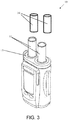
- a fluid injector 10 such as an automated or powered fluid injector, is adapted to interface with and actuate one or more syringes 12 (hereinafter referred to as “syringe 12 "), which may be filed with a fluid F , such as contrast media, saline solution, or any desired medical fluid.
- the injector 10 may be used during a medical procedure to inject the medical fluid into the body of a patient by driving a plunger 14 of each syringe 12 with a drive member, such as piston 19 (shown in FIG. 2 ), such as linear actuator or a piston element.
- the injector 10 may be a multi-syringe injector having two, three or more syringes, wherein the several syringes 12 may be oriented in a side-by-side or other relationship and may be separately actuated by respective drive members/pistons 16 associated with the injector 10 .
- the injector 10 may be configured to deliver fluid from one or both of the syringes 12 , sequentially or concurrently.
- the fluid injector 10 may be a dual head injector having two syringes 12a and 12b , a first syringe 12a for delivering a contrast media or other medical fluid and a second syringe 12b for delivering saline or other medically approved flushing agent to flush the contrast media to the patient.
- the fluid injector 10 may have three syringes 12 , a first and second syringe for delivering one or two different contrast media or other medical fluid and a third syringe for delivering saline or other medically approved flushing agent to flush the contrast media to the patient.
- the fluid injector 10 may be configured to deliver the contrast and saline separately (e.g., delivering a specific volume saline over a specific time followed by delivering a specific volume of contrast over a specific time, followed by a second volume of saline over a specified time to flush the contrast media from the tubing into the patient).
- the fluid injector 10 may be configured to deliver the contrast and saline separately or as a mixture (e.g., delivering a specific volume saline over a specific time followed by delivering a specific volume of contrast, delivering a specific volume contrast over a specific time followed by delivering a specific volume of saline, or a volume of contrast followed by a specified ratio of contrast and saline (i.e., in a "dual flow" process) over a specific time, followed by a second volume of saline over a specified time to flush the contrast media from the tubing into the patient).
- a mixture e.g., delivering a specific volume saline over a specific time followed by delivering a specific volume of contrast, delivering a specific volume contrast over a specific time followed by delivering a specific volume of saline, or a volume of contrast followed by a specified ratio of contrast and saline (i.e., in a "dual flow" process) over a specific time
- a technician may program a specific injection protocol into the injector (or use a pre-written protocol) to deliver the desired volumes of saline, contrast, specific ratios of contrast and saline mixtures, etc., at a desired flow rate, time, and volume for each solution.
- the fluid injector 10 may have at least one bulk fluid source (not shown) for filling the syringes 12a,b with fluid and in certain embodiments, the fluid injector 10 may have a plurality of bulk fluid source, one for each of the plurality of syringes, for filling each of the plurality of syringes with the desired fluid.
- a fluid path set 17 may be in fluid communication with each syringe 12 to place each syringe in fluid communication with a catheter for delivering the fluid F from each syringes 12 to a catheter (not shown) inserted into a patient at a vascular access site.
- fluid flow from the one or more syringes 12 may be regulated by a fluid control module (not shown) that operates various valves, stopcocks, and flow regulating structures to regulate the delivery of the saline solution and contrast to the patient based on user selected injection parameters, such as injection flow rate, duration, total injection volume, and ratio of fluids from the syringes 12 , including specific ratios of each fluid in a dual flow injection protocol.
- the drive member 19 such as a reciprocally driven piston moved by a motor 31 , may be configured to extend into and from the respective syringe port 13 through an opening in the front end of the injector housing.
- a separate drive member/piston 19 may be provided for each syringe 12 .
- Each drive member/piston 19 is configured to impart a motive force to at least a portion of the syringe 12 , such as the plunger 14 or a distal end of a rolling diaphragm syringe (for example, as described in PCT/US2017/056747 ; WO 2016/172467 ; and WO 2015/164783 ).
- the drive member or piston 19 may be reciprocally operable via electro-mechanical drive components such as a ball screw shaft driven by the motor 31 , a voice coil actuator, a rack-and-pinion gear drive, a linear motor, a linear actuator, and the like.
- the motor 31 may be an electric motor.
- Suitable front-loading fluid injectors 10 are disclosed in U.S. Patent Nos. 5,383,858 ; 7,553,294 ; 7,666,169 ; 9,173,995 ; 9,199,033 ; and 9,474,857 ; and in PCT Application Publication No. WO 2016/191485 and WO 2016/112163 .
- the syringe 12 generally has a cylindrical syringe barrel 18 formed from glass, metal, or a suitable medical-grade plastic.
- the barrel 18 has a proximal end 20 and a distal end 24 , with a sidewall 119 extending therebetween along a length of a longitudinal axis 15 extending through a center of the barrel 18 .
- the distal end 24 may have a conical shape that narrows in a distal direction from the cylindrical barrel 18 .
- a nozzle 22 extends from the distal end 24 .
- the barrel 18 has an outer surface 21 and an inner surface 23 with an interior volume 25 configured for receiving the fluid therein.
- the proximal end 20 of the barrel 18 may be sealed with the plunger 14 that is reciprocally movable through the barrel 18 by reciprocal movement of the corresponding piston 19 or drive member.
- the plunger 14 forms a liquid-tight seal against the inner surface 23 of the barrel 18 as the plunger 14 is advanced moved through the barrel 18 .
- the proximal end 20 of the syringe 12 is sized and adapted for being removably inserted in a syringe port 13 of an injector 10 (shown in FIG. 1 ).
- the proximal end 20 of the syringe 12 defines an insertion section 30 that is configured to be removably inserted into the syringe port 13 of the injector 10 while the remaining portion of the syringe 12 remains outside of the syringe port 13 .
- the syringe 12 may be made of any suitable medical-grade plastic or polymeric material, desirably a clear or substantially translucent plastic material.
- the material of the syringe 12 is desirably selected to meet the required tensile and planar stress requirements, water vapor transmission, and chemical/biological compatibility. Exemplary syringes suitable for use with the injector 10 depicted in FIG. 1 are described in United States Patent Nos. 5,383,858 ; 6,322,535 ; 6,652,489 ; 9,173,995 ; and 9,199,033 .
- the injector 10 may be configured for receiving and retaining a pressure jacket 32 within each syringe port 13 of the injector 10 .
- FIGS. 1 and 3 illustrate fluid injectors 10 with two syringe ports 13 , which for the injector 10 shown in FIG. 3 each having a corresponding pressure jacket 32
- other examples of the fluid injector 10 may include a single syringe port 13 and optionally, a corresponding pressure jacket 32 or more than two syringe ports 13 with an optional corresponding number of pressure jackets 32 .
- each pressure jacket 32 may be configured to receive a syringe, such as a syringe for an angiographic (CV) procedure, or a rolling diaphragm syringe 34 (suitable examples of which are described in described in PCT/US2017/056747 ; WO 2016/172467 ; and WO 2015/164783 ).
- a fluid path set similar to the fluid path set 17 shown in FIG. 1 , may be fluidly connected with a discharge end of each rolling diaphragm syringe 34 for delivering fluid from the syringes 34 through tubing connected to a catheter, needle, or other fluid delivery connection (not shown) inserted into a patient at a vascular access site.
- the syringe 12 or 34 may be a pre-filled syringe, i.e., the syringe may be prefilled with a medical fluid, such as a contrast agent or saline, when provided by the syringe manufacturer.
- the pre-filled syringe may be required to be spiked or otherwise punctured at the discharge end prior to an injection procedure to allow fluid to be expelled from the syringe into a fluid line to the patient, as described herein.
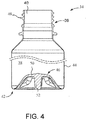
- the rolling diaphragm syringe 34 generally includes a hollow body 36 defining an interior volume 38 .
- the body 36 has a forward or distal end 40 , a rearward or proximal end 42 , and a flexible sidewall 44 extending therebetween.
- the proximal end 42 may be configured to act as piston to pressurize the syringe interior to draw in or expel fluid therefrom, as described herein.
- the sidewall 44 of the rolling diaphragm syringe 34 defines a soft, pliable or flexible, yet self-supporting body that is configured to roll upon itself, as a "rolling diaphragm", under the action of the a drive member or piston of the fluid injector 10 .
- the drive member/piston 19 may be configured to releasably engage a drive member engagement portion 52 at the proximal end 42 of the rolling diaphragm syringe 34 (examples of which are described in PCT/US2017/056747 ).
- the sidewall 44 is configured to roll such that its outer surface is folded and inverted in a radially inward direction as the drive member/piston 19 moves the proximal end 42 in a distal direction and unrolled and unfolded in the opposite manner in a radially outward direction as the drive member/piston 19 retract the proximal end 42 in a proximal direction.
- the rearward or proximal portion of the sidewall 44 connects to a closed end wall 46 , and a forward or distal portion of the sidewall 44 defines a discharge neck 48 opposite the closed end wall 46 .
- the closed end wall 46 may have a concave shape to facilitate the initiation of the inversion or rolling of the sidewall 44 , enhance mechanical strength of the closed end wall 46 , and/or to provide a receiving pocket to receive a distal end of drive member/piston 19 .
- the closed end wall 46 may define a receiving end pocket for interfacing directly with a similarly-shaped distal end of the drive member/piston 19 .
- At least a portion of the drive member/piston 19 may be shaped to substantially match the shape of the closed end wall 46 or, alternatively, pressure from the drive member/piston 19 as it is moved distally may conform the end wall 46 to substantially match the shape of at least a portion of the drive member/piston 19 .
- the end wall 46 may have a central portion 50 having a substantially dome-shaped structure and a drive member engagement portion 52 extending proximally from the central portion 50 .
- the drive member engagement portion 52 is configured for releasably interacting with a corresponding engagement mechanism on the drive member/piston 19 of the fluid injector 10 , for example as the drive member/piston is retracted.
- the rolling diaphragm syringe 34 may be made of any suitable medical-grade plastic or polymeric material, desirably a clear or substantially translucent plastic material. The material of the rolling diaphragm syringe 34 is desirably selected to meet the required tensile and planar stress requirements, water vapor transmission, and chemical/biological compatibility.
- a fluid injector 10 is illustrated in accordance with another example of the present disclosure.
- the injector 10 has a housing 54 that encloses various mechanical drive components and electrical and power components necessary to drive various mechanical drive components, control components, such as electronic memory and electronic control devices used to control operation of reciprocally movable drive members (not shown).
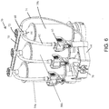
- the fluid injector 10 further has a multi-use disposable system (MUDS) 56 suitable for use over multiple injection protocols that is removably connectable with the fluid injector 10 .
- MUDS multi-use disposable system
- the MUDS 56 may be connected with the fluid injector 10 by a retaining mechanism 57 that engages a distal portion of the three syringes 58 of the MUDS 56 , to releasably secure the MUDS 56 within the injector 10 .
- Injector 10 and the corresponding MUDS 56 as illustrated in FIG. 5 are described in detail in WO 2016/112163 .
- the MUDS 56 may comprise one or more syringes or pumps 58 .
- the number of syringes 58 corresponds to the number of drive members/pistons on the fluid injector 10 .
- the MUDS 56 has three syringes 58 arranged in a side-by-side arrangement.
- Each syringe 58 has a bulk fluid connector 60 for connecting to a respective bulk fluid source (not shown) via a MUDS fluid path 62 .
- the MUDS fluid path 62 may be formed as a flexible tube that connects to the bulk fluid connector 60 having a spike element at its terminal end.
- the MUDS 56 has a frame 64 for supporting the one or more syringes 58a-58c .
- the syringes 58a-58c may be removably or non-removably connected to the frame 64 .
- Each syringe 58a-58c has an elongated, substantially cylindrical syringe body.
- Each syringe 58a-58c has a filling port 66 in fluid communication with the MUDS fluid path 62 for filling the syringe 58a-58c with fluid from a bulk fluid source.
- Each syringe 58a-58c further has a discharge outlet or conduit 68 at the terminal portion of its distal end.
- each syringe 58a-58c is in fluid communication with a manifold 70 .
- a valve 72 is associated with each discharge outlet 68 and is operable between a filling position, where the filling port 66 is in fluid communication with the syringe interior while the discharge outlet 68 is in fluid isolation from the syringe interior, and a delivery position, where the discharge outlet 68 is in fluid communication with the syringe interior while the filling port 66 is in fluid isolation from the syringe interior.
- the manifold 70 has a fluid pathway that is in fluid communication with each syringe 58a-58c and with a fluid outlet line 74 in fluid communication with a port 76 configured for connecting to a single use fluid path element (not shown) for delivering fluid to the patient.
- the motor 31 ( FIG. 2 ) provides the motive force to reciprocally drive the drive member/piston 19 in a distal direction and discharges fluid within the syringes 12, 34 or MUDS 56 .
- the motor 31 may have drive components, such as gears and shafts, that are operatively connected to the drive member/piston 19 to reciprocally move the drive member/piston 19 .
- Each motor 31 must be calibrated to correlate its operating characteristics, such as input current or output torque, to a flow rate or pressure and tolerances associated therewith.
- calibration may be desirable to compensate for any variations or out of specification behavior from any of the different components of the fluid injectors 10 , such as any variations in motor performance characteristics, particularly in fluid injectors with two or more syringes driven by two or more motors.
- conversion of motor input torque for one motor 31 to an injector output pressure may be different for another motor 31 .
- This variation may be further compounded by variations in tolerances of the drivetrain of the fluid injector 10 .
- the accuracy of flow rate or pressure in a fluid injector 10 is directly correlative to a system and method used to calibrate the motor 31 .
- FIG. 7 illustrates one example of an embodiment of a fluidless embodiment of pressure calibration system 80 (hereinafter referred to as "calibration system 80 ") of the present disclosure.
- the calibration system 80 is configured for connecting to one or more drive members 19 of a fluid injector 10 ( FIG. 8 ), such as any of the fluid injectors 10 shown in FIGS. 1 , 3 , and 5 , for performing a calibration routine to calibrate the pressure output of the individual motors and drive systems of the fluid injector 10 .
- calibration system 80 is illustrated as being configured to engage with a single drive member of a fluid injector, calibration systems including multiple housing set-ups for engaging with two, three, or all drive members of a specific fluid injector are envisioned and within the bounds of the present disclosure.
- the calibration system 80 disclosed herein avoids these limitations inherent in the prior art by eliminating the need for fluid in the calibration process while allowing for ready monitoring and calibration of a system without requiring a service technicians presence, allowing for early diagnosis of system issues, such as out of specification behavior of one or more injector components.
- the calibration system 80 has a housing 82 configured for connecting with the fluid injector 10 .
- the housing 82 is configured for connecting with the syringe port 13 of the fluid injector 10 (shown in FIG. 8 ) in a manner similar to the connection between the syringe 12 and the fluid injector 10 shown in FIGS. 1 , 3 , and 5 .
- the housing 82 has a proximal end 84 and a distal end 86 , with a sidewall extending therebetween along a length of a longitudinal axis 90 extending through a center of the housing 82 .
- the distal end 86 may have a conical shape that narrows in a distal direction, similar to the distal end of the syringe 12 .
- the distal end 86 may be configured for engaging the retaining mechanism 57 (see, e.g., FIG. 8 ).
- the proximal end 84 of the housing 82 may be sized and adapted for being removably inserted in or otherwise engaged with the syringe port 13 of the injector 10 (shown in FIGS. 1 , 3 , 5 , and 8 ).
- the proximal end 84 of the housing 82 defines an engagement section 92 that is configured to be removably inserted into (or otherwise engaged with) the syringe port 13 of the injector 10 while the remaining portion of the housing 82 remains outside of the syringe port 13 .
- the housing 82 may have one or more position markers 88 which may be used by an optical system (not shown) to determine a position of the drive member/piston 19 or piston engagement portion 96 , for example as the drive member/piston 19 or piston engagement portion 96 moves from a first, uncompressed positon to a second, at least partially compressed position.
- the drive system may determine the distance traveled by the drive member/piston 19 as it moves from the first, uncompressed positon to the second, at least partially compressed position, and deliver that distance information to a processor associated with the injector 10 , as described herein.
- the housing 82 includes a compressible member 94 having a drive member engagement portion 96 , and a sensor 100 , such as a force gauge.
- the compressible member 94 may include a one or more compressible springs 98 or other compressible components as described herein.
- the drive member engagement portion 96 is configured for contacting or connecting with the drive member 19 of the fluid injector 10 (shown in FIG. 8 ). In certain embodiments, the drive member engagement portion 96 may connect with the drive member 19 in a manner similar to the connection between the plunger 16 and the drive member 19 described herein with reference to FIGS. 1-2 .
- the drive member engagement portion 96 may have the same connection features as the plunger 16 to allow the compressible member 94 and sensor 100 to be connected to the drive member 19 such that the drive member engagement portion 96 and compressible member can be moved in a reciprocal manner within the housing 82 in a direction along the longitudinal axis 90 .
- the drive member 19 may abut and contact a proximal surface of the drive member engagement portion 96 , such that when a distal force is applied by the drive member 19 , the drive member engagement portion 96 is moved in the distal direction with concurrent compression of the compressible member 94 .
- the compressible member 94 such as the one or more compressible springe 98 may have a proximal end 102 connected with the drive member engagement portion 96 and a distal end 104 connected with a sensor 100 , such as a strain gauge, a force sensor, a load cell, a pressure sensor, a force transducer, and combination of any thereof.
- the compressible member 94 translates the force from the drive member 19 and motor 31 to the sensor 100 with a minimal loss of acoustic and/or frictional energy.
- the compressible member 94 is movable between a first, uncompressed position (shown in FIG.
- the compressible member 94 may be resilient, wherein the compressible member 94 reverts to the uncompressed position from the compressed position after the urging force imparted by the drive member 19 is removed, such as due to retraction of the drive member 19 .
- the compressible member 94 may be one or more mechanical springs.
- the compressible member 94 may be a spring, a plurality of springs, a pneumatic compression cell, a hydraulic compression cell, a compressible foam, an elastomer, a compressible rod, such as a rod made from a compressible elastomeric material, a material that changes at least one measurable property, for example electrical resistivity, when compressed, and combinations of any thereof.
- an incompressible engagement may be used between the drive member 19 and the sensor 100 such that the force translates directly from the drive member 19 to the sensor 100 and feeds back into the controller for calibration.
- the system may use motor current translation (PID) to determine pressure, which may vary with motor speed.
- PID motor current translation
- one or more of a strain gauge, a force sensor may be used to determine applied force.
- the compressible member 94 may provide sufficient stroke length for different motor speeds.
- the senor 100 is configured to measure the force that the drive member 19 and the motor 31 impart on the calibration system 80 .
- the sensor 100 may be a force gauge or a strain gauge.
- the sensor 100 may comprise a motor that pushes against the distal end 104 of the compressible member 94 based on the force imparted on the proximal end 102 of the compressible member 94 by the drive member 19 and the motor 31 .
- the senor 100 may be an optical force measurement system, wherein the sensor 100 is configured to measure movement of the compressible member 94 (or a portion of the force gauge 100 ) relative to the housing 82 as the drive member 19 compresses the compressible member 94 from the first, uncompressed position to the second, at least partially compressed position.
- the output from the sensor 100 may be sent to a processor, for example by a wired connection 95 or by wireless communication (e.g., WiFi, Bluetooth, or other wireless communication technology) such as a processor associated with the fluid injector 10 , an external processor, a hospital information system, or other processor, for a dynamic correlation of the measurement signal to pressure, for example using the modulus of compression for the compressible member 94 and an appropriate conversion algorithm, such as Hooke's Law for a compressible spring.
- the measurement signal of the sensor 100 may be a voltage signal that is sent a processor, described herein to be converted into a force measurement.
- a pressure calibration curve 106 ( FIG. 9 ) can be generated with real pressure values correlated to system readings for motor current.
- a three-dimensional surface profile ( FIG. 10 ) can be created to generate a calibration equation to be used for the drive member 19 and motor 31 combination.
- the drive member 19 may be driven distally such that the drive member 19 contacts or connects with the drive member engagement portion 96 of the calibration system 80 for the first, uncompressed position of the compressible member 96 .
- the compressible member 94 is compressed from the first, uncompressed position to a second, at least partially compressed position associated with the applied force by the drive member 19 on the compressible member 94 and the force imparted may be transferred to the sensor 100 .
- the sensor 100 may measure the force imparted by the drive member 19 and the motor 31 and send the measurement data to processor, such as described herein such that the input of the motor 31 can be adjusted based on a calibration curve 106 for each flow rate.
- the process can be repeated for various rates of movement of the drive member 19 that correspond to various flow rates to generate a three-dimensional calibration equation that calibrates the motor input/pressure output for various flow rates (see FIG. 10 ).
- the calibration curve may be utilized to adjust motor current or force such that multiple motors in a multi-fluid injector system may impart the accurate pressure to fluid within the syringe during an injection protocol.
- the calibration equation or calibration data may be used to monitor injector calibration and highlight trends over time, such as weakening of motor strength or other injector components so that such wear or defect may be corrected before failure. An analysis of accumulated or stored data based on the distance of motor travel relative to the force sensed by the calibration unit may provide an indication of some wear, potential failure, or failure.
- a calibration fixture 200 is shown in accordance with an example of the present disclosure.
- the calibration fixture 200 can be used to test a drive mechanism 202 of an injector separately from the injector.
- the calibration fixture 200 is configured for calibrating the pressure output of the drive mechanism 202 that is removable from the injector (not shown). In this manner, the calibration fixture 200 can be used to test a variety of different drive mechanisms 202 configured for use with a variety of different injectors separate from the injectors themselves.
- the drive mechanism 202 may comprise a motor 31 and a drive member 19 , such as a piston.
- the calibration fixture 200 has a mounting platform 204 for mounting the drive mechanism 202 .
- the mounting platform 204 has an opening (not shown) for receiving at least a portion of the drive mechanism 202 , such as the piston 19 .
- the drive mechanism 202 may be fixedly mounted to the mounting platform 204 while the piston 19 extends through the opening to engage a force sensor 212 .
- the calibration fixture 200 may have a piston engagement portion 208 , a compressible member 210 , and a force gauge 212 .
- the piston engagement portion 208 is configured for contacting or connecting with the piston 19 .
- the compressible member 210 which may be any of the compressible members described herein, translates the force from the drive member 19 and motor 31 to a sensor 212 , such as a force gauge, a strain gauge, a force sensor, a load cell, a pressure sensor, a force transducer, and combination of any thereof.
- the compressible member 210 is movable between a first, uncompressed position and a second, at least partially compressed position due to the urging force imparted by the drive member 19 driven by the motor 31 . Compression of the compressible member 210 between the uncompressed position and the at least partially compressed position allows the drive member 19 to move in the same manner as during delivery of fluid from a syringe 12 .
- the compressible member 210 may be compressed by the drive member 19 at a varying force over time (see, FIG. 12 ) to simulate different flow rates.
- the compressible member 210 may be resilient, wherein the compressible member 210 reverts to the first, uncompressed position from the compressed second, at least partially position after the urging force imparted by the drive member 19 is removed, such as due to retraction of the drive member 19 .
- the compressible member 210 may be a mechanical spring.
- the compressible member 210 has sufficient length to be compressed over the entire stroke of the drive member 19 .
- the senor 212 may be configured to measure the force that the drive member 19 and the motor 31 impart on the calibration fixture 200 .
- a plurality of sensors 212 may be used to provide redundant readings.
- the motor output, as measured by the sensor 212 can be correlated to a pressure value that would be generated if the drive member 19 was driving a fluid-filled syringe in a manner similar described herein with reference to FIG. 10 .
- the drive mechanism 202 can be pressure calibrated independently of the injector. In this manner, a defective drive mechanism 202 may be replaced with a new drive mechanism 202 that has been calibrated without causing any additional downtime to the injector due to further pressure calibration of a new drive mechanism.
Landscapes
- Health & Medical Sciences (AREA)
- Engineering & Computer Science (AREA)
- Heart & Thoracic Surgery (AREA)
- Animal Behavior & Ethology (AREA)
- Vascular Medicine (AREA)
- Veterinary Medicine (AREA)
- Anesthesiology (AREA)
- Biomedical Technology (AREA)
- Public Health (AREA)
- Hematology (AREA)
- Life Sciences & Earth Sciences (AREA)
- General Health & Medical Sciences (AREA)
- General Engineering & Computer Science (AREA)
- General Physics & Mathematics (AREA)
- Physics & Mathematics (AREA)
- Automation & Control Theory (AREA)
- Mechanical Engineering (AREA)
- Fluid Mechanics (AREA)
- Infusion, Injection, And Reservoir Apparatuses (AREA)
Claims (14)
- Système d'étalonnage (80) pour étalonner une sortie de pression d'un organe d'entraînement d'un injecteur de fluide (10), le système d'étalonnage (80) comprenant :un boîtier (82) conçu pour se raccorder à l'injecteur de fluide (10) ;une partie de prise d'organe d'entraînement (96) conçue pour entrer en contact avec un organe d'entraînement (19) de l'injecteur de fluide (10) ;un capteur (100) relié à l'organe compressible (94),caractérisé en ce que le système d'étalonnage (80) comprend en outreun organe compressible (94) relié à son extrémité proximale à la partie de prise d'organe d'entraînement (96), dans lequel l'organe compressible (94) est compressé avec le déplacement de l'organe d'entraînement (19) de l'injecteur de fluide (10) entre une première position décompressée et une seconde position au moins en partie compressée de l'injecteur de fluide (10) dans une direction distale ;dans lequel le capteur (100) est conçu pour mesurer une force appliquée par l'organe d'entraînement (19) lorsque l'organe compressible (94) est dans la seconde position au moins en partie compressée.
- Système d'étalonnage (80) selon la revendication 1, dans lequel le capteur (100) est sélectionné parmi le groupe constitué d'un extensomètre, d'un capteur de force, d'un dynamomètre de pression, d'un capteur de pression, d'un transducteur de force et d'une combinaison de ceux-ci.
- Système d'étalonnage (80) selon la revendication 2, dans lequel le capteur (100) comprend un extensomètre ou un capteur de force.
- Système d'étalonnage (80) selon l'une quelconque des revendications 1 à 3, dans lequel l'organe compressible (94) est sélectionné parmi le groupe constitué d'un ressort (98), d'une pluralité de ressorts, d'une cellule à compression pneumatique, d'une cellule à compression hydraulique, d'une mousse compressible, d'un élastomère et de combinaisons de ceux-ci, de préférence dans lequel l'organe compressible est un ressort (98).
- Système d'étalonnage (80) selon l'une quelconque des revendications 1 à 4, dans lequel le capteur (100) est en communication filaire (95) ou en communication sans fil avec un processeur et une sortie du capteur (100) est transmise au processeur.
- Système d'étalonnage (80) selon l'une quelconque des revendications 1 à 5, dans lequel une sortie du capteur (10) est utilisée pour étalonner une entrée sur un ou plusieurs d'un moteur (31), de l'organe d'entraînement (19), d'une vis sphérique en communication mécanique avec le moteur (31) et l'organe d'entraînement (19), d'un composant de friction d'un réservoir de distribution de fluide jetable, et d'autres composants mécaniques compressibles.
- Système d'étalonnage (80) selon l'une quelconque des revendications 1 à 6, dans lequel une sortie du capteur (100) est utilisée pour générer une courbe d'étalonnage (106) pour étalonner une sortie de pression de l'organe d'entraînement (19) de l'injecteur de fluide (10).
- Système d'étalonnage (80) selon la revendication 7, dans lequel la courbe d'étalonnage (106) est utilisée pour déterminer ou prédire un état défectueux.
- Système d'étalonnage (80) selon la revendication 1,
dans lequel l'organe compressible (94) a un module de compression connu ; et
dans lequel le capteur (100) est configuré pour mesurer un déplacement de l'organe d'entraînement (19) lorsque l'organe compressible (94) est dans la seconde position au moins en partie compressée. - Système d'étalonnage (80) selon la revendication 9, dans lequel l'organe compressible (94) est un ressort (98).
- Système d'étalonnage (80) selon l'une quelconque des revendications 9 ou 10, dans lequel le capteur (100) est en communication filaire (95) ou sans fil avec un processeur et une sortie du capteur (100) est transmise au processeur.
- Système d'étalonnage (80) selon la revendication 11, dans lequel le processeur détermine la sortie de pression de l'injecteur de fluide (10) à partir de la sortie du capteur (100) et du module de compression de l'organe compressible (94).
- Système d'étalonnage (80) selon l'une quelconque des revendications 9 à 12, dans lequel une sortie du capteur (100) est utilisée pour générer une courbe d'étalonnage (106) pour étalonner la sortie de pression d'un organe d'entraînement (19) de l'injecteur de fluide (10).
- Système d'étalonnage (80) selon la revendication 13, dans lequel la courbe d'étalonnage (106) est utilisée pour déterminer un état défectueux.
Applications Claiming Priority (2)
| Application Number | Priority Date | Filing Date | Title |
|---|---|---|---|
| US201762552428P | 2017-08-31 | 2017-08-31 | |
| PCT/US2018/048313 WO2019046282A1 (fr) | 2017-08-31 | 2018-08-28 | Système et procédé d'étalonnage de pression d'injecteur |
Publications (2)
| Publication Number | Publication Date |
|---|---|
| EP3675931A1 EP3675931A1 (fr) | 2020-07-08 |
| EP3675931B1 true EP3675931B1 (fr) | 2021-08-11 |
Family
ID=63528965
Family Applications (1)
| Application Number | Title | Priority Date | Filing Date |
|---|---|---|---|
| EP18766499.0A Active EP3675931B1 (fr) | 2017-08-31 | 2018-08-28 | Système et procédé d'étalonnage de pression d'injecteur |
Country Status (6)
| Country | Link |
|---|---|
| US (1) | US11598664B2 (fr) |
| EP (1) | EP3675931B1 (fr) |
| JP (1) | JP7221885B2 (fr) |
| AU (1) | AU2018326485B2 (fr) |
| CA (1) | CA3067625C (fr) |
| WO (1) | WO2019046282A1 (fr) |
Families Citing this family (3)
| Publication number | Priority date | Publication date | Assignee | Title |
|---|---|---|---|---|
| CN109959434B (zh) * | 2019-04-19 | 2020-07-31 | 合肥工业大学 | 一种基于相频特性的钠流量计在线校准方法 |
| US20220375586A1 (en) * | 2019-11-21 | 2022-11-24 | Bayer Healthcare Llc | System, method, and computer program product for smart fluid injector performance monitoring |
| AU2021264011A1 (en) | 2020-04-30 | 2022-11-10 | Bayer Healthcare Llc | System, device, and method for safeguarding wellbeing of patients for fluid injection |
Family Cites Families (525)
| Publication number | Priority date | Publication date | Assignee | Title |
|---|---|---|---|---|
| US383858A (en) | 1888-06-05 | mepartland | ||
| US508584A (en) | 1893-11-14 | Device for mixing hot and gold water for bathing | ||
| US945143A (en) | 1909-07-28 | 1910-01-04 | Iacques Szamek | Apparatus for mixing liquids. |
| US1020166A (en) | 1911-09-06 | 1912-03-12 | Frederick Merrill Tibbott | Rail-joint. |
| GB201800A (en) | 1922-09-18 | 1923-08-09 | Robert Sowter Hubbard | An improved toy |
| US2511291A (en) | 1947-03-12 | 1950-06-13 | Grover C Mueller | Mixer for liquids |
| US2583206A (en) | 1949-12-01 | 1952-01-22 | Separator Ab | Apparatus for homogenizing |
| US3156236A (en) | 1961-12-07 | 1964-11-10 | Cordis Corp | Medical injector |
| US3159312A (en) | 1962-09-28 | 1964-12-01 | Budd Co | Dispensing device for mixing two viscous fluids |
| US3276472A (en) | 1963-12-03 | 1966-10-04 | Medex Inc | Medical valve |
| DE1220394B (de) | 1964-09-12 | 1966-07-07 | Glanzstoff Koeln Ges Mit Besch | Vorrichtung zum kontinuierlichen Mischen und Homogenisieren von Fluessigkeiten verschiedener Viskositaet |
| CH456051A (de) | 1966-06-30 | 1968-05-15 | Contraves Ag | Medizinisches Kontrastmittel-Einspritzgerät |
| US3623474A (en) | 1966-07-25 | 1971-11-30 | Medrad Inc | Angiographic injection equipment |
| US3520295A (en) | 1968-03-06 | 1970-07-14 | Gen Electric | Cardiac r-wave detector with automatic gain control |
| BE758739A (fr) | 1969-11-13 | 1971-04-16 | Fuji Photo Film Co Ltd | Procede et appareil en vue de transporter un fluide |
| US3635444A (en) | 1970-09-08 | 1972-01-18 | Amvit | Static mixer |
| US3701345A (en) | 1970-09-29 | 1972-10-31 | Medrad Inc | Angiographic injector equipment |
| US3671208A (en) | 1970-10-09 | 1972-06-20 | Wayne G Medsker | Fluid mixing apparatus |
| US3793600A (en) | 1971-03-16 | 1974-02-19 | Strategic Automated Systems In | Record medium with validating and cancelling feature and method |
| NL171912C (nl) | 1971-04-13 | 1983-06-01 | Electricity Council | Werkwijze voor het vervaardigen van ijzerfoelie. |
| US4001549A (en) | 1971-06-10 | 1977-01-04 | Corwin Edward J | Marking document and template assembly and method of making the assembly |
| US3927955A (en) | 1971-08-23 | 1975-12-23 | East West Medical Products Inc | Medical cassette pump |
| US3755655A (en) | 1971-10-26 | 1973-08-28 | Tac Ind Inc | Machine processed data card |
| US3839708A (en) | 1972-06-28 | 1974-10-01 | Searle Medidata Inc | Input-output terminal for hospital information system |
| US3868967A (en) | 1973-02-16 | 1975-03-04 | Shropshire Kenneth W | Adapter for mixing fluids |
| US3812843A (en) | 1973-03-12 | 1974-05-28 | Lear Siegler Inc | Method and apparatus for injecting contrast media into the vascular system |
| JPS5011296A (fr) | 1973-05-31 | 1975-02-05 | ||
| JPS5418908B2 (fr) | 1973-06-15 | 1979-07-11 | ||
| US3895220A (en) | 1973-09-07 | 1975-07-15 | Docutronix Inc | Selectively encodable envelope insert and related apparatus |
| US3898983A (en) | 1973-10-03 | 1975-08-12 | James O Elam | Device and method for detecting the degree of muscle relaxation of a medical patient |
| US3968195A (en) | 1974-06-17 | 1976-07-06 | Marilyn Bishop | Method for making sterile connections |
| US3888239A (en) | 1974-06-21 | 1975-06-10 | Morton K Rubinstein | Fluid injection system |
| US4038981A (en) | 1974-07-26 | 1977-08-02 | Burron Medical Products, Inc. | Electronically controlled intravenous infusion set |
| US3941126A (en) | 1974-08-08 | 1976-03-02 | Dietrich Joseph W | Apparatus for long term intravenous administration of diluted incompatible multiple medications |
| US4006736A (en) | 1974-11-27 | 1977-02-08 | Medrad, Inc. | Angiographic injector |
| US3995381A (en) | 1975-06-27 | 1976-12-07 | Ken Max Manfred | Low visibility answer sheet and method of testing |
| JPS5226193A (en) | 1975-08-22 | 1977-02-26 | Houseikai | Remote control barium injector |
| US4044757A (en) | 1976-01-14 | 1977-08-30 | The Kendall Company | Cholangiography device and method |
| US4273122A (en) | 1976-11-12 | 1981-06-16 | Whitney Douglass G | Self contained powered injection system |
| US4135247A (en) | 1977-08-15 | 1979-01-16 | Siemens Aktiengesellschaft | Tomography signal processing system |
| US4284073A (en) | 1977-10-11 | 1981-08-18 | Krause Horst E | Method and apparatus for pumping blood within a vessel |
| US4191183A (en) | 1977-10-31 | 1980-03-04 | Barry Mendelson | Mixing chamber for use in plural medical liquid intravenous administration set |
| US4151845A (en) | 1977-11-25 | 1979-05-01 | Miles Laboratories, Inc. | Blood glucose control apparatus |
| US4187057A (en) | 1978-01-11 | 1980-02-05 | Stewart-Naumann Laboratories, Inc. | Peristaltic infusion pump and disposable cassette for use therewith |
| US4262824A (en) | 1978-02-17 | 1981-04-21 | Baxter Travenol Laboratories, Inc. | Low-current E-frame electronic magnet with a permanent magnet armature for an I. V. valving controller |
| US4263916A (en) | 1978-03-27 | 1981-04-28 | University Of Southern California | Image averaging for angiography by registration and combination of serial images |
| US4448200A (en) | 1978-03-27 | 1984-05-15 | University Of Southern California | System and method for dynamic background subtraction |
| US4329067A (en) | 1978-04-19 | 1982-05-11 | Bruce J. Landis | Fluid mixer |
| US4207871A (en) | 1978-06-07 | 1980-06-17 | Imed Corporation | System for controlling the flow of intravenous fluids to a patient |
| US4199000A (en) | 1978-07-19 | 1980-04-22 | Edstrom William E | Cross-contamination isolator |
| US4223675A (en) | 1978-07-24 | 1980-09-23 | Baxter Travenol Laboratories, Inc. | Solution containers such as blood bags and system for preparing same |
| US4204775A (en) | 1978-08-08 | 1980-05-27 | General Dynamics Corporation Pomona Division | Mixing device for simultaneously dispensing two-part liquid compounds from packaging kit |
| US4208136A (en) | 1978-12-01 | 1980-06-17 | Komax Systems, Inc. | Static mixing apparatus |
| EP0089404A1 (fr) | 1979-02-28 | 1983-09-28 | Abbott Laboratories | Système d'écoulement par gravité pour administrer successivement plusieurs liquides médicaux |
| US4280494A (en) | 1979-06-26 | 1981-07-28 | Cosgrove Robert J Jun | System for automatic feedback-controlled administration of drugs |
| US4315247A (en) | 1979-08-13 | 1982-02-09 | Germanton Charles E | Security systems employing an electronic lock and key apparatus |
| US4319568A (en) | 1979-10-29 | 1982-03-16 | Vickers Limited | Liquid dispensing apparatus |
| CA1171030A (fr) | 1979-11-05 | 1984-07-17 | David Bellamy | Dispositif de transfert de fluides |
| JPS5675131A (en) | 1979-11-22 | 1981-06-22 | Olympus Optical Co | Endoscope apparatus |
| US4341153A (en) | 1980-01-08 | 1982-07-27 | Truswal Systems Corp. | Splicing and truss assembly apparatus and methods |
| FR2493708A1 (fr) | 1980-11-07 | 1982-05-14 | Mecaserto | Appareil de preparation d'un produit de traitement destine a etre injecte dans l'organisme d'un patient |
| US4340153A (en) | 1980-11-28 | 1982-07-20 | Spivey David L | Method and apparatus for medication dispensing |
| US4396385A (en) | 1980-12-05 | 1983-08-02 | Baxter Travenol Laboratories, Inc. | Flow metering apparatus for a fluid infusion system |
| US4409966A (en) | 1981-05-29 | 1983-10-18 | Lambrecht Richard M | Method and apparatus for injecting a substance into the bloodstream of a subject |
| JPS5815842A (ja) | 1981-07-20 | 1983-01-29 | 株式会社東芝 | 画像輪郭抽出装置 |
| US4392849A (en) | 1981-07-27 | 1983-07-12 | The Cleveland Clinic Foundation | Infusion pump controller |
| US4447230A (en) | 1981-08-05 | 1984-05-08 | Quest Medical, Inc. | Intravenous administration set assembly |
| US4444198A (en) | 1981-12-21 | 1984-04-24 | Petre John H | Circulatory monitoring system and method |
| DE3203594A1 (de) | 1982-02-03 | 1983-08-11 | Siemens AG, 1000 Berlin und 8000 München | Roentgendiagnostikanlage fuer angiographische roentgenaufnahmen |
| JPS58152542A (ja) | 1982-03-05 | 1983-09-10 | 株式会社東芝 | X線診断装置 |
| US4504908A (en) | 1982-03-15 | 1985-03-12 | General Electric Company | Matched filter for X-ray temporal subtraction |
| US4434820A (en) | 1982-05-05 | 1984-03-06 | Glass John P | Syringe loader and method |
| US4823833A (en) | 1982-06-24 | 1989-04-25 | Baxter Healthcare Corporation | Fluid communication device |
| US4515584A (en) | 1982-07-06 | 1985-05-07 | Fujisawa Pharmaceutical Co., Ltd. | Artificial pancreas |
| US4441823A (en) | 1982-07-19 | 1984-04-10 | Power Harold H | Static line mixer |
| US4474476A (en) | 1982-08-05 | 1984-10-02 | Jack Thomsen | Chemical printing liquid method and system |
| US4512764A (en) | 1982-09-27 | 1985-04-23 | Wunsch Richard E | Manifold for controlling administration of multiple intravenous solutions and medications |
| US4542459A (en) | 1982-11-26 | 1985-09-17 | General Electric Company | Matched filter for x-ray hybrid subtraction |
| US4655197A (en) | 1982-12-01 | 1987-04-07 | Snyder Laboratories, Inc. | Lavage system with variable frequency, flow rate and pressure |
| US4479760A (en) | 1982-12-28 | 1984-10-30 | Baxter Travenol Laboratories, Inc. | Actuator apparatus for a prepackaged fluid processing module having pump and valve elements operable in response to applied pressures |
| US4479761A (en) | 1982-12-28 | 1984-10-30 | Baxter Travenol Laboratories, Inc. | Actuator apparatus for a prepackaged fluid processing module having pump and valve elements operable in response to externally applied pressures |
| US4479762A (en) | 1982-12-28 | 1984-10-30 | Baxter Travenol Laboratories, Inc. | Prepackaged fluid processing module having pump and valve elements operable in response to applied pressures |
| US4509526A (en) | 1983-02-08 | 1985-04-09 | Lawrence Medical Systems, Inc. | Method and system for non-invasive ultrasound Doppler cardiac output measurement |
| US4585009A (en) | 1983-02-28 | 1986-04-29 | E. R. Squibb & Sons, Inc. | Strontium-rubidium infusion pump with in-line dosimetry |
| JPS59160431A (ja) | 1983-03-01 | 1984-09-11 | オリンパス光学工業株式会社 | 内視鏡の送気送液装置 |
| JPS59180452A (ja) | 1983-03-31 | 1984-10-13 | Toshiba Corp | パルスx線診断装置 |
| US4625494A (en) | 1983-04-28 | 1986-12-02 | Pfrimmer & Co. Pharmazeutische Werke Erlangen | Method and apparatus for making mixtures of pharmaceutical liquids |
| JPS59214431A (ja) | 1983-05-20 | 1984-12-04 | 株式会社東芝 | 放射線診断装置 |
| JPS59214432A (ja) | 1983-05-20 | 1984-12-04 | 株式会社東芝 | 放射線診断装置 |
| US4610670A (en) | 1983-06-13 | 1986-09-09 | E. I. Du Pont De Nemours And Company | Sterile connection process, apparatus and system |
| JPS607292A (ja) | 1983-06-27 | 1985-01-16 | Toshiba Corp | 立体x線テレビ装置 |
| GB8318670D0 (en) | 1983-07-11 | 1983-08-10 | Ici Plc | Fluid delivery apparatus |
| DE3329977C2 (de) | 1983-08-19 | 1985-10-17 | B. Braun Melsungen Ag, 3508 Melsungen | Vorrichtung zur dosierten gleichzeitigen Infusion von Lösungen |
| DE3433207A1 (de) | 1983-09-09 | 1985-04-18 | Nippon Gakki Seizo K.K., Hamamatsu, Shizuoka | Resonanzboden fuer musikinstrumente |
| US4798590A (en) | 1983-11-22 | 1989-01-17 | Medical Technology Products, Inc. | Intravenous infusion pumping system including independent pump set |
| JPS60114987A (ja) | 1983-11-25 | 1985-06-21 | 株式会社東芝 | 料金収受装置 |
| US4559036A (en) | 1983-12-14 | 1985-12-17 | Wunsch Richard E | Apparatus for controlling administration of multiple intravenous solutions and medications |
| US4563175A (en) | 1983-12-19 | 1986-01-07 | Lafond Margaret | Multiple syringe pump |
| NL8304397A (nl) | 1983-12-22 | 1985-07-16 | Philips Nv | Roentgenonderzoekapparaat met beeldsubstractie. |
| JPS60150729A (ja) | 1984-01-19 | 1985-08-08 | 株式会社東芝 | X線診断装置 |
| US4854324A (en) | 1984-01-31 | 1989-08-08 | Medrad, Inc. | Processor-controlled angiographic injector device |
| US5100380A (en) | 1984-02-08 | 1992-03-31 | Abbott Laboratories | Remotely programmable infusion system |
| US4610790A (en) | 1984-02-10 | 1986-09-09 | Sterimatics Company Limited Partnership | Process and system for producing sterile water and sterile aqueous solutions |
| JPS60194935A (ja) | 1984-03-19 | 1985-10-03 | 株式会社日立メデイコ | X線血管像透視撮影装置 |
| JPS60194934A (ja) | 1984-03-19 | 1985-10-03 | 株式会社日立メデイコ | X線血管像透視撮影装置 |
| CH663739A5 (de) | 1984-03-21 | 1988-01-15 | Urma Werkzeug Maschf | Vorrichtung an einem durchmesserverstellbaren ausdrehwerkzeug mit schneidplattenhalter. |
| FR2561949B1 (fr) | 1984-03-29 | 1991-05-03 | Arc Services | Systeme de transport de colis |
| US4572724A (en) | 1984-04-12 | 1986-02-25 | Pall Corporation | Blood filter |
| US4551133A (en) | 1984-04-16 | 1985-11-05 | American Hospital Supply Corporation | Patient controlled medication infusion system |
| JPS60253197A (ja) | 1984-05-29 | 1985-12-13 | Toshiba Corp | X線診断装置 |
| JPH0614746B2 (ja) | 1984-09-13 | 1994-02-23 | 株式会社東芝 | X線画像処理装置 |
| JPS61115539A (ja) | 1984-11-09 | 1986-06-03 | 株式会社 日立メデイコ | デイジタル型x線撮影装置 |
| US4634426A (en) | 1984-12-11 | 1987-01-06 | Baxter Travenol Laboratories | Medical infusion controller and user interface |
| US4676776A (en) | 1985-01-18 | 1987-06-30 | Intelligent Medicine, Inc. | Device and method for effecting application of a therapeutic agent |
| US5088981A (en) | 1985-01-18 | 1992-02-18 | Howson David C | Safety enhanced device and method for effecting application of a therapeutic agent |
| DE3575862D1 (de) | 1985-02-18 | 1990-03-15 | Medrad Inc | Angiographischer injektor mit einer steuereinheit. |
| JPS61220628A (ja) | 1985-03-28 | 1986-09-30 | 株式会社 日立メデイコ | X線動態像計測装置 |
| DE8516350U1 (fr) | 1985-06-04 | 1988-10-27 | Baxter Travenol Laboratories, Inc., Deerfield, Ill., Us | |
| US4935005A (en) | 1985-06-05 | 1990-06-19 | Nestle, S.A. | Opthalmic fluid flow control system |
| DE3687794T2 (de) | 1985-08-06 | 1993-09-23 | Baxter Int | Vom patienten kontrollierte verabreichung von heilmitteln. |
| US4710166A (en) | 1985-11-08 | 1987-12-01 | Quest Medical, Inc. | Automated drug additive infusion system |
| JPS62216199A (ja) | 1986-03-18 | 1987-09-22 | Toshiba Corp | X線ct装置 |
| JPH0672866B2 (ja) | 1986-03-19 | 1994-09-14 | 本田技研工業株式会社 | 酸素濃度検出装置 |
| JPH072182B2 (ja) | 1986-04-07 | 1995-01-18 | テルモ株式会社 | 輸液ポンプ |
| FR2598583A1 (fr) | 1986-05-06 | 1987-11-13 | Thomson Cgr | Installation de radiologie a reseau de communication |
| US4750643A (en) | 1986-08-04 | 1988-06-14 | Sugrin Surgical Instrumentation, Inc. | Sterile fluid dispensing system and method |
| JPS6340538A (ja) | 1986-08-06 | 1988-02-20 | 株式会社東芝 | Ct画像診断方法 |
| US4754786A (en) | 1986-09-05 | 1988-07-05 | Roderick Roberts | Sterile fluid storage and dispensing apparatus and method for filling same |
| US4781687A (en) | 1986-10-16 | 1988-11-01 | Baxter Travenol Laboratories, Inc. | Irrigation system utilizing air bladder pressure regulator and method of use |
| US4854301A (en) | 1986-11-13 | 1989-08-08 | Olympus Optical Co., Ltd. | Endoscope apparatus having a chair with a switch |
| US4936832A (en) | 1986-11-24 | 1990-06-26 | Vaillancourt Vincent L | Ambulatory disposable infusion delivery system |
| US4793357A (en) | 1986-11-24 | 1988-12-27 | Picker International, Inc. | CT blood flow mapping with xenon gas enhancement |
| US4789014A (en) | 1986-12-05 | 1988-12-06 | Baxter International Inc. | Automated system for adding multiple fluids to a single container |
| US5056568A (en) | 1986-12-05 | 1991-10-15 | Clintec Nutrition Company | Automated system for adding multiple fluids to a single container |
| JPS63164931A (ja) | 1986-12-27 | 1988-07-08 | 株式会社東芝 | 内視鏡の定圧装置 |
| SE457056B (sv) | 1987-01-29 | 1988-11-28 | Gambro Ab | System foer beredning av en vaetska avsedd foer en medicinsk behandling |
| JP2602823B2 (ja) | 1987-03-11 | 1997-04-23 | 株式会社東芝 | 内視鏡の送液送気装置 |
| US4976687A (en) | 1987-05-11 | 1990-12-11 | James Martin | Apparatus for controlling the supplying of intravenous fluids |
| JPS63290547A (ja) | 1987-05-25 | 1988-11-28 | Hitachi Medical Corp | テレビ断層撮影装置 |
| US4887554A (en) | 1987-05-27 | 1989-12-19 | Whitford Darryl R | Animal drench |
| US4838856A (en) | 1987-07-02 | 1989-06-13 | Truckee Meadows Research & Development | Fluid infusion flow control system |
| US5207642A (en) | 1987-08-07 | 1993-05-04 | Baxter International Inc. | Closed multi-fluid delivery system and method |
| US4925444A (en) | 1987-08-07 | 1990-05-15 | Baxter Travenol Laboratories, Inc. | Closed multi-fluid delivery system and method |
| DE3826550C2 (de) | 1987-08-07 | 1994-01-13 | Toshiba Kawasaki Kk | Einrichtung zum Darstellen von Röntgenbildern |
| DE3726452A1 (de) | 1987-08-08 | 1989-02-16 | Schael Wilfried | Schlauchpumpe fuer medizinische zwecke |
| US4880014A (en) | 1987-08-14 | 1989-11-14 | Zarowitz Barbara J | Method for determining therapeutic drug dosage using bioelectrical resistance and reactance measurements |
| US4795429A (en) | 1987-10-28 | 1989-01-03 | Feldstein Marvin A | Method and apparatus for use in the control of intravenous medication introduction |
| US6796296B2 (en) | 2002-06-05 | 2004-09-28 | Jay S. Kim | Fluid swirling device for an internal combustion engine |
| US4835521A (en) | 1987-11-05 | 1989-05-30 | Emhart Industries, Inc. | Fluid status detector |
| DE3739229A1 (de) | 1987-11-19 | 1989-06-01 | Siemens Ag | Medizinische untersuchungsanlage |
| DE3739230A1 (de) | 1987-11-19 | 1989-06-01 | Siemens Ag | Medizinische untersuchungsanlage |
| US5040537A (en) | 1987-11-24 | 1991-08-20 | Hitachi, Ltd. | Method and apparatus for the measurement and medical treatment using an ultrasonic wave |
| US4863425A (en) | 1987-12-04 | 1989-09-05 | Pacesetter Infusion, Ltd. | Patient-side occlusion detection system for a medication infusion system |
| US4874359A (en) | 1987-12-14 | 1989-10-17 | White Frederick R | Power infuser |
| US4887208A (en) | 1987-12-18 | 1989-12-12 | Schneider Bruce H | Sales and inventory control system |
| US4853521A (en) | 1987-12-28 | 1989-08-01 | Claeys Ronald W | System for verifying and recording drug administration to a patient |
| US5053002A (en) | 1988-01-11 | 1991-10-01 | Olympus Corporation | Irrigation system for angioscope |
| JP2627294B2 (ja) | 1988-02-13 | 1997-07-02 | 株式会社日立メディコ | 造影剤濃度調節機能付ct装置 |
| US5108363A (en) | 1988-02-19 | 1992-04-28 | Gensia Pharmaceuticals, Inc. | Diagnosis, evaluation and treatment of coronary artery disease by exercise simulation using closed loop drug delivery of an exercise simulating agent beta agonist |
| US5123121A (en) | 1988-03-07 | 1992-06-23 | Bell Helmets, Inc. | Helmet retention system with adjustable buckle |
| GB8808305D0 (en) | 1988-04-08 | 1988-05-11 | Nycomed As | Compositions |
| DE3812584A1 (de) | 1988-04-13 | 1989-10-26 | Mic Medical Instr Corp | Vorrichtung zur biofeedbackkontrolle von koerperfunktionen |
| US4901731A (en) | 1988-04-27 | 1990-02-20 | Millar Instruments, Inc. | Single sensor pressure differential device |
| US4943779A (en) | 1988-05-19 | 1990-07-24 | Worcester Polytechnic Institute | Digital sweep generator |
| DE3817411A1 (de) | 1988-05-21 | 1989-11-30 | Fresenius Ag | Mehrfachinfusionssystem |
| US4857056A (en) | 1988-07-06 | 1989-08-15 | Sherwood Medical Company | Auto-flush syringe pump |
| US4950245A (en) | 1988-07-08 | 1990-08-21 | I-Flow Corporation | Multiple fluid cartridge and pump |
| US4954129A (en) | 1988-07-25 | 1990-09-04 | Abbott Laboratories | Hydrodynamic clot flushing |
| US5021046A (en) | 1988-08-10 | 1991-06-04 | Utah Medical Products, Inc. | Medical pressure sensing and display system |
| US4946439A (en) | 1988-08-15 | 1990-08-07 | Critikon, Inc. | Dual source parenteral infusion system with secondary infusion module |
| GB8822708D0 (en) | 1988-09-28 | 1988-11-02 | Core Consulting Group | Improved microwave-powered heating device |
| US4943279A (en) | 1988-09-30 | 1990-07-24 | C. R. Bard, Inc. | Medical pump with infusion controlled by a detachable coded label |
| JPH02109546A (ja) | 1988-10-18 | 1990-04-23 | Toshiba Corp | X線ct装置を用いた診断装置 |
| US5276614A (en) | 1989-11-17 | 1994-01-04 | Picker International, Inc. | Dynamic bandwidth reconstruction |
| US4965726A (en) | 1988-10-20 | 1990-10-23 | Picker International, Inc. | CT scanner with segmented detector array |
| US5228070A (en) | 1988-10-20 | 1993-07-13 | Picker International, Inc. | Constant image quality CT scanner with variable radiation flux density |
| US5262946A (en) | 1988-10-20 | 1993-11-16 | Picker International, Inc. | Dynamic volume scanning for CT scanners |
| US4947412A (en) | 1988-10-20 | 1990-08-07 | Picker International, Inc. | X-ray detector for CT scanners |
| US5166961A (en) | 1988-10-20 | 1992-11-24 | Picker International, Inc. | CT scanner having multiple detector widths |
| US5069662A (en) | 1988-10-21 | 1991-12-03 | Delcath Systems, Inc. | Cancer treatment |
| US4929818A (en) | 1988-11-15 | 1990-05-29 | Rainbarrel Corporation | Method and apparatus for vending a containerized product on multiple occasions following at least one refill of the container with the product |
| EP0378896A3 (fr) | 1988-11-23 | 1991-05-22 | Picker International, Inc. | Détecteurs de rayonnement |
| JP2781914B2 (ja) | 1988-12-09 | 1998-07-30 | 日本アイデント・グラフ株式会社 | 連続立体撮影観察装置 |
| US4946256A (en) | 1989-01-11 | 1990-08-07 | Nm Laser Products, Inc. | Right angle shutter for laser beam |
| US4879880A (en) | 1989-01-17 | 1989-11-14 | Frank Harrison | Air temperature regulator |
| US5153827A (en) | 1989-01-30 | 1992-10-06 | Omni-Flow, Inc. | An infusion management and pumping system having an alarm handling system |
| JP2849396B2 (ja) | 1989-02-28 | 1999-01-20 | 株式会社日立メディコ | X線ct造影撮影システム |
| JPH02234747A (ja) | 1989-03-09 | 1990-09-17 | Toshiba Corp | 同期画像撮影装置 |
| US5009654A (en) | 1989-03-10 | 1991-04-23 | Baxter International Inc. | Sterile product and method for sterilizing and assembling such product |
| US4952068A (en) | 1989-03-21 | 1990-08-28 | Flint Theodore R | Static mixing device and container |
| US5113905A (en) | 1989-03-27 | 1992-05-19 | Michael D. Hoyle | Carbon dioxide fill manifold and method |
| JPH0412994Y2 (fr) | 1989-04-04 | 1992-03-27 | ||
| JPH0355040A (ja) | 1989-07-21 | 1991-03-08 | Shimadzu Corp | X線回転式ステレオ・ディジタル・サブトラクション装置 |
| EP1327454A3 (fr) | 1989-08-02 | 2003-12-03 | Mitra Medical Technology AB | Méthode de traitement à l'aide de médicaments |
| US5010473A (en) | 1989-08-31 | 1991-04-23 | Duke University | Method and apparatus for model-based control of an open-loop process |
| US4978335A (en) | 1989-09-29 | 1990-12-18 | Medex, Inc. | Infusion pump with bar code input to computer |
| US5084828A (en) | 1989-09-29 | 1992-01-28 | Healthtech Services Corp. | Interactive medication delivery system |
| US5267174A (en) | 1989-09-29 | 1993-11-30 | Healthtech Services Corp. | Interactive medication delivery system |
| US5150292A (en) | 1989-10-27 | 1992-09-22 | Arch Development Corporation | Method and system for determination of instantaneous and average blood flow rates from digital angiograms |
| US5032112A (en) | 1989-11-22 | 1991-07-16 | Baxter International Inc. | Dual source intravenous administration set having an intravenous pump |
| US5388139A (en) | 1989-12-07 | 1995-02-07 | Electromed International | High-voltage power supply and regulator circuit for an X-ray tube with closed-loop feedback for controlling X-ray exposure |
| US5104374A (en) | 1990-01-16 | 1992-04-14 | Bishko Jay R | Electronic fluid flow rate controller for controlling the infusion of intravenous drugs into a patient |
| US4995064A (en) | 1990-01-29 | 1991-02-19 | Siemens Medical Systems, Inc. | Continuously sweeping multiple-pass image acquisition system for peripheral angiography |
| US5123056A (en) | 1990-02-02 | 1992-06-16 | Siemens Medical Systems, Inc. | Whole-leg x-ray image processing and display techniques |
| US4981467A (en) | 1990-02-27 | 1991-01-01 | Baxter International Inc. | Apparatus and method for the detection of air in fluid delivery systems |
| US5249579A (en) | 1990-03-09 | 1993-10-05 | E-Z-Em, Inc. | Contrast media injector |
| US5190744A (en) | 1990-03-09 | 1993-03-02 | Salutar | Methods for detecting blood perfusion variations by magnetic resonance imaging |
| US5249122A (en) | 1990-03-15 | 1993-09-28 | Mount Sinai School Of Medicine Of The City University Of New York | Method and apparatus for forming images using orthogonal polynomials for temporal deconvolution |
| US5287273A (en) | 1990-03-15 | 1994-02-15 | Mount Sinai School Of Medicine | Functional organ images |
| US5059173A (en) | 1990-04-04 | 1991-10-22 | Sacco John J | IV apparatus |
| US5191878A (en) | 1990-04-12 | 1993-03-09 | Olympus Optical Co., Ltd. | Endoscope device |
| US5078683A (en) | 1990-05-04 | 1992-01-07 | Block Medical, Inc. | Programmable infusion system |
| US5199604A (en) | 1990-05-04 | 1993-04-06 | Sultan Chemists, Inc. | Irrigation system and method for delivering a selected one of multiple liquid solutions to a treatment site |
| US5104387A (en) | 1990-05-25 | 1992-04-14 | St. Jude Medical, Inc. | Bi-planar fluid control valve |
| US5108365A (en) | 1990-06-20 | 1992-04-28 | Woods Jr Walter T | Transluminal infusion of magnesium during coronary angioplasty |
| US5059171A (en) | 1990-06-21 | 1991-10-22 | Boc Health Care, Inc. | Bubble detection system |
| JPH0462798A (ja) | 1990-06-29 | 1992-02-27 | Toshiba Corp | X線診断装置 |
| FR2664153B1 (fr) | 1990-07-06 | 1992-09-11 | Gen Electric Cgr | Systeme de radiodiagnostic pour examen angiographique avec dispositif automatique de suivi d'embole. |
| CA2045070A1 (fr) | 1990-07-31 | 1992-02-01 | Kazuaki Mizoguchi | Systeme de controle pour l'ans et l'actp |
| US5438989A (en) | 1990-08-10 | 1995-08-08 | Hochman; Darryl | Solid tumor, cortical function, and nerve tissue imaging methods and device |
| US5215095A (en) | 1990-08-10 | 1993-06-01 | University Technologies International | Optical imaging system for neurosurgery |
| JP2871037B2 (ja) | 1990-08-31 | 1999-03-17 | 株式会社島津製作所 | デジタルx線撮影装置 |
| MY106779A (en) | 1990-09-07 | 1995-07-31 | Mitsubishi Heavy Ind Ltd | Magnetic recording method and circuit for toll road ticket. |
| IL95743A (en) | 1990-09-19 | 1993-02-21 | Univ Ramot | Method of measuring blood flow |
| US5392849A (en) | 1990-09-28 | 1995-02-28 | Matsushita Refrigeration Company | Layer-built heat exchanger |
| US5180896A (en) | 1990-10-11 | 1993-01-19 | University Of Florida | System and method for in-line heating of medical fluid |
| US5133336A (en) | 1990-10-22 | 1992-07-28 | Endoscopy Support Services, Inc. | Disposable liquid supply system for use in an endoscope |
| JPH04160469A (ja) | 1990-10-23 | 1992-06-03 | Matsushita Electric Ind Co Ltd | ファクシミリ利用自動受注販売管理システム |
| US5400792A (en) | 1990-11-20 | 1995-03-28 | Siemens Aktiengesellschaft | Medical diagnostics installation controllable from a central work station |
| US5140862A (en) * | 1991-02-06 | 1992-08-25 | Pappalardo Joseph T | Injection pump calibration device |
| GB2252656B (en) | 1991-02-11 | 1994-12-14 | Keymed | Improvements in endoscopy training apparatus |
| JPH04322633A (ja) | 1991-04-19 | 1992-11-12 | Olympus Optical Co Ltd | 内視鏡 |
| DE4121568C2 (de) | 1991-04-22 | 1997-07-03 | Schering Ag | Verfahren und Vorrichtung zur Herstellung eines Kontrastmediums aus einem Konzentrat |
| US5450847A (en) | 1991-04-22 | 1995-09-19 | Schering Aktiengesellschaft | Process for making doses formulation of contrast media from concentrate |
| US5339799A (en) | 1991-04-23 | 1994-08-23 | Olympus Optical Co., Ltd. | Medical system for reproducing a state of contact of the treatment section in the operation unit |
| US5242390A (en) | 1991-05-03 | 1993-09-07 | Goldrath Milton H | Endometrium coagulating surgical method for thermal destruction of the endometrium |
| JPH0767490B2 (ja) | 1991-05-14 | 1995-07-26 | 株式会社根本杏林堂 | 医療用注入機器 |
| US5196007A (en) | 1991-06-07 | 1993-03-23 | Alan Ellman | Electrosurgical handpiece with activator |
| US5300031A (en) | 1991-06-07 | 1994-04-05 | Liebel-Flarsheim Company | Apparatus for injecting fluid into animals and disposable front loadable syringe therefor |
| US5207645A (en) | 1991-06-25 | 1993-05-04 | Medication Delivery Devices | Infusion pump, treatment fluid bag therefor, and method for the use thereof |
| JPH053867A (ja) | 1991-06-28 | 1993-01-14 | Toshiba Corp | 三次元画像診断装置 |
| US5368570A (en) | 1991-11-12 | 1994-11-29 | Imed Corporation | Apparatus for infusing medical solutions |
| DE4218321A1 (de) | 1991-12-09 | 1993-06-17 | Siemens Ag | Diagnostikanlage |
| AU3329793A (en) | 1991-12-20 | 1993-07-28 | Abbott Laboratories | Infusion pump security system |
| WO1993012825A1 (fr) | 1991-12-20 | 1993-07-08 | Abbott Laboratories | Systeme d'administration automatique de medicaments par auto-amorçage |
| US5903454A (en) | 1991-12-23 | 1999-05-11 | Hoffberg; Linda Irene | Human-factored interface corporating adaptive pattern recognition based controller apparatus |
| GB9203132D0 (en) | 1992-02-14 | 1992-04-01 | Univ Southampton | Computer assisted dynamic digital angiography |
| US5273537A (en) | 1992-03-06 | 1993-12-28 | Scimed Life Systems, Inc. | Power-assisted inflation apparatus |
| US5382232A (en) | 1992-03-13 | 1995-01-17 | Ivac Corporation | Infusion system with air-in-line clear function |
| DE4210120C1 (en) | 1992-03-27 | 1993-08-05 | Siemens Ag, 8000 Muenchen, De | X=ray appts. for peripheral angiography - calculates relative positioning of appts. and patient support using data derived from patient |
| US5311568A (en) | 1992-05-01 | 1994-05-10 | Picker International, Inc. | Optical alignment means utilizing inverse projection of a test pattern/target |
| US5230614A (en) | 1992-06-03 | 1993-07-27 | Allergan, Inc. | Reduced pulsation tapered ramp pump head |
| US5361761A (en) | 1992-06-17 | 1994-11-08 | Wisconsin Alumni Research Foundation | Method and apparatus for measuring blood iodine concentration |
| US5334141A (en) | 1992-06-26 | 1994-08-02 | Medrad, Inc. | Extravasation detection system and apparatus |
| DE69319911T2 (de) | 1992-07-27 | 1998-12-10 | Schneider Usa Inc | Dilatationskatheter mit zuspritzlumen |
| US5352979A (en) | 1992-08-07 | 1994-10-04 | Conturo Thomas E | Magnetic resonance imaging with contrast enhanced phase angle reconstruction |
| US5383858B1 (en) | 1992-08-17 | 1996-10-29 | Medrad Inc | Front-loading medical injector and syringe for use therewith |
| US5292689A (en) | 1992-09-04 | 1994-03-08 | International Business Machines Corporation | Method for planarizing semiconductor structure using subminimum features |
| US5310997A (en) | 1992-09-10 | 1994-05-10 | Tandy Corporation | Automated order and delivery system |
| US5328463A (en) | 1992-09-18 | 1994-07-12 | Namic U.S.A. Corporation | Contrast media and fluid introduction system |
| US5338662A (en) | 1992-09-21 | 1994-08-16 | Bio-Preserve Medical Corporation | Organ perfusion device |
| US5295967A (en) | 1992-09-23 | 1994-03-22 | Becton, Dickinson And Company | Syringe pump having continuous pressure monitoring and display |
| US5376070A (en) | 1992-09-29 | 1994-12-27 | Minimed Inc. | Data transfer system for an infusion pump |
| ATE198159T1 (de) | 1992-10-15 | 2001-01-15 | Gen Hospital Corp | Infusionspumpe mit elektronisch ladbarer medikamentenbibliothek |
| US5269756A (en) | 1992-11-13 | 1993-12-14 | Medicpro Inc. | Irrigation apparatus and method for suction catheters |
| US5349635A (en) | 1992-11-19 | 1994-09-20 | At&T Bell Laboratories | Half-duplex or full-duplex automode operation for use in data communications equipment |
| US5378231A (en) | 1992-11-25 | 1995-01-03 | Abbott Laboratories | Automated drug infusion system |
| JPH06211323A (ja) | 1992-11-30 | 1994-08-02 | Olympus Optical Co Ltd | 物流管理システム |
| GB9225014D0 (en) | 1992-11-30 | 1993-01-20 | Univ Hospital London Dev Corp | Pulse injector for quantitative angiographic blood-flow measurements |
| US5468240A (en) | 1992-12-03 | 1995-11-21 | Conmed Corporation | Manual control device for laparoscopic instrument |
| US5313992A (en) | 1992-12-11 | 1994-05-24 | Abbott Laboratories | Transfer tubing set for compounding solutions |
| US5354273A (en) | 1992-12-14 | 1994-10-11 | Mallinckrodt Medical, Inc. | Delivery apparatus with pressure controlled delivery |
| WO1994015664A1 (fr) | 1993-01-07 | 1994-07-21 | Man Fai Shiu | Tubulure |
| US5474683A (en) | 1993-03-03 | 1995-12-12 | Deka Products Limited Partnership | Peritoneal dialysis systems and methods employing pneumatic pressure and temperature-corrected liquid volume measurements |
| EP0619122A1 (fr) | 1993-04-08 | 1994-10-12 | Getz Bros. Co.,Ltd. | Système de contrôle de seringue pour DSA et PTCA |
| US5472403A (en) | 1993-05-11 | 1995-12-05 | The Regents Of The University Of California | Device for automatic injection of radionuclide |
| US5385540A (en) | 1993-05-26 | 1995-01-31 | Quest Medical, Inc. | Cardioplegia delivery system |
| US5579767A (en) | 1993-06-07 | 1996-12-03 | Prince; Martin R. | Method for imaging abdominal aorta and aortic aneurysms |
| US5417213A (en) | 1993-06-07 | 1995-05-23 | Prince; Martin R. | Magnetic resonance arteriography with dynamic intravenous contrast agents |
| US5590654A (en) | 1993-06-07 | 1997-01-07 | Prince; Martin R. | Method and apparatus for magnetic resonance imaging of arteries using a magnetic resonance contrast agent |
| US5373231A (en) | 1993-06-10 | 1994-12-13 | G. G. B. Industries, Inc. | Integrated circuit probing apparatus including a capacitor bypass structure |
| US5469849A (en) | 1993-06-14 | 1995-11-28 | Kabushiki Kaisha Toshiba | Ultrasound diagnosis apparatus |
| DE4320365C2 (de) | 1993-06-19 | 2000-07-13 | Uvo Hoelscher | Mehrkanal-Dosiersystem |
| US5456255A (en) | 1993-07-12 | 1995-10-10 | Kabushiki Kaisha Toshiba | Ultrasonic diagnosis apparatus |
| FR2708166A1 (fr) | 1993-07-22 | 1995-01-27 | Philips Laboratoire Electroniq | Procédé de traitement d'images numérisées pour la détection automatique de sténoses. |
| DE4426387A1 (de) | 1993-07-28 | 1995-08-24 | Manfred Linner | Pumpensystem zur echtzeitregelbaren Injektion von R¦ntgenkontrastmittel und Dilatation von Blutgefäßstenosen |
| US5515851A (en) | 1993-07-30 | 1996-05-14 | Goldstein; James A. | Angiographic fluid control system |
| US5368562A (en) | 1993-07-30 | 1994-11-29 | Pharmacia Deltec, Inc. | Systems and methods for operating ambulatory medical devices such as drug delivery devices |
| US5827219A (en) | 1993-10-28 | 1998-10-27 | Medrad, Inc. | Injection system and pumping system for use therein |
| EP0650739B1 (fr) | 1993-10-28 | 2003-02-26 | Medrad, Inc. | Système pour acheminer un moyen de contraste |
| US5569181A (en) | 1993-10-28 | 1996-10-29 | Medrad, Inc. | Sterility assurance for contrast delivery system |
| EP0650738B1 (fr) | 1993-10-28 | 2003-05-02 | Medrad, Inc. | Système pour administrer des liquides à plusieurs malades |
| US5431627A (en) | 1993-11-12 | 1995-07-11 | Abbott Laboratories | Cassette identification system for use with a multi-program drug infusion pump |
| US5531697A (en) | 1994-04-15 | 1996-07-02 | Sims Deltec, Inc. | Systems and methods for cassette identification for drug pumps |
| US5460609A (en) | 1993-11-22 | 1995-10-24 | Advanced Cardiovascular Systems, Inc. | Electromechanical inflation/deflation system |
| US5494036A (en) | 1993-11-26 | 1996-02-27 | Medrad, Inc. | Patient infusion system for use with MRI |
| JPH07178169A (ja) | 1993-12-24 | 1995-07-18 | Nemoto Kyorindo:Kk | Mri用注入装置 |
| US5566092A (en) | 1993-12-30 | 1996-10-15 | Caterpillar Inc. | Machine fault diagnostics system and method |
| US5464391A (en) | 1994-03-03 | 1995-11-07 | Northgate Technologies Inc. | Irrigation system for a surgical site |
| US5531679A (en) | 1994-03-14 | 1996-07-02 | Schulman; Joseph H. | Fluidic infusion system for catheter or probe |
| US5881124A (en) | 1994-03-31 | 1999-03-09 | Arch Development Corporation | Automated method and system for the detection of lesions in medical computed tomographic scans |
| DE4415337A1 (de) | 1994-05-02 | 1995-11-09 | Bayer Ag | Verfahren zur kontinuierlichen Herstellung von Nitrosylchlorid |
| US5489265A (en) | 1994-06-15 | 1996-02-06 | Ivac Corporation | Restrictor fitting for an infusion pump |
| US5458128A (en) | 1994-06-17 | 1995-10-17 | Polanyi; Michael | Method and apparatus for noninvasively measuring concentration of a dye in arterial blood |
| US5513855A (en) | 1994-07-05 | 1996-05-07 | Ishikawa Gasket Co., Ltd. | Metal laminate gasket with engaging device having curved edges |
| DE69526613T2 (de) | 1994-07-12 | 2002-08-29 | Medrad Inc | Informationswegregelkreis für ein System, das medizinische Flüssigkeiten ausliefert |
| US5840026A (en) | 1994-09-21 | 1998-11-24 | Medrad, Inc. | Patient specific dosing contrast delivery systems and methods |
| US5522798A (en) | 1994-10-17 | 1996-06-04 | Abbott Laboratories | Control of a multi-channel drug infusion pump using a pharmacokinetic model |
| US5560317A (en) | 1994-10-19 | 1996-10-01 | N J Phillips Pty Limited | Mechanism to dispense medication to animals |
| US5533978A (en) | 1994-11-07 | 1996-07-09 | Teirstein; Paul S. | Method and apparatus for uninterrupted delivery of radiographic dye |
| US5459769A (en) | 1994-11-09 | 1995-10-17 | General Electric Company | Procedure for monitoring contrast agent application in a CT imaging system |
| IL116328A (en) | 1994-12-16 | 1999-09-22 | Bracco Research Sa | Frozen suspension of gas microbubbles in frozen aqueous carrier for use as contrast agent in ultrasonic imaging |
| US5724976A (en) | 1994-12-28 | 1998-03-10 | Kabushiki Kaisha Toshiba | Ultrasound imaging preferable to ultrasound contrast echography |
| US5544215A (en) | 1995-01-13 | 1996-08-06 | Picker International, Inc. | Digital angiography system with automatically determined frame rates |
| US6099502A (en) | 1995-04-20 | 2000-08-08 | Acist Medical Systems, Inc. | Dual port syringe |
| US5573515A (en) | 1995-04-20 | 1996-11-12 | Invasatec, Inc. | Self purging angiographic injector |
| PT821600E (pt) | 1995-04-20 | 2004-04-30 | Acist Medical Sys Inc | Injector angiografico autopurgante |
| US7267666B1 (en) | 1995-04-20 | 2007-09-11 | Acist Medical Systems, Inc. | Angiographic injector system with multiple processor redundancy |
| US6221045B1 (en) | 1995-04-20 | 2001-04-24 | Acist Medical Systems, Inc. | Angiographic injector system with automatic high/low pressure switching |
| US5882343A (en) | 1995-04-20 | 1999-03-16 | Invasatec, Inc. | Dual port syringe |
| US6656157B1 (en) | 1995-04-20 | 2003-12-02 | Acist Medical Systems, Inc. | Infinitely refillable syringe |
| WO1996032887A1 (fr) | 1995-04-20 | 1996-10-24 | Invasatec, Inc. | Injecteur de produit de contraste radiographique |
| US5743266A (en) | 1995-04-25 | 1998-04-28 | Molecular Biosystems, Inc. | Method for processing real-time contrast enhanced ultrasonic images |
| US5601086A (en) | 1995-05-12 | 1997-02-11 | The United States Of America As Represented By The Administrator Of The National Aeronautics And Space Administration | Beat frequency ultrasonic microsphere contrast agent detection system |
| GB9511169D0 (en) | 1995-06-02 | 1995-07-26 | Lilly Co Eli | Containers for liquid medicaments |
| US5902525A (en) | 1995-06-19 | 1999-05-11 | Hettinga; Siebolt | Method of molding a plastic article including injecting based upon a pressure-dominated control algorithm after detecting an indicia of a decrease in the surface area of the melt front |
| US5569208A (en) | 1995-08-01 | 1996-10-29 | Merit Medical Systems, Inc. | System for managing delivery of contrast media |
| US5687208A (en) | 1995-10-06 | 1997-11-11 | Bhb General Partnership | Method of and apparatus for predicting computed tomography contrast enhancement with feedback |
| US5583902A (en) | 1995-10-06 | 1996-12-10 | Bhb General Partnership | Method of and apparatus for predicting computed tomography contrast enhancement |
| US5687708A (en) | 1995-10-30 | 1997-11-18 | Gas Research Institute | Gas-fired batch booster water heater apparatus |
| AU2149497A (en) | 1996-01-19 | 1997-08-11 | Schering Aktiengesellschaft | Optimizing doses of contrasting agent for imaging diagnostic methods |
| FR2744058B1 (fr) | 1996-01-31 | 1998-04-30 | Canon Research Centre France S | Procede et dispositif d'economie d'energie pour systeme de transfert d'images |
| US5814022A (en) | 1996-02-06 | 1998-09-29 | Plasmaseal Llc | Method and apparatus for applying tissue sealant |
| US5611344A (en) | 1996-03-05 | 1997-03-18 | Acusphere, Inc. | Microencapsulated fluorinated gases for use as imaging agents |
| US5713358A (en) | 1996-03-26 | 1998-02-03 | Wisconsin Alumni Research Foundation | Method for producing a time-resolved series of 3D magnetic resonance angiograms during the first passage of contrast agent |
| CA2253719A1 (fr) | 1996-04-24 | 1997-10-30 | Shriners Hospitals For Children | Procede et appareil d'enregistrement de topographies tridimensionnelles |
| US5796862A (en) | 1996-08-16 | 1998-08-18 | Eastman Kodak Company | Apparatus and method for identification of tissue regions in digital mammographic images |
| US6186146B1 (en) | 1996-08-30 | 2001-02-13 | Delcath Systems Inc | Cancer treatment method |
| US5846517A (en) | 1996-09-11 | 1998-12-08 | Imarx Pharmaceutical Corp. | Methods for diagnostic imaging using a renal contrast agent and a vasodilator |
| US5865744A (en) | 1996-09-16 | 1999-02-02 | Lemelson; Jerome H. | Method and system for delivering therapeutic agents |
| DE19647701A1 (de) | 1996-11-08 | 1998-05-14 | Schering Ag | Vorrichtung zur Erzielung von konstanten Dichten von Kontrastmitteln in Geweben und Organen |
| US5944694A (en) | 1996-11-12 | 1999-08-31 | Medrad, Inc. | Prefillable syringes and injectors for use therewith |
| US5873861A (en) | 1996-11-12 | 1999-02-23 | Medrad, Inc. | Plunger systems |
| US5947935A (en) | 1996-11-12 | 1999-09-07 | Medrad, Inc. | Syringes, syringe plungers and injector systems |
| US6397093B1 (en) | 1996-12-05 | 2002-05-28 | Essential Medical Devices, Inc. | Non-invasive carboxyhemoglobin analyzer |
| US6236706B1 (en) | 1996-12-12 | 2001-05-22 | General Electric Company | Methods and apparatus for predicting contrast agent uptake in a computed tomography system |
| JP3678382B2 (ja) | 1997-01-30 | 2005-08-03 | 株式会社東芝 | X線ct装置 |
| KR20000076133A (ko) | 1997-03-12 | 2000-12-26 | 나까야마 유 | 약물성 신장장해 또는 약물성 간 장해의 예방 및 치료용 조성물 |
| US5808203A (en) | 1997-05-12 | 1998-09-15 | Medrad, Inc. | Fluid pressure measurement devices |
| US6537222B1 (en) | 1997-08-26 | 2003-03-25 | Koninklijke Philips Electronics N.V. | Methods for the detection of contrast agents in ultrasonic imaging |
| US6073042A (en) | 1997-09-25 | 2000-06-06 | Siemens Medical Systems, Inc. | Display of three-dimensional MRA images in which arteries can be distinguished from veins |
| US5924987A (en) | 1997-10-06 | 1999-07-20 | Meaney; James F. M. | Method and apparatus for magnetic resonance arteriography using contrast agents |
| US5988587A (en) | 1997-10-10 | 1999-11-23 | Invasatec, Inc. | Control device for providing a variable control signal to a fluid-supplying machine |
| US5916165A (en) | 1997-11-06 | 1999-06-29 | Invasatec, Inc. | Pneumatic controller and method |
| EP1607112B1 (fr) | 1997-11-07 | 2008-02-20 | ACIST Medical Systems, Inc. | Systeme d'injection pour angiographie avec redondance de plusierus processeurs |
| US5987347A (en) | 1997-12-15 | 1999-11-16 | General Electric Company | Method for removing streak artifacts in medical images |
| DE19811349C1 (de) | 1998-03-16 | 1999-10-07 | Siemens Ag | Verfahren zur Kontrastmittelverfolgung mittels eines bildgebenden medizinischen Geräts und Steuervorrichtung zur Durchführung des Verfahrens |
| US6381486B1 (en) | 1999-01-08 | 2002-04-30 | Wisconsin Alumni Research Foundation | Magnetic resonance angiography with vessel segmentation |
| US6554798B1 (en) | 1998-08-18 | 2003-04-29 | Medtronic Minimed, Inc. | External infusion device with remote programming, bolus estimator and/or vibration alarm capabilities |
| EP1105175A1 (fr) | 1998-08-21 | 2001-06-13 | Medrad Inc. | Ensemble raccord et tubulure utilises avec une seringue |
| US6248093B1 (en) | 1998-10-29 | 2001-06-19 | Minimed Inc. | Compact pump drive system |
| US7621893B2 (en) * | 1998-10-29 | 2009-11-24 | Medtronic Minimed, Inc. | Methods and apparatuses for detecting occlusions in an ambulatory infusion pump |
| JP4406104B2 (ja) | 1998-12-16 | 2010-01-27 | 東芝医用システムエンジニアリング株式会社 | X線ct装置 |
| DE19859811C2 (de) | 1998-12-23 | 2001-05-10 | Hilekes Guido | Kontrastmittelinjektionssystem |
| US20010018937A1 (en) | 1998-12-28 | 2001-09-06 | Shigeru Nemoto | Method and device for pre-filling a syringe with a contrast agent |
| JP2000189515A (ja) | 1998-12-28 | 2000-07-11 | Nemoto Kyorindo:Kk | 薬液充填装置および薬液充填方法 |
| JP2002535024A (ja) | 1999-01-21 | 2002-10-22 | メタセンサーズ,インコーポレイティド | 呼吸ガス分析技術および生理学的モデルを使用した非侵襲的な心拍出量および肺機能のモニタリング |
| US6478735B1 (en) | 1999-01-28 | 2002-11-12 | The United States Of America As Represented By The Administrator Of The National Aeronautics And Space Administration | Physiological feedback method and system |
| US6556695B1 (en) | 1999-02-05 | 2003-04-29 | Mayo Foundation For Medical Education And Research | Method for producing high resolution real-time images, of structure and function during medical procedures |
| US6423719B1 (en) | 1999-02-16 | 2002-07-23 | Upsher-Smith Laboratories, Inc. | Method for treating benign prostate hyperplasia |
| US6313131B1 (en) | 1999-02-16 | 2001-11-06 | Upsher-Smith Laboratories, Inc. | Method of kidney treatment |
| US6317623B1 (en) | 1999-03-12 | 2001-11-13 | Medrad, Inc. | Apparatus and method for controlling contrast enhanced imaging procedures |
| US6575930B1 (en) | 1999-03-12 | 2003-06-10 | Medrad, Inc. | Agitation devices and dispensing systems incorporating such agitation devices |
| GB2348481A (en) | 1999-03-27 | 2000-10-04 | Chart Marston Limited | Heat exchanger and/or fluid mixing means with perforated plates |
| US6635030B1 (en) | 1999-04-09 | 2003-10-21 | B.H.B. Llc | Contrast injector for injecting a contrast medium to generate prolonged uniform vascular enhancement |
| US6055985A (en) | 1999-04-09 | 2000-05-02 | B.H.B., L.C. | Methods for injecting a contrast medium to generate prolonged uniform vascular enhancement |
| DE19919572C2 (de) | 1999-04-29 | 2002-04-18 | Fresenius Medical Care De Gmbh | Verfahren und Vorrichtung zur Bestimmung von Gas in medizinischen Flüssigkeiten |
| US6574496B1 (en) | 1999-05-19 | 2003-06-03 | Amersham Health As | Magnetic resonance imaging |
| US6339718B1 (en) | 1999-07-30 | 2002-01-15 | Medrad, Inc. | Programmable injector control |
| ES2162573B1 (es) | 1999-08-04 | 2002-08-01 | Probitas Pharma Sa | Aparato de angiografia por inyeccion de co2. |
| US6527718B1 (en) | 1999-08-20 | 2003-03-04 | Brian G Connor | Ultrasound system for continuous imaging and delivery of an encapsulated agent |
| US6387098B1 (en) | 1999-10-21 | 2002-05-14 | Peter Alexander Cole | Intramedullary catheter nail apparatus and method |
| US6673033B1 (en) | 1999-11-24 | 2004-01-06 | Medrad, Inc. | Injectors, injector systems and injector control |
| US6520930B2 (en) | 1999-11-24 | 2003-02-18 | Medrad, Inc. | Injectors, injector systems and injector control |
| DE60011670T2 (de) | 1999-12-07 | 2004-10-21 | Medrad Inc | Spritzen, spritzenschläuche und flüssigkeitsübertragungssysteme |
| US6652489B2 (en) | 2000-02-07 | 2003-11-25 | Medrad, Inc. | Front-loading medical injector and syringes, syringe interfaces, syringe adapters and syringe plungers for use therewith |
| US6535821B2 (en) | 2000-02-11 | 2003-03-18 | University Of Iowa Research Foundation | System and method of bolus-chasing angiography with adaptive real-time computed tomography (CT) |
| US6691047B1 (en) | 2000-03-16 | 2004-02-10 | Aksys, Ltd. | Calibration of pumps, such as blood pumps of dialysis machine |
| US6626862B1 (en) | 2000-04-04 | 2003-09-30 | Acist Medical Systems, Inc. | Fluid management and component detection system |
| US6471674B1 (en) | 2000-04-21 | 2002-10-29 | Medrad, Inc. | Fluid delivery systems, injector systems and methods of fluid delivery |
| US20030120171A1 (en) | 2000-09-08 | 2003-06-26 | Leonidas Diamantopoulos | Vasular temperature measuring device and process for measuring vascular temperature |
| US7094216B2 (en) | 2000-10-18 | 2006-08-22 | Medrad, Inc. | Injection system having a pressure isolation mechanism and/or a handheld controller |
| US6554819B2 (en) | 2001-01-09 | 2003-04-29 | Mount Sinai School Of Medicine Of New York University | Method and device for preventing contrast associated nephropathy |
| AU2002235462A1 (en) | 2001-01-23 | 2002-08-06 | The Regents Of The University Of California | Method and apparatus to remove substances from vessels of the heart and other parts of the body to minimize or avoid renal or other harm or dysfunction |
| WO2002064195A2 (fr) | 2001-02-14 | 2002-08-22 | Acist Medical Systems, Inc. | Systeme de regulation de fluide d'un catheter |
| WO2002068055A1 (fr) | 2001-02-26 | 2002-09-06 | Rheologics, Inc. | Procede et appareil destine a attenuer une insuffisance renale a l'aide de vibrations mecaniques comprenant des ultrasons et/ou de la chaleur |
| US6775764B1 (en) | 2001-04-24 | 2004-08-10 | Cisco Technology, Inc | Search function for data lookup |
| US7308300B2 (en) | 2001-05-30 | 2007-12-11 | Acist Medical Systems, Inc. | Medical injection system |
| US6597938B2 (en) | 2001-08-16 | 2003-07-22 | Koninklijke Philips Electronics, N.V. | System for assistance of parameter determination and diagnosis in MRI dynamic uptake studies |
| JP4669644B2 (ja) | 2001-09-21 | 2011-04-13 | ジーイー・メディカル・システムズ・グローバル・テクノロジー・カンパニー・エルエルシー | 造影剤量計算装置、造影剤注入装置および断層像撮影装置 |
| JP4216496B2 (ja) | 2001-10-16 | 2009-01-28 | 株式会社東芝 | 脳組織内毛細血管の血流動態に関するインデックス演算方法、装置及びプログラムコード |
| US8540698B2 (en) | 2004-04-16 | 2013-09-24 | Medrad, Inc. | Fluid delivery system including a fluid path set and a check valve connector |
| US20070161970A1 (en) | 2004-04-16 | 2007-07-12 | Medrad, Inc. | Fluid Delivery System, Fluid Path Set, and Pressure Isolation Mechanism with Hemodynamic Pressure Dampening Correction |
| US7563249B2 (en) | 2002-12-20 | 2009-07-21 | Medrad, Inc. | Syringe having an alignment flange, an extending lip and a radial expansion section of reduced wall thickness |
| US7611503B2 (en) | 2004-04-16 | 2009-11-03 | Medrad, Inc. | Fluid delivery system, fluid path set, sterile connector and improved drip chamber and pressure isolation mechanism |
| US7291126B2 (en) | 2001-11-26 | 2007-11-06 | Nilimedix Ltd. | Drug delivery device and method |
| JP4230724B2 (ja) | 2001-12-20 | 2009-02-25 | 株式会社東芝 | X線コンピュータ断層撮影装置 |
| JP2003210456A (ja) | 2002-01-21 | 2003-07-29 | Toshiba Corp | 時系列画像の処理装置 |
| JP4193168B2 (ja) | 2002-02-01 | 2008-12-10 | 株式会社日立メディコ | 血流動態解析装置及び方法 |
| US6776764B2 (en) | 2002-03-01 | 2004-08-17 | University Of Pittsburgh Of The Commonwealth System Of Higher Education | Use of aortic pulse pressure and flow in bedside hemodynamic management |
| US6685733B1 (en) | 2002-04-10 | 2004-02-03 | Radiant Medical, Inc. | Methods and systems for reducing substance-induced renal damage |
| US7553294B2 (en) | 2002-05-30 | 2009-06-30 | Medrad, Inc. | Syringe plunger sensing mechanism for a medical injector |
| US7553295B2 (en) | 2002-06-17 | 2009-06-30 | Iradimed Corporation | Liquid infusion apparatus |
| US7163520B2 (en) | 2002-06-26 | 2007-01-16 | Chf Solutions, Inc. | Method and device for removal of radiocontrast media from blood |
| US20040011740A1 (en) | 2002-06-26 | 2004-01-22 | Bernard Steven J. | Method and device for removal of radiocontrast media from blood |
| DE10230877A1 (de) | 2002-07-09 | 2004-02-12 | Siemens Ag | Kernspintomographiegerät mit einer Einrichtung zur graphischen Planung Kontrastmittel-gestützter angiographischer Messungen |
| US7267667B2 (en) | 2002-07-11 | 2007-09-11 | Boston Scientific Scimed, Inc. | Fluid management system for coronary intervention |
| US6929619B2 (en) | 2002-08-02 | 2005-08-16 | Liebel-Flarshiem Company | Injector |
| JP2004065736A (ja) | 2002-08-08 | 2004-03-04 | Nemoto Kyorindo:Kk | 薬液注入装置 |
| US20040025452A1 (en) | 2002-08-12 | 2004-02-12 | Mclean Frederick Bruce | Baluster retaining member |
| JP4620929B2 (ja) | 2002-09-26 | 2011-01-26 | 株式会社根本杏林堂 | 薬液注入装置 |
| JP4738171B2 (ja) | 2002-10-16 | 2011-08-03 | アボット・ラボラトリーズ | 医用ポンプの動作状態を識別する方法 |
| US6983590B2 (en) | 2002-10-22 | 2006-01-10 | General Motors Corporation | Secondary air injection diagnostic system using pressure feedback |
| US6866653B2 (en) | 2002-10-31 | 2005-03-15 | Kyongtae T. Bae | Method and apparatus for sequential delivery of multiple injectable substances stored in a prefilled syringe |
| ITMO20020321A1 (it) | 2002-11-06 | 2004-05-07 | Sidam Di Azzolini Graziano E C S A S | Gruppo per la miscelazione di fluidi inseribile lungo linee |
| US7599730B2 (en) | 2002-11-19 | 2009-10-06 | Medtronic Navigation, Inc. | Navigation system for cardiac therapies |
| JP2004174008A (ja) | 2002-11-28 | 2004-06-24 | Olympus Corp | 内視鏡情報システム、内視鏡、及びプログラム |
| JP4180936B2 (ja) | 2003-02-06 | 2008-11-12 | ジーイー・メディカル・システムズ・グローバル・テクノロジー・カンパニー・エルエルシー | 磁気共鳴撮影装置 |
| JP4731795B2 (ja) | 2003-02-18 | 2011-07-27 | 株式会社根本杏林堂 | 薬液注入装置 |
| EP1603628A4 (fr) | 2003-02-24 | 2007-06-06 | Plc Medical Systems Inc | Methode et systeme permettant de prevenir une nephropathie induite par des produits de contraste radiologique |
| JP4481582B2 (ja) | 2003-04-01 | 2010-06-16 | 株式会社根本杏林堂 | 薬液注入システム |
| JP2006522658A (ja) | 2003-04-08 | 2006-10-05 | メドラッド インコーポレーテッド | 流体運搬システム、流体運搬装置、及び危険性流体を搬送する方法 |
| WO2005016165A1 (fr) | 2003-08-05 | 2005-02-24 | Flowmedica, Inc. | Systeme et methode de prevention de la nephropathie induite par les produits de contraste radiologique |
| GB0323918D0 (en) | 2003-10-11 | 2003-11-12 | Kvaerner Process Systems As | Fluid phase distribution adjuster |
| US7666169B2 (en) | 2003-11-25 | 2010-02-23 | Medrad, Inc. | Syringe and syringe plungers for use with medical injectors |
| JP4801040B2 (ja) | 2004-03-05 | 2011-10-26 | ウオーターズ・テクノロジーズ・コーポレイシヨン | 流体通路利用の圧力監視装置の最適化 |
| US7556619B2 (en) | 2004-04-16 | 2009-07-07 | Medrad, Inc. | Fluid delivery system having a fluid level sensor and a fluid control device for isolating a patient from a pump device |
| US8038682B2 (en) | 2004-08-17 | 2011-10-18 | Boston Scientific Scimed, Inc. | Apparatus and methods for delivering compounds into vertebrae for vertebroplasty |
| US20060074294A1 (en) | 2004-10-06 | 2006-04-06 | E-Z-Em, Inc. | Medical imaging system, dispensing system, method, and computer program product for assessing patient renal function prior to dispensing a contrast media as part of a medical imaging procedure |
| US7507221B2 (en) * | 2004-10-13 | 2009-03-24 | Mallinckrodt Inc. | Powerhead of a power injection system |
| US20060079842A1 (en) | 2004-10-13 | 2006-04-13 | Liebel-Flarsheim Company | Powerhead control in a power injection system |
| CN102488527B (zh) | 2004-11-16 | 2015-06-10 | 拜耳医疗保健公司 | 从成像过程确定病人生理参数的系统和方法 |
| HUE034171T2 (en) | 2004-11-24 | 2018-02-28 | Bayer Healthcare Llc | Tools, systems and procedures for fluid transfer |
| US7927270B2 (en) * | 2005-02-24 | 2011-04-19 | Ethicon Endo-Surgery, Inc. | External mechanical pressure sensor for gastric band pressure measurements |
| US7766883B2 (en) | 2007-10-30 | 2010-08-03 | Medrad, Inc. | System and method for proportional mixing and continuous delivery of fluids |
| WO2006124634A1 (fr) | 2005-05-16 | 2006-11-23 | Mallinckrodt Inc. | Seringue a cylindres multiples possedant un collecteur integre |
| JP2007090138A (ja) | 2005-09-27 | 2007-04-12 | Yokogawa Electric Corp | 化学処理用カートリッジおよびその使用方法 |
| US8852167B2 (en) | 2005-12-01 | 2014-10-07 | Bayer Medical Care Inc. | Medical connector |
| CA3059992C (fr) | 2006-02-09 | 2022-04-12 | Dean Kamen | Systemes peripheriques |
| US8579884B2 (en) | 2006-02-09 | 2013-11-12 | Deka Products Limited Partnership | Infusion pump assembly |
| JP5117376B2 (ja) | 2006-04-04 | 2013-01-16 | 株式会社根本杏林堂 | 薬液注入装置 |
| JPWO2007116840A1 (ja) | 2006-04-04 | 2009-08-20 | 株式会社根本杏林堂 | 薬液注入装置 |
| JP5227791B2 (ja) | 2006-04-05 | 2013-07-03 | 株式会社根本杏林堂 | 薬液注入装置 |
| WO2007116891A1 (fr) | 2006-04-06 | 2007-10-18 | Nemoto Kyorindo Co., Ltd. | Dispositif d'injection de substances chimiques |
| WO2007133942A2 (fr) | 2006-05-11 | 2007-11-22 | Acist Medical System, Inc. | Purge d'air dans un système d'injection de fluide |
| US7674244B2 (en) | 2006-05-23 | 2010-03-09 | Medrad, Inc. | Devices, systems and methods for detecting increase fluid levels in tissue |
| US20080045925A1 (en) | 2006-06-19 | 2008-02-21 | Stepovich Matthew J | Drug delivery system |
| EP1875933A1 (fr) | 2006-07-06 | 2008-01-09 | Debiotech S.A. | Dispositif médical pour l'administration d'une solution |
| US7861893B2 (en) | 2006-11-10 | 2011-01-04 | Ethicon Endo-Surgery, Inc. | Adhesive dispenser for surgery |
| WO2008078604A1 (fr) | 2006-12-22 | 2008-07-03 | Nemoto Kyorindo Co., Ltd. | Dispositif d'injection de solution chimique |
| WO2008106108A1 (fr) | 2007-02-26 | 2008-09-04 | Cardinal Health 303, Inc. | Système automatique de pompes relais |
| US9974894B2 (en) | 2007-04-05 | 2018-05-22 | Reliantheart, Inc. | Blood pump system |
| JP5723151B2 (ja) | 2007-05-04 | 2015-05-27 | マリンクロッド エルエルシー | 医療用流体注入を制御する造影媒体インジェクター |
| US9333293B2 (en) | 2007-05-09 | 2016-05-10 | Acist Medical Systems, Inc. | Injector device, method, and computer program product for detecting a vacuum within a syringe |
| US7688057B2 (en) | 2007-07-10 | 2010-03-30 | Rosemount Inc. | Noise diagnosis of operating conditions for an electromagnetic flowmeter |
| JP4960180B2 (ja) | 2007-08-31 | 2012-06-27 | 株式会社根本杏林堂 | 薬液注入装置及び薬液注入システム |
| US8403909B2 (en) | 2007-10-19 | 2013-03-26 | Medrad, Inc. | Methods for capacitance volume correction in fluid delivery systems |
| CN101868268B (zh) | 2007-11-20 | 2015-01-07 | 马林克罗特有限公司 | 具有推杆退回功能的动力注射器 |
| WO2009086182A1 (fr) | 2007-12-21 | 2009-07-09 | Carticept Medical, Inc. | Système d'injection articulaire |
| US9408971B2 (en) | 2008-03-31 | 2016-08-09 | Covidien Lp | Self-capping syringe assembly with one-way valve |
| US8834446B2 (en) | 2008-06-12 | 2014-09-16 | DePuy Synthes Products, LLC | Pulsatile flux drug delivery |
| WO2010027636A1 (fr) * | 2008-08-25 | 2010-03-11 | Mallinckrodt Inc. | Appareil de calibrage d’injecteur de fluide médical |
| US8608699B2 (en) | 2009-03-31 | 2013-12-17 | Tandem Diabetes Care, Inc. | Systems and methods to address air, leaks and occlusions in an insulin pump system |
| US8343098B2 (en) | 2009-06-29 | 2013-01-01 | Acist Medical Systems, Inc. | Method and system for removing air from a flow path of a fluid injection device |
| US9867788B2 (en) | 2009-07-09 | 2018-01-16 | Boston Scientific Scimed, Inc. | Multi-chamber cellular mixing and delivery system and method |
| DK2456572T3 (da) | 2009-07-24 | 2014-05-26 | Bayer Medical Care Inc | Medicinsk system til flervæskeinjektion |
| US8175222B2 (en) | 2009-08-27 | 2012-05-08 | Varian Medical Systems, Inc. | Electron emitter and method of making same |
| US9480791B2 (en) * | 2009-12-21 | 2016-11-01 | Bayer Healthcare Llc | Pumping devices, systems and methods for use with medical fluids including compensation for variations in pressure or flow rate |
| JP5804543B2 (ja) | 2010-04-05 | 2015-11-04 | 株式会社根本杏林堂 | ミキシングデバイス、ミキシングチューブ、薬液注入システム及び薬液の混合方法 |
| WO2011125987A1 (fr) | 2010-04-06 | 2011-10-13 | 株式会社根本杏林堂 | Dispositif d'injection de solution de médicament |
| US8366658B2 (en) | 2010-05-06 | 2013-02-05 | Becton, Dickinson And Company | Systems and methods for providing a closed venting hazardous drug IV set |
| US8740838B2 (en) | 2010-10-07 | 2014-06-03 | Massachusetts Institute Of Technology | Injection methods using a servo-controlled needle-free injector |
| EP2643035B1 (fr) | 2010-11-24 | 2015-09-30 | Liebel-Flarsheim Company LLC | Système d'injecteur de fluide médical |
| EP2646072A1 (fr) | 2010-11-29 | 2013-10-09 | Sanofi-Aventis Deutschland GmbH | Dispositif auto-injecteur avec un module médicinal |
| RU2590928C2 (ru) | 2010-12-23 | 2016-07-10 | Эвоник Корпорейшн | Устройство и способ для приготовления эмульсии |
| US20120204997A1 (en) | 2011-02-15 | 2012-08-16 | Acist Medical Systems, Inc. | Monitoring injector operation |
| US20120245560A1 (en) | 2011-03-22 | 2012-09-27 | Hochman Mark N | Multi-vessel computer control drug delivery |
| RU2618159C2 (ru) | 2011-05-12 | 2017-05-02 | БАЙЕР ХелсКер ЛЛСи | Система введения жидкости, имеющая различные системы для управления процедурой инъекции |
| CN107252507A (zh) * | 2011-07-18 | 2017-10-17 | 利贝尔-弗拉施姆有限公司 | 注射系统 |
| EP2551523A1 (fr) | 2011-07-29 | 2013-01-30 | Debiotech S.A. | Procédé et dispositif pour actionnement précis et basse consommation de micro-pompe mems |
| CA2987358A1 (fr) | 2011-09-21 | 2013-03-28 | Bayer Healthcare Llc | Pompe multi-fluide continue, systeme et procede d'entrainement et d'actionnement |
| JP5490840B2 (ja) | 2012-03-21 | 2014-05-14 | 株式会社根本杏林堂 | 薬液注入装置及び薬液注入システム |
| ES2741725T3 (es) | 2012-03-30 | 2020-02-12 | Icu Medical Inc | Sistema de detección de aire y método para detectar aire en una bomba de un sistema de infusión |
| US9259527B2 (en) | 2012-10-17 | 2016-02-16 | Bayer Healthcare Llc | Fluid delivery system with high and low pressure hand manifold |
| US9480788B2 (en) | 2012-11-30 | 2016-11-01 | Acist Medical Systems, Inc. | Medical injection systems and methods related to user activated control devices |
| US10820872B2 (en) | 2012-12-19 | 2020-11-03 | Koninklijke Philips N.V. | X-ray controlled contrast agent injection |
| US9555379B2 (en) | 2013-03-13 | 2017-01-31 | Bayer Healthcare Llc | Fluid path set with turbulent mixing chamber, backflow compensator |
| US9517305B2 (en) | 2013-03-15 | 2016-12-13 | Bayer Healthcare Llc | Medical fluid injector |
| US20140276379A1 (en) | 2013-03-15 | 2014-09-18 | Medrad, Inc. | Intelligent and configurable fluid delivery system and methods for its use |
| US11058811B2 (en) | 2013-03-15 | 2021-07-13 | Bayer Healthcare Llc | Intelligent and configurable fluid delivery system and methods for its use |
| EP2991721B1 (fr) | 2013-05-01 | 2020-03-11 | Bayer Healthcare LLC | Dispositif de commande de bol avec trajet de fluide |
| WO2014190264A1 (fr) | 2013-05-24 | 2014-11-27 | Hospira, Inc. | Système de perfusion à multiples capteurs pour détecter la présence d'air ou d'une occlusion dans le système de perfusion |
| DE102013113387A1 (de) | 2013-12-03 | 2015-06-03 | Ulrich Gmbh & Co. Kg | Injektor zur Injektion eines Fluids und Verfahren zur Steuerung eines Injektors |
| MY177223A (en) | 2014-01-10 | 2020-09-09 | Bayer Healthcare Llc | Single use disposable set connector |
| WO2015111401A1 (fr) | 2014-01-22 | 2015-07-30 | 株式会社根本杏林堂 | Système d'imagerie et dispositif d'injection |
| DE112015003315A5 (de) | 2014-04-02 | 2017-05-04 | David Große Wentrup | Infusionssystem, und Verfahren zur Integritätsüberwachung eines Infusionssystems |
| RU2678791C2 (ru) | 2014-04-25 | 2019-02-01 | БАЙЕР ХелсКер ЛЛСи | Шприц с сильфоном |
| US10391234B2 (en) | 2014-06-09 | 2019-08-27 | Bayer Healthcare Llc | Tubing assemby |
| DE102014013152A1 (de) | 2014-09-04 | 2016-03-10 | Fresenius Medical Care Deutschland Gmbh | Verfahren zur Bestimmung eines Systemkompressibilitätswertes eines medizinischen Membranpumpenantriebs |
| US9199033B1 (en) | 2014-10-28 | 2015-12-01 | Bayer Healthcare Llc | Self-orienting syringe and syringe interface |
| NO2689315T3 (fr) | 2014-10-28 | 2018-04-14 | ||
| WO2016112163A1 (fr) | 2015-01-09 | 2016-07-14 | Bayer Healthcare Llc | Système multiple de distribution de fluide avec ensemble jetable à usages multiples et caractéristiques de celui-ci |
| CA2983589A1 (fr) | 2015-04-24 | 2016-10-27 | David H. Berry | Seringue avec diaphragme roulant |
| CN107614035A (zh) | 2015-05-27 | 2018-01-19 | 拜耳医药保健有限公司 | 流体注射系统和特征 |
| WO2017012781A1 (fr) | 2015-07-20 | 2017-01-26 | Fresenius Vial Sas | Procédé et système permettant de mettre en œuvre un processus de perfusion en continu |
| WO2017038575A1 (fr) | 2015-08-28 | 2017-03-09 | 株式会社根本杏林堂 | Circuit d'injection de liquide médicamenteux, système d'injection de liquide médicamenteux doté dudit circuit d'injection de liquide médicamenteux et système d'imagerie médicale |
| CA3006951C (fr) | 2015-12-04 | 2024-05-14 | Icu Medical, Inc. | Systemes, procedes et composants pour le transfert de fluides medicaux |
| EP3423130A1 (fr) | 2016-03-03 | 2019-01-09 | Bayer Healthcare LLC | Système et procédé d'amélioration de l'administration de liquides dans des systèmes injecteurs de plusieurs liquides |
| US20170258982A1 (en) | 2016-03-10 | 2017-09-14 | Bayer Healthcare Llc | System and methods for pre-injection pressure prediction in injection procedures |
| US10953155B2 (en) * | 2016-04-29 | 2021-03-23 | Verily Life Sciences Llc | Pressure sensor in plunger head to wake up electronics |
| US11517669B2 (en) | 2016-09-29 | 2022-12-06 | Koninklijke Philips N.V. | Piezoelectric membrane pump for the infusion of liquids |
| AU2017345167B2 (en) | 2016-10-17 | 2022-12-15 | Bayer Healthcare Llc | Fluid injector with syringe engagement mechanism |
| US20200230317A1 (en) | 2016-11-14 | 2020-07-23 | Bayer Healthcare Llc | Methods and systems for verifying the contents of a syringe used for medical fluid delivery |
| JP6884367B2 (ja) | 2016-11-17 | 2021-06-09 | 株式会社根本杏林堂 | 注入プロトコルの生成装置、該生成装置を備える注入装置及び撮像システム、注入プロトコル生成方法、及び注入プロトコル生成プログラム |
| CN110382022B (zh) * | 2017-03-15 | 2022-01-28 | 诺和诺德股份有限公司 | 具有二次图像分析特征的剂量捕获组件 |
-
2018
- 2018-08-28 EP EP18766499.0A patent/EP3675931B1/fr active Active
- 2018-08-28 AU AU2018326485A patent/AU2018326485B2/en active Active
- 2018-08-28 US US16/621,784 patent/US11598664B2/en active Active
- 2018-08-28 WO PCT/US2018/048313 patent/WO2019046282A1/fr unknown
- 2018-08-28 JP JP2019572070A patent/JP7221885B2/ja active Active
- 2018-08-28 CA CA3067625A patent/CA3067625C/fr active Active
Also Published As
| Publication number | Publication date |
|---|---|
| JP2020532337A (ja) | 2020-11-12 |
| US11598664B2 (en) | 2023-03-07 |
| EP3675931A1 (fr) | 2020-07-08 |
| AU2018326485A1 (en) | 2020-01-02 |
| AU2018326485B2 (en) | 2024-01-04 |
| CA3067625A1 (fr) | 2019-03-07 |
| JP7221885B2 (ja) | 2023-02-14 |
| US20200149948A1 (en) | 2020-05-14 |
| WO2019046282A1 (fr) | 2019-03-07 |
| CA3067625C (fr) | 2024-04-30 |
Similar Documents
| Publication | Publication Date | Title |
|---|---|---|
| EP3675930B1 (fr) | Procédé d'étalonnage mécanique de système d'injecteur de fluide et de position d'élément d'entraînement | |
| EP3675931B1 (fr) | Système et procédé d'étalonnage de pression d'injecteur | |
| US11478581B2 (en) | Fluid injector system volume compensation system and method | |
| AU2010217760A1 (en) | Methods and devices for determination of flow reservoir volume | |
| AU2019256461B2 (en) | System and method for air detection in fluid injector | |
| US11779702B2 (en) | Method for dynamic pressure control in a fluid injector system | |
| US20230226285A1 (en) | Injector pressure calibration system and method | |
| US20230069601A1 (en) | Fluid injector system volume compensation system and method |
Legal Events
| Date | Code | Title | Description |
|---|---|---|---|
| STAA | Information on the status of an ep patent application or granted ep patent |
Free format text: STATUS: UNKNOWN |
|
| STAA | Information on the status of an ep patent application or granted ep patent |
Free format text: STATUS: THE INTERNATIONAL PUBLICATION HAS BEEN MADE |
|
| PUAI | Public reference made under article 153(3) epc to a published international application that has entered the european phase |
Free format text: ORIGINAL CODE: 0009012 |
|
| STAA | Information on the status of an ep patent application or granted ep patent |
Free format text: STATUS: REQUEST FOR EXAMINATION WAS MADE |
|
| 17P | Request for examination filed |
Effective date: 20200331 |
|
| AK | Designated contracting states |
Kind code of ref document: A1 Designated state(s): AL AT BE BG CH CY CZ DE DK EE ES FI FR GB GR HR HU IE IS IT LI LT LU LV MC MK MT NL NO PL PT RO RS SE SI SK SM TR |
|
| AX | Request for extension of the european patent |
Extension state: BA ME |
|
| DAV | Request for validation of the european patent (deleted) | ||
| DAX | Request for extension of the european patent (deleted) | ||
| GRAP | Despatch of communication of intention to grant a patent |
Free format text: ORIGINAL CODE: EPIDOSNIGR1 |
|
| STAA | Information on the status of an ep patent application or granted ep patent |
Free format text: STATUS: GRANT OF PATENT IS INTENDED |
|
| INTG | Intention to grant announced |
Effective date: 20210311 |
|
| GRAS | Grant fee paid |
Free format text: ORIGINAL CODE: EPIDOSNIGR3 |
|
| GRAA | (expected) grant |
Free format text: ORIGINAL CODE: 0009210 |
|
| STAA | Information on the status of an ep patent application or granted ep patent |
Free format text: STATUS: THE PATENT HAS BEEN GRANTED |
|
| AK | Designated contracting states |
Kind code of ref document: B1 Designated state(s): AL AT BE BG CH CY CZ DE DK EE ES FI FR GB GR HR HU IE IS IT LI LT LU LV MC MK MT NL NO PL PT RO RS SE SI SK SM TR |
|
| REG | Reference to a national code |
Ref country code: CH Ref legal event code: EP |
|
| REG | Reference to a national code |
Ref country code: DE Ref legal event code: R096 Ref document number: 602018021747 Country of ref document: DE |
|
| REG | Reference to a national code |
Ref country code: IE Ref legal event code: FG4D Ref country code: AT Ref legal event code: REF Ref document number: 1418718 Country of ref document: AT Kind code of ref document: T Effective date: 20210915 |
|
| REG | Reference to a national code |
Ref country code: LT Ref legal event code: MG9D |
|
| REG | Reference to a national code |
Ref country code: NL Ref legal event code: MP Effective date: 20210811 |
|
| REG | Reference to a national code |
Ref country code: AT Ref legal event code: MK05 Ref document number: 1418718 Country of ref document: AT Kind code of ref document: T Effective date: 20210811 |
|
| PG25 | Lapsed in a contracting state [announced via postgrant information from national office to epo] |
Ref country code: HR Free format text: LAPSE BECAUSE OF FAILURE TO SUBMIT A TRANSLATION OF THE DESCRIPTION OR TO PAY THE FEE WITHIN THE PRESCRIBED TIME-LIMIT Effective date: 20210811 Ref country code: ES Free format text: LAPSE BECAUSE OF FAILURE TO SUBMIT A TRANSLATION OF THE DESCRIPTION OR TO PAY THE FEE WITHIN THE PRESCRIBED TIME-LIMIT Effective date: 20210811 Ref country code: FI Free format text: LAPSE BECAUSE OF FAILURE TO SUBMIT A TRANSLATION OF THE DESCRIPTION OR TO PAY THE FEE WITHIN THE PRESCRIBED TIME-LIMIT Effective date: 20210811 Ref country code: RS Free format text: LAPSE BECAUSE OF FAILURE TO SUBMIT A TRANSLATION OF THE DESCRIPTION OR TO PAY THE FEE WITHIN THE PRESCRIBED TIME-LIMIT Effective date: 20210811 Ref country code: SE Free format text: LAPSE BECAUSE OF FAILURE TO SUBMIT A TRANSLATION OF THE DESCRIPTION OR TO PAY THE FEE WITHIN THE PRESCRIBED TIME-LIMIT Effective date: 20210811 Ref country code: LT Free format text: LAPSE BECAUSE OF FAILURE TO SUBMIT A TRANSLATION OF THE DESCRIPTION OR TO PAY THE FEE WITHIN THE PRESCRIBED TIME-LIMIT Effective date: 20210811 Ref country code: BG Free format text: LAPSE BECAUSE OF FAILURE TO SUBMIT A TRANSLATION OF THE DESCRIPTION OR TO PAY THE FEE WITHIN THE PRESCRIBED TIME-LIMIT Effective date: 20211111 Ref country code: AT Free format text: LAPSE BECAUSE OF FAILURE TO SUBMIT A TRANSLATION OF THE DESCRIPTION OR TO PAY THE FEE WITHIN THE PRESCRIBED TIME-LIMIT Effective date: 20210811 Ref country code: PT Free format text: LAPSE BECAUSE OF FAILURE TO SUBMIT A TRANSLATION OF THE DESCRIPTION OR TO PAY THE FEE WITHIN THE PRESCRIBED TIME-LIMIT Effective date: 20211213 Ref country code: NO Free format text: LAPSE BECAUSE OF FAILURE TO SUBMIT A TRANSLATION OF THE DESCRIPTION OR TO PAY THE FEE WITHIN THE PRESCRIBED TIME-LIMIT Effective date: 20211111 |
|
| PG25 | Lapsed in a contracting state [announced via postgrant information from national office to epo] |
Ref country code: PL Free format text: LAPSE BECAUSE OF FAILURE TO SUBMIT A TRANSLATION OF THE DESCRIPTION OR TO PAY THE FEE WITHIN THE PRESCRIBED TIME-LIMIT Effective date: 20210811 Ref country code: LV Free format text: LAPSE BECAUSE OF FAILURE TO SUBMIT A TRANSLATION OF THE DESCRIPTION OR TO PAY THE FEE WITHIN THE PRESCRIBED TIME-LIMIT Effective date: 20210811 Ref country code: GR Free format text: LAPSE BECAUSE OF FAILURE TO SUBMIT A TRANSLATION OF THE DESCRIPTION OR TO PAY THE FEE WITHIN THE PRESCRIBED TIME-LIMIT Effective date: 20211112 |
|
| REG | Reference to a national code |
Ref country code: CH Ref legal event code: PL |
|
| PG25 | Lapsed in a contracting state [announced via postgrant information from national office to epo] |
Ref country code: NL Free format text: LAPSE BECAUSE OF FAILURE TO SUBMIT A TRANSLATION OF THE DESCRIPTION OR TO PAY THE FEE WITHIN THE PRESCRIBED TIME-LIMIT Effective date: 20210811 |
|
| REG | Reference to a national code |
Ref country code: BE Ref legal event code: MM Effective date: 20210831 |
|
| PG25 | Lapsed in a contracting state [announced via postgrant information from national office to epo] |
Ref country code: LI Free format text: LAPSE BECAUSE OF NON-PAYMENT OF DUE FEES Effective date: 20210831 Ref country code: DK Free format text: LAPSE BECAUSE OF FAILURE TO SUBMIT A TRANSLATION OF THE DESCRIPTION OR TO PAY THE FEE WITHIN THE PRESCRIBED TIME-LIMIT Effective date: 20210811 Ref country code: CH Free format text: LAPSE BECAUSE OF NON-PAYMENT OF DUE FEES Effective date: 20210831 |
|
| REG | Reference to a national code |
Ref country code: DE Ref legal event code: R097 Ref document number: 602018021747 Country of ref document: DE |
|
| PG25 | Lapsed in a contracting state [announced via postgrant information from national office to epo] |
Ref country code: LU Free format text: LAPSE BECAUSE OF NON-PAYMENT OF DUE FEES Effective date: 20210828 Ref country code: SM Free format text: LAPSE BECAUSE OF FAILURE TO SUBMIT A TRANSLATION OF THE DESCRIPTION OR TO PAY THE FEE WITHIN THE PRESCRIBED TIME-LIMIT Effective date: 20210811 Ref country code: SK Free format text: LAPSE BECAUSE OF FAILURE TO SUBMIT A TRANSLATION OF THE DESCRIPTION OR TO PAY THE FEE WITHIN THE PRESCRIBED TIME-LIMIT Effective date: 20210811 Ref country code: RO Free format text: LAPSE BECAUSE OF FAILURE TO SUBMIT A TRANSLATION OF THE DESCRIPTION OR TO PAY THE FEE WITHIN THE PRESCRIBED TIME-LIMIT Effective date: 20210811 Ref country code: MC Free format text: LAPSE BECAUSE OF FAILURE TO SUBMIT A TRANSLATION OF THE DESCRIPTION OR TO PAY THE FEE WITHIN THE PRESCRIBED TIME-LIMIT Effective date: 20210811 Ref country code: EE Free format text: LAPSE BECAUSE OF FAILURE TO SUBMIT A TRANSLATION OF THE DESCRIPTION OR TO PAY THE FEE WITHIN THE PRESCRIBED TIME-LIMIT Effective date: 20210811 Ref country code: CZ Free format text: LAPSE BECAUSE OF FAILURE TO SUBMIT A TRANSLATION OF THE DESCRIPTION OR TO PAY THE FEE WITHIN THE PRESCRIBED TIME-LIMIT Effective date: 20210811 Ref country code: AL Free format text: LAPSE BECAUSE OF FAILURE TO SUBMIT A TRANSLATION OF THE DESCRIPTION OR TO PAY THE FEE WITHIN THE PRESCRIBED TIME-LIMIT Effective date: 20210811 |
|
| PLBE | No opposition filed within time limit |
Free format text: ORIGINAL CODE: 0009261 |
|
| STAA | Information on the status of an ep patent application or granted ep patent |
Free format text: STATUS: NO OPPOSITION FILED WITHIN TIME LIMIT |
|
| 26N | No opposition filed |
Effective date: 20220512 |
|
| PG25 | Lapsed in a contracting state [announced via postgrant information from national office to epo] |
Ref country code: IT Free format text: LAPSE BECAUSE OF FAILURE TO SUBMIT A TRANSLATION OF THE DESCRIPTION OR TO PAY THE FEE WITHIN THE PRESCRIBED TIME-LIMIT Effective date: 20210811 Ref country code: IE Free format text: LAPSE BECAUSE OF NON-PAYMENT OF DUE FEES Effective date: 20210828 Ref country code: BE Free format text: LAPSE BECAUSE OF NON-PAYMENT OF DUE FEES Effective date: 20210831 |
|
| PG25 | Lapsed in a contracting state [announced via postgrant information from national office to epo] |
Ref country code: SI Free format text: LAPSE BECAUSE OF FAILURE TO SUBMIT A TRANSLATION OF THE DESCRIPTION OR TO PAY THE FEE WITHIN THE PRESCRIBED TIME-LIMIT Effective date: 20210811 |
|
| P01 | Opt-out of the competence of the unified patent court (upc) registered |
Effective date: 20230507 |
|
| PG25 | Lapsed in a contracting state [announced via postgrant information from national office to epo] |
Ref country code: CY Free format text: LAPSE BECAUSE OF FAILURE TO SUBMIT A TRANSLATION OF THE DESCRIPTION OR TO PAY THE FEE WITHIN THE PRESCRIBED TIME-LIMIT Effective date: 20210811 |
|
| PG25 | Lapsed in a contracting state [announced via postgrant information from national office to epo] |
Ref country code: HU Free format text: LAPSE BECAUSE OF FAILURE TO SUBMIT A TRANSLATION OF THE DESCRIPTION OR TO PAY THE FEE WITHIN THE PRESCRIBED TIME-LIMIT; INVALID AB INITIO Effective date: 20180828 |
|
| PGFP | Annual fee paid to national office [announced via postgrant information from national office to epo] |
Ref country code: GB Payment date: 20230720 Year of fee payment: 6 |
|
| PGFP | Annual fee paid to national office [announced via postgrant information from national office to epo] |
Ref country code: FR Payment date: 20230721 Year of fee payment: 6 Ref country code: DE Payment date: 20230718 Year of fee payment: 6 |
|
| PG25 | Lapsed in a contracting state [announced via postgrant information from national office to epo] |
Ref country code: MK Free format text: LAPSE BECAUSE OF FAILURE TO SUBMIT A TRANSLATION OF THE DESCRIPTION OR TO PAY THE FEE WITHIN THE PRESCRIBED TIME-LIMIT Effective date: 20210811 |