EP3634682B1 - Pointe de contact dotée de filets ayant des fentes longitudinales destinées à un écoulement de gaz, et d'une tête pour permettre le dévissage ; chalumeau de soudage doté d'une telle pointe de contact - Google Patents
Pointe de contact dotée de filets ayant des fentes longitudinales destinées à un écoulement de gaz, et d'une tête pour permettre le dévissage ; chalumeau de soudage doté d'une telle pointe de contact Download PDFInfo
- Publication number
- EP3634682B1 EP3634682B1 EP18735144.0A EP18735144A EP3634682B1 EP 3634682 B1 EP3634682 B1 EP 3634682B1 EP 18735144 A EP18735144 A EP 18735144A EP 3634682 B1 EP3634682 B1 EP 3634682B1
- Authority
- EP
- European Patent Office
- Prior art keywords
- welding
- contact tip
- liquid
- current
- power
- Prior art date
- Legal status (The legal status is an assumption and is not a legal conclusion. Google has not performed a legal analysis and makes no representation as to the accuracy of the status listed.)
- Active
Links
- 238000003466 welding Methods 0.000 title claims description 307
- HSFWRNGVRCDJHI-UHFFFAOYSA-N Acetylene Chemical compound C#C HSFWRNGVRCDJHI-UHFFFAOYSA-N 0.000 claims description 10
- 239000007788 liquid Substances 0.000 description 170
- 238000001816 cooling Methods 0.000 description 144
- 238000012546 transfer Methods 0.000 description 62
- 230000000712 assembly Effects 0.000 description 61
- 238000000429 assembly Methods 0.000 description 61
- 238000000034 method Methods 0.000 description 26
- 239000007789 gas Substances 0.000 description 25
- 239000004020 conductor Substances 0.000 description 24
- 239000012212 insulator Substances 0.000 description 21
- 238000004891 communication Methods 0.000 description 20
- 239000012530 fluid Substances 0.000 description 19
- 239000010410 layer Substances 0.000 description 18
- 239000000110 cooling liquid Substances 0.000 description 15
- 229910052751 metal Inorganic materials 0.000 description 14
- 239000002184 metal Substances 0.000 description 14
- 238000003860 storage Methods 0.000 description 9
- 238000005493 welding type Methods 0.000 description 9
- 230000008569 process Effects 0.000 description 8
- 239000011241 protective layer Substances 0.000 description 8
- 230000006870 function Effects 0.000 description 6
- 238000010438 heat treatment Methods 0.000 description 6
- 239000000463 material Substances 0.000 description 6
- 239000002826 coolant Substances 0.000 description 5
- 230000008859 change Effects 0.000 description 4
- 238000010586 diagram Methods 0.000 description 4
- 239000000615 nonconductor Substances 0.000 description 4
- RYGMFSIKBFXOCR-UHFFFAOYSA-N Copper Chemical compound [Cu] RYGMFSIKBFXOCR-UHFFFAOYSA-N 0.000 description 3
- 230000008901 benefit Effects 0.000 description 3
- 238000005253 cladding Methods 0.000 description 3
- 229910052802 copper Inorganic materials 0.000 description 3
- 239000010949 copper Substances 0.000 description 3
- 230000008021 deposition Effects 0.000 description 3
- 238000010292 electrical insulation Methods 0.000 description 3
- 230000004907 flux Effects 0.000 description 3
- 239000011261 inert gas Substances 0.000 description 3
- 238000009434 installation Methods 0.000 description 3
- 239000000155 melt Substances 0.000 description 3
- 230000010355 oscillation Effects 0.000 description 3
- 230000008672 reprogramming Effects 0.000 description 3
- XKRFYHLGVUSROY-UHFFFAOYSA-N Argon Chemical compound [Ar] XKRFYHLGVUSROY-UHFFFAOYSA-N 0.000 description 2
- CURLTUGMZLYLDI-UHFFFAOYSA-N Carbon dioxide Chemical compound O=C=O CURLTUGMZLYLDI-UHFFFAOYSA-N 0.000 description 2
- 239000004696 Poly ether ether ketone Substances 0.000 description 2
- 229910052782 aluminium Inorganic materials 0.000 description 2
- XAGFODPZIPBFFR-UHFFFAOYSA-N aluminium Chemical compound [Al] XAGFODPZIPBFFR-UHFFFAOYSA-N 0.000 description 2
- 238000005219 brazing Methods 0.000 description 2
- 239000000919 ceramic Substances 0.000 description 2
- 230000006835 compression Effects 0.000 description 2
- 238000007906 compression Methods 0.000 description 2
- 238000010276 construction Methods 0.000 description 2
- 238000005520 cutting process Methods 0.000 description 2
- 230000000694 effects Effects 0.000 description 2
- 239000000945 filler Substances 0.000 description 2
- 230000000977 initiatory effect Effects 0.000 description 2
- 238000003780 insertion Methods 0.000 description 2
- 230000037431 insertion Effects 0.000 description 2
- 230000014759 maintenance of location Effects 0.000 description 2
- 150000002739 metals Chemical group 0.000 description 2
- 238000012986 modification Methods 0.000 description 2
- 230000004048 modification Effects 0.000 description 2
- 229920002530 polyetherether ketone Polymers 0.000 description 2
- 230000009467 reduction Effects 0.000 description 2
- 230000001105 regulatory effect Effects 0.000 description 2
- 230000002441 reversible effect Effects 0.000 description 2
- 238000007778 shielded metal arc welding Methods 0.000 description 2
- 239000007787 solid Substances 0.000 description 2
- 125000006850 spacer group Chemical group 0.000 description 2
- WFKWXMTUELFFGS-UHFFFAOYSA-N tungsten Chemical compound [W] WFKWXMTUELFFGS-UHFFFAOYSA-N 0.000 description 2
- 229910052721 tungsten Inorganic materials 0.000 description 2
- 239000010937 tungsten Substances 0.000 description 2
- OKTJSMMVPCPJKN-UHFFFAOYSA-N Carbon Chemical compound [C] OKTJSMMVPCPJKN-UHFFFAOYSA-N 0.000 description 1
- 244000261422 Lysimachia clethroides Species 0.000 description 1
- 230000004913 activation Effects 0.000 description 1
- 239000000654 additive Substances 0.000 description 1
- 230000000996 additive effect Effects 0.000 description 1
- 229910052786 argon Inorganic materials 0.000 description 1
- 239000011324 bead Substances 0.000 description 1
- 230000015572 biosynthetic process Effects 0.000 description 1
- 229910052799 carbon Inorganic materials 0.000 description 1
- 229910002092 carbon dioxide Inorganic materials 0.000 description 1
- 239000001569 carbon dioxide Substances 0.000 description 1
- 238000006243 chemical reaction Methods 0.000 description 1
- 239000002131 composite material Substances 0.000 description 1
- 230000001276 controlling effect Effects 0.000 description 1
- 230000001419 dependent effect Effects 0.000 description 1
- 238000013461 design Methods 0.000 description 1
- 238000000605 extraction Methods 0.000 description 1
- 239000003517 fume Substances 0.000 description 1
- 238000005552 hardfacing Methods 0.000 description 1
- 239000001307 helium Substances 0.000 description 1
- 229910052734 helium Inorganic materials 0.000 description 1
- SWQJXJOGLNCZEY-UHFFFAOYSA-N helium atom Chemical compound [He] SWQJXJOGLNCZEY-UHFFFAOYSA-N 0.000 description 1
- 230000006698 induction Effects 0.000 description 1
- 238000009413 insulation Methods 0.000 description 1
- 238000005304 joining Methods 0.000 description 1
- 238000004372 laser cladding Methods 0.000 description 1
- 238000004519 manufacturing process Methods 0.000 description 1
- 230000007246 mechanism Effects 0.000 description 1
- 238000002844 melting Methods 0.000 description 1
- 230000008018 melting Effects 0.000 description 1
- 239000012811 non-conductive material Substances 0.000 description 1
- 230000003287 optical effect Effects 0.000 description 1
- 229920000139 polyethylene terephthalate Polymers 0.000 description 1
- 229920001296 polysiloxane Polymers 0.000 description 1
- 229920001343 polytetrafluoroethylene Polymers 0.000 description 1
- 239000004810 polytetrafluoroethylene Substances 0.000 description 1
- 238000003825 pressing Methods 0.000 description 1
- 238000012545 processing Methods 0.000 description 1
- 230000001737 promoting effect Effects 0.000 description 1
- 230000004044 response Effects 0.000 description 1
- 238000000926 separation method Methods 0.000 description 1
- 238000003756 stirring Methods 0.000 description 1
- 229920001169 thermoplastic Polymers 0.000 description 1
- 239000004416 thermosoftening plastic Substances 0.000 description 1
- 210000003813 thumb Anatomy 0.000 description 1
- XLYOFNOQVPJJNP-UHFFFAOYSA-N water Substances O XLYOFNOQVPJJNP-UHFFFAOYSA-N 0.000 description 1
Images


Classifications
-
- B—PERFORMING OPERATIONS; TRANSPORTING
- B23—MACHINE TOOLS; METAL-WORKING NOT OTHERWISE PROVIDED FOR
- B23K—SOLDERING OR UNSOLDERING; WELDING; CLADDING OR PLATING BY SOLDERING OR WELDING; CUTTING BY APPLYING HEAT LOCALLY, e.g. FLAME CUTTING; WORKING BY LASER BEAM
- B23K9/00—Arc welding or cutting
- B23K9/24—Features related to electrodes
- B23K9/28—Supporting devices for electrodes
- B23K9/29—Supporting devices adapted for making use of shielding means
- B23K9/291—Supporting devices adapted for making use of shielding means the shielding means being a gas
- B23K9/295—Supporting devices adapted for making use of shielding means the shielding means being a gas using consumable electrode-wire
-
- B—PERFORMING OPERATIONS; TRANSPORTING
- B23—MACHINE TOOLS; METAL-WORKING NOT OTHERWISE PROVIDED FOR
- B23K—SOLDERING OR UNSOLDERING; WELDING; CLADDING OR PLATING BY SOLDERING OR WELDING; CUTTING BY APPLYING HEAT LOCALLY, e.g. FLAME CUTTING; WORKING BY LASER BEAM
- B23K9/00—Arc welding or cutting
- B23K9/10—Other electric circuits therefor; Protective circuits; Remote controls
- B23K9/1093—Consumable electrode or filler wire preheat circuits
-
- B—PERFORMING OPERATIONS; TRANSPORTING
- B23—MACHINE TOOLS; METAL-WORKING NOT OTHERWISE PROVIDED FOR
- B23K—SOLDERING OR UNSOLDERING; WELDING; CLADDING OR PLATING BY SOLDERING OR WELDING; CUTTING BY APPLYING HEAT LOCALLY, e.g. FLAME CUTTING; WORKING BY LASER BEAM
- B23K9/00—Arc welding or cutting
- B23K9/16—Arc welding or cutting making use of shielding gas
- B23K9/173—Arc welding or cutting making use of shielding gas and of a consumable electrode
-
- B—PERFORMING OPERATIONS; TRANSPORTING
- B23—MACHINE TOOLS; METAL-WORKING NOT OTHERWISE PROVIDED FOR
- B23K—SOLDERING OR UNSOLDERING; WELDING; CLADDING OR PLATING BY SOLDERING OR WELDING; CUTTING BY APPLYING HEAT LOCALLY, e.g. FLAME CUTTING; WORKING BY LASER BEAM
- B23K9/00—Arc welding or cutting
- B23K9/24—Features related to electrodes
- B23K9/26—Accessories for electrodes, e.g. ignition tips
Definitions
- This disclosure relates generally to welding and, more particularly, to a contact tip and a welding torch according to the preamble of claims 1 and 7 (see for example KR 101 497 460 B1 ).
- Welding is a process that has increasingly become ubiquitous in all industries. Welding is, at its core, simply a way of bonding two pieces of metal.
- a wide range of welding systems and welding control regimes have been implemented for various purposes.
- MIG metal inert gas
- SAW submerged arc welding
- Such wire feeding systems are available for other welding systems, such as tungsten inert gas (TIG) welding. Electrical power is applied to the welding wire and a circuit is completed through the workpiece to sustain a welding arc that melts the electrode wire and the workpiece to form the desired weld.
- a cold electrode start may be considered a start in which the electrode tip and adjacent metals are at or relatively near the ambient temperature.
- Hot electrode starts are typically those in which the electrode tip and the adjacent metals' temperature are much more elevated, but below the melting point of the electrode wire.
- initiation of welding arcs and welds is facilitated when the electrode is hot.
- the current state of the art does not provide regimes designed to ensure that the electrode is heated prior to initiation of a welding operation.
- Earlier patent application US 5760373 A discloses an example of a contact tip having an exterior frusto-conical surface and external threads, and a gas diffuser having an internal frusto-conical surface and internal threads.
- a contact tip according to the present invention is defined in claim 1.
- a welding torch according to the present invention and comprising such contact tip is defined in claim 7.
- circuits and “circuitry” refer to physical electronic components (i.e. hardware) and any software and/or firmware (code) that may configure the hardware, be executed by the hardware, and or otherwise be associated with the hardware.
- a particular processor and memory may comprise a first "circuit” when executing a first set of one or more lines of code and may comprise a second "circuit” when executing a second set of one or more lines of code.
- and/or means any one or more of the items in the list joined by "and/or”.
- x and/or y means any element of the three-element set ⁇ (x), (y), (x, y) ⁇ .
- x and/or y means “one or both of x and y.”
- x, y, and/or z means any element of the seven-element set ⁇ (x), (y), (z), (x, y), (x, z), (y, z), (x, y, z) ⁇ .
- x, y, and/or z means “one or more of x, y and z”.
- exemplary means serving as a non-limiting example, instance, or illustration.
- the terms "e.g.” and “for example” set off lists of one or more non-limiting examples, instances, or illustrations.
- circuitry is "operable" to perform a function whenever the circuitry comprises the necessary hardware and code (if any is necessary) to perform the function, regardless of whether performance of the function is disabled or not enabled (e.g., by an operator-configurable setting, factory trim, etc.).
- a wire-fed welding-type system refers to a system capable of performing welding (e.g., gas metal arc welding (GMAW), gas tungsten arc welding (GTAW), etc.), brazing, cladding, hardfacing, and/or other processes, in which a filler metal is provided by a wire that is fed to a work location, such as an arc or weld puddle.
- welding e.g., gas metal arc welding (GMAW), gas tungsten arc welding (GTAW), etc.
- GMAW gas metal arc welding
- GTAW gas tungsten arc welding
- a welding-type power source refers to any device capable of, when power is applied thereto, supplying welding, cladding, plasma cutting, induction heating, laser (including laser welding and laser cladding), carbon arc cutting or gouging and/or resistive preheating, including but not limited to transformer-rectifiers, inverters, converters, resonant power supplies, quasi-resonant power supplies, switch-mode power supplies, etc., as well as control circuitry and other ancillary circuitry associated therewith.
- preheating refers to heating the electrode wire prior to a welding arc and/or deposition in the travel path of the electrode wire.
- front and/or forward refer to locations closer to a welding arc
- rear refers to locations farther from a welding arc
- Some disclosed examples describe electric currents being conducted “from” and/or “to” locations in circuits and/or power supplies. Similarly, some disclosed examples describe "providing" electric current via one or more paths, which may include one or more conductive or partially conductive elements.
- the terms “from,” “to,” and “providing,” as used to describe conduction of electric current, do not necessitate the direction or polarity of the current. Instead, these electric currents may be conducted in either direction or have either polarity for a given circuit, even if an example current polarity or direction is provided or illustrated.
- Disclosed example contact tips include: an inner bore configured to conduct current to a consumable welding electrode; screw threads on an exterior of the contact tip; and a head opposite the screw threads on an exterior of the contact tip to enable threading and dethreading of the contact tip.
- the screw threads include longitudinal slots to permit welding gas to flow along an exterior of the contact tip.
- the head has a hexagonal cross-section.
- the inner bore extends through the head.
- the head has a smaller diameter than a major diameter of the screw threads.
- Some example contact tips further include a second bore having a larger diameter than the inner bore and located on a rear side of the contact tip of the inner bore. Some example contact tips further include a contact insert in the inner bore and configured to contact the consumable welding electrode.
- Disclosed example welding torches include: a first contact tip configured to conduct welding current to a consumable welding electrode traveling through the first contact tip at a first location in the welding torch; and a second contact tip configured to conduct welding current to the consumable welding electrode at a second location in the welding torch, in which the second contact tip includes: an inner bore configured to conduct the current to the consumable welding electrode; screw threads on an exterior of the contact tip; and a head opposite the screw threads on an exterior of the preheating contact tip to enable attachment and detachment of the preheating contact tip via a tip of a nozzle assembly.
- the screw threads have longitudinal slots to permit welding gas to flow along an exterior of the contact tip.
- Some example welding torches further include a diffuser configured to: receive the first contact tip and conduct the welding current to the first contact tip; receive the welding gas from the second contact tip; and output the welding gas to a nozzle for delivery to a welding operation.
- the head has a hexagonal cross-section.
- the inner bore extends through the head.
- the head has a smaller diameter than a major diameter of the screw threads.
- the second contact tip further includes a second bore having a large diameter than the inner bore and located on a rear side of the second contact tip of the inner bore.
- Some example welding torches further include a torch neck having internal threads and configured to receive the second contact tip.
- Some example welding torches further include a wire guide configured to guide the consumable welding electrode between the first contact tip and the second contact tip.
- Disclosed example contact tips include: an inner bore configured to conduct current to a consumable welding electrode; screw threads on an exterior of the contact tip, wherein the screw threads comprise longitudinal slots to permit welding gas to flow along an exterior of the contact tip.
- Some example contact tips further include a head on an exterior of the contact tip to enable threading and dethreading of the contact tip.
- Some example contact tips further include a second bore having a larger diameter than the inner bore and located on a rear side of the contact tip of the inner bore.
- Some example contact tips further include a contact insert in the inner bore and configured to contact the consumable welding electrode.
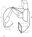
- FIG. 1 an example welding system 100 is shown in which a robot 102 is used to weld a workpiece 106 using a welding tool 108, such as the illustrated bent-neck (i.e., gooseneck design) welding torch (or, when under manual control, a handheld torch), to which power is delivered by welding equipment 110 via conduit 118 and returned by way of a ground conduit 120.
- the welding equipment 110 may comprise, inter alia , one or more power sources (each generally referred to herein as a "power supply"), a source of a shield gas, a wire feeder, and other devices.
- Other devices may include, for example, water coolers, fume extraction devices, one or more controllers, sensors, user interfaces, communication devices (wired and/or wireless), etc.
- the welding system 100 of Figure 1 may form a weld (e.g., at weld joint 112) between two components in a weldment by any known electric welding techniques.
- Known electric welding techniques include, inter alia , shielded metal arc welding (SMAW), MIG, flux-cored arc welding (FCAW), TIG, laser welding, sub-arc welding (SAW), stud welding, friction stir welding, and resistance welding.
- MIG, TIG, hot wire cladding, hot wire TIG, hot wire brazing, multiple arc applications, and SAW welding techniques, inter alia may involve automated or semi-automated external metal filler (e.g., via a wire feeder). In multiple arc applications (e.g.
- the preheater may pre-heat the wire into a pool with an arc between the wire and the pool.
- the welding equipment 110 may be arc welding equipment having one or more power supplies, and associated circuitry, that provides a direct current (DC), alternating current (AC), or a combination thereof to an electrode wire 114 of a welding tool (e.g., welding tool 108).
- the welding tool 108 may be, for example, a TIG torch, a MIG torch, or a flux cored torch (commonly called a MIG "gun").
- the electrode wire 114 may be tubular-type electrode, a solid type wire, a flux-core wire, a seamless metal core wire, and/or any other type of electrode wire.
- the welding tool 108 employs a contact tip assembly that heats the electrode wire 114 prior to forming a welding arc using the electrode wire 114.
- Suitable electrode wire 114 types includes, for example, tubular wire, metal cored wire, aluminum wire, solid gas metal arc welding (GMAW) wire, composite GMAW wire, gas-shielded FCAW wire, SAW wire, self-shielded wire, etc.
- the robot 102 which is operatively coupled to welding equipment 110 via conduit 118 and ground conduit 120, controls the location of the welding tool 108 and operation of the electrode wire 114 (e.g., via a wire feeder) by manipulating the welding tool 108 and triggering the starting and stopping of the current flow (whether a preheat current and/or welding current) to the electrode wire 114 by sending, for example, a trigger signal to the welding equipment 110.
- a welding arc is developed between the electrode wire 114 and the workpiece 106, which ultimately produces a weldment.
- the conduit 118 and the electrode wire 114 thus deliver welding current and voltage sufficient to create the electric welding arc between the electrode wire 114 and the workpiece 106.
- the welding arc locally melts the workpiece 106 and electrode wire 114 supplied to the weld joint 112, thereby forming a weld joint 112 when the metal cools.
- a human operator may control the location and operation of the electrode wire 114.
- an electrode wire 114 delivers the current to the point of welding on the workpiece 106 (e.g., a weldment).
- the operator could control the location and operation of the electrode wire 114 by manipulating the handheld torch and triggering the starting and stopping of the current flow via, for example, a trigger.
- a handheld torch generally comprises a handle, a trigger, a conductor tube, a nozzle at the distal end of the conductor tube, and a contact tip assembly.
- Applying pressure to the trigger i.e ., actuating the trigger
- a trigger signal i.e ., actuating the trigger
- the wire feeder is activated as needed (e.g. , to drive the electrode wire 114 forward to feed the electrode wire 114 and in reverse to retract the electrode wire 114).
- Commonly owned U.S. Patent No. 6,858,818 to Craig S. Knoener describes an example system and method of controlling a wire feeder of a welding-type system.
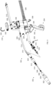
- FIG 2 illustrates an example liquid-cooled welding torch 200.
- the liquid-cooled welding torch 200 may be used to implement the welding tool 108 of Figure 1 to deliver the electrode wire 114 to a workpiece while providing both resistive preheating power and welding-type power.
- the liquid-cooled welding torch 200 includes a welding assembly 202, a mounting assembly 204, a weld cable 206, liquid cooling assemblies 208, 210, 212, 214, and a power and liquid transfer assembly 216.
- the example liquid-cooled welding torch 200 may be used to replace conventional robotic welding torches with resistive preheating-enabled welding torches having a same tool center point (TCP). By replacing a torch with another torch having a same TCP, the robot may be capable of continuing a welding program using the replacement torch with little or no reprogramming of tool points.
- the welding assembly 202 receives weld current and preheating current, conducts the weld current to the electrode wire 114, and conducts the preheating current through a portion of the electrode wire 114.
- the example welding assembly 202 is liquid-cooled by liquid provided via the liquid cooling assemblies 208-214.
- the example welding assembly 202 of Figure 2 receives the weld current via one or more of the weld cable 206, the liquid cooling assemblies 208 and 212, and/or the liquid cooling assemblies 210 and 214. Because the workpiece provides the return path for the weld current to the power supply, no return path is provided via the weld cable 206 or the liquid cooling assemblies 208.
- the weld cable 206 is an air-cooled (or gas-cooled) cable. However, the weld cable 206 may also be liquid-cooled.
- the example welding assembly 202 receives the preheating current via the weld cable 206, the liquid cooling assemblies 208 and 212, and/or the liquid cooling assemblies 210 and 214.
- the weld current is conducted via a different one of the weld cable 206, the liquid cooling assemblies 208 and 212, or the liquid cooling assemblies 210 and 214 than the preheating current that has the same polarity (i.e., current flow direction).
- the welding assembly 202 conducts the preheating current through a section of the electrode wire 114 to heat the electrode wire via resistive heating (e.g., I 2 R heating).
- the preheat current then returns to a preheating power supply via a different one of weld cable 206, the liquid cooling assemblies 208 and 212, or the liquid cooling assemblies 210 and 214 to complete a preheating circuit.
- the weld current path, the preheating current supply path, and the preheating current return path may all be different ones of the weld cable 206, the liquid cooling assemblies 208 and 212, and the liquid cooling assemblies 210 and 214.
- the weld current path may be superimposed with the preheating current supply path or the preheating current return path to reduce the net current in the conductor. For example, if the weld current is 300A and the preheating current is 100A, the weld current and the preheating current may be superimposed to result in a net current of 200A.
- the welding assembly 202 and the liquid cooling assemblies 212, 214 may be separated from the remainder of the liquid-cooled welding torch 200 via the power and liquid transfer assembly 216.
- Figure 3 illustrates an exploded view of the example liquid-cooled welding torch 200 of Figure 2 .
- the example welding assembly 202 includes a nozzle 302, a diffuser insulator 304, a first contact tip 306, a wire guide 308, a gas diffuser 310, a first contact tip insulator 312, a second contact tip 314, a second contact tip insulator 316, a nozzle mount 318, and a nozzle mount clamp 320.
- a liquid-cooled power cable assembly 322 includes the liquid cooling assemblies 212, 214, a cooler 324, and power connector pins 326, 328.
- the liquid-cooled power cable assembly 322 is described below in more detail with reference to FIGS. 6 , 7A , 7B , and 8 .
- the power and liquid transfer assembly 216 enables quick separation of the welding assembly 202 and the liquid-cooled power cable assembly 322 from the mounting assembly 204.
- the power and liquid transfer assembly 216 includes a saddle 330, a saddle cover 332, a saddle clasp 334, and saddle clamps 336.
- the power and liquid transfer assembly 216 is described below in more detail with reference to Figures 4 and 5 .
- the example mounting assembly 204 includes a torch body 338, a neck 340, and a robot link assembly 342 including, for example, a bracket, a link arm, and a robot mounting disk.
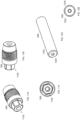
- Figure 4 is a more detailed depiction of an example liquid cooling assembly 400 that may be used to implement the liquid cooling assemblies 208, 210 of Figure 2 .
- Figure 5 is a cross-section view of the liquid cooling assembly 400 of Figure 4 .
- the liquid cooling assembly 400 includes a power cable socket 402 that holds a power transfer socket 404 and a liquid shutoff valve 406.
- the liquid cooling assembly 400 also includes a hose 408 and an internal conductor 410.
- the hose 408 is coupled to the power cable socket 402 on a first end and coupled to a power cable fitting 412 on a second end.
- the power cable socket 402 receives one of the power connector pins 326, 328 to transfer cooling liquid and welding current and/or preheating current to a corresponding one of the liquid cooling assemblies 212, 214.
- the power transfer socket 404 enables insertion of the power connector pin 326, 328, and transfers current to and/or from an inserted power connector pin 326, 328.
- An example power transfer socket that may be used to implement the power transfer socket 404 is a PowerBud ® power contact, sold by Methode Electronics, Inc., which provides multiple contact points between the power transfer socket and an inserted power connector pin 326, 328.
- the liquid shutoff valve 406 selectively permits flow of liquid from the hose 408 to the power transfer socket 404 and to a connected liquid cooling assembly 212, 214.
- the example liquid shutoff valve 406 is a Schrader valve. However, other types of valves may be used to implement the liquid shutoff valve 406.
- a power connector pin 326, 328 When a power connector pin 326, 328 is inserted (e.g., fully inserted) into the power transfer socket 404, the power connector pin 326, 328 displaces (e.g., unseats) a stem 414 from a core 416 of the valve 406, which permits liquid to flow to and/or from the hose 408.
- the stem 414 is forced back into the core 416 and stops flow of liquid.
- the hose 408 is coupled to the power cable fitting 412 via a ferrule 418 and a fitting nut 420.
- the power cable fitting 412 is coupled to a source of weld current and/or preheating current, and is electrically connected to transfer the weld current and/or preheating current to or from the internal conductor 410 of the hose 408.
- the hose 408 is also coupled to the power cable socket 402 via a ferrule 418.
- the example power cable fitting 412, the example power cable socket 402, and/or the hose 408 include hose barbs to secure the hose 408.
- other methods of securing the hose to the power cable fitting 412 and/or the power cable socket 402 may be used, such as clamps, compression fittings, or any other hose fittings.
- the example liquid cooling assembly 400 permits liquid to flow through the power cable fitting 412, the hose 408, the valve 406, the power cable socket 402, and the power transfer socket 404, either to or from the liquid cooling device (e.g., based on whether the assembly is configured as the liquid supply or the liquid return).
- the example liquid cooling assembly 400 also conducts current from and/or to a weld power supply and/or a preheating power supply. For example, the current is conducted through the power cable fitting 412, the internal conductor 410, the power cable socket 402, and the power transfer socket 404.
- FIG 6 is an exploded view of the example liquid-cooled power cable assembly 322 of Figure 3 .
- the liquid-cooled power cable assembly 322 provides cooling liquid supply and return paths from the liquid cooling assemblies 212, 214 to the welding assembly 202 of Figure 3 .
- the liquid-cooled power cable assembly 322 includes the liquid cooling assemblies 212, 214, the power connector pins 326, 328, a cooling body 602, and a cooling body cover 604.
- Each of the example liquid cooling assemblies 212, 214 includes three layers: an inner conductive layer 606a, 606b; an insulative layer 608a, 608b; and an outer protective layer 610a, 610b.
- the inner conductive layer 606a, 606b conduct current and liquid, and is constructed of a conductive material such as copper.
- the insulative layers 608a, 608b provide electrical insulation between the inner conductive layers 606a, 606b and the outer protective layers 610a, 610b.
- the example insulative layers 608a, 608b may be silicone, PTFE, PET, and/or any other suitable electrically insulative material or combination of materials.
- the outer protective layers 610a, 610b provide rigidity and/or physical protection from damage, such as punctures.
- the outer protective layers 610a, 610b may be a rigid material such as aluminum or any other appropriate material or combination of materials.
- two or more of the layers 606a-610a, 606b-610b may be combined.
- the insulative layers 608a, 608b may also serve as the outer protective layers 610a, 610b, or vice versa.
- the outer protective layers 610a, 610b may be omitted.
- the inner conductive layers 606a, 606b are contained within the insulative layers 608a, 608b.
- the insulative layers 608a, 608b are similar contained within the outer protective layers 610a, 610b.
- the cooling body 602 circulates the liquid through a tortuous path 612 between a liquid input port and a liquid output port.
- the cooling body 602 is coupled to the welding assembly 202 to conduct heat from the components in the welding assembly 202 to the liquid, thereby cooling the welding assembly 202.
- the cooling body cover 604 is attached to the cooling body 602 to contain the fluid within the tortuous path 606.
- the cooling body 602 and a cooling body cover 604 may be a single unit (e.g., constructed using additive manufacturing techniques).
- Figures 7A, 7B, and 7C are views of the example cooler body 602 of Figure 6 .
- the tortuous path 612 includes a continuous path around a circumference of the cooler body 602.
- the liquid cooling assembly 214 supplies cooling liquid to the cooler body 602 and the liquid cooling assembly 212 returns the cooling liquid to a liquid cooler.
- the cooling liquid follows a flow path 702 (shown using a dotted line) through the tortuous path 612 to increase heat transfer from the welding assembly 202 to the liquid.
- Continuities A and B from one view to the next are shown in Figures 7A, 7B, and 7C .
- Figure 8 is a cross-section view of the liquid cooling assembly 212, 214 and the power and liquid transfer assembly 216 of Figure 2 coupled to the liquid cooling assembly 400 of Figure 4 .
- the power cable socket 402 is seated in the saddle 330, which prevents movement of the power cable socket 402.
- the example power connector pin 326 is inserted into the power cable socket 402 and the power transfer socket 404.
- the power connector pin 326 includes an inner liquid coolant passage 802, one or more liquid coolant ports 804 to enable liquid to flow into and/or out of the liquid coolant passage 802, and a seal 806.
- the power connector pin 326 opens the valve 406 to permit liquid to flow through the valve 406, the liquid coolant ports 804, the liquid coolant passage 802, and the inner conductive layer 606a.
- a retaining ring 808 may be included in the saddle cover 332 to hold the power connector pin 326 in place.
- the example power connector pin 326 In addition to placing the liquid cooling assembly 212 in fluid communication with the liquid cooling assembly 208, the example power connector pin 326 also conducts weld current and/or preheating current between the liquid cooling assembly 212 and the liquid cooling assembly 208.
- the example inner conductive layer 606a is in electrical contact with the power transfer pin 326, which is a conductive material (e.g., copper) and is in electrical contact with the power transfer socket 404.
- FIG 9 illustrates the example welding assembly 202 and the example liquid cooling assemblies 212, 214 of Figure 2 disconnected from the remainder of the torch 200 via the power and liquid transfer assembly 216.
- the example saddle clasp 334 is unhooked or otherwise detached from a retention pin 902 on the saddle 330.
- the power connector pin 328 can be disengaged from the power cable socket 402 and the saddle cover 332 can be simultaneously lifted from the saddle 330.
- the power connector pins 326, 328 are inserted into corresponding power cable sockets 402 while the saddle cover 332 is placed onto the saddle 330.
- the saddle clasp 334 is hooked into the retention pin 902 to hold the power connector pins 326, 328 in place.
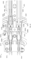
- FIG 10 is a cross-section view of the example welding assembly 202 of Figure 2 .
- the welding assembly 202 is liquid-cooled via the liquid cooling assemblies 212, 214.
- the liquid cooling assemblies 212, 214 and/or a torch neck 1002 provide weld current and preheating current to the welding assembly 202 for preheating the electrode wire 114 and for generating a welding arc.
- the example welding assembly 202 includes the nozzle 302, the diffuser insulator 304, the first contact tip 306, the wire guide 308, the gas diffuser 310, the first contact tip insulator 312, the second contact tip 314, the second contact tip insulator 316, the nozzle mount 318, the nozzle mount clamp 320, the cooling body 602, and the cooling body cover 604.
- the welding assembly 202 is attached to a torch neck 1002, through which a wire liner 1004 conveys the electrode wire 114 and/or shielding gas to the welding assembly 202.
- the first contact tip 306 delivers welding current to the electrode wire 114 for arc welding.
- the first contact tip 306 is threaded into a gas diffuser 310, which is in turn threaded into the diffuser insulator 304.
- the diffuser insulator 304 provides electrical and thermal insulation between the gas diffuser 310 and the nozzle 302.
- the gas diffuser 310 is threaded into the cooling body 602.
- the cooling body 602 conducts welding current and/or preheating current from the liquid-cooled power cable assembly 322 (e.g., from the inner conductive layer(s) 606a, 606b) to the diffuser 310, which is electrically connected to the first contact tip 306.
- the first contact tip insulator 312 and the diffuser insulator 304 provide electrical insulation between the weld current and preheat current path(s) and the nozzle 302.
- the second contact tip 314 is electrically coupled to the torch neck 1002 to conduct preheating current to and/or from the electrode wire 114.
- the preheating circuit includes the torch neck 1002, the second contact tip 314, the first contact tip 306, a portion of the electrode wire 1006 between the second contact tip 314 and the first contact tip 306, the diffuser 310, the cooling body 602, and one or both of the inner conductive layers 606a, 606b in the liquid-cooled power cable assembly 322.
- the second contact tip insulator 316 provides electrical insulation between the second contact tip 314 and the cooling body 602.
- the second contact tip insulator 316 includes a seal 1008 (e.g., an o-ring) to reduce or prevent welding gas leakage.
- the nozzle mount 318 and the nozzle mount clamp 320 provide an attachment point for threading the welding assembly 202 onto the torch neck 1002.
- the nozzle mount 318 physically couples and/or provides support to the liquid-cooled power cable assembly 322 from the torch neck 1002, which is rigid.
- the welding assembly 202 may be completely or partially disassembled to access one or more of the components in the welding assembly 202.
- first contact tip 306, the wire guide 308, and/or the second contact tip 314 are removable via the tip of the nozzle 302.
- Figures 11A, 11B, and 11C show an example implementation of the first contact tip 306
- Figures 12A and 12B show an example implementation of the wire guide 308,
- Figures 13A, 13B, and 13C show an example implementation of the second contact tip 314.
- a first end 1102 of the first contact tip 306 has a hexagonal cross-section.
- the hexagonal cross-section enables the first contact tip 306 to be unthreaded from the diffuser 310 via the opening in the nozzle 302.
- Other exterior geometries may be used for the cross-section of the first end 1102 of the first contact tip 306.
- an interior geometry may be used (e.g., in combination with a corresponding tool) to unthread the first contact tip 306 from the diffuser 310.
- the wire guide 308 may also be removed via the nozzle 302. As shown in Figures 10 , 12A, and 12B , an outer surface 1202 of the wire guide 308 is relatively smooth (e.g., not threaded) and can be inserted into and removed from of an inner diameter 1010 of the cooling body 602 without threading.
- the wire guide 308 has a wire path 1204 to guide the wire from the second contact tip 314 to the first contact tip 306.
- the wire guide 308 is a nonconductive material such as ceramic, so that the electrode wire 114 is the only conductive path between the second contact tip 314 and the first contact tip 306.
- the second contact tip 314 includes a hexagonal cross-section on a first end 1302 of the second contact tip 314.
- An interior surface 1304 and/or an exterior surface 1306 (e.g., a head) of the first end 1302 provides the hexagonal cross-section and/or any other shape that enables the second contact tip to be unthreaded from the torch neck 1002.
- the example second contact tip 314 includes threads 1305 to enable the second contact tip 314 to be threaded into the second contact tip insulator 316.
- the exterior surface 1306 has a smaller diameter than the major diameter of the threads 1305, which can improve access to the exterior surface 1306 for removal and/or installation of the second contact tip 314.
- the outer diameter of the second contact tip 314 is equal to or less than the inner diameter 1010 of the cooling body 602 and less than an inner diameter 1012 of the second contact tip insulator 316 to enable the second contact tip 314 to be removed via the tip of the nozzle 302, the cooling body 602, and the second contact tip insulator 316.
- the first end 1302 may be manipulated (e.g., via a tool inserted through the nozzle 302) to unthread the second contact tip 314 from the torch neck 1002, after which the second contact tip 314 can be removed from the welding assembly 202 without disassembly of the welding assembly 202.
- the second contact tip 314 includes slots 1308 running longitudinally on the exterior of the second contact tip 314 through the threads 1305.
- the slots 1308 permit the flow of welding gas from the interior of the torch neck 1002 to the diffuser 310 via the cooling body 602 (e.g., through the interior of the cooling body 602 through and/or around the wire guide 308.
- the second contact tip 314 includes a first bore 1310 having a first diameter.
- the electrode wire 114 makes electrical contact with the first bore 1310.
- the example second contact tip 314 may also have a second, larger bore 1312 on a rear side of the contact tip 314 from the first bore 1310.
- the length of the second bore 1312 may be selected to control a contact length of the first bore 1310.
- the example contact tip 314 may have an insert 1012 inserted within the first bore 1310 to improve contact with the electrode wire 114, improve current transfer with the electrode wire 114, and/or improve mechanical strength at operating temperatures.
- Figures 14A and 14B illustrate views of the example diffuser 310 of Figures 3 and 10 .
- the diffuser 310 includes two sets of exterior threads for installation into the diffuser insulator 304 and the cooling body 602, and a set of interior threads for installation of the first contact tip 306 into the diffuser 310.
- the diffuser 310 includes gas outlets 1402 to enable the flow of gas from the inner diameter 1010 of the cooling body 602 to the nozzle 302 for output to the weld.
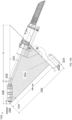
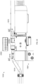
- Figure 15A illustrates a conventional robotic welding torch 1500 having a first tool center point distance and torch neck angle.
- Figure 15B illustrates an example implementation of the liquid-cooled welding torch 200 of Figure 2 configured to replace the conventional torch 1500 of Figure 15A while maintaining a same tool center point distance and torch neck angle.
- the tool center point distance 1502 of the conventional torch 1500 is a function of a stickout distance 1504, a nozzle length 1506, a nozzle angle 1508, a neck bend angle 1510, a tool center point area 1512, and a spacer width 1514.
- the tool center point area 1512 e.g., Area TCP
- Area TCP 0.5 ⁇ TCP ⁇ spacer width 1514 2 ⁇ TAN nozzle angle 1508 + TCP ⁇ spacer width 1514 ⁇ nozzle length 1506 + stickout 1504 ⁇ COS nozzle angle 1508 2 ⁇ TAN nozzle angle 1508 ⁇ neck bend angle 1510 ⁇ 1
- the example welding assembly 202 described above with reference to Figures 10 , 11A-11C, 12A, 12B , 13A-13C , 14A , and/or 14B may have a same nozzle length 1506 as conventional nozzles. In other examples, the welding assembly 202 may require a longer nozzle 302 than a nozzle of the conventional torch. In some examples, such as the welding torch described below with reference to Figures 19-23 , the welding assembly may have a nozzle that is shorter than conventional nozzles. However, the length of the example torch neck 1002 and/or the length and/or one or more dimensions of the example mounting assembly 204 may be adjusted to compensate for differences in the nozzle length.
- the example liquid-cooled welding torch 200 may be dimensioned to be a replacement for any standard tool center point distance (e.g., 350mm, 400mm, 450mm, 500mm, etc.) and/or torch neck angle (e.g., 0 degree, 22 degree, 35 degree, 45 degree, etc.) to maintain the same TCP, torch neck angle, and tool center point area after replacement.
- disclosed example welding assemblies 202 and/or liquid-cooled welding torches 200 may be used as replacements for conventional robotic weld torches such that a robot on which the replacement occurs does not require reprogramming or recalibration of new tool center point(s) or torch neck angle(s).
- the robot subject to replacement is capable of higher deposition rates, improved welding starts, and/or other advantages over conventional welding torches.
- reprogramming of welding voltages, currents, and/or torch travel speeds may be performed to realize the advantages of the liquid-cooled welding torch 200 for previously programmed welding tasks.
- the example welding torch 200 includes a preheat distance 1516 within the nozzle.
- the nozzle length 1506 is subdivided into the stickout distance 1504, the preheat distance 1516, and a neck-to-contact tip length 1518.
- the conventional torch 1500 may be considered to have a preheat distance 1516 of 0.
- the replacement By replacing a conventional weld torch 1500 with a weld torch 200 having substantially the same tool center point distance 1502, the stickout distance 1504, the nozzle length 1506, the nozzle angle 1508, the neck bend angle 1510, and the tool center point area 1512, the replacement reduces the programming needed to avoid an increased risk of collisions.
- Tables 1 and 2 below illustrates example comparisons of the dimensions 1502-1516 for two example tool center point distances 1502, 350mm and 400mm.
- a welding torch having a preheat length of 3.29 inches may be used with an air-cooled torch.
- a welding torch having a preheat length of 2.40 inches results in a nozzle length 1506 and TCP area 1512 of a welding torch 200 that substantially match the nozzle length and TCP area 1512 of the conventional torch 1500.
- the current density may increase enough to require an increase in the radius of the welding assembly 202 (e.g., increased components in the welding assembly 202) to continue to use air cooling (as in torches 2 and 5 of Tables 1 and 2).
- the preheat distance of 2.40 inches may be used with the example liquid cooled welding torch 200 disclosed herein.
- any of the dimensions of Tables 1 and 2 may be selected based on a specification of another of the dimensions.
- the preheating length (and, thus, the dimensions of the welding assembly) may be selected based on any of the TCP, the stickout, the neck-to-contact tip length, the nozzle length, the nozzle angle, the neck angle, and/or the TCP area.
- the neck-to-contact tip length is based on at least one of a nozzle length, a preheat distance, a nozzle angle, or a neck angle.
- Preheat lengths 1516 that are longer than the 3.29 inches of the examples of Tables 1 and 2 may result in a torch envelope that is larger than the envelope of the conventional torches 1500 by more than an acceptable amount. Torches having an envelope that is excessively large may require more robot programming to serve as a replacement for a conventional torch and/or has a higher chance of collision during operation. Additional programming and collisions are undesirable effects of replacement, and disclosed examples reduce or prevent such effects while providing the benefits of electrode preheating at the welding assembly 202.
- the example welding assembly 202 includes the first contact tip 306 and the second contact tip 314 such that both of the contact tips 306, 314 are on a distal end of the bend in the torch neck 1002, in some other examples the second contact tip 314 is on a proximal side of the bend in the torch neck 1002. Additionally or alternatively, a third contact tip is further located on the proximal side of the bend in the torch neck 1002 so that preheating occurs between the second contact tip 314 (on either side of the bend) and the third contact tip (on the proximal side of the bend).
- the column strength of the electrode wire 114 may be reduced to a point that the heated electrode wire 114 can no longer be pushed around the bend in the torch neck 1002 without buckling.
- the liquid-cooled welding torch 200 is provided with a pull motor to assist the push motor located in the wire feeder.
- the bend in the torch neck 1002 may be provided with ceramic bearings to reduce the friction force between the wire liner 1004 and the electrode wire 114, which increases the temperature to which the electrode wire 114 may be preheated before buckling becomes likely.
- the length between the first and second contact tips 306, 314 (e.g., the preheat length) is adjustable to change the length of the electrode wire 114 that is being preheated. As the preheat length increases, the energy added to the electrode wire 114 is increased per unit of current. To change the preheat length, one or both of the contact tips 306, 314 may be configured to be translated in the axial direction via manual and/or automatic methods.
- the second contact tip 314 may be threaded into an intermediate device between the second contact tip 314 and the torch neck 1002.
- the intermediate device may be automatically rotated (e.g., with a motor coupled to the contact tip) and/or manually rotated (e.g., with a thumb wheel or other device configured to cause rotation in the contact tip) while limiting rotation of the second contact tip 314, which causes the threads of the second contact tip 314 to carry the second contact tip 314 toward or away from the first contact tip 306.
- first and/or second contact tips 306, 314 may be configured to be reversible to change the preheat length. For example, if the first contact tip 306 has a contact location with the electrode wire 114 that is closer than a midpoint of the first contact tip 306 to the second contact tip 314, reversing the first contact tip 306 changes the contact location with the electrode wire 114 and extends the preheat length. In some examples, different contact tips have different contact points, so that changing contact tips changes the preheat length. In some other examples, the welding assembly 202 may be replaced with a different welding assembly that has a different preheat length such as different spacing between the contact tips 306, 314 (which may require a different robotic program to be run that accounts for a different nozzle length).
- the change in preheat length may be automatically controlled based on, for example, a temperature of the electrode wire 114 and/or based on a desired preheat level or heat input to the weld specified by a user.
- a current controlled control loop is used to control preheat current when the preheat length is automatically adjustable.
- the power and liquid transfer assembly 216 is attached to the torch body 338 on a side of the torch body 338 opposite the mounting assembly 204, or opposite a direction of the bend in the torch neck 1002. Because the power and liquid transfer assembly 216 increasing a volume of the torch 200, locating the power and liquid transfer assembly 216 opposite the mounting assembly 204 and/or opposite a direction of the bend in the torch neck 1002 may reduce the chances of collision with a workpiece when using the same program with the replacement preheating weld torch 200 as used with a conventional weld torch.
- the welding assembly 202 may be provided with a wire oscillator to cause physical oscillation or weave at a tip of the electrode wire 114.
- a wire oscillator to cause physical oscillation or weave at a tip of the electrode wire 114.
- An example implementation of the wire oscillator that may be used to provide wire oscillation is described in U.S. Patent 4,295,031 .
- disclosed example welding torches may provide both wire oscillation and resistive preheating to a weld to further improve deposition rates and weld quality.
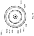
- Figure 16 is a cross section of an example welding cable 1600 that may be used to provide cooling liquid, welding current, and preheating current to a welding torch, and to carry cooling liquid away from the welding torch.
- the example welding cable 1600 may be used instead of the liquid cooling assemblies 208, 210, in cases in which the first contact tip 306 is part of the preheating circuit and the welding circuit.
- the welding cable 1600 is a coaxial-type welding cable, in which the electrode wire 114 is fed through a wire guide 1602.
- the wire guide 1602 is surrounded by a jacket 1604.
- a first conductor 1606 provides a first electrical path for preheating current, or welding current and preheating current.
- the first conductor 1606 may be, for example, a copper sheath or webbing rated to conduct welding current.
- the first conductor 1606 is surrounded by a jacket 1608.
- a second conductor 1610 provides a second electrical path for preheat current, or welding current and preheating current.
- a first one of the first conductor 1606 or the second conductor 1610 provides a path for the preheating current and is coupled to a preheating power supply.
- the second conductor 1610 is surrounded by a jacket 1612.
- another protective layer may be present outside of the jacket 1612 to protect the welding cable 1600 from damage.
- the jacket 1612 provides both physical and electrical protection to the cable 1600.
- An annulus 1614 between the jacket 1604 and the first conductor 1606 and/or the jacket 1608 conducts cooling liquid in a first direction (e.g., from a liquid cooler to the welding torch, from the welding torch to the liquid cooler).
- An annulus 1616 between the jacket 1608 and the second conductor 1610 and/or the jacket 1612 conducts the cooling liquid in a second direction opposite the liquid flow direction in the annulus 1614.
- FIG 17 illustrates a functional diagram of an example welding system 1700 including the example welding torch 200 of Figure 2 , and which may be used with the welding system 100 of Figure 1 .
- the welding system 1700 includes the weld torch 200 having the first contact tip 306 and a second contact tip 314.
- the system 1700 further includes the electrode wire 114 fed from a wire feeder 1702 having a wire drive 1704 and a wire spool 1706, a preheating power supply 1708, and a welding power supply 1710.
- the system 1700 is illustrated in operation as producing a welding arc 1712 between the electrode wire 114 and a workpiece 106.
- the electrode wire 114 passes from the wire spool 1706 through the second contact tip 314 and the first contact tip 306, between which the preheating power supply 1708 generates a preheating current to heat the electrode wire 114.
- the preheating current enters the electrode wire 114 via the second contact tip 314 (e.g., via the wire drive 1704 and/or the torch neck 1002 of Figure 10 ) and exits via the first contact tip 306.
- a welding current may also enter the electrode wire 114 (e.g., via the liquid cooling assemblies 208 and 212, and/or 210 and 214.
- the welding current is generated, or otherwise provided by, the welding power supply 1710.
- the welding current exits the electrode wire 114 via the workpiece 106, which in turn generates the welding arc 1712.
- an electrical circuit is completed and the welding current flows through the electrode wire 114, across the metal work piece(s) 106, and returns to the welding power supply 1710.
- the welding current causes the electrode wire 114 and the parent metal of the work piece(s) 106 in contact with the electrode wire 114 to melt, thereby joining the work pieces as the melt solidifies.
- a welding arc 1712 may be generated with drastically reduced arc energy.
- the preheating current is proportional to the distance between the contact tips 306, 314 and the electrode wire 114 size.
- the welding current is generated, or otherwise provided by, a welding power supply 1710, while the preheating current is generated, or otherwise provided by, the preheating power supply 1708.
- the preheating power supply 1708 and the welding power supply 1710 may ultimately share a common power source (e.g., a common generator or line current connection), but the current from the common power source is converted, inverted, and/or regulated to yield the two separate currents - the preheating current and the welding current.
- the preheat operation may be facilitated with a single power source and associated converter circuitry, in which case three leads may extend from a single power source.
- the system 1700 establishes a welding circuit to conduct welding current from the welding power supply 1710 to the first contact tip 306 via the liquid cooling assemblies 208 and 212 and/or 210 and 214, and returns to the power supply 1710 via the welding arc 1712, the workpiece 106, and a work lead 1718.
- the welding power supply 1710 includes terminals 1720, 1722 (e.g., a positive terminal and a negative terminal).
- the preheating power supply establishes a preheating circuit to conduct preheating current through a section 1726 of the electrode wire 114.
- the preheating power supply 1708 includes terminals 1728, 1730.
- the preheating current flows from the welding power supply 1710 to the second contact tip 314 (e.g., via the torch neck 1002), the section 1726 of the electrode wire 114, the first contact tip 306, and returns to the preheating power supply 1708 via a cable 1732 connecting the terminal 1720 of the welding power supply 1710 to the terminal 1730 of the preheating power supply 1708.
- the cable 1732 may enable a more cost-effective single connection between the first contact tip 306 and the power supplies 1708, 1710 (e.g., a single cable) than providing separate connections for the welding current to the first contact tip 306 and for the preheating current to the first contact tip 306.
- the terminal 1730 of the preheating power supply 1708 is connected to the first contact tip 306 via a separate path than the path between the first contact tip 306 and the welding power supply 1710.
- the welding current may be conducted via the liquid cooling assemblies 208 and 212 while the preheating current is conducted via the liquid cooling assemblies 210 and 214 (or vice versa).
- the welding torch may include a push-pull wire feed system by including a feed motor located at or near the weld torch to pull the electrode wire 114.
- the inclusion of the pulling feed motor enables the portion of the electrode wire 114 that is preheated to a different location along the wire feed path than in the examples of Figures 2 , 3 , and 10 .
- the second contact tip 314 may be moved into the neck 1002 (e.g., prior to the bend in the torch neck 1002 in the feed direction of the electrode wire 114) and/or in the torch body (e.g., the mounting assembly 204 of Figure 2 ) and/or multiple contact tips may be positioned at locations along the length of the electrode wire 114 to provide a preheating circuit that is separate from the welding circuit (e.g., does not share a same contact tip with the welding circuit) and/or provides an additional preheating circuit (e.g., a first preheating current applied to a first portion of the electrode wire 114 and a second preheat current applied to a second portion of the preheating wire).
- a preheating circuit e.g., a first preheating current applied to a first portion of the electrode wire 114 and a second preheat current applied to a second portion of the preheating wire.
- the idler roller of a push-pull wire feed system may function as a contact tip to conduct preheating current.
- the size of the welding assembly may be reduced, the preheat length may be increased, and/or the preheating current may be reduced. Reduction in the size of the welding assembly and reduction in the preheating current enables torch dimensions that are closer to those of conventional, non-resistive preheating torches, further improving the ease of replacement of conventional torches with torches providing resistive preheating.
- FIG 18 is a block diagram of an example implementation of the power supplies 1708, 1710 of Figure 17 .
- the example power supply 1708, 1710 powers, controls, and supplies consumables to a welding application.
- the power supply 1708, 1710 directly supplies input power to the welding tool 108.
- the power supply 1708, 1710 is configured to supply power to welding operations and/or preheating operations.
- the example power supply 1708, 1710 also provides power to a wire feeder to supply the electrode wire 114 to the welding tool 108 for various welding applications (e.g., GMAW welding, flux core arc welding (FCAW)).
- GMAW welding GMAW welding
- FCAW flux core arc welding
- the power supply 1708, 1710 receives primary power 1808 (e.g., from the AC power grid, an engine/generator set, a battery, or other energy generating or storage devices, or a combination thereof), conditions the primary power, and provides an output power to one or more welding devices and/or preheating devices in accordance with demands of the system.
- the primary power 1808 may be supplied from an offsite location (e.g., the primary power may originate from the power grid).
- the power supply 1708, 1710 includes a power converter 1810, which may include transformers, rectifiers, switches, and so forth, capable of converting the AC input power to AC and/or DC output power as dictated by the demands of the system (e.g., particular welding processes and regimes).
- the power converter 1810 converts input power (e.g., the primary power 1808) to welding-type power based on a weld voltage setpoint and outputs the welding-type power via a weld circuit.
- the power converter 1810 is configured to convert the primary power 1808 to both welding-type power and auxiliary power outputs. However, in other examples, the power converter 1810 is adapted to convert primary power only to a weld power output, and a separate auxiliary converter is provided to convert primary power to auxiliary power. In some other examples, the power supply 1708, 1710 receives a converted auxiliary power output directly from a wall outlet. Any suitable power conversion system or mechanism may be employed by the power supply 1708, 1710 to generate and supply both weld and auxiliary power.
- the power supply 1708, 1710 includes a controller 1812 to control the operation of the power supply 1708, 1710.
- the power supply 1708, 1710 also includes a user interface 1814.
- the controller 1812 receives input from the user interface 1814, through which a user may choose a process and/or input desired parameters (e.g., voltages, currents, particular pulsed or non-pulsed welding regimes, and so forth).
- the user interface 1814 may receive inputs using any input device, such as via a keypad, keyboard, buttons, touch screen, voice activation system, wireless device, etc.
- the controller 1812 controls operating parameters based on input by the user as well as based on other current operating parameters.
- the user interface 1814 may include a display 1816 for presenting, showing, or indicating, information to an operator.
- the controller 1812 may also include interface circuitry for communicating data to other devices in the system, such as the wire feeder.
- the power supply 1708, 1710 wirelessly communicates with other welding devices within the welding system.
- the power supply 1708, 1710 communicates with other welding devices using a wired connection, such as by using a network interface controller (NIC) to communicate data via a network (e.g., ETHERNET, 10baseT, 10base100, etc.).
- NIC network interface controller
- the controller 1812 communicates with the wire feeder via the weld circuit via a communications transceiver 1818.
- the controller 1812 includes at least one controller or processor 1820 that controls the operations of the welding power supply 1802.
- the controller 1812 receives and processes multiple inputs associated with the performance and demands of the system.
- the processor 1820 may include one or more microprocessors, such as one or more "general-purpose" microprocessors, one or more special-purpose microprocessors and/or ASICS, and/or any other type of processing device.
- the processor 1820 may include one or more digital signal processors (DSPs).
- DSPs digital signal processors
- the example controller 1812 includes one or more storage device(s) 1823 and one or more memory device(s) 1824.
- the storage device(s) 1823 e.g., nonvolatile storage
- the storage device 1823 stores data (e.g., data corresponding to a welding application), instructions (e.g., software or firmware to perform welding processes), and/or any other appropriate data. Examples of stored data for a welding application include an attitude (e.g., orientation) of a welding torch, a distance between the contact tip and a workpiece, a voltage, a current, welding device settings, and so forth.
- the memory device 1824 may include a volatile memory, such as random access memory (RAM), and/or a nonvolatile memory, such as read-only memory (ROM).
- RAM random access memory
- ROM read-only memory
- the memory device 1824 and/or the storage device(s) 1823 may store a variety of information and may be used for various purposes.
- the memory device 1824 and/or the storage device(s) 1823 may store processor executable instructions 1825 (e.g., firmware or software) for the processor 1820 to execute.
- one or more control regimes for various welding processes may be stored in the storage device 1823 and/or memory device 1824, along with code configured to provide a specific output (e.g., initiate wire feed, enable gas flow, capture welding current data, detect short circuit parameters, determine amount of spatter) during operation.
- a specific output e.g., initiate wire feed, enable gas flow, capture welding current data, detect short circuit parameters, determine amount of spatter
- the welding power flows from the power converter 1810 through a weld cable 1826.
- the example weld cable 1826 is attachable and detachable from weld studs at each of the power supply 1708, 1710 (e.g., to enable ease of replacement of the weld cable 1826 in case of wear or damage).
- welding data is provided with the weld cable 1826 such that welding power and weld data are provided and transmitted together over the weld cable 1826.
- the communications transceiver 1818 is communicatively coupled to the weld cable 1826 to communicate (e.g., send/receive) data over the weld cable 1826.
- the communications transceiver 1818 may be implemented based on various types of power line communications methods and techniques.
- the communications transceiver 1818 may utilize IEEE standard P1901.2 to provide data communications over the weld cable 1826.
- the weld cable 1826 may be utilized to provide welding power from the power supply 1708, 1710 to the wire feeder and the welding tool 108.
- the weld cable 1826 may be used to transmit and/or receive data communications to/from the wire feeder and the welding tool 108.
- the communications transceiver 1818 is communicatively coupled to the weld cable 1826, for example, via cable data couplers 1827, to characterize the weld cable 1826, as described in more detail below.
- the cable data coupler 1827 may be, for example, a voltage or current sensor.
- the power supply 1708, 1710 includes or is implemented in a wire feeder.
- the example communications transceiver 1818 includes a receiver circuit 1821 and a transmitter circuit 1822.
- the receiver circuit 1821 receives data transmitted by the wire feeder via the weld cable 1826 and the transmitter circuit 1822 transmits data to the wire feeder via the weld cable 1826.
- the communications transceiver 1818 enables remote configuration of the power supply 1708, 1710 from the location of the wire feeder and/or compensation of weld voltages by the power supply 1708, 1710 using weld voltage feedback information transmitted by the wire feeder 104.
- the receiver circuit 1821 receives communication(s) via the weld circuit while weld current is flowing through the weld circuit (e.g., during a welding-type operation) and/or after the weld current has stopped flowing through the weld circuit (e.g., after a welding-type operation).
- Examples of such communications include weld voltage feedback information measured at a device that is remote from the power supply 1708, 1710 (e.g., the wire feeder) while the weld current is flowing through the weld circuit
- Example implementations of the communications transceiver 1818 are described in U.S. Patent No. 9,012,807 . However, other implementations of the communications transceiver 1818 may be used.
- the example wire feeder 104 also includes a communications transceiver 1819, which may be similar or identical in construction and/or function as the communications transceiver 1818.
- a gas supply 1828 provides shielding gases, such as argon, helium, carbon dioxide, and so forth, depending upon the welding application.
- the shielding gas flows to a valve 1830, which controls the flow of gas, and if desired, may be selected to allow for modulating or regulating the amount of gas supplied to a welding application.
- the valve 1830 may be opened, closed, or otherwise operated by the controller 1812 to enable, inhibit, or control gas flow (e.g., shielding gas) through the valve 1830.
- Shielding gas exits the valve 1830 and flows through a cable 1832 (which in some implementations may be packaged with the welding power output) to the wire feeder which provides the shielding gas to the welding application.
- the power supply 1708, 1710 does not include the gas supply 1828, the valve 1830, and/or the cable 1832.
- Figure 19 illustrates another example liquid-cooled welding torch 1900.
- the example liquid-cooled welding torch 1900 resistively preheats an electrode wire 114 via multiple contact points (e.g., contact tips) in the torch 1900.
- the torch 1900 of Figure 19 includes a welding assembly 1902, a mounting assembly 1904, a weld cable 1906, liquid cooling assemblies 1908, 1910, 1912, 1914, and a power and liquid transfer assembly 1916.
- the example liquid-cooled welding torch 1900 may be used to replace conventional robotic welding torches with resistive preheating-enabled welding torches having a same tool center point (TCP).
- the welding assembly 1902 receives weld current and preheating current, conducts the weld current to the electrode wire 114, and conducts the preheating current through a portion of the electrode wire 114.
- the example welding assembly 1902 is liquid-cooled by liquid provided via the liquid cooling assemblies 1908-214.
- the example welding assembly 1902 of Figure 19 receives the weld current via one or more of the weld cable 1906, the liquid cooling assemblies 1908 and 1912, and/or the liquid cooling assemblies 1910 and 1914. Because the workpiece provides the return path for the weld current to the power supply, no return path is provided via the weld cable 1906 or the liquid cooling assemblies 1908.
- the weld cable 1906 is a air-cooled (or gas-cooled) cable. However, the weld cable 1906 may also be liquid-cooled.
- the example welding assembly 1902 receives the preheating current via the weld cable 1906, the liquid cooling assemblies 1908 and 1912, and/or the liquid cooling assemblies 1910 and 1914.
- the weld current is conducted via a different one of the weld cable 1906, the liquid cooling assemblies 1908 and 1912, or the liquid cooling assemblies 1910 and 1914 than the preheating current that has the same polarity (i.e., current flow direction).
- the welding assembly 1902 conducts the preheating current through a section of the electrode wire 114 to heat the electrode wire via resistive heating (e.g., I 2 R heating).
- the preheat current then returns to a preheating power supply via a different one of weld cable 1906, the liquid cooling assemblies 1908 and 1912, or the liquid cooling assemblies 1910 and 1914 to complete a preheating circuit.
- the weld current path, the preheating current supply path, and the preheating current return path may all be different ones of the weld cable 1906, the liquid cooling assemblies 1908 and 1912, and the liquid cooling assemblies 1910 and 1914.
- the weld current path may be superimposed with the preheating current supply path or the preheating current return path to reduce the net current in the conductor. For example, if the weld current is 300A and the preheating current is 100A, the weld current and the preheating current may be superimposed to result in a net current of 1900A.
- the welding assembly 1902 and the liquid cooling assemblies 1912, 1914 may be separated from the remainder of the liquid-cooled welding torch 1900 via the power and liquid transfer assembly 1916, and may be simultaneously separated from the mounting assembly 1904.
- FIG 20 is an exploded view of the example welding assembly 1902 of the welding torch 1900 of Figure 19 .
- the welding assembly 1902 includes a front portion 2002 and a rear portion 2004.
- Figure 21 is a cross-sectional plan view of the example welding assembly 1902 of Figure 19 in which the front portion 2002 is coupled to the rear portion 2004.
- the front portion 2002 is detachable from the rear portion to enable access to a rear contact tip 2006 (e.g., a preheating contact tip).
- the front portion 2002 includes a nozzle 2008, a nozzle insulator 2010, a front contact tip 2012, a diffuser 2014, a wire guide 2016, a cooling body 2018, a hand nut 2020, and a hand nut insulator 2022.
- the rear portion 2004 includes a valve assembly 2024, a valve assembly insulator 2026, and a valve assembly housing 2028.
- the example hand nut 2020 secures the cooling body 2018, and the components 2008-2016 connected to the cooling body 2018, to the rear portion 2004.
- the hand nut 2020 has internal screw threads to be threaded onto external screw threads 2030 of the valve assembly 2024.
- a tapered edge 2032 of the hand nut 2020 mates with a shoulder of the cooling body 2018 to force the cooling body 2018 toward the valve assembly 2024.
- the hand nut insulator 2022 electrically insulates the hand nut to reduce or prevent an operator contacting weld voltage and/or preheating voltage via the hand nut 2020.
- the example valve assembly 2024 includes fluid valves 2034a, 2034b positioned within fluid channels 2036a, 2036b, respectively.
- the fluid channels 2036a, 2036b are in fluid communication with the liquid cooling assemblies 1912, 1914 to circulate fluid through the welding assembly 1902.
- the example valves 2034a, 2034b are Shrader valves that cut off fluid flow when the valves are not actuated.
- the example cooling body 2018 includes valve actuators 2038a, 2038b, which are located within channels 2040a, 2040b of the cooling body 2018.
- the valve actuators 2038a, 2038b actuate the valves 2034a, 2034b when the front portion 2002 (including the cooling body 2018) is secured to the rear portion 2004.
- the example cooling body 2018 When the valves are actuated, the cooling body 2018 is in fluid communication with the liquid cooling assemblies 1912, 1914.
- the example cooling body 2018 includes one or more internal channels to direct fluid from one of the valve actuators 2038a, 2038b to a second one of the valve actuators 2038a, 2038b.
- one of the valve actuators 2038a, 2038b is an inlet to the channel(s) 2102 in the cooling body 2018 from one of the liquid cooling assemblies 1912, 1914 and the other of the valve actuators 2038a, 2038b is an outlet from the channel(s) 2102 to the other of the liquid cooling assemblies 1912, 1914.
- the example channels 2102 run circumferentially within the cooling body 2018 between the valve actuators 2038a, 2038b to transfer heat from the nozzle 2008 to the fluid within the channels 2102.
- the example nozzle 2008 includes internal threads 2104 that couple the nozzle 2008 to a threaded ring 2042 coupled to an exterior of the cooling body 2018. When coupled, heat from the nozzle 2008 is transferred to the cooling body 2018 for further dissipation to the cooling liquid.
- the cooling body 2018 and the valve assembly 2024 are in electrical contact to transfer welding current and/or preheating current with the front contact tip 2012 via the diffuser 2014.
- the welding current and/or preheating current are conducted via one or more of the liquid cooling assemblies 1912, 1914.
- one or both of the liquid cooling assemblies 1912, 1914 include a conductor layer electrically coupled to the front contact tip 2012 via the diffuser 2014, the cooling body 2018, and the valve assembly 2024.
- Preheating current is conducted to the rear contact tip 2006 from the weld cable 1906 via a torch neck 2044, which includes one or more layers of conductors, a wire liner to transfer the electrode wire 114, and an annulus to provide gas flow to the weld assembly 1902 for output to the weld via the diffuser 2014.
- liquid cooling assemblies 1912, 1914 may be secured to the torch neck 2044 via bracket 2046 or other attachment technique.
- the example wire guide 2016 may be similar or identical to the wire guide 308 of Figure 3 .
- the wire guide 2016 is held within a bore in the diffuser 2014.
- the nozzle insulator 2010 electrically and thermally insulates the nozzle 2008 from the front contact tip 2012 and the diffuser 2014.
- the nozzle 2008 is electrically insulated from the cooling body 2018 by one or more additional electrical insulator(s) 2110 located on the cooling body 2018.
- the example electrical insulator(s) 2110 may be thermally conductive to conduct heat from the nozzle 2008 to the cooling body 2018.
- Polyether ether ketone (PEEK) and/or other thermoplastics may be used to implement the example electrical insulator(s) 2110.
- the example cooling body 2018 may include any number of electrical insulators and/or fluid seals to enable conduction of current to the diffuser 2014, reduce or prevent conduction of current to unneeded or undesired components (e.g., exterior components), and/or to reduce or prevent fluid leaks from the cooling body 2018.
- the cooling body 2018 includes an inner body 2106 defining the channel(s) 2102 and a cover 2108 configured to enclose the channels 2102.
- the example rear contact tip 2006 may be similar or identical to the second contact tip 314 of Figures 3 and 13A-13C .
- Figure 22 is a cross-sectional plan view of the example power and liquid transfer assembly 1916 of Figure 19 .
- Figure 23 is a partially exploded elevation view of the example power and liquid transfer assembly 1916 of Figure 19 .
- the example power and liquid transfer assembly 1916 is similar to the power and liquid transfer assembly 216 of Figures 2 , 3 , and 8 , in that the power and liquid transfer assembly 1916 includes multiple liquid transfer valves, corresponding valve actuators, and one or more electrical power transfer sockets, and in that the power and liquid transfer assembly 1916 enables disconnection of the liquid cooling assemblies 1912, 1914 from the power and liquid transfer assembly 1916 and cuts off fluid transfer in response to disconnection.
- the example power and liquid transfer assembly 1916 is coupled to the liquid cooling assemblies 1908, 1910, which provide supply and return lines for the cooling liquid to a liquid cooler.
- the example liquid cooling assembly 1908 includes an internal conductor 2202 to conduct welding current (e.g., to the welding power supply 1710 of Figure 17 ) and/or preheating current (e.g., to the preheating power supply 1708).
- the conductor 2202 is in electrical contact with a socket 2204, which permits fluid to flow from an exterior of the socket 2204 to an interior of the socket 2204, into which a fluid fitting 2206 of the power and liquid transfer assembly 1916 is fitted to make a fluid connection with the liquid cooling assembly 1908 and electrical contact with the socket 2204.
- the liquid cooling assembly 1910 only includes tubing to transfer liquid, and does not include an internal conductor or a socket. In other examples, the liquid cooling assembly 1910 also includes a conductor and has a construction similar or identical to the liquid cooling assembly 1908.
- Each of the example liquid cooling channels of the power and liquid transfer assembly 1916 includes a liquid shutoff valve 2208a, 2208b within a fluid socket 2209a, 2209b.
- the channel coupled to the liquid cooling assembly 1908 (e.g., carrying current and liquid) includes a power transfer socket 2210.
- the channel coupled to the liquid cooling assembly 1910 may include a non-conductive socket 2212 having similar, the same, or different dimensions as the power transfer socket 2210.
- the power cable socket 2210 receives a power connector pin 2214 of the liquid cooling assembly 1912 to transfer cooling liquid and welding current and/or preheating current to the liquid cooling assembly 1912.
- the nonconductive socket 2212 likewise receives a power connector pin or other pin corresponding to the dimensions of the socket 2212.
- the power transfer socket 2210 enables insertion of the power connector pin 2214, and transfers current to and/or from an inserted power connector pin 2214.
- An example power transfer socket that may be used to implement the power transfer socket 2210 is a PowerBud ® power contact, sold by Methode Electronics, Inc., which provides multiple contact points between the power transfer socket and an inserted power connector pin 2214.
- the liquid shutoff valves 2208a, 2208b selectively permit flow of liquid from liquid cooling assemblies 1908, 1910 to the sockets 2210, 2212 and to a connected liquid cooling assembly 1912, 1914.
- the example liquid shutoff valves 2208a, 2208b are Schrader valves. However, other types of valves may be used to implement the liquid shutoff valves 2208a, 2208b.
- the power connector pin 2214, 2216 When a power connector pin 2214, 2216 is inserted (e.g., fully inserted) into the sockets 2210, 2212, the power connector pin 2214, 2216 displaces (e.g., unseats) a stem 2218 from a core 2220 of the valve 2208a, 2208b, which permits liquid to flow to and/or from the hose liquid cooling assemblies 1908-1914.
- the stems 2218 are forced back into the cores 2220 and stop flow of liquid.
- a hose 2222 of the liquid cooling assemblies 1908 is coupled to the fluid socket 2209a via a ferrule 2224.
- the example the example sockets 2209a, 2209b and/or the hoses 2222 include hose barbs to secure the hoses 2222.
- other methods of securing the hose to the sockets 2209a, 2209b may be used, such as clamps, compression fittings, or any other hose fittings.
- the example power and liquid transfer assembly 1916 may operate as described above with reference to the power and liquid transfer assembly 216 of Figure 8 .
- the liquid cooling assembles 1912, 1914 may be secured to the power and liquid transfer assembly 1916 at least partly using a cover 2302 configured to prevent disconnection of the power connector pins 2214, 2216 from the power and liquid transfer assembly 1916.
- the cover 2302 may include a shoulder and/or other features configured to prevent movement of the power connector pins 2214, 2216 away from the power and liquid transfer assembly 1916.
- the cover 2302 may be secured by a fastener, such as a bolt, and/or any other type of fastener or fastening technique.
Claims (14)
- Pointe de contact (314), comprenant :un alésage interne (1310) configuré pour conduire un courant à une électrode de soudage consommable (114) ;des filetages de vis (1305) sur un extérieur de la pointe de contact ; etune tête (1306) opposée aux filetages de vis (1305) sur un extérieur de la pointe de contact (314) pour permettre le vissage et le dévissage de la pointe de contact (314) ;caractérisé en ce que les filetages de vis (1305) comprennent des fentes longitudinales (1308) pour permettre au gaz de soudage de s'écouler le long d'un extérieur de la pointe de contact (314), chaque fente ayant deux surfaces latérales et une surface inférieure ;et en ce que la forme de la tête est telle que la tête (1306) affleure la surface inférieure de chacune parmi les fentes longitudinales (1308).
- Pointe de contact (314) selon la revendication 1, dans laquelle la tête (1306) comprend une section transversale hexagonale.
- Pointe de contact (314) selon la revendication 1, dans laquelle l'alésage interne (1310) s'étend à travers la tête (1306) .
- Pointe de contact (314) selon la revendication 1, dans laquelle la tête (1306) a un diamètre inférieur à un diamètre principal des filetages de vis (1305).
- Pointe de contact (314) selon la revendication 1, comprenant en outre un deuxième alésage (1312) ayant un diamètre supérieur à l'alésage interne (1310) et situé sur un côté arrière de la pointe de contact de l'alésage interne.
- Pointe de contact (314) selon la revendication 1, comprenant en outre un insert de contact (1012) dans l'alésage interne (1310) et configuré pour être en contact avec l'électrode de soudage consommable (114).
- Chalumeau de soudage (200), comprenant :une première pointe de contact (306) configurée pour conduire un courant de soudage à une électrode de soudage consommable (14) se déplaçant à travers la première pointe de contact sur un premier emplacement dans le chalumeau de soudage ; etcaractérisé par :
une deuxième pointe de contact (314) selon la revendication 1 configurée pour conduire un courant de préchauffage vers l'électrode de soudage consommable sur un deuxième emplacement dans le chalumeau de soudage. - Chalumeau de soudage (200) selon la revendication 7, comprenant en outre un diffuseur (310 ; 2014) configuré pour :recevoir la première pointe de contact (306) et conduire le courant de soudage à la première pointe de contact ;recevoir le gaz de soudage provenant de la deuxième pointe de contact (314) et délivrer le gaz de soudage à une buse (302) pour l'amener à une opération de soudage.
- Chalumeau de soudage (200) selon la revendication 7, dans laquelle la tête (1306) comprend une section transversale hexagonale.
- Chalumeau de soudage (200) selon la revendication 7, dans laquelle l'alésage interne (1310) s'étend à travers la tête (1306) .
- Chalumeau de soudage (200) selon la revendication 7, dans laquelle la tête (1306) a un diamètre inférieur à un diamètre principal des filetages de vis (1305).
- Chalumeau de soudage (200) selon la revendication 7, dans laquelle la deuxième pointe de contact (314) comprend en outre un deuxième alésage (1312) ayant un diamètre supérieur à l'alésage interne (1310) et situé sur un côté arrière de la deuxième pointe de contact de l'alésage interne.
- Chalumeau de soudage (200) selon la revendication 7, comprenant en outre un col de chalumeau (1002) comprenant des filetages internes et configuré pour recevoir la deuxième pointe de contact (314).
- Chalumeau de soudage (200) selon la revendication 7, comprenant en outre un guide-fil (308) configuré pour guider l'électrode de soudage consommable (114) entre la première pointe de contact (306) et la deuxième pointe de contact (314).
Applications Claiming Priority (2)
| Application Number | Priority Date | Filing Date | Title |
|---|---|---|---|
| US201762517541P | 2017-06-09 | 2017-06-09 | |
| PCT/US2018/036906 WO2018227189A1 (fr) | 2017-06-09 | 2018-06-11 | Pointes de contact dotées de filets et d'une tête pour permettre le dévissage ou filets comprenant des fentes longitudinales destinées à un écoulement de gaz ; chalumeau de soudage doté de pointes de contact |
Publications (2)
| Publication Number | Publication Date |
|---|---|
| EP3634682A1 EP3634682A1 (fr) | 2020-04-15 |
| EP3634682B1 true EP3634682B1 (fr) | 2023-08-23 |
Family
ID=62779128
Family Applications (1)
| Application Number | Title | Priority Date | Filing Date |
|---|---|---|---|
| EP18735144.0A Active EP3634682B1 (fr) | 2017-06-09 | 2018-06-11 | Pointe de contact dotée de filets ayant des fentes longitudinales destinées à un écoulement de gaz, et d'une tête pour permettre le dévissage ; chalumeau de soudage doté d'une telle pointe de contact |
Country Status (4)
| Country | Link |
|---|---|
| US (2) | US11590598B2 (fr) |
| EP (1) | EP3634682B1 (fr) |
| CA (1) | CA3066666A1 (fr) |
| WO (1) | WO2018227189A1 (fr) |
Families Citing this family (6)
| Publication number | Priority date | Publication date | Assignee | Title |
|---|---|---|---|---|
| FR3089444B1 (fr) * | 2018-12-05 | 2020-12-04 | Framatome Sa | Torche de soudage et procédé de fabrication correspondant |
| USD929562S1 (en) * | 2020-03-10 | 2021-08-31 | Warming Trends, Llc | Gas jet for an ornamental-flame burner |
| USD929561S1 (en) * | 2020-03-10 | 2021-08-31 | Warming Trends, Llc | Gas jet for ornamental-flame burner |
| USD971675S1 (en) | 2020-03-10 | 2022-12-06 | Warming Trends, Llc | Decorative-flame burner |
| USD930143S1 (en) * | 2020-03-10 | 2021-09-07 | Warming Trends, Llc | Gas jet for an ornamental-flame burner |
| USD971676S1 (en) | 2020-03-10 | 2022-12-06 | Warming Trends, Llc | Decorative-flame burner |
Citations (1)
| Publication number | Priority date | Publication date | Assignee | Title |
|---|---|---|---|---|
| CA2242273A1 (fr) * | 1998-08-05 | 2000-02-05 | Pino Dibacco | Appareil de tete de soudage |
Family Cites Families (328)
| Publication number | Priority date | Publication date | Assignee | Title |
|---|---|---|---|---|
| US2416047A (en) | 1943-07-10 | 1947-02-18 | George A Dolan | Combined reactor and induction preheater for use in electrode arc welding |
| US2365958A (en) | 1943-07-10 | 1944-12-26 | Electric Arc Inc | Continuous arc welding system |
| US2976462A (en) | 1956-11-13 | 1961-03-21 | Sanborn Company | Protective system |
| FR1131342A (fr) | 1959-04-27 | 1957-02-20 | Electronique & Physique | Perfectionnements aux procédés de fabrication d'électrodes à émission d'électrons |
| GB1103882A (en) | 1964-03-14 | 1968-02-21 | Yawata Iron & Steel Co | High speed arc welding method |
| FR1443701A (fr) | 1965-08-06 | 1966-06-24 | British Oxygen Co Ltd | Perfectionnements au soudage à l'arc électrique |
| GB1188024A (en) | 1967-04-05 | 1970-04-15 | Welding Inst | Improvements in or relating to Arc Welding Processes and Apparatus. |
| US4188419A (en) | 1971-02-12 | 1980-02-12 | Licentia Patent-Verwaltungs-G.M.B.H. | Method for preventing cracks below seams during plating and welding |
| US3946349A (en) | 1971-05-03 | 1976-03-23 | The United States Of America As Represented By The Secretary Of The Air Force | High-power, low-loss high-frequency electrical coil |
| US3725629A (en) | 1971-07-16 | 1973-04-03 | Park O Ind Inc | Slab heating device |
| US3809853A (en) | 1972-08-24 | 1974-05-07 | Union Carbide Corp | Method for short circuit metal transfer arc welding |
| US3849871A (en) | 1973-08-06 | 1974-11-26 | Neander H | Method for welding pipes |
| US3912980A (en) | 1974-03-20 | 1975-10-14 | Air Prod & Chem | Direct current arc power supply |
| DE2501928A1 (de) | 1975-01-18 | 1976-07-22 | Maschf Augsburg Nuernberg Ag | Verfahren zum zuenden des lichtbogens beim schweissen mit abschmelzenden drahtelektroden |
| DE2555792A1 (de) | 1975-12-11 | 1977-06-23 | Eichhorn Friedrich Prof Dr | Verfahren zur qualitaetssicherung der schweissverbindungen beim elektrischen widerstandspunktschweissen |
| GB1580443A (en) | 1976-08-21 | 1980-12-03 | Lucas Industries Ltd | Electrical coil assembly |
| AU4848379A (en) | 1977-08-03 | 1981-01-08 | Research Council of Laberta, The | Consumable electrode arc welding |
| ZA793101B (en) | 1978-07-05 | 1980-04-30 | Lucas Industries Ltd | Electrical coil assembly |
| SU872102A1 (ru) | 1979-11-20 | 1981-10-15 | Уфимский авиационный институт им.С.Орджоникидзе | Способ стабилизации длины дуги |
| DE3021659C2 (de) | 1980-06-10 | 1985-01-17 | M.A.N. Maschinenfabrik Augsburg-Nürnberg AG, 4200 Oberhausen | Verfahren zur Messung und Steuerung der Vorschubgeschwindigkeit von Schweißautomaten |
| JPS5719166A (en) | 1980-07-08 | 1982-02-01 | Mitsubishi Electric Corp | Pulse arc welding device |
| JPS57109573A (en) | 1980-12-27 | 1982-07-08 | Mitsubishi Electric Corp | Pulse arc welding method |
| JPS583784A (ja) | 1981-06-30 | 1983-01-10 | Mitsubishi Electric Corp | ホットワイヤ式ア−ク溶接装置 |
| US4547654A (en) | 1981-11-13 | 1985-10-15 | Westinghouse Electric Corp. | Method and apparatus for arc welding |
| US4447703A (en) | 1981-11-13 | 1984-05-08 | Westinghouse Electric Corp. | Method and apparatus for arc welding |
| JPS58107274U (ja) | 1982-01-08 | 1983-07-21 | 三菱電機株式会社 | ホツトワイヤ−式ア−ク溶接ト−チ |
| US4536634A (en) | 1982-01-08 | 1985-08-20 | Mitsubishi Denki Kabushiki Kaisha | Hot wire arc welding torch assembly |
| JPS58119471A (ja) | 1982-01-11 | 1983-07-15 | Mitsubishi Electric Corp | ホツトワイヤ式ア−ク溶接機 |
| US4531040A (en) | 1982-01-11 | 1985-07-23 | Mitsubishi Denki K.K. | Hot wire type arc welding torch and cable |
| JPS58119466A (ja) | 1982-01-11 | 1983-07-15 | Daihen Corp | 直流ア−ク溶接用電源 |
| US4546234A (en) | 1983-08-11 | 1985-10-08 | Kabushiki Kaisha Kobe Seiko Sho | Output control of short circuit welding power source |
| JPS6082278A (ja) | 1983-10-07 | 1985-05-10 | Babcock Hitachi Kk | ホツトワイヤtig溶接装置 |
| JPH0679781B2 (ja) | 1984-07-02 | 1994-10-12 | バブコツク日立株式会社 | ホットワイヤtig溶接装置 |
| JPS60108176A (ja) | 1983-11-18 | 1985-06-13 | Osaka Denki Kk | 消耗電極式ア−ク溶接方法におけるア−ク起動方法 |
| JPS60108175A (ja) | 1983-11-18 | 1985-06-13 | Osaka Denki Kk | 消耗電極式ア−ク溶接方法におけるア−ク起動方法 |
| EP0150543A1 (fr) | 1984-01-20 | 1985-08-07 | Westinghouse Electric Corporation | Méthode et dispositif pour le soudage à l'arc |
| JPS60170577A (ja) | 1984-02-15 | 1985-09-04 | ウエスチングハウス エレクトリック コ−ポレ−ション | ア−ク熔接方法及び装置 |
| JPH0694074B2 (ja) | 1985-02-13 | 1994-11-24 | バブコツク日立株式会社 | ホットワイヤtig溶接方法および溶接装置 |
| CN86101294B (zh) | 1985-02-13 | 1988-11-23 | 巴布考克日立株式会社 | 半自动热丝惰性气体保护钨极弧焊设备 |
| US4631385A (en) | 1985-03-29 | 1986-12-23 | Dimetrics, Inc. | Automated position detectors and welding system utilizing same |
| US4604510A (en) | 1985-05-20 | 1986-08-05 | Tocco, Inc. | Method and apparatus for heat treating camshafts |
| US4580026A (en) | 1985-06-05 | 1986-04-01 | Westinghouse Electric Corp. | Method and apparatus for controlling the temperature of continuously fed wires |
| JPS629773A (ja) | 1985-07-08 | 1987-01-17 | Daihen Corp | 消耗性電極ア−ク溶接方法及び装置 |
| US4675494A (en) | 1985-11-18 | 1987-06-23 | Ford Motor Company | Preheat time compensating weld control |
| US4667083A (en) | 1986-02-14 | 1987-05-19 | Westinghouse Electric Corp. | Torch for preheating a continuously fed welding wire |
| US4954691A (en) | 1986-12-10 | 1990-09-04 | The Lincoln Electric Company | Method and device for controlling a short circuiting type welding system |
| US5001326A (en) | 1986-12-11 | 1991-03-19 | The Lincoln Electric Company | Apparatus and method of controlling a welding cycle |
| US4897523A (en) | 1986-12-11 | 1990-01-30 | The Lincoln Electric Company | Apparatus and method of short circuiting arc welding |
| US5148001A (en) | 1986-12-11 | 1992-09-15 | The Lincoln Electric Company | System and method of short circuiting arc welding |
| JPS6471575A (en) | 1987-09-10 | 1989-03-16 | Matsushita Electric Ind Co Ltd | Method for restraining and controlling over welding current |
| JPH07115183B2 (ja) | 1988-06-29 | 1995-12-13 | 三菱電機株式会社 | 負荷電圧検出システムと該検出システムを用いたパルスアーク溶接装置並びにパルスレーザ装置及び表面処理装置 |
| US4950348A (en) | 1988-10-13 | 1990-08-21 | Elva Induksjon A/S | Method for joining structural elements by heating of a binder |
| GB8900738D0 (en) | 1989-01-13 | 1989-03-08 | Central Electr Generat Board | Welding method and apparatus |
| SE8900758A0 (sv) | 1989-03-06 | 1990-09-07 | Esab Ab | Sätt vid pulsbågsvetsning |
| US4973821A (en) | 1989-04-03 | 1990-11-27 | Donald L. Martin | Control unit for welding apparatus having offset and tracking control features |
| US5118028A (en) | 1989-08-29 | 1992-06-02 | Sumitomo Metal Industries, Ltd. | Diffusion bonding method for corrosion-resistant materials |
| JP2935434B2 (ja) | 1990-03-30 | 1999-08-16 | 日立ビアメカニクス株式会社 | ティグ溶接電源の制御方法およびその装置 |
| US5140123A (en) | 1990-05-25 | 1992-08-18 | Kusakabe Electric & Machinery Co., Ltd. | Continuous manufacturing method for a metal welded tube and a manufacturing apparatus therefor |
| FR2663490B1 (fr) | 1990-06-15 | 1992-09-11 | Rotelec Sa | Bobine de chauffage inductif. |
| US5101086A (en) | 1990-10-25 | 1992-03-31 | Hydro-Quebec | Electromagnetic inductor with ferrite core for heating electrically conducting material |
| US5352871A (en) | 1991-02-20 | 1994-10-04 | Metcal Inc | System and method for joining plastic materials |
| US5270516A (en) | 1991-04-01 | 1993-12-14 | Matsushita Electric Industrial Co., Ltd. | Arc welding machine |
| DE4121237C2 (de) | 1991-06-27 | 1994-07-21 | Utp Schweissmaterial | Elektronischer Schweißstrom-Generator für das Impuls-Lichtbogenschweißen |
| US5343023A (en) | 1991-08-23 | 1994-08-30 | Miller Electric Mfg. Co. | Induction heater having a power inverter and a variable frequency output inverter |
| DE4141927C2 (de) | 1991-12-19 | 1995-06-14 | Mtu Maintenance Gmbh | Verfahren und Vorrichtung zum Schweißen von Werkstücken |
| CN2125475U (zh) | 1992-01-29 | 1992-12-23 | 天津大学 | 焊丝预热器 |
| US5315089A (en) | 1992-03-02 | 1994-05-24 | Westinghouse Electric Corporation | System and method for converting an AGTAW welder into an AGMAW welder |
| US5412184A (en) | 1992-04-16 | 1995-05-02 | Gas Research Institute | Industion heating tool |
| US5349156A (en) | 1992-06-01 | 1994-09-20 | The United States Of America As Represented By The Secretary Of Commerce | Sensing of gas metal arc welding process characteristics for welding process control |
| US5278390A (en) | 1993-03-18 | 1994-01-11 | The Lincoln Electric Company | System and method for controlling a welding process for an arc welder |
| JP3209821B2 (ja) | 1993-03-31 | 2001-09-17 | 日立ビアメカニクス株式会社 | 消耗電極式ガスシールドアーク溶接の出力制御方法およびその溶接装置 |
| US5367138A (en) | 1993-06-28 | 1994-11-22 | Automation International Incorporated | Welding assurance control techniques |
| US5466916A (en) | 1993-09-24 | 1995-11-14 | Hidec Co., Ltd. | Method and apparatus for joint resin pipes using high-frequency electric induction heating |
| CN2181354Y (zh) | 1993-11-17 | 1994-11-02 | 牟青岳 | 电焊机网路电压补偿装置 |
| JP3221203B2 (ja) | 1994-01-13 | 2001-10-22 | 株式会社ダイヘン | 消耗電極式ア−ク溶接制御方法及び電源装置 |
| US5461215A (en) | 1994-03-17 | 1995-10-24 | Massachusetts Institute Of Technology | Fluid cooled litz coil inductive heater and connector therefor |
| DE69515083T2 (de) | 1994-05-27 | 2000-10-12 | Toshiba Kawasaki Kk | Steueranlage für Widerstandsschweissmaschine |
| JPH0890074A (ja) | 1994-09-20 | 1996-04-09 | Nippon Steel Corp | チタンおよびチタン合金線材の矯直方法 |
| CA2143711A1 (fr) | 1994-12-30 | 1996-07-01 | Craig A. Miller | Limiteur de courant continu haute tension |
| US5521355A (en) | 1995-03-09 | 1996-05-28 | Genesis Systems Group, Ltd. | Welding torch assembly and method |
| US5710413A (en) | 1995-03-29 | 1998-01-20 | Minnesota Mining And Manufacturing Company | H-field electromagnetic heating system for fusion bonding |
| US5708253A (en) | 1995-06-07 | 1998-01-13 | Hill Technical Services, Inc. | Apparatus and method for computerized interactive control, measurement and documentation of arc welding |
| US5714738A (en) | 1995-07-10 | 1998-02-03 | Watlow Electric Manufacturing Co. | Apparatus and methods of making and using heater apparatus for heating an object having two-dimensional or three-dimensional curvature |
| US5832765A (en) | 1995-10-14 | 1998-11-10 | Daido Tokushuko Kabushiki Kaisha | Method and an apparatus for manufacturing wire |
| US5760373A (en) * | 1995-12-27 | 1998-06-02 | Miller Electric Manufacturing Company | Enhanced contact area quick release mig gun tip |
| US5783799A (en) | 1996-01-11 | 1998-07-21 | Illinois Tool Works Inc. | Series resonant converter, and method and apparatus for control thereof |
| US5773799A (en) | 1996-04-01 | 1998-06-30 | Gas Research Institute | High-frequency induction heating power supply |
| BR9701473A (pt) | 1996-04-22 | 1998-09-08 | Illinois Tool Works | Sistema e método para o aquecimento indutivo de uma peça de trabalho e sistema para a aquecimento indutivo segmentado contínuo de uma peça de trabalho |
| US5714735A (en) | 1996-06-20 | 1998-02-03 | General Electric Company | Method and apparatus for joining components with multiple filler materials |
| US5742029A (en) | 1996-07-15 | 1998-04-21 | The Lincoln Electric Company | Method of welding wallpaper alloy an arc welder modified to practice same |
| US5739506A (en) | 1996-08-20 | 1998-04-14 | Ajax Magnethermic Corporation | Coil position adjustment system in induction heating assembly for metal strip |
| JPH1097327A (ja) | 1996-09-19 | 1998-04-14 | Murata Mfg Co Ltd | スイッチング電源回路 |
| US5968587A (en) | 1996-11-13 | 1999-10-19 | Applied Materials, Inc. | Systems and methods for controlling the temperature of a vapor deposition apparatus |
| US5756967A (en) | 1997-04-09 | 1998-05-26 | The United States Of America As Represented By The Secretary Of Commerce | Sensing ARC welding process characteristics for welding process control |
| US5963022A (en) | 1997-06-05 | 1999-10-05 | Square D Company | Method and apparatus for compensating phase distortion caused by a high impedance voltage source |
| JPH11156542A (ja) | 1997-11-28 | 1999-06-15 | Daihen Corp | スタッド溶接のケーブル電圧降下補償方法 |
| US6051810A (en) | 1998-01-09 | 2000-04-18 | Lincoln Global, Inc. | Short circuit welder |
| US6087626A (en) | 1998-02-17 | 2000-07-11 | Illinois Tool Works Inc. | Method and apparatus for welding |
| US6090067A (en) | 1998-02-19 | 2000-07-18 | Carter; Bruce C. | Surface access hemostatic valve |
| DE19808383A1 (de) | 1998-02-27 | 1999-09-02 | Volkswagen Ag | Verfahren zum Metall-Schutzgas-Lichtbogen-Schweißen (MIG/MAG-Schweißen) von zwei oder mehreren Fügepartnern |
| US6008470A (en) | 1998-03-26 | 1999-12-28 | University Of Kentucky Research Foundation | Method and system for gas metal arc welding |
| US6002104A (en) | 1998-04-17 | 1999-12-14 | Lincoln Global, Inc. | Electric arc welder and controller therefor |
| CA2334118A1 (fr) | 1998-06-18 | 1999-12-23 | Tregaskiss Ltd. | Tube-contact pour soudage a l'arc sous protection gazeuse |
| US6115273A (en) | 1998-07-09 | 2000-09-05 | Illinois Tool Works Inc. | Power converter with low loss switching |
| US6292715B1 (en) | 1998-10-27 | 2001-09-18 | Perry Investments, Inc. | Robotic process planning method and apparatus using templates |
| US6906284B2 (en) | 1998-12-24 | 2005-06-14 | You-Chul Kim | Arc welding method |
| US6160241A (en) | 1999-03-16 | 2000-12-12 | Lincoln Global, Inc. | Method and apparatus for electric arc welding |
| US6204476B1 (en) | 1999-05-12 | 2001-03-20 | Illinois Tool Works | Welding power supply for pulsed spray welding |
| AT409833B (de) | 1999-06-04 | 2002-11-25 | Fronius Schweissmasch Prod | Verfahren zur ermittlung der schweissprozessspannung |
| US6169263B1 (en) | 1999-08-02 | 2001-01-02 | Automation International Inc. | Techniques for adaptive control of force in resistance welding applications |
| AT409601B (de) | 1999-11-02 | 2002-09-25 | Fronius Schweissmasch Prod | Verfahren zur datenübertragung und/oder synchronisierung zwischen zumindest zwei schweissgeräten und die vorrichtung hierzu |
| US6560513B2 (en) | 1999-11-19 | 2003-05-06 | Fanuc Robotics North America | Robotic system with teach pendant |
| US6331694B1 (en) | 1999-12-08 | 2001-12-18 | Lincoln Global, Inc. | Fuel cell operated welder |
| US6259059B1 (en) | 1999-12-21 | 2001-07-10 | Lincoln Global, Inc. | Arc welder and torch for same |
| AT412388B (de) | 2000-01-20 | 2005-02-25 | Fronius Schweissmasch Prod | Verfahren zum regeln einer schweissstromquelle mit einem resonanzkreis |
| AUPQ528400A0 (en) | 2000-01-27 | 2000-02-17 | Crc For Welded Structures Limited | A welding control system |
| US6265688B1 (en) | 2000-02-03 | 2001-07-24 | Norman A. Lyshkow | Method of welding metals and apparatus for use therefor |
| US6278074B1 (en) | 2000-02-28 | 2001-08-21 | Lincoln Global, Inc. | Method and system for welding railroad rails |
| US6248976B1 (en) | 2000-03-14 | 2001-06-19 | Lincoln Global, Inc. | Method of controlling arc welding processes and welder using same |
| JP2001276971A (ja) | 2000-03-29 | 2001-10-09 | Hitachi Ltd | 高周波パルス溶接機の制御方法及び装置 |
| US7123990B2 (en) | 2000-06-02 | 2006-10-17 | Holland L.P. | Gap welding process |
| US6559416B1 (en) | 2000-08-25 | 2003-05-06 | Illinois Tool Works | Alternate current path for mig gun |
| US6479792B1 (en) | 2000-09-06 | 2002-11-12 | Illinois Tool Works Inc. | Welding machine, system and method therefor |
| US6495798B1 (en) | 2000-09-21 | 2002-12-17 | Lincoln Global, Inc. | Radial tube torch head |
| WO2002043248A2 (fr) | 2000-11-23 | 2002-05-30 | The Indian Institute Of Technology (Iitd) | Convertisseur analogique numerique |
| EP1340576A4 (fr) | 2000-12-07 | 2007-12-05 | Honda Motor Co Ltd | Procede de commande de soudage a l'arc et soudeur a l'arc |
| US6583386B1 (en) | 2000-12-14 | 2003-06-24 | Impact Engineering, Inc. | Method and system for weld monitoring and tracking |
| US6501049B2 (en) | 2001-01-23 | 2002-12-31 | Lincoln Global, Inc. | Short circuit arc welder and method of controlling same |
| US6624388B1 (en) | 2001-01-25 | 2003-09-23 | The Lincoln Electric Company | System and method providing distributed welding architecture |
| US6486439B1 (en) | 2001-01-25 | 2002-11-26 | Lincoln Global, Inc. | System and method providing automated welding information exchange and replacement part order generation |
| US6847956B2 (en) | 2001-02-06 | 2005-01-25 | General Electric Company | System and method for determining specific requirements from general requirements documents |
| US6359258B1 (en) | 2001-02-16 | 2002-03-19 | Lincoln Global, Inc. | Method of determining cable impedance |
| CA2345836A1 (fr) | 2001-02-23 | 2002-08-27 | Tony Lee Arndt | Methode et systeme de soudage au fil chaud |
| US6515258B2 (en) | 2001-02-28 | 2003-02-04 | General Electric Company | Long reach welding torch and method for selecting torch shape |
| US6472634B1 (en) | 2001-04-17 | 2002-10-29 | Lincoln Global, Inc. | Electric arc welding system |
| US6515259B1 (en) | 2001-05-29 | 2003-02-04 | Lincoln Global, Inc. | Electric arc welder using high frequency pulses |
| DE10136992A1 (de) | 2001-07-23 | 2003-02-06 | Emhart Llc Newark | Verfahren zum Kurzzeit-Lichtbogenschweißen sowie Kurzzeit-Lichtbogenschweißsystem |
| US6642482B2 (en) | 2001-09-19 | 2003-11-04 | Illinois Tool Works Inc. | Welding-type system with robot calibration |
| US6747247B2 (en) | 2001-09-19 | 2004-06-08 | Illinois Tool Works Inc. | Welding-type power supply with a state-based controller |
| US6670579B2 (en) | 2001-09-19 | 2003-12-30 | Illinois Tool Works Inc. | Welding-type system with network and multiple level messaging between components |
| MY136134A (en) | 2001-11-07 | 2008-08-29 | Migfast Pty Ltd | Improved consumable electrode arc welding |
| JP4184667B2 (ja) | 2002-01-09 | 2008-11-19 | 株式会社日立製作所 | 構造部材補修方法および構造部材補修装置 |
| JP4263886B2 (ja) | 2002-02-22 | 2009-05-13 | 株式会社ダイヘン | パルスアーク溶接のアーク長制御方法 |
| AUPS274002A0 (en) | 2002-06-03 | 2002-06-20 | University Of Wollongong, The | Control method and system for metal arc welding |
| US6969823B2 (en) | 2002-07-23 | 2005-11-29 | Illinois Tool Works Inc. | Method and apparatus for controlling a welding system |
| US6984806B2 (en) | 2002-07-23 | 2006-01-10 | Illinois Tool Works Inc. | Method and apparatus for retracting and advancing a welding wire |
| US7105775B2 (en) | 2002-08-09 | 2006-09-12 | Illinois Tool Works Inc. | Welding gun having contact tip and method of operating same |
| US6720529B2 (en) | 2002-09-05 | 2004-04-13 | Illinois Tool Works Inc. | Autothread control for a wire feeder of a welding system |
| JP4478378B2 (ja) | 2002-09-26 | 2010-06-09 | 株式会社ダイヘン | 溶接電源装置の出力制御方法 |
| US6909067B2 (en) | 2002-10-09 | 2005-06-21 | Illinois Tool Works Inc. | Method and apparatus for welding with CV control |
| US6707001B1 (en) | 2002-10-11 | 2004-03-16 | Illinois Tool Works Inc. | Method and apparatus of voltage protection for a welding-type device |
| US6812504B2 (en) | 2003-02-10 | 2004-11-02 | Micron Technology, Inc. | TFT-based random access memory cells comprising thyristors |
| US6974932B2 (en) | 2003-03-31 | 2005-12-13 | Illinois Tool Works Inc. | Method and apparatus for welding |
| US6995338B2 (en) | 2003-03-31 | 2006-02-07 | Illinois Tool Works Inc. | Method and apparatus for short circuit welding |
| US6974931B2 (en) | 2003-05-07 | 2005-12-13 | Illinois Tool Works Inc. | Method and apparatus for pulse and short circuit arc welding |
| US6933466B2 (en) | 2003-05-08 | 2005-08-23 | Illinois Tool Works Inc. | Method and apparatus for arc welding with wire heat control |
| US20040238511A1 (en) | 2003-05-27 | 2004-12-02 | Matus Tim A. | Method and apparatus for initiating welding arc with aid of vaporized chemical |
| JP4334930B2 (ja) | 2003-07-16 | 2009-09-30 | 株式会社ダイヘン | パルスアーク溶接のアーク長制御方法 |
| JP3959380B2 (ja) | 2003-08-28 | 2007-08-15 | 株式会社神戸製鋼所 | シーム有りフラックス入り溶接用ワイヤの製造方法 |
| JP4490088B2 (ja) | 2003-09-12 | 2010-06-23 | 株式会社ダイヘン | パルスアーク溶接の出力制御方法及びアーク長揺動パルスアーク溶接の出力制御方法 |
| CN100344402C (zh) | 2003-09-26 | 2007-10-24 | 清华大学 | 用于降低短路过渡气体保护焊飞溅的方法和系统 |
| US7265320B2 (en) | 2003-09-26 | 2007-09-04 | Tsinghua University | Method and system for reducing spatter in short-circuit transfer gas shielded arc welding |
| AT413801B (de) | 2003-09-29 | 2006-06-15 | Fronius Int Gmbh | Schweissanlage, sowie verfahren zur energieeinbringung in einen schweissprozess |
| US6930281B2 (en) | 2003-10-02 | 2005-08-16 | Illinois Tool Works Inc. | System for cooling a welding device |
| CN1871093B (zh) | 2003-10-23 | 2010-09-22 | 弗罗纽斯国际有限公司 | 控制焊接工艺的方法以及实施焊接工艺的焊接设备 |
| CN1323792C (zh) | 2004-01-17 | 2007-07-04 | 上海威特力焊接设备制造有限公司 | 焊机的输出特性控制方法 |
| US7109439B2 (en) | 2004-02-23 | 2006-09-19 | Lincoln Global, Inc. | Short circuit arc welder and method of controlling same |
| AU2005221394B2 (en) | 2004-03-13 | 2011-06-02 | Britax Excelsior Limited | Safety seat |
| US7176412B2 (en) * | 2004-03-31 | 2007-02-13 | Tregaskiss Ltd | Taper locking features between components of a welding device |
| US9012807B2 (en) | 2004-04-16 | 2015-04-21 | Illinois Tool Works Inc. | Remote wire feeder using binary phase shift keying to modulate communications of command/control signals to be transmitted over a weld cable |
| US8704135B2 (en) | 2006-01-20 | 2014-04-22 | Lincoln Global, Inc. | Synergistic welding system |
| US9393635B2 (en) | 2004-06-04 | 2016-07-19 | Lincoln Global, Inc. | Adaptive GMAW short circuit frequency control and high deposition arc welding |
| US7304269B2 (en) | 2004-06-04 | 2007-12-04 | Lincoln Global, Inc. | Pulse welder and method of using same |
| JP2006000857A (ja) | 2004-06-15 | 2006-01-05 | Daihen Corp | パルスアーク溶接電源 |
| CN100398246C (zh) | 2004-06-30 | 2008-07-02 | 上海锅炉厂有限公司 | 集箱环缝自动氩弧焊及窄间隙埋弧焊接工艺及设备 |
| US7772524B2 (en) | 2005-01-21 | 2010-08-10 | Lincoln Global, Inc. | Integrating sensors over a digital link |
| JP4211740B2 (ja) | 2005-01-26 | 2009-01-21 | パナソニック株式会社 | アークブロー対策制御方法及び消耗電極式パルスアーク溶接装置 |
| JP2006263757A (ja) | 2005-03-23 | 2006-10-05 | Daihen Corp | パルスアーク溶接のアーク長制御方法 |
| WO2006112219A1 (fr) | 2005-04-14 | 2006-10-26 | Matsushita Electric Industrial Co., Ltd. | Machine de soudage a l'arc a electrode consommable |
| AT501995B1 (de) | 2005-05-24 | 2009-07-15 | Fronius Int Gmbh | Kalt-metall-transfer-schweissverfahren sowie schweissanlage |
| US7244905B2 (en) | 2005-06-09 | 2007-07-17 | Daimlerchrysler Corporation | Method for estimating nugget diameter and weld parameters |
| US8431862B2 (en) | 2005-08-25 | 2013-04-30 | Lincoln Global, Inc. | Torch for electric arc welding system |
| US8952291B2 (en) | 2005-09-15 | 2015-02-10 | Lincoln Global, Inc. | System and method for controlling a hybrid welding process |
| JP5214859B2 (ja) | 2005-11-07 | 2013-06-19 | 株式会社ダイヘン | 消耗電極アーク溶接電源の出力制御方法 |
| US8426774B2 (en) | 2006-01-17 | 2013-04-23 | Lincoln Global, Inc. | Welding gun |
| US8604388B2 (en) | 2006-03-13 | 2013-12-10 | Illinois Tool Works Inc. | Contact tip assembly for a welding torch |
| US8704131B2 (en) | 2006-03-31 | 2014-04-22 | Illinois Tool Works Inc. | Method and apparatus for pulse welding |
| US7683290B2 (en) | 2006-05-12 | 2010-03-23 | Lincoln Global, Inc. | Method and apparatus for characterizing a welding output circuit path |
| US8759716B2 (en) | 2006-05-19 | 2014-06-24 | Illinois Tool Works Inc. | Method and apparatus for welding with limited term software |
| KR100801697B1 (ko) * | 2006-07-25 | 2008-02-11 | 손동주 | 용접용 팁의 제조를 위한 장치 |
| US20080053978A1 (en) | 2006-08-29 | 2008-03-06 | Lincoln Global, Inc. | Welder with positional heat control and method of using same |
| AT504197B1 (de) | 2006-09-08 | 2010-01-15 | Fronius Int Gmbh | Schweissverfahren zur durchführung eines schweissprozesses |
| US9233432B2 (en) | 2007-02-12 | 2016-01-12 | Yu Ming Zhang | Arc welder and related system |
| US20080264917A1 (en) | 2007-04-30 | 2008-10-30 | Illinois Tool Works Inc. | Metal core welding wire pulsed welding system and method |
| US20100059493A1 (en) | 2007-05-31 | 2010-03-11 | Mcaninch Michael D | Induction heated, hot wire welding |
| US8362394B2 (en) | 2007-08-10 | 2013-01-29 | Illinois Tool Works Inc. | Neck for a robotic welding torch |
| JP2009072826A (ja) | 2007-08-27 | 2009-04-09 | Daihen Corp | パルスアーク溶接制御方法 |
| CN201098775Y (zh) | 2007-09-13 | 2008-08-13 | 上海梅达焊接设备有限公司 | 监测焊接设备状态的系统 |
| JP4950819B2 (ja) | 2007-09-21 | 2012-06-13 | 株式会社ダイヘン | 交流消耗電極短絡アーク溶接方法 |
| US9442481B2 (en) | 2008-01-09 | 2016-09-13 | Illinois Tool Works Inc. | Automatic weld arc monitoring system |
| US20100012637A1 (en) | 2008-07-16 | 2010-01-21 | Illinois Tool Works Inc. | Robotic gmaw torch with quick release gooseneck locking mechanism, dual alignment features, and multiple electrical contacts |
| CN201249331Y (zh) | 2008-08-28 | 2009-06-03 | 宝山钢铁股份有限公司 | 加热温度自调节控制的激光热丝焊送丝装置 |
| US8803033B2 (en) | 2008-10-22 | 2014-08-12 | Lincoln Global, Inc. | Semi-automatic brazing device |
| AT507624B1 (de) | 2008-11-27 | 2011-09-15 | Fronius Int Gmbh | Vorrichtung und verfahren zur kontaktierung eines schweissdrahtes |
| US20150183044A1 (en) | 2009-01-13 | 2015-07-02 | Lincoln Global, Inc. | Method and system to use combination filler wire feed and high intensity energy source for welding with controlled arcing frequency |
| US20150158106A1 (en) | 2009-01-13 | 2015-06-11 | Lincoln Global, Inc. | Method and system to use combination filler wire feed and high intensity energy source for welding with controlled arcing frequency |
| US9085041B2 (en) | 2009-01-13 | 2015-07-21 | Lincoln Global, Inc. | Method and system to start and use combination filler wire feed and high intensity energy source for welding |
| US10086461B2 (en) | 2009-01-13 | 2018-10-02 | Lincoln Global, Inc. | Method and system to start and use combination filler wire feed and high intensity energy source for welding |
| US20150151375A1 (en) | 2009-01-13 | 2015-06-04 | Lincoln Global, Inc. | Method and system to use combination filler wire feed and high intensity energy source for welding with controlled arcing frequency |
| US20150014283A1 (en) | 2009-01-13 | 2015-01-15 | Lincoln Global, Inc. | Hybrid Hot-Wire And Arc Welding Method And System Using Offset Positioning |
| US20150158108A1 (en) | 2009-01-13 | 2015-06-11 | Lincoln Global, Inc. | Method and system to use combination filler wire feed and high intensity energy source for welding with controlled arcing frequency |
| US20150183045A1 (en) | 2009-01-13 | 2015-07-02 | Lincoln Global, Inc. | Method and system to use combination filler wire feed and high intensity energy source for welding with controlled arcing frequency |
| US20150158107A1 (en) | 2009-01-13 | 2015-06-11 | Lincoln Global, Inc. | Method and system to use combination filler wire feed and high intensity energy source for welding |
| US8653417B2 (en) | 2009-01-13 | 2014-02-18 | Lincoln Global, Inc. | Method and system to start and use a combination filler wire feed and high intensity energy source |
| US20150158105A1 (en) | 2009-01-13 | 2015-06-11 | Lincoln Global, Inc. | Method and system to use combination filler wire feed and high intensity energy source for welding with controlled arcing frequency |
| US20150090703A1 (en) | 2009-01-13 | 2015-04-02 | Lincoln Global, Inc. | Method and system to use combination filler wire feed and high intensity energy source for welding with controlled arcing frequency |
| US20130213942A1 (en) | 2009-01-13 | 2013-08-22 | Lincoln Global, Inc. | Method and system for laser welding and cladding with multiple consumables |
| JP5398280B2 (ja) | 2009-01-21 | 2014-01-29 | 株式会社ダイヘン | パルスアーク溶接方法 |
| JP5199910B2 (ja) | 2009-02-12 | 2013-05-15 | 株式会社神戸製鋼所 | 消耗電極式パルスアーク溶接の溶接制御装置およびそのアーク長制御方法、並びにその溶接制御装置を備えた溶接システム |
| TR201110415T1 (tr) | 2009-04-22 | 2012-09-21 | Ihi Inspection And Instrumentation Co., Ltd. | Hibrit kaynak yöntemi ve hibrit kaynak aparatı. |
| KR20100120562A (ko) | 2009-05-06 | 2010-11-16 | 주식회사 동주웰딩 | 토치 안전 수단을 구비하는 수동 용접용 토치의 토치 손잡이 |
| US8455794B2 (en) | 2009-06-03 | 2013-06-04 | Illinois Tool Works Inc. | Welding power supply with digital control of duty cycle |
| US8546726B2 (en) | 2009-06-03 | 2013-10-01 | Illinois Tool Works Inc. | Systems and devices for determining weld cable inductance |
| US8357877B2 (en) | 2009-06-11 | 2013-01-22 | Illinois Tool Works Inc. | Front consumables for pulse GMAW torches |
| US8367972B2 (en) | 2009-06-11 | 2013-02-05 | Illinois Tool Works Inc. | Systems and methods for diagnosing secondary weld errors |
| US8288686B2 (en) | 2009-06-11 | 2012-10-16 | Illinois Tool Works Inc. | Welding systems and methods for controlling a wire feeder via a spool gun connection |
| US8304693B2 (en) | 2009-07-13 | 2012-11-06 | Illinois Tool Works Inc. | Refractory materials reinforced composites for the GMAW contact tips |
| EP2286949A1 (fr) | 2009-08-18 | 2011-02-23 | Desarrollo Gestión Industrial y del medio Ambiente, S.A. | Système électronique pour optimiser le transfert d'énergie pour des systèmes de soudure |
| US8610031B2 (en) | 2009-11-11 | 2013-12-17 | Lincoln Global, Inc. | Method of arc welding root pass |
| JP5022428B2 (ja) | 2009-11-17 | 2012-09-12 | 株式会社神戸製鋼所 | 硬化肉盛用migアーク溶接ワイヤおよび硬化肉盛用migアーク溶接方法 |
| US10239146B2 (en) | 2010-02-12 | 2019-03-26 | Illinois Tool Works Inc. | Method and apparatus for welding with short clearing prediction |
| US8237087B2 (en) | 2010-02-23 | 2012-08-07 | Illinois Tool Works Inc. | Welding system with torque motor wire drive |
| US8395085B2 (en) | 2010-02-23 | 2013-03-12 | Illinois Tool Works Inc. | Wire feed speed referenced variable frequency pulse welding system |
| WO2011114679A1 (fr) | 2010-03-18 | 2011-09-22 | パナソニック株式会社 | Équipement de soudage à l'arc |
| JP5234042B2 (ja) | 2010-04-07 | 2013-07-10 | 株式会社デンソー | アーク溶接方法およびその装置 |
| US8338754B2 (en) | 2010-04-30 | 2012-12-25 | Lincoln Global, Inc. | Common tool center point consumables |
| BR112012030269B1 (pt) | 2010-05-28 | 2019-07-02 | Esab Ab | Sistema para controlar uma corrente de solda, em um aparelho de soldagem de arco de corrente contínua para soldagem de arco curto, sistema de soldagem de arco curto de corrente contínua, e método para controlar uma fonte de alimentação em um aparelho de soldagem de arco de corrente contínua para a soldagem de arco curto |
| CN101862886B (zh) | 2010-06-10 | 2012-02-22 | 哈尔滨工业大学 | 热丝熔化极气体保护焊接方法及其实现装置 |
| CN102596475B (zh) | 2010-09-10 | 2014-08-13 | 松下电器产业株式会社 | 电弧焊接控制方法 |
| KR20120027764A (ko) | 2010-09-13 | 2012-03-22 | 현대중공업 주식회사 | 아크용접장치 |
| JP2012066288A (ja) | 2010-09-24 | 2012-04-05 | Fanuc Ltd | アークスタート時のスパッタの発生を低減するアーク溶接方法 |
| US9415457B2 (en) | 2010-10-22 | 2016-08-16 | Lincoln Global, Inc. | Method to control an arc welding system to reduce spatter |
| US20120248080A1 (en) | 2011-03-29 | 2012-10-04 | Illinois Tool Works Inc. | Welding electrode stickout monitoring and control |
| JP3169241U (ja) | 2011-05-11 | 2011-07-21 | 株式会社神戸製鋼所 | 溶接用トーチ |
| US9073138B2 (en) | 2011-05-16 | 2015-07-07 | Lincoln Global, Inc. | Dual-spectrum digital imaging welding helmet |
| CN103747909B (zh) | 2011-05-26 | 2016-04-06 | 维克托设备公司 | 利用在开始处提供脉冲周期而在焊接过程中提供改进的开始的系统及方法 |
| US9193005B2 (en) | 2011-11-02 | 2015-11-24 | Illinois Tool Works Inc. | Contact tip with contoured bore |
| US9403231B2 (en) | 2011-11-09 | 2016-08-02 | Illinois Tool Works Inc. | Hybrid pulsed-short circuit welding regime |
| US20150136747A1 (en) * | 2011-11-13 | 2015-05-21 | Victor Equipment Company | Connector for arc welding conductor tube for gmaw manual/robotic arc welding mig guns |
| CN102554418A (zh) | 2012-02-16 | 2012-07-11 | 山东大学 | 一种镁合金薄壁管的微束钨极氩弧焊方法 |
| US9862050B2 (en) | 2012-04-03 | 2018-01-09 | Lincoln Global, Inc. | Auto steering in a weld joint |
| US20130264323A1 (en) | 2012-04-05 | 2013-10-10 | Lincoln Global, Inc. | Process for surface tension transfer short ciruit welding |
| CN202824943U (zh) | 2012-05-24 | 2013-03-27 | 浙江申元机电有限公司 | 电焊机控制模组 |
| US9463523B2 (en) | 2012-06-08 | 2016-10-11 | Illinois Tool Works Inc. | Controlled waveform welding wire feeder system and method |
| US9687929B2 (en) | 2012-07-06 | 2017-06-27 | Lincoln Global, Inc. | Method and system of using consumable with weld puddle |
| US20140008339A1 (en) | 2012-07-06 | 2014-01-09 | Lincoln Global, Inc. | Method and system for removing material from a cut-joint |
| US20140008354A1 (en) | 2012-07-06 | 2014-01-09 | Lincoln Global, Inc. | Method and system of using induction heating to heat consumable during hot wire process |
| US9095928B2 (en) | 2012-07-06 | 2015-08-04 | Lincoln Global, Inc. | Method and system for heating consumable during hot wire |
| US20140008328A1 (en) | 2012-07-06 | 2014-01-09 | Lincoln Global, Inc. | System and method for forming a joint with a hot wire |
| US20140008344A1 (en) | 2012-07-06 | 2014-01-09 | Lincoln Global, Inc. | Multi-wire welding consumable |
| US20140008331A1 (en) | 2012-07-06 | 2014-01-09 | Lincoln Global, Inc. | Hot-wire consumable incapable of sustaining an arc |
| US9272358B2 (en) | 2012-07-19 | 2016-03-01 | Lincoln Global, Inc. | Hot-wire consumable to provide self-lubricating weld or clad |
| US20140021183A1 (en) | 2012-07-19 | 2014-01-23 | Lincoln Global Inc. | Method and system for gas metal arc welding and a contact tip used for the same |
| US20140021187A1 (en) | 2012-07-19 | 2014-01-23 | Lincoln Global, Inc. | Hot-wire consumable to provide weld with increased wear resistance |
| US20140021188A1 (en) | 2012-07-19 | 2014-01-23 | Lincoln Global, Inc. | Hot-wire consumable to provide weld with increased wear resistance |
| US20140034621A1 (en) | 2012-08-03 | 2014-02-06 | Lincoln Global, Inc. | Method and system of hot wire joint design for out-of-position welding |
| US9683682B2 (en) | 2012-08-03 | 2017-06-20 | Lincoln Global, Inc. | Methods and systems of joining pipes |
| US20140034622A1 (en) | 2012-08-03 | 2014-02-06 | Lincoln Global, Inc. | Method and system for narrow grove welding using laser and hot-wire system |
| US9409250B2 (en) | 2012-08-09 | 2016-08-09 | Lincoln Global, Inc. | Method and system of controlling heating current for hot wire processes |
| US20140042138A1 (en) | 2012-08-10 | 2014-02-13 | Lincoln Global, Inc. | Hot-wire welding power supply |
| US20140048524A1 (en) | 2012-08-20 | 2014-02-20 | Lincoln Global, Inc. | Hot-wire consumable with embedded id tag |
| JP5998758B2 (ja) | 2012-08-31 | 2016-09-28 | 三菱マテリアル株式会社 | 荒引銅線及び巻線、並びに、荒引銅線の製造方法 |
| US9162312B2 (en) | 2012-09-10 | 2015-10-20 | Illinois Tool Works Inc. | High conductive drive roll assembly for push-pull MIG torch |
| CN102825370A (zh) * | 2012-09-29 | 2012-12-19 | 伊达新技术电源(昆山)有限公司 | 焊枪导电嘴 |
| US9193004B2 (en) | 2012-11-13 | 2015-11-24 | Lincoln Global, Inc. | Voltage sensing for hot wire guns |
| US10040143B2 (en) | 2012-12-12 | 2018-08-07 | Illinois Tool Works Inc. | Dabbing pulsed welding system and method |
| US9124089B2 (en) | 2012-12-20 | 2015-09-01 | Intermountain Electronics, Inc. | Ground monitor accessory connection |
| US10065260B2 (en) | 2013-01-03 | 2018-09-04 | Illinois Tool Works Inc. | System and method for controlling an arc welding process |
| US9950383B2 (en) | 2013-02-05 | 2018-04-24 | Illinois Tool Works Inc. | Welding wire preheating system and method |
| US9550248B2 (en) | 2013-03-07 | 2017-01-24 | Lincoln Global, Inc. | Electric arc welder using high frequency pulses and negative polarity |
| US9623505B2 (en) | 2013-03-13 | 2017-04-18 | Lincoln Global, Inc. | Method and system of welding with a power supply having a single welding mode |
| US10835983B2 (en) | 2013-03-14 | 2020-11-17 | Illinois Tool Works Inc. | Electrode negative pulse welding system and method |
| US20140263193A1 (en) | 2013-03-15 | 2014-09-18 | Lincoln Global, Inc. | Consumable and method and system to utilize consumable in a hot-wire system |
| JP2014176890A (ja) | 2013-03-15 | 2014-09-25 | Daihen Corp | 溶接トーチおよびアーク溶接システム |
| US10040142B2 (en) | 2013-03-15 | 2018-08-07 | Lincoln Global, Inc. | Variable polarity pulse with constant droplet size |
| US20140263231A1 (en) | 2013-03-15 | 2014-09-18 | Lincoln Global, Inc. | Tandem hot-wire systems |
| US10035211B2 (en) | 2013-03-15 | 2018-07-31 | Lincoln Global, Inc. | Tandem hot-wire systems |
| US20140263228A1 (en) | 2013-03-15 | 2014-09-18 | Lincoln Global, Inc. | Tandem hot-wire systems |
| US20140263234A1 (en) | 2013-03-15 | 2014-09-18 | Lincoln Global, Inc. | Tandem hot-wire systems |
| US10086465B2 (en) | 2013-03-15 | 2018-10-02 | Lincoln Global, Inc. | Tandem hot-wire systems |
| US20140263194A1 (en) | 2013-03-15 | 2014-09-18 | Lincoln Global, Inc. | Cored non-arc consumable for joining or overlaying and systems and methods for using cored non-arc consumables |
| EP2781291B1 (fr) | 2013-03-22 | 2015-10-28 | Siegfried Plasch | Dispositif permettant d'acheminer un fil de soudage jusqu'à un dispositif de soudage |
| US11045891B2 (en) | 2013-06-13 | 2021-06-29 | Illinois Tool Works Inc. | Systems and methods for anomalous cathode event control |
| US9238274B2 (en) | 2013-06-21 | 2016-01-19 | Lincoln Global, Inc. | System and method for hot wire TIG positioned heat control |
| US9511441B2 (en) | 2013-06-26 | 2016-12-06 | Lincoln Global, Inc. | System and method for hot wire arc steering |
| US20150028011A1 (en) | 2013-07-24 | 2015-01-29 | Lincoln Global, Inc. | System and method of controlling heat input in tandem hot-wire applications |
| US9498838B2 (en) | 2013-07-24 | 2016-11-22 | Lincoln Global, Inc. | System and method of controlling heat input in tandem hot-wire applications |
| US20150028010A1 (en) | 2013-07-24 | 2015-01-29 | Lincoln Global, Inc. | System and method of controlling heat input in tandem hot-wire applications |
| US10828728B2 (en) | 2013-09-26 | 2020-11-10 | Illinois Tool Works Inc. | Hotwire deposition material processing system and method |
| US9643273B2 (en) | 2013-10-14 | 2017-05-09 | Hypertherm, Inc. | Systems and methods for configuring a cutting or welding delivery device |
| US9539662B2 (en) | 2013-10-30 | 2017-01-10 | Illinois Tool Works Inc. | Extraction of arc length from voltage and current feedback |
| PL3068571T3 (pl) * | 2013-11-13 | 2019-05-31 | Victor Equipment Co | Wkładka dyszy do urządzenia do spawania łukowego z wewnętrznym rozdzielaczem gazu; urządzenie do spawania łukowego z taką wkładką dyszy |
| KR101497460B1 (ko) * | 2013-12-02 | 2015-03-03 | 주식회사 세원정공 | 가스 용접토치용 컨택트 팁 |
| US10464168B2 (en) | 2014-01-24 | 2019-11-05 | Lincoln Global, Inc. | Method and system for additive manufacturing using high energy source and hot-wire |
| US20150209910A1 (en) | 2014-01-24 | 2015-07-30 | Lincoln Global, Inc. | Method And System For Additive Manufacturing Of Cooling Passages Using High Energy Source |
| US9839978B2 (en) | 2014-01-24 | 2017-12-12 | Lincoln Global, Inc. | Method and system for additive manufacturing using high energy source and hot-wire |
| US9833862B2 (en) | 2014-01-24 | 2017-12-05 | Lincoln Global, Inc. | Method and system for additive manufacturing using high energy source and hot-wire |
| US9808886B2 (en) | 2014-01-24 | 2017-11-07 | Lincoln Global, Inc. | Method and system for additive manufacturing using high energy source and hot-wire |
| US10046419B2 (en) | 2014-01-24 | 2018-08-14 | Lincoln Global, Inc. | Method and system for additive manufacturing using high energy source and hot-wire |
| US9937580B2 (en) | 2014-01-24 | 2018-04-10 | Lincoln Global, Inc. | Method and system for additive manufacturing using high energy source and hot-wire |
| WO2015125008A1 (fr) | 2014-02-24 | 2015-08-27 | Lincoln Global, Inc. | Procédé et système permettant d'utiliser une combinaison d'une alimentation en fil d'apport et d'une source d'énergie à haute intensité pour souder avec une fréquence de formation d'arc régulée |
| US9718147B2 (en) | 2014-03-07 | 2017-08-01 | Lincoln Global, Inc. | Method and system to start and use combination filler wire feed and high intensity energy source for root pass welding of the inner diameter of clad pipe |
| US10052706B2 (en) | 2014-04-04 | 2018-08-21 | Lincoln Global, Inc. | Method and system to use AC welding waveform and enhanced consumable to improve welding of galvanized workpiece |
| JP6166222B2 (ja) * | 2014-05-20 | 2017-07-19 | 株式会社ダイセル | フランジ締結スキル判定装置及びフランジ締結スキル判定プログラム |
| US20140319103A1 (en) | 2014-07-04 | 2014-10-30 | Caterpillar Inc. | Welding assembly for gas shielded arc welding |
| US9833859B2 (en) * | 2014-09-15 | 2017-12-05 | Lincoln Global, Inc. | Electric arc torch with cooling conduit |
| US11198189B2 (en) | 2014-09-17 | 2021-12-14 | Illinois Tool Works Inc. | Electrode negative pulse welding system and method |
| US20160144446A1 (en) * | 2014-11-20 | 2016-05-26 | Illinois Tool Works Inc. | Contact tip and receiving assembly of a welding torch |
| US11478870B2 (en) | 2014-11-26 | 2022-10-25 | Illinois Tool Works Inc. | Dabbing pulsed welding system and method |
| US10189106B2 (en) | 2014-12-11 | 2019-01-29 | Illinois Tool Works Inc. | Reduced energy welding system and method |
| AT516636B1 (de) | 2014-12-23 | 2020-09-15 | Fronius Int Gmbh | Brenner für ein Schweißgerät |
| US20160199939A1 (en) | 2015-01-09 | 2016-07-14 | Lincoln Global, Inc. | Hot wire laser cladding process and consumables used for the same |
| US10384291B2 (en) | 2015-01-30 | 2019-08-20 | Lincoln Global, Inc. | Weld ending process and system |
| US11370050B2 (en) | 2015-03-31 | 2022-06-28 | Illinois Tool Works Inc. | Controlled short circuit welding system and method |
| US10583514B2 (en) * | 2015-09-18 | 2020-03-10 | Illinois Tool Works Inc. | Contact tip rotary lock of a welding torch |
| US10773332B2 (en) * | 2015-09-18 | 2020-09-15 | Illinois Tool Works Inc. | Contact tip and receiving assembly of a welding torch |
| US10675699B2 (en) | 2015-12-10 | 2020-06-09 | Illinois Tool Works Inc. | Systems, methods, and apparatus to preheat welding wire |
| CA3066677C (fr) | 2017-06-09 | 2023-04-04 | Illinois Tool Works Inc. | Ensemble de soudage pour un chalumeau de soudage, avec deux pointes de contact et un corps de refroidissement pour refroidir et conduire un courant |
-
2018
- 2018-06-11 US US16/005,461 patent/US11590598B2/en active Active
- 2018-06-11 CA CA3066666A patent/CA3066666A1/fr active Pending
- 2018-06-11 EP EP18735144.0A patent/EP3634682B1/fr active Active
- 2018-06-11 WO PCT/US2018/036906 patent/WO2018227189A1/fr unknown
-
2023
- 2023-02-28 US US18/115,246 patent/US20230201948A1/en active Pending
Patent Citations (1)
| Publication number | Priority date | Publication date | Assignee | Title |
|---|---|---|---|---|
| CA2242273A1 (fr) * | 1998-08-05 | 2000-02-05 | Pino Dibacco | Appareil de tete de soudage |
Also Published As
| Publication number | Publication date |
|---|---|
| WO2018227189A1 (fr) | 2018-12-13 |
| US20230201948A1 (en) | 2023-06-29 |
| CN111386167A (zh) | 2020-07-07 |
| US20180354060A1 (en) | 2018-12-13 |
| US11590598B2 (en) | 2023-02-28 |
| CA3066666A1 (fr) | 2018-12-13 |
| EP3634682A1 (fr) | 2020-04-15 |
Similar Documents
| Publication | Publication Date | Title |
|---|---|---|
| EP3634683B1 (fr) | Ensemble de soudage pour un chalumeau de soudage, avec deux pointes de contact et un corps de refroidissement pour refroidir et conduire un courant | |
| EP3634682B1 (fr) | Pointe de contact dotée de filets ayant des fentes longitudinales destinées à un écoulement de gaz, et d'une tête pour permettre le dévissage ; chalumeau de soudage doté d'une telle pointe de contact | |
| EP3634679B1 (fr) | Système et procédé de commande de préchauffage d'électrode de soudage | |
| EP3612338B1 (fr) | Système et procédé destinés à offrir une protection contre la perte de réaction de tension de préchauffage | |
| EP3634685B1 (fr) | Torche de soudage ayant deux tubes contact et une pluralité d'ensembles de refroidissement liquide afin d'amener le courant aux tubes contact | |
| EP3634684B1 (fr) | Chalumeau de soudage doté d'une première pointe de contact pour préchauffer un fil de soudage et d'une seconde pointe de contact | |
| US11897062B2 (en) | Systems, methods, and apparatus to preheat welding wire | |
| CN111386167B (zh) | 具有螺纹和头部以实现通过螺纹松开的接触焊嘴 | |
| US20240017343A1 (en) | Submerged arc welding systems and submerged arc welding torches to resistively preheat electrode wire |
Legal Events
| Date | Code | Title | Description |
|---|---|---|---|
| STAA | Information on the status of an ep patent application or granted ep patent |
Free format text: STATUS: UNKNOWN |
|
| STAA | Information on the status of an ep patent application or granted ep patent |
Free format text: STATUS: THE INTERNATIONAL PUBLICATION HAS BEEN MADE |
|
| PUAI | Public reference made under article 153(3) epc to a published international application that has entered the european phase |
Free format text: ORIGINAL CODE: 0009012 |
|
| STAA | Information on the status of an ep patent application or granted ep patent |
Free format text: STATUS: REQUEST FOR EXAMINATION WAS MADE |
|
| 17P | Request for examination filed |
Effective date: 20191217 |
|
| AK | Designated contracting states |
Kind code of ref document: A1 Designated state(s): AL AT BE BG CH CY CZ DE DK EE ES FI FR GB GR HR HU IE IS IT LI LT LU LV MC MK MT NL NO PL PT RO RS SE SI SK SM TR |
|
| AX | Request for extension of the european patent |
Extension state: BA ME |
|
| DAV | Request for validation of the european patent (deleted) | ||
| DAX | Request for extension of the european patent (deleted) | ||
| STAA | Information on the status of an ep patent application or granted ep patent |
Free format text: STATUS: EXAMINATION IS IN PROGRESS |
|
| STAA | Information on the status of an ep patent application or granted ep patent |
Free format text: STATUS: EXAMINATION IS IN PROGRESS |
|
| 17Q | First examination report despatched |
Effective date: 20201218 |
|
| GRAP | Despatch of communication of intention to grant a patent |
Free format text: ORIGINAL CODE: EPIDOSNIGR1 |
|
| STAA | Information on the status of an ep patent application or granted ep patent |
Free format text: STATUS: GRANT OF PATENT IS INTENDED |
|
| INTG | Intention to grant announced |
Effective date: 20221223 |
|
| GRAJ | Information related to disapproval of communication of intention to grant by the applicant or resumption of examination proceedings by the epo deleted |
Free format text: ORIGINAL CODE: EPIDOSDIGR1 |
|
| STAA | Information on the status of an ep patent application or granted ep patent |
Free format text: STATUS: EXAMINATION IS IN PROGRESS |
|
| GRAP | Despatch of communication of intention to grant a patent |
Free format text: ORIGINAL CODE: EPIDOSNIGR1 |
|
| STAA | Information on the status of an ep patent application or granted ep patent |
Free format text: STATUS: GRANT OF PATENT IS INTENDED |
|
| INTG | Intention to grant announced |
Effective date: 20230411 |
|
| GRAS | Grant fee paid |
Free format text: ORIGINAL CODE: EPIDOSNIGR3 |
|
| P01 | Opt-out of the competence of the unified patent court (upc) registered |
Effective date: 20230606 |
|
| GRAA | (expected) grant |
Free format text: ORIGINAL CODE: 0009210 |
|
| STAA | Information on the status of an ep patent application or granted ep patent |
Free format text: STATUS: THE PATENT HAS BEEN GRANTED |
|
| AK | Designated contracting states |
Kind code of ref document: B1 Designated state(s): AL AT BE BG CH CY CZ DE DK EE ES FI FR GB GR HR HU IE IS IT LI LT LU LV MC MK MT NL NO PL PT RO RS SE SI SK SM TR |
|
| REG | Reference to a national code |
Ref country code: GB Ref legal event code: FG4D |
|
| REG | Reference to a national code |
Ref country code: CH Ref legal event code: EP |
|
| REG | Reference to a national code |
Ref country code: IE Ref legal event code: FG4D |
|
| REG | Reference to a national code |
Ref country code: DE Ref legal event code: R096 Ref document number: 602018055927 Country of ref document: DE |
|
| REG | Reference to a national code |
Ref country code: LT Ref legal event code: MG9D |
|
| REG | Reference to a national code |
Ref country code: NL Ref legal event code: MP Effective date: 20230823 |
|
| REG | Reference to a national code |
Ref country code: AT Ref legal event code: MK05 Ref document number: 1602002 Country of ref document: AT Kind code of ref document: T Effective date: 20230823 |
|
| PG25 | Lapsed in a contracting state [announced via postgrant information from national office to epo] |
Ref country code: GR Free format text: LAPSE BECAUSE OF FAILURE TO SUBMIT A TRANSLATION OF THE DESCRIPTION OR TO PAY THE FEE WITHIN THE PRESCRIBED TIME-LIMIT Effective date: 20231124 |
|
| PG25 | Lapsed in a contracting state [announced via postgrant information from national office to epo] |
Ref country code: IS Free format text: LAPSE BECAUSE OF FAILURE TO SUBMIT A TRANSLATION OF THE DESCRIPTION OR TO PAY THE FEE WITHIN THE PRESCRIBED TIME-LIMIT Effective date: 20231223 |
|
| PG25 | Lapsed in a contracting state [announced via postgrant information from national office to epo] |
Ref country code: SE Free format text: LAPSE BECAUSE OF FAILURE TO SUBMIT A TRANSLATION OF THE DESCRIPTION OR TO PAY THE FEE WITHIN THE PRESCRIBED TIME-LIMIT Effective date: 20230823 Ref country code: RS Free format text: LAPSE BECAUSE OF FAILURE TO SUBMIT A TRANSLATION OF THE DESCRIPTION OR TO PAY THE FEE WITHIN THE PRESCRIBED TIME-LIMIT Effective date: 20230823 Ref country code: PT Free format text: LAPSE BECAUSE OF FAILURE TO SUBMIT A TRANSLATION OF THE DESCRIPTION OR TO PAY THE FEE WITHIN THE PRESCRIBED TIME-LIMIT Effective date: 20231226 Ref country code: NO Free format text: LAPSE BECAUSE OF FAILURE TO SUBMIT A TRANSLATION OF THE DESCRIPTION OR TO PAY THE FEE WITHIN THE PRESCRIBED TIME-LIMIT Effective date: 20231123 Ref country code: NL Free format text: LAPSE BECAUSE OF FAILURE TO SUBMIT A TRANSLATION OF THE DESCRIPTION OR TO PAY THE FEE WITHIN THE PRESCRIBED TIME-LIMIT Effective date: 20230823 Ref country code: LV Free format text: LAPSE BECAUSE OF FAILURE TO SUBMIT A TRANSLATION OF THE DESCRIPTION OR TO PAY THE FEE WITHIN THE PRESCRIBED TIME-LIMIT Effective date: 20230823 Ref country code: LT Free format text: LAPSE BECAUSE OF FAILURE TO SUBMIT A TRANSLATION OF THE DESCRIPTION OR TO PAY THE FEE WITHIN THE PRESCRIBED TIME-LIMIT Effective date: 20230823 Ref country code: IS Free format text: LAPSE BECAUSE OF FAILURE TO SUBMIT A TRANSLATION OF THE DESCRIPTION OR TO PAY THE FEE WITHIN THE PRESCRIBED TIME-LIMIT Effective date: 20231223 Ref country code: HR Free format text: LAPSE BECAUSE OF FAILURE TO SUBMIT A TRANSLATION OF THE DESCRIPTION OR TO PAY THE FEE WITHIN THE PRESCRIBED TIME-LIMIT Effective date: 20230823 Ref country code: GR Free format text: LAPSE BECAUSE OF FAILURE TO SUBMIT A TRANSLATION OF THE DESCRIPTION OR TO PAY THE FEE WITHIN THE PRESCRIBED TIME-LIMIT Effective date: 20231124 Ref country code: FI Free format text: LAPSE BECAUSE OF FAILURE TO SUBMIT A TRANSLATION OF THE DESCRIPTION OR TO PAY THE FEE WITHIN THE PRESCRIBED TIME-LIMIT Effective date: 20230823 Ref country code: AT Free format text: LAPSE BECAUSE OF FAILURE TO SUBMIT A TRANSLATION OF THE DESCRIPTION OR TO PAY THE FEE WITHIN THE PRESCRIBED TIME-LIMIT Effective date: 20230823 |
|
| PG25 | Lapsed in a contracting state [announced via postgrant information from national office to epo] |
Ref country code: PL Free format text: LAPSE BECAUSE OF FAILURE TO SUBMIT A TRANSLATION OF THE DESCRIPTION OR TO PAY THE FEE WITHIN THE PRESCRIBED TIME-LIMIT Effective date: 20230823 |