EP3630573B2 - Untergestell für einen plattformwagen - Google Patents
Untergestell für einen plattformwagen Download PDFInfo
- Publication number
- EP3630573B2 EP3630573B2 EP18728128.2A EP18728128A EP3630573B2 EP 3630573 B2 EP3630573 B2 EP 3630573B2 EP 18728128 A EP18728128 A EP 18728128A EP 3630573 B2 EP3630573 B2 EP 3630573B2
- Authority
- EP
- European Patent Office
- Prior art keywords
- frame
- longitudinal
- longitudinal axis
- area
- central longitudinal
- Prior art date
- Legal status (The legal status is an assumption and is not a legal conclusion. Google has not performed a legal analysis and makes no representation as to the accuracy of the status listed.)
- Active
Links
Images


Classifications
-
- B—PERFORMING OPERATIONS; TRANSPORTING
- B61—RAILWAYS
- B61F—RAIL VEHICLE SUSPENSIONS, e.g. UNDERFRAMES, BOGIES OR ARRANGEMENTS OF WHEEL AXLES; RAIL VEHICLES FOR USE ON TRACKS OF DIFFERENT WIDTH; PREVENTING DERAILING OF RAIL VEHICLES; WHEEL GUARDS, OBSTRUCTION REMOVERS OR THE LIKE FOR RAIL VEHICLES
- B61F1/00—Underframes
- B61F1/02—Underframes with a single central sill
-
- B—PERFORMING OPERATIONS; TRANSPORTING
- B61—RAILWAYS
- B61F—RAIL VEHICLE SUSPENSIONS, e.g. UNDERFRAMES, BOGIES OR ARRANGEMENTS OF WHEEL AXLES; RAIL VEHICLES FOR USE ON TRACKS OF DIFFERENT WIDTH; PREVENTING DERAILING OF RAIL VEHICLES; WHEEL GUARDS, OBSTRUCTION REMOVERS OR THE LIKE FOR RAIL VEHICLES
- B61F1/00—Underframes
- B61F1/08—Details
- B61F1/10—End constructions
Definitions
- the invention relates to an undercarriage for a platform trolley.
- Underframes for platform wagons, in particular container wagons, are known from the prior art, which comprise a longitudinal beam arranged between two head pieces, each with a buffer breast for arranging one or more buffers.
- the longitudinal beam defines a loading area for arranging containers and extends along a central longitudinal axis between the two head pieces.
- the EP 2 837 542 A1 such a known underframe for a container wagon, which is composed of a large number of individual support elements made of steel profiles.
- This known underframe comprises two outer longitudinal beams that run parallel to one another on the outside of the underframe and are connected to one another at the head pieces via transverse buffer beams. A discharge opening is formed between the outer longitudinal beams.
- the two outer longitudinal beams are reinforced by transverse struts.
- the outer longitudinal beams are usually made of welded I-beams or box profiles
- the CN 104 057 968 A shows an underframe for a platform truck, comprising two head pieces, each with a buffer breast for arranging at least one buffer, a longitudinal beam connecting the two head pieces, which defines a loading area for arranging containers and/or superstructures and extends along a central longitudinal axis, wherein the head pieces taper from the area of the buffer breast towards the longitudinal beam to form a tapered area, wherein at least two material recesses are provided in the area of the tapered area, which also taper in this direction and are preferably substantially triangular, wherein the head pieces and the longitudinal beam are designed substantially symmetrically to the central longitudinal axis.
- the object of the present invention is therefore, among other things, to create an underframe for a platform trolley that is easy to manufacture, has as few individual elements as possible, and yet ensures greater strength.
- a strength of category FI instead of FII according to EN 12663-2 should be ensured.
- Weld seams should be avoided wherever possible, and an optimal flow of force should be made possible with as few connecting elements as possible.
- the weight of the underframe should be reduced wherever possible.
- the longitudinal member comprises an upper chord and a lower chord, which are arranged substantially one above the other and are connected at their ends to one another and to the head pieces via longitudinal webs.
- the longitudinal webs arranged on the head pieces are each made of one piece. This significantly reduces the number of elements required, so that ideally only two longitudinal webs are required to connect each head piece in addition to the upper and lower chords.
- the use of high-strength steel in combination with the current construction can achieve a weight reduction of up to 25% compared to conventional undercarriages, which results in a higher possible payload of the vehicle.
- the width of the longitudinal member transverse to the central longitudinal axis of the longitudinal member is smaller than the width of the head pieces transverse to the central longitudinal axis.
- the width of the longitudinal member transverse to the central longitudinal axis is approximately 20% to approximately 70%, preferably approximately 40%, of the width of the head piece transverse to the central longitudinal axis. This achieves further material savings while maintaining the same strength.
- the upper chord and the lower chord are essentially identical in construction. This enables cost-saving and efficient production of the components.
- the upper chord and the lower chord are connected at certain points via angle struts.
- at least four angle struts can be provided, with two angle struts preferably being arranged on each side of the longitudinal member.
- the longitudinal webs are slightly curved and widen slightly in the direction from the longitudinal beam to the head pieces.
- the longitudinal webs are curved from the third longitudinal web end in the direction of the first and second longitudinal web end at an angle of approximately 5°.
- the upper chord and preferably also the lower chord are formed by several, preferably four, material stiffeners running parallel to one another along the central longitudinal axis and connected by channel-shaped depressions, in particular beads, the distance between which is preferably approximately 30% to 70%, particularly preferably approximately 50% of their extent transverse to the central longitudinal axis.
- the head pieces and the longitudinal member are designed substantially symmetrically to the central longitudinal axis of the longitudinal member.
- the head pieces have at least three material recesses separated by material webs, each of which extends from the area of the buffer breast in the direction of the longitudinal member and tapers in this direction.
- the material recesses allow a reduction in the material required and thus a significant weight saving.
- the head pieces taper from the area of the buffer breast in the direction of the longitudinal member to form a tapered area.
- at least two material recesses can be provided, which also taper in this direction and are preferably essentially triangular.
- the tapering of the head pieces ensures a seamless transition from the narrow longitudinal beam to the standard-width head pieces.
- the material recesses in turn allow a reduction in weight while maintaining the same level of strength.
- the head pieces each have an unweakened area for the arrangement of rotary pans, which extends transversely to the central longitudinal axis, preferably over the entire width of the head pieces, and in which no material recesses are provided.
- the head pieces taper in their extension transversely to the central longitudinal axis from the area of the buffer breast in the direction of the longitudinal beam, preferably only from the end of the unweakened area, so that the full strength of the material is retained in the unweakened area.
- the unweakened areas along the central longitudinal axis can be provided essentially centrally in relation to the length of the head pieces.
- the swivel pans can thus be arranged in relation to be arranged centrally along the length of the headpiece.
- a one-piece cover plate is arranged on the upper side of each head piece, which serves to optimally direct the buffer forces from the buffer breast into the longitudinal member.
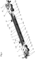
- the platform wagon comprises a base frame 1 with two head pieces 2a, 2b, each with a buffer breast 3a, 3b for the arrangement of buffers 4.
- a longitudinal beam 5 with a central longitudinal axis 7 extends between the two head pieces 2a, 2b.
- a formed support profile 24a, 24b is arranged on the sides of the head pieces 2a, 2b.
- the lower flange 9 is formed by four material stiffeners 12a, 12b, 12c, 12d that run parallel to one another along the central longitudinal axis 7 and are connected to one another at their ends.
- the distance between the material stiffeners 12a, 12b, 12c, 12d is approximately 50% of their extension transverse to the central longitudinal axis 7.
- Both the head pieces 2a, 2b and the longitudinal beam 5 are designed essentially symmetrically to the central longitudinal axis 7.
- the head pieces 2a, 2b therefore taper from the area of the buffer breast 3a, 3b in the direction of the longitudinal beam 5 only from the unweakened area 16a, 16b, so that the full width of the head pieces 2a, 2b is available for the swivel pans 17a, 17b.
- cross arms 18 are provided on each side of the longitudinal beam 5. These serve to accommodate containers and/or superstructures and extend essentially transversely to the central longitudinal axis 7. In further embodiments of the invention not shown, more or fewer cross arms can also be provided.
- the cross beams 18 are arranged on the upper chord 8 and are supported on the lower chord 9 via cross struts 21a, 21b.
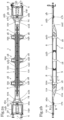
- Fig. 2b shows a view of the base frame 1 from Fig. 2a from the side. It can be seen in this view that the longitudinal beam 5 defines a loading area 6 for the arrangement of containers and/or superstructures. It can also be seen that the longitudinal beam 5 comprises an upper flange 8 and a lower flange 9, which are arranged one above the other and are connected at their ends to one another and to the head pieces 2a, 2b via longitudinal webs 10a, 10b.
- the upper chord 8 and the lower chord 9 are essentially identical in construction.
- the upper chord 8 and the lower chord 9 are arranged one above the other at a distance that essentially corresponds to the width of the longitudinal member 5 transverse to the central longitudinal axis 7, so that the longitudinal member 5 has the shape of an essentially square hollow profile.
- the upper chord 8 and the lower chord 9 are connected to one another at certain points via the K-shaped angle struts 22a, 22b.
- the angle struts 22a, 22b, 22c, 22d are designed in a K-shape such that two of their ends are connected to the upper chord 8 and the lower chord 9.
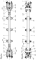
- Fig. 2c shows a view of the underframe 1 according to the invention from above.
- the underframe 1 comprises two head pieces 2a, 2b, each with a buffer breast 3a, 3b and buffers 4 arranged thereon. Between the head pieces 2a, 2b, a longitudinal beam 5 extends symmetrically along a central longitudinal axis 7.
- the longitudinal beam 5 forms a loading surface 6 for supporting containers and/or superstructures, the loading surface 6 being formed by the surface of the upper flange 8.
- the head pieces 2a, 2b themselves also taper from the area of the buffer breast 3a, 3b in the direction of the longitudinal member 5.
- at least two further material recesses 15a, 15b are provided, which also taper in this direction and are essentially triangular in shape.
- the container pins 20a, 20b serve to accommodate containers and/or superstructures.
- the cross arms 18 comprise supports 19a, 19b, which are arranged on the upper chord 8 and extend essentially transversely to the central longitudinal axis 7.
- cross struts 21a, 21b are provided, which support the supports 19a, 19b on the lower chord 9.
- longitudinal web ends 11a, 11b of the longitudinal webs 10a, 10b, 10c, 10d have stabilizing struts.
- material recesses are also provided in the longitudinal webs 10a, 10b, 10c, 10d in order to reduce the weight of these elements.
- the swivel pans 17a, 17b are again arranged in the unweakened area 16a, 16b of the head pieces 2a, 2b.
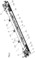
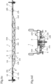
- Fig. 3a shows a schematic view of the underframe 1 according to the invention from the side, with the buffers 4 and the buffer breast 3a visible. Furthermore, the cross struts 21a, 21b for supporting the cross booms 18 are visible. Finally, it is clear from this illustration that the longitudinal webs 10a, 10b run essentially parallel to the central longitudinal axis 7 of the longitudinal beam 5. A lower part 23 is provided on the underside of the head piece 2a. The container pins 20a, 20b are also visible in this illustration.
- the unweakened area 16a, 16b extends transversely to the central longitudinal axis 7.
- the head pieces 2a, 2b taper from the area of the buffer breast 3a, 3b in the direction of the longitudinal beam 5 only from the unweakened area 16a, 16b.
- the unweakened areas 16a, 16b each extend along the central longitudinal axis 7 essentially over about 15% of the length of the head pieces 2a, 2b and are provided slightly offset along the central longitudinal axis 7 in relation to the length of the head pieces 2a, 2b in the direction of the longitudinal beam 5.
- the container pins 20a, 20b serve to accommodate containers and/or superstructures.
- the cross arms 18 comprise supports 19a, 19b, which are arranged on the upper chord 8 and extend essentially transversely to the central longitudinal axis 7.
- cross struts 21a, 21b are provided, which support the supports 19a, 19b on the lower chord 9.
- the upper chord 8 and the lower chord 9 are essentially identical in construction.
- the upper chord 8 and the lower chord 9 are arranged one above the other at a distance that essentially corresponds to the width of the longitudinal beam 5 transverse to the central longitudinal axis 7, so that the longitudinal beam 5 has the shape of an essentially square hollow profile.
- the upper chord 8 and the lower chord 9 are connected to one another at certain points via the angle struts 22a, 22b, 22c, 22d.
Landscapes
- Engineering & Computer Science (AREA)
- Mechanical Engineering (AREA)
- Vibration Dampers (AREA)
- Body Structure For Vehicles (AREA)
- Platform Screen Doors And Railroad Systems (AREA)
- Refuge Islands, Traffic Blockers, Or Guard Fence (AREA)
- Devices Affording Protection Of Roads Or Walls For Sound Insulation (AREA)
- Rod-Shaped Construction Members (AREA)
Priority Applications (2)
| Application Number | Priority Date | Filing Date | Title |
|---|---|---|---|
| SI201830404T SI3630573T2 (sl) | 2017-05-31 | 2018-05-29 | Podvozje za voziček |
| PL18728128.2T PL3630573T5 (pl) | 2017-05-31 | 2018-05-29 | Podwozie do wózka platformowego |
Applications Claiming Priority (2)
| Application Number | Priority Date | Filing Date | Title |
|---|---|---|---|
| ATA50453/2017A AT520110B1 (de) | 2017-05-31 | 2017-05-31 | Untergestell für einen Plattformwagen |
| PCT/EP2018/064078 WO2018219955A1 (de) | 2017-05-31 | 2018-05-29 | Untergestell für einen plattformwagen |
Publications (3)
| Publication Number | Publication Date |
|---|---|
| EP3630573A1 EP3630573A1 (de) | 2020-04-08 |
| EP3630573B1 EP3630573B1 (de) | 2021-06-23 |
| EP3630573B2 true EP3630573B2 (de) | 2024-07-03 |
Family
ID=62455494
Family Applications (1)
| Application Number | Title | Priority Date | Filing Date |
|---|---|---|---|
| EP18728128.2A Active EP3630573B2 (de) | 2017-05-31 | 2018-05-29 | Untergestell für einen plattformwagen |
Country Status (8)
| Country | Link |
|---|---|
| EP (1) | EP3630573B2 (pl) |
| CN (1) | CN111032474B (pl) |
| AT (1) | AT520110B1 (pl) |
| HU (1) | HUE055723T2 (pl) |
| PL (1) | PL3630573T5 (pl) |
| RU (1) | RU2759684C2 (pl) |
| SI (1) | SI3630573T2 (pl) |
| WO (1) | WO2018219955A1 (pl) |
Families Citing this family (9)
| Publication number | Priority date | Publication date | Assignee | Title |
|---|---|---|---|---|
| AT520110B1 (de) | 2017-05-31 | 2019-08-15 | Rail Cargo Wagon Austria Gmbh | Untergestell für einen Plattformwagen |
| DE102019105689B3 (de) | 2019-03-06 | 2020-06-04 | Deutsche Bahn Ag | Untergestell eines Schienenfahrzeuges |
| DE102019105686B3 (de) | 2019-03-06 | 2020-04-16 | Deutsche Bahn Ag | Untergestell eines Schienenfahrzeuges |
| EP3708453B1 (de) * | 2019-03-15 | 2022-10-12 | Schweizerische Bundesbahnen SBB | Untergestell für fahrzeuge und fahrzeug |
| DE102020119526A1 (de) | 2020-07-23 | 2022-01-27 | Deutsche Bahn Aktiengesellschaft | Untergestell eines schienenfahrzeuges |
| DE102020134258A1 (de) | 2020-12-18 | 2022-06-23 | Deutsche Bahn Aktiengesellschaft | Untergestell eines schienenfahrzeuges |
| CN115123330A (zh) * | 2021-03-24 | 2022-09-30 | 中车山东机车车辆有限公司 | 车体底架及车辆 |
| HRP20260334T1 (hr) * | 2022-08-05 | 2026-04-24 | Cgl | Konstrukcija vagona za prijevoz kontejnera |
| FR3138640A1 (fr) * | 2022-08-05 | 2024-02-09 | Cgl | Structure de wagon pour le transport de conteneurs |
Citations (1)
| Publication number | Priority date | Publication date | Assignee | Title |
|---|---|---|---|---|
| CN104057968A (zh) † | 2014-06-25 | 2014-09-24 | 齐齐哈尔轨道交通装备有限责任公司 | 一种集装箱平车的车架 |
Family Cites Families (27)
| Publication number | Priority date | Publication date | Assignee | Title |
|---|---|---|---|---|
| US1038753A (en) | 1911-06-16 | 1912-09-17 | Locomotive Tender Frame Company | Cast-steel underframe for cars. |
| US1078310A (en) * | 1912-08-14 | 1913-11-11 | American Car & Foundry Co | Underframe. |
| US1097800A (en) * | 1912-09-12 | 1914-05-26 | Bettendorf Co | Underframe for cars. |
| US1078312A (en) | 1912-11-19 | 1913-11-11 | American Car & Foundry Co | Cast end frame. |
| US1659361A (en) | 1927-01-12 | 1928-02-14 | Ohio Steel Foundry Co | Cast-steel tender frame |
| DE1233002B (de) * | 1960-12-08 | 1967-01-26 | Pullman Inc | Auf der Ladeflaeche eines Eisenbahnplattformwagens anbringbarer Frachtbehaelter-Traegerrahmen |
| DE1530165C3 (de) * | 1965-11-06 | 1981-02-05 | Waggonfabrik Talbot, 5100 Aachen | Untergestell für Schienenfahrzeuge mit einem Stoßbalken |
| DE1919179A1 (de) * | 1969-04-16 | 1970-10-22 | Rheinstahl Siegener Eisenbahnb | Untergestell fuer Schienenfahrzeuge |
| DE2903249C3 (de) | 1979-01-29 | 1982-02-04 | Ringfeder Gmbh, 4150 Krefeld | Kopfträger für Seitenpuffer, insbesondere für Schienenfahrzeuge |
| AT394531B (de) * | 1990-01-19 | 1992-04-27 | Jenbacher Werke Ag | Schienenfahrzeug, insbesondere zweiachsiger gueterwagen |
| GB2283219B (en) * | 1993-10-27 | 1997-03-19 | Transtech Ltd Oy | Railway car for transporting trailers |
| DE4440425A1 (de) | 1994-11-07 | 1996-05-09 | Goerlitz Waggonbau Gmbh | Untergestell für Schienenfahrzeuge |
| CN1189426A (zh) * | 1997-01-28 | 1998-08-05 | 约翰斯汤美国公司 | 具有料桶的铁路敞车 |
| DE19805429A1 (de) | 1998-02-11 | 1999-08-12 | Elze Waggonbau Gmbh & Co Kg | Behältertragwagen zum Transport von Containern oder Wechselbehältern auf dem Eisenbahnnetz |
| FR2802163B1 (fr) | 1999-12-10 | 2002-02-08 | Arbel Fauvet Rail Sa | Bogie pour une utilisation ferroviaire et wagon pourvu du dit bogie |
| RU96080U1 (ru) * | 2009-08-07 | 2010-07-20 | ОАО "Завод металлоконструкций" | Железнодорожная платформа для перевозки крупнотоннажных контейнеров |
| CN102079314B (zh) | 2010-12-23 | 2012-11-14 | 南车二七车辆有限公司 | 一种适应泰国米轨铁路运行的增载型集装箱平车车体 |
| CN201907519U (zh) * | 2011-01-10 | 2011-07-27 | 南车株洲电力机车有限公司 | 一种中低速磁浮列车悬浮架纵梁 |
| RU108014U1 (ru) * | 2011-03-28 | 2011-09-10 | Афст Эдвансд Фрайт Кар Текнолоджи Лимитед | Рама вагона-платформы |
| DE102012102808A1 (de) * | 2012-03-30 | 2013-10-02 | Demag Cranes & Components Gmbh | Kran, insbesondere Brückenkran oder Portalkran, mit mindestens einem Kranträger |
| JP5931548B2 (ja) * | 2012-04-02 | 2016-06-08 | 川崎重工業株式会社 | 鉄道車両 |
| AT514613B1 (de) | 2013-08-14 | 2015-10-15 | Peter Dipl Ing Wanek-Pusset | Wagenrahmen für einen Containertragwagen und Containertragwagen |
| CN104670252A (zh) * | 2013-12-01 | 2015-06-03 | 太原轨道交通装备有限责任公司 | 低重心集装箱平车 |
| CN204055786U (zh) * | 2014-07-23 | 2014-12-31 | 南车眉山车辆有限公司 | 一种铁路集装箱专用平车 |
| CN105460037B (zh) * | 2015-12-25 | 2018-05-25 | 中车长江车辆有限公司 | 一种平车车体 |
| DE202016104134U1 (de) * | 2016-07-27 | 2016-09-19 | Wbn Waggonbau Niesky Gmbh | Untergestell eines Schienenfahrzeuges |
| AT520110B1 (de) | 2017-05-31 | 2019-08-15 | Rail Cargo Wagon Austria Gmbh | Untergestell für einen Plattformwagen |
-
2017
- 2017-05-31 AT ATA50453/2017A patent/AT520110B1/de active
-
2018
- 2018-05-29 EP EP18728128.2A patent/EP3630573B2/de active Active
- 2018-05-29 WO PCT/EP2018/064078 patent/WO2018219955A1/de not_active Ceased
- 2018-05-29 CN CN201880036686.6A patent/CN111032474B/zh active Active
- 2018-05-29 PL PL18728128.2T patent/PL3630573T5/pl unknown
- 2018-05-29 HU HUE18728128A patent/HUE055723T2/hu unknown
- 2018-05-29 SI SI201830404T patent/SI3630573T2/sl unknown
- 2018-05-29 RU RU2019143707A patent/RU2759684C2/ru active
Patent Citations (1)
| Publication number | Priority date | Publication date | Assignee | Title |
|---|---|---|---|---|
| CN104057968A (zh) † | 2014-06-25 | 2014-09-24 | 齐齐哈尔轨道交通装备有限责任公司 | 一种集装箱平车的车架 |
Also Published As
| Publication number | Publication date |
|---|---|
| HUE055723T2 (hu) | 2021-12-28 |
| CN111032474A (zh) | 2020-04-17 |
| RU2019143707A (ru) | 2021-06-30 |
| RU2019143707A3 (pl) | 2021-09-08 |
| SI3630573T1 (sl) | 2021-11-30 |
| RU2759684C2 (ru) | 2021-11-16 |
| CN111032474B (zh) | 2022-03-25 |
| PL3630573T3 (pl) | 2021-12-20 |
| SI3630573T2 (sl) | 2025-03-31 |
| AT520110A1 (de) | 2019-01-15 |
| PL3630573T5 (pl) | 2024-10-28 |
| WO2018219955A1 (de) | 2018-12-06 |
| AT520110B1 (de) | 2019-08-15 |
| EP3630573B1 (de) | 2021-06-23 |
| EP3630573A1 (de) | 2020-04-08 |
Similar Documents
| Publication | Publication Date | Title |
|---|---|---|
| EP3630573B2 (de) | Untergestell für einen plattformwagen | |
| DE4208700C2 (de) | Vorbaukonstruktion für Fahrzeuge | |
| DE2702243C2 (pl) | ||
| EP3114011B1 (de) | Versteifungsstruktur eines fahrzeugs in form eines schubfelds | |
| DE602004004373T2 (de) | Sattelaufliegerrahmen und -radaufhängung | |
| DE2944289A1 (de) | Hebefahrzeug | |
| AT515824A1 (de) | Kranträger für einen Kran | |
| DE10126234B4 (de) | Aufbaustruktur für ein Kraftfahrzeug mit zusammengesetzten Trägern | |
| WO2021156780A1 (de) | Untergestell für plattformwagen sowie plattformwagen | |
| EP3093220B1 (de) | Expandierbarer fahrzeuganhänger | |
| EP2766245B1 (de) | Hilfsrahmen für kraftfahrzeuge | |
| DE102016111308B4 (de) | Fahrgestellanordnung und Landfahrzeug | |
| DE19750981C2 (de) | Rahmen für Kraftfahrzeuge | |
| DE202021100307U1 (de) | Tragvorrichtung und Taschenwagen | |
| DE102005045295B4 (de) | Fahrschemel für ein Kraftfahrzeug | |
| EP4038008B1 (de) | Träger für eine laufkatze und flurfreie transporteinrichtung mit einem solchen träger | |
| DE1580385C3 (de) | Untergestell für ein Hub- und Förderfahrzeug | |
| EP0111824B1 (de) | Absetzkipper-Aufbau für Lastwagen | |
| EP4178699B1 (de) | Fachwerkschiene, sowie achterbahnanordnung mit derselben | |
| DE975378C (de) | Niederrahmen fuer Kraftfahrzeuge, insbesondere Kraftomnibusse | |
| DE2618191A1 (de) | Tragrahmen von lastfahrzeugen, insbesondere anhaengern | |
| EP3415397A1 (de) | Schienenfahrzeug mit sicherheitsfahrerkabine | |
| DE964836C (de) | Fahrgestell fuer Kraftfahrzeuge, insbesondere fuer Lastkraftfahrzeuge | |
| DE723374C (de) | Verwindungsfaehiger Wagen fuer Lasten mit einem Tragrahmen aus Holz | |
| DE29814630U1 (de) | Nutzfahrzeug mit einem Ladekran und einer Wechselbrücke |
Legal Events
| Date | Code | Title | Description |
|---|---|---|---|
| STAA | Information on the status of an ep patent application or granted ep patent |
Free format text: STATUS: UNKNOWN |
|
| STAA | Information on the status of an ep patent application or granted ep patent |
Free format text: STATUS: THE INTERNATIONAL PUBLICATION HAS BEEN MADE |
|
| PUAI | Public reference made under article 153(3) epc to a published international application that has entered the european phase |
Free format text: ORIGINAL CODE: 0009012 |
|
| STAA | Information on the status of an ep patent application or granted ep patent |
Free format text: STATUS: REQUEST FOR EXAMINATION WAS MADE |
|
| 17P | Request for examination filed |
Effective date: 20191126 |
|
| AK | Designated contracting states |
Kind code of ref document: A1 Designated state(s): AL AT BE BG CH CY CZ DE DK EE ES FI FR GB GR HR HU IE IS IT LI LT LU LV MC MK MT NL NO PL PT RO RS SE SI SK SM TR |
|
| AX | Request for extension of the european patent |
Extension state: BA ME |
|
| DAV | Request for validation of the european patent (deleted) | ||
| DAX | Request for extension of the european patent (deleted) | ||
| GRAP | Despatch of communication of intention to grant a patent |
Free format text: ORIGINAL CODE: EPIDOSNIGR1 |
|
| STAA | Information on the status of an ep patent application or granted ep patent |
Free format text: STATUS: GRANT OF PATENT IS INTENDED |
|
| INTG | Intention to grant announced |
Effective date: 20210122 |
|
| GRAS | Grant fee paid |
Free format text: ORIGINAL CODE: EPIDOSNIGR3 |
|
| GRAA | (expected) grant |
Free format text: ORIGINAL CODE: 0009210 |
|
| STAA | Information on the status of an ep patent application or granted ep patent |
Free format text: STATUS: THE PATENT HAS BEEN GRANTED |
|
| AK | Designated contracting states |
Kind code of ref document: B1 Designated state(s): AL AT BE BG CH CY CZ DE DK EE ES FI FR GB GR HR HU IE IS IT LI LT LU LV MC MK MT NL NO PL PT RO RS SE SI SK SM TR |
|
| REG | Reference to a national code |
Ref country code: GB Ref legal event code: FG4D Free format text: NOT ENGLISH |
|
| REG | Reference to a national code |
Ref country code: CH Ref legal event code: EP |
|
| REG | Reference to a national code |
Ref country code: DE Ref legal event code: R096 Ref document number: 502018005832 Country of ref document: DE Ref country code: AT Ref legal event code: REF Ref document number: 1404069 Country of ref document: AT Kind code of ref document: T Effective date: 20210715 |
|
| REG | Reference to a national code |
Ref country code: IE Ref legal event code: FG4D Free format text: LANGUAGE OF EP DOCUMENT: GERMAN |
|
| REG | Reference to a national code |
Ref country code: SE Ref legal event code: TRGR |
|
| REG | Reference to a national code |
Ref country code: RO Ref legal event code: EPE |
|
| REG | Reference to a national code |
Ref country code: LT Ref legal event code: MG9D |
|
| REG | Reference to a national code |
Ref country code: SK Ref legal event code: T3 Ref document number: E 38043 Country of ref document: SK |
|
| PG25 | Lapsed in a contracting state [announced via postgrant information from national office to epo] |
Ref country code: HR Free format text: LAPSE BECAUSE OF FAILURE TO SUBMIT A TRANSLATION OF THE DESCRIPTION OR TO PAY THE FEE WITHIN THE PRESCRIBED TIME-LIMIT Effective date: 20210623 Ref country code: LT Free format text: LAPSE BECAUSE OF FAILURE TO SUBMIT A TRANSLATION OF THE DESCRIPTION OR TO PAY THE FEE WITHIN THE PRESCRIBED TIME-LIMIT Effective date: 20210623 Ref country code: FI Free format text: LAPSE BECAUSE OF FAILURE TO SUBMIT A TRANSLATION OF THE DESCRIPTION OR TO PAY THE FEE WITHIN THE PRESCRIBED TIME-LIMIT Effective date: 20210623 |
|
| PG25 | Lapsed in a contracting state [announced via postgrant information from national office to epo] |
Ref country code: RS Free format text: LAPSE BECAUSE OF FAILURE TO SUBMIT A TRANSLATION OF THE DESCRIPTION OR TO PAY THE FEE WITHIN THE PRESCRIBED TIME-LIMIT Effective date: 20210623 Ref country code: NO Free format text: LAPSE BECAUSE OF FAILURE TO SUBMIT A TRANSLATION OF THE DESCRIPTION OR TO PAY THE FEE WITHIN THE PRESCRIBED TIME-LIMIT Effective date: 20210923 Ref country code: LV Free format text: LAPSE BECAUSE OF FAILURE TO SUBMIT A TRANSLATION OF THE DESCRIPTION OR TO PAY THE FEE WITHIN THE PRESCRIBED TIME-LIMIT Effective date: 20210623 Ref country code: GR Free format text: LAPSE BECAUSE OF FAILURE TO SUBMIT A TRANSLATION OF THE DESCRIPTION OR TO PAY THE FEE WITHIN THE PRESCRIBED TIME-LIMIT Effective date: 20210924 |
|
| REG | Reference to a national code |
Ref country code: NL Ref legal event code: MP Effective date: 20210623 |
|
| REG | Reference to a national code |
Ref country code: HU Ref legal event code: AG4A Ref document number: E055723 Country of ref document: HU |
|
| PG25 | Lapsed in a contracting state [announced via postgrant information from national office to epo] |
Ref country code: EE Free format text: LAPSE BECAUSE OF FAILURE TO SUBMIT A TRANSLATION OF THE DESCRIPTION OR TO PAY THE FEE WITHIN THE PRESCRIBED TIME-LIMIT Effective date: 20210623 Ref country code: ES Free format text: LAPSE BECAUSE OF FAILURE TO SUBMIT A TRANSLATION OF THE DESCRIPTION OR TO PAY THE FEE WITHIN THE PRESCRIBED TIME-LIMIT Effective date: 20210623 Ref country code: SM Free format text: LAPSE BECAUSE OF FAILURE TO SUBMIT A TRANSLATION OF THE DESCRIPTION OR TO PAY THE FEE WITHIN THE PRESCRIBED TIME-LIMIT Effective date: 20210623 Ref country code: PT Free format text: LAPSE BECAUSE OF FAILURE TO SUBMIT A TRANSLATION OF THE DESCRIPTION OR TO PAY THE FEE WITHIN THE PRESCRIBED TIME-LIMIT Effective date: 20211025 Ref country code: NL Free format text: LAPSE BECAUSE OF FAILURE TO SUBMIT A TRANSLATION OF THE DESCRIPTION OR TO PAY THE FEE WITHIN THE PRESCRIBED TIME-LIMIT Effective date: 20210623 |
|
| REG | Reference to a national code |
Ref country code: DE Ref legal event code: R026 Ref document number: 502018005832 Country of ref document: DE |
|
| PLBI | Opposition filed |
Free format text: ORIGINAL CODE: 0009260 |
|
| PLAX | Notice of opposition and request to file observation + time limit sent |
Free format text: ORIGINAL CODE: EPIDOSNOBS2 |
|
| 26 | Opposition filed |
Opponent name: VTG RAIL EUROPE GMBH Effective date: 20220323 Opponent name: DEUTSCHE BAHN AG Effective date: 20220321 |
|
| PG25 | Lapsed in a contracting state [announced via postgrant information from national office to epo] |
Ref country code: DK Free format text: LAPSE BECAUSE OF FAILURE TO SUBMIT A TRANSLATION OF THE DESCRIPTION OR TO PAY THE FEE WITHIN THE PRESCRIBED TIME-LIMIT Effective date: 20210623 |
|
| PG25 | Lapsed in a contracting state [announced via postgrant information from national office to epo] |
Ref country code: AL Free format text: LAPSE BECAUSE OF FAILURE TO SUBMIT A TRANSLATION OF THE DESCRIPTION OR TO PAY THE FEE WITHIN THE PRESCRIBED TIME-LIMIT Effective date: 20210623 |
|
| PLBB | Reply of patent proprietor to notice(s) of opposition received |
Free format text: ORIGINAL CODE: EPIDOSNOBS3 |
|
| REG | Reference to a national code |
Ref country code: BE Ref legal event code: MM Effective date: 20220531 |
|
| GBPC | Gb: european patent ceased through non-payment of renewal fee |
Effective date: 20220529 |
|
| PG25 | Lapsed in a contracting state [announced via postgrant information from national office to epo] |
Ref country code: MC Free format text: LAPSE BECAUSE OF FAILURE TO SUBMIT A TRANSLATION OF THE DESCRIPTION OR TO PAY THE FEE WITHIN THE PRESCRIBED TIME-LIMIT Effective date: 20210623 Ref country code: LU Free format text: LAPSE BECAUSE OF NON-PAYMENT OF DUE FEES Effective date: 20220529 |
|
| PG25 | Lapsed in a contracting state [announced via postgrant information from national office to epo] |
Ref country code: IE Free format text: LAPSE BECAUSE OF NON-PAYMENT OF DUE FEES Effective date: 20220529 |
|
| PG25 | Lapsed in a contracting state [announced via postgrant information from national office to epo] |
Ref country code: GB Free format text: LAPSE BECAUSE OF NON-PAYMENT OF DUE FEES Effective date: 20220529 Ref country code: BE Free format text: LAPSE BECAUSE OF NON-PAYMENT OF DUE FEES Effective date: 20220531 |
|
| P01 | Opt-out of the competence of the unified patent court (upc) registered |
Effective date: 20230516 |
|
| PG25 | Lapsed in a contracting state [announced via postgrant information from national office to epo] |
Ref country code: MK Free format text: LAPSE BECAUSE OF FAILURE TO SUBMIT A TRANSLATION OF THE DESCRIPTION OR TO PAY THE FEE WITHIN THE PRESCRIBED TIME-LIMIT Effective date: 20210623 Ref country code: CY Free format text: LAPSE BECAUSE OF FAILURE TO SUBMIT A TRANSLATION OF THE DESCRIPTION OR TO PAY THE FEE WITHIN THE PRESCRIBED TIME-LIMIT Effective date: 20210623 |
|
| PUAH | Patent maintained in amended form |
Free format text: ORIGINAL CODE: 0009272 |
|
| STAA | Information on the status of an ep patent application or granted ep patent |
Free format text: STATUS: PATENT MAINTAINED AS AMENDED |
|
| 27A | Patent maintained in amended form |
Effective date: 20240703 |
|
| AK | Designated contracting states |
Kind code of ref document: B2 Designated state(s): AL AT BE BG CH CY CZ DE DK EE ES FI FR GB GR HR HU IE IS IT LI LT LU LV MC MK MT NL NO PL PT RO RS SE SI SK SM TR |
|
| REG | Reference to a national code |
Ref country code: DE Ref legal event code: R102 Ref document number: 502018005832 Country of ref document: DE |
|
| REG | Reference to a national code |
Ref country code: SE Ref legal event code: RPEO |
|
| PG25 | Lapsed in a contracting state [announced via postgrant information from national office to epo] |
Ref country code: MT Free format text: LAPSE BECAUSE OF FAILURE TO SUBMIT A TRANSLATION OF THE DESCRIPTION OR TO PAY THE FEE WITHIN THE PRESCRIBED TIME-LIMIT Effective date: 20210623 |
|
| REG | Reference to a national code |
Ref country code: SK Ref legal event code: T5 Ref document number: E 38043 Country of ref document: SK |
|
| REG | Reference to a national code |
Ref country code: SK Ref legal event code: T4 Ref document number: E 38043 Country of ref document: SK |
|
| PGFP | Annual fee paid to national office [announced via postgrant information from national office to epo] |
Ref country code: PL Payment date: 20250312 Year of fee payment: 8 |
|
| PGFP | Annual fee paid to national office [announced via postgrant information from national office to epo] |
Ref country code: DE Payment date: 20250508 Year of fee payment: 8 |
|
| PGFP | Annual fee paid to national office [announced via postgrant information from national office to epo] |
Ref country code: HU Payment date: 20250523 Year of fee payment: 8 |
|
| PGFP | Annual fee paid to national office [announced via postgrant information from national office to epo] |
Ref country code: IT Payment date: 20250527 Year of fee payment: 8 |
|
| PGFP | Annual fee paid to national office [announced via postgrant information from national office to epo] |
Ref country code: FR Payment date: 20250528 Year of fee payment: 8 |
|
| PGFP | Annual fee paid to national office [announced via postgrant information from national office to epo] |
Ref country code: BG Payment date: 20250521 Year of fee payment: 8 |
|
| PGFP | Annual fee paid to national office [announced via postgrant information from national office to epo] |
Ref country code: CH Payment date: 20250601 Year of fee payment: 8 |
|
| PGFP | Annual fee paid to national office [announced via postgrant information from national office to epo] |
Ref country code: AT Payment date: 20250506 Year of fee payment: 8 Ref country code: RO Payment date: 20250522 Year of fee payment: 8 |
|
| PGFP | Annual fee paid to national office [announced via postgrant information from national office to epo] |
Ref country code: TR Payment date: 20250521 Year of fee payment: 8 Ref country code: SK Payment date: 20250519 Year of fee payment: 8 |
|
| PGFP | Annual fee paid to national office [announced via postgrant information from national office to epo] |
Ref country code: CZ Payment date: 20250520 Year of fee payment: 8 |
|
| PGFP | Annual fee paid to national office [announced via postgrant information from national office to epo] |
Ref country code: SI Payment date: 20250515 Year of fee payment: 8 Ref country code: SE Payment date: 20250521 Year of fee payment: 8 |