EP3605644A1 - Unterbringungsvorrichtung - Google Patents
Unterbringungsvorrichtung Download PDFInfo
- Publication number
- EP3605644A1 EP3605644A1 EP18771304.5A EP18771304A EP3605644A1 EP 3605644 A1 EP3605644 A1 EP 3605644A1 EP 18771304 A EP18771304 A EP 18771304A EP 3605644 A1 EP3605644 A1 EP 3605644A1
- Authority
- EP
- European Patent Office
- Prior art keywords
- connector
- storage battery
- lid
- housing device
- opening
- Prior art date
- Legal status (The legal status is an assumption and is not a legal conclusion. Google has not performed a legal analysis and makes no representation as to the accuracy of the status listed.)
- Granted
Links
- 230000004308 accommodation Effects 0.000 title 1
- 230000007246 mechanism Effects 0.000 claims description 36
- 238000001514 detection method Methods 0.000 claims description 31
- 230000005540 biological transmission Effects 0.000 claims description 18
- 238000003780 insertion Methods 0.000 claims description 12
- 230000037431 insertion Effects 0.000 claims description 12
- 230000005484 gravity Effects 0.000 claims description 5
- 238000004891 communication Methods 0.000 description 14
- 230000008859 change Effects 0.000 description 10
- 238000000034 method Methods 0.000 description 8
- 230000008569 process Effects 0.000 description 3
- 230000005611 electricity Effects 0.000 description 2
- 230000006870 function Effects 0.000 description 2
- 230000009471 action Effects 0.000 description 1
- 230000007423 decrease Effects 0.000 description 1
- 230000010365 information processing Effects 0.000 description 1
- 238000009434 installation Methods 0.000 description 1
- 238000010295 mobile communication Methods 0.000 description 1
- 230000002093 peripheral effect Effects 0.000 description 1
- 238000000926 separation method Methods 0.000 description 1
- 238000013519 translation Methods 0.000 description 1
Images


Classifications
-
- B—PERFORMING OPERATIONS; TRANSPORTING
- B60—VEHICLES IN GENERAL
- B60L—PROPULSION OF ELECTRICALLY-PROPELLED VEHICLES; SUPPLYING ELECTRIC POWER FOR AUXILIARY EQUIPMENT OF ELECTRICALLY-PROPELLED VEHICLES; ELECTRODYNAMIC BRAKE SYSTEMS FOR VEHICLES IN GENERAL; MAGNETIC SUSPENSION OR LEVITATION FOR VEHICLES; MONITORING OPERATING VARIABLES OF ELECTRICALLY-PROPELLED VEHICLES; ELECTRIC SAFETY DEVICES FOR ELECTRICALLY-PROPELLED VEHICLES
- B60L53/00—Methods of charging batteries, specially adapted for electric vehicles; Charging stations or on-board charging equipment therefor; Exchange of energy storage elements in electric vehicles
- B60L53/10—Methods of charging batteries, specially adapted for electric vehicles; Charging stations or on-board charging equipment therefor; Exchange of energy storage elements in electric vehicles characterised by the energy transfer between the charging station and the vehicle
- B60L53/14—Conductive energy transfer
- B60L53/16—Connectors, e.g. plugs or sockets, specially adapted for charging electric vehicles
-
- B—PERFORMING OPERATIONS; TRANSPORTING
- B60—VEHICLES IN GENERAL
- B60L—PROPULSION OF ELECTRICALLY-PROPELLED VEHICLES; SUPPLYING ELECTRIC POWER FOR AUXILIARY EQUIPMENT OF ELECTRICALLY-PROPELLED VEHICLES; ELECTRODYNAMIC BRAKE SYSTEMS FOR VEHICLES IN GENERAL; MAGNETIC SUSPENSION OR LEVITATION FOR VEHICLES; MONITORING OPERATING VARIABLES OF ELECTRICALLY-PROPELLED VEHICLES; ELECTRIC SAFETY DEVICES FOR ELECTRICALLY-PROPELLED VEHICLES
- B60L53/00—Methods of charging batteries, specially adapted for electric vehicles; Charging stations or on-board charging equipment therefor; Exchange of energy storage elements in electric vehicles
- B60L53/80—Exchanging energy storage elements, e.g. removable batteries
-
- B—PERFORMING OPERATIONS; TRANSPORTING
- B62—LAND VEHICLES FOR TRAVELLING OTHERWISE THAN ON RAILS
- B62J—CYCLE SADDLES OR SEATS; AUXILIARY DEVICES OR ACCESSORIES SPECIALLY ADAPTED TO CYCLES AND NOT OTHERWISE PROVIDED FOR, e.g. ARTICLE CARRIERS OR CYCLE PROTECTORS
- B62J43/00—Arrangements of batteries
- B62J43/20—Arrangements of batteries characterised by the mounting
-
- F—MECHANICAL ENGINEERING; LIGHTING; HEATING; WEAPONS; BLASTING
- F16—ENGINEERING ELEMENTS AND UNITS; GENERAL MEASURES FOR PRODUCING AND MAINTAINING EFFECTIVE FUNCTIONING OF MACHINES OR INSTALLATIONS; THERMAL INSULATION IN GENERAL
- F16H—GEARING
- F16H21/00—Gearings comprising primarily only links or levers, with or without slides
- F16H21/10—Gearings comprising primarily only links or levers, with or without slides all movement being in, or parallel to, a single plane
- F16H21/16—Gearings comprising primarily only links or levers, with or without slides all movement being in, or parallel to, a single plane for interconverting rotary motion and reciprocating motion
- F16H21/18—Crank gearings; Eccentric gearings
- F16H21/22—Crank gearings; Eccentric gearings with one connecting-rod and one guided slide to each crank or eccentric
- F16H21/28—Crank gearings; Eccentric gearings with one connecting-rod and one guided slide to each crank or eccentric with cams or additional guides
-
- H—ELECTRICITY
- H01—ELECTRIC ELEMENTS
- H01M—PROCESSES OR MEANS, e.g. BATTERIES, FOR THE DIRECT CONVERSION OF CHEMICAL ENERGY INTO ELECTRICAL ENERGY
- H01M10/00—Secondary cells; Manufacture thereof
- H01M10/42—Methods or arrangements for servicing or maintenance of secondary cells or secondary half-cells
- H01M10/44—Methods for charging or discharging
-
- H—ELECTRICITY
- H01—ELECTRIC ELEMENTS
- H01M—PROCESSES OR MEANS, e.g. BATTERIES, FOR THE DIRECT CONVERSION OF CHEMICAL ENERGY INTO ELECTRICAL ENERGY
- H01M10/00—Secondary cells; Manufacture thereof
- H01M10/42—Methods or arrangements for servicing or maintenance of secondary cells or secondary half-cells
- H01M10/46—Accumulators structurally combined with charging apparatus
-
- H—ELECTRICITY
- H01—ELECTRIC ELEMENTS
- H01M—PROCESSES OR MEANS, e.g. BATTERIES, FOR THE DIRECT CONVERSION OF CHEMICAL ENERGY INTO ELECTRICAL ENERGY
- H01M50/00—Constructional details or processes of manufacture of the non-active parts of electrochemical cells other than fuel cells, e.g. hybrid cells
- H01M50/20—Mountings; Secondary casings or frames; Racks, modules or packs; Suspension devices; Shock absorbers; Transport or carrying devices; Holders
- H01M50/249—Mountings; Secondary casings or frames; Racks, modules or packs; Suspension devices; Shock absorbers; Transport or carrying devices; Holders specially adapted for aircraft or vehicles, e.g. cars or trains
-
- H—ELECTRICITY
- H01—ELECTRIC ELEMENTS
- H01M—PROCESSES OR MEANS, e.g. BATTERIES, FOR THE DIRECT CONVERSION OF CHEMICAL ENERGY INTO ELECTRICAL ENERGY
- H01M50/00—Constructional details or processes of manufacture of the non-active parts of electrochemical cells other than fuel cells, e.g. hybrid cells
- H01M50/20—Mountings; Secondary casings or frames; Racks, modules or packs; Suspension devices; Shock absorbers; Transport or carrying devices; Holders
- H01M50/271—Lids or covers for the racks or secondary casings
-
- H—ELECTRICITY
- H01—ELECTRIC ELEMENTS
- H01R—ELECTRICALLY-CONDUCTIVE CONNECTIONS; STRUCTURAL ASSOCIATIONS OF A PLURALITY OF MUTUALLY-INSULATED ELECTRICAL CONNECTING ELEMENTS; COUPLING DEVICES; CURRENT COLLECTORS
- H01R9/00—Structural associations of a plurality of mutually-insulated electrical connecting elements, e.g. terminal strips or terminal blocks; Terminals or binding posts mounted upon a base or in a case; Bases therefor
- H01R9/22—Bases, e.g. strip, block, panel
- H01R9/28—Terminal boards
-
- H—ELECTRICITY
- H02—GENERATION; CONVERSION OR DISTRIBUTION OF ELECTRIC POWER
- H02J—CIRCUIT ARRANGEMENTS OR SYSTEMS FOR SUPPLYING OR DISTRIBUTING ELECTRIC POWER; SYSTEMS FOR STORING ELECTRIC ENERGY
- H02J7/00—Circuit arrangements for charging or depolarising batteries or for supplying loads from batteries
- H02J7/0042—Circuit arrangements for charging or depolarising batteries or for supplying loads from batteries characterised by the mechanical construction
- H02J7/0045—Circuit arrangements for charging or depolarising batteries or for supplying loads from batteries characterised by the mechanical construction concerning the insertion or the connection of the batteries
-
- B—PERFORMING OPERATIONS; TRANSPORTING
- B60—VEHICLES IN GENERAL
- B60L—PROPULSION OF ELECTRICALLY-PROPELLED VEHICLES; SUPPLYING ELECTRIC POWER FOR AUXILIARY EQUIPMENT OF ELECTRICALLY-PROPELLED VEHICLES; ELECTRODYNAMIC BRAKE SYSTEMS FOR VEHICLES IN GENERAL; MAGNETIC SUSPENSION OR LEVITATION FOR VEHICLES; MONITORING OPERATING VARIABLES OF ELECTRICALLY-PROPELLED VEHICLES; ELECTRIC SAFETY DEVICES FOR ELECTRICALLY-PROPELLED VEHICLES
- B60L2200/00—Type of vehicles
- B60L2200/12—Bikes
-
- B—PERFORMING OPERATIONS; TRANSPORTING
- B60—VEHICLES IN GENERAL
- B60L—PROPULSION OF ELECTRICALLY-PROPELLED VEHICLES; SUPPLYING ELECTRIC POWER FOR AUXILIARY EQUIPMENT OF ELECTRICALLY-PROPELLED VEHICLES; ELECTRODYNAMIC BRAKE SYSTEMS FOR VEHICLES IN GENERAL; MAGNETIC SUSPENSION OR LEVITATION FOR VEHICLES; MONITORING OPERATING VARIABLES OF ELECTRICALLY-PROPELLED VEHICLES; ELECTRIC SAFETY DEVICES FOR ELECTRICALLY-PROPELLED VEHICLES
- B60L50/00—Electric propulsion with power supplied within the vehicle
- B60L50/50—Electric propulsion with power supplied within the vehicle using propulsion power supplied by batteries or fuel cells
- B60L50/60—Electric propulsion with power supplied within the vehicle using propulsion power supplied by batteries or fuel cells using power supplied by batteries
- B60L50/64—Constructional details of batteries specially adapted for electric vehicles
-
- B—PERFORMING OPERATIONS; TRANSPORTING
- B60—VEHICLES IN GENERAL
- B60Y—INDEXING SCHEME RELATING TO ASPECTS CROSS-CUTTING VEHICLE TECHNOLOGY
- B60Y2200/00—Type of vehicle
- B60Y2200/10—Road Vehicles
- B60Y2200/12—Motorcycles, Trikes; Quads; Scooters
-
- B—PERFORMING OPERATIONS; TRANSPORTING
- B60—VEHICLES IN GENERAL
- B60Y—INDEXING SCHEME RELATING TO ASPECTS CROSS-CUTTING VEHICLE TECHNOLOGY
- B60Y2200/00—Type of vehicle
- B60Y2200/90—Vehicles comprising electric prime movers
- B60Y2200/91—Electric vehicles
-
- H—ELECTRICITY
- H01—ELECTRIC ELEMENTS
- H01M—PROCESSES OR MEANS, e.g. BATTERIES, FOR THE DIRECT CONVERSION OF CHEMICAL ENERGY INTO ELECTRICAL ENERGY
- H01M2220/00—Batteries for particular applications
- H01M2220/20—Batteries in motive systems, e.g. vehicle, ship, plane
-
- H—ELECTRICITY
- H01—ELECTRIC ELEMENTS
- H01M—PROCESSES OR MEANS, e.g. BATTERIES, FOR THE DIRECT CONVERSION OF CHEMICAL ENERGY INTO ELECTRICAL ENERGY
- H01M2220/00—Batteries for particular applications
- H01M2220/30—Batteries in portable systems, e.g. mobile phone, laptop
-
- Y—GENERAL TAGGING OF NEW TECHNOLOGICAL DEVELOPMENTS; GENERAL TAGGING OF CROSS-SECTIONAL TECHNOLOGIES SPANNING OVER SEVERAL SECTIONS OF THE IPC; TECHNICAL SUBJECTS COVERED BY FORMER USPC CROSS-REFERENCE ART COLLECTIONS [XRACs] AND DIGESTS
- Y02—TECHNOLOGIES OR APPLICATIONS FOR MITIGATION OR ADAPTATION AGAINST CLIMATE CHANGE
- Y02E—REDUCTION OF GREENHOUSE GAS [GHG] EMISSIONS, RELATED TO ENERGY GENERATION, TRANSMISSION OR DISTRIBUTION
- Y02E60/00—Enabling technologies; Technologies with a potential or indirect contribution to GHG emissions mitigation
- Y02E60/10—Energy storage using batteries
-
- Y—GENERAL TAGGING OF NEW TECHNOLOGICAL DEVELOPMENTS; GENERAL TAGGING OF CROSS-SECTIONAL TECHNOLOGIES SPANNING OVER SEVERAL SECTIONS OF THE IPC; TECHNICAL SUBJECTS COVERED BY FORMER USPC CROSS-REFERENCE ART COLLECTIONS [XRACs] AND DIGESTS
- Y02—TECHNOLOGIES OR APPLICATIONS FOR MITIGATION OR ADAPTATION AGAINST CLIMATE CHANGE
- Y02T—CLIMATE CHANGE MITIGATION TECHNOLOGIES RELATED TO TRANSPORTATION
- Y02T10/00—Road transport of goods or passengers
- Y02T10/60—Other road transportation technologies with climate change mitigation effect
- Y02T10/70—Energy storage systems for electromobility, e.g. batteries
-
- Y—GENERAL TAGGING OF NEW TECHNOLOGICAL DEVELOPMENTS; GENERAL TAGGING OF CROSS-SECTIONAL TECHNOLOGIES SPANNING OVER SEVERAL SECTIONS OF THE IPC; TECHNICAL SUBJECTS COVERED BY FORMER USPC CROSS-REFERENCE ART COLLECTIONS [XRACs] AND DIGESTS
- Y02—TECHNOLOGIES OR APPLICATIONS FOR MITIGATION OR ADAPTATION AGAINST CLIMATE CHANGE
- Y02T—CLIMATE CHANGE MITIGATION TECHNOLOGIES RELATED TO TRANSPORTATION
- Y02T10/00—Road transport of goods or passengers
- Y02T10/60—Other road transportation technologies with climate change mitigation effect
- Y02T10/7072—Electromobility specific charging systems or methods for batteries, ultracapacitors, supercapacitors or double-layer capacitors
-
- Y—GENERAL TAGGING OF NEW TECHNOLOGICAL DEVELOPMENTS; GENERAL TAGGING OF CROSS-SECTIONAL TECHNOLOGIES SPANNING OVER SEVERAL SECTIONS OF THE IPC; TECHNICAL SUBJECTS COVERED BY FORMER USPC CROSS-REFERENCE ART COLLECTIONS [XRACs] AND DIGESTS
- Y02—TECHNOLOGIES OR APPLICATIONS FOR MITIGATION OR ADAPTATION AGAINST CLIMATE CHANGE
- Y02T—CLIMATE CHANGE MITIGATION TECHNOLOGIES RELATED TO TRANSPORTATION
- Y02T90/00—Enabling technologies or technologies with a potential or indirect contribution to GHG emissions mitigation
- Y02T90/10—Technologies relating to charging of electric vehicles
- Y02T90/12—Electric charging stations
-
- Y—GENERAL TAGGING OF NEW TECHNOLOGICAL DEVELOPMENTS; GENERAL TAGGING OF CROSS-SECTIONAL TECHNOLOGIES SPANNING OVER SEVERAL SECTIONS OF THE IPC; TECHNICAL SUBJECTS COVERED BY FORMER USPC CROSS-REFERENCE ART COLLECTIONS [XRACs] AND DIGESTS
- Y02—TECHNOLOGIES OR APPLICATIONS FOR MITIGATION OR ADAPTATION AGAINST CLIMATE CHANGE
- Y02T—CLIMATE CHANGE MITIGATION TECHNOLOGIES RELATED TO TRANSPORTATION
- Y02T90/00—Enabling technologies or technologies with a potential or indirect contribution to GHG emissions mitigation
- Y02T90/10—Technologies relating to charging of electric vehicles
- Y02T90/14—Plug-in electric vehicles
Definitions
- the present invention relates to a housing device.
- a charging station which houses a storage battery for electric motorcycles and provides a user of an electric motorcycle with a fully-charged storage battery (for example, see Patent Literature 1).
- Patent Literature 1 Japanese Translation of PCT International Application No. 2016-514357
- a mechanism or method that can be used for at least one of connection and disconnection of a connector on a storage battery side and a connector on a charging station side.
- a housing device houses, for example, the storage battery.
- the storage battery may include a first battery.
- the housing device includes, for example, a storage battery holding part which holds the storage battery.
- the housing device includes, for a drive part which (i) moves a second connector that is to be connected to the first connector of the storage battery toward the first connector and/or (ii) moves a second connector that has been connected to the first connector of the storage battery in a direction away from the first connector.
- the housing device may include a casing capable of housing the storage battery.
- an opening having a size available for carrying in or out the storage battery is formed in the casing.
- the casing may include a lid part configured to be capable of opening and closing the opening by at least one of a rotational operation and a sliding operation.
- the storage battery holding part may be arranged on a surface facing an inside of the casing among one or more surfaces of the lid part, In the hosing deivce, the storage battery holding part may define a relative position of the lid part and the storage battery held by the storage battery holding part.
- the drive part may drive the second connector such that (a) the second connector moves toward the first connector as the lid part is closed, and (b) movement of the second connector is ended (i) when the lid part is closed completely or (ii) before the lid part is closed completely.
- the drive part may drive the second connector such that (a) the second connector moves in a direction away from the first connector as the lid part is opened, and (b) movement of the second connector is ended (i) when the lid part is opened completely or (ii) before the lid part is opened completely.
- the drive part may have a power transmission part which converts at least one of (i) force generated by opening and closing the lid part and (ii) gravity acting on the storage battery into a driving force of the drive part.
- the power transmission part may include at least one of one or more cam mechanisms and one or more link mechanisms.
- the housing device may include a connector holding part which holds the second connector.
- the housing device may include a positioning part which is arranged inside the casing and defines a position of the connector holding part while the lid part is closed completely. In the housing device, the positioning part may position the connector holding part such that the first connector and the second connector are connected electrically while the lid part is closed completely.
- the storage battery holding part may include, on a surface facing the connector holding part, an extension member which extends in an insertion direction of the storage battery through the connector holding part.
- the connector holding part may be configured to move translationally in the insertion direction of the storage battery.
- the connector holding part may include, on a surface opposite to a surface facing the storage battery holding part, a link member.
- the link member may include a first link member which includes a first surface contacting the positioning part and a second surface contacting the extension member and is arranged to be rotatable about an axis located near an intersection of the first surface and the second surface.
- the link member may include a second link member having one end fixed to the opposite surface of the connector holding part, and another end coupled rotatably to the first link member.
- the hosing device may include a cam part which is attached to a rotational axis rotated by opening and closing of the lid part.
- the connector holding part may be a follower of the cam part.
- a relative position of the first connector and the second connector may be adjusted by a translational movement of the second connector corresponding to a rotation of the cam part.
- the drive part may move the second connector toward the first connector after the lid part is closed completely. In the housing device, the drive part may move the second connector in a direction away from the first connector after the lid part is opened completely.
- the housing device may include an opening and closing detection part which detects opening and closing of the lid part. In the housing device, the drive part may move the second connector when the opening and closing detection part detects the opening and closing of the lid part.
- the housing device may include a holding detection part which detects that the storage battery holding part holds the storage battery.
- the drive part may move the second connector when the holding detection part detects the holding of the storage battery.
- the storage battery may be a portable storage battery.
- a weight of the portable storage battery may be 3 kg or more.
- the housing device may include a charging part which charges the storage battery through the first connector and the second connector.
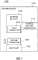
- Fig. 1 schematically illustrates one example of a system configuration of a housing device 100.
- the housing device 100 houses one or more storage batteries 102.
- the storage battery 102 may include a first connector 104.
- the housing device 100 includes a storage battery holding part 110.
- the housing device 100 includes a drive part 120.
- the storage battery holding part 110 may hold the storage battery 102.
- the drive part 120 moves a second connector 106.
- the second connector 106 may be a connector to be connected to the first connector 104.
- the second connector 106 may be a connector already connected to the first connector 104.
- the drive part 120 moves the second connector 106 that is to be connected to the first connector 104 toward the first connector 104.
- the drive part 120 moves the second connector 106 that has been connected to the first connector 104 in a direction away from the first connector 104.
- the user may utilize the mass of the storage battery 102 to connect the first connector 104 and the second connector 106, or the user may firmly push the storage battery 102 to connect the first connector 104 and the second connector 106.
- at least one of the first connector 104 and the second connector 106 may be damaged by the mass of the storage battery 102 or the force applied to the storage battery holding part 110.
- an insertion load and an pull-out load of the first connector 104 and the second connector 106 it may be inconvenience for the user, or an action of the user may contribute to the breakage of the first connector 104 and the second connector 106.
- the first connector 104 and the second connector 106 are connected or separated when the drive part 120 moves the second connector 106.
- the change rate of the relative position of the first connector 104 and the second connector 106 is larger than the change rate of the relative position of the first connector 104 and the storage battery holding part 110.
- the change rate of the relative position of the first connector 104 and the second connector 106 is larger than the change rate of the relative position of the first connector 104 and the storage battery holding part 110.
- the breakage of the first connector 104 or the second connector 106 is suppressed. According to another embodiment, even in a case where the insertion load and/or the pull-out load of the first connector 104 and the second connector 106 are large, the load on the user is reduced. As a result, the convenience of the user is improved. In addition, it is possible to prevent the user from forcibly inserting or pulling out the storage battery 102.
- FIG. 2 schematically illustrates one example of an appearance of the battery station 200.
- the battery station 200 includes one or more housing boxes 210.
- the mobile battery 10 is housed in each of the one or more housing boxes 210.
- the mobile battery 10 may be a portable storage battery.
- the type of the storage battery is not limited particularly.
- any type of secondary battery can be used.
- the weight of the mobile battery 10 may be 1 kg or more, 3 kg or more, 5 kg or more, or 10 kg or more.
- the weight of the mobile battery 10 is not limited thereto.
- the mobile battery 10 includes a connector 12.
- the connector 12 may include at least one of a power line and a communication line.
- the connector 12 may be a connector for wired connection or may be a connector for wireless connection.
- the connector 12 is preferably arranged in a groove or a recess part formed on one surface (for example, a bottom surface) of the mobile battery 10. Accordingly, it is possible to suppress the breakage of the connector 12.
- the mobile battery 10 may be one example of a storage battery.
- the connector 12 may be one example of a first connector.
- Fig. 3 schematically illustrates one example of an internal configuration of a housing box 210.
- Fig. 3 may be one example of a side section of the housing box 210 in a state where the lid of the housing box 210 is closed.
- Fig. 3 includes (i) a schematic view of a side section of the housing box 210 in a state 302 where the connector 12 of the housed mobile battery 10 is not connected electrically and (ii) a schematic view of a side section of the housing box 210 in a state 304 where the connector 12 of the housed mobile battery 10 is connected electrically.
- the state of the housing box 210 is shifted from the state 302 to the state 304.
- the state of the housing box 210 is shifted from the state 304 to the state 302.
- the housing box 210 includes a housing 320, a battery holder 330, a connector 340, a connector holder 342, and a connection control part 350.
- the housing 320 includes a lid 322, a hinge 324, and a position adjusting member 326.
- the connection control part 350 includes a drive member 352 and a detection member 354.
- the housing 320 may be one example of a casing.
- the lid 322 may be one example of a lid part.
- the position adjusting member 326 may be one example of a positioning part.
- the battery holder 330 may be one example of a storage battery holding part.
- the connector 340 may be one example of a second connector.
- the connector holder 342 may be one example of a connector holding part.
- the connection control part 350 may be one example of a drive part.
- the drive member 352 may be one example of a power transmission part.
- the detection member 354 may be one example of an opening and closing detection part and a holding detection part.
- the housing 320 houses the mobile battery 10 therein.
- the housing 320 may store a single mobile battery 10 or may store a plurality of mobile batteries 10.
- an opening 321 having a size available for carrying in or out the mobile battery 10 is formed in the housing 320.
- the lid 322 is configured to be capable of opening and closing the opening 321 by a rotational operation.
- the lid 322 is attached to the housing 320 by the hinge 324 to cover the opening 321.
- the lid 322 may be configured to be capable of opening and closing the opening 321 by a sliding operation.
- the position adjusting member 326 is arranged inside the housing 320 and defines the position of the connector holder 342.
- the position adjusting member 326 defines the position of the connector holder 342 in a state where the lid 322 is closed completely.
- the position adjusting member 326 may position the connector holder 342 such that the connector 12 and the connector 340 are connected electrically in a state where the lid 322 is closed completely.
- the position adjusting member 326 defines the installation surface of the connection control part 350. Accordingly, for example, the position adjusting member 326 can define the height of the connector holder 342 in a case where the connection control part 350 pushes up the connector holder 342. As a result, for example, the connection control part 350 can connect the connector 340 to the connector 12 while suppressing the breakage of at least one of the connector 12 and the connector 340.
- the position adjusting member 326 includes an elastic member or a buffer member and may absorb a part of an impact generated when the connector 340 is connected to the connector 12.
- the battery holder 330 holds the mobile battery 10.
- the battery holder 330 is arranged on a surface (referred to as the inside surface of the lid 322, the inner surface of the lid 322, or the like in some cases) facing the inside of the housing 320 among one or more surfaces of the lid 322.
- the battery holder 330 may define a relative position of the lid 322 and the mobile battery 10 held by the battery holder 330. Accordingly, the mobile battery 10 also moves as the lid 322 is opened and closed.
- the battery holder 330 may hold the mobile battery 10 above the bottom surface of the housing 320 in a state where the lid 322 is closed completely. Accordingly, it is possible to suppress the breakage at least one of the connector 12 and the connector 340.
- the connector 340 is connected electrically with the connector 12.
- the connector 340 may transmit and receive information to and from the mobile battery 10 through the connector 12.
- the connector 340 may transmit and receive information to and from a memory (not illustrated) arranged in the mobile battery 10 through the connector 12.
- the connector 340 may be connected with the connector 12 in a detachable manner.
- the connector 340 may be connected electrically with a charging device 390.
- the charging device 390 charges the mobile battery 10 through the connector 12 and the connector 340.
- the charging device 390 may be one example of a charging part.
- the connector 340 may transmit and receive information to and from the charging device 390 or another external device through a communication network.
- the communication network may be a transmission line of wired communication, may be a transmission line of wireless communication, or may be a combination of a transmission line of wireless communication and a transmission line of wired communication.
- the communication network may include a wireless packet communication network, the Internet, a P2P network, a leased line, a VPN, a power line communication line, and the like.
- the communication network may include (i) a mobile communication network such as a mobile phone line network and (ii) a wireless communication network such as a wireless MAN (for example, WiMAX (registered trademark)), a wireless LAN (for example, WiFi (registered trademark)), a Bluetooth (registered trademark), a Zigbee (registered trademark), and a near field communication (NFC).
- a wireless MAN for example, WiMAX (registered trademark)
- a wireless LAN for example, WiFi (registered trademark)
- a Bluetooth registered trademark
- Zigbee registered trademark
- NFC near field communication
- the connector holder 342 holds the connector 340.
- the connector holder 342 is driven to be moved by the connection control part 350.
- the connector holder 342 may be configured to move translationally in an insertion direction (the vertical direction in the drawings) of the mobile battery 10. In this case, the angle of the insertion direction of the mobile battery 10 with respect to the vertical direction is changed according to the opening and closing of the lid 322.
- a part of the connector holder 342 may be arranged to cover one end of the battery holder 330.
- the connector holder 342 may be configured such that a part of the connector holder 342 slides on the outer portion of the battery holder 330.
- the connector 340 moves together with the lid 322 according to the opening and closing operation of the lid 322.
- the connector holder 342 is connected with the battery holder 330
- the connector 340 rotates about the hinge 324 together with the lid 322 according to the opening and closing operation of the lid 322.
- the connector 340 may slide together with the lid 322 according to the opening and closing operation of the lid 322.
- the connector 340 moves according to the opening and closing operation of the lid 322 but is moved by the driving force different from the driving force of the lid 322.
- the connection control part 350 detects the opening and closing operation of the lid 322 and drives the connector holder 342 during the opening and closing operation of the lid 322, so as to move the connector 340.
- the connector 340 is configured such that the position of the connector 340 is not affected by the opening and closing operation of the lid 322.
- the connection control part 350 detects the opening and closing operation of the lid 322 and drives the connector holder 342 during the period before and after the opening and closing operation of the lid 322, so as to move the connector 340.
- connection control part 350 controls a relative position of the connector 12 and the connector 340. Accordingly, the connection control part 350 can control at least one the connection and the separation of the connector 12 and the connector 340.
- the connection control part 350 may control the relative position of the connector 12 and the connector 340 by moving the connector 340. For example, the connection control part 350 controls the relative position of the connector 12 and the connector 340 by controlling the relative position of the battery holder 330 and the connector holder 342.
- the connection control part 350 may control the relative position of the connector 12 and the connector 340 such that the change rate of the relative position of the connector 12 and the connector 340 is larger than the change rate of the relative position of the connector 12 and the battery holder 330.
- connection control part 350 controls the relative position of the connector 12 and the connector 340 such that the change rate of the relative position of the connector 12 and the connector 340 is larger than the change rate of the relative position of the connector 12 and the battery holder 330 during the period until the connector 12 and the connector 340 are connected after the mobile battery 10 is held in the holding position of the battery holder 330.
- the connection control part 350 controls the relative position of the connector 12 and the connector 340 such that the change rate of the relative position of the connector 12 and the connector 340 is larger than the change rate of the relative position of the connector 12 and the battery holder 330 during the period until the connected connector 12 and connector 340 are separated.
- the breakage of the connector 12 and the connector 340 is suppressed. According to another embodiment, even in a case where the insertion load and/or the pull-out load of the connector 12 and the connector 340 is large, the burden of the user is reduced. As a result, the convenience of the user is improved. In addition, it is possible to prevent the user from forcibly inserting the mobile battery 10 into the battery holder 330 or forcibly pulling out the mobile battery 10 from the battery holder 330.
- connection control part 350 may be coupled with at least a part of the lid 322 and the battery holder 330, and the connection control part 350 may move according to the opening and closing operation of the lid 322. At least a part of the connection control part 350 may be fixed inside the housing 320.
- the connection control part 350 includes a mechanical mechanism which converts at least one of (i) the force generated by opening and closing the lid 322 and (ii) the gravity acting on the mobile battery 10 into the driving force of the connection control part 350.
- the force generated by opening and closing the lid 322 may be a rotating force generated by opening and closing the lid 322.
- a power transmission mechanism and a differential drive mechanism can be exemplified as the mechanical mechanism.
- a cam mechanism and a link mechanism can be exemplified as the power transmission mechanism.
- the connection control part 350 may include a machine powered by electricity, compressed air, or the like.
- the connection control part 350 includes an actuator or a motor.
- the mobile battery 10 is held by the battery holder 330.
- the connection control part 350 drives the connector 340 to adjust the relative position of the mobile battery 10 and the connector 340. Accordingly, the connection control part 350 can connect the connector 12 and the connector 340 while preventing the breakage of the connector 12 and the connector 340.
- connection control part 350 moves the connector 340 toward the connector 12 when the connector 340 is to be connected to the connector 12.
- the connection control part 350 drives at least one of the connector 340 and the connector holder 342 such that the connector 340 moves toward the connector 12 as the lid 322 is closed.
- the connection control part 350 drives at least one of the connector 340 and the connector holder 342 such that the movement of the connector 340 is ended (i) when the lid 322 is closed completely or (ii) before the lid 322 is closed completely.
- the connection control part 350 may move at least one of the connector 340 and the connector holder 342 toward the connector 12 after the lid 322 is closed completely.
- connection control part 350 moves the connector 340 already connected to the connector 12 in a direction in which the connector 340 is separated from the connector 12.
- the connection control part 350 drives at least one of the connector 340 and the connector holder 342 such that the connector 340 moves in the direction away from the connector 12 as the lid 322 is opened.
- the connection control part 350 may drive at least one of the connector 340 and the connector holder 342 such that the movement of the connector 340 is ended (i) when the lid 322 is opened completely or (ii) before the lid 322 is opened completely.
- the connection control part 350 may move at least one of the connector 340 and the connector holder 342 in the direction away from the connector 12 after the lid 322 is opened completely.
- the drive member 352 drives at least one of the connector 340 and the connector holder 342.
- at least a part includes a mechanical mechanism which converts at least one of (i) the force generated by opening and closing the lid 322 and (ii) the gravity acting on the mobile battery 10 into the driving force.
- the force generated by opening and closing the lid 322 may be a rotating force generated by opening and closing the lid 322.
- a power transmission mechanism and a differential drive mechanism can be exemplified as the mechanical mechanism.
- a cam mechanism and a link mechanism can be exemplified as the power transmission mechanism.
- the drive member 352 may include at least one of one or more cam mechanisms and one or more link mechanisms.
- the mechanical mechanism may be one example of a power transmission part.
- at least a part may include a machine powered by electricity, compressed air, or the like.
- An actuator and a motor can be exemplified as the machine.
- the drive member 352 may move at least one of the connector 340 and the connector holder 342 according to the detection of the detection member 354 on the opening and closing of the lid 322.
- the drive member 352 may move at least one of the connector 340 and the connector holder 342 according to the detection of the detection member 354 on the holding of the mobile battery 10.
- the operation of the drive member 352 according to the detection of the detection member 354 on the opening and closing of the lid 322 or the holding of the mobile battery 10 may mean that the drive member 352 is operated in conjunction with the operation of the detection member 354 according to the opening and closing of the lid 322 or the holding of the mobile battery 10.
- the detection member 354 detects the opening and closing of the lid 322.
- the detection member 354 may detect that the battery holder 330 holds the mobile battery 10.
- the detection member 354 may be a part of the above-described mechanical mechanism or may be various kinds of sensors.
- a pressure sensor, a contact sensor, and a camera can be exemplified as the sensor.
- connection control part 350 may be realized by hardware, realized by software, or realized by hardware and software. In each part of the connection control part 350, at least a part thereof may be realized by a single server or realized by a plurality of servers. In each part of the connection control part 350, at least a part thereof may be realized on a virtual server or a cloud system. In each part of the connection control part 350, at least a part thereof may be realized by a personal computer or a portable terminal. Examples of the portable terminal may include a mobile phone, a smartphone, a PDA, a tablet, a notebook computer or a laptop computer, a wearable computer, and the like. Each part of the connection control part 350 may use a distributed ledger technique such as a block chain or a distributed network to store information.
- a distributed ledger technique such as a block chain or a distributed network to store information.
- the components realized by the software may be realized by starting the software or the program defining an operation regarding the components in an information processor having a general configuration.
- the information processor having the general configuration may include (i) a data processor including a processor such as a CPU and a GPU, a ROM, a RAM, a communication interface, or the like (ii) an input device such as a keyboard, a pointing device, a touch panel, a camera, an audio input device, a gesture input device, various kinds of sensors, and a GPS receiver, (iii) an output device such as a display device, an audio output device, and a vibration device, and (iv) a storage device (including an external storage device) such as a memory, a HDD, and an SSD.
- a data processor including a processor such as a CPU and a GPU, a ROM, a RAM, a communication interface, or the like
- an input device such as a keyboard, a pointing device, a touch panel, a camera, an audio
- the above-described data processor or storage device may store the above-described software or program.
- the software or program is executed by the processor to cause the information processor to execute the operation defined by the software or the program.
- the software or the program may be stored in a non-temporary computer readable recording medium.
- the software or the program may be a program which makes the computer to function as the connection control part 350 or a part thereof.
- the software or the program may be a program which makes the computer to execute an information processing in the connection control part 350 or a part thereof.
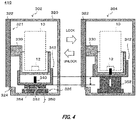
- Fig. 4 schematically illustrates one example of an internal configuration of the housing box 410.
- the housing box 410 is different from the housing box 210 in that the connection control part 350 is arranged in the connector holder 342.
- the housing box 410 may have a configuration similar with the housing box 210 except the above-described difference.
- the drive member 352 is elongated when the detection member 354 detects the closing operation of the lid 322.
- the position adjusting member 326 is arranged at an appropriate position and height of the housing 320.
- the drive member 352 comes into contact with the position adjusting member 326, the drive member 352 moves the connector holder 342 toward the battery holder 330. Accordingly, the connector 340 moves toward the connector 12 held by the battery holder 330.
- the detection member 354 detects the opening operation of the lid 322, (i) the drive member 352 is contracted or (ii) the drive member 352 separates the connector holder 342 from the battery holder 330. Accordingly, it is possible to separate the connector 12 and the connector 340.
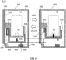
- Fig. 5 schematically illustrates one example of an internal configuration of a housing box 510.
- the housing box 510 is different from the housing box 210 and the housing box 410 in that the connection control part 550 is included instead of the connection control part 350.
- the housing box 510 may have a configuration similar with the housing box 210 or the housing box 410 except the above-described difference.
- connection control part 550 includes a drive member 552 and a detection member 554.
- the drive member 552 and the detection member 554 may have configurations similar with the drive member 352 and the detection member 354, respectively.
- at least a part is arranged between the battery holder 330 and the connector holder 342.
- the connection control part 550 controls the relative position of the battery holder 330 and the connector holder 342 by adjusting the length of the drive member 552 arranged between the battery holder 330 and the connector holder 342.
- a method of adjusting the length of the drive member 552 is not limited particularly.
- connection control part 550 is not limited to this embodiment.
- the connection control part 550 may be arranged on the surface on which the connector 340 of the connector holder 342 is held.
- a plurality of drive members 552 may be provided.
- the embodiments of Figs. 3 to 5 may be used in combination.
- FIG. 6 schematically illustrates one example of an internal configuration of the housing box 610 in a state where the lid 322 is opened.
- Fig. 7 schematically illustrates one example of the internal configuration of the housing box 610 in a state where the lid 322 is closed.
- the housing box 610 is different from the housing box 510 in that a connection control part 650 is included instead of the connection control part 550, and a position adjusting member 626 and a roller 628 are included instead of the position adjusting member 326.
- the connection control part 650 includes a mechanical mechanism which converts at least one of (i) the force generated by opening and closing the lid 322 and (ii) the gravity acting on the mobile battery 10 into the driving force of the connection control part 350.
- the force generated by opening and closing the lid 322 may be a rotating force generated by opening and closing the lid 322. Accordingly, for example, force F 2 for opening and closing the lid 322 is converted into force F 4 for driving the connector holder 342.
- a power transmission mechanism and a differential drive mechanism can be exemplified as the mechanical mechanism.
- a cam mechanism and a link mechanism can be exemplified as the power transmission mechanism. At least a part of the above-described mechanical mechanism may be used as the detection member.
- a part of the power transmission mechanism of the connection control part 650 is operated according to the opening and closing of the lid 322, and another part of the power transmission mechanism is operated in conjunction with the operation of the part, so that the relative position of the battery holder 330 and the connector holder 342 is changed.
- the length of the connection control part 650 arranged between the battery holder 330 and the connector holder 342 in a state where the lid 322 is opened is longer than the length of the connection control part 650 in a state where the lid 322 is closed.
- the length of the connection control part 650 increases as the opening degree of the lid 322 increases. For this reason, in Fig. 6 , the connector 340 and the connector 12 are not connected.
- the length of the connection control part 650 arranged between the battery holder 330 and the connector holder 342 is shortened. Further, when the lid 322 is closed, the connector holder 342 comes into contact with the roller 628.
- the position of the roller 628 is set by the position adjusting member 626 such that the connector 12 and the connector 340 are connected electrically in a state where the lid 322 is closed completely. For this reason, as the lid 322 is further closed after the connector holder 342 comes into contact with the roller 628, the connector 340 moves toward the connector 12. At this time, the mobile battery 10 is held by the battery holder 330. Thus, it is possible to prevent that at least one of the connector 12 and the connector 340 is damaged by the mass of the mobile battery 10. Similarly, as the lid 322 is opened from a state where the lid 322 is closed, the length of the connection control part 650 arranged between the battery holder 330 and the connector holder 342 may be extended.
- FIG. 8 illustrates a side section 802 of the housing box 810 in a state where the lid 322 is closed completely and a cross section A-A' 804.
- Fig. 9 illustrates the side section 802 of the housing box 810 in a state where the lid 322 is opened partially.
- Fig. 10 illustrates the side section 802 of the housing box 810 in a state where the lid 322 is opened completely.
- the housing box 810 is different from the housing box 610 in that the housing box includes a connection control part 850 as a specific example of the connection control part 650.
- the housing box 810 may have a configuration similar with the housing box 610 except the above-described difference.
- the connection control part 850 includes a cam 852 and a rotation member 854 rotated by the opening and closing operation of the lid 322.
- the cam 852 and the rotation member 854 are attached to the same rotational axis 856.
- reference sign 853 indicates a reference circle of the cam 852.
- a gear 954 is arranged in an outer peripheral portion of the rotation member 854.
- a rail member 920 is attached to the lid 322.
- a gear 922 engaged with the gear 954 of the rotation member 854 is arranged in the rail member 920. Accordingly, the cam 852 rotates about the rotational axis 856 by the opening and closing operation of the lid 322.
- the connector holder 342 functions as a follower of the cam 852. Accordingly, the connector holder 342 moves translationally to the battery holder 330 in conjunction with the opening and closing operation of the lid 322.
- the relative position of the connector 12 and the connector 340 is adjusted by the translational movement of the connector holder 342.
- an outer surface 930 of the battery holder 330 and an inner surface 940 of the connector holder 342 face each other.
- the distance of the outer surface 930 and the inner surface 940 in a state where the lid 322 is closed is smaller than the distance of the outer surface 930 and the inner surface 940 in a state where the lid 322 is opened.
- a distance between the rotational axis 856 and the inner surface 940 of the connector holder 342 is substantially the same as a reference circle radius R 4 of the cam 852.
- an opening surface S 2 of the connector holder 342 is positioned above a surface S 4 perpendicular to the insertion direction (a vertical direction in Fig. 8 ) of the mobile battery 10 through the rotational axis 856. That is, the distance between the opening surface S 2 and the outer surface 930 of the battery holder 330 is longer than the distance between the surface S 4 and the inner surface 940 of the battery holder 330.
- the distance between the rotational axis 856 and the inner surface 940 of the connector holder 342 is substantially the same as the length R 2 of the long diameter of the cam 852. For this reason, according to this embodiment, as the lid 322 is opened, force of the cam 852 pushing the connector holder 342 becomes large.
- the cam 852 pushes the connector holder 342, and thus the connector holder 342 is gradually separated from the battery holder 330.
- This point is understood from the fact that the distance between the opening surface S 2 and the outer surface 930 of the battery holder 330 is shorter than the distance between the surface S 4 and the inner surface 940 of the battery holder 330 in Fig. 10 .
- the connector holder 342 and the battery holder 330 are separated to some extent, the connector 340 is detached from the connector 12.
- connection control part 650 may be similarly with that of the connection control part 550.
- the connector holder 342 and the battery holder 330 are separated sufficiently, and the connector 340 and the connector 12 are also separated.
- the rail member 920 fixed to the lid 322 moves to rotate the rotation member 854.
- the cam 852 and the rotation member 854 are attached to the same rotational axis 856, and a relation of the long diameter of the cam 852 and the reference circle is as above.
- FIG. 11 illustrates a side section 1102 of the housing box 1110 in a state where the lid 322 is closed completely and a cross section A-A' 1104.
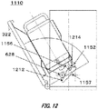
- Fig. 12 illustrates the side section 1102 of the housing box 1110 in a state where the lid 322 is partially opened.
- Fig. 13 illustrates the side section 1102 of the housing box 1110 in a state where the lid 322 is opened completely.
- the housing box 1110 is different from the housing box 610 and the housing box 810 in that a connection control part 1150 is included as a specific example of the connection control part 650.
- the housing box 1110 is different from the housing box 610 and the housing box 810 in that the connection control part 1150 is included in a bottom portion of the connector holder 342.
- the housing box 1110 may have a configuration similar with the housing box 610 or the housing box 810 except the above-described difference.
- connection control part 1150 includes a rod 1152 and a link 1154.
- the link 1154 includes a link member 1156 and a link member 1157.
- the link member 1157 can rotate about the rotational axis 1158.
- the connector holder 342 is configured to move translationally in the insertion direction of the mobile battery 10.
- the rod 1152 may be one example of an extension member.
- the link 1154 may be one example of a link member.
- the link member 1157 may be one example of a first link member.
- the link member 1156 may be one example of a second link member.
- the rod 1152 is arranged on a surface facing the connector holder 342 among the surfaces of the battery holder 330.
- the rod 1152 is arranged on the bottom surface of the battery holder 330.
- An opening for passing through the rod 1152 is formed at the position corresponding to the rod 1152 of the connector holder 342. Accordingly, the rod 1152 can extend in the insertion direction (a vertical direction in Fig. 11 ) of the mobile battery 10 through the connector holder 342.
- the link 1154 is arranged on the surface (referred to as the bottom surface of the connector holder 342 in some cases) opposite to the surface (referred to as the inner surface of the connector holder 342 in some cases) facing the battery holder 330 among the surfaces of the connector holder 342.
- one end of the link member 1156 is fixed to the bottom surface of the connector holder 342.
- the other end of the link member 1156 is rotatably coupled with the link member 1157.
- the link member 1157 includes a surface 1212 contacting the roller 628 and a surface 1214 contacting the rod 1152.
- the link member 1157 is coupled with the rotational axis 1158 so as to rotate about an axis located near the intersection of the surface 1212 and the surface 1214.
- the connector holder 342 and the battery holder 330 are separated sufficiently, and the connector 340 and the connector 12 are also separated.
- the position of the roller 628 is set such that the connector 12 and the connector 340 are connected electrically in a state where the lid 322 is closed completely.
- the outer surface of the connector holder 342 comes into contact with the roller 628.
- the connector holder 342 moves toward the battery holder 330.
- the connector 340 moves toward the connector 12, and the connector 340 and the connector 12 are connected finally.
- the length of the rod 1152 protruding from the outer surface of the connector holder 342 is extended.
- the rod 1152 pushes the surface 1214 of the link member 1157.
- the link member 1157 rotates about the rotational axis 1158 by the amount pushed by the rod 1152. Accordingly, such an operation can be included in the next operation of opening the lid 322.
Applications Claiming Priority (2)
| Application Number | Priority Date | Filing Date | Title |
|---|---|---|---|
| JP2017059355A JP6286084B1 (ja) | 2017-03-24 | 2017-03-24 | 収容装置 |
| PCT/JP2018/011553 WO2018174215A1 (ja) | 2017-03-24 | 2018-03-22 | 収容装置 |
Publications (3)
| Publication Number | Publication Date |
|---|---|
| EP3605644A1 true EP3605644A1 (de) | 2020-02-05 |
| EP3605644A4 EP3605644A4 (de) | 2020-02-12 |
| EP3605644B1 EP3605644B1 (de) | 2020-08-19 |
Family
ID=61282737
Family Applications (1)
| Application Number | Title | Priority Date | Filing Date |
|---|---|---|---|
| EP18771304.5A Active EP3605644B1 (de) | 2017-03-24 | 2018-03-22 | Unterbringungsvorrichtung |
Country Status (11)
| Country | Link |
|---|---|
| US (1) | US11056806B2 (de) |
| EP (1) | EP3605644B1 (de) |
| JP (1) | JP6286084B1 (de) |
| KR (1) | KR20190132663A (de) |
| CN (1) | CN110476270A (de) |
| AU (1) | AU2018240904B2 (de) |
| CA (1) | CA3057422A1 (de) |
| ES (1) | ES2820293T3 (de) |
| PH (1) | PH12019550184A1 (de) |
| TW (1) | TWI785020B (de) |
| WO (1) | WO2018174215A1 (de) |
Families Citing this family (17)
| Publication number | Priority date | Publication date | Assignee | Title |
|---|---|---|---|---|
| WO2019065154A1 (ja) * | 2017-09-29 | 2019-04-04 | 本田技研工業株式会社 | マガジン式充電装置 |
| WO2019176241A1 (ja) * | 2018-03-12 | 2019-09-19 | 本田技研工業株式会社 | 可搬型バッテリの充電器 |
| CN111788711B (zh) * | 2018-03-12 | 2023-06-16 | 本田技研工业株式会社 | 移动型蓄电池的充电器 |
| JP6924165B2 (ja) * | 2018-04-18 | 2021-08-25 | 本田技研工業株式会社 | 可搬型バッテリの充電器 |
| JP7001031B2 (ja) * | 2018-09-19 | 2022-01-19 | 株式会社デンソーウェーブ | 充電台 |
| WO2020179262A1 (ja) * | 2019-03-06 | 2020-09-10 | パナソニックIpマネジメント株式会社 | バッテリ管理システム、バッテリ管理方法および端末装置 |
| JP7149410B2 (ja) * | 2019-03-19 | 2022-10-06 | 本田技研工業株式会社 | バッテリ収納装置、および電動車両 |
| US20220224047A1 (en) | 2019-05-21 | 2022-07-14 | Honda Motor Co., Ltd. | Power transmission device and electric power device |
| KR102424745B1 (ko) * | 2019-12-12 | 2022-07-25 | 한국광기술원 | 배터리 랙 장치 |
| CN115280586B (zh) | 2020-02-25 | 2023-08-18 | 米沃奇电动工具公司 | 电池包 |
| JPWO2021171825A1 (de) * | 2020-02-26 | 2021-09-02 | ||
| JP7095161B2 (ja) * | 2020-06-30 | 2022-07-04 | 典型工場有限公司 | 車両用電池のための充電装置及び充電システム |
| CN112165823B (zh) * | 2020-09-22 | 2022-07-05 | 科华数据股份有限公司 | 一种应用于连接器的安全保护装置及安全控制方法 |
| EP4228054A1 (de) | 2020-10-07 | 2023-08-16 | Honda Motor Co., Ltd. | Haltevorrichtung |
| JP7430676B2 (ja) | 2021-09-07 | 2024-02-13 | プライムアースEvエナジー株式会社 | 電池ユニットの収納構造 |
| JPWO2023058752A1 (de) * | 2021-10-07 | 2023-04-13 | ||
| WO2023190276A1 (ja) * | 2022-03-28 | 2023-10-05 | 本田技研工業株式会社 | 収容装置 |
Family Cites Families (85)
| Publication number | Priority date | Publication date | Assignee | Title |
|---|---|---|---|---|
| US4450400A (en) * | 1981-12-04 | 1984-05-22 | Gwyn Marion V | Battery replacement system for electric vehicles |
| US4413219A (en) * | 1982-04-02 | 1983-11-01 | Interlake, Inc. | Fork truck battery charging system |
| JPS609055A (ja) * | 1983-06-28 | 1985-01-18 | Mitsubishi Electric Corp | 電気機器の蓄電池収納装置 |
| JPS60165047A (ja) * | 1984-02-08 | 1985-08-28 | Daifuku Co Ltd | バッテリー充電設備 |
| JPH0295161U (de) * | 1989-01-14 | 1990-07-30 | ||
| EP0412051B1 (de) * | 1989-07-31 | 1993-09-22 | Maschinenfabrik Rieter Ag | Einrichtung zum Auswechseln und Laden von Energiespeichern von Transportfahrzeugen |
| JP2585378Y2 (ja) * | 1992-07-14 | 1998-11-18 | 株式会社東芝 | 充電器 |
| DE4242659A1 (de) * | 1992-12-17 | 1994-06-23 | Truetzschler Gmbh & Co Kg | Vorrichtung zum Transport mindestens einer Kanne zwischen einer faserbandabliefernden Spinnereimaschine, z. B. Karde und einer fasergespeisten Spinnereimaschine, z. B. Strecke |
| US5612606A (en) * | 1994-09-15 | 1997-03-18 | David C. Guimarin | Battery exchange system for electric vehicles |
| US5668460A (en) * | 1994-10-31 | 1997-09-16 | Lashstar, Inc. | Battery recharger turntable |
| IT1282535B1 (it) * | 1995-11-21 | 1998-03-26 | Alberto Ciarla | Attrezzatura per il noleggio di veicoli a propulsione elettrica, in particolare scooter e per la sostituzione e ricarica delle batterie |
| US5998963A (en) * | 1998-06-11 | 1999-12-07 | Aarseth; Einar | Electric vehicle service center and method for exchanging and charging vehicle batteries |
| IT1320305B1 (it) * | 1999-05-25 | 2003-11-26 | Honda Motor Co Ltd | Apparecchiatura per il cambio di batterie. |
| US7520355B2 (en) * | 2000-07-06 | 2009-04-21 | Chaney George T | Hybrid electric vehicle chassis with removable battery module |
| US6936372B1 (en) * | 2002-08-15 | 2005-08-30 | Tyco Electronics Power Systems, Inc. | Environmental control system for use with a battery cabinet and method of operating a fan therein |
| JP3881317B2 (ja) * | 2003-01-30 | 2007-02-14 | 川崎重工業株式会社 | 鉄道車両用バッテリー箱 |
| JP2005174681A (ja) * | 2003-12-10 | 2005-06-30 | Japan Storage Battery Co Ltd | 着脱機構 |
| US7004710B1 (en) * | 2004-02-26 | 2006-02-28 | Quade Jim D | Hydraulic battery changer |
| US7602143B2 (en) * | 2005-11-04 | 2009-10-13 | Peter David Capizzo | System for replenishing energy sources onboard different types of automotive vehicles |
| DE102006031461A1 (de) * | 2006-07-07 | 2008-01-10 | Jungheinrich Aktiengesellschaft | Batteriewechselsystem für ein batteriebetriebenes Flurförderzeug |
| JP5405858B2 (ja) * | 2008-04-14 | 2014-02-05 | 日産自動車株式会社 | 組電池、組電池の製造方法および組電池を搭載した車両 |
| US8006793B2 (en) * | 2008-09-19 | 2011-08-30 | Better Place GmbH | Electric vehicle battery system |
| US20100292877A1 (en) * | 2009-05-18 | 2010-11-18 | Gabrielle W. Lee | Comprehensive engineering / operation system for electric vehicle and smart networked and decentralized power storage |
| JP5374409B2 (ja) * | 2010-02-18 | 2013-12-25 | 川崎重工業株式会社 | 鉄道車両のバッテリー格納装置 |
| JP5353779B2 (ja) * | 2010-03-16 | 2013-11-27 | 株式会社豊田自動織機 | バッテリ充電用倉庫 |
| SE536036C2 (sv) * | 2010-06-21 | 2013-04-09 | Sten Corfitsen | Förfarande för att byta batteri i batteridrivna fordon. |
| CN102377199A (zh) * | 2010-08-18 | 2012-03-14 | 朱孟龙 | 电动汽车智能连接充电装置 |
| CN102097840B (zh) * | 2010-12-31 | 2013-12-11 | 云南昆船数码科技有限公司 | 电动车充电适配托盘设备 |
| KR101355961B1 (ko) * | 2011-04-25 | 2014-02-03 | 주식회사 엘지화학 | 배터리팩 수납장치 및 이를 이용한 전력 저장용 배터리팩의 냉각 장치 |
| KR101264338B1 (ko) * | 2011-07-14 | 2013-05-14 | 삼성에스디아이 주식회사 | 랙 하우징 조립체 및 이를 구비한 전력저장장치 |
| ES2748199T3 (es) | 2011-07-26 | 2020-03-13 | Gogoro Inc | Aparato, método y artículo para proporcionar información sobre la disponibilidad de dispositivos de almacenamiento de energía en una máquina de recogida, carga y distribución de dispositivos de almacenamiento de energía |
| JP6010619B2 (ja) | 2011-07-26 | 2016-10-19 | ゴゴロ インク | ユーザープロファイルに基づいた電池などの電力貯蔵装置の認証、セキュリティ、及び制御のための装置、方法、及び物品 |
| US8560147B2 (en) | 2011-07-26 | 2013-10-15 | Gogoro, Inc. | Apparatus, method and article for physical security of power storage devices in vehicles |
| US9437058B2 (en) | 2011-07-26 | 2016-09-06 | Gogoro Inc. | Dynamically limiting vehicle operation for best effort economy |
| ES2701745T3 (es) | 2011-07-26 | 2019-02-25 | Gogoro Inc | Aparato, método y artículo para la redistribución de dispositivos de almacenamiento de energía, como por ejemplo baterías, entre máquinas de recogida, carga y distribución |
| WO2013016561A1 (en) | 2011-07-26 | 2013-01-31 | Gogoro, Inc. | Apparatus, method and article for providing locations of power storage device collection, charging and distribution machines |
| ES2967056T3 (es) | 2011-07-26 | 2024-04-25 | Gogoro Inc | Aparato, método y artículo para autenticación, seguridad y control de dispositivos de almacenamiento de energía, como por ejemplo baterías |
| EP2737572B1 (de) | 2011-07-26 | 2022-08-24 | Gogoro Inc. | Wärmeverwaltung von komponenten in fahrzeugen mit elektromotorantrieb |
| US10186094B2 (en) | 2011-07-26 | 2019-01-22 | Gogoro Inc. | Apparatus, method and article for providing locations of power storage device collection, charging and distribution machines |
| JP5793245B2 (ja) | 2011-07-26 | 2015-10-14 | ゴゴロ インク | 乗り物診断データを提供するための装置、方法、および物品 |
| EP2737601B1 (de) | 2011-07-26 | 2020-04-08 | Gogoro Inc. | Vorrichtung, verfahren und artikel zum sammeln, laden und verteilen von energiespeichervorrichtungen, z. b. batterien |
| WO2013016564A2 (en) | 2011-07-26 | 2013-01-31 | Gogoro, Inc. | Apparatus, method and article for reserving power storage devices at reserving power storage device collection, charging and distribution machines |
| DE102011082092B4 (de) * | 2011-09-02 | 2023-11-09 | Bayerische Motoren Werke Aktiengesellschaft | Vorrichtung zur automatisierten Herstellung und Trennung einer Ladeverbindung bei einem Plug-in-Fahrzeug sowie Verfahren zur Herstellung einer Ladeverbindung |
| WO2013070793A1 (en) | 2011-11-08 | 2013-05-16 | Gogoro, Inc. | Apparatus, method and article for security of vehicles |
| WO2013143460A1 (zh) * | 2012-03-27 | 2013-10-03 | 台湾立凯绿能移动股份有限公司 | 电动车辆抽取式电池固定装置组及其锁固方法 |
| SE537055C2 (sv) * | 2012-04-18 | 2014-12-23 | Sten Corfitsen | Anordning och förfarande för byte av batterier i batteridrivna fordon |
| TWI523317B (zh) * | 2012-04-26 | 2016-02-21 | 宏碁股份有限公司 | 行動裝置 |
| US8694155B2 (en) * | 2012-06-26 | 2014-04-08 | Motex Products Co., Ltd. | System for auto-exchanging of electric vehicle battery |
| JP6810504B2 (ja) | 2012-11-16 | 2021-01-06 | ゴゴロ インク | 車両方向指示器のための装置、方法及び物品 |
| US9854438B2 (en) | 2013-03-06 | 2017-12-26 | Gogoro Inc. | Apparatus, method and article for authentication, security and control of portable charging devices and power storage devices, such as batteries |
| US8985610B2 (en) | 2013-03-08 | 2015-03-24 | Gogoro Inc. | Suspension structure and driving assembly comprising the same |
| WO2014164812A1 (en) | 2013-03-12 | 2014-10-09 | Gogoro, Inc. | Apparatus, method and article for changing portable electrical power storage device exchange plans |
| US11222485B2 (en) | 2013-03-12 | 2022-01-11 | Gogoro Inc. | Apparatus, method and article for providing information regarding a vehicle via a mobile device |
| CN105210108A (zh) | 2013-03-13 | 2015-12-30 | 睿能创意公司 | 用于经由移动设备提供关于车辆的信息的装置、方法和物品 |
| CN105210257B (zh) * | 2013-03-15 | 2018-11-13 | 睿能创意公司 | 用于对电存储设备进行收集和分配的模块化系统 |
| JP6102541B2 (ja) * | 2013-06-13 | 2017-03-29 | 住友電気工業株式会社 | 収納装置および蓄電池交換方法 |
| SE1350769A1 (sv) * | 2013-06-25 | 2014-08-26 | Sten Corfitsen | Förfarande och anordning för byte av ett batteri i ett fordon |
| CN108189701B (zh) | 2013-08-06 | 2021-10-22 | 睿能创意公司 | 基于电能储存装置热简况调节电动车系统 |
| CN105829160B (zh) | 2013-08-06 | 2017-10-24 | 睿能创意公司 | 使用单个或多个电池单元为电动车供电的系统和方法 |
| US10158102B2 (en) | 2013-08-30 | 2018-12-18 | Gogoro Inc. | Portable electrical energy storage device with thermal runaway mitigation |
| JP2015049447A (ja) * | 2013-09-03 | 2015-03-16 | カシオ電子工業株式会社 | 画像形成装置 |
| JP6261975B2 (ja) * | 2013-12-11 | 2018-01-17 | 株式会社東芝 | 発熱体収容装置 |
| US9238414B2 (en) * | 2014-01-02 | 2016-01-19 | The Boeing Company | Charging system for battery-powered unmanned aerial vehicles |
| NO340313B1 (no) * | 2014-01-08 | 2017-03-27 | Jakob Hatteland Logistics As | Fjernstyrt kjøretøy for å plukke opp lagringsbeholdere fra et lagringssystem, lagringssystem for lagring av beholdere og fremgangsmåte for å bytte en strømkilde |
| US9566954B2 (en) * | 2014-03-10 | 2017-02-14 | Max Moskowitz | Vehicular accessory |
| WO2016036742A1 (en) * | 2014-09-04 | 2016-03-10 | Gogoro Inc. | Apparatus, system, and method for vending, charging, and two-way distribution of electrical energy storage devices |
| KR102306445B1 (ko) * | 2014-10-07 | 2021-09-28 | 삼성에스디아이 주식회사 | 에너지 저장 장치 |
| US9827865B2 (en) * | 2014-12-30 | 2017-11-28 | General Electric Company | Systems and methods for recharging vehicle-mounted energy storage devices |
| JP6516101B2 (ja) * | 2015-03-09 | 2019-05-22 | パナソニックIpマネジメント株式会社 | 蓄電池収納装置 |
| US9187004B1 (en) * | 2015-04-03 | 2015-11-17 | Harold William Davis | Electric vehicle carousel battery exchange/charging system |
| GB201514204D0 (en) * | 2015-08-11 | 2015-09-23 | Vivarail Ltd | Electric rail carriage |
| CN107004923B (zh) * | 2015-09-01 | 2021-02-02 | 松下知识产权经营株式会社 | 蓄电池用架以及蓄电装置 |
| JP6573073B2 (ja) * | 2015-10-05 | 2019-09-11 | パナソニックIpマネジメント株式会社 | バッテリ装置の充電構造および電動車両 |
| US9964415B2 (en) * | 2015-11-13 | 2018-05-08 | Nio Usa, Inc. | Tracking power consumption and payment |
| JP6724343B2 (ja) * | 2015-11-17 | 2020-07-15 | オムロン株式会社 | 予約管理装置、予約管理システムおよび予約管理方法 |
| JP6686395B2 (ja) * | 2015-12-01 | 2020-04-22 | オムロン株式会社 | バッテリ充電装置、バッテリ充電システムおよびバッテリ充電方法 |
| US9987938B2 (en) * | 2015-12-04 | 2018-06-05 | General Electric Company | Energy storage device, exchange apparatus, and method for exchanging an energy storage device |
| WO2017154478A1 (ja) * | 2016-03-10 | 2017-09-14 | パナソニックIpマネジメント株式会社 | 蓄電装置 |
| US9873408B2 (en) * | 2016-05-11 | 2018-01-23 | Peter D. Capizzo | Device for refueling, exchanging, and charging power sources on remote controlled vehicles, UAVs, drones, or any type of robotic vehicle or machine with mobility |
| US10112471B2 (en) * | 2016-05-18 | 2018-10-30 | Sharp Kabushiki Kaisha | Battery-driven traveling device |
| NO344308B1 (en) * | 2016-06-21 | 2019-10-28 | Autostore Tech As | Storage system comprising a charging station assembly and method of replacing the power source of a remotely operated vehicle |
| CN106099537A (zh) * | 2016-07-26 | 2016-11-09 | 蔚来汽车有限公司 | 用于动力电池的自动插拔充电装置 |
| JP6286083B1 (ja) * | 2017-03-23 | 2018-02-28 | 本田技研工業株式会社 | 収容装置 |
| DE102017115702A1 (de) * | 2017-07-12 | 2019-01-17 | Dr. Ing. H.C. F. Porsche Aktiengesellschaft | Gehäuse für eine Stromtankstelle und Verfahren zu dessen Herstellung |
| JP6629381B2 (ja) * | 2017-09-29 | 2020-01-15 | 本田技研工業株式会社 | マガジン式充電装置 |
-
2017
- 2017-03-24 JP JP2017059355A patent/JP6286084B1/ja active Active
-
2018
- 2018-03-12 TW TW107108331A patent/TWI785020B/zh active
- 2018-03-22 ES ES18771304T patent/ES2820293T3/es active Active
- 2018-03-22 EP EP18771304.5A patent/EP3605644B1/de active Active
- 2018-03-22 CN CN201880020874.XA patent/CN110476270A/zh active Pending
- 2018-03-22 AU AU2018240904A patent/AU2018240904B2/en active Active
- 2018-03-22 WO PCT/JP2018/011553 patent/WO2018174215A1/ja unknown
- 2018-03-22 KR KR1020197031120A patent/KR20190132663A/ko not_active Application Discontinuation
- 2018-03-22 CA CA3057422A patent/CA3057422A1/en active Pending
-
2019
- 2019-09-06 US US16/562,458 patent/US11056806B2/en active Active
- 2019-09-20 PH PH12019550184A patent/PH12019550184A1/en unknown
Also Published As
| Publication number | Publication date |
|---|---|
| CN110476270A (zh) | 2019-11-19 |
| EP3605644A4 (de) | 2020-02-12 |
| JP6286084B1 (ja) | 2018-02-28 |
| EP3605644B1 (de) | 2020-08-19 |
| ES2820293T3 (es) | 2021-04-20 |
| WO2018174215A1 (ja) | 2018-09-27 |
| KR20190132663A (ko) | 2019-11-28 |
| TWI785020B (zh) | 2022-12-01 |
| AU2018240904A1 (en) | 2019-09-26 |
| TW201840092A (zh) | 2018-11-01 |
| JP2018163757A (ja) | 2018-10-18 |
| US20190393627A1 (en) | 2019-12-26 |
| PH12019550184A1 (en) | 2020-06-08 |
| CA3057422A1 (en) | 2018-09-27 |
| US11056806B2 (en) | 2021-07-06 |
| AU2018240904B2 (en) | 2023-05-18 |
Similar Documents
| Publication | Publication Date | Title |
|---|---|---|
| EP3605644B1 (de) | Unterbringungsvorrichtung | |
| EP3605645A1 (de) | Behältervorrichtung | |
| US20170283090A1 (en) | Unmanned aerial vehicle battery swapping system | |
| JP5848816B2 (ja) | 電子機器のための自動ヒンジロックアセンブリ | |
| US20170222456A1 (en) | Charging stylus inside hinge of portable computing device | |
| US9276423B2 (en) | Charging base for multiple different sized components positioned using rotating elements | |
| CN103582372A (zh) | 可携式电子装置及其电子模组固定结构 | |
| US20050059344A1 (en) | Accommodation device for bluetooth earphone | |
| US8721346B2 (en) | Signal transmission module | |
| JP2024016229A (ja) | ディスプレイ装置 | |
| CN102708913A (zh) | 一种闪存盘及移动硬盘 | |
| KR101625305B1 (ko) | 모바일 단말 및 모바일 단말의 후면 커버 | |
| KR20130024666A (ko) | 데이터 전송 장치 및 이를 이용한 데이터 전송 방법 | |
| CN108389321A (zh) | 一种售卖机 | |
| EP4235368A1 (de) | Schutzhülle für elektronische vorrichtung und anordnung aus elektronischer vorrichtung | |
| CN111629088B (zh) | 电子设备 | |
| CN203554558U (zh) | Wifi相机 | |
| CN205281333U (zh) | 一种基于陀螺仪的螺旋桨式笔记本电脑摔落保护装置 | |
| CN204195730U (zh) | 一种快拆式工具盒 | |
| CN110764386A (zh) | 作用杆组件和处理盒 | |
| KR20050099480A (ko) | 휴대폰과 노트북 컴퓨터를 일체화하는 케이지를 내장한노트북 컴퓨터 | |
| CN102548294A (zh) | 信号传输模块 |
Legal Events
| Date | Code | Title | Description |
|---|---|---|---|
| STAA | Information on the status of an ep patent application or granted ep patent |
Free format text: STATUS: THE INTERNATIONAL PUBLICATION HAS BEEN MADE |
|
| PUAI | Public reference made under article 153(3) epc to a published international application that has entered the european phase |
Free format text: ORIGINAL CODE: 0009012 |
|
| STAA | Information on the status of an ep patent application or granted ep patent |
Free format text: STATUS: REQUEST FOR EXAMINATION WAS MADE |
|
| 17P | Request for examination filed |
Effective date: 20191023 |
|
| AK | Designated contracting states |
Kind code of ref document: A1 Designated state(s): AL AT BE BG CH CY CZ DE DK EE ES FI FR GB GR HR HU IE IS IT LI LT LU LV MC MK MT NL NO PL PT RO RS SE SI SK SM TR |
|
| AX | Request for extension of the european patent |
Extension state: BA ME |
|
| A4 | Supplementary search report drawn up and despatched |
Effective date: 20200114 |
|
| RIC1 | Information provided on ipc code assigned before grant |
Ipc: H02J 7/00 20060101ALI20200108BHEP Ipc: H01M 2/10 20060101AFI20200108BHEP Ipc: H01R 9/28 20060101ALI20200108BHEP Ipc: H01M 10/46 20060101ALI20200108BHEP |
|
| RIC1 | Information provided on ipc code assigned before grant |
Ipc: H01M 10/46 20060101ALI20200324BHEP Ipc: H01M 2/10 20060101AFI20200324BHEP Ipc: H01R 9/28 20060101ALI20200324BHEP Ipc: H02J 7/00 20060101ALI20200324BHEP |
|
| GRAP | Despatch of communication of intention to grant a patent |
Free format text: ORIGINAL CODE: EPIDOSNIGR1 |
|
| STAA | Information on the status of an ep patent application or granted ep patent |
Free format text: STATUS: GRANT OF PATENT IS INTENDED |
|
| INTG | Intention to grant announced |
Effective date: 20200507 |
|
| DAV | Request for validation of the european patent (deleted) | ||
| DAX | Request for extension of the european patent (deleted) | ||
| GRAS | Grant fee paid |
Free format text: ORIGINAL CODE: EPIDOSNIGR3 |
|
| GRAA | (expected) grant |
Free format text: ORIGINAL CODE: 0009210 |
|
| STAA | Information on the status of an ep patent application or granted ep patent |
Free format text: STATUS: THE PATENT HAS BEEN GRANTED |
|
| AK | Designated contracting states |
Kind code of ref document: B1 Designated state(s): AL AT BE BG CH CY CZ DE DK EE ES FI FR GB GR HR HU IE IS IT LI LT LU LV MC MK MT NL NO PL PT RO RS SE SI SK SM TR |
|
| REG | Reference to a national code |
Ref country code: CH Ref legal event code: EP |
|
| REG | Reference to a national code |
Ref country code: DE Ref legal event code: R096 Ref document number: 602018007136 Country of ref document: DE |
|
| REG | Reference to a national code |
Ref country code: AT Ref legal event code: REF Ref document number: 1304962 Country of ref document: AT Kind code of ref document: T Effective date: 20200915 |
|
| REG | Reference to a national code |
Ref country code: IE Ref legal event code: FG4D |
|
| REG | Reference to a national code |
Ref country code: NL Ref legal event code: FP |
|
| REG | Reference to a national code |
Ref country code: SE Ref legal event code: TRGR |
|
| REG | Reference to a national code |
Ref country code: DE Ref legal event code: R079 Ref document number: 602018007136 Country of ref document: DE Free format text: PREVIOUS MAIN CLASS: H01M0002100000 Ipc: H01M0050200000 |
|
| REG | Reference to a national code |
Ref country code: LT Ref legal event code: MG4D |
|
| PG25 | Lapsed in a contracting state [announced via postgrant information from national office to epo] |
Ref country code: NO Free format text: LAPSE BECAUSE OF FAILURE TO SUBMIT A TRANSLATION OF THE DESCRIPTION OR TO PAY THE FEE WITHIN THE PRESCRIBED TIME-LIMIT Effective date: 20201119 Ref country code: BG Free format text: LAPSE BECAUSE OF FAILURE TO SUBMIT A TRANSLATION OF THE DESCRIPTION OR TO PAY THE FEE WITHIN THE PRESCRIBED TIME-LIMIT Effective date: 20201119 Ref country code: HR Free format text: LAPSE BECAUSE OF FAILURE TO SUBMIT A TRANSLATION OF THE DESCRIPTION OR TO PAY THE FEE WITHIN THE PRESCRIBED TIME-LIMIT Effective date: 20200819 Ref country code: PT Free format text: LAPSE BECAUSE OF FAILURE TO SUBMIT A TRANSLATION OF THE DESCRIPTION OR TO PAY THE FEE WITHIN THE PRESCRIBED TIME-LIMIT Effective date: 20201221 Ref country code: FI Free format text: LAPSE BECAUSE OF FAILURE TO SUBMIT A TRANSLATION OF THE DESCRIPTION OR TO PAY THE FEE WITHIN THE PRESCRIBED TIME-LIMIT Effective date: 20200819 Ref country code: LT Free format text: LAPSE BECAUSE OF FAILURE TO SUBMIT A TRANSLATION OF THE DESCRIPTION OR TO PAY THE FEE WITHIN THE PRESCRIBED TIME-LIMIT Effective date: 20200819 Ref country code: GR Free format text: LAPSE BECAUSE OF FAILURE TO SUBMIT A TRANSLATION OF THE DESCRIPTION OR TO PAY THE FEE WITHIN THE PRESCRIBED TIME-LIMIT Effective date: 20201120 |
|
| REG | Reference to a national code |
Ref country code: AT Ref legal event code: MK05 Ref document number: 1304962 Country of ref document: AT Kind code of ref document: T Effective date: 20200819 |
|
| PG25 | Lapsed in a contracting state [announced via postgrant information from national office to epo] |
Ref country code: LV Free format text: LAPSE BECAUSE OF FAILURE TO SUBMIT A TRANSLATION OF THE DESCRIPTION OR TO PAY THE FEE WITHIN THE PRESCRIBED TIME-LIMIT Effective date: 20200819 Ref country code: PL Free format text: LAPSE BECAUSE OF FAILURE TO SUBMIT A TRANSLATION OF THE DESCRIPTION OR TO PAY THE FEE WITHIN THE PRESCRIBED TIME-LIMIT Effective date: 20200819 Ref country code: RS Free format text: LAPSE BECAUSE OF FAILURE TO SUBMIT A TRANSLATION OF THE DESCRIPTION OR TO PAY THE FEE WITHIN THE PRESCRIBED TIME-LIMIT Effective date: 20200819 Ref country code: IS Free format text: LAPSE BECAUSE OF FAILURE TO SUBMIT A TRANSLATION OF THE DESCRIPTION OR TO PAY THE FEE WITHIN THE PRESCRIBED TIME-LIMIT Effective date: 20201219 |
|
| REG | Reference to a national code |
Ref country code: ES Ref legal event code: FG2A Ref document number: 2820293 Country of ref document: ES Kind code of ref document: T3 Effective date: 20210420 |
|
| PG25 | Lapsed in a contracting state [announced via postgrant information from national office to epo] |
Ref country code: SM Free format text: LAPSE BECAUSE OF FAILURE TO SUBMIT A TRANSLATION OF THE DESCRIPTION OR TO PAY THE FEE WITHIN THE PRESCRIBED TIME-LIMIT Effective date: 20200819 Ref country code: RO Free format text: LAPSE BECAUSE OF FAILURE TO SUBMIT A TRANSLATION OF THE DESCRIPTION OR TO PAY THE FEE WITHIN THE PRESCRIBED TIME-LIMIT Effective date: 20200819 Ref country code: DK Free format text: LAPSE BECAUSE OF FAILURE TO SUBMIT A TRANSLATION OF THE DESCRIPTION OR TO PAY THE FEE WITHIN THE PRESCRIBED TIME-LIMIT Effective date: 20200819 Ref country code: CZ Free format text: LAPSE BECAUSE OF FAILURE TO SUBMIT A TRANSLATION OF THE DESCRIPTION OR TO PAY THE FEE WITHIN THE PRESCRIBED TIME-LIMIT Effective date: 20200819 Ref country code: EE Free format text: LAPSE BECAUSE OF FAILURE TO SUBMIT A TRANSLATION OF THE DESCRIPTION OR TO PAY THE FEE WITHIN THE PRESCRIBED TIME-LIMIT Effective date: 20200819 |
|
| REG | Reference to a national code |
Ref country code: DE Ref legal event code: R097 Ref document number: 602018007136 Country of ref document: DE |
|
| PG25 | Lapsed in a contracting state [announced via postgrant information from national office to epo] |
Ref country code: AT Free format text: LAPSE BECAUSE OF FAILURE TO SUBMIT A TRANSLATION OF THE DESCRIPTION OR TO PAY THE FEE WITHIN THE PRESCRIBED TIME-LIMIT Effective date: 20200819 Ref country code: AL Free format text: LAPSE BECAUSE OF FAILURE TO SUBMIT A TRANSLATION OF THE DESCRIPTION OR TO PAY THE FEE WITHIN THE PRESCRIBED TIME-LIMIT Effective date: 20200819 |
|
| PLBE | No opposition filed within time limit |
Free format text: ORIGINAL CODE: 0009261 |
|
| STAA | Information on the status of an ep patent application or granted ep patent |
Free format text: STATUS: NO OPPOSITION FILED WITHIN TIME LIMIT |
|
| PG25 | Lapsed in a contracting state [announced via postgrant information from national office to epo] |
Ref country code: SK Free format text: LAPSE BECAUSE OF FAILURE TO SUBMIT A TRANSLATION OF THE DESCRIPTION OR TO PAY THE FEE WITHIN THE PRESCRIBED TIME-LIMIT Effective date: 20200819 |
|
| 26N | No opposition filed |
Effective date: 20210520 |
|
| PG25 | Lapsed in a contracting state [announced via postgrant information from national office to epo] |
Ref country code: MC Free format text: LAPSE BECAUSE OF FAILURE TO SUBMIT A TRANSLATION OF THE DESCRIPTION OR TO PAY THE FEE WITHIN THE PRESCRIBED TIME-LIMIT Effective date: 20200819 |
|
| REG | Reference to a national code |
Ref country code: CH Ref legal event code: PL |
|
| REG | Reference to a national code |
Ref country code: BE Ref legal event code: MM Effective date: 20210331 |
|
| PG25 | Lapsed in a contracting state [announced via postgrant information from national office to epo] |
Ref country code: LI Free format text: LAPSE BECAUSE OF NON-PAYMENT OF DUE FEES Effective date: 20210331 Ref country code: LU Free format text: LAPSE BECAUSE OF NON-PAYMENT OF DUE FEES Effective date: 20210322 Ref country code: IE Free format text: LAPSE BECAUSE OF NON-PAYMENT OF DUE FEES Effective date: 20210322 Ref country code: CH Free format text: LAPSE BECAUSE OF NON-PAYMENT OF DUE FEES Effective date: 20210331 |
|
| PG25 | Lapsed in a contracting state [announced via postgrant information from national office to epo] |
Ref country code: BE Free format text: LAPSE BECAUSE OF NON-PAYMENT OF DUE FEES Effective date: 20210331 |
|
| PGFP | Annual fee paid to national office [announced via postgrant information from national office to epo] |
Ref country code: FR Payment date: 20230208 Year of fee payment: 6 |
|
| PGFP | Annual fee paid to national office [announced via postgrant information from national office to epo] |
Ref country code: SE Payment date: 20230110 Year of fee payment: 6 Ref country code: IT Payment date: 20230213 Year of fee payment: 6 Ref country code: GB Payment date: 20230126 Year of fee payment: 6 Ref country code: DE Payment date: 20230125 Year of fee payment: 6 |
|
| P01 | Opt-out of the competence of the unified patent court (upc) registered |
Effective date: 20230425 |
|
| PG25 | Lapsed in a contracting state [announced via postgrant information from national office to epo] |
Ref country code: CY Free format text: LAPSE BECAUSE OF FAILURE TO SUBMIT A TRANSLATION OF THE DESCRIPTION OR TO PAY THE FEE WITHIN THE PRESCRIBED TIME-LIMIT Effective date: 20200819 |
|
| PG25 | Lapsed in a contracting state [announced via postgrant information from national office to epo] |
Ref country code: HU Free format text: LAPSE BECAUSE OF FAILURE TO SUBMIT A TRANSLATION OF THE DESCRIPTION OR TO PAY THE FEE WITHIN THE PRESCRIBED TIME-LIMIT; INVALID AB INITIO Effective date: 20180322 |
|
| PGFP | Annual fee paid to national office [announced via postgrant information from national office to epo] |
Ref country code: ES Payment date: 20230405 Year of fee payment: 6 |
|
| PG25 | Lapsed in a contracting state [announced via postgrant information from national office to epo] |
Ref country code: SI Free format text: LAPSE BECAUSE OF FAILURE TO SUBMIT A TRANSLATION OF THE DESCRIPTION OR TO PAY THE FEE WITHIN THE PRESCRIBED TIME-LIMIT Effective date: 20200819 |
|
| PGFP | Annual fee paid to national office [announced via postgrant information from national office to epo] |
Ref country code: NL Payment date: 20240220 Year of fee payment: 7 |
|
| PG25 | Lapsed in a contracting state [announced via postgrant information from national office to epo] |
Ref country code: MK Free format text: LAPSE BECAUSE OF FAILURE TO SUBMIT A TRANSLATION OF THE DESCRIPTION OR TO PAY THE FEE WITHIN THE PRESCRIBED TIME-LIMIT Effective date: 20200819 |
|
| PGFP | Annual fee paid to national office [announced via postgrant information from national office to epo] |
Ref country code: DE Payment date: 20240220 Year of fee payment: 7 Ref country code: GB Payment date: 20240221 Year of fee payment: 7 |