EP3602574B1 - Verfahren zum ersetzen einer cäsiumfalle und cäsiumfallenanordnung dafür - Google Patents
Verfahren zum ersetzen einer cäsiumfalle und cäsiumfallenanordnung dafür Download PDFInfo
- Publication number
- EP3602574B1 EP3602574B1 EP18734318.1A EP18734318A EP3602574B1 EP 3602574 B1 EP3602574 B1 EP 3602574B1 EP 18734318 A EP18734318 A EP 18734318A EP 3602574 B1 EP3602574 B1 EP 3602574B1
- Authority
- EP
- European Patent Office
- Prior art keywords
- cesium
- cesium trap
- trap
- sodium
- extending
- Prior art date
- Legal status (The legal status is an assumption and is not a legal conclusion. Google has not performed a legal analysis and makes no representation as to the accuracy of the status listed.)
- Active
Links
Images


Classifications
-
- G—PHYSICS
- G21—NUCLEAR PHYSICS; NUCLEAR ENGINEERING
- G21C—NUCLEAR REACTORS
- G21C19/00—Arrangements for treating, for handling, or for facilitating the handling of, fuel or other materials which are used within the reactor, e.g. within its pressure vessel
- G21C19/28—Arrangements for introducing fluent material into the reactor core; Arrangements for removing fluent material from the reactor core
- G21C19/30—Arrangements for introducing fluent material into the reactor core; Arrangements for removing fluent material from the reactor core with continuous purification of circulating fluent material, e.g. by extraction of fission products deterioration or corrosion products, impurities, e.g. by cold traps
- G21C19/307—Arrangements for introducing fluent material into the reactor core; Arrangements for removing fluent material from the reactor core with continuous purification of circulating fluent material, e.g. by extraction of fission products deterioration or corrosion products, impurities, e.g. by cold traps specially adapted for liquids
- G21C19/31—Arrangements for introducing fluent material into the reactor core; Arrangements for removing fluent material from the reactor core with continuous purification of circulating fluent material, e.g. by extraction of fission products deterioration or corrosion products, impurities, e.g. by cold traps specially adapted for liquids for molten metals
- G21C19/313—Arrangements for introducing fluent material into the reactor core; Arrangements for removing fluent material from the reactor core with continuous purification of circulating fluent material, e.g. by extraction of fission products deterioration or corrosion products, impurities, e.g. by cold traps specially adapted for liquids for molten metals using cold traps
-
- G—PHYSICS
- G21—NUCLEAR PHYSICS; NUCLEAR ENGINEERING
- G21C—NUCLEAR REACTORS
- G21C17/00—Monitoring; Testing ; Maintaining
- G21C17/02—Devices or arrangements for monitoring coolant or moderator
- G21C17/022—Devices or arrangements for monitoring coolant or moderator for monitoring liquid coolants or moderators
-
- Y—GENERAL TAGGING OF NEW TECHNOLOGICAL DEVELOPMENTS; GENERAL TAGGING OF CROSS-SECTIONAL TECHNOLOGIES SPANNING OVER SEVERAL SECTIONS OF THE IPC; TECHNICAL SUBJECTS COVERED BY FORMER USPC CROSS-REFERENCE ART COLLECTIONS [XRACs] AND DIGESTS
- Y02—TECHNOLOGIES OR APPLICATIONS FOR MITIGATION OR ADAPTATION AGAINST CLIMATE CHANGE
- Y02E—REDUCTION OF GREENHOUSE GAS [GHG] EMISSIONS, RELATED TO ENERGY GENERATION, TRANSMISSION OR DISTRIBUTION
- Y02E30/00—Energy generation of nuclear origin
-
- Y—GENERAL TAGGING OF NEW TECHNOLOGICAL DEVELOPMENTS; GENERAL TAGGING OF CROSS-SECTIONAL TECHNOLOGIES SPANNING OVER SEVERAL SECTIONS OF THE IPC; TECHNICAL SUBJECTS COVERED BY FORMER USPC CROSS-REFERENCE ART COLLECTIONS [XRACs] AND DIGESTS
- Y02—TECHNOLOGIES OR APPLICATIONS FOR MITIGATION OR ADAPTATION AGAINST CLIMATE CHANGE
- Y02E—REDUCTION OF GREENHOUSE GAS [GHG] EMISSIONS, RELATED TO ENERGY GENERATION, TRANSMISSION OR DISTRIBUTION
- Y02E30/00—Energy generation of nuclear origin
- Y02E30/30—Nuclear fission reactors
Definitions
- TWR breed-and-burn fast reactors
- TWR means a reactor that would be designed to operate indefinitely using natural uranium, depleted uranium, spent light water reactor fuel, or thorium as a reload fuel after start up, and in which waves that breed and then burn would travel relative to the fuel.
- the TWR is a once-through fast reactor that runs on subcritical reload fuel which is bred up to a useful state and burned in situ.
- a wave of breeding and fissioning (a "breed-burn wave”) is originated in the core of the reactor and moves relative to the fuel.
- the breed and burn wave expands outward from the ignition point.
- the fuel is moved so that the breed and burn wave stays stationary relative to the core (e.g., a standing wave) but moves relative to the fuel; a standing wave is considered a type of TWR.
- Movement of fuel assemblies is referred to as "fuel shuffling" and is used to maintain the standing wave and for adjustment of reactor characteristics (heat, flux, power, fuel burn up, etc.).
- Nuclear fissioning occurs in the core in which the fuel assemblies are shuffled is housed in a reactor vessel.
- the fuel assemblies include fissile nuclear fuel assemblies and fertile nuclear fuel assemblies. Reactivity control is primarily accomplished by control rod assemblies also located in the core for adjustment of reactor characteristics.
- Fission energy developed by the standing wave creates thermal energy which is transferred in series through one or more heat transport loops to steam generators to produce electricity, and low temperature heat is rejected through a set of water-cooled vacuum condensers.
- the separation of coolant systems into both primary and intermediate coolant loops helps maintain the integrity of the core and the primary coolant loops.
- both the primary coolant and intermediate coolant loop utilizes liquid sodium.
- US 5 030 411 A is representative of the prior art.
- Such a cooling loop may comprise a Cs trap.
- the invention relates to a method of replacing a cesium trap, the method includes: freezing a first cesium trap at least partially containing cesium therein, wherein the first cesium trap is located within a shielded cell; decoupling the first cesium trap from the shielded cell; removing the first cesium trap from the shielded cell; inserting a second cesium trap into the shielded cell; and attaching the second cesium trap to the shielded cell.
- the first cesium trap includes at least one of: remotely decoupling at least one lateral support anchor extending between the first cesium trap and the shielded cell; remotely decoupling the first cesium trap from a sodium processing circuit; and remotely disconnecting electrical power and instrument control attachments extending between the first cesium trap and the shielded cell.
- remotely decoupling the at least one lateral support anchor includes removing a connection member that couples a cell anchor extending from the shielded cell to a trap anchor extending from the first cesium trap.
- remotely decoupling the first cesium trap from a sodium processing circuit includes: crimping at least one sodium line extending from the first cesium trap; and cutting the at least one sodium line adjacent the crimped portion such that a first portion of the at least one sodium line extends from a top portion of the first cesium trap and a second portion of the at least one sodium line remains part of the sodium processing circuit.
- remotely disconnecting electrical power and instrument control attachments includes unplugging at least one of an electrical power attachment and an instrument control attachment from a corresponding receiver disposed on a top portion of the first cesium trap.
- the first cesium trap includes: releasably coupling the first cesium trap to a lifting tool; and lifting, via the lifting tool, the first cesium trap out of the shielded cell such that a base of the first cesium trap slidably disengages with at least one locating pin extending from a bottom of the shielded cell.
- the method includes decoupling a cooling line inlet extending from the first cesium trap from a fixed cooling line extending from the shielded cell via the lifting.
- inserting the second cesium trap includes: releasably coupling the second cesium trap to a lifting tool, wherein the lifting tool includes at least one hook and the second cesium trap includes at least one corresponding lifting eye; placing, via the lifting tool, the second cesium trap into the shielded cell; and simultaneously aligning a base of the second cesium trap with at least one locating pin extending from a bottom of the shielded cell.
- attaching the second cesium trap includes at least one of: coupling a cell anchor extending from the shielded cell to a trap anchor extending from the second cesium trap forming at least one lateral support anchor extending between the first cesium trap and the shielded cell; welding at least one first sodium line extending from the second cesium trap to at least one second sodium line extending from a sodium processing circuit; and connecting electrical power and instrument control attachments via plugging the attachments into a corresponding receiver disposed on a top portion of the second cesium trap.
- the invention in another aspect, relates to a removable cesium trap for accommodation within a shielded cell, said removable cesium trap having: a body having a top portion, the body enclosing a filter and an active material configured to remove cesium from a sodium stream; a cooling jacket disposed substantially around the body; and at least one first sodium line extending from the top portion, wherein the at least one first sodium line is configured to couple in flow communication with a corresponding at least one second sodium line of a sodium processing circuit.
- the cesium trap further includes at least one trap anchor extending from the cooling jacket, wherein the trap anchor is releasably couplable to at least one corresponding cell anchor extending from the shielded cell so as to form at least one lateral support anchor.
- the cesium trap includes at least one lifting eye disposed on the top portion, the at least one lifting eye configured to receive a lifting tool for placing the cesium trap into and removing the cesium trap from a shielded cell.
- the cesium trap an inlet cooling line extending from a bottom portion of the cooling jacket, wherein the inlet cooling line has a free end that is releasably couplable in flow communication to a corresponding fixed cooling line within the shielded cell.
- the cesium trap includes at least one receiver disposed on the top portion, wherein electrical power and instrument control attachments are configured to releasably plug into the at least one receiver.
- the cesium trap includes a base coupled to a bottom portion of the body, wherein at least one opening is defined within the base such that the base is positionable within a bottom of the shielded cell via at least one corresponding locating pin.
- FIG. 1 illustrates, in a block diagram form, some of the basic components of a travelling wave reactor (TWR) 100.
- the TWR 100 includes a reactor core 102 containing a plurality of fuel assemblies (not shown).
- the core 102 is disposed within a pool 104 holding a volume of liquid sodium coolant 106.
- the pool 104 is referred to as a hot pool and has a sodium temperature higher than that of a surrounding cold pool 108 (due to the energy generated by the fuel assemblies in the reactor core 102), which also contains liquid sodium coolant 106.
- the hot pool 104 is separated from the cold pool 108 by a redan 110.
- a headspace 112 above the level of the sodium coolant 106 is filled with an inert cover gas, such as argon.
- the reactor vessel 114 surrounds the reactor core 102, hot pool 104, and cold pool 108, and is sealed with a reactor head 116.
- the reactor head 116 provides various access points into the interior of the reactor vessel
- the size of the reactor core 102 is selected based on a number of factors, including the characteristics of the fuel, desired power generation, available reactor 100 space, and so on. Various embodiments of a TWR may be used in low power (around 300 MWe - around 500 MWe), medium power (around 500 MWe - around 1000 MWe), and high power (around 1000 MWe and above) applications, as required or desired.
- the performance of the reactor 100 may be improved by providing one or more reflectors, not shown, around the core 102 to reflect neutrons back into the core 102. Additionally, fertile and fissile nuclear assemblies are moved (or "shuffled") within and about the core 102 to control the nuclear reaction occurring therein.
- the sodium coolant 106 is circulated within the vessel 114 via a primary sodium coolant pump 118.
- the primary coolant pump 118 draws sodium coolant 106 from the cold pool 108 and injects it into a plenum below the reactor core 102.
- the coolant 106 is forced upward through the core and is heated due to the reactions taking place within the reactor core 102.
- Heated coolant 106 enters an intermediate heat exchanger(s) 120 from the hot pool 104, and exits the intermediate heat exchanger 120 and re-enters the cold pool 108.
- This primary coolant loop 122 thus circulates sodium coolant 106 entirely within the reactor vessel 114.
- the intermediate heat exchanger 120 incorporates a segment of a closed liquid sodium loop that is physically separated from the primary sodium pools 104 and 108 at all times (i.e., intermediate and primary sodium are never co-mingled).
- the intermediate heat exchanger 120 transfers heat from the primary coolant loop 122 (fully contained within the vessel 114) to an intermediate coolant loop 124 (that is only partially located within the vessel 114).
- the intermediate heat exchanger 120 passes through the redan 110, thus bridging the hot pool 104 and the cold pool 108 (so as to allow flow of sodium 106 in the primary coolant loop 122 therebetween).
- four intermediate heat exchangers 120 are distributed within the vessel 114.
- two or six intermediate heat exchangers 120 are distributed within the vessel 114.
- the intermediate coolant loop 124 circulates sodium coolant 126 that passes through pipes into and out of the vessel 114, via the reactor head 116.
- An intermediate sodium pump 128 located outside of the reactor vessel 114 circulates the sodium coolant 126, for example, through a power generation system 129.
- Heat is transferred from the sodium coolant 106 of the primary coolant loop 122 to the sodium coolant 126 of the intermediate coolant loop 124 in the intermediate heat exchanger 120.
- the sodium coolant 126 of the intermediate coolant loop 124 passes through a plurality of tubes 130 within the intermediate heat exchanger 120. These tubes 130 keep separate the sodium coolant 106 of the primary coolant loop 122 from the sodium coolant 126 of the intermediate coolant loop 124, while transferring heat energy therebetween.
- a direct heat exchanger 132 extends into the hot pool 104 and provides cooling to the sodium coolant 106 within the primary coolant loop 122, usually in case of emergency.
- the direct heat exchanger 132 is configured to allow sodium coolant 106 to enter and exit the heat exchanger 132 from the hot pool 104.
- the direct heat exchanger 132 has a similar construction to the intermediate heat exchanger 120, where tubes 134 keep separate the NaK (Sodium-Potassium) of the primary coolant loop 122 from the direct heat exchanger coolant (NaK) 136 of a direct reactor coolant loop 138, while transferring heat energy therebetween.
- TWR reactor 100 includes sodium processing circuit 140 extending into the hot pool 104.
- the sodium processing circuit 140 facilitates channeling sodium (Na) coolant 106 therethrough for receipt, storage, purification, and/or sampling and analysis of one or more subsystems.
- the sodium processing circuit 140 may include, but is not limited to, any number of on-site storage tanks, cold traps (e.g., devices used to remove impurities from sodium), cesium traps (e.g., devices for trapping cesium (Cs), which are discussed in further detail below), electromagnetic pumps, heat exchangers, pipelines, testing equipment, and/or control valves.
- ancillary reactor components both within and outside of the reactor vessel 114) include, but are not limited to, pumps, check valves, shutoff valves, flanges, drain tanks, etc., that are not depicted but would be apparent to a person of skill in the art. Additional penetrations through the reactor head 116 (e.g., a port for the primary coolant pump 118, inert cover gas and inspection ports, sodium processing, and cover gas ports, etc.) are not depicted.
- a control system 142 is utilized to control and monitor the various components and systems which make up the reactor 100.
- this disclosure describes configurations that improve the performance of the reactor 100 described in FIG. 1 .
- embodiments, configurations, and arrangements of a remotely removable cesium trap assembly are shown and described in more detail below with reference to FIGS. 2-5 .
- cesium traps are installed as part of the sodium processing circuit.
- the cesium trap assembly described below enables a cesium trap loaded with cesium to be removed from the sodium processing circuit and its shielded cell, and be replaced with another new empty cesium trap to facilitate the continued absorption and filtering of radioactive cesium from the primary sodium coolant.
- the cesium trap assembly includes lifting eyes, lateral support anchors, sodium lines, and power and control attachments all positioned at a top portion of the cesium trap to increase remote access and ease of removal.
- remotely controlled tools and lifts enable the loaded cesium trap to be removed from its shielded cell for transport to another location without direct access to the radioactive cesium. Installation of the new cesium trap may be performed with direct access to the shielded cell once the radioactive cesium is removed, thus decreasing installation time.
- the loaded cesium traps are no longer stored in place at the plant and adjacent the reactor.
- the loaded cesium traps may be transported to an off-plant facility for storage and/or preparation for disposal.
- the number of shielded cells adjacent the reactor may be reduced, thus increasing plant space around the reactor.
- removal and replacement time may be decreased, enabling replacement of a cesium trap to be performed while the reactor continues to operate and in a short amount to time.
- the highly radioactive cesium trap is replaced with reducing exposure to the personnel performing the replacement. As, such risk to plant personnel and plant operations are reduced and overall reactor efficiency and viability may be increased.
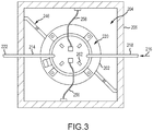
- FIG. 2 is a schematic view of an example cesium trap assembly 200 and FIG. 3 is a top view of the cesium trap assembly 200 taken along section line 3-3.
- the cesium trap assembly 200 includes a removable cesium trap 202 disposed within an interior chamber 204 of an individual shielded cell 206 that is configured to contain radioactive material therein.
- the cell 206 may be coverable via a removable cover 208 depicted in dashed lines in FIG. 2 .
- the cesium trap 202 includes a body 210 at least partially surrounded by a cooling jacket 212 as discussed in further detail below.
- the cesium trap 202 is coupled in flow communication with a sodium line 214 that forms at least a portion of the sodium processing circuit 140 (shown in FIG. 1 ), such that a stream of sodium 216 may be channeled through the body 210.
- Sodium stream 216 may contain, but is not limited to, sodium, cesium, and argon.
- an inlet sodium line 218 extends from the body 210 at a top portion 220 of the cesium trap 202
- an outlet sodium line 222 also extends from the body 210 at the top portion 220.
- the cesium trap 202 is coupled in flow communication with a fixed cooling line 224 such that a stream of coolant 226 may be channeled through the cooling jacket 212.
- An inlet cooling line 228 extends from the cooling jacket 212 proximate a bottom portion 230 of the cesium trap 202 and includes a free end 232.
- the free end 232 is configured to releasably couple in flow communication with the fixed cooling line 224.
- the free end 232 has an enlarged diameter such that the free end 232 may be slidably engaged over and around the fixed cooling line 224.
- the inlet cooling line 228 may be releasably coupled to the fixed cooling line 224 via any other connection that enables the cesium trap 202 to function as described herein.
- An outlet cooling line 234 also extends from the cooling jacket 212 such that the coolant stream 226 may be exhausted into the interior chamber 204.
- the cesium trap 202 is coupled to the cell 206 within the interior chamber 204.
- a base 236 is coupled to the bottom portion 230 and includes at least one opening 238 defined therein.
- the openings 238 correspond to and are configured to slidably engage with locating pins 240 extending from a floor 242 of the cell 206.
- the locating pins 240 include a bullet nose 244 or other tapered tip to facilitate locating of and engagement with the openings 238. Additionally, the locating pins 240 reduce excessive lower cesium trap 202 movement during seismic events.
- the base 236 is sized larger than the cesium trap 202 to increase stability within the cell 206.
- the cesium trap 202 is also coupled within the interior chamber 204 via support anchors 246 configured to support lateral and vertical loads, such as seismic loads.
- the lateral support anchor 246 includes a cell anchor 248 coupled to and extending from a wall 250 of cell and a trap anchor 252 coupled to and extending from cooling jacket 212.
- the cell anchor 248 is releasably coupled to and on top of the trap anchor 252 via a connection member 254.
- the connection member 254 is a captive male fastener located on the cell anchor 248 that has a bullet nose entrance to allow a remote rotational device to be used to unthread it from a corresponding female capture nut located on the trap anchor 252.
- the connection member 254 may be a pin, a bolt, or any other connection member that enables the lateral support anchor 246 to function as described herein.
- the cesium trap 202 is communicatively coupled to a control system, for example, control system 142, via electrical power attachment 256 and instrument control attachment 258 extending from cell 206. Electrical power and instrument control attachments 256 and 258 plug into the cesium trap 202 via at least one receiver 260 disposed at the top portion 220. Additionally, the cesium trap 202 includes at least one lifting eye 262, for example two or four for redundancy, extending from the top portion 220. In one example, lifting eyes 262 are welded to body 210, while in other examples lifting eyes 262 are unitarily formed with body 210. The lifting eyes 262 may be configured to facilitate rotation of the cesium trap 202 once lifted.
- the removal cask 264 Positioned above the cell 206 is a moveable removal cask 264 that facilitates replacing the cesium trap 202 within cell 206.
- the removal cask 264 defines an interior chamber 266 that is configured to contain radioactive material therein.
- a floor valve 268 is positioned above the cell 206 that may be closed after removing the cover 208.
- the removal cask 264 includes a remote lifting tool 270 that releasably couples to the cesium trap 202 and facilities removing the cesium trap 202 from the cell 206.
- lifting tool 270 includes an arm 272 with a plate 274 connected thereto.
- the plate 274 includes at least one hook 276 extending therefrom.
- the hooks 276 may be substantially "J"-shaped and correspond to the lifting eyes 262 disposed on cesium trap 202.
- lifting tool 270 has any other configuration that enables function as described herein.
- removal cask 264 also includes a remote sodium line tool 278 that facilitates crimping and cutting the sodium line 214 as described further below, a remote anchor tool 280 that facilitates decoupling the lateral support anchors as described further below, and a remote attachment tool 282 that facilitates unplugging the electrical power and instrument control attachments 256 and 258 as described further below.
- each tool 270, 278, 280, and 282 are operatively coupled to a control system, for example, control system 142, for remote operation. Additionally, one or more cameras (not shown) are provided to assist remote operation.
- removal cask 264 may include a single tool that combines all of the functions of tools 270, 278, 280, and 282 such that removal cask 264 may function as described herein.
- sodium coolant 106 is circulated through reactor 100 as described above in reference to FIG. 1 .
- fissionable fuel transfers heat to the sodium coolant 106, in addition, volatile fission products such as cesium enter the sodium coolant 106.
- a portion 216 of the sodium coolant 106 is channeled through sodium processing circuit 140, including the inlet and outlet sodium lines 218 and 222 and the cesium trap 202, to, in part, remove the volatile fission products contained therein and reduce any adverse radiological impact.
- cesium trap 202 As the sodium stream 216 is channeled through cesium trap 202, the cesium contained therein is absorbed and filtered out of the sodium stream 216 before being channeled back into the reactor 100. The operation of cesium trap 202 will be discussed in further detail below.
- the cesium traps are fixed within the shielded cells, and as such, once the traps are loaded with the extracted cesium, the entire cesium trap and extracted radioactive cesium are stored in place.
- long term operation of such reactors may produce a number of cesium traps loaded with radioactive cesium, with a number of radioactive shielded cells located in close proximity to the reactor core.
- the above described cesium trap assembly 200 facilitates removal and replacement of the cesium traps 202 that are loaded with radioactive cesium.
- the cesium trap 202 and radioactive cesium therein may be transferred to a more suitable long-term storage location either on-site and/or at a remote facility. Additionally, some of the reactor area surrounding the reactor core may be used for other reactor systems and processes.
- the sodium stream 216 is redirected away from the cesium trap 202 and the remaining sodium within the sodium lines 214 and the cesium trap 202 is allowed to freeze.
- the sodium stream 216 freezes at 208° Fahrenheit (97.8°C), such that turning off electrical heaters of the circuit (not shown) and stopping flow of the sodium stream 216 facilitates freezing the cesium trap 202 over time.
- cooling gas may be circulated through the cooling jacket 212 to increase freezing time.
- the floor valve 268 is installed over the cell 206 and the cover 208 removed from the cell 206 and moved to a temporary storage location on-site.
- the floor valve 268 is closable such that reactor personnel are shielded from the high radiation (gamma) fields from the cesium trap 202 once the cover 208 is removed.
- the removal cask 264 is mated to the floor valve 268 and the floor valve 268 opened to provide access into interior chamber 204 of cell 206 while maintaining containment thereof.
- the floor valve 268, cover 208, and removal cask 264 may all be positionable via a crane (not shown) within the reactor 100 and remotely operable.
- the floor valve 268, cover 208, and removal cask 264 are movable via any other system that enables the cesium trap 202 to be removed and replaced as described herein.
- the cesium trap 202 may be remotely decoupled from the shielded cell 206.
- the sodium lines 214, the lateral support anchors 246, and the power and control attachments 256 and 258 extending to the cesium trap 202 are removed.
- sodium line tool 278 is remotely operated to extend into interior chamber 204 and to decouple the cesium trap 202 from the sodium processing circuit 140.
- the sodium line tool 278 crimps both the inlet and outlet sodium lines 218 and 222 extending from the cesium trap 202 and cuts the sodium lines 218 and 222 adjacent to a crimped portion 284.
- each sodium line 218 and 222 now includes two portions, a first portion 286 that remains extending from cesium trap 202 and a second portion 288 that remains part of the sodium processing circuit 140.
- Anchor tool 280 is remotely operated to extend into interior chamber 204 and decouple the lateral support anchor 246 extending between the cesium trap 202 and the cell 206.
- the anchor tool 280 removes connection member 254, for example, a pin or a bolt, such that trap anchor 252 is decoupled from cell anchor 248.
- Attachment tool 282 is remotely operated to extend into interior chamber 204 and disconnect the electrical power and instrument control attachments 256 and 258 from the cesium trap 202.
- the attachment tool 282 unplugs attachments 256 and 258 from the associated receivers 260.
- the lifting tool 270 extends into interior chamber 204 and is releasably coupled to the cesium trap 202.
- lifting tool 270 rotates and lifts hooks 276 into the corresponding lifting eyes 262 such that cesium trap 202 is movable.
- the lifting tool 270 vertically lifts the cesium trap 202 away from the cell 206 and into the removal cask 264 such that the base 236 slidably disengages with the locating pins 240.
- the inlet cooling line 228 is also decoupled from the fixed cooling line 224 as the free end 232 automatically slidably disengages with the fixed cooling line 224.
- the inlet cooling line 228 may be cut to decouple the cesium trap 202, similar to the procedure with the sodium lines 214. Additionally, the trap anchor 252 is positioned above the cell anchor 248 so that the cesium trap 202 may be vertically lifted. Once the cesium trap 202 is within the removal cask 264, the cesium trap 202 with cesium therein and the removal cask 264 may be moved to another location, either on-site or to a remote site, for further processing and/or long-term storage. Additionally, once the radioactive cesium is removed, the cell 206 may be directly accessed for installing a new cesium trap 202.
- a new replacement cesium trap such as cesium trap 202 that is similar to the cesium trap removed but without any cesium therein, may be inserted into the shielded cell 206 using typical personnel and rigging methods on the overhead crane.
- the replacement cesium trap 202 is releasably coupled to a lifting tool, for example, the lifting tool 270 via corresponding hooks 276 and lifting eyes 262 such that the replacement cesium trap 202 may be placed into the interior chamber 204 of the cell 206.
- the replacement cesium trap 202 is coupled to a different lifting tool, such as the crane within the reactor 100.
- the base 236 is simultaneously aligned with the locating pins 240 to position the replacement cesium trap 202 along the floor 242.
- the locating pins 240 By aligning the locating pins 240, the free end 232 of the inlet cooling line 228 is automatically slidably engaged with the fixed cooling line 224.
- the replacement cesium trap 202 is attached to the shielded cell 206. This attachment may be performed with direct access to the cell because no radioactive cesium is present therein.
- the sodium lines 214, the lateral support anchors 246, and the power and control attachments 256 and 258 are extended to the cesium trap 202.
- the replacement cesium trap 202 is coupled to the sodium processing circuit 140.
- the first portion 286 of the sodium line 214 extending from the cesium trap 202 is aligned and welded to the second portion 288 of the sodium line extending from the sodium processing circuit, thus forming the inlet and outlet sodium lines 218 and 222.
- the cell anchor 248 is coupled to the trap anchor 252 via a connection member 254, such as a pin or a bolt, forming the lateral support anchor 246.
- the electrical power and instrument control attachments 256 and 258 are connected, via plugging, to corresponding receivers 260.
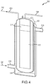
- FIG. 4 is a perspective view of an example cesium trap 300 that includes a body 302 at least partially surrounded by a cooling jacket 304, similar to the cesium trap described above.
- the body 302 includes an inlet line 306 and an outlet line 308 such that a stream of sodium 310 is channeled therethrough.
- the cesium trap 300 includes a column of active material 312.
- the active material is Reticulated Vitreous Carbon (RVC) that adsorbs cesium and removes the cesium from the sodium stream 310.
- RVC Reticulated Vitreous Carbon
- Body 302 also includes a filter 314 that filters RVC particles that may become entrained within the sodium stream 310.
- the cooling jacket 304 includes an inlet line 316 and an outlet line 318 such that a stream of coolant 320 is channeled therethrough.
- the coolant 320 is nitrogen that reduces the operating temperature of the cesium trap 300.
- the inlet line 306 and /or the outlet line 308 may extend into the cesium trap 300 such that the level of sodium therein to be lowered in preparation for disposal.
- the cesium trap 300 may include a capped line (not shown) that facilitates draining the sodium therein in a purpose built hot cell preparation facility and inserting material to reduce the chemical reactivity of sodium, such as lead, in preparation for disposal.
- the filter 314 that prevents RVC from exiting the trap has a mean pore size of from 40 to 160 ⁇ m.
- a filter 314 having a mean pore size from a lower limit of any of 40, 50, 60, 70, 80, or even 90 ⁇ m to an upper limit of any of 100, 110, 120, 130, 140, 150 or even 160 ⁇ m are contemplated.
- the filter 314 may be any appropriate filter media.
- the filter 314 is a sintered metal filter.
- the sintered metal filter may be made of one or more of stainless steel, Hastelloy®, Monel®, Inconel®, nickel, HT-9, and titanium to name but a few possible metals.
- other filter types and filter media may be used having the mean pore size as described above.
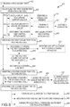
- FIG. 5 is a flowchart illustrating a method 400 of replacing a cesium trap.
- the method 400 includes a first cesium trap at least partially containing cesium therein being frozen 402.
- the first cesium trap is decoupled 404 from a shielded cell and then removed 406 from the shielded cell.
- a second cesium trap is inserted 408 into the shielded cell and then attached 410 to the shielded cell.
- Decoupling 404 the first cesium trap includes removing lateral support anchors, sodium lines, and power and electrical connections extending thereto.
- the first cesium trap may be remotely decoupled 412 from a lateral support anchor.
- a connection member may be removed 414 between a cell anchor and a trap anchor.
- the first cesium trap may be remotely decoupled 416 from a sodium processing circuit.
- a sodium line is crimped 418 and cut 420.
- the first cesium trap may be also remotely disconnected 422 from electrical power and instrument control attachments. As such, the electrical power and instrument control attachments are unplugged 424 from a corresponding receiver.
- Removing 406 the first cesium trap includes releasably coupling 426 the first cesium trap to a lifting tool.
- the lifting tool may include a hook that is rotated and lifted 428 into a corresponding lifting eye of the cesium trap.
- the first cesium trap is then lifted 430 by the lifting tool out of the shielded shell.
- the lifting operation may also simultaneously decouple 432 a cooling line inlet from a fixed cooling line.
- Inserting 408 the second cesium trap includes coupling 434 the second cesium trap to a lifting tool, for example, via a hook extending from the lifting tool and a corresponding lifting eye of the cesium trap.
- the second cesium trap is then placed 436 into the shielded cell by the lifting tool, and simultaneously a base of the second cesium trap is aligned 438 with at least one locating pin extending from the floor of the shielded cell.
- Attaching 410 the second cesium trap includes re-coupling lateral support anchors, sodium lines, and power and electrical connections thereto.
- a cell anchor may be coupled 440 to a trap anchor forming a lateral support anchor within the cell.
- a first sodium line of the second cesium trap may be welded 442 to a second sodium line of the sodium processing circuit forming the sodium lines of the second cesium trap.
- the electrical power and instrument control attachments may be connected 444 into a corresponding receiver.
Landscapes
- Physics & Mathematics (AREA)
- Engineering & Computer Science (AREA)
- Plasma & Fusion (AREA)
- General Engineering & Computer Science (AREA)
- High Energy & Nuclear Physics (AREA)
- Manufacture And Refinement Of Metals (AREA)
- Solid-Sorbent Or Filter-Aiding Compositions (AREA)
- Monitoring And Testing Of Nuclear Reactors (AREA)
- Structure Of Emergency Protection For Nuclear Reactors (AREA)
- Vaporization, Distillation, Condensation, Sublimation, And Cold Traps (AREA)
Claims (14)
- Verfahren (400) zum Ersetzen einer Cäsiumfalle, das Verfahren gekennzeichnet durch:Gefrieren (402) einer ersten Cäsiumfalle mindestens teilweise, die Cäsium darin enthält, wobei die erste Cäsiumfalle innerhalb einer abgeschirmten Zelle lokalisiert ist;Entkoppeln der ersten Cäsiumfalle von der abgeschirmten Zelle;Entfernen (406) der ersten Cäsiumfalle aus der abgeschirmten Zelle;Einführen (408) einer zweiten Cäsiumfalle in die abgeschirmte Zelle; undAnschließen (410) der zweiten Cäsiumfalle an die abgeschirmte Zelle.
- Verfahren nach Anspruch 1, wobei Entkoppeln der ersten Cäsiumfalle mindestens eines des Folgenden umfasst:entferntes Entkoppeln (412) mindestens einer lateralen Stützverankerung, die sich zwischen der ersten Cäsiumfalle und der abgeschirmten Zelle erstreckt;entferntes Entkoppeln (416) der ersten Cäsiumfalle aus einem Natriumverarbeitungskreis; undentferntes Trennen (422) von elektrischen Strom- und Instrumentensteuerungsanschlüssen, die sich zwischen der ersten Cäsiumfalle und der abgeschirmten Zelle erstrecken.
- Verfahren nach Anspruch 2, wobei entferntes Entkoppeln der mindestens einen lateralen Stützverankerung Entfernen (414) eines Verbindungsglieds umfasst, das eine Zellenverankerung, die sich aus der abgeschirmten Zelle erstreckt, mit einer Fallenverankerung koppelt, die sich aus der ersten Cäsiumfalle erstreckt.
- Verfahren nach Anspruch 2, wobei entferntes Entkoppeln der ersten Cäsiumfalle aus einem Natriumverarbeitungskreis Folgendes umfasst:Quetschen (418) mindestens einer Natriumleitung, die sich aus der ersten Cäsiumfalle erstreckt; undSchneiden (420) der mindestens einen Natriumleitung derartig dem gequetschten Abschnitt benachbart, dass sich ein erster Abschnitt der mindestens einen Natriumleitung aus einem oberen Abschnitt der ersten Cäsiumfalle erstreckt und ein zweiter Abschnitt der mindestens einen Natriumleitung Teil des Natriumverarbeitungskreises bleibt.
- Verfahren nach Anspruch 2, wobei entferntes Trennen von elektrischen Strom- und Instrumentensteuerungsanschlüssen Lösen (424) mindestens eines elektrischen Stromanschlusses oder eines Instrumentensteuerungsanschlusses aus einer entsprechenden Aufnahme umfasst, die auf einem oberen Abschnitt der ersten Cäsiumfalle angeordnet ist.
- Verfahren nach Anspruch 1, wobei Entfernen der ersten Cäsiumfalle Folgendes umfasst:lösbares Koppeln (426) der ersten Cäsiumfalle mit einem Hebewerkzeug; undHeben (430), über das Hebewerkzeug, der ersten Cäsiumfalle derartig aus der abgeschirmten Zelle, dass eine Basis der ersten Cäsiumfalle verschiebbar von mindestens einem Führungsstift ausrastet, der sich von einem Boden der abgeschirmten Zelle erstreckt.
- Verfahren nach Anspruch 6, weiterhin Entkoppeln (432) eines Kühlleitungseinlasses, der sich aus der ersten Cäsiumfalle erstreckt, von einer festen Kühlleitung, die sich aus der abgeschirmten Zelle erstreckt, über die Hebeoperation umfassend.
- Verfahren nach Anspruch 1, wobei Einführen der zweiten Cäsiumfalle Folgendes umfasst:lösbares Koppeln (434) der zweiten Cäsiumfalle mit einem Hebewerkzeug, wobei das Hebewerkzeug mindestens einen Haken umfasst und die zweite Cäsiumfalle mindestens einen entsprechenden Hebering umfasst;Platzieren (436), über das Hebewerkzeug, der zweiten Cäsiumfalle in der abgeschirmten Zelle; undgleichzeitiges Ausrichten (438) einer Basis der zweiten Cäsiumfalle mit mindestens einem Führungsstift, der sich von einem Boden der abgeschirmten Zelle erstreckt.
- Verfahren nach Anspruch 1, wobei Anschließen der zweiten Cäsiumfalle mindestens eines des Folgenden umfasst:Koppeln (440) einer Zellenverankerung, die sich aus der abgeschirmten Zelle erstreckt, mit einer Fallenverankerung, die sich aus der zweiten Cäsiumfalle erstreckt, wobei mindestens eine laterale Stützverankerung ausgebildet wird, die sich zwischen der ersten Cäsiumfalle und der abgeschirmten Zelle erstreckt;Schweißen (442) mindestens einer ersten Natriumleitung, die sich aus der zweiten Cäsiumfalle erstreckt, an mindestens eine zweite Natriumleitung, die sich aus einem Natriumverarbeitungskreis erstreckt; undVerbinden (444) von elektrischen Strom- und Instrumentensteuerungsanschlüssen durch Einstecken der Anschlüsse in eine entsprechende Aufnahme, die auf einem oberen Abschnitt der zweiten Cäsiumfalle angeordnet ist.
- Entfernbare Cäsiumfalle (202) zur Aufnahme in einer abgeschirmten Zelle, die entfernbare Cäsiumfalle Folgendes umfassend:einen Körper (210), einen oberen Abschnitt (220) umfassend, wobei der Körper einen Filter und ein aktives Material umschließt, das eingerichtet ist, um Cäsium aus einem Natriumstrom zu entfernen;einen Kühlmantel (212), der im Wesentlichen um den Körper herum angeordnet ist;mindestens eine erste Natriumleitung (214), die sich aus dem oberen Abschnitt erstreckt, wobei die mindestens eine erste Natriumleitung in Strömungskommunikation mit einer entsprechenden mindestens einen zweiten Natriumleitung (222) eines Natriumverarbeitungskreises koppelbar ist; undmindestens eine Fallenverankerung (252), die sich aus dem Kühlmantel erstreckt, wobei die Fallenverankerung lösbar mit mindestens einer entsprechenden Zellenverankerung (248) koppelbar ist, die sich aus der abgeschirmten Zelle erstreckt, um so mindestens eine laterale Stützverankerung (246) auszubilden.
- Entfernbare Cäsiumfalle nach Anspruch 10, weiterhin mindestens einen Hebering (262) umfassend, der auf dem oberen Abschnitt angeordnet ist, wobei der mindestens eine Hebering eingerichtet ist, um ein Hebewerkzeug (276) zum Platzieren der Cäsiumfalle in und zum Entfernen der entfernbaren Cäsiumfalle aus der abgeschirmten Zelle aufzunehmen.
- Entfernbare Cäsiumfalle nach Anspruch 10, weiterhin eine Einlasskühlleitung (228) umfassend, die sich von einem Bodenabschnitt des Kühlmantels erstreckt, wobei die Einlasskühlleitung ein freies Ende aufweist, das in Strömungskommunikation mit einer entsprechenden festen Kühlleitung in der abgeschirmten Zelle lösbar koppelbar ist.
- Entfernbare Cäsiumfalle nach Anspruch 10, weiterhin mindestens eine Aufnahme (260) umfassend, die auf dem oberen Abschnitt angeordnet ist, wobei die mindestens eine Aufnahme derartig eingerichtet ist, dass elektrische Strom- und Instrumentensteuerungsanschlüsse in die mindestens eine Aufnahme lösbar einsteckbar sind.
- Entfernbare Cäsiumfalle nach Anspruch 10, weiterhin eine Basis (236) umfassend, die mit einem Bodenabschnitt des Körpers gekoppelt ist, wobei mindestens eine Öffnung innerhalb der Basis derartig definiert ist, dass die Basis innerhalb eines Bodens der abgeschirmten Zelle durch Einrasten von mindestens einem entsprechenden Führungsstift (240) der abgeschirmten Zelle in die mindestens eine Öffnung positionierbar ist.
Applications Claiming Priority (2)
| Application Number | Priority Date | Filing Date | Title |
|---|---|---|---|
| US201762478419P | 2017-03-29 | 2017-03-29 | |
| PCT/US2018/025216 WO2018183725A1 (en) | 2017-03-29 | 2018-03-29 | Method of replacing cesium trap and cesium trap assembly thereof |
Publications (2)
| Publication Number | Publication Date |
|---|---|
| EP3602574A1 EP3602574A1 (de) | 2020-02-05 |
| EP3602574B1 true EP3602574B1 (de) | 2021-07-21 |
Family
ID=61468155
Family Applications (1)
| Application Number | Title | Priority Date | Filing Date |
|---|---|---|---|
| EP18734318.1A Active EP3602574B1 (de) | 2017-03-29 | 2018-03-29 | Verfahren zum ersetzen einer cäsiumfalle und cäsiumfallenanordnung dafür |
Country Status (8)
| Country | Link |
|---|---|
| US (2) | US11152127B2 (de) |
| EP (1) | EP3602574B1 (de) |
| JP (2) | JP7123966B2 (de) |
| KR (2) | KR102558295B1 (de) |
| CN (2) | CN207038182U (de) |
| CA (1) | CA3056800A1 (de) |
| RU (1) | RU2763773C2 (de) |
| WO (1) | WO2018183725A1 (de) |
Families Citing this family (10)
| Publication number | Priority date | Publication date | Assignee | Title |
|---|---|---|---|---|
| US10685750B2 (en) | 2016-03-08 | 2020-06-16 | TerraPower, LLC. | Fission product getter |
| US10636532B2 (en) | 2016-05-20 | 2020-04-28 | Terrapower, Llc | Sodium cesium vapor trap system and method |
| CN207038182U (zh) * | 2017-03-29 | 2018-02-23 | 泰拉能源有限责任公司 | 铯收集器 |
| CA3143290A1 (en) | 2019-08-23 | 2021-03-04 | Terrapower, Llc | Sodium vaporizer and method for use of sodium vaporizer |
| CN111192701B (zh) * | 2020-01-09 | 2021-11-02 | 中国原子能科学研究院 | 一种一体化入口接管 |
| CN115019991A (zh) * | 2022-06-10 | 2022-09-06 | 清华大学 | 收集装置 |
| EP4555539A1 (de) | 2022-07-13 | 2025-05-21 | TerraPower, LLC | Oxidation von cesium als verfahren zur entfernung von cesiumdampf aus abdeckgas in kernreaktoren |
| US12562289B2 (en) | 2023-01-20 | 2026-02-24 | Abilene Christian University | Fission product trap for salt pipe and pump shaft seals and methods of use thereof |
| US12012827B1 (en) | 2023-09-11 | 2024-06-18 | Natura Resources LLC | Nuclear reactor integrated oil and gas production systems and methods of operation |
| US12500006B2 (en) * | 2023-12-05 | 2025-12-16 | Natura Resources LLC | Deployment method and systems for molten salt reactors |
Citations (3)
| Publication number | Priority date | Publication date | Assignee | Title |
|---|---|---|---|---|
| JPS6043447A (ja) * | 1983-08-17 | 1985-03-08 | Hitachi Ltd | 液体金属精製装置 |
| US4587083A (en) * | 1983-08-10 | 1986-05-06 | The United States Of America As Represented By The United States Department Of Energy | Method for removing cesium from a nuclear reactor coolant |
| US5030411A (en) * | 1988-11-14 | 1991-07-09 | Westinghouse Electric Corp. | Removal of impurities from coolant of a nuclear reactor |
Family Cites Families (99)
| Publication number | Priority date | Publication date | Assignee | Title |
|---|---|---|---|---|
| US2745552A (en) * | 1953-09-02 | 1956-05-15 | Warren H Bruggeman | Filter with fractional crystallization means |
| GB949117A (en) * | 1961-12-20 | 1964-02-12 | Atomic Energy Authority Uk | Improvements in or relating to nuclear reactors |
| US4040903A (en) | 1964-07-21 | 1977-08-09 | The United States Of America As Represented By The United States Energy Research And Development Administration | Thermionic energy converters |
| GB1141083A (en) | 1965-06-28 | 1969-01-22 | North American Aviation Inc | Method of converting thermal energy directly to electrical energy |
| GB1285088A (en) * | 1969-12-18 | 1972-08-09 | Atomic Energy Authority Uk | Cold traps for liquid metal |
| US3618770A (en) * | 1970-02-04 | 1971-11-09 | Atomic Energy Commission | Cold trap |
| JPS5015204B1 (de) * | 1970-05-29 | 1975-06-03 | ||
| NL172604C (nl) | 1970-07-23 | 1983-09-16 | Interatom | Inrichting voor het continu afscheiden van metaaldampen of metaalaerosolen in vloeibare vorm uit gassen, in het bijzonder van natriumdamp of -druppeltjes uit het schutgas van een natriumgekoelde kernenergie-installatie. |
| US4010068A (en) * | 1972-09-28 | 1977-03-01 | Westinghouse Electric Corporation | Removal of radioactive contamination from a nuclear reactor coolant |
| US3993453A (en) | 1973-05-09 | 1976-11-23 | General Electric Company | Getter for nuclear fuel elements |
| US4117396A (en) | 1974-01-21 | 1978-09-26 | Westinghouse Electric Corp. | Sensor for thermally ionizable particles and/or vapors |
| JPS5551396B2 (de) | 1974-03-25 | 1980-12-24 | ||
| JPS51107212A (de) | 1975-03-19 | 1976-09-22 | Tokyo Shibaura Electric Co | |
| US4119488A (en) | 1975-04-10 | 1978-10-10 | S.A.E.S. Getters S.P.A. | Nuclear reactor fuel element employing Zr2 Ni as a getter metal |
| JPS5814494B2 (ja) * | 1975-05-30 | 1983-03-19 | 三菱重工業株式会社 | エキタイチユウノイブツホシユウソウチ |
| US3979498A (en) * | 1975-08-06 | 1976-09-07 | The United States Of America As Represented By The United States Energy Research And Development Administration | Recovery of cesium and palladium from nuclear reactor fuel processing waste |
| US4047101A (en) | 1976-01-08 | 1977-09-06 | Westinghouse Electric Corporation | Filament for alkali metal ionization detector |
| US4095171A (en) | 1976-04-07 | 1978-06-13 | Westinghouse Electric Corp. | Alkali metal ionization detector |
| US4047040A (en) | 1976-05-06 | 1977-09-06 | General Electric Company | Gridded ionization chamber |
| JPS52138412A (en) * | 1976-05-15 | 1977-11-18 | Doryokuro Kakunenryo | Vapour trap for liquid metal |
| US4131511A (en) | 1977-02-04 | 1978-12-26 | Combustion Engineering, Inc. | Nuclear fuel element |
| US4121458A (en) | 1977-02-24 | 1978-10-24 | Westinghouse Electric Corp. | Reliable dynamoelectric machine condition monitor |
| NL7802116A (nl) | 1977-03-14 | 1978-09-18 | Getters Spa | Alkalimetaaldampgenerator. |
| SU693868A1 (ru) | 1977-08-01 | 1984-08-07 | Институт Физики Ан Латвсср | Способ непрерывной очистки жидкометаллического расплава в контуре циркул ции |
| DE2746159A1 (de) | 1977-10-14 | 1979-04-19 | Interatom | Kernenergieanlage mit einrichtung zur kuehlmittelreinigung |
| US4257847A (en) | 1978-10-06 | 1981-03-24 | The United States Of America As Represented By The United States Department Of Energy | Nuclear breeder reactor fuel element with axial tandem stacking and getter |
| FR2438840A1 (fr) | 1978-10-11 | 1980-05-09 | Hitachi Ltd | Detecteur d'ionisation du sodium |
| US4325029A (en) | 1979-09-10 | 1982-04-13 | Westinghouse Electric Corp. | Alkali ionization detector |
| DE3144974C2 (de) * | 1981-11-12 | 1986-01-09 | Kernforschungszentrum Karlsruhe Gmbh, 7500 Karlsruhe | Verfahren zur Abtrennung von Aktinoidenionen aus wäßrigen, basischen, carbonathaltigen Lösungen |
| GB2113901B (en) * | 1982-01-19 | 1986-06-11 | Us Energy | Apparatus and method for reprocessing and separating spent nuclear fuels |
| JPS59190694A (ja) * | 1983-04-13 | 1984-10-29 | 株式会社日立製作所 | 放射性セシウムトラツプ |
| US4853177A (en) | 1983-05-06 | 1989-08-01 | The Babcock & Wilcox Company | Void plug for annular fuel pellets |
| FR2550681B1 (fr) | 1983-08-12 | 1985-12-06 | Centre Nat Rech Scient | Source d'ions a au moins deux chambres d'ionisation, en particulier pour la formation de faisceaux d'ions chimiquement reactifs |
| FR2557806B1 (fr) * | 1984-01-05 | 1986-04-25 | Electricite De France | Piege froid pour epuration de sodium liquide contenant des impuretes |
| US4578242A (en) | 1984-07-03 | 1986-03-25 | General Motors Corporation | Metallothermic reduction of rare earth oxides |
| JPS61228382A (ja) | 1985-04-03 | 1986-10-11 | 日本核燃料開発株式会社 | 核燃料要素 |
| US4710343A (en) | 1985-11-27 | 1987-12-01 | The United States Of America As Represented By The United States Department Of Energy | Nuclear breeder reactor fuel element with silicon carbide getter |
| US4719355A (en) | 1986-04-10 | 1988-01-12 | Texas Instruments Incorporated | Ion source for an ion implanter |
| FR2603497B1 (fr) * | 1986-09-10 | 1991-10-04 | Commissariat Energie Atomique | Piege froid de purification des metaux liquides contenant des impuretes dissoutes |
| JPH0823598B2 (ja) * | 1987-11-09 | 1996-03-06 | 株式会社日立製作所 | 放射性物質除去装置 |
| FR2624032B1 (fr) * | 1987-12-03 | 1991-05-10 | Commissariat Energie Atomique | Piege froid pour la purification d'un metal liquide comportant des zones de piegeage separees |
| US4845364A (en) | 1988-02-29 | 1989-07-04 | Battelle Memorial Institute | Coaxial reentrant ion source for surface mass spectroscopy |
| JPH01232298A (ja) * | 1988-03-11 | 1989-09-18 | Hitachi Ltd | 精製装置 |
| DE3908265A1 (de) | 1989-03-14 | 1990-09-20 | Leybold Ag | Chargiervorrichtung fuer schmelzanlagen |
| SU1739782A1 (ru) * | 1989-09-25 | 1994-01-15 | В.С. Наумов | Способ регенерации холодной ловушки |
| JP2863939B2 (ja) * | 1990-01-08 | 1999-03-03 | 株式会社日立製作所 | トリチウムの透過低減装置 |
| JPH0469592A (ja) | 1990-07-09 | 1992-03-04 | Chugoku Electric Power Co Inc:The | 核燃料要素 |
| JPH04122897A (ja) | 1990-09-14 | 1992-04-23 | Hitachi Ltd | 不純物除去装置 |
| JP2995582B2 (ja) | 1990-11-29 | 1999-12-27 | セイコーインスツルメンツ株式会社 | 液体金属イオン源 |
| JPH04286996A (ja) | 1991-03-15 | 1992-10-12 | Hitachi Ltd | 不純物除去装置 |
| EP0508715A1 (de) | 1991-04-09 | 1992-10-14 | General Electric Company | Getter enthaltendes Kernbrennelement |
| US6084147A (en) * | 1995-03-17 | 2000-07-04 | Studsvik, Inc. | Pyrolytic decomposition of organic wastes |
| US5820681A (en) | 1995-05-03 | 1998-10-13 | Chorus Corporation | Unibody crucible and effusion cell employing such a crucible |
| FR2742257B1 (fr) * | 1995-12-12 | 1998-01-30 | Comurhex | Procede de valorisation, sous forme d'acide nitrique, des ions nitrates contenus dans les effluents de l'industrie nucleaire |
| JP3031858B2 (ja) | 1996-03-13 | 2000-04-10 | 核燃料サイクル開発機構 | Na中の不純物分析装置及びこれを用いたNa中の不純物分析方法 |
| US6030458A (en) | 1997-02-14 | 2000-02-29 | Chorus Corporation | Phosphorus effusion source |
| RU2123732C1 (ru) * | 1997-05-05 | 1998-12-20 | Государственный научный центр Российской Федерации Научно-исследовательский институт атомных реакторов | Способ переработки натриевого теплоносителя ядерного реактора |
| US6117208A (en) | 1998-04-23 | 2000-09-12 | Sharma; Ram A. | Molten salt process for producing titanium or zirconium powder |
| US6069362A (en) | 1998-05-14 | 2000-05-30 | The University Of Akron | Multi-density and multi-atomic number detector media for applications |
| RU2138867C1 (ru) * | 1998-07-07 | 1999-09-27 | Государственный научный центр РФ "Научно-исследовательский институт атомных реакторов" | Способ отмывки оборудования от натрия |
| US6602919B1 (en) | 1999-09-17 | 2003-08-05 | Ut-Battelle Llc | Method for preparing hydrous zirconium oxide gels and spherules |
| JP2001272493A (ja) | 2000-03-28 | 2001-10-05 | Tokyo Inst Of Technol | 鉛系金属循環装置 |
| US6840085B1 (en) | 2001-09-18 | 2005-01-11 | Robert J. Kolaja | Photoionization detector with multiple ionization cells |
| KR20030059708A (ko) | 2002-01-04 | 2003-07-10 | 필터레이 화이버 옵틱스 인코퍼레이티드 | 세슘 공급 장치 및 방법 |
| KR20030085198A (ko) | 2002-04-29 | 2003-11-05 | 필터레이 화이버 옵틱스 인코퍼레이티드 | 세슘 공급장치 및 방법 |
| US8123862B2 (en) | 2003-08-15 | 2012-02-28 | Semiconductor Energy Laboratory Co., Ltd. | Deposition apparatus and manufacturing apparatus |
| RU2269171C1 (ru) * | 2004-07-15 | 2006-01-27 | Федеральное государственное унитарное предприятие "Государственный научный центр Российской Федерации - Научно-исследовательский институт атомных реакторов" | Способ регенерации холодных ловушек примесей натриевого теплоносителя |
| ITMI20041736A1 (it) | 2004-09-10 | 2004-12-10 | Getters Spa | Miscele per l'evaporazione del litio e dispensatori di litio |
| ITMI20042279A1 (it) | 2004-11-24 | 2005-02-24 | Getters Spa | Sistema dispensatore di metalli alcalini in grado di dispensare quantita' elevate di metalli |
| FI118803B (fi) | 2005-04-22 | 2008-03-31 | Beneq Oy | Lähde, järjestely lähteen asentamiseksi sekä menetelmä lähteen asentamiseksi ja poistamiseksi |
| WO2007135870A1 (ja) | 2006-05-19 | 2007-11-29 | Ulvac, Inc. | 有機蒸着材料用蒸着装置、有機薄膜の製造方法 |
| CN101168128A (zh) | 2006-10-25 | 2008-04-30 | 刘芬 | 复合金属氧化物催化剂及其制备方法和用途 |
| RU2328783C1 (ru) | 2006-12-18 | 2008-07-10 | Федеральное государственное унитарное предприятие Научно-исследовательский институт Научно-производственное объединение "Луч" | Микротвэл ядерного реактора |
| JP5376764B2 (ja) | 2007-03-19 | 2013-12-25 | フタムラ化学株式会社 | 吸油性連通多孔質構造体 |
| US8097164B2 (en) * | 2007-11-08 | 2012-01-17 | Electric Power Research Institute, Inc. | Process for preparing magnetic particles for selectively removing contaminants from solution |
| JP4936492B2 (ja) | 2008-03-25 | 2012-05-23 | 国立大学法人大阪大学 | 放電イオン化電流検出器 |
| CN101315815B (zh) * | 2008-04-28 | 2011-06-08 | 吕应中 | 快速增殖与转化核燃料的方法与装置 |
| FR2933227B1 (fr) * | 2008-06-25 | 2010-07-30 | Commissariat Energie Atomique | Procede de traitement d'une structure contenant du sodium et une matiere radioactive |
| KR101288610B1 (ko) | 2008-07-24 | 2013-07-22 | 주식회사 만도 | 차량용 게이트웨이 전자제어장치 및 그의 주행정보기록방법 |
| JP5551396B2 (ja) | 2009-08-31 | 2014-07-16 | 東レエンジニアリング株式会社 | 検査用プローブおよび検査用プローブの製造方法 |
| US8457271B2 (en) * | 2009-10-30 | 2013-06-04 | Babcock & Wilcox Canada Ltd. | Radioactive debris trap |
| CN101783190A (zh) * | 2010-03-09 | 2010-07-21 | 中国原子能科学研究院 | 钠冷快堆换料用旋转定位装置 |
| US8502158B1 (en) | 2010-04-07 | 2013-08-06 | Polimaster IP Solutions LLC | Distributed system for radiation detection utilizing multiple clustered detectors |
| JP2012032250A (ja) | 2010-07-30 | 2012-02-16 | Hitachi-Ge Nuclear Energy Ltd | 高速増殖炉カバーガス系のナトリウム凝縮型除去装置 |
| US20130010915A1 (en) | 2011-07-08 | 2013-01-10 | Battelle Energy Alliance, Llc | Reactor fuel elements and related methods |
| CN202519317U (zh) * | 2012-04-11 | 2012-11-07 | 内蒙古工业大学 | 一种从钠渣中连续回收金属钠的装置 |
| FR2992976B1 (fr) | 2012-07-04 | 2014-07-18 | Riber | Dispositif d'evaporation pour appareil de depot sous vide et appareil de depot sous vide comprenant un tel dispositif d'evaporation |
| JP6041433B2 (ja) | 2012-10-30 | 2016-12-07 | 有冨 正憲 | 汚染物質処理装置 |
| US9178103B2 (en) | 2013-08-09 | 2015-11-03 | Tsmc Solar Ltd. | Apparatus and method for forming chalcogenide semiconductor absorber materials with sodium impurities |
| JP6101669B2 (ja) | 2013-12-16 | 2017-03-22 | 株式会社日本自動車部品総合研究所 | ガスセンサ |
| US9302226B2 (en) | 2014-05-05 | 2016-04-05 | Ge-Hitachi Nuclear Energy Americas Llc | Salt filtration system and method of removing a radioactive material from a gas using the same |
| US9341596B1 (en) | 2014-12-22 | 2016-05-17 | International Business Machines Corporation | Annular gas ionization delta E-E detector |
| US10184168B2 (en) | 2015-01-20 | 2019-01-22 | Kennametal Inc. | IMC evaporator boat-thermal insulation cartridge assembly |
| KR101585933B1 (ko) * | 2015-08-13 | 2016-01-18 | 한국지질자원연구원 | 다종 이온 회수 시스템 |
| JP6043447B1 (ja) | 2016-02-10 | 2016-12-14 | ニューロング株式会社 | 把手紐保留装置 |
| US10685750B2 (en) | 2016-03-08 | 2020-06-16 | TerraPower, LLC. | Fission product getter |
| US9921184B2 (en) | 2016-05-20 | 2018-03-20 | Terrapower, Llc | Sodium-cesium ionization detector |
| US10636532B2 (en) | 2016-05-20 | 2020-04-28 | Terrapower, Llc | Sodium cesium vapor trap system and method |
| CN207038182U (zh) * | 2017-03-29 | 2018-02-23 | 泰拉能源有限责任公司 | 铯收集器 |
-
2017
- 2017-06-15 CN CN201720696684.2U patent/CN207038182U/zh not_active Expired - Fee Related
-
2018
- 2018-03-29 CN CN201880019493.XA patent/CN110431638A/zh active Pending
- 2018-03-29 RU RU2019132252A patent/RU2763773C2/ru active
- 2018-03-29 EP EP18734318.1A patent/EP3602574B1/de active Active
- 2018-03-29 WO PCT/US2018/025216 patent/WO2018183725A1/en not_active Ceased
- 2018-03-29 JP JP2019553528A patent/JP7123966B2/ja active Active
- 2018-03-29 CA CA3056800A patent/CA3056800A1/en active Pending
- 2018-03-29 KR KR1020197030136A patent/KR102558295B1/ko active Active
- 2018-03-29 KR KR1020237024320A patent/KR102623264B1/ko active Active
- 2018-03-29 US US16/498,665 patent/US11152127B2/en active Active
-
2021
- 2021-09-20 US US17/479,116 patent/US11842819B2/en active Active
-
2022
- 2022-08-10 JP JP2022128074A patent/JP7430225B2/ja active Active
Patent Citations (3)
| Publication number | Priority date | Publication date | Assignee | Title |
|---|---|---|---|---|
| US4587083A (en) * | 1983-08-10 | 1986-05-06 | The United States Of America As Represented By The United States Department Of Energy | Method for removing cesium from a nuclear reactor coolant |
| JPS6043447A (ja) * | 1983-08-17 | 1985-03-08 | Hitachi Ltd | 液体金属精製装置 |
| US5030411A (en) * | 1988-11-14 | 1991-07-09 | Westinghouse Electric Corp. | Removal of impurities from coolant of a nuclear reactor |
Non-Patent Citations (2)
| Title |
|---|
| CHANDRAN K ET AL: "Performance testing of in-sodium sensors and simulated experiments in, sodium chemistry loop", NUCLEAR ENGINEERING AND DESIGN, vol. 268, 22 November 2013 (2013-11-22), pages 1 - 9, XP028611661, ISSN: 0029-5493, DOI: 10.1016/J.NUCENGDES.2013.11.075 * |
| SOBOLEV A M ET AL: "PURIFICATION OF THE COOLANT OF FAST REACTORS FROM CESIUM", ATOMIC ENERGY, SPRINGER, NEW YORK, NY, US, vol. 72, no. 3, 1 March 1992 (1992-03-01), pages 220 - 224, XP000358374, ISSN: 1063-4258, DOI: 10.1007/BF00761242 * |
Also Published As
| Publication number | Publication date |
|---|---|
| RU2019132252A (ru) | 2021-04-29 |
| KR102623264B1 (ko) | 2024-01-09 |
| JP7430225B2 (ja) | 2024-02-09 |
| JP2022145908A (ja) | 2022-10-04 |
| CA3056800A1 (en) | 2018-10-04 |
| JP2020512562A (ja) | 2020-04-23 |
| KR20230113830A (ko) | 2023-08-01 |
| RU2763773C2 (ru) | 2022-01-11 |
| US20220005621A1 (en) | 2022-01-06 |
| KR102558295B1 (ko) | 2023-07-20 |
| US11842819B2 (en) | 2023-12-12 |
| RU2019132252A3 (de) | 2021-07-16 |
| EP3602574A1 (de) | 2020-02-05 |
| CN207038182U (zh) | 2018-02-23 |
| JP7123966B2 (ja) | 2022-08-23 |
| US11152127B2 (en) | 2021-10-19 |
| US20200105428A1 (en) | 2020-04-02 |
| WO2018183725A1 (en) | 2018-10-04 |
| CN110431638A (zh) | 2019-11-08 |
| KR20190139870A (ko) | 2019-12-18 |
Similar Documents
| Publication | Publication Date | Title |
|---|---|---|
| US11842819B2 (en) | Method for replacing a cesium trap and cesium trap assembly thereof | |
| US11887739B2 (en) | Nuclear reactor refueling methods and apparatuses | |
| AU2013218764B2 (en) | Integral molten salt reactor | |
| CN103460299B (zh) | 自包含的应急废核燃料池冷却系统 | |
| US9406409B2 (en) | Managing nuclear reactor spent fuel rods | |
| US5057271A (en) | Protection system for the basemat reactor containment buildings in nuclear power stations | |
| CN107112054A (zh) | 核材料处理 | |
| CA3234172A1 (en) | Inter-module fuel shuffling | |
| US20240120118A1 (en) | Core assembly sodium flow control system | |
| TWI878281B (zh) | 具有穿孔柱形插入件的核燃料碎片容器 | |
| JP6381839B1 (ja) | 原子炉停止装置、原子炉停止方法及び炉心設計方法 | |
| Venneri et al. | The Los Alamos accelerator driven transmutation of nuclear waste (ATW) concept development of the ATW target/blanket system | |
| Yizhe et al. | Status and Prospects of China Sodium-Cooled Fast Reactor | |
| Sinha et al. | Development of enabling technologies for the Indian Advanced Heavy Water Reactor | |
| Costes | Starting Fast Reactors Again | |
| Pedersen | Swedish activities on advanced technologies for water cooled reactors |
Legal Events
| Date | Code | Title | Description |
|---|---|---|---|
| STAA | Information on the status of an ep patent application or granted ep patent |
Free format text: STATUS: UNKNOWN |
|
| STAA | Information on the status of an ep patent application or granted ep patent |
Free format text: STATUS: THE INTERNATIONAL PUBLICATION HAS BEEN MADE |
|
| PUAI | Public reference made under article 153(3) epc to a published international application that has entered the european phase |
Free format text: ORIGINAL CODE: 0009012 |
|
| STAA | Information on the status of an ep patent application or granted ep patent |
Free format text: STATUS: REQUEST FOR EXAMINATION WAS MADE |
|
| 17P | Request for examination filed |
Effective date: 20191015 |
|
| AK | Designated contracting states |
Kind code of ref document: A1 Designated state(s): AL AT BE BG CH CY CZ DE DK EE ES FI FR GB GR HR HU IE IS IT LI LT LU LV MC MK MT NL NO PL PT RO RS SE SI SK SM TR |
|
| AX | Request for extension of the european patent |
Extension state: BA ME |
|
| DAV | Request for validation of the european patent (deleted) | ||
| DAX | Request for extension of the european patent (deleted) | ||
| STAA | Information on the status of an ep patent application or granted ep patent |
Free format text: STATUS: EXAMINATION IS IN PROGRESS |
|
| 17Q | First examination report despatched |
Effective date: 20200914 |
|
| GRAP | Despatch of communication of intention to grant a patent |
Free format text: ORIGINAL CODE: EPIDOSNIGR1 |
|
| STAA | Information on the status of an ep patent application or granted ep patent |
Free format text: STATUS: GRANT OF PATENT IS INTENDED |
|
| INTG | Intention to grant announced |
Effective date: 20210223 |
|
| RIN1 | Information on inventor provided before grant (corrected) |
Inventor name: TRUAX, JOHN, E. Inventor name: CORBIN, ROBERT, A. |
|
| GRAS | Grant fee paid |
Free format text: ORIGINAL CODE: EPIDOSNIGR3 |
|
| GRAA | (expected) grant |
Free format text: ORIGINAL CODE: 0009210 |
|
| STAA | Information on the status of an ep patent application or granted ep patent |
Free format text: STATUS: THE PATENT HAS BEEN GRANTED |
|
| AK | Designated contracting states |
Kind code of ref document: B1 Designated state(s): AL AT BE BG CH CY CZ DE DK EE ES FI FR GB GR HR HU IE IS IT LI LT LU LV MC MK MT NL NO PL PT RO RS SE SI SK SM TR |
|
| REG | Reference to a national code |
Ref country code: GB Ref legal event code: FG4D |
|
| REG | Reference to a national code |
Ref country code: CH Ref legal event code: EP |
|
| REG | Reference to a national code |
Ref country code: DE Ref legal event code: R096 Ref document number: 602018020463 Country of ref document: DE |
|
| REG | Reference to a national code |
Ref country code: AT Ref legal event code: REF Ref document number: 1413349 Country of ref document: AT Kind code of ref document: T Effective date: 20210815 |
|
| REG | Reference to a national code |
Ref country code: IE Ref legal event code: FG4D |
|
| REG | Reference to a national code |
Ref country code: LT Ref legal event code: MG9D |
|
| REG | Reference to a national code |
Ref country code: NL Ref legal event code: MP Effective date: 20210721 |
|
| REG | Reference to a national code |
Ref country code: AT Ref legal event code: MK05 Ref document number: 1413349 Country of ref document: AT Kind code of ref document: T Effective date: 20210721 |
|
| PG25 | Lapsed in a contracting state [announced via postgrant information from national office to epo] |
Ref country code: NL Free format text: LAPSE BECAUSE OF FAILURE TO SUBMIT A TRANSLATION OF THE DESCRIPTION OR TO PAY THE FEE WITHIN THE PRESCRIBED TIME-LIMIT Effective date: 20210721 Ref country code: PT Free format text: LAPSE BECAUSE OF FAILURE TO SUBMIT A TRANSLATION OF THE DESCRIPTION OR TO PAY THE FEE WITHIN THE PRESCRIBED TIME-LIMIT Effective date: 20211122 Ref country code: NO Free format text: LAPSE BECAUSE OF FAILURE TO SUBMIT A TRANSLATION OF THE DESCRIPTION OR TO PAY THE FEE WITHIN THE PRESCRIBED TIME-LIMIT Effective date: 20211021 Ref country code: BG Free format text: LAPSE BECAUSE OF FAILURE TO SUBMIT A TRANSLATION OF THE DESCRIPTION OR TO PAY THE FEE WITHIN THE PRESCRIBED TIME-LIMIT Effective date: 20211021 Ref country code: AT Free format text: LAPSE BECAUSE OF FAILURE TO SUBMIT A TRANSLATION OF THE DESCRIPTION OR TO PAY THE FEE WITHIN THE PRESCRIBED TIME-LIMIT Effective date: 20210721 Ref country code: LT Free format text: LAPSE BECAUSE OF FAILURE TO SUBMIT A TRANSLATION OF THE DESCRIPTION OR TO PAY THE FEE WITHIN THE PRESCRIBED TIME-LIMIT Effective date: 20210721 Ref country code: RS Free format text: LAPSE BECAUSE OF FAILURE TO SUBMIT A TRANSLATION OF THE DESCRIPTION OR TO PAY THE FEE WITHIN THE PRESCRIBED TIME-LIMIT Effective date: 20210721 Ref country code: SE Free format text: LAPSE BECAUSE OF FAILURE TO SUBMIT A TRANSLATION OF THE DESCRIPTION OR TO PAY THE FEE WITHIN THE PRESCRIBED TIME-LIMIT Effective date: 20210721 Ref country code: HR Free format text: LAPSE BECAUSE OF FAILURE TO SUBMIT A TRANSLATION OF THE DESCRIPTION OR TO PAY THE FEE WITHIN THE PRESCRIBED TIME-LIMIT Effective date: 20210721 Ref country code: ES Free format text: LAPSE BECAUSE OF FAILURE TO SUBMIT A TRANSLATION OF THE DESCRIPTION OR TO PAY THE FEE WITHIN THE PRESCRIBED TIME-LIMIT Effective date: 20210721 Ref country code: FI Free format text: LAPSE BECAUSE OF FAILURE TO SUBMIT A TRANSLATION OF THE DESCRIPTION OR TO PAY THE FEE WITHIN THE PRESCRIBED TIME-LIMIT Effective date: 20210721 |
|
| PG25 | Lapsed in a contracting state [announced via postgrant information from national office to epo] |
Ref country code: PL Free format text: LAPSE BECAUSE OF FAILURE TO SUBMIT A TRANSLATION OF THE DESCRIPTION OR TO PAY THE FEE WITHIN THE PRESCRIBED TIME-LIMIT Effective date: 20210721 Ref country code: LV Free format text: LAPSE BECAUSE OF FAILURE TO SUBMIT A TRANSLATION OF THE DESCRIPTION OR TO PAY THE FEE WITHIN THE PRESCRIBED TIME-LIMIT Effective date: 20210721 Ref country code: GR Free format text: LAPSE BECAUSE OF FAILURE TO SUBMIT A TRANSLATION OF THE DESCRIPTION OR TO PAY THE FEE WITHIN THE PRESCRIBED TIME-LIMIT Effective date: 20211022 |
|
| REG | Reference to a national code |
Ref country code: DE Ref legal event code: R097 Ref document number: 602018020463 Country of ref document: DE |
|
| PG25 | Lapsed in a contracting state [announced via postgrant information from national office to epo] |
Ref country code: DK Free format text: LAPSE BECAUSE OF FAILURE TO SUBMIT A TRANSLATION OF THE DESCRIPTION OR TO PAY THE FEE WITHIN THE PRESCRIBED TIME-LIMIT Effective date: 20210721 |
|
| PLBE | No opposition filed within time limit |
Free format text: ORIGINAL CODE: 0009261 |
|
| STAA | Information on the status of an ep patent application or granted ep patent |
Free format text: STATUS: NO OPPOSITION FILED WITHIN TIME LIMIT |
|
| PG25 | Lapsed in a contracting state [announced via postgrant information from national office to epo] |
Ref country code: SM Free format text: LAPSE BECAUSE OF FAILURE TO SUBMIT A TRANSLATION OF THE DESCRIPTION OR TO PAY THE FEE WITHIN THE PRESCRIBED TIME-LIMIT Effective date: 20210721 Ref country code: SK Free format text: LAPSE BECAUSE OF FAILURE TO SUBMIT A TRANSLATION OF THE DESCRIPTION OR TO PAY THE FEE WITHIN THE PRESCRIBED TIME-LIMIT Effective date: 20210721 Ref country code: RO Free format text: LAPSE BECAUSE OF FAILURE TO SUBMIT A TRANSLATION OF THE DESCRIPTION OR TO PAY THE FEE WITHIN THE PRESCRIBED TIME-LIMIT Effective date: 20210721 Ref country code: EE Free format text: LAPSE BECAUSE OF FAILURE TO SUBMIT A TRANSLATION OF THE DESCRIPTION OR TO PAY THE FEE WITHIN THE PRESCRIBED TIME-LIMIT Effective date: 20210721 Ref country code: CZ Free format text: LAPSE BECAUSE OF FAILURE TO SUBMIT A TRANSLATION OF THE DESCRIPTION OR TO PAY THE FEE WITHIN THE PRESCRIBED TIME-LIMIT Effective date: 20210721 Ref country code: AL Free format text: LAPSE BECAUSE OF FAILURE TO SUBMIT A TRANSLATION OF THE DESCRIPTION OR TO PAY THE FEE WITHIN THE PRESCRIBED TIME-LIMIT Effective date: 20210721 |
|
| 26N | No opposition filed |
Effective date: 20220422 |
|
| PG25 | Lapsed in a contracting state [announced via postgrant information from national office to epo] |
Ref country code: IT Free format text: LAPSE BECAUSE OF FAILURE TO SUBMIT A TRANSLATION OF THE DESCRIPTION OR TO PAY THE FEE WITHIN THE PRESCRIBED TIME-LIMIT Effective date: 20210721 |
|
| PG25 | Lapsed in a contracting state [announced via postgrant information from national office to epo] |
Ref country code: MC Free format text: LAPSE BECAUSE OF FAILURE TO SUBMIT A TRANSLATION OF THE DESCRIPTION OR TO PAY THE FEE WITHIN THE PRESCRIBED TIME-LIMIT Effective date: 20210721 |
|
| REG | Reference to a national code |
Ref country code: CH Ref legal event code: PL |
|
| REG | Reference to a national code |
Ref country code: BE Ref legal event code: MM Effective date: 20220331 |
|
| PG25 | Lapsed in a contracting state [announced via postgrant information from national office to epo] |
Ref country code: LU Free format text: LAPSE BECAUSE OF NON-PAYMENT OF DUE FEES Effective date: 20220329 Ref country code: LI Free format text: LAPSE BECAUSE OF NON-PAYMENT OF DUE FEES Effective date: 20220331 Ref country code: IE Free format text: LAPSE BECAUSE OF NON-PAYMENT OF DUE FEES Effective date: 20220329 Ref country code: CH Free format text: LAPSE BECAUSE OF NON-PAYMENT OF DUE FEES Effective date: 20220331 |
|
| PG25 | Lapsed in a contracting state [announced via postgrant information from national office to epo] |
Ref country code: BE Free format text: LAPSE BECAUSE OF NON-PAYMENT OF DUE FEES Effective date: 20220331 |
|
| P01 | Opt-out of the competence of the unified patent court (upc) registered |
Effective date: 20230515 |
|
| PG25 | Lapsed in a contracting state [announced via postgrant information from national office to epo] |
Ref country code: MK Free format text: LAPSE BECAUSE OF FAILURE TO SUBMIT A TRANSLATION OF THE DESCRIPTION OR TO PAY THE FEE WITHIN THE PRESCRIBED TIME-LIMIT Effective date: 20210721 Ref country code: CY Free format text: LAPSE BECAUSE OF FAILURE TO SUBMIT A TRANSLATION OF THE DESCRIPTION OR TO PAY THE FEE WITHIN THE PRESCRIBED TIME-LIMIT Effective date: 20210721 |
|
| PG25 | Lapsed in a contracting state [announced via postgrant information from national office to epo] |
Ref country code: HU Free format text: LAPSE BECAUSE OF FAILURE TO SUBMIT A TRANSLATION OF THE DESCRIPTION OR TO PAY THE FEE WITHIN THE PRESCRIBED TIME-LIMIT; INVALID AB INITIO Effective date: 20180329 |
|
| PG25 | Lapsed in a contracting state [announced via postgrant information from national office to epo] |
Ref country code: MT Free format text: LAPSE BECAUSE OF FAILURE TO SUBMIT A TRANSLATION OF THE DESCRIPTION OR TO PAY THE FEE WITHIN THE PRESCRIBED TIME-LIMIT Effective date: 20210721 |
|
| PG25 | Lapsed in a contracting state [announced via postgrant information from national office to epo] |
Ref country code: TR Free format text: LAPSE BECAUSE OF FAILURE TO SUBMIT A TRANSLATION OF THE DESCRIPTION OR TO PAY THE FEE WITHIN THE PRESCRIBED TIME-LIMIT Effective date: 20210721 |
|
| PGFP | Annual fee paid to national office [announced via postgrant information from national office to epo] |
Ref country code: GB Payment date: 20260219 Year of fee payment: 9 |
|
| PGFP | Annual fee paid to national office [announced via postgrant information from national office to epo] |
Ref country code: DE Payment date: 20260219 Year of fee payment: 9 |
|
| PGFP | Annual fee paid to national office [announced via postgrant information from national office to epo] |
Ref country code: FR Payment date: 20260220 Year of fee payment: 9 |