EP3594087B1 - Dämpfermechanismus eines lenkrads und lenkradvorrichtung für fahrzeug - Google Patents
Dämpfermechanismus eines lenkrads und lenkradvorrichtung für fahrzeug Download PDFInfo
- Publication number
- EP3594087B1 EP3594087B1 EP19185890.1A EP19185890A EP3594087B1 EP 3594087 B1 EP3594087 B1 EP 3594087B1 EP 19185890 A EP19185890 A EP 19185890A EP 3594087 B1 EP3594087 B1 EP 3594087B1
- Authority
- EP
- European Patent Office
- Prior art keywords
- steering wheel
- damper
- airbag module
- plate
- housing
- Prior art date
- Legal status (The legal status is an assumption and is not a legal conclusion. Google has not performed a legal analysis and makes no representation as to the accuracy of the status listed.)
- Active
Links
- 230000007246 mechanism Effects 0.000 title claims description 75
- 239000002184 metal Substances 0.000 claims description 25
- 229920003002 synthetic resin Polymers 0.000 claims description 24
- 239000000057 synthetic resin Substances 0.000 claims description 24
- 230000007935 neutral effect Effects 0.000 claims description 18
- 238000000465 moulding Methods 0.000 claims description 12
- 229920005989 resin Polymers 0.000 claims description 12
- 239000011347 resin Substances 0.000 claims description 12
- 239000000463 material Substances 0.000 claims description 10
- 230000002093 peripheral effect Effects 0.000 description 23
- 230000000694 effects Effects 0.000 description 9
- 238000003780 insertion Methods 0.000 description 8
- 230000037431 insertion Effects 0.000 description 8
- 230000004048 modification Effects 0.000 description 8
- 238000012986 modification Methods 0.000 description 8
- 238000013016 damping Methods 0.000 description 7
- 230000009467 reduction Effects 0.000 description 7
- 230000000149 penetrating effect Effects 0.000 description 5
- 229920002302 Nylon 6,6 Polymers 0.000 description 4
- 239000004743 Polypropylene Substances 0.000 description 4
- 238000005452 bending Methods 0.000 description 4
- 229920006324 polyoxymethylene Polymers 0.000 description 4
- 229920001155 polypropylene Polymers 0.000 description 4
- 229920002943 EPDM rubber Polymers 0.000 description 2
- 229920000459 Nitrile rubber Polymers 0.000 description 2
- 229930182556 Polyacetal Natural products 0.000 description 2
- 230000009471 action Effects 0.000 description 2
- 230000002238 attenuated effect Effects 0.000 description 2
- 230000008859 change Effects 0.000 description 2
- 229920001971 elastomer Polymers 0.000 description 2
- 230000010355 oscillation Effects 0.000 description 2
- -1 polypropylene Polymers 0.000 description 2
- 238000003825 pressing Methods 0.000 description 2
- 229910000831 Steel Inorganic materials 0.000 description 1
- 230000002159 abnormal effect Effects 0.000 description 1
- 238000006243 chemical reaction Methods 0.000 description 1
- 238000006073 displacement reaction Methods 0.000 description 1
- 238000005516 engineering process Methods 0.000 description 1
- 230000014509 gene expression Effects 0.000 description 1
- 238000000034 method Methods 0.000 description 1
- 238000000926 separation method Methods 0.000 description 1
- 229920002379 silicone rubber Polymers 0.000 description 1
- 239000004945 silicone rubber Substances 0.000 description 1
- 229910001220 stainless steel Inorganic materials 0.000 description 1
- 239000010935 stainless steel Substances 0.000 description 1
- 239000010959 steel Substances 0.000 description 1
- 238000003466 welding Methods 0.000 description 1
Images


Classifications
-
- B—PERFORMING OPERATIONS; TRANSPORTING
- B62—LAND VEHICLES FOR TRAVELLING OTHERWISE THAN ON RAILS
- B62D—MOTOR VEHICLES; TRAILERS
- B62D1/00—Steering controls, i.e. means for initiating a change of direction of the vehicle
- B62D1/02—Steering controls, i.e. means for initiating a change of direction of the vehicle vehicle-mounted
- B62D1/04—Hand wheels
- B62D1/11—Hand wheels incorporating energy-absorbing arrangements, e.g. by being yieldable or collapsible
-
- B—PERFORMING OPERATIONS; TRANSPORTING
- B60—VEHICLES IN GENERAL
- B60R—VEHICLES, VEHICLE FITTINGS, OR VEHICLE PARTS, NOT OTHERWISE PROVIDED FOR
- B60R21/00—Arrangements or fittings on vehicles for protecting or preventing injuries to occupants or pedestrians in case of accidents or other traffic risks
- B60R21/02—Occupant safety arrangements or fittings, e.g. crash pads
- B60R21/16—Inflatable occupant restraints or confinements designed to inflate upon impact or impending impact, e.g. air bags
- B60R21/20—Arrangements for storing inflatable members in their non-use or deflated condition; Arrangement or mounting of air bag modules or components
- B60R21/203—Arrangements for storing inflatable members in their non-use or deflated condition; Arrangement or mounting of air bag modules or components in steering wheels or steering columns
- B60R21/2035—Arrangements for storing inflatable members in their non-use or deflated condition; Arrangement or mounting of air bag modules or components in steering wheels or steering columns using modules containing inflator, bag and cover attachable to the steering wheel as a complete sub-unit
- B60R21/2037—Arrangements for storing inflatable members in their non-use or deflated condition; Arrangement or mounting of air bag modules or components in steering wheels or steering columns using modules containing inflator, bag and cover attachable to the steering wheel as a complete sub-unit the module or a major component thereof being yieldably mounted, e.g. for actuating the horn switch or for protecting the driver in a non-deployment situation
-
- B—PERFORMING OPERATIONS; TRANSPORTING
- B60—VEHICLES IN GENERAL
- B60R—VEHICLES, VEHICLE FITTINGS, OR VEHICLE PARTS, NOT OTHERWISE PROVIDED FOR
- B60R21/00—Arrangements or fittings on vehicles for protecting or preventing injuries to occupants or pedestrians in case of accidents or other traffic risks
- B60R21/02—Occupant safety arrangements or fittings, e.g. crash pads
- B60R21/16—Inflatable occupant restraints or confinements designed to inflate upon impact or impending impact, e.g. air bags
- B60R21/20—Arrangements for storing inflatable members in their non-use or deflated condition; Arrangement or mounting of air bag modules or components
- B60R21/203—Arrangements for storing inflatable members in their non-use or deflated condition; Arrangement or mounting of air bag modules or components in steering wheels or steering columns
-
- B—PERFORMING OPERATIONS; TRANSPORTING
- B62—LAND VEHICLES FOR TRAVELLING OTHERWISE THAN ON RAILS
- B62D—MOTOR VEHICLES; TRAILERS
- B62D7/00—Steering linkage; Stub axles or their mountings
- B62D7/22—Arrangements for reducing or eliminating reaction, e.g. vibration, from parts, e.g. wheels, of the steering system
- B62D7/222—Arrangements for reducing or eliminating reaction, e.g. vibration, from parts, e.g. wheels, of the steering system acting on the steering wheel
-
- F—MECHANICAL ENGINEERING; LIGHTING; HEATING; WEAPONS; BLASTING
- F16—ENGINEERING ELEMENTS AND UNITS; GENERAL MEASURES FOR PRODUCING AND MAINTAINING EFFECTIVE FUNCTIONING OF MACHINES OR INSTALLATIONS; THERMAL INSULATION IN GENERAL
- F16F—SPRINGS; SHOCK-ABSORBERS; MEANS FOR DAMPING VIBRATION
- F16F15/00—Suppression of vibrations in systems; Means or arrangements for avoiding or reducing out-of-balance forces, e.g. due to motion
- F16F15/02—Suppression of vibrations of non-rotating, e.g. reciprocating systems; Suppression of vibrations of rotating systems by use of members not moving with the rotating systems
- F16F15/04—Suppression of vibrations of non-rotating, e.g. reciprocating systems; Suppression of vibrations of rotating systems by use of members not moving with the rotating systems using elastic means
- F16F15/06—Suppression of vibrations of non-rotating, e.g. reciprocating systems; Suppression of vibrations of rotating systems by use of members not moving with the rotating systems using elastic means with metal springs
- F16F15/073—Suppression of vibrations of non-rotating, e.g. reciprocating systems; Suppression of vibrations of rotating systems by use of members not moving with the rotating systems using elastic means with metal springs using only leaf springs
-
- F—MECHANICAL ENGINEERING; LIGHTING; HEATING; WEAPONS; BLASTING
- F16—ENGINEERING ELEMENTS AND UNITS; GENERAL MEASURES FOR PRODUCING AND MAINTAINING EFFECTIVE FUNCTIONING OF MACHINES OR INSTALLATIONS; THERMAL INSULATION IN GENERAL
- F16F—SPRINGS; SHOCK-ABSORBERS; MEANS FOR DAMPING VIBRATION
- F16F7/00—Vibration-dampers; Shock-absorbers
- F16F7/10—Vibration-dampers; Shock-absorbers using inertia effect
- F16F7/1028—Vibration-dampers; Shock-absorbers using inertia effect the inertia-producing means being a constituent part of the system which is to be damped
-
- B—PERFORMING OPERATIONS; TRANSPORTING
- B60—VEHICLES IN GENERAL
- B60Y—INDEXING SCHEME RELATING TO ASPECTS CROSS-CUTTING VEHICLE TECHNOLOGY
- B60Y2304/00—Optimising design; Manufacturing; Testing
- B60Y2304/01—Minimizing space with more compact designs or arrangements
-
- B—PERFORMING OPERATIONS; TRANSPORTING
- B60—VEHICLES IN GENERAL
- B60Y—INDEXING SCHEME RELATING TO ASPECTS CROSS-CUTTING VEHICLE TECHNOLOGY
- B60Y2304/00—Optimising design; Manufacturing; Testing
- B60Y2304/05—Reducing production costs, e.g. by redesign
-
- F—MECHANICAL ENGINEERING; LIGHTING; HEATING; WEAPONS; BLASTING
- F16—ENGINEERING ELEMENTS AND UNITS; GENERAL MEASURES FOR PRODUCING AND MAINTAINING EFFECTIVE FUNCTIONING OF MACHINES OR INSTALLATIONS; THERMAL INSULATION IN GENERAL
- F16F—SPRINGS; SHOCK-ABSORBERS; MEANS FOR DAMPING VIBRATION
- F16F7/00—Vibration-dampers; Shock-absorbers
- F16F7/10—Vibration-dampers; Shock-absorbers using inertia effect
- F16F7/104—Vibration-dampers; Shock-absorbers using inertia effect the inertia member being resiliently mounted
- F16F7/116—Vibration-dampers; Shock-absorbers using inertia effect the inertia member being resiliently mounted on metal springs
Definitions
- the present invention relates to a damper mechanism of a steering wheel and a steering wheel apparatus for a vehicle in which it is possible to ensure a damping effect comparable to that of the known art and to decrease an airbag module in size so as to achieve a reduction in cost.
- Patent Document 1 regarding a technology having a configuration in which a damper unit that damps vibration of a steering wheel is assembled between the steering wheel and an airbag module functioning as a damper mass.
- the steering wheel includes a boss region, the airbag module that is installed in the boss region and also functions as a horn switch, a plurality of holes provided in a back surface of a housing of the airbag module, a damper that is joined to an inner edge of each of the holes at an inner side thereof, and a rod-shaped pin of which one end is inserted to each of the holes and is joined to the damper installed in each of the holes and the other end is connected to the boss region.
- the damper is configured to absorb vibration with an elastic force thereof between the boss region and the airbag module, the vibration being transmitted from a steering shaft during traveling of a vehicle, and further to push the airbag module, which is released from a driver during a horn operation, back to an initial position before the driver pushes the airbag module.
- Three dampers are provided in a manner in which two dampers are installed closer to both sides in a right-left direction of the airbag module installed in the boss region, based on a neutral position of the steering wheel, and one damper is installed closer to a lower side at the center of the airbag module in the right-left direction, and thus the dampers are disposed at every vertex of an inverted isosceles triangle.
- JP 2015-71402 A shows a generic damper mechanism and discloses the preamble of the independent claim.
- a unit type of damper has a cylindrical part having a large outer dimension, and thus each damper is large in size. Hence, it is necessary to provide a large space in order to install three dampers. Therefore, an airbag module configured to install three dampers increases in size.
- the three dampers are disposed at every vertex of an isosceles triangle, and one damper is attached to a lower side of the airbag module. Hence, a dimension of the airbag module is likely to increase in an up-down direction. Further, a use of the three unit-type dampers results in an increase in cost.
- the invention is made with consideration for such problems described above in the known art, and an object thereof is to provide a damper mechanism of a steering wheel and a steering wheel apparatus for a vehicle in which it is possible to ensure a damping effect comparable to that of the known art and to decrease an airbag module in size so as to achieve a reduction in cost.
- a damper mechanism of a steering wheel includes: one or two damper units that are provided between the steering wheel and an airbag module functioning as a damper mass and damp vibration of the steering wheel; and an engaging mechanism that is provided in parallel with the damper unit, between the steering wheel and the airbag module, and holds the steering wheel and the airbag module in a relatively displaceable manner.
- the engaging mechanism configures a plate-shaped damper which damps vibration of the steering wheel.
- the plate-shaped damper is formed of a synthetic resin material by resin molding.
- the engaging mechanism has a hook portion.
- the airbag module includes a synthetic resin housing which holds the damper unit, and the plate-shaped damper is integrally formed to the housing by resin molding.
- the damper unit has a sleeve which holds an elastic body, and the sleeve is integrally formed to the synthetic resin housing and the plate-shaped damper.
- the airbag module includes a metal housing which holds the damper unit, and the plate-shaped damper is integrally formed to the housing by overmold-resin molding.
- the airbag module includes a metal housing which holds the damper unit and configures a horn contact point which comes into contact with and is separated from a horn contact point at a side of the steering wheel, and the plate-shaped damper is formed of an insulating synthetic resin material and is attached to the housing.
- the damper unit has a sleeve which holds an elastic body, and the sleeve is integrally formed to the housing.
- the plate-shaped damper includes a leaf spring which has a joining portion that is joined to the airbag module and a fitting portion with respect to the steering wheel, and the leaf spring is elastically bendable and deformable between the fitting portion and the joining portion.
- the damper unit is installed on the airbag module and has a pin which is to be attached to the steering wheel, and the pin projects more than the fitting portion to be attached to the steering wheel before the fitting portion.
- the fitting portion has an elastic piece configured to come into elastic contact with the steering wheel.
- the fitting portion has a holder which holds the plate-shaped damper on the steering wheel.
- a gap is formed between the holder and the steering wheel.
- the airbag module includes an inflator, the housing having an inflator attaching surface, and a horn cover which covers the inflator from an opposite side of the inflator attaching surface, and the joining portion of the plate-shaped damper is joined to the housing at a position closer to the horn cover than to the inflator attaching surface.
- the plate-shaped damper includes a leaf spring which has a joining portion that is joined to the steering wheel and a fitting portion with respect to the airbag module, and the leaf spring is elastically bendable and deformable between the fitting portion and the joining portion.
- the damper unit is installed on the steering wheel and has a pin which is to be attached to the airbag module, and the pin projects more than the fitting portion to be attached to the airbag module before the fitting portion.
- the fitting portion has an elastic piece configured to come into elastic contact with the airbag module.
- the fitting portion has a holder which holds the plate-shaped damper on the airbag module.
- a gap is formed between the holder and the airbag module.
- the damper mechanism of a steering wheel further includes an elastic-support member that is provided in parallel with the plate-shaped damper, between the steering wheel and the airbag module.
- the plate-shaped damper includes an integrally formed insulating sheet portion
- the housing includes a metal elastic-support member which is provided in parallel with the plate-shaped damper, between the steering wheel and the airbag module, the metal elastic-support member being provided to the housing via the insulating sheet portion.
- the airbag module includes an attachment plate to which the housing, to which an inflator is attached and fixed, and a horn cover that covers the inflator are attached and fixed, and the insulating sheet portion is temporarily fixed to the attachment plate by adjoining the housing and is fixed by attachment of the attachment plate and the housing.
- the damper unit is disposed at a center of the airbag module in an up-down direction, based on a neutral position of the steering wheel.
- the damper unit is disposed closer to an upper end side from a center of the airbag module in an up-down direction, based on a neutral position of the steering wheel.
- the two damper units are disposed closer to both sides of the airbag module in a right-left direction, based on a neutral position of the steering wheel.
- the plate-shaped damper is disposed closer to a lower side of the steering wheel in an up-down direction, based on a neutral position of the steering wheel.
- a steering wheel apparatus for a vehicle according to the invention includes the damper mechanism of a steering wheel described above.
- a damper mechanism of a steering wheel and a steering wheel apparatus for a vehicle it is possible to ensure a damping effect comparable to that of the known art and to decrease an airbag module in size so as to achieve a reduction in cost.
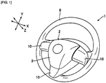
- FIGS. 1 and 2 are views schematically illustrating a steering wheel 1 of the steering wheel apparatus for a vehicle to which the damper mechanism of a steering wheel according to the invention is applied.
- FIG. 1 illustrates a perspective view of the entire steering wheel 1
- FIG. 2 illustrates a cross-sectional side view.
- directions are illustrated, on the assumption that a steering position of the steering wheel 1 attached to a vehicle is in a neutral position.
- a Z axis is set to have a downward side in a front wheel direction of a vehicle on a steering column (steering shaft) (not illustrated) and an upward side in a direction toward the steering wheel 1.
- an X axis is set from a 9-o'clock direction (left direction) toward a 3-o'clock direction (right direction), and a Y axis is set from a 6-o'clock direction (rear direction) toward a 12-o'clock direction (forward direction), with a position of 12 o'clock of an analog 12-hour clock as a front side of a vehicle.
- a side viewed from a side of a driver is referred to as a front side, and an opposite side thereof is referred to as a back side.
- the steering wheel 1 is installed at a driver seat of a vehicle to be connected to the steering shaft that penetrates an inside of the steering column (not illustrated) and transmit an operation force of a driver to a steering gear or the like.
- An airbag module 2 that functions as a front airbag in an emergency is attached at a center of the steering wheel 1. Although the description is omitted, the airbag module 2 also functions as a horn switch that a driver pushes when ringing a horn, in normal times.
- the airbag module 2 at a side of a driver is covered with a resin horn cover 3 which functions as a designed face.
- a tray-shaped housing 4 is provided at the back of the horn cover 3.
- An airbag cushion 5 that is unfolded to expand in an emergency is folded to be accommodated inside the horn cover 3.
- An inflator 6 provided to be accommodated in the airbag cushion 5 is attached to the housing 4.
- an inflator gas is supplied from the inflator 6 to the airbag cushion 5, and the airbag cushion 5 tears open the horn cover 3 to be unfolded to expand in a vehicle interior space and restrains a driver.
- a base part of the steering wheel 1 is configured of a metal cored bar member 7.
- the cored bar member 7 is largely configured to include a central boss region 8, a circular rim 9 that a driver grips, and a spoke 10 that connects the boss region 8 and the rim 9.
- the steering shaft is connected to the boss region 8.
- the airbag module 2 functions as a horn switch as described above and further as a module damper mechanism that attenuates vibration, as well as functioning as a front airbag. Configurational elements that realize the function as the horn switch and the module damper mechanism will be described below.
- the airbag module 2 is configured to include: a metal housing 4 that is formed into a tray shape, in which a peripheral wall 4b is formed around a bottom surface functioning as an inflator attaching surface 4a, and that has an inflator inserting hole 4c at a center of the housing and two damper units attaching through-holes 4d at both sides of the housing; two damper units 11 that are mounted in the through-holes 4d; a metal pin 12 that is inserted from the housing 4 toward the boss region 8 to be slidable in the damper unit 11; an inflator 6 that is provided to be inserted into the inflator inserting hole 4c from an opposite side (side of the cored bar member 7) of the peripheral wall 4b such that an outer peripheral flange 6a abuts the inflator attaching surface 4a of
- the pin 12 that projects from the bottom surface 4a of the housing 4 has a horn spring (coil spring) 17 which surrounds the pin.
- two metal coil springs 19 which are elastic-support members are provided on the bottom surface 4a of the housing 4 at an opposite side of the peripheral wall 4b, with a plate-shaped damper 18 interposed between the springs from both sides along an X-axis direction.
- the coil springs 19 are provided between the cored bar member 7 and the airbag module 2 (housing 4).
- damper units 11 are arranged in the housing 4.
- the damper unit 11 is a member that elastically attaches the housing 4 to the cored bar member 7 and is central to the module damper mechanism.
- the two damper units 11 are disposed at a center in an up-down direction of the airbag module 2 (housing 4) in the up-down direction (Y-axis direction), based on a neutral position of the steering wheel 1.
- the damper units 11 are disposed closer to both right and left sides in a right-left direction of the airbag module 2 (housing 4) in the right-left direction (X-axis direction), based on the neutral position of the steering wheel 1.
- the two damper units 11 are disposed at an equal distance from a central axis C in the right-left direction of the airbag module 2 (housing 4).
- the rod-shaped pin 12 projects from the damper unit 11 toward the boss region 8 of the cored bar member 7 in the Z-axis direction (refer to FIG. 2 ).
- the pin 12 is fixed to the cored bar member 7, and thereby the steering wheel 1 and the airbag module 2 are connected to each other.
- the damper units 11 that inhibit vibration of the steering wheel 1 are disposed between the airbag module 2 and the steering wheel 1.
- the pin 12 is inserted into the cored bar member 7 through a coil-shaped horn spring 17.
- the horn spring 17 is installed between the airbag module 2 and the cored bar member 7 to ensure a gap therebetween.
- the airbag module 2 released from a pressing operation (refer to an arrow B in FIG. 2 ) performed by a driver during a horn operation is separated from the cored bar member 7 to return to an original position.
- the damper unit 11 is configured to have an annular synthetic resin sleeve that covers and holds a ring-shaped elastic body for damping vibration, and the pin 12 of the damper unit 11 is slidably inserted into the elastic body.
- the sleeve is attached to the through-hole 4d formed in the housing 4 that configures the airbag module 2, and thereby the damper unit 11 is fixed to the airbag module 2.
- the airbag module 2 is provided with respect to the steering wheel 1 to be slidable toward the side of the steering wheel 1 via the pin 12 in a state in which the airbag module is elastically supported by the damper unit 11 having the elastic body.
- the vibration of the steering wheel 1 is transmitted to the damper unit 11 via the pin 12, and the transmitted vibration is attenuated in the damper unit 11 that uses the airbag module 2 as the damper mass.
- the horn spring 17 is elastically restored such that the airbag module 2 is retracted, and thereby the contact points are separated from each other such that ringing is to be stopped.
- the plate-shaped damper 18 as an engaging mechanism that holds the steering wheel 1 and the airbag module 2 in a relatively displaceable manner is provided in parallel with the damper unit 11, between the cored bar member 7 of the steering wheel 1 and the housing 4 of the airbag module 2.
- relative displacement means a change in separation distance between the steering wheel 1 and the airbag module 2 due to vibration of the steering wheel 1 and damping by the damper unit 11, and the engaging mechanism is configured to allow the change in distance.
- the plate-shaped damper 18 is disposed closer to a lower side of the steering wheel 1 in the up-down direction (Y-axis direction), based on the neutral position of the steering wheel 1. In a positional relationship with the damper units 11, the plate-shaped damper is disposed closer to a lower side (6-o'clock side) than the damper units 11 at a center of the two damper units 11.
- the damper units 11 and the plate-shaped damper 18 are provided to be disposed at the vertexes of an inverted isosceles triangle with respect to the airbag module 2.
- the two coil springs 19 described above are arranged at both right and left sides of the plate-shaped damper 18 along the X-axis direction.
- the plate-shaped damper 18 is configured to have a (metal or synthetic resin) leaf spring 20 as a principal member and an elastic piece 21 that is attached to the leaf spring.
- the plate-shaped damper 18 transmits vibration from the steering wheel 1 to the airbag module 2 by an elastic action of the plate-shaped damper and damps the vibration (mainly vibration in the Y-axis direction) of the steering wheel 1 by the elastic action due to plate bending in cooperation with the airbag module 2 functioning as the damper mass.
- the plate-shaped damper 18 may be made of metal such as steel or stainless steel or may be formed of a synthetic resin material by resin molding.
- the synthetic resin material include preferably nylon 66 or glass-compounded nylon 66, polypropylene (PP), and polyacetal (POM).
- the housing and the plate-shaped damper 18 can be integrally molded, and the sleeve, the housing 4, and the plate-shaped damper 18 can also be integrally molded.
- the plate-shaped damper 18 is configured to have a joining portion 18a at an upper end portion side thereof and a fitting portion at a lower end portion side thereof along an up-down length direction (Z-axis direction).
- the joining portion is joined to the housing 4 of the airbag module 2, and the fitting portion with respect to the steering wheel 1 has an elastic piece 21 to be described below in the first embodiment and has a holder 18b that is held to a support bar 22 formed on the cored bar member 7 of the steering wheel 1.
- the joining portion 18a of the plate-shaped damper 18 has a small hole 24 into which a rivet 23 is hammered, and a window portion 25 is formed between the joining portion 18a and the holder 18b.
- a crosspiece 26 below the window portion 25 has an insertion hole 27 into which the elastic piece 21 is pressed to be attached, and a recessed cutout portion 28 is formed below the crosspiece 26.
- the joining portion 18a comes into bump contact with the peripheral wall 4b of the housing 4 and is joined to the housing 4 with the rivet 23.
- the peripheral wall 4b of the housing 4 is formed to be upright from the bottom surface functioning as the inflator attaching surface 4a, and the joining portion 18a is joined to the housing 4 at a position closer to a side of the horn cover 3 than to the inflator attaching surface 4a in a location or the like in which the horn cover 3 is secured with the rivet 16.
- a pair of holders 18b is formed in a state of being extended toward a thickness direction of the leaf spring 20 from both edges in a width direction of a plate surface of the leaf spring 20 to one side.
- the holder 18b has a tapered edge portion from an upper end that is largely extended from the plate surface toward a lower end that is not extended in the thickness direction, along an up-down length direction of the leaf spring 20, the tapered edge portion functioning as a slide guide 29 and the largely extended upper end functioning as a hook 30.
- the holder 18b is formed by bending the plate-shaped damper 18 configured of the leaf spring 20 as a principal member and is formed to include the plate-shaped hook 30 as illustrated in the drawing.
- the plate-shaped damper 18 can restorably perform plate bending deformation by elasticity of the leaf spring 20, between the holder 18b and the joining portion 18a.
- the elastic piece 21 is formed of a rubber material such as ethylene propylene diene rubber (EPDM), silicone rubber, nitrile rubber (NBR), a synthetic resin material such as nylon 66, glass-compounded nylon 66, polypropylene (PP), polyacetal (POM), or the like.
- EPDM ethylene propylene diene rubber
- NBR nitrile rubber
- synthetic resin material such as nylon 66, glass-compounded nylon 66, polypropylene (PP), polyacetal (POM), or the like.
- the elastic piece 21 is configured to have a main body portion 21a which appears on a side of the holder 18b of the plate-shaped damper 18, an insertion portion 21b which protrudes from the main body portion 21a and is inserted into the insertion hole 27, and a lock portion 21c which protrudes from the insertion portion 21b and is locked to the crosspiece 26 at an opposite side of the main body portion 21a so as to fix the elastic piece 21 to the leaf spring 20, the main body portion, the insertion portion, and the lock portion being integrally molded.
- An upper end of the main body portion 21a has a collar 21d that covers a lower edge of the window portion 25.
- the lock portion 21c is pushed into the leaf spring 20 via the insertion hole 27 such that the insertion portion 21b is positioned in the insertion hole 27, and thereby the elastic piece 21 is attached to the leaf spring.
- the elastic piece 21 is disposed to be interposed between the pair of holders 18b.
- the main body portion 21a is attached to the leaf spring 20 such that a height position of the collar 21d is the same as or approximate to a height position of the hook 30.
- the plate-shaped damper 18 having the elastic piece 21 is held by the support bar 22 of the cored bar member 7 of the steering wheel 1.
- the support bar 22 is provided to intersect in a transverse orientation with respect to the up-down length direction of the leaf spring 20 in which the joining portion 18a and the holder 18b are formed.
- the support bar 22 projects more in the up-down length direction of the leaf spring 20 at a location corresponding to the elastic piece 21, compared to locations corresponding to the pair of holders 18b of the plate-shaped damper 18, and a projecting step portion 22a is formed.
- a positional relationship (dimensional relationship) between the support bar 22, the holder 18b of the plate-shaped damper 18, and the elastic piece 21 is described.
- the slide guide 29 comes into bump contact with the support bar 22 from above in the up-down length direction of the leaf spring 20, as illustrated in FIG. 8 .
- a thickness of the main body portion 21a of the elastic piece 21 in the thickness direction of the leaf spring 20 is set to a thickness dimension by which the main body portion does not come into contact with the step portion 22a.
- an upward projecting dimension of the step portion 22a is set to a dimension by which the step portion does not come into contact with the main body portion 21a.
- an extending dimension of the slide guide 29 is set to a dimension by which the slide guide does not come into contact with the step portion 22a and the main body portion 21a, when the slide guide comes into bump contact with the support bar 22.
- a thickness of the main body portion 21a of the elastic piece 21 in the thickness direction of the leaf spring 20 is set to a thickness dimension by which the main body portion comes into contact with the step portion 22a from below, and a gap is formed between the leaf spring 20 and the support bar 22.
- a downward projecting dimension of the step portion 22a is set to a dimension by which the gap D is formed between the hook 30 and the support bar 22, when the collar 21d is in contact with the step portion 22a.
- a dimension of the plate-shaped damper 18 is set such that only the elastic piece 21 at the side of the airbag module 2 can come into elastic contact with the support bar 22 at the side of the steering wheel 1.
- the plate-shaped damper 18 includes the hook 30, thereby, being able to be reliably held by the steering wheel 1.
- FIG. 10 illustrates an attachment operation of the plate-shaped damper
- FIG. 11 illustrates a detachment operation.
- the plate-shaped damper 18 has the engaging mechanism, that is, the engaging mechanism as a specific example, which is provided in parallel with the damper unit 11, between the steering wheel 1 and an airbag module 2 and holds the steering wheel 1 and the airbag module 2 in a relatively displaceable manner. In this manner, the engaging mechanism can stably hold the airbag module 2 with respect to the steering wheel 1, and it is possible to cause the damper unit 11 to appropriately and sufficiently exhibit its performance to ensure a high damping effect of the vibration of the steering wheel 1.
- the engaging mechanism that is, the engaging mechanism as a specific example, which is provided in parallel with the damper unit 11, between the steering wheel 1 and an airbag module 2 and holds the steering wheel 1 and the airbag module 2 in a relatively displaceable manner. In this manner, the engaging mechanism can stably hold the airbag module 2 with respect to the steering wheel 1, and it is possible to cause the damper unit 11 to appropriately and sufficiently exhibit its performance to ensure a high damping effect of the vibration of the steering wheel 1.
- the engaging mechanism has the hook 30 formed into a plate shape, and the hook 30 holds the steering wheel 1 and the airbag module 2 in a relatively displaceable manner. Hence, it is possible to configure the engaging mechanism with high productivity and a good attachment property. It is needless to say that as the engaging mechanism, instead of the hook 30, a known tab member having flexibility which is used to attach a curtain airbag to a roof-side rail may be used by being hung or the like on the support bar 22 of the steering wheel 1.
- the plate-shaped damper 18 has a plate shape literally, the plate-shaped damper is compact, and instead of one damper unit 11, for example, the plate-shaped damper is disposed in parallel with the other damper unit 11. In this manner, it is possible to decrease the airbag module 2 in size.
- the plate-shaped damper 18 connects the steering wheel 1 and the airbag module 2 to each other, and thus the vibration of the steering wheel 1 can be attenuated by the plate-shaped damper 18 that uses the airbag module 2 as the damper mass. Hence, it is possible to ensure the damping effect comparable to that of the known art with the other damper unit 11.
- the plate-shaped damper 18 is configured to have the leaf spring 20 and can damp the vibration (mainly vibration in the Y-axis direction) of the steering wheel 1 by the elastic operation due to plate bending which is promoted by the leaf spring 20.
- Elasticity of the leaf spring 20 is adjusted, and thereby it is possible to adjust an attenuating vibration frequency.
- the leaf spring 20 is elastically bent and deformed, and thereby it is possible to perform attachment of the plate-shaped damper 18 to the steering wheel 1.
- the plate-shaped damper 18 is disposed closer to a lower side (6-o'clock side in the Y-axis direction) of the airbag module 2 in the up-down direction, and thus it is possible to decrease a dimension of the airbag module 2 in the up-down direction.
- the plate-shaped damper 18 has the rubber or synthetic resin elastic piece 21 that can come into elastic contact with the support bar 22 of the steering wheel 1 and transmits the vibration of the steering wheel 1 to the side of the airbag module 2 via the elastic piece 21. Hence, it is possible to adjust the attenuating vibration frequency by hardness of the elastic piece 21 and a period of contact of the elastic piece 21 with the support bar 22.
- the gap D is to be formed between the hook 30 of the holder 18b and the support bar 22. Hence, it is possible to prevent abnormal noise from occurring due to the vibration of the steering wheel 1.
- a joining position of the joining portion 18a of the plate-shaped damper 18 to the housing 4 is set to a position closer to the horn cover 3 than to the inflator attaching surface 4a, and thus a joining operation is simple. In addition, it is possible to match occurrence positions of attenuating operations by the damper unit 11 and the plate-shaped damper 18.
- the coil springs 19 are provided in parallel with the plate-shaped damper 18, and thus it is possible to stably support a connection location of the steering wheel 1 to the airbag module 2 and a periphery of the connection location by the plate-shaped damper 18.
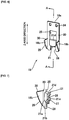
- FIGS. 12 and 13 illustrate modification examples of an attachment structure of the plate-shaped damper 18 to the housing 4.
- the joining portion 18a of the plate-shaped damper 18 is to be joined to the peripheral wall 4b of the housing 4 by spot welding 31.
- FIG. 13(A) is a perspective view depicting a state before the plate-shaped damper 18 is attached
- FIG. 13(B) is a cross-sectional side view illustrating an attachment operation.
- the housing 4 has a window hole 32 formed to have a wide portion 32a and a narrow portion 32b in a series up and down in a height direction of the peripheral wall 4b.
- the housing 4 has a penetrating hole 33 that the leaf spring 20 with the elastic piece 21 attached penetrates, the penetrating hole being formed corresponding to a position of the window hole 32, in the inflator attaching surface 4a of the bottom surface.
- the holder 18b is not provided.
- the joining portion 18a of the plate-shaped damper 18 has an overhang portion 34 that is to straddle the peripheral wall 4b of the housing 4 at an upper end, and a downward clip portion 35 is formed to be continuous to the overhang portion 34.
- the clip portion 35 is formed to have a narrow inserting portion 35a and a wide protruding portion 35b.
- the leaf spring 20 penetrates the penetrating hole 33, the clip portion 35 penetrates the peripheral wall 4b from an outer side toward an inner side of the peripheral wall 4b via the window hole 32 such that the inserting portion 35a penetrates the narrow portion 32b and the protruding portion 35b penetrates the wide portion 32a.
- the clip portion 35 pinches the peripheral wall 4b from the inner and outer sides, and thereby the joining portion 18a is to be joined to the housing 4.
- FIGS. 14 and 15 illustrate a second embodiment of the damper mechanism of a steering wheel and the steering wheel apparatus for a vehicle according to the invention.
- the airbag module 2 has a configuration in which the metal housing 4 has the metal or synthetic resin plate-shaped damper 18.
- a housing 4 and a plate-shaped damper 18 are made of a synthetic resin.
- the plate-shaped damper 18 is integrally formed to the housing 4 by resin molding. Specifically, the plate-shaped damper 18 is integrated to the housing 4 at the location of a joining portion 18a. Consequently, it is possible to achieve a reduction in the number of parts and in cost.
- Damper units 11 are held to the housing 4 as described above.
- a synthetic resin sleeve 11a of the damper unit 11 is integrally formed to the housing 4 by resin molding. Consequently, it is possible to achieve a more reduction in the number of parts and in cost.
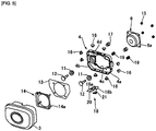
- FIG. 15 illustrates a structure of an airbag module 2 included in the second embodiment.
- the airbag module 2 is configured to include: a synthetic resin housing 4 that has an inflator inserting hole 4c at a center thereof and two sleeves 11a at both sides thereof, the two sleeves being integrally molded to the housing; two damper units 11 configured to have an elastic body 11b which is mounted in the sleeve 11a; a metal pin 12 that is inserted from the housing 4 toward a boss region 8 to be slidable in the damper unit 11; an inflator 6 that is provided to be inserted into the inflator inserting hole 4c from a side of the cored bar member 7 such that an outer peripheral flange 6a abuts an inflator attaching surface 4a of the housing 4; a metal or synthetic resin attachment plate 13 that has a plurality of slits 13a, with which a horn cover 3 engages, in an outer peripheral edge, is installed to adjoin the inflator attaching surface 4a, and accommodates the housing
- FIG. 16 illustrates a third embodiment of the damper mechanism of a steering wheel and the steering wheel apparatus for a vehicle according to the invention.
- a housing 4 that holds a damper unit 11 is made of metal, and a plate-shaped damper 18 is integrally formed to the housing 4 by overmold-resin molding.
- the plate-shaped damper 18 and the housing 4 are integrally formed, and thereby it is possible to achieve a reduction in the number of parts and in cost, similar to the second embodiment.
- the third embodiment can be configured in the same assembly as that of the second embodiment illustrated in FIG. 15 .
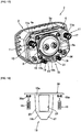
- FIGS. 17 and 18 illustrate a fourth embodiment of the damper mechanism of a steering wheel and the steering wheel apparatus for a vehicle according to the invention.
- the fourth embodiment represents a case where a housing 4 that is assembled at a side of an airbag module 2 is made of metal having the conductivity, a pin 12 that is provided at a side of the steering wheel 1 is also made of metal having the conductivity, and the housing 4 and the pin 12 function as horn contact points which come into contact with and are separated from each other.
- a horn cover 3 of the airbag module 2 which receives a bias force of a horn spring 17 is pressed toward a cored bar member 7, and thereby the housing 4 comes into contact with the pin 12. Consequently, a horn rings.
- a plate-shaped damper 18 that is attached to the housing 4 is formed of an insulating synthetic resin material.
- a metal elastic-support member 19 is to be provided in parallel with the plate-shaped damper 18, between the housing 4 and the cored bar member 7.
- the fourth embodiment has a configuration in which the elastic-support member 19 is installed by using the plate-shaped damper 18 made of the insulating synthetic resin material.
- the joining portion 18a described above of the plate-shaped damper 18 has an insulating sheet portion 36 that is integrally formed thereto and is expanded to both sides in the X-axis direction.
- a pair of protrusions 36a is formed at both end sides of the insulating sheet portion 36.
- Two elastic-support members 19 have one end that is fitted to each of the protrusions 36a and are provided to the housing 4 via the insulating sheet portion 36. Consequently, conduction by the elastic-support member 19 is cut off such that it is possible to ensure the horn function.
- the plate-shaped damper 18 is configured of a member separated from the housing 4, unlike the second and third embodiments.
- Attachment of the plate-shaped damper 18 is performed as follows. First, the insulating sheet portion 36 of the plate-shaped damper 18 adjoins the housing 4 to be temporarily fixed to an attachment plate 13, between the housing 4 at a side of an inflator 6 and the attachment plate 13 at the side of the horn cover 3.
- the joining portion 18a of the plate-shaped damper 18 including the insulating sheet portion 36 is sandwiched between the attachment plate 13 and the housing 4 in an operation of attaching the attachment plate 13 to the housing 4 (an operation of fastening the inflator 6 to a retainer ring 14), and thereby the plate-shaped damper 18 is to be fixed to the side of the housing 4.
- the fourth embodiment even in a case of using the housing 4 as the horn contact point, it is possible to assemble the plate-shaped damper 18 and the elastic-support member 19 with a reasonably small number of parts, at low costs, and through an easy operation.
- FIG. 19 illustrates a modification example of disposition of the pin 12 and the plate-shaped damper 18, which is applicable to the embodiments described above.
- the modification example has a configuration in which it is possible to improve an attachment property of an airbag module 2 to a cored bar member 7, the airbag module being provided to have the pin 12 and the plate-shaped damper 18 assembled thereto.
- a damper unit 11 that is installed at a side of the airbag module 2 has the pin 12 which is to be inserted into and attached to a boss region 8 of the steering wheel 1.
- the pin 12 projects more than a fitting portion 18b so as to be attached to the cored bar member 7 before the fitting portion 18b.
- a configuration in which attachment of the pin 12 to the cored bar member 7 is completed in advance is employed.
- an elastic piece 21 of the plate-shaped damper 18 engages with the side of the steering wheel 1, for example, the support bar 22, it is possible to inhibit positions of the pin 12 in a 3-o'clock direction and a 9-o'clock direction from shifting by an operation reaction force of engaging thereof, and it is possible to enhance accuracy of an attachment position of the damper unit 11.
- the damper units 11 are disposed at the center in the up-down direction (Y-axis direction) of the housing 4 of the airbag module 2, based on the neutral position of the steering wheel 1, and thus it is possible to easily adjust the attenuating vibration frequency.
- the damper units may be disposed closer to an upper end side from the center in the up-down direction (Y-axis direction) of the housing 4 of the airbag module 2, based on the neutral position of the steering wheel 1 (the drawing illustrating a shift of a position of a through-hole 4d with respect to a distance G from the center to an upper end of the housing 4 in the up-down direction).
- FIG. 21 illustrates an example of the attachment structure of the horn cover 3 to the attachment plate 13.
- the attachment plate 13 has a slit 13a into which a locking hook piece 3a of the horn cover 3 is inserted in a freely oscillating manner.
- the inflator 6 is fastened to the retainer ring 14 with the nut 15, and thereby the attachment plate 13 overlaps the inflator attaching surface 4a of the housing 4.
- the housing 4 and the attachment plate 13 overlap each other, a peripheral edge of the housing 4 is partially covered with the slit 13a.
- damper units 11 are provided at the side of the airbag module 2 (in the through-holes 4d of the housing 4); however, the damper units may be provided at the side of the steering wheel 1.
- the joining portion 18a of the plate-shaped damper 18 is joined to the side of the airbag module 2, and the holder 18b is held at the side of the steering wheel 1 is described; however, the joining portion 18a may be joined to the side of the steering wheel 1, and the holder 18b may be held at the side of the airbag module 2.
- the plate-shaped damper 18 includes the leaf spring 20 which has the joining portion 18a that is joined to the steering wheel 1 and the fitting portion 18b with respect to the airbag module 2, and the leaf spring 20 is elastically bendable and deformable between the fitting portion 18b and the joining portion 18a.
- the damper unit 11 is installed on the steering wheel 1 and has the pin 12 which is to be attached to the airbag module 2, and the pin 12 projects more than the fitting portion 18b to be attached to the airbag module before the fitting portion 18b.
- the plate-shaped damper 18 has the elastic piece 21 which can come into elastic contact with the airbag module 2, a configuration in which the fitting portion has the holder 18b that holds the plate-shaped damper 18 to the airbag module 2, or a configuration in which, when the elastic piece 21 comes into contact with the airbag module 2, the gap D is formed between the holder 18b and the airbag module 2.
- damper mechanism of a steering wheel and the steering wheel apparatus for a vehicle described above are the preferred examples of the invention, and embodiments other than those can also be implemented or fulfilled in various types of methods.
- the invention is not restricted to a shape, a size, configurational disposition, and the like of parts illustrated in detail in the accompanying drawings.
- expressions and terms used in the specification of the application are used for providing the description, and thus the invention is not limited thereto, unless particularly described otherwise.
- the invention is defined by the appended claims.
Claims (27)
- Dämpfermechanismus eines Lenkrads (1), der Folgendes umfasst:eine oder zwei Dämpfereinheiten (11), die zwischen dem Lenkrad (1) und einem Airbagmodul (2) bereitgestellt sind, die als eine Dämpfermasse wirken und Schwingungen des Lenkrads (1) dämpfen; undeinen Eingriffsmechanismus, der parallel zu der Dämpfereinheit (11) zwischen dem Lenkrad (1) und dem Airbagmodul (2) bereitgestellt ist und das Lenkrad (1) und das Airbagmodul (2) in einer relativ verschiebbaren Weise hältdadurch gekennzeichnet, dass
der Eingriffsmechanismus einen plattenförmigen Dämpfer (18) konfiguriert, der Schwingungen des Lenkrads (1) dämpft. - Dämpfermechanismus eines Lenkrads (1) nach Anspruch 1,
wobei der Eingriffsmechanismus einen Hakenabschnitt aufweist. - Dämpfermechanismus eines Lenkrads (1) nach Anspruch 1 oder 2,
wobei der plattenförmige Dämpfer (18) aus einem Kunstharzmaterial durch Harzformen ausgebildet ist. - Dämpfermechanismus eines Lenkrads (1) nach einem der Ansprüche 1 bis 3,wobei das Airbagmodul (2) ein Kunstharzgehäuse (4) beinhaltet, das die Dämpfereinheit (11) hält, undwobei der plattenförmige Dämpfer (18) mit dem Gehäuse (4) durch Harzformen einstückig ausgebildet ist.
- Dämpfermechanismus eines Lenkrads (1) nach einem der Ansprüche 1 bis 4,
wobei die Dämpfereinheit (11) eine Hülse (11a) aufweist, die einen elastischen Körper (11b) hält, und die Hülse (11a) mit dem Kunstharzgehäuse (4) und dem plattenförmigen Dämpfer (18) einstückig ausgebildet ist. - Dämpfermechanismus eines Lenkrads (1) nach Anspruch 1 oder 3,wobei das Airbagmodul (2) ein Metallgehäuse (4) beinhaltet, das die Dämpfereinheit (11) hält, undwobei der plattenförmige Dämpfer (18) mit dem Gehäuse (4) durch Umspritzformen mit Harz einstückig ausgebildet ist.
- Dämpfermechanismus eines Lenkrads (1) nach Anspruch 1 oder 3,wobei das Airbagmodul (2) ein Metallgehäuse (4) beinhaltet, das die Dämpfereinheit (11) hält und einen Hupenberührungspunkt konfiguriert, der mit einem Hupenberührungspunkt an einer Seite des Lenkrads (1) in Berührung kommt und von diesem getrennt ist, undwobei der plattenförmige Dämpfer (18) aus einem isolierenden Kunstharzmaterial ausgebildet und an dem Gehäuse (4) befestigt ist.
- Dämpfermechanismus eines Lenkrads (1) nach Anspruch 6 oder 7,
wobei die Dämpfereinheit (11) eine Hülse (11a) aufweist, die einen elastischen Körper (11b) hält, und die Hülse (11a) mit dem Gehäuse (4) einstückig ausgebildet ist. - Dämpfermechanismus eines Lenkrads (1) nach einem der Ansprüche 1 bis 8,wobei der plattenförmige Dämpfer (18) eine Blattfeder (20) beinhaltet, die einen Verbindungsabschnitt (18a), der mit dem Airbagmodul (2) verbunden ist, und einen Passabschnitt in Bezug auf das Lenkrad (1) aufweist, undwobei die Blattfeder (20) zwischen dem Passabschnitt und dem Verbindungsabschnitt (18a) elastisch biegbar und verformbar ist.
- Dämpfermechanismus eines Lenkrads nach Anspruch 9,wobei die Dämpfereinheit (11) an dem Airbagmodul (2) installiert ist und einen Stift (12) aufweist, der an dem Lenkrad (1) zu befestigen ist, undwobei der Stift (12) mehr hervorsteht als der Passabschnitt, um an dem Lenkrad (1) vor dem Passabschnitt befestigt zu werden.
- Dämpfermechanismus eines Lenkrads (1) nach Anspruch 9 oder 10,
wobei der Passabschnitt ein elastisches Teil (21) aufweist, das konfiguriert ist, um mit dem Lenkrad (1) in elastische Berührung zu kommen. - Dämpfermechanismus eines Lenkrads (1) nach einem der Ansprüche 9 bis 11,
wobei der Passabschnitt einen Halter (18b) aufweist, der den plattenförmigen Dämpfer (18) an dem Lenkrad (1) hält. - Dämpfermechanismus eines Lenkrads (1) nach Anspruch 12,
wobei, wenn das elastische Teil (21) mit dem Lenkrad (1) in Berührung steht, ein Spalt (D) zwischen dem Halter (18b) und dem Lenkrad (1) ausgebildet wird. - Dämpfermechanismus eines Lenkrads nach einem der Ansprüche 9 bis 13,wobei das Airbagmodul (2) einen Gasgenerator (6) beinhaltet, wobei das Gehäuse (4) eine Gasgeneratorbefestigungsoberfläche und eine Hupenabdeckung (3) aufweist, die den Gasgenerator (6) von einer gegenüberliegenden Seite der Gasgeneratorbefestigungsoberfläche abdeckt, undwobei der Verbindungsabschnitt (18a) des plattenförmigen Dämpfers (18) mit dem Gehäuse (4) an einer Position verbunden ist, die näher an der Hupenabdeckung (3) als an der Gasgeneratorbefestigungsoberfläche liegt.
- Dämpfermechanismus eines Lenkrads (1) nach einem der Ansprüche 1 bis 8,wobei der plattenförmige Dämpfer (18) eine Blattfeder (20) beinhaltet, die einen Verbindungsabschnitt (18a), der mit dem Lenkrad (1) verbunden ist, und einen Passabschnitt in Bezug auf das Airbagmodul (2) aufweist, undwobei die Blattfeder (20) zwischen dem Passabschnitt und dem Verbindungsabschnitt (18a) elastisch biegbar und verformbar ist.
- Dämpfermechanismus eines Lenkrads (1) nach Anspruch 15,wobei die Dämpfereinheit (11) an dem Lenkrad (1) installiert ist und einen Stift (12) aufweist, der an dem Airbagmodul (2) zu befestigen ist, undwobei der Stift (12) mehr hervorsteht als der Passabschnitt, um an dem Airbagmodul (2) vor dem Passabschnitt befestigt zu werden.
- Dämpfermechanismus eines Lenkrads (1) nach Anspruch 15 oder 16,
wobei der Passabschnitt ein elastisches Teil (21) aufweist, das konfiguriert ist, um mit dem Airbagmodul (2) in elastische Berührung zu kommen. - Dämpfermechanismus eines Lenkrads (1) nach einem der Ansprüche 15 bis 17,
wobei der Passabschnitt einen Halter (18b) aufweist, der den plattenförmigen Dämpfer (189) an dem Airbagmodul (2) hält. - Dämpfermechanismus eines Lenkrads (1) nach Anspruch 18,
wobei, wenn das elastische Teil (21) mit dem Airbagmodul (2) in Berührung steht, ein Spalt (D) zwischen dem Halter (18b) und dem Airbagmodul (2) ausgebildet wird. - Dämpfermechanismus eines Lenkrads (1) nach einem der Ansprüche 1 bis 19, der ferner Folgendes umfasst:
ein elastisches Stützelement, das parallel zu dem plattenförmigen Dämpfer (18) zwischen dem Lenkrad (1) und dem Airbagmodul (2) bereitgestellt ist. - Dämpfermechanismus eines Lenkrads (1) nach einem der Ansprüche 7 bis 19,
wobei der plattenförmige Dämpfer (18) einen einstückig ausgebildeten isolierenden Folienabschnitt (36) beinhaltet und das Gehäuse (4) ein metallisches elastisches Stützelement beinhaltet, das parallel zu dem plattenförmigen Dämpfer (18) zwischen den Lenkrad (1) und dem Airbagmodul (2) bereitgestellt ist, wobei das metallische elastische Stützelement über den isolierenden Folienabschnitt (36) an dem Gehäuse (2) bereitgestellt ist. - Dämpfermechanismus eines Lenkrads (1) nach Anspruch 21,wobei das Airbagmodul (2) eine Befestigungsplatte (13) beinhaltet, an der das Gehäuse (4), an dem ein Gasgenerator (6) befestigt und fixiert ist, und eine Hupenabdeckung (3), die den Gasgenerator (6) abdeckt, befestigt und fixiert sind, undwobei der isolierende Folienabschnitt (36) vorübergehend an der Befestigungsplatte (13) durch Angrenzen des Gehäuses (4) fixiert wird und durch Befestigung der Befestigungsplatte (13) und des Gehäuses (4) fixiert wird.
- Dämpfermechanismus eines Lenkrads (1) nach einem der Ansprüche 1 bis 22,
wobei die Dämpfereinheit (11) in einer Mitte des Airbagmoduls (2) in einer Oben-Unten-Richtung, basierend auf einer neutralen Position des Lenkrads (1), angeordnet ist. - Dämpfermechanismus eines Lenkrads (1) nach einem der Ansprüche 1 bis 22,
wobei die Dämpfereinheit (11) näher an einer oberen Endseite von einer Mitte des Airbagmoduls (2) in einer Oben-Unten-Richtung, basierend auf einer neutralen Position des Lenkrads (1), angeordnet ist. - Dämpfermechanismus eines Lenkrads (1) nach einem der Ansprüche 1 bis 24,
wobei, wenn die zwei Dämpfereinheiten (11) bereitgestellt sind, die zwei Dämpfereinheiten (11) näher an beiden Seiten des Airbagmoduls (2) in einer Rechts-Links-Richtung, basierend auf einer neutralen Position des Lenkrads (1), angeordnet sind. - Dämpfermechanismus eines Lenkrads (1) nach einem der Ansprüche 1 bis 25,
wobei der plattenförmige Dämpfer (18) näher an einer unteren Seite des Lenkrads (1) in einer Oben-Unten-Richtung, basierend auf einer neutralen Position des Lenkrads (1), angeordnet ist. - Lenkradvorrichtung für ein Fahrzeug, die Folgendes umfasst:
den Dämpfermechanismus eines Lenkrads nach einem der Ansprüche 1 bis 26.
Applications Claiming Priority (3)
| Application Number | Priority Date | Filing Date | Title |
|---|---|---|---|
| JP2018131806 | 2018-07-11 | ||
| JP2018150732 | 2018-08-09 | ||
| JP2019087698A JP6905548B2 (ja) | 2018-07-11 | 2019-05-07 | ステアリングホイールのダンパ機構及び車両用ステアリングホイール装置 |
Publications (2)
| Publication Number | Publication Date |
|---|---|
| EP3594087A1 EP3594087A1 (de) | 2020-01-15 |
| EP3594087B1 true EP3594087B1 (de) | 2022-01-05 |
Family
ID=67437681
Family Applications (1)
| Application Number | Title | Priority Date | Filing Date |
|---|---|---|---|
| EP19185890.1A Active EP3594087B1 (de) | 2018-07-11 | 2019-07-11 | Dämpfermechanismus eines lenkrads und lenkradvorrichtung für fahrzeug |
Country Status (4)
| Country | Link |
|---|---|
| US (1) | US11267424B2 (de) |
| EP (1) | EP3594087B1 (de) |
| KR (1) | KR102249420B1 (de) |
| CN (1) | CN110712674B (de) |
Families Citing this family (10)
| Publication number | Priority date | Publication date | Assignee | Title |
|---|---|---|---|---|
| US11060428B2 (en) * | 2018-05-24 | 2021-07-13 | Tenneco Automotive Operating Company Inc. | Exhaust valve damper |
| CN113365899B (zh) * | 2019-02-08 | 2023-02-28 | 奥托立夫开发公司 | 车辆用方向盘的减振结构 |
| KR102654832B1 (ko) * | 2019-02-08 | 2024-04-05 | 아우토리브 디벨롭먼트 아베 | 차량용 스티어링 휠의 진동 감쇠 구조 및 차량용 스티어링 휠 장치 |
| KR102300454B1 (ko) | 2020-04-07 | 2021-09-09 | 아우토리브 디벨롭먼트 아베 | 자동차의 스티어링 휠 장치 |
| KR102493781B1 (ko) | 2021-01-11 | 2023-02-06 | 아우토리브 디벨롭먼트 아베 | 자동차의 스티어링 휠 장치 |
| KR102601024B1 (ko) | 2021-08-25 | 2023-11-13 | 아우토리브 디벨롭먼트 아베 | 자동차의 스티어링 휠 장치 |
| KR102613408B1 (ko) | 2021-09-09 | 2023-12-14 | 아우토리브 디벨롭먼트 아베 | 자동차의 스티어링 휠 장치 |
| DE102022122056B3 (de) | 2022-08-31 | 2024-02-01 | Autoliv Development Ab | Lenkrad mit einem Airbagmodul |
| DE102022122055A1 (de) | 2022-08-31 | 2024-02-29 | Autoliv Development Ab | Lenkrad mit einem Airbagmodul |
| DE102022122054A1 (de) | 2022-08-31 | 2024-02-29 | Autoliv Development Ab | Lenkrad mit einem Airbagmodul |
Family Cites Families (52)
| Publication number | Priority date | Publication date | Assignee | Title |
|---|---|---|---|---|
| FR1063327A (fr) * | 1952-08-25 | 1954-05-03 | Dispositif de protection contre les accidents occasionnés par les volants et arbres de direction et les pare-brise de véhicules automobiles | |
| US5239147A (en) * | 1992-08-03 | 1993-08-24 | Morton International, Inc. | Floating, serviceable horn switch, air bag modules |
| US5410114A (en) * | 1992-12-25 | 1995-04-25 | Toyoda Gosei Co., Ltd. | Steering wheel horn switch mechanism |
| US5350190A (en) * | 1993-07-06 | 1994-09-27 | Primrose, Inc. | Air bag assembly mount including snap-fit horn attachment |
| DE19541180A1 (de) * | 1995-11-04 | 1997-05-07 | Mst Automotive Gmbh | Mittel zur Befestigung eines Airbag-Moduls |
| US5947509A (en) * | 1996-09-24 | 1999-09-07 | Autoliv Asp, Inc. | Airbag inflator with snap-on mounting attachment |
| US5762359A (en) * | 1996-10-02 | 1998-06-09 | General Motors Corporation | Air bag module and steering wheel assembly |
| DE19724029A1 (de) * | 1997-06-06 | 1998-12-24 | Takata Europ Gmbh | Airbag-Vorrichtung |
| DE29805210U1 (de) * | 1998-03-23 | 1998-06-04 | Trw Automotive Safety Sys Gmbh | Aufprall-Schutzvorrichtung |
| US6082758A (en) * | 1998-08-17 | 2000-07-04 | General Motors Corporation | Driver air bag horn ground spring |
| DE19858691B4 (de) * | 1998-12-18 | 2010-01-07 | Delphi Automotive Systems Deutschland Gmbh | Luftsackmodul für Kraftfahrzeuge |
| DE20103891U1 (de) * | 2001-03-06 | 2002-04-11 | Trw Automotive Safety Sys Gmbh | Fahrzeuglenkrad |
| GB2383301A (en) * | 2001-12-18 | 2003-06-25 | Autoliv Dev | Air bag unit with locating means |
| JP3856390B2 (ja) * | 2003-06-23 | 2006-12-13 | 本田技研工業株式会社 | ステアリングホイール |
| KR100519231B1 (ko) * | 2003-08-14 | 2005-10-06 | 현대모비스 주식회사 | 차량의 혼 스위치 어셈블리 |
| KR100629340B1 (ko) * | 2005-01-21 | 2006-09-29 | 현대모비스 주식회사 | 혼 스위치 겸용 에어백장치 |
| US7621560B2 (en) * | 2005-02-07 | 2009-11-24 | Key Safety Systems, Inc | Horn switch |
| US7464959B2 (en) * | 2005-03-01 | 2008-12-16 | Trw Vehicle Safety Systems Inc. | Apparatus having a mechanism for limiting the movement of an air bag module relative to a steering wheel |
| WO2007013635A1 (ja) * | 2005-07-28 | 2007-02-01 | Autoliv Development Ab | エアバッグ装置 |
| DE102008039936A1 (de) * | 2008-08-27 | 2010-03-04 | Anvis Deutschland Gmbh | Elastische Aufhängung zum zumindest teilweisen Tilgen oder Löschen von Erregerschwingungen an einem Karosserieteil, Schwingungstilgungsanordnung und Verfahren zum Herstellen der elastischen Aufhängung |
| JP5005019B2 (ja) * | 2009-11-23 | 2012-08-22 | 本田技研工業株式会社 | ステアリングホイール |
| JP5497485B2 (ja) * | 2010-03-04 | 2014-05-21 | 芦森工業株式会社 | エアバッグ装置 |
| JP5432011B2 (ja) * | 2010-03-12 | 2014-03-05 | 芦森工業株式会社 | エアバッグ装置の取付部構造 |
| US8985623B2 (en) * | 2010-09-09 | 2015-03-24 | Autoliv Development Ab | Steering wheel structure with airbag module |
| EP2641811B1 (de) * | 2010-11-19 | 2015-09-30 | Honda Motor Co., Ltd. | Lenkrad |
| JP5836685B2 (ja) * | 2011-07-27 | 2015-12-24 | タカタ株式会社 | ステアリングホイール |
| JP2013071626A (ja) * | 2011-09-28 | 2013-04-22 | Toyoda Gosei Co Ltd | ステアリングホイールの制振構造 |
| KR101560541B1 (ko) * | 2012-04-13 | 2015-10-19 | 아우토리브 디벨롭먼트 아베 | 에어백 모듈과 스티어링 휠의 조립체 |
| JP5989449B2 (ja) * | 2012-08-06 | 2016-09-07 | タカタ株式会社 | ステアリングホイール |
| JP6185798B2 (ja) * | 2013-05-07 | 2017-08-23 | 日本プラスト株式会社 | ステアリングホイール |
| JP5971213B2 (ja) * | 2013-08-12 | 2016-08-17 | 豊田合成株式会社 | ステアリングホイール |
| JP2015071402A (ja) | 2013-09-04 | 2015-04-16 | オートリブ ディベロップメント エービー | ステアリングホイール装置 |
| CN103640618B (zh) * | 2013-11-28 | 2016-05-18 | 苏州先锋物流装备科技有限公司 | 一种方向盘阻尼系统 |
| WO2015098224A1 (ja) * | 2013-12-27 | 2015-07-02 | 本田技研工業株式会社 | ステアリングホイール構造 |
| GB2540254B (en) * | 2014-03-18 | 2018-02-28 | Nihon Plast Co Ltd | Steering wheel |
| WO2016002507A1 (ja) * | 2014-06-30 | 2016-01-07 | オートリブ ディベロップメント エービー | ステアリングホイールの振動低減構造 |
| JP6637665B2 (ja) * | 2014-09-24 | 2020-01-29 | Joyson Safety Systems Japan株式会社 | ステアリングホイール |
| KR102293578B1 (ko) * | 2015-07-22 | 2021-08-25 | 현대모비스 주식회사 | 조향휠 에어백 장치 |
| KR102487881B1 (ko) | 2015-11-09 | 2023-01-12 | 현대모비스 주식회사 | 차량용 에어백 모듈 |
| JP6624732B2 (ja) * | 2016-03-29 | 2019-12-25 | 日本プラスト株式会社 | ハンドル |
| JP2017178094A (ja) | 2016-03-30 | 2017-10-05 | 豊田合成株式会社 | エアバッグ装置の支持構造 |
| KR101807662B1 (ko) * | 2016-04-04 | 2018-01-18 | 아우토리브 디벨롭먼트 아베 | 자동차용 스티어링 휠의 혼 스위치 장치 |
| JP6823386B2 (ja) * | 2016-06-08 | 2021-02-03 | 本田技研工業株式会社 | ハンドル |
| US10150441B2 (en) * | 2016-10-21 | 2018-12-11 | Autoliv Asp, Inc. | Dampening driver airbag assemblies and related systems and methods |
| DE102016124530A1 (de) * | 2016-12-15 | 2018-06-21 | Trw Automotive Safety Systems Gmbh | Kopplungsvorrichtung zur schwingfähigen Befestigung eines Gassackmoduls an einem Fahrzeuglenkrad |
| EP3741647B1 (de) * | 2018-01-19 | 2022-11-09 | Autoliv Development AB | Lenkrad |
| JP7015194B2 (ja) * | 2018-03-19 | 2022-02-02 | 芦森工業株式会社 | ステアリングホイール |
| JP7094763B2 (ja) * | 2018-04-26 | 2022-07-04 | Joyson Safety Systems Japan株式会社 | ステアリングホイール |
| JP6968279B2 (ja) * | 2018-06-25 | 2021-11-17 | オートリブ ディベロップメント エービー | ステアリングホイールにおけるダンパユニットの取付固定構造及びステアリングホイール |
| JP7209953B2 (ja) * | 2018-08-01 | 2023-01-23 | 豊田合成株式会社 | ステアリングホイール |
| DE102018127637A1 (de) * | 2018-11-06 | 2020-05-07 | Trw Automotive Safety Systems Gmbh | Gassackmodul, verfahren zu dessen montage sowie lenkungsbaugruppe mit einem solchen gassackmodul |
| KR102593661B1 (ko) * | 2018-11-13 | 2023-10-25 | 현대모비스 주식회사 | 운전석용 에어백 장치 |
-
2019
- 2019-07-11 KR KR1020190084104A patent/KR102249420B1/ko active IP Right Grant
- 2019-07-11 CN CN201910625972.2A patent/CN110712674B/zh active Active
- 2019-07-11 US US16/508,864 patent/US11267424B2/en active Active
- 2019-07-11 EP EP19185890.1A patent/EP3594087B1/de active Active
Also Published As
| Publication number | Publication date |
|---|---|
| US20200017057A1 (en) | 2020-01-16 |
| CN110712674B (zh) | 2022-01-25 |
| KR20200006954A (ko) | 2020-01-21 |
| CN110712674A (zh) | 2020-01-21 |
| EP3594087A1 (de) | 2020-01-15 |
| US11267424B2 (en) | 2022-03-08 |
| KR102249420B1 (ko) | 2021-05-07 |
Similar Documents
| Publication | Publication Date | Title |
|---|---|---|
| EP3594087B1 (de) | Dämpfermechanismus eines lenkrads und lenkradvorrichtung für fahrzeug | |
| US10023221B2 (en) | Steering wheel structure | |
| US8985623B2 (en) | Steering wheel structure with airbag module | |
| US8794662B2 (en) | Vibration control structure for steering wheel | |
| US20070132218A1 (en) | Driver's airbag module assembly structure | |
| KR20130040171A (ko) | 에어백 장치 | |
| WO2019208085A1 (ja) | ステアリングホイール | |
| US10913420B2 (en) | Steering wheel | |
| US11529921B2 (en) | Steering wheel | |
| JP2017222281A (ja) | 運転席用エアバッグ装置の取付構造 | |
| JP6454073B2 (ja) | ステアリングホイール | |
| JP6905548B2 (ja) | ステアリングホイールのダンパ機構及び車両用ステアリングホイール装置 | |
| JP2020097402A (ja) | エアバッグモジュール、当該エアバッグモジュールを設置するための方法、および当該エアバッグモジュールを備えるステアリング組立体 | |
| KR20170008097A (ko) | 에어백 장착장치 | |
| JP5420503B2 (ja) | エアバッグモジュールを備えたステアリングホイール構造 | |
| EP4234364A1 (de) | Lenkrad und verfahren zu dessen herstellung | |
| CN113365898A (zh) | 车辆用方向盘的振动阻尼结构及车辆用方向盘装置 | |
| EP4206057A1 (de) | Lenkradvorrichtung für ein fahrzeug | |
| JP6192574B2 (ja) | アシストグリップ | |
| JPWO2011162122A1 (ja) | エアバッグ装置 | |
| EP4282733A1 (de) | Airbagvorrichtung für fahrersitz | |
| JP7363849B2 (ja) | ステアリングホイール | |
| JP2011001001A (ja) | 車両用エアバッグ装置 | |
| JP2001260620A (ja) | サスペンション装置 | |
| KR20050103418A (ko) | 위치 보정용 훼스너 브라켓의 결합구조 |
Legal Events
| Date | Code | Title | Description |
|---|---|---|---|
| PUAI | Public reference made under article 153(3) epc to a published international application that has entered the european phase |
Free format text: ORIGINAL CODE: 0009012 |
|
| STAA | Information on the status of an ep patent application or granted ep patent |
Free format text: STATUS: REQUEST FOR EXAMINATION WAS MADE |
|
| 17P | Request for examination filed |
Effective date: 20190711 |
|
| AK | Designated contracting states |
Kind code of ref document: A1 Designated state(s): AL AT BE BG CH CY CZ DE DK EE ES FI FR GB GR HR HU IE IS IT LI LT LU LV MC MK MT NL NO PL PT RO RS SE SI SK SM TR |
|
| AX | Request for extension of the european patent |
Extension state: BA ME |
|
| GRAP | Despatch of communication of intention to grant a patent |
Free format text: ORIGINAL CODE: EPIDOSNIGR1 |
|
| STAA | Information on the status of an ep patent application or granted ep patent |
Free format text: STATUS: GRANT OF PATENT IS INTENDED |
|
| RIC1 | Information provided on ipc code assigned before grant |
Ipc: B62D 1/04 20060101AFI20210728BHEP Ipc: B62D 7/22 20060101ALI20210728BHEP Ipc: B60R 21/203 20060101ALI20210728BHEP Ipc: F16F 7/10 20060101ALI20210728BHEP |
|
| INTG | Intention to grant announced |
Effective date: 20210819 |
|
| GRAJ | Information related to disapproval of communication of intention to grant by the applicant or resumption of examination proceedings by the epo deleted |
Free format text: ORIGINAL CODE: EPIDOSDIGR1 |
|
| STAA | Information on the status of an ep patent application or granted ep patent |
Free format text: STATUS: REQUEST FOR EXAMINATION WAS MADE |
|
| GRAS | Grant fee paid |
Free format text: ORIGINAL CODE: EPIDOSNIGR3 |
|
| STAA | Information on the status of an ep patent application or granted ep patent |
Free format text: STATUS: GRANT OF PATENT IS INTENDED |
|
| GRAP | Despatch of communication of intention to grant a patent |
Free format text: ORIGINAL CODE: EPIDOSNIGR1 |
|
| INTC | Intention to grant announced (deleted) | ||
| GRAA | (expected) grant |
Free format text: ORIGINAL CODE: 0009210 |
|
| STAA | Information on the status of an ep patent application or granted ep patent |
Free format text: STATUS: THE PATENT HAS BEEN GRANTED |
|
| INTG | Intention to grant announced |
Effective date: 20211111 |
|
| AK | Designated contracting states |
Kind code of ref document: B1 Designated state(s): AL AT BE BG CH CY CZ DE DK EE ES FI FR GB GR HR HU IE IS IT LI LT LU LV MC MK MT NL NO PL PT RO RS SE SI SK SM TR |
|
| REG | Reference to a national code |
Ref country code: GB Ref legal event code: FG4D |
|
| REG | Reference to a national code |
Ref country code: CH Ref legal event code: EP |
|
| REG | Reference to a national code |
Ref country code: AT Ref legal event code: REF Ref document number: 1460293 Country of ref document: AT Kind code of ref document: T Effective date: 20220115 |
|
| REG | Reference to a national code |
Ref country code: DE Ref legal event code: R096 Ref document number: 602019010594 Country of ref document: DE |
|
| REG | Reference to a national code |
Ref country code: IE Ref legal event code: FG4D |
|
| REG | Reference to a national code |
Ref country code: LT Ref legal event code: MG9D |
|
| REG | Reference to a national code |
Ref country code: NL Ref legal event code: MP Effective date: 20220105 |
|
| REG | Reference to a national code |
Ref country code: AT Ref legal event code: MK05 Ref document number: 1460293 Country of ref document: AT Kind code of ref document: T Effective date: 20220105 |
|
| PG25 | Lapsed in a contracting state [announced via postgrant information from national office to epo] |
Ref country code: NL Free format text: LAPSE BECAUSE OF FAILURE TO SUBMIT A TRANSLATION OF THE DESCRIPTION OR TO PAY THE FEE WITHIN THE PRESCRIBED TIME-LIMIT Effective date: 20220105 |
|
| PG25 | Lapsed in a contracting state [announced via postgrant information from national office to epo] |
Ref country code: SE Free format text: LAPSE BECAUSE OF FAILURE TO SUBMIT A TRANSLATION OF THE DESCRIPTION OR TO PAY THE FEE WITHIN THE PRESCRIBED TIME-LIMIT Effective date: 20220105 Ref country code: RS Free format text: LAPSE BECAUSE OF FAILURE TO SUBMIT A TRANSLATION OF THE DESCRIPTION OR TO PAY THE FEE WITHIN THE PRESCRIBED TIME-LIMIT Effective date: 20220105 Ref country code: PT Free format text: LAPSE BECAUSE OF FAILURE TO SUBMIT A TRANSLATION OF THE DESCRIPTION OR TO PAY THE FEE WITHIN THE PRESCRIBED TIME-LIMIT Effective date: 20220505 Ref country code: NO Free format text: LAPSE BECAUSE OF FAILURE TO SUBMIT A TRANSLATION OF THE DESCRIPTION OR TO PAY THE FEE WITHIN THE PRESCRIBED TIME-LIMIT Effective date: 20220405 Ref country code: LT Free format text: LAPSE BECAUSE OF FAILURE TO SUBMIT A TRANSLATION OF THE DESCRIPTION OR TO PAY THE FEE WITHIN THE PRESCRIBED TIME-LIMIT Effective date: 20220105 Ref country code: HR Free format text: LAPSE BECAUSE OF FAILURE TO SUBMIT A TRANSLATION OF THE DESCRIPTION OR TO PAY THE FEE WITHIN THE PRESCRIBED TIME-LIMIT Effective date: 20220105 Ref country code: ES Free format text: LAPSE BECAUSE OF FAILURE TO SUBMIT A TRANSLATION OF THE DESCRIPTION OR TO PAY THE FEE WITHIN THE PRESCRIBED TIME-LIMIT Effective date: 20220105 Ref country code: BG Free format text: LAPSE BECAUSE OF FAILURE TO SUBMIT A TRANSLATION OF THE DESCRIPTION OR TO PAY THE FEE WITHIN THE PRESCRIBED TIME-LIMIT Effective date: 20220405 |
|
| PG25 | Lapsed in a contracting state [announced via postgrant information from national office to epo] |
Ref country code: PL Free format text: LAPSE BECAUSE OF FAILURE TO SUBMIT A TRANSLATION OF THE DESCRIPTION OR TO PAY THE FEE WITHIN THE PRESCRIBED TIME-LIMIT Effective date: 20220105 Ref country code: LV Free format text: LAPSE BECAUSE OF FAILURE TO SUBMIT A TRANSLATION OF THE DESCRIPTION OR TO PAY THE FEE WITHIN THE PRESCRIBED TIME-LIMIT Effective date: 20220105 Ref country code: GR Free format text: LAPSE BECAUSE OF FAILURE TO SUBMIT A TRANSLATION OF THE DESCRIPTION OR TO PAY THE FEE WITHIN THE PRESCRIBED TIME-LIMIT Effective date: 20220406 Ref country code: FI Free format text: LAPSE BECAUSE OF FAILURE TO SUBMIT A TRANSLATION OF THE DESCRIPTION OR TO PAY THE FEE WITHIN THE PRESCRIBED TIME-LIMIT Effective date: 20220105 Ref country code: AT Free format text: LAPSE BECAUSE OF FAILURE TO SUBMIT A TRANSLATION OF THE DESCRIPTION OR TO PAY THE FEE WITHIN THE PRESCRIBED TIME-LIMIT Effective date: 20220105 |
|
| PG25 | Lapsed in a contracting state [announced via postgrant information from national office to epo] |
Ref country code: IS Free format text: LAPSE BECAUSE OF FAILURE TO SUBMIT A TRANSLATION OF THE DESCRIPTION OR TO PAY THE FEE WITHIN THE PRESCRIBED TIME-LIMIT Effective date: 20220505 |
|
| REG | Reference to a national code |
Ref country code: DE Ref legal event code: R097 Ref document number: 602019010594 Country of ref document: DE |
|
| PG25 | Lapsed in a contracting state [announced via postgrant information from national office to epo] |
Ref country code: SM Free format text: LAPSE BECAUSE OF FAILURE TO SUBMIT A TRANSLATION OF THE DESCRIPTION OR TO PAY THE FEE WITHIN THE PRESCRIBED TIME-LIMIT Effective date: 20220105 Ref country code: SK Free format text: LAPSE BECAUSE OF FAILURE TO SUBMIT A TRANSLATION OF THE DESCRIPTION OR TO PAY THE FEE WITHIN THE PRESCRIBED TIME-LIMIT Effective date: 20220105 Ref country code: RO Free format text: LAPSE BECAUSE OF FAILURE TO SUBMIT A TRANSLATION OF THE DESCRIPTION OR TO PAY THE FEE WITHIN THE PRESCRIBED TIME-LIMIT Effective date: 20220105 Ref country code: EE Free format text: LAPSE BECAUSE OF FAILURE TO SUBMIT A TRANSLATION OF THE DESCRIPTION OR TO PAY THE FEE WITHIN THE PRESCRIBED TIME-LIMIT Effective date: 20220105 Ref country code: DK Free format text: LAPSE BECAUSE OF FAILURE TO SUBMIT A TRANSLATION OF THE DESCRIPTION OR TO PAY THE FEE WITHIN THE PRESCRIBED TIME-LIMIT Effective date: 20220105 Ref country code: CZ Free format text: LAPSE BECAUSE OF FAILURE TO SUBMIT A TRANSLATION OF THE DESCRIPTION OR TO PAY THE FEE WITHIN THE PRESCRIBED TIME-LIMIT Effective date: 20220105 |
|
| PLBE | No opposition filed within time limit |
Free format text: ORIGINAL CODE: 0009261 |
|
| STAA | Information on the status of an ep patent application or granted ep patent |
Free format text: STATUS: NO OPPOSITION FILED WITHIN TIME LIMIT |
|
| PG25 | Lapsed in a contracting state [announced via postgrant information from national office to epo] |
Ref country code: AL Free format text: LAPSE BECAUSE OF FAILURE TO SUBMIT A TRANSLATION OF THE DESCRIPTION OR TO PAY THE FEE WITHIN THE PRESCRIBED TIME-LIMIT Effective date: 20220105 |
|
| 26N | No opposition filed |
Effective date: 20221006 |
|
| PG25 | Lapsed in a contracting state [announced via postgrant information from national office to epo] |
Ref country code: SI Free format text: LAPSE BECAUSE OF FAILURE TO SUBMIT A TRANSLATION OF THE DESCRIPTION OR TO PAY THE FEE WITHIN THE PRESCRIBED TIME-LIMIT Effective date: 20220105 Ref country code: MC Free format text: LAPSE BECAUSE OF FAILURE TO SUBMIT A TRANSLATION OF THE DESCRIPTION OR TO PAY THE FEE WITHIN THE PRESCRIBED TIME-LIMIT Effective date: 20220105 |
|
| REG | Reference to a national code |
Ref country code: CH Ref legal event code: PL |
|
| REG | Reference to a national code |
Ref country code: BE Ref legal event code: MM Effective date: 20220731 |
|
| PG25 | Lapsed in a contracting state [announced via postgrant information from national office to epo] |
Ref country code: LU Free format text: LAPSE BECAUSE OF NON-PAYMENT OF DUE FEES Effective date: 20220711 Ref country code: LI Free format text: LAPSE BECAUSE OF NON-PAYMENT OF DUE FEES Effective date: 20220731 Ref country code: CH Free format text: LAPSE BECAUSE OF NON-PAYMENT OF DUE FEES Effective date: 20220731 |
|
| PG25 | Lapsed in a contracting state [announced via postgrant information from national office to epo] |
Ref country code: BE Free format text: LAPSE BECAUSE OF NON-PAYMENT OF DUE FEES Effective date: 20220731 |
|
| P01 | Opt-out of the competence of the unified patent court (upc) registered |
Effective date: 20230507 |
|
| PG25 | Lapsed in a contracting state [announced via postgrant information from national office to epo] |
Ref country code: IT Free format text: LAPSE BECAUSE OF FAILURE TO SUBMIT A TRANSLATION OF THE DESCRIPTION OR TO PAY THE FEE WITHIN THE PRESCRIBED TIME-LIMIT Effective date: 20220105 Ref country code: IE Free format text: LAPSE BECAUSE OF NON-PAYMENT OF DUE FEES Effective date: 20220711 |
|
| PGFP | Annual fee paid to national office [announced via postgrant information from national office to epo] |
Ref country code: FR Payment date: 20230725 Year of fee payment: 5 Ref country code: DE Payment date: 20230726 Year of fee payment: 5 |
|
| GBPC | Gb: european patent ceased through non-payment of renewal fee |
Effective date: 20230711 |
|
| PG25 | Lapsed in a contracting state [announced via postgrant information from national office to epo] |
Ref country code: HU Free format text: LAPSE BECAUSE OF FAILURE TO SUBMIT A TRANSLATION OF THE DESCRIPTION OR TO PAY THE FEE WITHIN THE PRESCRIBED TIME-LIMIT; INVALID AB INITIO Effective date: 20190711 |
|
| PG25 | Lapsed in a contracting state [announced via postgrant information from national office to epo] |
Ref country code: MK Free format text: LAPSE BECAUSE OF FAILURE TO SUBMIT A TRANSLATION OF THE DESCRIPTION OR TO PAY THE FEE WITHIN THE PRESCRIBED TIME-LIMIT Effective date: 20220105 Ref country code: CY Free format text: LAPSE BECAUSE OF FAILURE TO SUBMIT A TRANSLATION OF THE DESCRIPTION OR TO PAY THE FEE WITHIN THE PRESCRIBED TIME-LIMIT Effective date: 20220105 Ref country code: GB Free format text: LAPSE BECAUSE OF NON-PAYMENT OF DUE FEES Effective date: 20230711 |