EP3593195B1 - Head-mounted light field display with integral imaging and relay optics - Google Patents
Head-mounted light field display with integral imaging and relay optics Download PDFInfo
- Publication number
- EP3593195B1 EP3593195B1 EP18763961.2A EP18763961A EP3593195B1 EP 3593195 B1 EP3593195 B1 EP 3593195B1 EP 18763961 A EP18763961 A EP 18763961A EP 3593195 B1 EP3593195 B1 EP 3593195B1
- Authority
- EP
- European Patent Office
- Prior art keywords
- sco
- ini
- vfe
- head
- mounted display
- Prior art date
- Legal status (The legal status is an assumption and is not a legal conclusion. Google has not performed a legal analysis and makes no representation as to the accuracy of the status listed.)
- Active
Links
Images


Classifications
-
- G—PHYSICS
- G02—OPTICS
- G02B—OPTICAL ELEMENTS, SYSTEMS OR APPARATUS
- G02B27/00—Optical systems or apparatus not provided for by any of the groups G02B1/00 - G02B26/00, G02B30/00
- G02B27/01—Head-up displays
- G02B27/017—Head mounted
- G02B27/0172—Head mounted characterised by optical features
-
- G—PHYSICS
- G02—OPTICS
- G02B—OPTICAL ELEMENTS, SYSTEMS OR APPARATUS
- G02B27/00—Optical systems or apparatus not provided for by any of the groups G02B1/00 - G02B26/00, G02B30/00
- G02B27/0075—Optical systems or apparatus not provided for by any of the groups G02B1/00 - G02B26/00, G02B30/00 with means for altering, e.g. increasing, the depth of field or depth of focus
-
- G—PHYSICS
- G02—OPTICS
- G02B—OPTICAL ELEMENTS, SYSTEMS OR APPARATUS
- G02B3/00—Simple or compound lenses
- G02B3/0006—Arrays
- G02B3/0037—Arrays characterized by the distribution or form of lenses
- G02B3/0056—Arrays characterized by the distribution or form of lenses arranged along two different directions in a plane, e.g. honeycomb arrangement of lenses
-
- G—PHYSICS
- G02—OPTICS
- G02B—OPTICAL ELEMENTS, SYSTEMS OR APPARATUS
- G02B30/00—Optical systems or apparatus for producing three-dimensional [3D] effects, e.g. stereoscopic images
- G02B30/10—Optical systems or apparatus for producing three-dimensional [3D] effects, e.g. stereoscopic images using integral imaging methods
-
- G—PHYSICS
- G02—OPTICS
- G02B—OPTICAL ELEMENTS, SYSTEMS OR APPARATUS
- G02B27/00—Optical systems or apparatus not provided for by any of the groups G02B1/00 - G02B26/00, G02B30/00
- G02B27/01—Head-up displays
- G02B27/0101—Head-up displays characterised by optical features
- G02B2027/0127—Head-up displays characterised by optical features comprising devices increasing the depth of field
-
- G—PHYSICS
- G02—OPTICS
- G02B—OPTICAL ELEMENTS, SYSTEMS OR APPARATUS
- G02B27/00—Optical systems or apparatus not provided for by any of the groups G02B1/00 - G02B26/00, G02B30/00
- G02B27/01—Head-up displays
- G02B27/0101—Head-up displays characterised by optical features
- G02B2027/0132—Head-up displays characterised by optical features comprising binocular systems
- G02B2027/0134—Head-up displays characterised by optical features comprising binocular systems of stereoscopic type
-
- G—PHYSICS
- G02—OPTICS
- G02B—OPTICAL ELEMENTS, SYSTEMS OR APPARATUS
- G02B27/00—Optical systems or apparatus not provided for by any of the groups G02B1/00 - G02B26/00, G02B30/00
- G02B27/01—Head-up displays
- G02B27/0101—Head-up displays characterised by optical features
- G02B2027/0145—Head-up displays characterised by optical features creating an intermediate image
-
- G—PHYSICS
- G02—OPTICS
- G02B—OPTICAL ELEMENTS, SYSTEMS OR APPARATUS
- G02B27/00—Optical systems or apparatus not provided for by any of the groups G02B1/00 - G02B26/00, G02B30/00
- G02B27/01—Head-up displays
- G02B27/0179—Display position adjusting means not related to the information to be displayed
- G02B2027/0185—Displaying image at variable distance
Definitions
- the present invention relates generally to the field of head-mounted displays, and more particularly, but not exclusively to head-mounted displays based on integral imaging (InI).
- InI integral imaging
- Head-mounted displays also commonly known as near-to-eye displays (NED) or head-worn displays (HWD) have gained significant interest in recent years and stimulated tremendous efforts to push the technology forward for a broad range of consumer applications.
- a lightweight optical see-through HMD (OST-HMD), which enables optical superposition of digital information onto a user's direct view of the physical world and maintains see-through vision to the real-world, is one of the key enabling technologies to augmented reality (AR) applications.
- AR augmented reality
- HMDs find a myriad of applications in gaming, simulation and training, defense, education, and other fields.
- VAC vergence-accommodation conflicts
- An OST-HMD requires an optical combiner (e.g. beamsplitter) placed in front of the eye to combine the optical paths of the virtual display and real scene.
- the conventional HMDs whether monocular or binocular, see-through or immersive, lack the ability to render correct focus cues for the digital information which may appear at other distances than that corresponding to the virtual image plane.
- conventional HMDs fail to stimulate natural eye accommodation response and retinal blurry effects.
- the problem of lacking correct focus cues in HMDs causes several visual cue conflicts.
- a conventional stereoscopic HMD stimulates the perception of 3D space and shapes from a pair of two-dimensional (2D) perspective images, one for each eye, with binocular disparities and other pictorial depth cues of a 3D scene seen from two slightly different viewing positions. Therefore, conventional stereoscopic HMDs force an unnatural decoupling of the accommodation and convergence cues.
- the cue for the accommodation depth is dictated by the depth of the 2D image plane while the convergence depth of the 3D scene is dictated by the binocular disparities rendered by the image pair.
- the retinal image blurring cues for virtual objects rendered by the display is mismatched from those created by the natural scene.
- Head-mounted light field displays render a true 3D scene by sampling either the projections of the 3D scene at different depths or the directions of the light rays apparently emitted by the 3D scene and viewed from different eye positions. They are capable of rendering correct or nearly correct focus cues and addressing the vergence-accommodation mismatch problem in conventional VR and AR displays.
- an integral imaging (InI) based display reconstructs the light fields of a 3D scene by angularly sampling the directions of the light rays apparently emitted by the 3D scene and viewed from different eye positions.
- a simple InI-based display typically includes a display panel and a 2D array which can be a microlens array (MLA) or pinhole array.
- MLA microlens array
- the display renders a set of 2D elemental images, each of which represents a different perspective of a 3D scene.
- the conical ray bundles emitted by the corresponding pixels in the elemental images intersect and integrally create the perception of a 3D scene that appears to emit light and occupy the 3D space.
- the InI-based display using 2D arrays allows the reconstruction of a 3D shape with full-parallax information in both horizontal and vertical directions, which is its main difference from the conventional auto-stereoscopic displays with only horizontal parallax using one-dimensional parallax barriers or cylindrical lenticular lenses.
- the InI-based technique Since its publication by Lippmann in 1908, the InI-based technique has been widely explored for both capturing the light fields of real scenes and for its use in eyewear-free auto-stereoscopic displays. It has been known for its limitations in low lateral and longitudinal resolutions, narrow depth of field (DOF), and narrow view angle. Compared with all other non-stereoscopic 3D display techniques, the simple optical architecture of an InI technique makes it attractive to integrate with HMD optical system and create a wearable light field display.
- the current InI-based HMD method suffers from several major limitations: (1) narrow field of view ( ⁇ 30° diagonally); (2) low lateral resolution (about 10 arc minutes in the visual space); (3) low longitudinal resolution (about 0.5 diopters in the visual space); (4) narrow depth of field (DOF) (about 1 diopter for a 10-arc minute resolution criteria); (5) limited eyebox for crosstalk-free viewing( ⁇ 5mm); and (6) limited resolution of viewing angle (>20 arc minutes per viewing).
- the present disclosure details methods, design and embodiment of a high-performance head-mounted light field display based on integral imaging that overcomes some aspects of the performance limits of the state of the art summarized above.
- the present invention provides a high-performance HMD based on integral imaging that offers high lateral and longitudinal resolutions, large depth of field, cross-talk free eyebox, and increased viewing angle resolution.
- the present invention may provide a head-mounted display integral imaging (InI) system, comprising a microscopic InI unit (micro-InI) configured to create light fields of a selected 3D scene at a selected position along an optical axis of the system, and a relay group having a vari-focal element (VFE) disposed therein.
- InI head-mounted display integral imaging
- micro-InI microscopic InI unit
- VFE vari-focal element
- the relay group may be disposed on the optical axis at a location so the selected position is an optical conjugate of the relay group, the relay group configured to receive the light fields created by the microscopic InI unit and to create an intermediate 3D scene on the optical axis of the selected 3D scene.
- the relay group may be configured to tune the position along the optical axis of the intermediate 3D scene.
- eyepiece optics may be provided for imaging the intermediate 3D scene from the relay group into an exit pupil of the system for viewing by a user of the head-mounted display system.
- the microscopic InI unit (micro-InI) may be configured to reproduce full-parallax light fields of a 3D scene having a constrained viewing zone.
- a see-through unit may also be provided in optical communication with the eyepiece optics to transmit a view of a real world to the eyepiece optics for viewing by a user of the head-mounted display system.
- the VFE may be disposed at a position optically conjugate to the exit pupil. Further, the field of view of the system may be independent of the optical power of the VFE, and the VFE may be disposed on the optical axis at a location such that the compound optical power of the relay group is maintained constant, independent of the optical power of the VFE. Also, the relay group may be telecentric in object space or may be doubly telecentric.
- the eyepiece optics may include a wedge-shaped freeform prism.
- the diagonal field of view of the head-mounted display integral imaging (InI) system may be 35° and may have an optical resolution as high as 2 arc minutes per pixel.
- WO 2015/184409 A1 describes several hardware configurations and methods for freeform optical display systems.
- US 2014/0035959 A1 describes high-fidelity light field displays, cameras and two-way displays.
- WO 2015/134740 A1 describes a wearable 3D augmented reality display, which includes a vari-focal element in the optical path of a micro-Inl display module.
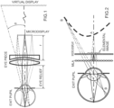
- a HMD system 100 in accordance with the present invention may include three key subsystems: I) a microscopic InI unit (micro-Inl) 130, II) a relay group 120 with a vari-focal element (VFE) 122 disposed therein for receiving the light fields from the InI unit 130, and III) eyepiece optics 110 for receiving the tuned intermediate 3D scene from the relay group 120.
- I) a microscopic InI unit (micro-Inl) 130 may include three key subsystems: I) a microscopic InI unit (micro-Inl) 130, II) a relay group 120 with a vari-focal element (VFE) 122 disposed therein for receiving the light fields from the InI unit 130, and III) eyepiece optics 110 for receiving the tuned intermediate 3D scene from the relay group 120.
- VFE vari-focal element
- the micro-InI unit 130 can reproduce the full-parallax light fields of a 3D scene seen from a constrained viewing zone, where the full-parallax light fields offer the change of view perspectives of a 3D scene from both horizontal and vertical viewing directions.
- the constrained viewing zone optically corresponds to limiting the aperture of the micro-InI unit 130, and the constrained viewing zone is optically conjugate to the exit pupil of the display system 100 where a viewer's eye is placed to view the reconstructed 3D scene.
- the relay group 120 creates an intermediate image of the 3D scene reconstructed by the micro-InI unit 130 with a tunable position of its central depth plane (CDP).
- CDP central depth plane
- the position of the CDP may be tunable in the range from about 0.5mm to as large as hundreds of millimeters to create the perception of a 3D scene with a large depth range spanning from the optical infinity (0 diopter) to as close as 20cm (5 diopters).
- the relay group 120 may also facilitate the flip of the concavity of the reconstructed 3D scene AOB.
- the eyepiece optics 110 reimages the tunable 3D light fields into a viewer's eye and enlarges the tunable depth range of the 3D light fields into a large depth volume spacing from meters far to as close as a few centimeters.
- a see-through unit (not shown), which may be optics with a beamsplitter function, may optically communicate with the eyepiece optics 110 to optically enable non-obtrusive view of a real-world scene if a see-through view is desired.
- the micro-InI unit 130 of Fig. 3A may include a high-resolution microdisplay and a micro-lens array (MI,A) 132.
- the focal length of the lenslets 133 in the MLA 132 is denoted as f MLA and the gap between the microdisplay 134 and the MLA 132 is noted as g.
- a set of 2D elemental images may be displayed on the high-resolution microdisplay 134.
- each elemental image works as a spatially-incoherent object and the conical ray bundles emitted by the pixels in the elemental images intersect and integrally create the perception of a 3D scene that appears to emit light and occupy the 3D space.
- the central depth plane (CDP) of the reconstructed miniature scene is located by the distance l cdp measured from the MLA 132.
- the light field of the reconstructed 3D scene (i.e., the curve AOB in Fig. 3B ) may be optically coupled into eyepiece optics 110 via the relay group 120 for viewing by a user.
- an aperture array 136 including a group of ray-limiting apertures that matches the pitch of the MLA 132, may be inserted between the microdisplay 134 and MLA 132.
- the small aperture corresponding to each microlens 133 allows rays within the designed viewing window to propagate through the optics and reach the eyebox while blocking unwanted rays from reaching an adjacent microlens 133 or while blocking rays from neighboring elemental images to reach a microlens 133.
- the black zone between the aperture A1 and A2 blocks the dashed rays originated from point P1 from reaching the MLA2 adjacent to the lenslet MLA1.
- FIG. 4A shows an alternative configuration to that of Fig. 4A in which the aperture array 136 is replaced by a programmable spatial light modulator (SLM) 135 so that the size and shape of each aperture can be dynamically adapted to avoid partially blocking desired rays.
- SLM spatial light modulator
- Figure 4C shows another embodiment of a micro-InI unit in accordance with the present invention in which the microdisplay 134 and aperture array 136 are replaced by a display source 131 with controllable directional emissions, where the light emission direction can be controlled precisely so that the rays from each pixel will only reach their corresponding MLA lenslet 133.
- Figure 4D demonstrates one possible configuration of such display source 131 where a spatial light modulator 135 is inserted between a backlight source 138 with non-direction emission and non-self-emissive microdisplay 137.
- the spatial light modulator 135 may be set to program and control the cone angle of the rays that illuminate the microdisplay 137 and reach the MLA 132.
- a conventional InI-based display system can typically suffer from a limited depth of field (DOF) due to the rapid degradation of spatial resolution as the depths of 3D reconstruction points shift away from that of the CDP.
- DOF depth of field
- the 3D scene volume may need to be limited to less than 0.5 diopters in order to maintain a spatial resolution of 3 arc minutes or better in the visual space.
- a relay group 120 with an electronically-controlled vari-focal element 122 sandwiched inside is inserted between the micro-InI 130 and the eyepiece 110.
- Exemplary VFE's 122 include liquid lenses, liquid crystal lenses, deformable mirrors, or any other tunable optical technology, such as electrically tunable optical technology.
- the relay group 120 By dynamically controlling the optical power, ⁇ R , of the relay group 120 by applying different voltages to the VFE 122, the relay group 120 forms an intermediate image A'O'B' of the reconstructed miniature 3D scene created by the micro-Inl 130.
- the central depth position CDP of the relayed intermediate scene is tunable axially (along the optical axis) with respect to the eyepiece 110.
- the depth volume of the magnified 3D virtual scene by the eyepiece 110 can be shifted axially from very close (e.g. 5 diopters) to very far (e.g. 0 diopter) while maintaining high lateral and longitudinal resolutions.
- Figure 5 schematically illustrates an exemplary configuration of the vari-focal relay group 120, such as the relay group 120 of Fig. 3A , including a front lens group "Front Relay” 126 adjacent to the micro-InI unit 130, VFE optics 122 located in the middle functioning as the system stop, and rear lens group "Rear Relay” 124 adjacent to the eyepiece 110.
- a front lens group "Front Relay” 126 adjacent to the micro-InI unit 130
- VFE optics 122 located in the middle functioning as the system stop
- rear lens group "Rear Relay" 124 adjacent to the eyepiece 110.
- ⁇ 1 , ⁇ VFE , and ⁇ 2 are the optical power of the front lens group 126, VFE 122, and the rear lens group 124, respectively.
- t 1 and t 2 are the spaces between the front lens group 126 and VFE 122 and between the VFE 122 and the rear lens group 124.
- z 0 is the axial distance between the front lens group and the 3D scene reconstructed by the micro-InI unit 130.
- M R 1 1 ⁇ z 0 ⁇ 1 ⁇ z 0 + 1 ⁇ z 0 ⁇ 1 t 1 ⁇ vfe ⁇ z 0 + 1 ⁇ z 0 ⁇ 1 t 1 + 1 ⁇ z 0 ⁇ 1 ⁇ z 0 + 1 ⁇ z 0 ⁇ 1 t 1 ⁇ vfe t 2 ⁇ 2
- M t M MLA ⁇ M R ⁇ z ′ RCDP z RCDP
- FOV field of view
- FOV 2 tan ⁇ 1 h 0 ⁇ 1 u vfe
- the careful position of the VFE 122 in the preferred manner ensures that the compound optical power of the relay group 120 is maintained constant, independent of the optical power of the VFE 122 due to constant chief ray directions owing to the property of object-space telecentricity.
- the subtended field angle of the display through the eyepiece 110 is further maintained constant, independent of the optical power of the VFE 122. Maintaining a constant optical power for the relay group 120 helps the virtually reconstructed 3D scene achieve constant field of view regardless of the focal depths of the CDP. Therefore a much larger volume of a 3D scene could be visually perceived without seams or artifacts in a gaze-contingent or time-multiplexing mode.
- the eyepiece 110 in Fig. 3A can take many different forms.
- a wedge-shaped freeform prism can be adopted, through which the 3D scene reconstructed by the micro-InI unit 130 and relay group 120 is magnified and viewed.
- a freeform corrector lens with one of the surfaces coated with beamsplitter coating can be attached to the freeform prism eyepiece to correct the viewing axis deviation and undesirable aberrations introduced by the freeform prism to the real-world scene.
- part of the relay group 120 may be incorporated into the eyepiece optics 110, such as freeform eyepiece, such that the tunable intermediate 3D scene is formed inside the freeform eyepiece.
- the eyepiece may be a wedge-shaped freeform waveguide prism, for example.
- Figure 6A schematically illustrates the concept of a freeform waveguide-like prism 850 formed by multiple freeform optical surfaces. The exit pupil is located where the use's eye is placed to view the magnified 3D scene.
- part of a traditional relay group 220 following the VFE 122 is incorporated into the prism 850 and fulfilled by the top portion 851 of the freeform waveguide prism 850 contained within the box labeled "Relay Group with VFE.”
- a light ray emitted from a 3D point (e.g. A) is first refracted by a closest optical element 126 of the relay group 220 and transmitted into the prism 850, followed by a reflection by one or multiple freeform surfaces to create an intermediate image (e.g. A').
- the axial position of the intermediate image (e.g. A') is tunable by the VFE 122.
- the waveguide-like eyepiece design incorporates part of the relay function, enabling a much more compact system than combining a standalone relay group 120 with a 3-surface prism.
- the waveguide-like multi-fold eyepiece design offers a much more favorable form factor, because it enables the ability to fold the remaining relay group and micro-InI unit horizontally to the temple sides. The multiple folding not only yields a much more weight-balanced system, but also enables a substantially larger see-through FOV than using a wedge-shaped prism.
- the bottom part 853 of the rear surface, marked as the eyepiece portion, of the prism 850 in Fig. 6A can be coated as a beamsplitting mirror, and a freeform corrector lens 840 including at least two freeform optical surfaces, may be attached to the rear surface of the prism 850 to correct the viewing axis deviation and undesirable aberrations introduced by the freeform prism 850 to the real-world scene.
- the see-through schematic layout is shown in Fig. 6B .
- the rays from the virtual light field are reflected by the rear surface of the prism 850 while the rays from a real-world scene are transmitted through the freeform corrector lens 840 and prism 850.
- the front surface of the freeform corrector lens 840 matches the shape of the rear surface of the prism 850.
- the back surface of the freeform corrector lens 840 may be optimized to minimize the shift and distortion introduced to the rays from a real-world scene when the lens is combined with the prism 850.
- the additional corrector lens "compensator" does not noticeably increase the footprint and weight of the overall system.
- the bottom part 853 of the rear surface, marked as the eyepiece portion, of the prism 850 in Fig. 6A may be divided into two segments, the segment 853-1 and the segment 853-2.
- the segment of 853-1 may be a reflective or partial reflective surface which receives the light fields generated by the micro-InI unit.
- a beamsplitting mirror coating on the segment of 853-1 also allows the transmission of the light rays from a real-world scene.
- the segment 853-2 is a transmissive or semi-transmissive surface which only receives the light rays from a real-world scene, while it does not receive the light fields generated by the micro-InI unit 130.
- FIG. 6D schematically illustrates a front view of the rear surface of the prism 850.
- the two surface segments, 853-1 and 853-2 intersect at an upper boundary of the aperture window required to receive the reconstructed 3D light fields by the micro-InI unit 130, and they may be made by two separate freeform surfaces.
- the division of the bottom part of the rear surface 853 into two separate segments 853-1, 853-2 with different light paths provides the ability to substantially enlarge the FOV of the see-through view beyond the FOV of the display path without being subject to the constraints of the virtual display path. As shown in Fig.
- a freeform corrector lens 840 may be attached to the rear surface of the prism 850 to correct the viewing axis deviation and undesirable aberrations introduced by the freeform prism 850 to the real-world scene.
- the rays from the virtual light field are reflected by the segment 853-1 of the rear surface of the prism 850 while the rays from a real-world scene are transmitted through both the segments 853-1 and 853-2 of the prism 850 and the freeform corrector lens 840.
- the surface segment 853-2 may be optimized to minimize visual artifacts of see-through view when it is combined with the freeform corrector lens 840.
- the front surface of the freeform corrector lens 840 matches the shape of the surface segments 853-1 and 853-2 of the prism 850.
- the back surface of the freeform corrector lens 840 may be optimized to minimize the shift and distortion introduced to the rays from a real-world scene when the freeform corrector lens 840 is combined with the prism 850.
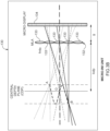
- Figure 7A schematically illustrates an optical design of a physical system that embodies the conceptual system of Fig. 6A .
- Figure 7A illustrates the 2D optical layout of the light field display path
- Fig. 7B shows the optical layout of the see-through path.
- the optical system of the light field display includes a micro-InI unit, a relay group with VFE, and a freeform waveguide. A part of the relay group may be incorporated into the waveguide.
- the Micro-InI unit may include a microdisplay S0, a pinhole array S1, and a microlens array S2.
- the relay group may include four lenses, a commercially available VFE (Electrical Lens EL 10-30 by Optotune Inc.), and two freeform surfaces (Surface S19 and S20).
- the freeform waveguide prism 900 may be formed by multiple freeform optical surfaces which are labeled as S19, S20, S21, and S22, respectively.
- part of a traditional relay group following the VFE may be incorporated into the prism 900 and fulfilled by the Surface S19 and S20.
- a light ray emitted from a 3D point (e.g. A) is first refracted by the surface S19 of the prism 900, followed by a reflection by the surface S20 to create an intermediate image (e.g. A').
- the axial position of the intermediate image (e.g. A') is tunable by the VFE.
- Two more consecutive reflections by the surfaces S21' and S22-1 and a final refraction through the surface S21 allow the ray to reach the exit pupil of the system.
- the rays reflected by the Surface S21' of the waveguide are required to satisfy the condition of total internal reflection.
- the rear surfaces S22-1, S22-2 of the prism 900 may be coated with a mirror coating for building an immersive HMD system which blocks the view of the real-world scene.
- the surface S22-1 may be coated with a beamsplitting coating if optical see-through capability is desired using the auxiliary lens, as shown in Fig. 7B .
- the Z-axis is along the viewing direction
- the Y-axis is parallel to the horizontal direction aligning with interpupilary direction
- the X-axis is in the vertical direction aligning with the head orientation.
- the overall waveguide system is symmetric about the horizontal (YOZ) plane, and the optical surfaces (S19, S20, S21, and S22) are decentered along the horizontal Y-axis and rotated about the vertical X-axis.
- the optical path is folded in the horizontal YOZ plane.
- Table 1 highlighted some of the key performance specifications for the system of Fig. 7A .
- the system offers the ability to render the true 3D light field of a 3D scene which subtends a diagonal FOV of 35° and achieves an optical resolution as high as 2 arc minutes per pixel in the visual space. Furthermore, the system offers a large depth range, tunable from 0 to 5 diopters, with a high longitudinal resolution of about 0.1 diopters for a monocular display.
- a view density of 0.5/mm 2 is equivalent to a viewing angle resolution of approximately 1 arc minute for objects at distance of 0.2 diopters.
- the exit pupil diameter for crosstalk-free viewing, also known as the eyebox of the display is about 6mm. In this embodiment, the exit pupil diameter is limited by the aperture size of the commercial VFE and it can be increased if another larger-aperture VFE is adopted.
- the system offers a large see-through FOV, greater than 65° horizontally and 40° vertically.
- the microdisplay utilized in our prototype is a 0.7" organic light emitting display (OLED) with an 8 ⁇ m color pixel and pixel resolution of 1920x1080 (ECX335A by Sony).
- OLED organic light emitting display
- the optics design itself is able to support OLED panels of different dimensions or other type of microdisplays such as liquid crystal displays that have a color pixel size greater than 6 ⁇ m.
- Tables 2 through 5 An exemplary implementation of the system of Fig. 7A is provided, Tables 2 through 5, in form of the optical surface data.
- Table 2 summarizes the basic parameters of the display path (units: mm).
- Tables 3 through 5 provide the optimized coefficients defining the non-spherical optical surfaces.
- a high resolution microdisplay with pixels as small as 6 ⁇ m is adopted to achieve a high resolution virtual reconstructed 3D image.
- a microlens array (MI,A) formed by aspherical surfaces may specifically be designed.
- the material of the MLA is PMMA. Table 3 provides the coefficients for the surfaces S1 and S2.
- the freeform waveguide prism 900 may be formed by five freeform surfaces, labeled as surface S19, S20, S21/S21', S22-1, and S22-2, respectively.
- the freeform corrector lens may be formed by two freeform surfaces, in which the front surface shares the same surface specifications as the surfaces S22-1 and S22-2 of the waveguide prism 900 and the rear surface is denoted as surface S23.
- the surface segment of S22-1 is a reflective or partial reflective surface which receives the light fields generated by the micro-InI unit. A beamsplitting mirror coating on the segment of S22-1 also allows the transmission of the light rays from a real-world scene for see-through capability.
- the surface segment S22-2 is a transmissive or semi-transmissive surface which only receives the light rays from a real-world scene, while it does not receive the light fields generated by the micro-InI unit.
- the material for both the waveguide prism and compensation lens is PMMA. Tables 4 through 8 provide the coefficients for the surfaces S19 through S21, S22-1, and S23, respectively, and Table 9 provides the surface references of each optical surface.
- the specifications for the Surface segment S22-1 were obtained after the optimization of the light field display path through the prism 900 composed of the micro-InI unit, the relay lens group, and the surfaces S19. S20, S21/21', and S22-1.
- the required aperture dimensions of Surfaces S20 and S22-1 were determined first for the light field display path. Then Surfaces S20, S21 and S22-1 were imported into 3D modeling software such as Solidworks ® from which the Surface S22-2 was created.
- the shape of the Surface S22-2 was created in the modeling software by satisfying the following requirements: (1) it intersects with Surface S22-1 along or above the upper boundary line of the required aperture for surface S22-1 defined by the display path; (2) along the intersection line between the surface S22-2 and S22-2, the surface slopes at the intersection points on the surface S22-2 approximately match, if not equal, with those corresponding points on the surface S22-1 to ensure the two surfaces to appear to be nearly continuous, which minimizes visual artifacts to the see-through view when it is combined with a matching freeform corrector lens; (3) the Surface S22-2 intersects with the surface S20 along or below the lower boundary line of the required aperture for surface S20, defined by the display path; and (4) the overall thickness between the surface S21 and S22-2 is minimized.
- a freeform shape of the Surface S22-2 is obtained in the 3D modeling software which is combined with the surfaces S19, S20, S21/21', and S22-1 to create an enclosed freeform waveguide prism.
- Fig. 7B demonstrated a substantially enlarged see-through FOV through the method described above.
- a total of 21 lenslets in the MLA were sampled with each representing 9 element image points, which added up a total of 189 field samples.
- an ideal lens with the same power as the eyepiece is placed at the exit pupil of the system (viewing window), which resulted in a cut-off frequency of 20.83 lp/mm for the final image, limited by the pixel size of the microdisplay.
- the optical performance of the designed system was assessed at representative field angles for the three design wavelengths.
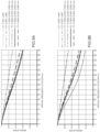
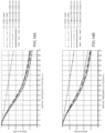
- Figures 8 through 10 plot the polychromatic modulation transfer function (MTF) for points reconstructed on the CDP set at the depth of 3, 1, and 0 diopters, respectively. For each CDP position, two sets of MTFs were plotted, one for fields corresponding to the on-axis MLA and one for fields correspond to the furthest MLA near the edge.
- MTF polychromatic modulation transfer function
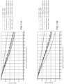
- Figures 11 through 14 plot the polychromatic MTF for reconstructed points shifted away from the CDP by 0.25, 0.5, 0.75, and 1 diopters, respectively. For each depth, two sets of MTFs were plotted, one for fields corresponding to the on-axis MLA and one for fields corresponding to the furthest MLA near the edge.
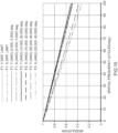
- Figure 15 plots the polychromatic MTF for the 65°x40° FOV. Across the entire the FOV, the see-through path achieved an average MTF value of over 50% at 30 cycles/degree frequency, corresponding to 20/20 normal vision, and nearly 20% at 60 cycles/degree frequency, corresponding to 20/10 vision or 0.5 arc minute of visual acuity.
Landscapes
- Physics & Mathematics (AREA)
- General Physics & Mathematics (AREA)
- Optics & Photonics (AREA)
- Lenses (AREA)
Applications Claiming Priority (2)
| Application Number | Priority Date | Filing Date | Title |
|---|---|---|---|
| US201762469097P | 2017-03-09 | 2017-03-09 | |
| PCT/US2018/021087 WO2018165117A1 (en) | 2017-03-09 | 2018-03-06 | Head-mounted light field display with integral imaging and relay optics |
Publications (3)
| Publication Number | Publication Date |
|---|---|
| EP3593195A1 EP3593195A1 (en) | 2020-01-15 |
| EP3593195A4 EP3593195A4 (en) | 2020-12-02 |
| EP3593195B1 true EP3593195B1 (en) | 2023-12-06 |
Family
ID=63449105
Family Applications (1)
| Application Number | Title | Priority Date | Filing Date |
|---|---|---|---|
| EP18763961.2A Active EP3593195B1 (en) | 2017-03-09 | 2018-03-06 | Head-mounted light field display with integral imaging and relay optics |
Country Status (9)
| Country | Link |
|---|---|
| US (1) | US12078802B2 (https=) |
| EP (1) | EP3593195B1 (https=) |
| JP (1) | JP7185303B2 (https=) |
| KR (1) | KR102687101B1 (https=) |
| CN (1) | CN110678799B (https=) |
| AU (1) | AU2018231081B2 (https=) |
| CA (1) | CA3055542A1 (https=) |
| IL (1) | IL269042B2 (https=) |
| WO (1) | WO2018165117A1 (https=) |
Families Citing this family (22)
| Publication number | Priority date | Publication date | Assignee | Title |
|---|---|---|---|---|
| CA2712059A1 (en) | 2008-01-22 | 2009-07-30 | The Arizona Board Of Regents On Behalf Of The University Of Arizona | Head-mounted projection display using reflective microdisplays |
| CN102782562B (zh) | 2010-04-30 | 2015-07-22 | 北京理工大学 | 宽视场高分辨率拼接式头盔显示装置 |
| JP6141584B2 (ja) | 2012-01-24 | 2017-06-07 | アリゾナ ボード オブ リージェンツ オン ビハーフ オブ ザ ユニバーシティ オブ アリゾナ | 小型視線追従型ヘッドマウントディスプレイ |
| US20190094424A1 (en) * | 2017-09-27 | 2019-03-28 | Cognex Corporation | Optical systems having adaptable viewing angle and working distance, and methods of making and using the same |
| JP7456583B2 (ja) * | 2018-09-28 | 2024-03-27 | ライト フィールド ラボ、インコーポレイテッド | ライトフィールドディスプレイ用ホログラフィック対象物中継部 |
| WO2020113428A1 (zh) * | 2018-12-04 | 2020-06-11 | 京东方科技集团股份有限公司 | 显示面板、显示装置和显示方法 |
| JP7320057B2 (ja) * | 2019-01-31 | 2023-08-02 | クリアル・ソシエテ・アノニム | 観察者に対する正しい単眼奥行き手がかりを持つライトフィールド複合現実システム |
| WO2021030430A1 (en) * | 2019-08-12 | 2021-02-18 | Arizona Board Of Regents On Behalf Of The University Of Arizona | Optical design and optimization techniques for 3d light field displays |
| CN112394512A (zh) * | 2019-08-16 | 2021-02-23 | 苏州苏大维格科技集团股份有限公司 | 一种头戴显示装置 |
| US11172112B2 (en) | 2019-09-09 | 2021-11-09 | Embedtek, LLC | Imaging system including a non-linear reflector |
| AU2020383516A1 (en) * | 2019-11-12 | 2022-05-26 | Light Field Lab, Inc. | Relay systems |
| US20230221557A1 (en) * | 2020-05-28 | 2023-07-13 | Arizona Board Of Regents On Behalf Of The University Of Arizona | Optical see-through head-mounted lightfield displays based on substrate-guided combiners |
| CN114185170A (zh) * | 2020-09-14 | 2022-03-15 | 中强光电股份有限公司 | 近眼光场显示装置 |
| JP7580175B2 (ja) * | 2020-09-18 | 2024-11-11 | 日本放送協会 | 要素画像群生成装置及びそのプログラム |
| WO2022112818A1 (en) * | 2020-11-24 | 2022-06-02 | Creal Sa | High-resolution light-field projector |
| JP7561018B2 (ja) * | 2020-12-03 | 2024-10-03 | 日本放送協会 | 要素画像群生成装置及びそのプログラム |
| JP2023004538A (ja) * | 2021-06-28 | 2023-01-17 | 日本放送協会 | ヘッドマウントディスプレイ |
| US12242056B2 (en) * | 2021-08-17 | 2025-03-04 | Texas Instruments Incorporated | Compact near eye display engine |
| KR20240148140A (ko) | 2023-04-03 | 2024-10-11 | 한국전자통신연구원 | 입체 영상 생성 장치 및 그것의 동작하는 방법 |
| WO2025093964A1 (en) * | 2023-10-31 | 2025-05-08 | 3M Innovative Properties Company | Folded optical system with display collimation and angular control |
| WO2025093963A1 (en) * | 2023-10-31 | 2025-05-08 | 3M Innovative Properties Company | Optical system with display collimation and angular control |
| JP7791613B1 (ja) * | 2025-01-30 | 2025-12-24 | 株式会社吉田製作所 | 歯科診療用立体視撮像装置及び歯科診療用立体視観察システム |
Citations (1)
| Publication number | Priority date | Publication date | Assignee | Title |
|---|---|---|---|---|
| WO2015134740A1 (en) * | 2014-03-05 | 2015-09-11 | Arizona Board Of Regents On Behalf Of The University Of Arizona | Wearable 3d augmented reality display with variable focus and/or object recognition |
Family Cites Families (173)
| Publication number | Priority date | Publication date | Assignee | Title |
|---|---|---|---|---|
| US3493290A (en) | 1966-01-14 | 1970-02-03 | Mitre Corp | Three-dimensional display |
| US3632184A (en) | 1970-03-02 | 1972-01-04 | Bell Telephone Labor Inc | Three-dimensional display |
| JPS503354A (https=) | 1973-05-11 | 1975-01-14 | ||
| EP0066402B1 (en) | 1981-05-29 | 1985-09-11 | Gec Avionics Limited | Night vision goggles |
| US4669810A (en) | 1984-02-03 | 1987-06-02 | Flight Dynamics, Inc. | Head up display system |
| US4753522A (en) | 1985-06-03 | 1988-06-28 | Ricoh Company, Ltd. | Plastic lens assembly for use in copying machines |
| US4863251A (en) | 1987-03-13 | 1989-09-05 | Xerox Corporation | Double gauss lens for a raster input scanner |
| US5880888A (en) | 1989-01-23 | 1999-03-09 | Hughes Aircraft Company | Helmet mounted display system |
| JPH02200074A (ja) | 1989-01-30 | 1990-08-08 | Nippon Hoso Kyokai <Nhk> | イメージインテンシファイア付固体撮像装置 |
| GB8916206D0 (en) | 1989-07-14 | 1989-11-08 | Marconi Gec Ltd | Helmet systems |
| JP2692996B2 (ja) | 1989-12-25 | 1997-12-17 | オリンパス光学工業株式会社 | 結像レンズ |
| US5109469A (en) | 1990-11-01 | 1992-04-28 | Itt Corporation | Phosphor screen for correcting luminous non-uniformity and method for making same |
| US5172275A (en) | 1990-12-14 | 1992-12-15 | Eastman Kodak Company | Apochromatic relay lens systems suitable for use in a high definition telecine apparatus |
| WO1992018971A1 (en) | 1991-04-22 | 1992-10-29 | Evans & Sutherland Computer Corp. | Head-mounted projection display system featuring beam splitter |
| DE69325607T2 (de) | 1992-04-07 | 2000-04-06 | Raytheon Co | Breites spektrales Band virtuelles Bildanzeige optisches System |
| US6008781A (en) | 1992-10-22 | 1999-12-28 | Board Of Regents Of The University Of Washington | Virtual retinal display |
| US5526183A (en) | 1993-11-29 | 1996-06-11 | Hughes Electronics | Helmet visor display employing reflective, refractive and diffractive optical elements |
| US5416315A (en) | 1994-01-24 | 1995-05-16 | Night Vision General Partnership | Visor-mounted night vision visor |
| US7262919B1 (en) | 1994-06-13 | 2007-08-28 | Canon Kabushiki Kaisha | Head-up display device with curved optical surface having total reflection |
| US5621572A (en) | 1994-08-24 | 1997-04-15 | Fergason; James L. | Optical system for a head mounted display using a retro-reflector and method of displaying an image |
| JPH08160345A (ja) | 1994-12-05 | 1996-06-21 | Olympus Optical Co Ltd | 頭部装着式ディスプレイ装置 |
| US5625495A (en) | 1994-12-07 | 1997-04-29 | U.S. Precision Lens Inc. | Telecentric lens systems for forming an image of an object composed of pixels |
| JP3658034B2 (ja) | 1995-02-28 | 2005-06-08 | キヤノン株式会社 | 画像観察光学系及び撮像光学系 |
| US5818632A (en) | 1995-04-13 | 1998-10-06 | Melles Griot, Inc | Multi-element lens system |
| JP3599828B2 (ja) | 1995-05-18 | 2004-12-08 | オリンパス株式会社 | 光学装置 |
| JP3556389B2 (ja) | 1996-05-01 | 2004-08-18 | 日本電信電話株式会社 | ヘッドマウントディスプレイ装置 |
| EP1798592A3 (en) | 1996-01-17 | 2007-09-19 | Nippon Telegraph And Telephone Corporation | Optical device and three-dimensional display device |
| JPH09218375A (ja) | 1996-02-08 | 1997-08-19 | Canon Inc | 疲労判定方法及びそれを用いた観察装置 |
| JPH09219832A (ja) | 1996-02-13 | 1997-08-19 | Olympus Optical Co Ltd | 画像表示装置 |
| US5959780A (en) | 1996-04-15 | 1999-09-28 | Olympus Optical Co., Ltd. | Head-mounted display apparatus comprising a rotationally asymmetric surface |
| US5880711A (en) | 1996-04-24 | 1999-03-09 | Sony Corporation | Three-dimensional image display method and its display apparatus |
| JP3758265B2 (ja) | 1996-04-24 | 2006-03-22 | ソニー株式会社 | 3次元画像表示方法とその表示装置 |
| US6028606A (en) | 1996-08-02 | 2000-02-22 | The Board Of Trustees Of The Leland Stanford Junior University | Camera simulation system |
| GB9618720D0 (en) | 1996-09-07 | 1996-10-16 | Philips Electronics Nv | Electrical device comprising an array of pixels |
| JP3924348B2 (ja) | 1996-11-05 | 2007-06-06 | オリンパス株式会社 | 画像表示装置 |
| US6034823A (en) | 1997-02-07 | 2000-03-07 | Olympus Optical Co., Ltd. | Decentered prism optical system |
| US6760169B2 (en) | 1997-05-07 | 2004-07-06 | Olympus Corporation | Prism optical element, image observation apparatus and image display apparatus |
| JPH10307263A (ja) | 1997-05-07 | 1998-11-17 | Olympus Optical Co Ltd | プリズム光学素子及び像観察装置 |
| DE69824440T2 (de) | 1997-11-05 | 2005-06-23 | Omd Devices L.L.C., Wilmington | Fokusfehlerkorrekturgerät |
| KR20000070909A (ko) | 1997-12-11 | 2000-11-25 | 요트.게.아. 롤페즈 | 영상 디스플레이 장치 및 이러한 장치를 포함하는 헤드가 장착된 디스플레이 |
| US6236521B1 (en) | 1998-02-09 | 2001-05-22 | Canon Kabushiki Kaisha | Objective lens and image pickup device using the same |
| US6198577B1 (en) | 1998-03-10 | 2001-03-06 | Glaxo Wellcome, Inc. | Doubly telecentric lens and imaging system for multiwell plates |
| JP3279265B2 (ja) | 1998-03-26 | 2002-04-30 | 株式会社エム・アール・システム研究所 | 画像表示装置 |
| US6704149B2 (en) | 1998-04-21 | 2004-03-09 | Minolta Co., Ltd. | Lens optical system |
| JPH11326820A (ja) | 1998-05-18 | 1999-11-26 | Olympus Optical Co Ltd | 観察光学系及びそれを用いた観察装置 |
| JP2000075240A (ja) | 1998-08-26 | 2000-03-14 | Mr System Kenkyusho:Kk | 複合表示装置 |
| JP2000199853A (ja) | 1998-10-26 | 2000-07-18 | Olympus Optical Co Ltd | 結像光学系及び観察光学系 |
| US6281862B1 (en) | 1998-11-09 | 2001-08-28 | University Of Washington | Scanned beam display with adjustable accommodation |
| JP2000171714A (ja) | 1998-12-07 | 2000-06-23 | Olympus Optical Co Ltd | 結像光学系 |
| US6433760B1 (en) | 1999-01-14 | 2002-08-13 | University Of Central Florida | Head mounted display with eyetracking capability |
| JP4550184B2 (ja) | 1999-07-02 | 2010-09-22 | オリンパス株式会社 | 観察光学系 |
| JP2000231060A (ja) | 1999-02-12 | 2000-08-22 | Olympus Optical Co Ltd | 結像光学系 |
| JP2000249974A (ja) | 1999-03-02 | 2000-09-14 | Canon Inc | 表示装置及び立体表示装置 |
| EP1465003B1 (en) | 1999-04-02 | 2008-12-31 | Olympus Corporation | Viewing optical system and image display apparatus using the same |
| EP1054280A3 (en) | 1999-05-20 | 2004-08-18 | Konica Corporation | Zoom lens |
| JP2001066543A (ja) | 1999-08-25 | 2001-03-16 | Canon Inc | 複合光学装置 |
| US6243199B1 (en) | 1999-09-07 | 2001-06-05 | Moxtek | Broad band wire grid polarizing beam splitter for use in the visible wavelength region |
| JP3391342B2 (ja) | 1999-10-29 | 2003-03-31 | ミノルタ株式会社 | 撮像レンズ装置 |
| JP2001145127A (ja) | 1999-11-12 | 2001-05-25 | Shunichi Suda | 3次元画像表示装置 |
| JP3854763B2 (ja) | 1999-11-19 | 2006-12-06 | キヤノン株式会社 | 画像表示装置 |
| KR100360592B1 (ko) | 1999-12-08 | 2002-11-13 | 동부전자 주식회사 | 반도체 장치 및 그 제조 방법 |
| JP2001238229A (ja) | 2000-02-21 | 2001-08-31 | Nippon Hoso Kyokai <Nhk> | 立体画像撮影装置及び立体画像表示装置並びに立体画像撮影表示システム |
| US20010048561A1 (en) | 2000-08-24 | 2001-12-06 | Heacock Gregory L. | Virtual imaging system for small font text |
| KR100386725B1 (ko) | 2000-07-31 | 2003-06-09 | 주식회사 대양이앤씨 | 헤드 마운트 디스플레이용 광학 시스템 |
| JP4727025B2 (ja) | 2000-08-01 | 2011-07-20 | オリンパス株式会社 | 画像表示装置 |
| JP2002055303A (ja) | 2000-08-08 | 2002-02-20 | Olympus Optical Co Ltd | 3次元偏心光路を備えた画像表示装置 |
| JP3658295B2 (ja) | 2000-08-09 | 2005-06-08 | キヤノン株式会社 | 画像表示装置 |
| AU8709801A (en) | 2000-09-07 | 2002-03-22 | Actuality Systems Inc | Volumetric three-dimensional display system |
| JP4583569B2 (ja) | 2000-09-22 | 2010-11-17 | オリンパス株式会社 | 観察光学系および撮像光学系 |
| JP4646374B2 (ja) | 2000-09-29 | 2011-03-09 | オリンパス株式会社 | 画像観察光学系 |
| US6563648B2 (en) | 2000-10-20 | 2003-05-13 | Three-Five Systems, Inc. | Compact wide field of view imaging system |
| JP2002148559A (ja) | 2000-11-15 | 2002-05-22 | Mixed Reality Systems Laboratory Inc | 画像観察装置及びそれを用いた画像観察システム |
| JP4943580B2 (ja) | 2000-12-25 | 2012-05-30 | オリンパス株式会社 | 結像光学系 |
| US20020114077A1 (en) | 2001-01-23 | 2002-08-22 | Bahram Javidi | Integral three-dimensional imaging with digital reconstruction |
| JP3658330B2 (ja) | 2001-02-21 | 2005-06-08 | キヤノン株式会社 | 複合表示装置及びそれを用いたヘッドマウントディスプレイ装置 |
| JP2002258208A (ja) | 2001-03-01 | 2002-09-11 | Mixed Reality Systems Laboratory Inc | 光学素子及びそれを用いた複合表示装置 |
| US6529331B2 (en) | 2001-04-20 | 2003-03-04 | Johns Hopkins University | Head mounted display with full field of view and high resolution |
| US6731434B1 (en) | 2001-05-23 | 2004-05-04 | University Of Central Florida | Compact lens assembly for the teleportal augmented reality system |
| US6999239B1 (en) | 2001-05-23 | 2006-02-14 | Research Foundation Of The University Of Central Florida, Inc | Head-mounted display by integration of phase-conjugate material |
| US6963454B1 (en) | 2002-03-01 | 2005-11-08 | Research Foundation Of The University Of Central Florida | Head-mounted display by integration of phase-conjugate material |
| JP4751534B2 (ja) | 2001-07-24 | 2011-08-17 | 大日本印刷株式会社 | 光学系及びそれを用いた装置 |
| JP4129972B2 (ja) | 2002-02-18 | 2008-08-06 | オリンパス株式会社 | 偏心光学系 |
| KR100509370B1 (ko) | 2002-12-30 | 2005-08-19 | 삼성테크윈 주식회사 | 촬영 렌즈 |
| DE10306578A1 (de) | 2003-02-17 | 2004-08-26 | Carl Zeiss | Anzeigevorrichtung mit elektrooptischer Fokussierung |
| CN100383598C (zh) | 2003-03-05 | 2008-04-23 | 3M创新有限公司 | 衍射透镜 |
| JP4035476B2 (ja) | 2003-04-23 | 2008-01-23 | キヤノン株式会社 | 走査光学系、走査型画像表示装置および画像表示システム |
| US7152977B2 (en) | 2003-04-24 | 2006-12-26 | Qubic Light Corporation | Solid state light engine optical system |
| US7077523B2 (en) | 2004-02-13 | 2006-07-18 | Angstorm Inc. | Three-dimensional display using variable focusing lens |
| US20070246641A1 (en) | 2004-02-27 | 2007-10-25 | Baun Kenneth W | Night vision system with video screen |
| US7339737B2 (en) | 2004-04-23 | 2008-03-04 | Microvision, Inc. | Beam multiplier that can be used as an exit-pupil expander and related system and method |
| EP1782228A1 (en) | 2004-08-03 | 2007-05-09 | Silverbrook Research Pty. Ltd | Walk-up printing |
| EP1792225A4 (en) | 2004-09-01 | 2010-07-28 | Optical Res Associates | HIGH COMPACT HEAD DISPLAY DEVICES WITH INCLINE / DECENTRE LENS ELEMENT |
| JP4639721B2 (ja) | 2004-09-22 | 2011-02-23 | 株式会社ニコン | 三次元映像表示装置 |
| JP4560368B2 (ja) | 2004-10-08 | 2010-10-13 | キヤノン株式会社 | 眼検出装置および画像表示装置 |
| US7249853B2 (en) | 2005-04-13 | 2007-07-31 | Eastman Kodak Company | Unpolished optical element with periodic surface roughness |
| US7405881B2 (en) | 2005-05-30 | 2008-07-29 | Konica Minolta Holdings, Inc. | Image display apparatus and head mount display |
| US7360905B2 (en) | 2005-06-24 | 2008-04-22 | Texas Instruments Incorporated | Compact optical engine for very small personal projectors using LED illumination |
| WO2007019347A2 (en) | 2005-08-08 | 2007-02-15 | University Of Connecticut | Depth and lateral size control of three-dimensional images in projection integral imaging |
| US20070109505A1 (en) | 2005-10-05 | 2007-05-17 | Matsushita Electric Industrial Co., Ltd. | Projection three-dimensional display apparatus |
| JP2007101930A (ja) | 2005-10-05 | 2007-04-19 | Matsushita Electric Ind Co Ltd | 立体像要素画像作成表示方法および立体像表示装置 |
| US7522344B1 (en) | 2005-12-14 | 2009-04-21 | University Of Central Florida Research Foundation, Inc. | Projection-based head-mounted display with eye-tracking capabilities |
| WO2007085682A1 (en) | 2006-01-26 | 2007-08-02 | Nokia Corporation | Eye tracker device |
| KR101255209B1 (ko) | 2006-05-04 | 2013-04-23 | 삼성전자주식회사 | 인터레이스 방식으로 영상을 디스플레이 하는 고해상도입체 영상 디스플레이 장치 |
| US20070273983A1 (en) | 2006-05-26 | 2007-11-29 | Hebert Raymond T | Devices, methods, and systems for image viewing |
| WO2007142032A1 (ja) | 2006-06-08 | 2007-12-13 | Shimadzu Corporation | 撮像装置 |
| JP2006276884A (ja) | 2006-06-16 | 2006-10-12 | Olympus Corp | 偏心プリズム光学系 |
| US7515345B2 (en) | 2006-10-09 | 2009-04-07 | Drs Sensors & Targeting Systems, Inc. | Compact objective lens assembly |
| US8259239B2 (en) | 2007-01-18 | 2012-09-04 | The Arizona Board Of Regents On Behalf Of The University Of Arizona | Polarized head-mounted projection display |
| JP4906680B2 (ja) | 2007-11-02 | 2012-03-28 | キヤノン株式会社 | 画像表示装置 |
| JP5268342B2 (ja) | 2007-12-14 | 2013-08-21 | キヤノン株式会社 | 画像表示装置 |
| US20090168010A1 (en) | 2007-12-27 | 2009-07-02 | Igor Vinogradov | Adaptive focusing using liquid crystal lens in electro-optical readers |
| CA2712059A1 (en) | 2008-01-22 | 2009-07-30 | The Arizona Board Of Regents On Behalf Of The University Of Arizona | Head-mounted projection display using reflective microdisplays |
| JP5169253B2 (ja) | 2008-01-29 | 2013-03-27 | ブラザー工業株式会社 | 画像表示装置 |
| FR2928034B1 (fr) | 2008-02-26 | 2010-03-19 | New Imaging Technologies Sas | Capteur matriciel pour tube amplificateur de lumiere |
| JP5329882B2 (ja) | 2008-09-17 | 2013-10-30 | パイオニア株式会社 | ディスプレイ装置 |
| CN101359089B (zh) | 2008-10-08 | 2010-08-11 | 北京理工大学 | 轻小型大视场自由曲面棱镜头盔显示器光学系统 |
| JP5341462B2 (ja) | 2008-10-14 | 2013-11-13 | キヤノン株式会社 | 収差補正方法、画像処理装置および画像処理システム |
| JP5464839B2 (ja) | 2008-10-31 | 2014-04-09 | キヤノン株式会社 | 画像表示装置 |
| CN101424788A (zh) | 2008-12-09 | 2009-05-06 | 中国科学院长春光学精密机械与物理研究所 | 一种眼镜式头盔显示器光学系统 |
| US8331032B2 (en) | 2009-02-19 | 2012-12-11 | Drs Rsta, Inc. | Compact objective lens assembly for simultaneously imaging multiple spectral bands |
| WO2010123934A1 (en) | 2009-04-20 | 2010-10-28 | The Arizona Board Of Regents On Behalf Of The University Of Arizona | Optical see-through free-form head-mounted display |
| US8441733B2 (en) | 2009-04-24 | 2013-05-14 | David Kessler | Pupil-expanded volumetric display |
| GB0909126D0 (en) | 2009-05-27 | 2009-07-01 | Qinetiq Ltd | Eye tracking apparatus |
| US20110075257A1 (en) | 2009-09-14 | 2011-03-31 | The Arizona Board Of Regents On Behalf Of The University Of Arizona | 3-Dimensional electro-optical see-through displays |
| JP2011085769A (ja) | 2009-10-15 | 2011-04-28 | Canon Inc | 撮像表示装置 |
| WO2011060525A1 (en) | 2009-11-19 | 2011-05-26 | Esight Corporation | Image magnification on a head mounted display |
| WO2011106797A1 (en) | 2010-02-28 | 2011-09-01 | Osterhout Group, Inc. | Projection triggering through an external marker in an augmented reality eyepiece |
| US9182596B2 (en) | 2010-02-28 | 2015-11-10 | Microsoft Technology Licensing, Llc | See-through near-eye display glasses with the optical assembly including absorptive polarizers or anti-reflective coatings to reduce stray light |
| US8467133B2 (en) | 2010-02-28 | 2013-06-18 | Osterhout Group, Inc. | See-through display with an optical assembly including a wedge-shaped illumination system |
| CN102782562B (zh) | 2010-04-30 | 2015-07-22 | 北京理工大学 | 宽视场高分辨率拼接式头盔显示装置 |
| EP2592943B1 (en) | 2010-07-16 | 2014-12-17 | McGill Technology Limited | Dispensing apparatus |
| US20120013988A1 (en) | 2010-07-16 | 2012-01-19 | Hutchin Richard A | Head mounted display having a panoramic field of view |
| US20120019557A1 (en) | 2010-07-22 | 2012-01-26 | Sony Ericsson Mobile Communications Ab | Displaying augmented reality information |
| DE102010040030B4 (de) | 2010-08-31 | 2017-02-02 | Fraunhofer-Gesellschaft zur Förderung der angewandten Forschung e.V. | Objektiv und Bildaufnahmesystem |
| JP5603716B2 (ja) * | 2010-09-06 | 2014-10-08 | オリンパス株式会社 | プリズム光学系、プリズム光学系を用いた画像表示装置及び撮像装置 |
| US8503087B1 (en) | 2010-11-02 | 2013-08-06 | Google Inc. | Structured optical surface |
| US9292973B2 (en) | 2010-11-08 | 2016-03-22 | Microsoft Technology Licensing, Llc | Automatic variable virtual focus for augmented reality displays |
| US10156722B2 (en) * | 2010-12-24 | 2018-12-18 | Magic Leap, Inc. | Methods and systems for displaying stereoscopy with a freeform optical system with addressable focus for virtual and augmented reality |
| NZ706893A (en) * | 2010-12-24 | 2017-02-24 | Magic Leap Inc | An ergonomic head mounted display device and optical system |
| US20120160302A1 (en) | 2010-12-27 | 2012-06-28 | Jeffrey Michael Citron | Trough shaped fresnel reflector solar concentrator |
| DE112012001032T5 (de) | 2011-02-28 | 2014-01-30 | Osterhout Group, Inc. | Lichtsteuerung in am Kopf zu tragenden Displays |
| TWI490587B (zh) | 2011-04-12 | 2015-07-01 | Ability Entpr Co Ltd | 光學變焦鏡頭 |
| US11640050B2 (en) | 2011-10-19 | 2023-05-02 | Epic Optix Inc. | Microdisplay-based head-up display system |
| JP6141584B2 (ja) | 2012-01-24 | 2017-06-07 | アリゾナ ボード オブ リージェンツ オン ビハーフ オブ ザ ユニバーシティ オブ アリゾナ | 小型視線追従型ヘッドマウントディスプレイ |
| JP6111635B2 (ja) | 2012-02-24 | 2017-04-12 | セイコーエプソン株式会社 | 虚像表示装置 |
| US8985803B2 (en) | 2012-03-21 | 2015-03-24 | Microsoft Technology Licensing, Llc | Freeform-prism eyepiece with illumination waveguide |
| JP6056171B2 (ja) | 2012-03-29 | 2017-01-11 | 富士通株式会社 | 立体画像表示装置及び方法 |
| US20130286053A1 (en) | 2012-04-25 | 2013-10-31 | Rod G. Fleck | Direct view augmented reality eyeglass-type display |
| US20130285885A1 (en) | 2012-04-25 | 2013-10-31 | Andreas G. Nowatzyk | Head-mounted light-field display |
| US20130300634A1 (en) | 2012-05-09 | 2013-11-14 | Nokia Corporation | Method and apparatus for determining representations of displayed information based on focus distance |
| US8754829B2 (en) | 2012-08-04 | 2014-06-17 | Paul Lapstun | Scanning light field camera and display |
| DE102013001097A1 (de) | 2012-08-10 | 2014-02-13 | Johnson Controls Gmbh | Head-up-Display und Verfahren zum Betrieb eines Head-up-Displays |
| JP6019918B2 (ja) | 2012-08-17 | 2016-11-02 | セイコーエプソン株式会社 | 虚像表示装置 |
| JP2015534108A (ja) * | 2012-09-11 | 2015-11-26 | マジック リープ, インコーポレイテッド | 人間工学的な頭部搭載型ディスプレイデバイスおよび光学システム |
| US9940901B2 (en) * | 2012-09-21 | 2018-04-10 | Nvidia Corporation | See-through optical image processing |
| CA3102710A1 (en) * | 2012-10-18 | 2014-04-24 | The Arizona Board Of Regents On Behalf Of The University Of Arizona | Stereoscopic displays with addressable focus cues |
| JP6221223B2 (ja) | 2012-11-16 | 2017-11-01 | セイコーエプソン株式会社 | 光学部材及び虚像表示装置 |
| US9858721B2 (en) | 2013-01-15 | 2018-01-02 | The University Of North Carolina At Chapel Hill | Methods, systems, and computer readable media for generating an augmented scene display |
| US9201193B1 (en) | 2013-02-18 | 2015-12-01 | Exelis, Inc. | Textured fiber optic coupled image intensified camera |
| TWI625551B (zh) * | 2013-03-15 | 2018-06-01 | 傲思丹度科技公司 | 具有改良之視角深度及解析度之三維光場顯示器及方法 |
| US9405124B2 (en) | 2013-04-09 | 2016-08-02 | Massachusetts Institute Of Technology | Methods and apparatus for light field projection |
| CN103605214A (zh) | 2013-11-21 | 2014-02-26 | 深圳市华星光电技术有限公司 | 立体显示装置 |
| KR102651578B1 (ko) | 2013-11-27 | 2024-03-25 | 매직 립, 인코포레이티드 | 가상 및 증강 현실 시스템들 및 방법들 |
| US9857591B2 (en) | 2014-05-30 | 2018-01-02 | Magic Leap, Inc. | Methods and system for creating focal planes in virtual and augmented reality |
| WO2015095737A2 (en) | 2013-12-19 | 2015-06-25 | The University Of North Carolina At Chapel Hill | Optical see-through near-eye display using point light source backlight |
| JP6264878B2 (ja) | 2013-12-24 | 2018-01-24 | セイコーエプソン株式会社 | 導光装置、虚像表示装置及び導光装置の製造方法 |
| US10244223B2 (en) | 2014-01-10 | 2019-03-26 | Ostendo Technologies, Inc. | Methods for full parallax compressed light field 3D imaging systems |
| EP4383272A3 (en) | 2014-02-21 | 2024-11-20 | The University of Akron | Imaging and display system for guiding medical interventions |
| CN111856755B (zh) * | 2014-05-30 | 2022-07-19 | 奇跃公司 | 用于显示虚拟和增强现实的立体视觉的方法和系统 |
| WO2016033317A1 (en) | 2014-08-29 | 2016-03-03 | Arizona Board Of Regent On Behalf Of The University Of Arizona | Ultra-compact head-up displays based on freeform waveguide |
| US20160239985A1 (en) | 2015-02-17 | 2016-08-18 | Osterhout Group, Inc. | See-through computer display systems |
| US10739578B2 (en) | 2016-08-12 | 2020-08-11 | The Arizona Board Of Regents On Behalf Of The University Of Arizona | High-resolution freeform eyepiece design with a large exit pupil |
| US10764552B2 (en) | 2017-05-26 | 2020-09-01 | Google Llc | Near-eye display with sparse sampling super-resolution |
-
2018
- 2018-03-06 AU AU2018231081A patent/AU2018231081B2/en not_active Expired - Fee Related
- 2018-03-06 JP JP2019548961A patent/JP7185303B2/ja active Active
- 2018-03-06 CA CA3055542A patent/CA3055542A1/en active Pending
- 2018-03-06 CN CN201880030607.0A patent/CN110678799B/zh active Active
- 2018-03-06 EP EP18763961.2A patent/EP3593195B1/en active Active
- 2018-03-06 KR KR1020197029319A patent/KR102687101B1/ko active Active
- 2018-03-06 US US16/491,836 patent/US12078802B2/en active Active
- 2018-03-06 WO PCT/US2018/021087 patent/WO2018165117A1/en not_active Ceased
- 2018-03-06 IL IL269042A patent/IL269042B2/en unknown
Patent Citations (1)
| Publication number | Priority date | Publication date | Assignee | Title |
|---|---|---|---|---|
| WO2015134740A1 (en) * | 2014-03-05 | 2015-09-11 | Arizona Board Of Regents On Behalf Of The University Of Arizona | Wearable 3d augmented reality display with variable focus and/or object recognition |
Also Published As
| Publication number | Publication date |
|---|---|
| US20200393676A1 (en) | 2020-12-17 |
| JP7185303B2 (ja) | 2022-12-07 |
| JP2020510241A (ja) | 2020-04-02 |
| CN110678799A (zh) | 2020-01-10 |
| IL269042B2 (en) | 2024-06-01 |
| US12078802B2 (en) | 2024-09-03 |
| EP3593195A4 (en) | 2020-12-02 |
| IL269042A (en) | 2019-10-31 |
| CA3055542A1 (en) | 2018-09-13 |
| KR102687101B1 (ko) | 2024-07-19 |
| AU2018231081B2 (en) | 2023-03-09 |
| KR20190131508A (ko) | 2019-11-26 |
| AU2018231081A1 (en) | 2019-09-26 |
| WO2018165117A1 (en) | 2018-09-13 |
| IL269042B1 (en) | 2024-02-01 |
| EP3593195A1 (en) | 2020-01-15 |
| CN110678799B (zh) | 2023-05-02 |
Similar Documents
| Publication | Publication Date | Title |
|---|---|---|
| EP3593195B1 (en) | Head-mounted light field display with integral imaging and relay optics | |
| EP3593196B1 (en) | Head-mounted light field display with integral imaging and waveguide prism | |
| US20250291194A1 (en) | Freeform prism and head-mounted display with increased field of view | |
| EP3769512B1 (en) | Methods of rendering light field images for integral-imaging-based light field display | |
| HK40040319A (en) | Methods of rendering light field images for integral-imaging-based light field display |
Legal Events
| Date | Code | Title | Description |
|---|---|---|---|
| STAA | Information on the status of an ep patent application or granted ep patent |
Free format text: STATUS: THE INTERNATIONAL PUBLICATION HAS BEEN MADE |
|
| PUAI | Public reference made under article 153(3) epc to a published international application that has entered the european phase |
Free format text: ORIGINAL CODE: 0009012 |
|
| STAA | Information on the status of an ep patent application or granted ep patent |
Free format text: STATUS: REQUEST FOR EXAMINATION WAS MADE |
|
| 17P | Request for examination filed |
Effective date: 20191008 |
|
| AK | Designated contracting states |
Kind code of ref document: A1 Designated state(s): AL AT BE BG CH CY CZ DE DK EE ES FI FR GB GR HR HU IE IS IT LI LT LU LV MC MK MT NL NO PL PT RO RS SE SI SK SM TR |
|
| AX | Request for extension of the european patent |
Extension state: BA ME |
|
| DAV | Request for validation of the european patent (deleted) | ||
| DAX | Request for extension of the european patent (deleted) | ||
| A4 | Supplementary search report drawn up and despatched |
Effective date: 20201103 |
|
| RIC1 | Information provided on ipc code assigned before grant |
Ipc: G02B 27/01 20060101AFI20201028BHEP Ipc: G02B 27/10 20060101ALI20201028BHEP Ipc: G02B 17/08 20060101ALI20201028BHEP Ipc: G02B 27/00 20060101ALI20201028BHEP Ipc: G02B 3/00 20060101ALI20201028BHEP Ipc: G02B 30/10 20200101ALI20201028BHEP |
|
| GRAP | Despatch of communication of intention to grant a patent |
Free format text: ORIGINAL CODE: EPIDOSNIGR1 |
|
| STAA | Information on the status of an ep patent application or granted ep patent |
Free format text: STATUS: GRANT OF PATENT IS INTENDED |
|
| INTG | Intention to grant announced |
Effective date: 20230703 |
|
| GRAS | Grant fee paid |
Free format text: ORIGINAL CODE: EPIDOSNIGR3 |
|
| GRAA | (expected) grant |
Free format text: ORIGINAL CODE: 0009210 |
|
| STAA | Information on the status of an ep patent application or granted ep patent |
Free format text: STATUS: THE PATENT HAS BEEN GRANTED |
|
| P01 | Opt-out of the competence of the unified patent court (upc) registered |
Effective date: 20231010 |
|
| AK | Designated contracting states |
Kind code of ref document: B1 Designated state(s): AL AT BE BG CH CY CZ DE DK EE ES FI FR GB GR HR HU IE IS IT LI LT LU LV MC MK MT NL NO PL PT RO RS SE SI SK SM TR |
|
| REG | Reference to a national code |
Ref country code: GB Ref legal event code: FG4D |
|
| REG | Reference to a national code |
Ref country code: CH Ref legal event code: EP |
|
| REG | Reference to a national code |
Ref country code: DE Ref legal event code: R096 Ref document number: 602018062228 Country of ref document: DE |
|
| REG | Reference to a national code |
Ref country code: IE Ref legal event code: FG4D |
|
| REG | Reference to a national code |
Ref country code: NL Ref legal event code: FP |
|
| REG | Reference to a national code |
Ref country code: LT Ref legal event code: MG9D |
|
| PG25 | Lapsed in a contracting state [announced via postgrant information from national office to epo] |
Ref country code: GR Free format text: LAPSE BECAUSE OF FAILURE TO SUBMIT A TRANSLATION OF THE DESCRIPTION OR TO PAY THE FEE WITHIN THE PRESCRIBED TIME-LIMIT Effective date: 20240307 |
|
| PG25 | Lapsed in a contracting state [announced via postgrant information from national office to epo] |
Ref country code: LT Free format text: LAPSE BECAUSE OF FAILURE TO SUBMIT A TRANSLATION OF THE DESCRIPTION OR TO PAY THE FEE WITHIN THE PRESCRIBED TIME-LIMIT Effective date: 20231206 |
|
| PG25 | Lapsed in a contracting state [announced via postgrant information from national office to epo] |
Ref country code: ES Free format text: LAPSE BECAUSE OF FAILURE TO SUBMIT A TRANSLATION OF THE DESCRIPTION OR TO PAY THE FEE WITHIN THE PRESCRIBED TIME-LIMIT Effective date: 20231206 |
|
| PG25 | Lapsed in a contracting state [announced via postgrant information from national office to epo] |
Ref country code: LT Free format text: LAPSE BECAUSE OF FAILURE TO SUBMIT A TRANSLATION OF THE DESCRIPTION OR TO PAY THE FEE WITHIN THE PRESCRIBED TIME-LIMIT Effective date: 20231206 Ref country code: GR Free format text: LAPSE BECAUSE OF FAILURE TO SUBMIT A TRANSLATION OF THE DESCRIPTION OR TO PAY THE FEE WITHIN THE PRESCRIBED TIME-LIMIT Effective date: 20240307 Ref country code: ES Free format text: LAPSE BECAUSE OF FAILURE TO SUBMIT A TRANSLATION OF THE DESCRIPTION OR TO PAY THE FEE WITHIN THE PRESCRIBED TIME-LIMIT Effective date: 20231206 Ref country code: BG Free format text: LAPSE BECAUSE OF FAILURE TO SUBMIT A TRANSLATION OF THE DESCRIPTION OR TO PAY THE FEE WITHIN THE PRESCRIBED TIME-LIMIT Effective date: 20240306 |
|
| REG | Reference to a national code |
Ref country code: AT Ref legal event code: MK05 Ref document number: 1638951 Country of ref document: AT Kind code of ref document: T Effective date: 20231206 |
|
| PG25 | Lapsed in a contracting state [announced via postgrant information from national office to epo] |
Ref country code: SE Free format text: LAPSE BECAUSE OF FAILURE TO SUBMIT A TRANSLATION OF THE DESCRIPTION OR TO PAY THE FEE WITHIN THE PRESCRIBED TIME-LIMIT Effective date: 20231206 Ref country code: RS Free format text: LAPSE BECAUSE OF FAILURE TO SUBMIT A TRANSLATION OF THE DESCRIPTION OR TO PAY THE FEE WITHIN THE PRESCRIBED TIME-LIMIT Effective date: 20231206 Ref country code: NO Free format text: LAPSE BECAUSE OF FAILURE TO SUBMIT A TRANSLATION OF THE DESCRIPTION OR TO PAY THE FEE WITHIN THE PRESCRIBED TIME-LIMIT Effective date: 20240306 Ref country code: LV Free format text: LAPSE BECAUSE OF FAILURE TO SUBMIT A TRANSLATION OF THE DESCRIPTION OR TO PAY THE FEE WITHIN THE PRESCRIBED TIME-LIMIT Effective date: 20231206 Ref country code: HR Free format text: LAPSE BECAUSE OF FAILURE TO SUBMIT A TRANSLATION OF THE DESCRIPTION OR TO PAY THE FEE WITHIN THE PRESCRIBED TIME-LIMIT Effective date: 20231206 |
|
| PG25 | Lapsed in a contracting state [announced via postgrant information from national office to epo] |
Ref country code: IS Free format text: LAPSE BECAUSE OF FAILURE TO SUBMIT A TRANSLATION OF THE DESCRIPTION OR TO PAY THE FEE WITHIN THE PRESCRIBED TIME-LIMIT Effective date: 20240406 |
|
| PG25 | Lapsed in a contracting state [announced via postgrant information from national office to epo] |
Ref country code: AT Free format text: LAPSE BECAUSE OF FAILURE TO SUBMIT A TRANSLATION OF THE DESCRIPTION OR TO PAY THE FEE WITHIN THE PRESCRIBED TIME-LIMIT Effective date: 20231206 Ref country code: CZ Free format text: LAPSE BECAUSE OF FAILURE TO SUBMIT A TRANSLATION OF THE DESCRIPTION OR TO PAY THE FEE WITHIN THE PRESCRIBED TIME-LIMIT Effective date: 20231206 |
|
| PG25 | Lapsed in a contracting state [announced via postgrant information from national office to epo] |
Ref country code: SK Free format text: LAPSE BECAUSE OF FAILURE TO SUBMIT A TRANSLATION OF THE DESCRIPTION OR TO PAY THE FEE WITHIN THE PRESCRIBED TIME-LIMIT Effective date: 20231206 |
|
| PG25 | Lapsed in a contracting state [announced via postgrant information from national office to epo] |
Ref country code: SM Free format text: LAPSE BECAUSE OF FAILURE TO SUBMIT A TRANSLATION OF THE DESCRIPTION OR TO PAY THE FEE WITHIN THE PRESCRIBED TIME-LIMIT Effective date: 20231206 Ref country code: SK Free format text: LAPSE BECAUSE OF FAILURE TO SUBMIT A TRANSLATION OF THE DESCRIPTION OR TO PAY THE FEE WITHIN THE PRESCRIBED TIME-LIMIT Effective date: 20231206 Ref country code: RO Free format text: LAPSE BECAUSE OF FAILURE TO SUBMIT A TRANSLATION OF THE DESCRIPTION OR TO PAY THE FEE WITHIN THE PRESCRIBED TIME-LIMIT Effective date: 20231206 Ref country code: IT Free format text: LAPSE BECAUSE OF FAILURE TO SUBMIT A TRANSLATION OF THE DESCRIPTION OR TO PAY THE FEE WITHIN THE PRESCRIBED TIME-LIMIT Effective date: 20231206 Ref country code: IS Free format text: LAPSE BECAUSE OF FAILURE TO SUBMIT A TRANSLATION OF THE DESCRIPTION OR TO PAY THE FEE WITHIN THE PRESCRIBED TIME-LIMIT Effective date: 20240406 Ref country code: EE Free format text: LAPSE BECAUSE OF FAILURE TO SUBMIT A TRANSLATION OF THE DESCRIPTION OR TO PAY THE FEE WITHIN THE PRESCRIBED TIME-LIMIT Effective date: 20231206 Ref country code: CZ Free format text: LAPSE BECAUSE OF FAILURE TO SUBMIT A TRANSLATION OF THE DESCRIPTION OR TO PAY THE FEE WITHIN THE PRESCRIBED TIME-LIMIT Effective date: 20231206 Ref country code: AT Free format text: LAPSE BECAUSE OF FAILURE TO SUBMIT A TRANSLATION OF THE DESCRIPTION OR TO PAY THE FEE WITHIN THE PRESCRIBED TIME-LIMIT Effective date: 20231206 |
|
| PG25 | Lapsed in a contracting state [announced via postgrant information from national office to epo] |
Ref country code: PL Free format text: LAPSE BECAUSE OF FAILURE TO SUBMIT A TRANSLATION OF THE DESCRIPTION OR TO PAY THE FEE WITHIN THE PRESCRIBED TIME-LIMIT Effective date: 20231206 Ref country code: PT Free format text: LAPSE BECAUSE OF FAILURE TO SUBMIT A TRANSLATION OF THE DESCRIPTION OR TO PAY THE FEE WITHIN THE PRESCRIBED TIME-LIMIT Effective date: 20240408 |
|
| PG25 | Lapsed in a contracting state [announced via postgrant information from national office to epo] |
Ref country code: PT Free format text: LAPSE BECAUSE OF FAILURE TO SUBMIT A TRANSLATION OF THE DESCRIPTION OR TO PAY THE FEE WITHIN THE PRESCRIBED TIME-LIMIT Effective date: 20240408 Ref country code: PL Free format text: LAPSE BECAUSE OF FAILURE TO SUBMIT A TRANSLATION OF THE DESCRIPTION OR TO PAY THE FEE WITHIN THE PRESCRIBED TIME-LIMIT Effective date: 20231206 |
|
| REG | Reference to a national code |
Ref country code: DE Ref legal event code: R097 Ref document number: 602018062228 Country of ref document: DE |
|
| PG25 | Lapsed in a contracting state [announced via postgrant information from national office to epo] |
Ref country code: DK Free format text: LAPSE BECAUSE OF FAILURE TO SUBMIT A TRANSLATION OF THE DESCRIPTION OR TO PAY THE FEE WITHIN THE PRESCRIBED TIME-LIMIT Effective date: 20231206 |
|
| PLBE | No opposition filed within time limit |
Free format text: ORIGINAL CODE: 0009261 |
|
| STAA | Information on the status of an ep patent application or granted ep patent |
Free format text: STATUS: NO OPPOSITION FILED WITHIN TIME LIMIT |
|
| PG25 | Lapsed in a contracting state [announced via postgrant information from national office to epo] |
Ref country code: SI Free format text: LAPSE BECAUSE OF FAILURE TO SUBMIT A TRANSLATION OF THE DESCRIPTION OR TO PAY THE FEE WITHIN THE PRESCRIBED TIME-LIMIT Effective date: 20231206 |
|
| PG25 | Lapsed in a contracting state [announced via postgrant information from national office to epo] |
Ref country code: SI Free format text: LAPSE BECAUSE OF FAILURE TO SUBMIT A TRANSLATION OF THE DESCRIPTION OR TO PAY THE FEE WITHIN THE PRESCRIBED TIME-LIMIT Effective date: 20231206 Ref country code: DK Free format text: LAPSE BECAUSE OF FAILURE TO SUBMIT A TRANSLATION OF THE DESCRIPTION OR TO PAY THE FEE WITHIN THE PRESCRIBED TIME-LIMIT Effective date: 20231206 |
|
| REG | Reference to a national code |
Ref country code: CH Ref legal event code: PL |
|
| 26N | No opposition filed |
Effective date: 20240909 |
|
| PG25 | Lapsed in a contracting state [announced via postgrant information from national office to epo] |
Ref country code: LU Free format text: LAPSE BECAUSE OF NON-PAYMENT OF DUE FEES Effective date: 20240306 |
|
| PG25 | Lapsed in a contracting state [announced via postgrant information from national office to epo] |
Ref country code: MC Free format text: LAPSE BECAUSE OF FAILURE TO SUBMIT A TRANSLATION OF THE DESCRIPTION OR TO PAY THE FEE WITHIN THE PRESCRIBED TIME-LIMIT Effective date: 20231206 |
|
| PG25 | Lapsed in a contracting state [announced via postgrant information from national office to epo] |
Ref country code: MC Free format text: LAPSE BECAUSE OF FAILURE TO SUBMIT A TRANSLATION OF THE DESCRIPTION OR TO PAY THE FEE WITHIN THE PRESCRIBED TIME-LIMIT Effective date: 20231206 Ref country code: LU Free format text: LAPSE BECAUSE OF NON-PAYMENT OF DUE FEES Effective date: 20240306 |
|
| PG25 | Lapsed in a contracting state [announced via postgrant information from national office to epo] |
Ref country code: IE Free format text: LAPSE BECAUSE OF NON-PAYMENT OF DUE FEES Effective date: 20240306 |
|
| PG25 | Lapsed in a contracting state [announced via postgrant information from national office to epo] |
Ref country code: IE Free format text: LAPSE BECAUSE OF NON-PAYMENT OF DUE FEES Effective date: 20240306 Ref country code: CH Free format text: LAPSE BECAUSE OF NON-PAYMENT OF DUE FEES Effective date: 20240331 |
|
| PG25 | Lapsed in a contracting state [announced via postgrant information from national office to epo] |
Ref country code: CY Free format text: LAPSE BECAUSE OF FAILURE TO SUBMIT A TRANSLATION OF THE DESCRIPTION OR TO PAY THE FEE WITHIN THE PRESCRIBED TIME-LIMIT; INVALID AB INITIO Effective date: 20180306 |
|
| PG25 | Lapsed in a contracting state [announced via postgrant information from national office to epo] |
Ref country code: HU Free format text: LAPSE BECAUSE OF FAILURE TO SUBMIT A TRANSLATION OF THE DESCRIPTION OR TO PAY THE FEE WITHIN THE PRESCRIBED TIME-LIMIT; INVALID AB INITIO Effective date: 20180306 |
|
| PG25 | Lapsed in a contracting state [announced via postgrant information from national office to epo] |
Ref country code: FI Free format text: LAPSE BECAUSE OF FAILURE TO SUBMIT A TRANSLATION OF THE DESCRIPTION OR TO PAY THE FEE WITHIN THE PRESCRIBED TIME-LIMIT Effective date: 20231207 |
|
| PG25 | Lapsed in a contracting state [announced via postgrant information from national office to epo] |
Ref country code: TR Free format text: LAPSE BECAUSE OF FAILURE TO SUBMIT A TRANSLATION OF THE DESCRIPTION OR TO PAY THE FEE WITHIN THE PRESCRIBED TIME-LIMIT Effective date: 20231206 |
|
| PGFP | Annual fee paid to national office [announced via postgrant information from national office to epo] |
Ref country code: GB Payment date: 20260327 Year of fee payment: 9 |
|
| PGFP | Annual fee paid to national office [announced via postgrant information from national office to epo] |
Ref country code: DE Payment date: 20260327 Year of fee payment: 9 |
|
| PGFP | Annual fee paid to national office [announced via postgrant information from national office to epo] |
Ref country code: BE Payment date: 20260327 Year of fee payment: 9 |
|
| PGFP | Annual fee paid to national office [announced via postgrant information from national office to epo] |
Ref country code: NL Payment date: 20260326 Year of fee payment: 9 |
|
| PGFP | Annual fee paid to national office [announced via postgrant information from national office to epo] |
Ref country code: FR Payment date: 20260325 Year of fee payment: 9 |