EP3549418B1 - Traktor - Google Patents
Traktor Download PDFInfo
- Publication number
- EP3549418B1 EP3549418B1 EP17877696.9A EP17877696A EP3549418B1 EP 3549418 B1 EP3549418 B1 EP 3549418B1 EP 17877696 A EP17877696 A EP 17877696A EP 3549418 B1 EP3549418 B1 EP 3549418B1
- Authority
- EP
- European Patent Office
- Prior art keywords
- switch
- lever
- lift lever
- lift
- tractor
- Prior art date
- Legal status (The legal status is an assumption and is not a legal conclusion. Google has not performed a legal analysis and makes no representation as to the accuracy of the status listed.)
- Active
Links
Images





Classifications
-
- A—HUMAN NECESSITIES
- A01—AGRICULTURE; FORESTRY; ANIMAL HUSBANDRY; HUNTING; TRAPPING; FISHING
- A01B—SOIL WORKING IN AGRICULTURE OR FORESTRY; PARTS, DETAILS, OR ACCESSORIES OF AGRICULTURAL MACHINES OR IMPLEMENTS, IN GENERAL
- A01B63/00—Lifting or adjusting devices or arrangements for agricultural machines or implements
- A01B63/02—Lifting or adjusting devices or arrangements for agricultural machines or implements for implements mounted on tractors
- A01B63/10—Lifting or adjusting devices or arrangements for agricultural machines or implements for implements mounted on tractors operated by hydraulic or pneumatic means
-
- A—HUMAN NECESSITIES
- A01—AGRICULTURE; FORESTRY; ANIMAL HUSBANDRY; HUNTING; TRAPPING; FISHING
- A01B—SOIL WORKING IN AGRICULTURE OR FORESTRY; PARTS, DETAILS, OR ACCESSORIES OF AGRICULTURAL MACHINES OR IMPLEMENTS, IN GENERAL
- A01B63/00—Lifting or adjusting devices or arrangements for agricultural machines or implements
-
- B—PERFORMING OPERATIONS; TRANSPORTING
- B60—VEHICLES IN GENERAL
- B60K—ARRANGEMENT OR MOUNTING OF PROPULSION UNITS OR OF TRANSMISSIONS IN VEHICLES; ARRANGEMENT OR MOUNTING OF PLURAL DIVERSE PRIME-MOVERS IN VEHICLES; AUXILIARY DRIVES FOR VEHICLES; INSTRUMENTATION OR DASHBOARDS FOR VEHICLES; ARRANGEMENTS IN CONNECTION WITH COOLING, AIR INTAKE, GAS EXHAUST OR FUEL SUPPLY OF PROPULSION UNITS IN VEHICLES
- B60K28/00—Safety devices for propulsion-unit control, specially adapted for, or arranged in, vehicles, e.g. preventing fuel supply or ignition in the event of potentially dangerous conditions
- B60K28/02—Safety devices for propulsion-unit control, specially adapted for, or arranged in, vehicles, e.g. preventing fuel supply or ignition in the event of potentially dangerous conditions responsive to conditions relating to the driver
- B60K28/04—Safety devices for propulsion-unit control, specially adapted for, or arranged in, vehicles, e.g. preventing fuel supply or ignition in the event of potentially dangerous conditions responsive to conditions relating to the driver responsive to presence or absence of the driver, e.g. to weight or lack thereof
-
- B—PERFORMING OPERATIONS; TRANSPORTING
- B62—LAND VEHICLES FOR TRAVELLING OTHERWISE THAN ON RAILS
- B62D—MOTOR VEHICLES; TRAILERS
- B62D49/00—Tractors
Definitions
- the present invention relates to a tractor, and particularly to a technique of reliably preventing actuation of a work machine at engine startup.
- Patent Literature 1 discloses an arrangement of preventing actuation of a hydraulic system at engine startup by setting conditions to be satisfied to send electricity to a hydraulic control circuit as follows: a seat switch configured to detect that an operator is seated on a driver seat is "ON"; and a lowered position detection switch configured to detect that a lift lever has been operated to a lowered position is "ON".
- Patent Application Laid-Open No. S63(1988)-186208 discloses an engine control system and working machine.
- Document JP2013129304A discloses a working vehicle.
- Document JP2000106723A discloses a hydraulic controller for mobile agricultural machine
- An object of the present invention is to provide a technique of reliably preventing actuation of a work machine at engine startup by allowing engine startup only when predetermined conditions for engine startup are satisfied.
- a tractor in which a lift valve of a hydraulic system for lifting up/down a work machine is mechanically coupled to a lift lever is arranged.
- conditions for engine startup are set as follows: a reverser lever is at a neutral position; a PTO clutch is disengaged; a seat switch is ON; and the lift lever is at a lowermost position.
- the tractor is arranged such that the lift lever at the lowermost position is contactlessly detected.
- the tractor is arranged such that: a switch driving unit is provided on a side face of the lift lever, the side face being orthogonal to a turning direction of the lift lever; a switch is provided so as to be opposed to the switch driving unit when the lift lever is turned to be at the lowermost position; and the lift lever at the lowermost position is detected by the switch.
- the tractor is arranged such that an indicator plate indicating an "engine startable position" is provided at a position corresponding to the lowermost position of the lift lever.
- actuation of the work machine at engine startup can be reliably prevented.
- FIG. 1 shows a schematic structure of a tractor 1.
- An engine 3, a front axle case 4, a transmission case 5, a cabin 6, a rear axle case 7, and the like are supported by a frame 2.
- the engine 3 is installed inside a hood 8 provided forward of the cabin 6. Power of the engine 3 is transmitted to the front axle case 4 and to the rear axle case 7 via a transmission in the transmission case 5, to drive wheels.
- a work machine 11 is attached to a rear portion of the tractor 1 via a work machine attaching device 10. Power of the engine 3 is transmitted to a power take-off (PTO) drive shaft via a PTO transmission in the transmission case 5 and via a PTO clutch, to drive the work machine 11 coupled to the PTO drive shaft.
- the work machine attaching device 10 includes: a lift link including a top link 12 and lower links 13; and lift cylinders 14. The lift link is configured to be driven by actuating the lift cylinders 14, and this enables the work machine 11 to be lifted up/down (see FIG. 2 ).
- the operation tools include: a reverser lever 22 used to change a traveling direction (forward/reverse); a PTO switch 23 used to operate the PTO clutch configured to engage/disengage power transmission to the PTO drive shaft; a lift lever 24 used to lift up/down the work machine 11; and the like.
- the reverser lever 22 is the operation tool with three positions: forward; neutral; and reverse positions.
- the traveling direction of the tractor 1 is changed by changing the position of the reverser lever 22.
- the PTO switch 23 is the operation tool with "ON" and "OFF” positions. Whether to drive the work machine 11 is selected by changing the position of the switch 23.
- the lift lever 24 is the operation tool used to change the level of the work machine 11 by extending/retracting the lift cylinders 14 of the work machine attaching device 10.
- a steering wheel 25 for steering operation of the tractor 1 a front meter panel 26 configured to display a traveling status of the tractor 1 and the like; a shift pedal 28 provided on a step 27; a lever guide panel 30 disposed to the right of the driver seat 21, through which panel 30 the PTO switch 23, the lift lever 24, a front loader operation lever 29, and the like are provided; a sub shift lever 31 provided to the left of the driver seat 21; and a hydraulic pressure adjustment knob 32 provided below the driver seat 21.
- FIG. 4 is a diagram illustrating a hydraulic system for lifting up/down the work machine 11 and shows a hydraulic circuit around the lift cylinders 14.
- Operating action to the lift lever 24 is transmitted to a rod of a lift valve 33 via an appropriate link mechanism, and this changes the position of the lift valve 33.
- the lift valve 33 is structured as a mechanical switching valve.
- Working fluid having passed through the lift valve 33 is sent to the lift cylinders 14 through a check valve 34 and a slow return valve 35.
- the tractor 1 adopts a so-called “hydraulic mechanical automatic system” to lift up/down the work machine 11, in which an operating action to the lift lever 24 mechanically drives the lift valve 33 to extend/retract the lift cylinders 14.
- the operation speed of the lift cylinders 14 is adjustable by turning the hydraulic pressure adjustment knob 32 to operate the slow return valve 35. Application of hydraulic pressure can be stopped by completely closing the slow return valve 35.
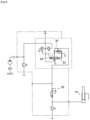
- the reverser lever 22 is provided with a switch 41 configured to detect that the position of the lever 22 is the neutral position.
- the switch 41 is designed to be “ON” when the reverser lever 22 is at the neutral position and to be “OFF” in other situations.
- the PTO switch 23 is provided with a switch 42 configured to detect that the PTO switch 23 is "OFF".
- the switch 42 is designed to be “ON” when the PTO switch 23 is “OFF”, and to be “OFF” when the PTO switch 23 is “ON”. That is, the switch 42 is configured to detect that the PTO clutch is disengaged.
- the driver seat 21 is provided with a seat switch 43 configured to detect that an operator is seated.
- the seat switch 43 is configured to determine whether the operator is seated or not by detecting a load on the driver seat 21.
- the seat switch 43 is designed to be "ON" when the load on the driver seat 21 is equal to or more than a predetermined value, and to be “OFF" when the load is less than the predetermined value.
- the lift lever 24 is provided with a sensor unit 44 configured to contactlessly detect that the position of the lever 24 is a lowermost position.
- the sensor unit 44 is configured to detect that the lift lever 24 is at the lowermost position, i.e., the lift lever 24 has been operated to a lowermost end portion.
- the sensor unit 44 includes a switch 45 designed to be "ON" when the lift lever 24 is at the lowermost position and to be “OFF” when the lever 24 is at other positions.
- a key switch 46 is provided.
- the key switch 46 is connected in series with the switch 45 of the sensor unit 44 configured to detect the position of the lift lever 24.
- the key switch 46 is disposed on a battery side relative to the switch 45.
- the key switch 46 is designed to be turned “ON” when an ignition key is turned to an engine startup position, and to be turned “OFF” when the ignition key is turned to a stop position.
- switches 41, 42, 43, 45, and 46 are connected to the battery and to a relay unit 47.
- the relay unit 47 is connected to an engine control unit (ECU) 48, which is a control device for the engine 3.
- the relay unit 47 is configured to transmit a control signal for engine startup to the ECU 48 after all the switches 41, 42, 43, 45, and 46 are turned "ON".
- the following conditions have to be satisfied to start the engine 3 by turning the ignition key: (1) the reverser lever 22 is at the neutral position, to prevent the tractor 1 from traveling in the forward or reverse direction; (2) the PTO switch 23 is "OFF", that is, the PTO clutch is disengaged to prevent actuation of the work machine 11; (3) an operator is seated on the driver seat 21; and (4) the lift lever 24 is at the lowermost position, to prevent upward movement of the work machine 11 at startup of the engine 3.
- the above configuration enables restrictions on: a traveling system of the tractor 1; a driving system of the work machine 11; and a lifting system of the work machine 11, to reliably prevent actuation of these systems at startup of the engine 3.
- the above configuration enables restriction such that no hydraulic system is actuated in the tractor 1 at startup of the engine 3.
- the conditions for the startup of the engine 3 include the seated state on the driver seat 21. Due to this, the startup of the engine 3 is not allowed in the absence of an operator on the driver seat 21.
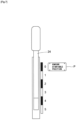
- the sensor unit 44 includes: a magnet 50 provided on a lever side face, which is a side face orthogonal to a turning direction of the lift lever 24; and a switch 45 configured to be actuated by the magnet 50 coming close to the switch 45.
- the switch 45 is provided at a position such that the switch 115 is opposed to the magnet 50 provided on the side face of the lift lever 24 when the lift lever 24 is in contact with a lever receiver 51, i.e., when the lift lever 24 is turned to be at the lowermost position.
- the switch 45 is turned “ON” when the lift lever 24 is lowered to the lowermost position to bring the magnet 50 on the lever side face close to the switch 45.
- the switch 45 is disposed on a stay 53 fixed to a frame 52.
- the magnet 50 is configured to come close to/move away from the switch 45 fixed to the stay 53 as the lift lever 24 is turned.
- the magnet 50 also functions as a switch driving unit configured to turn on the switch 45 when coming close to the switch 45.
- the stay 53 has elongated holes 54 at a portion fixed to the frame 52. Each of the holes 54 is long in the turning direction of the lift lever 24.
- the stay 53 is attached to the frame 52 using these elongated holes 54. This enables accurate positioning of the switch 45 and the lift lever 24 (the magnet 50).
- the switch 45 reacts and is turned “ON" when the magnet 50 attached to the lift lever 24 is opposed to the switch 45. That is, the sensor unit 44 adopts contactless detection, instead of known contact detection. This enables the lift lever 24 to be reliably maintained at the lowermost position without receiving a reaction force from the switch, when the lift lever 24 is operated to the lowermost position. Furthermore, it is possible to reliably detect that the lift lever 24 is at the lowermost position by the simple structure of: the magnet 50 attached to the lever side face of the lift lever 24 which is turning; and the switch 45 configured to react the magnet 50.
- an indicator plate P indicating an "engine startable position” may be attached to a position corresponding to the lowermost position of the lift lever 24. This functions as an index to start the engine 3 and makes it easier to properly position the lift lever 24.
- a lever guide for the lift lever 24 is provided with indicator labels "0", “1", “2”, “3”, and so on in a stepwise ascending manner, where "0" indicates the lowest position of the lever 24.
- the indicator plate P is provided beside the label of "0" indicating the lowermost position, for example.
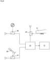
- a parking lever 60 is provided in the cabin 6.
- the parking lever 60 is used to operate a parking brake configured to brake the vehicle body of the tractor 1.
- the parking lever 60 is provided with a switch 61 configured to detect that the position of the lever 60 is “ON”.
- the switch 61 is designed to be “ON” when the parking lever 60 is at the "ON” position and to be “OFF” in other situations.
- a relay unit 62 is connected to: the switch 41 configured to detect that the reverser lever 22 is at the neutral position; the switch 42 configured to detect that the PTO switch 23 is "OFF"; the seat switch 43 configured to detect that an operator is seated on the driver seat 21; the switch 61 configured to detect that the parking lever 60 is "ON”; and the battery.
- the battery is connected via the switches 41, 42, 43, and 61.
- the relay unit 62 is configured to output a control signal for stopping the engine to the ECU 48, depending on the "ON"/"OFF” states of the switches 41, 42, 43, and 61. More specifically, the relay unit 62 is configured to transmit the control signal to the ECU 48 to stop the engine 3 when the seat switch 43 is turned “OFF” under the situation that the PTO switch 23 is "ON” (the switch 42 is “OFF”).
- the relay unit 62 is configured to transmit a control signal to the ECU 48 to keep the engine 3 running.
- the ECU 48 is controlled so that the engine 3 is not stopped but is kept running when an operator intentionally leaves the driver seat 21 under the predetermined conditions. It is possible for an operator to leave the driver seat 21 and perform external operation to the work machine 11 by allowing the operator to turn "ON" the PTO switch 23 (to engage the PTO clutch) under the above circumstances.
- a control unit 70 is connected to the seat switch 43 configured to detect that an operator is seated on the driver seat 21; the key switch 46 configured to detect the position of the ignition key; the switch 61 configured to detect that the parking lever 60 is "ON"; and the battery.
- the battery is connected via the switches 43, 45, and 61.
- the control unit 70 is configured to output a control signal for warning to a warning unit 71, depending on the "ON"/"OFF" states of the switches 43, 45, and 61. More specifically, the control unit 70 is configured to transmit the control signal to the warning unit 71 to provide notification that braking operation using the parking brake is not performed when: (1) the parking lever 60 is not pulled (the switch 61 is "OFF”); and (2) the operator leaves the driver seat 21 (the seat switch 43 is turned “OFF"), irrespective of the state of the key switch 46.
- the warning unit 71 is configured to provide visual notification using a lamp and audio notification using a beeper, for example.
- the warning unit 71 provides notification when an operator leaves the driver seat 21 with the parking brake off.
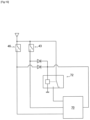
- FIG. 10 shows an example of a configuration which enables power supply from the battery even when the ignition key is "OFF".
- a timer 72 is provided.
- the timer 72 is connected to the battery in parallel with the key switch 46 and with the seat switch 43.
- the key switch 46 is turned “ON”
- voltage rises in the control unit 70 and power is supplied to the timer 72 to activate the timer 72.
- the seat switch 43 is turned “ON”
- voltage rises in the control unit 70 and power is supplied to the timer 72 to activate the timer 72.
- An input side of the timer 72 is directly connected to the battery. This makes it possible to supply power from the battery to the control unit 70 connected to an output side of the timer 72 while the timer 72 is active. That is, while the timer 72 is active because the key switch 46 and/or the seat switch 43 is "ON", it is possible to supply power from the battery to the control unit 70 via the timer 72.
- the control unit 70 outputs a self holding relay where the control unit 70 and the timer 72 constitute a closed circuit. That is, when either one of the key switch 46 and the seat switch 43 is turned “ON” to activate the timer 72 and thereby power is supplied from the battery to the control unit 70, the self holding relay is provided and kept active for a predetermined period of time, thereby to keep the timer 72 active.
- This function of the self holding circuit makes it possible to supply power to the control unit 70 for a predetermined period of time after both of the key switch 46 and the seat switch 43 are turned “OFF", and therefore enables power supply to the warning unit 71.
- the self holding relay is removed after a predetermined period of time passes. This stops the operation of the timer 72 and thereby stops the power supply to the control unit 70. As a result, power is not consumed any more, and therefore the battery does not run out.
- control unit 70 may be configured to output power for self power supply by providing such a self holding circuit inside the control unit 70, and to stop the output after a predetermined period of time.
Landscapes
- Engineering & Computer Science (AREA)
- Mechanical Engineering (AREA)
- Life Sciences & Earth Sciences (AREA)
- Chemical & Material Sciences (AREA)
- Combustion & Propulsion (AREA)
- Transportation (AREA)
- Soil Sciences (AREA)
- Environmental Sciences (AREA)
- Lifting Devices For Agricultural Implements (AREA)
- Auxiliary Drives, Propulsion Controls, And Safety Devices (AREA)
Claims (3)
- Traktor (1), in dem ein Hubventil (33) eines Hydrauliksystems zum Hoch-/Herunterheben einer Arbeitsmaschine (11) mechanisch an einen Hebehebel (24) gekoppelt ist, wobei
Bedingungen für einen Motorstart wie folgt eingestellt sind: ein Rückfahrhebel (22) befindet sich in einer neutralen Position; eine PTO-Kupplung ist ausgerückt; ein Sitzschalter (43) ist EIN; und der Hebehebel (24) befindet sich in einer untersten Position, wobei eine Anzeigeplatte (P), die eine "Motorstartposition" anzeigt, in einer Position bereitgestellt ist, die der untersten Position des Hebehebels (24) entspricht. - Traktor (1) nach Anspruch 1, wobei der Hebehebel (24) in der untersten Position kontaktlos detektiert wird.
- Traktor (1) nach Anspruch 2, wobei:auf einer Seitenfläche des Hebehebels (24) eine Schalterantriebseinheit bereitgestellt ist, wobei die Seitenfläche senkrecht zu einer Drehrichtung des Hebehebels (24) steht;ein Schalter derart bereitgestellt ist, dass er der Schalterantriebseinheit gegenüberliegt, wenn der Hebehebel in die unterste Position gedreht wird; undder Hebehebel (24) in der untersten Position vom Schalter detektiert wird.
Applications Claiming Priority (2)
| Application Number | Priority Date | Filing Date | Title |
|---|---|---|---|
| JP2016236030A JP6713633B2 (ja) | 2016-12-05 | 2016-12-05 | トラクタ |
| PCT/JP2017/043139 WO2018105497A1 (ja) | 2016-12-05 | 2017-11-30 | トラクタ |
Publications (4)
| Publication Number | Publication Date |
|---|---|
| EP3549418A1 EP3549418A1 (de) | 2019-10-09 |
| EP3549418A9 EP3549418A9 (de) | 2019-12-04 |
| EP3549418A4 EP3549418A4 (de) | 2020-01-01 |
| EP3549418B1 true EP3549418B1 (de) | 2023-12-27 |
Family
ID=62491056
Family Applications (1)
| Application Number | Title | Priority Date | Filing Date |
|---|---|---|---|
| EP17877696.9A Active EP3549418B1 (de) | 2016-12-05 | 2017-11-30 | Traktor |
Country Status (4)
| Country | Link |
|---|---|
| US (1) | US11122728B2 (de) |
| EP (1) | EP3549418B1 (de) |
| JP (1) | JP6713633B2 (de) |
| WO (1) | WO2018105497A1 (de) |
Families Citing this family (2)
| Publication number | Priority date | Publication date | Assignee | Title |
|---|---|---|---|---|
| US12118094B2 (en) * | 2019-06-27 | 2024-10-15 | Doosan Bobcat North America, Inc. | Methods and apparatus for startup processes for a power machine |
| JP7234056B2 (ja) * | 2019-06-28 | 2023-03-07 | 株式会社クボタ | 作業車両 |
Family Cites Families (24)
| Publication number | Priority date | Publication date | Assignee | Title |
|---|---|---|---|---|
| JPH0748003Y2 (ja) * | 1986-02-25 | 1995-11-08 | 三菱農機株式会社 | 圃場作業機におけるポジシヨンセツト装置 |
| JPS63186208U (de) * | 1987-05-23 | 1988-11-29 | ||
| JPH0632837Y2 (ja) * | 1989-04-05 | 1994-08-31 | 有光工業株式会社 | 背負式薬剤散布機 |
| JP2985713B2 (ja) * | 1995-02-17 | 1999-12-06 | 井関農機株式会社 | 田植機の植付部昇降制御装置 |
| JP3101543B2 (ja) * | 1995-06-30 | 2000-10-23 | 株式会社クボタ | 農用作業車 |
| JP3922820B2 (ja) * | 1998-10-05 | 2007-05-30 | 三菱農機株式会社 | 移動農機の油圧制御装置 |
| US6293077B1 (en) * | 2000-05-02 | 2001-09-25 | Mtd Products Inc | Deck attachment and lift system |
| US6316891B1 (en) * | 2000-08-15 | 2001-11-13 | Deere & Company | Interlock circuit for a lawn and garden tractor |
| JP3872997B2 (ja) * | 2000-09-14 | 2007-01-24 | 株式会社 神崎高級工機製作所 | 農用トラクタの走行制御装置 |
| JP3907581B2 (ja) * | 2002-12-13 | 2007-04-18 | 株式会社クボタ | トラクタのエンジン制御装置 |
| US6935434B1 (en) * | 2004-03-12 | 2005-08-30 | Deere & Company | Hitch control system with spring centered control lever |
| JP2007290617A (ja) * | 2006-04-26 | 2007-11-08 | Yanmar Co Ltd | エンジン制御システム及び作業機 |
| JP2007325532A (ja) * | 2006-06-07 | 2007-12-20 | Yanmar Co Ltd | ロールベーラ |
| JP5042916B2 (ja) * | 2008-05-16 | 2012-10-03 | 三菱農機株式会社 | 作業車両の制御装置 |
| JP4989588B2 (ja) * | 2008-08-26 | 2012-08-01 | 株式会社クボタ | 作業車のリフトアーム昇降構造 |
| US8171907B2 (en) * | 2009-11-19 | 2012-05-08 | Briggs And Stratton Corporation | Push button starting system for outdoor power equipment |
| US8393432B2 (en) * | 2011-03-18 | 2013-03-12 | Seats, Inc. | Vehicle seat switch actuator |
| JP2013129304A (ja) * | 2011-12-21 | 2013-07-04 | Iseki & Co Ltd | 作業車両 |
| US8924039B2 (en) * | 2012-06-29 | 2014-12-30 | Nacco Materials Handling Group, Inc. | Vehicle operator presence detector |
| JP5831504B2 (ja) * | 2013-07-03 | 2015-12-09 | 株式会社豊田自動織機 | 産業車両 |
| JP6247173B2 (ja) * | 2014-08-01 | 2017-12-13 | 株式会社クボタ | 対地作業装置のための昇降制御装置 |
| JP2016113044A (ja) * | 2014-12-16 | 2016-06-23 | デルタ工業株式会社 | 自動変速機のシフト装置 |
| JP2016200038A (ja) * | 2015-04-08 | 2016-12-01 | 井関農機株式会社 | トラクタ |
| JP6607975B2 (ja) * | 2018-01-09 | 2019-11-20 | 本田技研工業株式会社 | 車両用制御装置 |
-
2016
- 2016-12-05 JP JP2016236030A patent/JP6713633B2/ja active Active
-
2017
- 2017-11-30 WO PCT/JP2017/043139 patent/WO2018105497A1/ja not_active Ceased
- 2017-11-30 US US16/466,603 patent/US11122728B2/en active Active
- 2017-11-30 EP EP17877696.9A patent/EP3549418B1/de active Active
Also Published As
| Publication number | Publication date |
|---|---|
| WO2018105497A1 (ja) | 2018-06-14 |
| EP3549418A9 (de) | 2019-12-04 |
| US20190320573A1 (en) | 2019-10-24 |
| EP3549418A1 (de) | 2019-10-09 |
| US11122728B2 (en) | 2021-09-21 |
| JP2018088876A (ja) | 2018-06-14 |
| EP3549418A4 (de) | 2020-01-01 |
| JP6713633B2 (ja) | 2020-06-24 |
Similar Documents
| Publication | Publication Date | Title |
|---|---|---|
| EP2208630B1 (de) | Pedalblockierungssteuerung für ein nutzfahrzeug | |
| EP2138742B1 (de) | Fahrzeug mit fahrzeugsteuerungseinheit | |
| US6581738B2 (en) | Parking lock for a motor vehicle with an emergency release device | |
| US9650024B2 (en) | Vehicle control system | |
| US10710566B2 (en) | Powered vehicle including a SAHR brake | |
| US20100332093A1 (en) | Vehicle control unit and vehicle equipped with the same | |
| EP3549418B1 (de) | Traktor | |
| JPH02179549A (ja) | 変速機の操作装置 | |
| KR101007484B1 (ko) | 엔진지게차의 안전제어방법 | |
| JP7022781B2 (ja) | トラクタ | |
| EP2202110B1 (de) | Pedalblockierungssteuerung für ein nutzfahrzeug | |
| JP4961935B2 (ja) | トラクタ用pto制御装置 | |
| JP6402970B2 (ja) | Pto搭載車両 | |
| EP2809547B1 (de) | Verfahren zur betätigung einer bremsleuchte einer hydraulisch angetriebenen arbeitsmaschine | |
| JP4453260B2 (ja) | 作業車両 | |
| US20260068800A1 (en) | Agricultural work vehicle and control method therefor | |
| JPH02197424A (ja) | 車両用動力取出装置 | |
| JP2003211992A (ja) | 移動農機の液晶表示装置 | |
| BR112020007583B1 (pt) | Sistema de parada de emergência para um veículo | |
| JP3968517B2 (ja) | トラクタ | |
| JPH09226411A (ja) | 車両における変速機の補助動力取出装置 | |
| KR101611729B1 (ko) | 파킹 폴의 제어 장치 및 제어 방법 | |
| JP5916442B2 (ja) | スラグダンプトラック | |
| JP2000337504A (ja) | 作業車両の変速制御装置 | |
| JP2007092877A (ja) | 作業車両のクラッチ操作装置 |
Legal Events
| Date | Code | Title | Description |
|---|---|---|---|
| STAA | Information on the status of an ep patent application or granted ep patent |
Free format text: STATUS: THE INTERNATIONAL PUBLICATION HAS BEEN MADE |
|
| PUAI | Public reference made under article 153(3) epc to a published international application that has entered the european phase |
Free format text: ORIGINAL CODE: 0009012 |
|
| STAA | Information on the status of an ep patent application or granted ep patent |
Free format text: STATUS: REQUEST FOR EXAMINATION WAS MADE |
|
| 17P | Request for examination filed |
Effective date: 20190624 |
|
| AK | Designated contracting states |
Kind code of ref document: A1 Designated state(s): AL AT BE BG CH CY CZ DE DK EE ES FI FR GB GR HR HU IE IS IT LI LT LU LV MC MK MT NL NO PL PT RO RS SE SI SK SM TR |
|
| AX | Request for extension of the european patent |
Extension state: BA ME |
|
| A4 | Supplementary search report drawn up and despatched |
Effective date: 20191202 |
|
| RIC1 | Information provided on ipc code assigned before grant |
Ipc: A01B 63/00 20060101AFI20191126BHEP Ipc: B62D 49/00 20060101ALI20191126BHEP Ipc: A01B 63/10 20060101ALI20191126BHEP Ipc: B60K 28/04 20060101ALI20191126BHEP |
|
| DAV | Request for validation of the european patent (deleted) | ||
| DAX | Request for extension of the european patent (deleted) | ||
| RAP1 | Party data changed (applicant data changed or rights of an application transferred) |
Owner name: YANMAR POWER TECHNOLOGY CO., LTD. |
|
| STAA | Information on the status of an ep patent application or granted ep patent |
Free format text: STATUS: EXAMINATION IS IN PROGRESS |
|
| 17Q | First examination report despatched |
Effective date: 20211221 |
|
| GRAP | Despatch of communication of intention to grant a patent |
Free format text: ORIGINAL CODE: EPIDOSNIGR1 |
|
| STAA | Information on the status of an ep patent application or granted ep patent |
Free format text: STATUS: GRANT OF PATENT IS INTENDED |
|
| INTG | Intention to grant announced |
Effective date: 20230202 |
|
| GRAJ | Information related to disapproval of communication of intention to grant by the applicant or resumption of examination proceedings by the epo deleted |
Free format text: ORIGINAL CODE: EPIDOSDIGR1 |
|
| STAA | Information on the status of an ep patent application or granted ep patent |
Free format text: STATUS: EXAMINATION IS IN PROGRESS |
|
| INTC | Intention to grant announced (deleted) | ||
| GRAP | Despatch of communication of intention to grant a patent |
Free format text: ORIGINAL CODE: EPIDOSNIGR1 |
|
| STAA | Information on the status of an ep patent application or granted ep patent |
Free format text: STATUS: GRANT OF PATENT IS INTENDED |
|
| INTG | Intention to grant announced |
Effective date: 20230710 |
|
| GRAS | Grant fee paid |
Free format text: ORIGINAL CODE: EPIDOSNIGR3 |
|
| GRAA | (expected) grant |
Free format text: ORIGINAL CODE: 0009210 |
|
| STAA | Information on the status of an ep patent application or granted ep patent |
Free format text: STATUS: THE PATENT HAS BEEN GRANTED |
|
| AK | Designated contracting states |
Kind code of ref document: B1 Designated state(s): AL AT BE BG CH CY CZ DE DK EE ES FI FR GB GR HR HU IE IS IT LI LT LU LV MC MK MT NL NO PL PT RO RS SE SI SK SM TR |
|
| REG | Reference to a national code |
Ref country code: GB Ref legal event code: FG4D |
|
| REG | Reference to a national code |
Ref country code: CH Ref legal event code: EP |
|
| REG | Reference to a national code |
Ref country code: DE Ref legal event code: R096 Ref document number: 602017078004 Country of ref document: DE |
|
| REG | Reference to a national code |
Ref country code: IE Ref legal event code: FG4D |
|
| PG25 | Lapsed in a contracting state [announced via postgrant information from national office to epo] |
Ref country code: GR Free format text: LAPSE BECAUSE OF FAILURE TO SUBMIT A TRANSLATION OF THE DESCRIPTION OR TO PAY THE FEE WITHIN THE PRESCRIBED TIME-LIMIT Effective date: 20240328 |
|
| REG | Reference to a national code |
Ref country code: LT Ref legal event code: MG9D |
|
| PG25 | Lapsed in a contracting state [announced via postgrant information from national office to epo] |
Ref country code: LT Free format text: LAPSE BECAUSE OF FAILURE TO SUBMIT A TRANSLATION OF THE DESCRIPTION OR TO PAY THE FEE WITHIN THE PRESCRIBED TIME-LIMIT Effective date: 20231227 |
|
| PG25 | Lapsed in a contracting state [announced via postgrant information from national office to epo] |
Ref country code: ES Free format text: LAPSE BECAUSE OF FAILURE TO SUBMIT A TRANSLATION OF THE DESCRIPTION OR TO PAY THE FEE WITHIN THE PRESCRIBED TIME-LIMIT Effective date: 20231227 |
|
| PG25 | Lapsed in a contracting state [announced via postgrant information from national office to epo] |
Ref country code: LT Free format text: LAPSE BECAUSE OF FAILURE TO SUBMIT A TRANSLATION OF THE DESCRIPTION OR TO PAY THE FEE WITHIN THE PRESCRIBED TIME-LIMIT Effective date: 20231227 Ref country code: GR Free format text: LAPSE BECAUSE OF FAILURE TO SUBMIT A TRANSLATION OF THE DESCRIPTION OR TO PAY THE FEE WITHIN THE PRESCRIBED TIME-LIMIT Effective date: 20240328 Ref country code: FI Free format text: LAPSE BECAUSE OF FAILURE TO SUBMIT A TRANSLATION OF THE DESCRIPTION OR TO PAY THE FEE WITHIN THE PRESCRIBED TIME-LIMIT Effective date: 20231227 Ref country code: ES Free format text: LAPSE BECAUSE OF FAILURE TO SUBMIT A TRANSLATION OF THE DESCRIPTION OR TO PAY THE FEE WITHIN THE PRESCRIBED TIME-LIMIT Effective date: 20231227 Ref country code: BG Free format text: LAPSE BECAUSE OF FAILURE TO SUBMIT A TRANSLATION OF THE DESCRIPTION OR TO PAY THE FEE WITHIN THE PRESCRIBED TIME-LIMIT Effective date: 20240327 |
|
| REG | Reference to a national code |
Ref country code: NL Ref legal event code: MP Effective date: 20231227 |
|
| REG | Reference to a national code |
Ref country code: AT Ref legal event code: MK05 Ref document number: 1643613 Country of ref document: AT Kind code of ref document: T Effective date: 20231227 |
|
| PG25 | Lapsed in a contracting state [announced via postgrant information from national office to epo] |
Ref country code: NL Free format text: LAPSE BECAUSE OF FAILURE TO SUBMIT A TRANSLATION OF THE DESCRIPTION OR TO PAY THE FEE WITHIN THE PRESCRIBED TIME-LIMIT Effective date: 20231227 |
|
| PG25 | Lapsed in a contracting state [announced via postgrant information from national office to epo] |
Ref country code: SE Free format text: LAPSE BECAUSE OF FAILURE TO SUBMIT A TRANSLATION OF THE DESCRIPTION OR TO PAY THE FEE WITHIN THE PRESCRIBED TIME-LIMIT Effective date: 20231227 Ref country code: RS Free format text: LAPSE BECAUSE OF FAILURE TO SUBMIT A TRANSLATION OF THE DESCRIPTION OR TO PAY THE FEE WITHIN THE PRESCRIBED TIME-LIMIT Effective date: 20231227 Ref country code: NO Free format text: LAPSE BECAUSE OF FAILURE TO SUBMIT A TRANSLATION OF THE DESCRIPTION OR TO PAY THE FEE WITHIN THE PRESCRIBED TIME-LIMIT Effective date: 20240327 Ref country code: NL Free format text: LAPSE BECAUSE OF FAILURE TO SUBMIT A TRANSLATION OF THE DESCRIPTION OR TO PAY THE FEE WITHIN THE PRESCRIBED TIME-LIMIT Effective date: 20231227 Ref country code: LV Free format text: LAPSE BECAUSE OF FAILURE TO SUBMIT A TRANSLATION OF THE DESCRIPTION OR TO PAY THE FEE WITHIN THE PRESCRIBED TIME-LIMIT Effective date: 20231227 Ref country code: HR Free format text: LAPSE BECAUSE OF FAILURE TO SUBMIT A TRANSLATION OF THE DESCRIPTION OR TO PAY THE FEE WITHIN THE PRESCRIBED TIME-LIMIT Effective date: 20231227 |
|
| PG25 | Lapsed in a contracting state [announced via postgrant information from national office to epo] |
Ref country code: IS Free format text: LAPSE BECAUSE OF FAILURE TO SUBMIT A TRANSLATION OF THE DESCRIPTION OR TO PAY THE FEE WITHIN THE PRESCRIBED TIME-LIMIT Effective date: 20240427 |
|
| PG25 | Lapsed in a contracting state [announced via postgrant information from national office to epo] |
Ref country code: CZ Free format text: LAPSE BECAUSE OF FAILURE TO SUBMIT A TRANSLATION OF THE DESCRIPTION OR TO PAY THE FEE WITHIN THE PRESCRIBED TIME-LIMIT Effective date: 20231227 Ref country code: AT Free format text: LAPSE BECAUSE OF FAILURE TO SUBMIT A TRANSLATION OF THE DESCRIPTION OR TO PAY THE FEE WITHIN THE PRESCRIBED TIME-LIMIT Effective date: 20231227 |
|
| PG25 | Lapsed in a contracting state [announced via postgrant information from national office to epo] |
Ref country code: SK Free format text: LAPSE BECAUSE OF FAILURE TO SUBMIT A TRANSLATION OF THE DESCRIPTION OR TO PAY THE FEE WITHIN THE PRESCRIBED TIME-LIMIT Effective date: 20231227 |
|
| PG25 | Lapsed in a contracting state [announced via postgrant information from national office to epo] |
Ref country code: SM Free format text: LAPSE BECAUSE OF FAILURE TO SUBMIT A TRANSLATION OF THE DESCRIPTION OR TO PAY THE FEE WITHIN THE PRESCRIBED TIME-LIMIT Effective date: 20231227 Ref country code: SK Free format text: LAPSE BECAUSE OF FAILURE TO SUBMIT A TRANSLATION OF THE DESCRIPTION OR TO PAY THE FEE WITHIN THE PRESCRIBED TIME-LIMIT Effective date: 20231227 Ref country code: RO Free format text: LAPSE BECAUSE OF FAILURE TO SUBMIT A TRANSLATION OF THE DESCRIPTION OR TO PAY THE FEE WITHIN THE PRESCRIBED TIME-LIMIT Effective date: 20231227 Ref country code: IT Free format text: LAPSE BECAUSE OF FAILURE TO SUBMIT A TRANSLATION OF THE DESCRIPTION OR TO PAY THE FEE WITHIN THE PRESCRIBED TIME-LIMIT Effective date: 20231227 Ref country code: IS Free format text: LAPSE BECAUSE OF FAILURE TO SUBMIT A TRANSLATION OF THE DESCRIPTION OR TO PAY THE FEE WITHIN THE PRESCRIBED TIME-LIMIT Effective date: 20240427 Ref country code: EE Free format text: LAPSE BECAUSE OF FAILURE TO SUBMIT A TRANSLATION OF THE DESCRIPTION OR TO PAY THE FEE WITHIN THE PRESCRIBED TIME-LIMIT Effective date: 20231227 Ref country code: CZ Free format text: LAPSE BECAUSE OF FAILURE TO SUBMIT A TRANSLATION OF THE DESCRIPTION OR TO PAY THE FEE WITHIN THE PRESCRIBED TIME-LIMIT Effective date: 20231227 Ref country code: AT Free format text: LAPSE BECAUSE OF FAILURE TO SUBMIT A TRANSLATION OF THE DESCRIPTION OR TO PAY THE FEE WITHIN THE PRESCRIBED TIME-LIMIT Effective date: 20231227 |
|
| PG25 | Lapsed in a contracting state [announced via postgrant information from national office to epo] |
Ref country code: PT Free format text: LAPSE BECAUSE OF FAILURE TO SUBMIT A TRANSLATION OF THE DESCRIPTION OR TO PAY THE FEE WITHIN THE PRESCRIBED TIME-LIMIT Effective date: 20240429 Ref country code: PL Free format text: LAPSE BECAUSE OF FAILURE TO SUBMIT A TRANSLATION OF THE DESCRIPTION OR TO PAY THE FEE WITHIN THE PRESCRIBED TIME-LIMIT Effective date: 20231227 |
|
| PG25 | Lapsed in a contracting state [announced via postgrant information from national office to epo] |
Ref country code: PT Free format text: LAPSE BECAUSE OF FAILURE TO SUBMIT A TRANSLATION OF THE DESCRIPTION OR TO PAY THE FEE WITHIN THE PRESCRIBED TIME-LIMIT Effective date: 20240429 Ref country code: PL Free format text: LAPSE BECAUSE OF FAILURE TO SUBMIT A TRANSLATION OF THE DESCRIPTION OR TO PAY THE FEE WITHIN THE PRESCRIBED TIME-LIMIT Effective date: 20231227 |
|
| REG | Reference to a national code |
Ref country code: DE Ref legal event code: R097 Ref document number: 602017078004 Country of ref document: DE |
|
| PG25 | Lapsed in a contracting state [announced via postgrant information from national office to epo] |
Ref country code: DK Free format text: LAPSE BECAUSE OF FAILURE TO SUBMIT A TRANSLATION OF THE DESCRIPTION OR TO PAY THE FEE WITHIN THE PRESCRIBED TIME-LIMIT Effective date: 20231227 |
|
| PG25 | Lapsed in a contracting state [announced via postgrant information from national office to epo] |
Ref country code: DK Free format text: LAPSE BECAUSE OF FAILURE TO SUBMIT A TRANSLATION OF THE DESCRIPTION OR TO PAY THE FEE WITHIN THE PRESCRIBED TIME-LIMIT Effective date: 20231227 |
|
| PLBE | No opposition filed within time limit |
Free format text: ORIGINAL CODE: 0009261 |
|
| STAA | Information on the status of an ep patent application or granted ep patent |
Free format text: STATUS: NO OPPOSITION FILED WITHIN TIME LIMIT |
|
| 26N | No opposition filed |
Effective date: 20240930 |
|
| PG25 | Lapsed in a contracting state [announced via postgrant information from national office to epo] |
Ref country code: SI Free format text: LAPSE BECAUSE OF FAILURE TO SUBMIT A TRANSLATION OF THE DESCRIPTION OR TO PAY THE FEE WITHIN THE PRESCRIBED TIME-LIMIT Effective date: 20231227 |
|
| REG | Reference to a national code |
Ref country code: CH Ref legal event code: PL |
|
| PG25 | Lapsed in a contracting state [announced via postgrant information from national office to epo] |
Ref country code: MC Free format text: LAPSE BECAUSE OF FAILURE TO SUBMIT A TRANSLATION OF THE DESCRIPTION OR TO PAY THE FEE WITHIN THE PRESCRIBED TIME-LIMIT Effective date: 20231227 |
|
| PG25 | Lapsed in a contracting state [announced via postgrant information from national office to epo] |
Ref country code: LU Free format text: LAPSE BECAUSE OF NON-PAYMENT OF DUE FEES Effective date: 20241130 |
|
| REG | Reference to a national code |
Ref country code: CH Ref legal event code: PL |
|
| GBPC | Gb: european patent ceased through non-payment of renewal fee |
Effective date: 20241130 |
|
| PG25 | Lapsed in a contracting state [announced via postgrant information from national office to epo] |
Ref country code: CH Free format text: LAPSE BECAUSE OF NON-PAYMENT OF DUE FEES Effective date: 20241130 |
|
| REG | Reference to a national code |
Ref country code: BE Ref legal event code: MM Effective date: 20241130 |
|
| PG25 | Lapsed in a contracting state [announced via postgrant information from national office to epo] |
Ref country code: GB Free format text: LAPSE BECAUSE OF NON-PAYMENT OF DUE FEES Effective date: 20241130 Ref country code: BE Free format text: LAPSE BECAUSE OF NON-PAYMENT OF DUE FEES Effective date: 20241130 |
|
| PG25 | Lapsed in a contracting state [announced via postgrant information from national office to epo] |
Ref country code: IE Free format text: LAPSE BECAUSE OF NON-PAYMENT OF DUE FEES Effective date: 20241130 |
|
| PGFP | Annual fee paid to national office [announced via postgrant information from national office to epo] |
Ref country code: DE Payment date: 20251119 Year of fee payment: 9 |
|
| PGFP | Annual fee paid to national office [announced via postgrant information from national office to epo] |
Ref country code: FR Payment date: 20251126 Year of fee payment: 9 |
|
| PG25 | Lapsed in a contracting state [announced via postgrant information from national office to epo] |
Ref country code: CY Free format text: LAPSE BECAUSE OF FAILURE TO SUBMIT A TRANSLATION OF THE DESCRIPTION OR TO PAY THE FEE WITHIN THE PRESCRIBED TIME-LIMIT; INVALID AB INITIO Effective date: 20171130 |