EP3463972B1 - Keder, sitzbezug und sitz mit einem sitzbezug - Google Patents
Keder, sitzbezug und sitz mit einem sitzbezug Download PDFInfo
- Publication number
- EP3463972B1 EP3463972B1 EP17725257.4A EP17725257A EP3463972B1 EP 3463972 B1 EP3463972 B1 EP 3463972B1 EP 17725257 A EP17725257 A EP 17725257A EP 3463972 B1 EP3463972 B1 EP 3463972B1
- Authority
- EP
- European Patent Office
- Prior art keywords
- seat
- cover
- welt
- seat cover
- edge strip
- Prior art date
- Legal status (The legal status is an assumption and is not a legal conclusion. Google has not performed a legal analysis and makes no representation as to the accuracy of the status listed.)
- Active
Links
Images


Classifications
-
- B—PERFORMING OPERATIONS; TRANSPORTING
- B60—VEHICLES IN GENERAL
- B60N—SEATS SPECIALLY ADAPTED FOR VEHICLES; VEHICLE PASSENGER ACCOMMODATION NOT OTHERWISE PROVIDED FOR
- B60N2/00—Seats specially adapted for vehicles; Arrangement or mounting of seats in vehicles
- B60N2/58—Seat coverings
- B60N2/5816—Seat coverings attachments thereof
- B60N2/5825—Seat coverings attachments thereof by hooks, staples, clips, snap fasteners or the like
-
- A—HUMAN NECESSITIES
- A47—FURNITURE; DOMESTIC ARTICLES OR APPLIANCES; COFFEE MILLS; SPICE MILLS; SUCTION CLEANERS IN GENERAL
- A47C—CHAIRS; SOFAS; BEDS
- A47C31/00—Details or accessories for chairs, beds, or the like, not provided for in other groups of this subclass, e.g. upholstery fasteners, mattress protectors, stretching devices for mattress nets
- A47C31/02—Upholstery attaching means
-
- B—PERFORMING OPERATIONS; TRANSPORTING
- B60—VEHICLES IN GENERAL
- B60N—SEATS SPECIALLY ADAPTED FOR VEHICLES; VEHICLE PASSENGER ACCOMMODATION NOT OTHERWISE PROVIDED FOR
- B60N2/00—Seats specially adapted for vehicles; Arrangement or mounting of seats in vehicles
- B60N2/58—Seat coverings
- B60N2/5816—Seat coverings attachments thereof
- B60N2/5833—Seat coverings attachments thereof by hook-and-loop type fasteners
-
- A—HUMAN NECESSITIES
- A47—FURNITURE; DOMESTIC ARTICLES OR APPLIANCES; COFFEE MILLS; SPICE MILLS; SUCTION CLEANERS IN GENERAL
- A47C—CHAIRS; SOFAS; BEDS
- A47C31/00—Details or accessories for chairs, beds, or the like, not provided for in other groups of this subclass, e.g. upholstery fasteners, mattress protectors, stretching devices for mattress nets
- A47C31/02—Upholstery attaching means
- A47C31/023—Upholstery attaching means connecting upholstery to frames, e.g. by hooks, clips, snap fasteners, clamping means or the like
-
- B—PERFORMING OPERATIONS; TRANSPORTING
- B60—VEHICLES IN GENERAL
- B60N—SEATS SPECIALLY ADAPTED FOR VEHICLES; VEHICLE PASSENGER ACCOMMODATION NOT OTHERWISE PROVIDED FOR
- B60N2/00—Seats specially adapted for vehicles; Arrangement or mounting of seats in vehicles
- B60N2/58—Seat coverings
- B60N2/5816—Seat coverings attachments thereof
-
- B—PERFORMING OPERATIONS; TRANSPORTING
- B60—VEHICLES IN GENERAL
- B60N—SEATS SPECIALLY ADAPTED FOR VEHICLES; VEHICLE PASSENGER ACCOMMODATION NOT OTHERWISE PROVIDED FOR
- B60N2/00—Seats specially adapted for vehicles; Arrangement or mounting of seats in vehicles
- B60N2/58—Seat coverings
- B60N2/60—Removable protective coverings
- B60N2/6018—Removable protective coverings attachments thereof
-
- B—PERFORMING OPERATIONS; TRANSPORTING
- B60—VEHICLES IN GENERAL
- B60N—SEATS SPECIALLY ADAPTED FOR VEHICLES; VEHICLE PASSENGER ACCOMMODATION NOT OTHERWISE PROVIDED FOR
- B60N2/00—Seats specially adapted for vehicles; Arrangement or mounting of seats in vehicles
- B60N2/58—Seat coverings
- B60N2/60—Removable protective coverings
- B60N2/6018—Removable protective coverings attachments thereof
- B60N2/6036—Removable protective coverings attachments thereof by hook and loop-type fasteners
Definitions
- the invention relates to a seat, in particular a vehicle seat.
- a seat such as a vehicle seat, is usually provided with a seat cover. It is also known to releasably attach the seat cover to the seat in order to remove or replace the seat cover, for example. For this purpose it is known, for example, to provide the seat cover and correspondingly the seat on the surface side with fastening means, such as for example a Velcro tape and, on the opposite side, a loop tape.
- fastening means such as for example a Velcro tape and, on the opposite side, a loop tape.
- the invention is based on the object of specifying a seat with a seat cover.
- a seat according to the invention in particular a vehicle seat, comprises a seat cushion, a lower seat cover attached to the seat cushion and an upper seat cover which can be releasably attached to the lower seat cover.
- One of the seat covers is provided with at least one piping, which comprises a piping core that is surrounded by a fastening material, the other seat cover being provided with a holding material in which the fastening material of the piping engages in the connected state.
- an individual seat By choosing a certain seat cover, in particular its material, an individual seat can be created.
- different decorative seats or seats with different seating properties with seat heating and / or ventilation and / or with room climate zones can be created in this way.
- the welt core is sheathed by the fastening material.
- the fastening material is designed, for example, as a Velcro material.
- the piping is designed as a fastening and / or edge reinforcement piping and is made possible by incorporating it into a seat cover compared to conventionally applied connecting means, such as. B. glued-on Velcro strips, a visually appealing, especially smooth or wrinkle-free seat cover.
- the Velcro material is a hook material, in particular a hook, mushroom head or eye tape / - would.
- the Velcro material can also be designed as a fleece material.
- the fastening material can be attached to the welt core by means of a material bond.
- the fastening material is glued or welded to the welt core.
- the fastening material can also be self-adhesive, for example by means of a pressure-sensitive adhesive coating on a side facing the piping core, a shear force of the pressure-sensitive adhesive coating being greater than a shear force of the releasable connection between the fastening material and an adhesive material arranged on the seat cover.
- a cover material is arranged between the fastening material and the welt core.
- the cover material serves, on the one hand, to conceal the piping core.
- the cover material is used to fasten the welt, for example, to a seat part, in particular a seat surface or to a lower seat cover.
- the cover material encases the welt core and is glued or sewn at its ends to form a welt flap.
- the fastening material here is connected to the cover material and encases the cover material that encases the piping core.
- the fastening material can be firmly connected to the cover material.
- the fastening material is glued or welded to the cover material.
- the fastening material can also be sewn to the cover material.
- the fastening material directly encases the welt core and forms a welt flap at its ends.
- the welt core is preferably formed from an elastic material, in particular from plastic or rubber. This enables pleasant sitting comfort for a person sitting on the seat cover.
- the cover material is made of plastic, e.g. B. polypropylene, or a natural material formed. The cover material is in particular made stronger than the welt core.
- a plurality of cover parts is provided for the seat cover, with at least one piping being provided in the area of at least two cover parts connected to one another.
- the holding material is a fleece material which creates a detachable connection with a Velcro material designed as a hook material.
- the holding material can also be a hook material, the fastening material being a loop material or fleece material.
- the holding material can be materially connected to the seat cover.
- the holding material is glued or welded to the seat cover.
- the holding material can also be sewn to the seat cover.
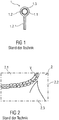
- FIG. 1 shows schematically in section an exemplary embodiment for a welt 1 according to the prior art.
- Keder 1 are used in the automotive sector.
- the welt 1 is generally used to cover, for example, visible joints between two parts, such as between seat cover parts or parts of a trim part.
- the piping 1 is also used in the transition area of parts, for example to enable a flowing transition without the annoying impression of joints.
- the aesthetic appearance of a component, such as that of a seat or seat cover is thus embellished.
- the welt 1 comprises a welt core 1.1 and a cover material 1.2 surrounding it.
- the reference material 1.2 surrounds the welt core 1.1 complete and protrudes in the form of piping flags 1.2.1.
- the welt core 1.1 is for example made of an elastic material, for example made of plastic or rubber.
- the cover material 1.2 and the welt flaps 1.2.1 are made in one piece.
- the cover material 1.2 and the welt flaps 1.2.1 are formed from a decorative material, in particular from a plastic or a natural material, for example from polypropylene, plastic or real leather or another textile.
- the cover material 1.2 encases or wraps around the welt core 1.1.
- the free ends of the cover material 1.2 protrude from the looped welt core 1.1 in the form of the welt flaps 1.2.1.
- the welt 1 can be in one piece, as an element produced in an extrusion or injection molding process.
- the cover material 1.2 with the welt flaps 1.2.1 and the welt core 1.1 can be manufactured separately, the welt core 1.1 being insertable into a welt receptacle 1.3 of the cover material 1.2 and being able to be arranged there.
- FIG. 2 shows schematically an exemplary embodiment for a detachable seat cover 2 with a connection means V applied to the surface according to the prior art.
- the seat cover 2 comprises several cover parts 2.1 to 2.3.
- the connecting means V is arranged in the transition area B between two adjacent cover parts 2.1 to 2.3 on the seat cover 2.
- the connecting means V is designed as an affixed Velcro tape.
- FIG 3A shows schematically an embodiment of the invention for a welt 10.
- the welt 10 has a welt core 10.1, which is from a Reference material 10.2 is surrounded.
- the cover material 10.2 is in turn surrounded, in particular sheathed, by a fastening material 10.4, in particular a Velcro material.
- the fastening material 10.4 is referred to below as Velcro material 10.4.
- the welt core 10.1 is made of an elastic material, in particular of plastic or rubber.
- the cover material 10.2 is made of plastic, for example polypropylene, or a natural material, such as leather or fabric.
- the cover material 10.2 is, in particular, made stronger than the welt core 10.1.
- the cover material 10.2 can be omitted and the Velcro material 10.4 directly encases the welt core 10.1 and has a receptacle 10.3 for the welt core 10.1.
- the Velcro material 10.4 applied to the piping 10 is preferably a hook material, in particular a hook, mushroom head or eyelet tape / goods.
- an adhesive or fleece material in particular an adhesive or fleece tape or an adhesive or fleece article, can be applied to the piping 10 as Velcro material 10.4.
- the Velcro material 10.4 is firmly attached to the piping 10, in particular glued or welded.
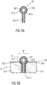
- Figures 3B-3C show schematically different exemplary embodiments of the invention with a seat cover 20 with a piping 10.
- the seat cover 20 comprises several cover parts 20.1, 20.2.
- the cover parts 20.1, 20.2 are fixed to a support 3 of a seat 5 (see Figure 4 ) attached, for example laminated.
- the Cover parts 20.1, 20.2 are applied in the form of laminations to the carrier 3 or its carrier parts 3.1, 3.2.
- the piping 10 is provided in the transition area B of at least two interconnected cover parts 20.1, 20.2.
- the welt 10 is thus integrated into the seat cover 20.
- the piping 10 is covered with a Velcro material 10.4 that protrudes outward from the surface of the seat cover 20, in particular a lamination.
- the welt 10 is completely encased by Velcro material 10.4, also in the area of the welt flaps 10.2.1. In this way, the welt 10 can easily be attached between the two cover parts 20.1, 20.2.
- the welt flaps 10.2.1 are otherwise attached to the seat cover 20, for example sewn, glued, welded.
- the cover material 10.2 can be omitted and the Velcro material 10.4 directly encases the welt core 10.1 and has a receptacle 10.3 for the welt core 10.1, as in FIG Figure 3E shown.
- a core flag 10.1.1 is used for fastening and is formed by the Velcro material 10.4.
- Figure 3D shows an embodiment of a welt 10 as shown in FIG Figure 3C is used.
- Figure 4 schematically shows a top view of a lower seat cover 20 for a seat part 4 of a seat 5 with an enlarged view of a transition area B between adjacent cover parts 20.1, 20.2, 20.4.
- the lower seat cover 20 has several cover parts 20.1 to 20.6.
- the welt 10 is provided in the transition area B between at least two adjacent cover parts 20.1 and 20.2, 20.2 and 20.3, 20.2 and 20.5 and / or between 20.2 and 20.4, the welt 10 is provided.
- the welt 10 can only be arranged in sections between the cover parts 20.1 to 20.6.
- the piping 10 can extend over the entire length in the transition area B of two adjacent cover parts 20.1 to 20.6.
- the welt 10 is arranged between at least two of the cover parts 20.1 to 20.6 in such a way, as is exemplified in FIG Figure 3B or 3C it is shown that the welt core 10.1 protrudes from the seat cover 20 on the surface side, for example in the form of a bead.
- at least the welt core 10.1 encased with at least the Velcro material 10.4 protrudes from this seam N in the transition area B, in particular at least in areas along a seam N between two interconnected cover parts 20.1 to 20.6.
- the welt core 10.1 protrudes from the seat cover 20 in the transition area B in the manner of a head protruding from the seam N, the welt core 10.1 forms a protruding bead so that a part to be attached to the seat cover 20, for example another seat cover 6, is simple and secure can adhere to the Velcro material 10.4.
- the seat cover 20 shown is a lower seat cover for a seat surface or a seat part 4 of the seat 5.
- an upper seat cover 6, which is shown in FIG Figure 5 is shown, are releasably attached.
- the upper seat cover 6 can be releasably attached to the lower seat cover 20.
- the upper seat cover 6 is provided with a holding material 7, in particular a fleece material.
- the two seat covers 6, 20 are via a Velcro connection between the Velcro material 10.4 of the welt 10 in the lower seat cover 20 and the Retaining material 7 of the upper seat cover 6 can be releasably connected to one another at least in regions along the seam N.
- the Velcro material 10.4 and the holding material 7 are arranged on opposite points of the seat covers 6, 20.
- the Velcro material 10.4 of the welt 10 and the holding material 7 of the upper seat cover 6 come into contact with one another and engage in one another in the connected state.
- the two seat covers 6, 20 can be separated from one another.
- Both seat covers 20 and 6 are designed to correspond to one another, for example, and have a corresponding number of cover parts 20.1 to 20.6 or 6.1 to 6.6.
- the removable upper seat cover 6 has the retaining material 7.
- the lower seat cover 20 has the piping 10 with the Velcro material 10.4 facing outward in this seam area.
- the piping 10 of the lower seat cover 20 is designed as a fastening and / or edge reinforcement piping.
- a welt 10, designed as a fastening welt, in particular so-called Velcro welt, for fastening the upper seat cover 6 to the seat 5, in particular to its lower seat cover 20, enables a tidy and comfortable impression. This results in a visually improved, in particular wrinkle-free seat cover 20, 6 with a detachable fastening at the same time.
Landscapes
- Engineering & Computer Science (AREA)
- Aviation & Aerospace Engineering (AREA)
- Transportation (AREA)
- Mechanical Engineering (AREA)
- Seats For Vehicles (AREA)
Description
- Die Erfindung betrifft einen Sitz, insbesondere einen Fahrzeugsitz.
- Üblicherweise ist ein Sitz, wie beispielsweise ein Fahrzeugsitz, mit einem Sitzbezug versehen. Darüber hinaus ist es bekannt, den Sitzbezug lösbar am Sitz zu befestigen, um den Sitzbezug beispielsweise zu entfernen oder auszutauschen. Hierzu ist es beispielsweise bekannt, den Sitzbezug und korrespondierend den Sitz oberflächenseitig mit Befestigungsmitteln, wie beispielsweise einem Klettband und gegenüberliegend einem Flauschband, zu versehen.
- Beispielsweise ist es aus der
FR 2 781 733 B1 - Aus der
EP 0 988 179 B1 ist ein Keder mit einer lichtleitenden Seele bekannt, der zur Befestigung von einer Folie umhüllt ist, deren Enden eine Nähfahne ausbilden. - Des Weiteren sind aus
FR 3 010 012 A1 US 2012/291 237 A1 ,US 5 005 242 A ,EP 2 979 569 A1 undEP 2 422 638 A1 Halteelemente zur Befestigung eines Bezugs an einem Sitzpolster bekannt. - Der Erfindung liegt die Aufgabe zu Grunde, einen Sitz mit einem Sitzbezug anzugeben.
- Die Aufgabe wird erfindungsgemäß mit einem Sitz gelöst, welcher die in Anspruch 1 angegebenen Merkmalen aufweist.
- Ein erfindungsgemäßer Sitz, insbesondere Fahrzeugsitz, umfasst ein Sitzpolster, einen am Sitzpolster befestigten unteren Sitzbezug und einen oberen Sitzbezug, welcher auf dem unteren Sitzbezug lösbar befestigbar ist. Dabei ist einer der Sitzbezüge mit zumindest einem Keder versehen, welcher eine Kederseele umfasst, die von einem Befestigungsmaterial umgeben ist, wobei der andere Sitzbezug mit einem Haltematerial versehen ist, in welches das Befestigungsmaterial des Keders im verbundenen Zustand haltend eingreift.
- Durch die Wahl eines bestimmten Sitzbezuges, insbesondere dessen Material, kann hierbei ein individueller Sitz geschaffen werden. Insbesondere können hierdurch unterschiedlich dekorative Sitze oder Sitze mit unterschiedlichen Sitzeigenschaften mit Sitzheizung und/oder -lüftung und/oder mit Raumklimazonen geschaffen werden.
- Gemäß einer Ausgestaltung der Erfindung ist die Kederseele von dem Befestigungsmaterial ummantelt. Das Befestigungsmaterial ist beispielsweise als ein Klettmaterial ausgebildet.
- Der Keder ist hierbei als ein Befestigungs- und/oder Randverstärkungskeder ausgebildet und ermöglicht durch Einbringung in einen Sitzbezug gegenüber herkömmlich aufgebrachten Verbindungsmitteln, wie z. B. aufgeklebten Klettbändern, einen optisch anmutenden, insbesondere glatten oder faltenfreien Sitzbezug.
- Gemäß einer Ausgestaltung der Erfindung ist das Klettmaterial ein Hakenmaterial, insbesondere eine Haken-, Pilzkopf- oder Ösen-Band/- Ware. Alternativ dazu kann das Klettmaterial auch als ein Flauschmaterial ausgebildet sein.
- Eine Befestigung des Befestigungsmaterials an der Kederseele kann mittels Stoffschluss erfolgen. Beispielsweise ist das Befestigungsmaterial mit der Kederseele verklebt oder verschweißt. Das Befestigungsmaterial kann dabei auch selbstklebend ausgebildet sein, beispielsweise mittels einer Haftklebstoffbeschichtung auf einer der Kederseele zugewandten Seite, wobei eine Scherkraft der Haftklebstoffbeschichtung größer ist als eine Scherkraft der lösbaren Verbindung zwischen dem Befestigungsmaterial und einem am Sitzbezug angeordneten Haftmaterial.
- Gemäß einer weiteren Ausgestaltung der Erfindung ist zwischen dem Befestigungsmaterial und der Kederseele ein Bezugsmaterial angeordnet. Das Bezugsmaterial dient einerseits einer Kaschierung der Kederseele. Andererseits dient das Bezugsmaterial einer Befestigung des Keders beispielsweise an einem Sitzteil, insbesondere einer Sitzfläche oder an einem unteren Sitzbezug. Das Bezugsmaterial ummantelt dabei die Kederseele und wird an dessen Enden unter Ausbildung einer Kederfahne verklebt oder vernäht. Das Befestigungsmaterial ist hierbei mit dem Bezugsmaterial verbunden und ummantelt das die Kederseele ummantelnde Bezugsmaterial. Das Befestigungsmaterial kann dabei mit dem Bezugsmaterial stoffschlüssig verbunden sein. Insbesondere ist das Befestigungsmaterial mit dem Bezugsmaterial verklebt oder verschweißt. Alternativ kann das Befestigungsmaterial auch mit dem Bezugsmaterial vernäht sein.
- Alternativ ist es möglich, dass das Befestigungsmaterial die Kederseele unmittelbar ummantelt und an dessen Enden eine Kederfahne ausbildet.
- Vorzugsweise ist die Kederseele aus einem elastischen Material, insbesondere aus Kunststoff oder Gummi, gebildet. Dies ermöglicht einen angenehmen Sitzkomfort für eine auf dem Sitzbezug sitzende Person. Des Weiteren ist das Bezugsmaterial aus Kunststoff, z. B. Polypropylen, oder einem Naturmaterial, gebildet. Das Bezugsmaterial ist insbesondere fester als die Kederseele ausgebildet.
- Gemäß einer Ausgestaltung der Erfindung ist für den Sitzbezug eine Mehrzahl von Bezugsteilen vorgesehen, wobei im Bereich von mindestens zwei miteinander verbundenen Bezugsteilen wenigstens ein Keder vorgesehen ist.
- Mittels Einbringen des Keders wird ein optisch anmutender, insbesondere glatter oder faltenfreier, Sitzbezug, ermöglicht, welcher auf einfache Art und Weise mit dem Sitz verbunden und somit ausgetauscht werden kann.
- Gemäß einer Ausgestaltung des Sitzes ist das Haltematerial ein Flauschmaterial, welches mit einem als Hakenmaterial ausgebildeten Klettmaterials eine lösbare Verbindung herstellt. Alternativ kann das Haltematerial auch ein Hakenmaterial sein, wobei das Befestigungsmaterial ein Schlaufenmaterial oder Flauschmaterial ist. Das Haltematerial kann mit dem Sitzbezug stoffschlüssig verbunden sein. Beispielsweise ist das Haltematerial mit Sitzbezug verklebt oder verschweißt. Alternativ dazu kann das Haltematerial auch mit dem Sitzbezug vernäht sein.
- Ausführungsbeispiele der Erfindung werden anhand von Zeichnungen näher erläutert. Dabei zeigen:
- Figur 1
- schematisch ein Ausführungsbeispiel für einen Keder gemäß dem Stand der Technik,
- Figur 2
- schematisch ein Ausführungsbeispiel für einen lösbaren Sitzbezug mit einem oberflächenseitig aufgebrachten Verbindungsmittel gemäß dem Stand der Technik,
- Figur 3A, 3D
- schematisch ein Ausführungsbeispiel für einen Keder,
- Figuren 3B-3C
- schematisch verschiedene Ausführungsbeispiele für einen Sitzbezug mit einem Keder,
- Figur 4
- schematisch eine Draufsicht auf einen unteren Sitzbezug mit einem Keder, und
- Figur 5
- schematisch ein Ausführungsbeispiel für einen oberen, abnehmbaren oder lösbaren Sitzbezug.
- Einander entsprechende Teile sind in allen Figuren mit den gleichen Bezugszeichen versehen.
-
Figur 1 zeigt schematisch im Schnitt ein Ausführungsbeispiel für einen Keder 1 gemäß dem Stand der Technik. Keder 1 werden im Automobilbereich eingesetzt. Der Keder 1 dient im Allgemeinen zur Abdeckung von beispielsweise sichtbaren Fugen zwischen zwei Teilen, wie zum Beispiel zwischen Sitzbezugsteilen oder Teilen eines Verkleidungsteils. Auch wird der Keder 1 im Übergangsbereich von Teilen eingesetzt, um beispielsweise einen fließenden Übergang ohne den störenden Eindruck von Fugen zu ermöglichen. Mittels des Keder 1 wird somit das ästhetische Erscheinungsbild einer Komponente, wie die eines Sitzes oder Sitzbezuges verschönert. - Der Keder 1 umfasst eine Kederseele 1.1 und ein diese umgebendes Bezugsmaterial 1.2 auf. Das Bezugsmaterial 1.2 umgibt die Kederseele 1.1 vollständig und steht in Form von Kederfahnen 1.2.1 ab. Die Kederseele 1.1 ist beispielsweise aus einem elastischen Material, beispielsweise aus Kunststoff oder Kautschuk. Das Bezugsmaterial 1.2 und die Kederfahnen 1.2.1 sind einteilig ausgebildet. Beispielsweise sind das Bezugsmaterial 1.2 und die Kederfahnen 1.2.1 aus einem Dekormaterial, insbesondere aus einem Kunststoff oder einem Naturmaterial, beispielsweise aus Polypropylen, Kunststoff- oder Echtleder oder einem anderen Textil, gebildet.
- Das Bezugsmaterial 1.2 ummantelt oder umschlingt im gezeigten Ausführungsbeispiel die Kederseele 1.1. Die freien Enden des Bezugsmaterials 1.2 stehen von der umschlungenen Kederseele 1.1 in Form der Kederfahnen 1.2.1 ab.
- Der Keder 1 kann einstückig, als ein in einem Extrusions- oder Spritzgießverfahren hergestelltes Element sein. Alternativ können das Bezugsmaterial 1.2 mit den Kederfahnen 1.2.1 und die Kederseele 1.1 separat gefertigt sein, wobei die Kederseele 1.1 in einer Kederaufnahme 1.3 des Bezugsmaterials 1.2 einführbar und dort anordenbar ist.
-
Figur 2 zeigt schematisch ein Ausführungsbeispiel für einen lösbaren Sitzbezug 2 mit einem oberflächenseitig aufgebrachten Verbindungsmittel V gemäß dem Stand der Technik. Der Sitzbezug 2 umfasst mehrere Bezugsteile 2.1 bis 2.3. Das Verbindungsmittel V ist dabei im Übergangsbereich B zwischen zwei angrenzenden Bezugsteilen 2.1 bis 2.3 am Sitzbezug 2 angeordnet. Im Ausführungsbeispiel ist das Verbindungsmittel V als ein aufgeklebtes Klettband ausgebildet. -
Figur 3A zeigt schematisch ein Ausführungsbeispiel der Erfindung für einen Keder 10. Der Keder 10 weist eine Kederseele 10.1 auf, die von einem Bezugsmaterial 10.2 umgeben ist. Das Bezugsmaterial 10.2 ist wiederum von einem Befestigungsmaterial 10.4, insbesondere einem Klettmaterial umgeben, insbesondere ummantelt. Zur besseren Übersicht wird nachfolgend das Befestigungsmaterial 10.4 als Klettmaterial 10.4 bezeichnet. - Die Kederseele 10.1 ist aus einem elastischen Material, insbesondere aus Kunststoff oder Gummi. Das Bezugsmaterial 10.2 ist aus Kunststoff, zum Beispiel Polypropylen, oder einem Naturmaterial, wie zum Beispiel Leder oder Stoff. Das Bezugsmaterial 10.2 ist insbesondere fester als die Kederseele 10.1 ausgebildet.
- Je nach Art und Form des Klettmaterials 10.4 kann das Bezugsmaterial 10.2 entfallen und das Klettmaterial 10.4 direkt die Kederseele 10.1 ummanteln und eine Aufnahme 10.3 für die Kederseele 10.1 aufweisen. Das Klettmaterial 10.4 kann als ein Klettband oder Klettware (= Breitware) ausgebildet sein. Es kann ein- oder beidseitig selbstklebend ausgebildet sein. Bevorzugt ist das auf den Keder 10 aufgebrachte Klettmaterial 10.4 ein Hakenmaterial, insbesondere ein Haken-, Pilzkopf- oder Ösen-Band/-Ware. Alternativ kann auf den Keder 10 als Klettmaterial 10.4 ein Haft- oder Flauschmaterial, insbesondere ein Haft- oder Flausch-Band oder eine Haft- oder Flausch-Ware, aufgebracht sein. Das Klettmaterial 10.4 ist stoffschlüssig am Keder 10 befestigt, insbesondere geklebt oder geschweißt.
-
Figuren 3B-3C zeigen schematisch verschiedene Ausführungsbeispiele der Erfindung mit einem Sitzbezug 20 mit einem Keder 10. - Der Sitzbezug 20 umfasst mehrere Bezugsteile 20.1, 20.2. Die Bezugsteile 20.1, 20.2 sind fest an einem Träger 3 eines Sitzes 5 (siehe
Figur 4 ) befestigt, beispielsweise kaschiert. Mit anderen Worten: Die Bezugsteile 20.1, 20.2 sind in Form von Kaschierungen auf den Träger 3 oder dessen Trägerteile 3.1, 3.2 aufgebracht. - Im Übergangsbereich B von mindestens zwei miteinander verbundenen Bezugsteilen 20.1, 20.2 ist der Keder 10 vorgesehen. Somit ist der Keder 10 in den Sitzbezug 20 integriert. Der Keder 10 ist mit einem Klettmaterial 10.4 ummantelt, das von der Oberfläche des Sitzbezuges 20, insbesondere einer Kaschierung, nach außen ragt.
- In
Figur 3B ist der Keder 10 vollständig vom Klettmaterial 10.4 ummantelt, auch im Bereich der Kederfahnen 10.2.1. Hierdurch kann der Keder 10 einfach zwischen den beiden Bezugsteilen 20.1, 20.2 befestigt werden. - Alternativ kann der Keder 10, wie in
Figur 3C gezeigt, nur im äußeren Bereich des Keders 10, d. h. nur im die Kederseele 10.1 umgebenden äußeren Bereich, mit Klettmaterial 10.4 versehen sein. In diesem Fall werden die Kederfahnen 10.2.1 anderweitig am Sitzbezug 20 befestigt, beispielsweise genäht, geklebt, geschweißt. Je nach Art und Form des Klettmaterials 10.4 kann das Bezugsmaterial 10.2 entfallen und das Klettmaterial 10.4 direkt die Kederseele 10.1 ummanteln und eine Aufnahme 10.3 für die Kederseele 10.1 aufweisen, wie inFigur 3E gezeigt. Dabei dient eine Seelenfahne 10.1.1 zur Befestigung und ist durch das Klettmaterial 10.4 gebildet. -
Figur 3D zeigt eine Ausführungsform eines Keders 10, wie sie inFigur 3C verwendet wird. -
Figur 4 zeigt schematisch eine Draufsicht auf einen unteren Sitzbezug 20 für ein Sitzteil 4 eines Sitzes 5 mit einer vergrößerten Darstellung eines Übergangsbereiches B zwischen angrenzenden Bezugsteilen 20.1, 20.2, 20.4. Der untere Sitzbezug 20 weist mehrere Bezugsteile 20.1 bis 20.6 auf. Im Übergangsbereich B zwischen zumindest zwei angrenzenden Bezugsteilen 20.1 und 20.2, 20.2 und 20.3, 20.2 und 20.5 und/oder zwischen 20.2 und 20.4 ist der Keder 10 vorgesehen. Dabei kann der Keder 10 nur abschnittsweise zwischen den Bezugsteilen 20.1 bis 20.6 angeordnet sein. Alternativ oder zusätzlich kann sich der Keder 10 über die gesamte Länge im Übergangsbereich B zweier angrenzender Bezugsteile 20.1 bis 20.6 erstrecken. Dabei ist der Keder 10 zwischen mindestens zwei der Bezugsteile 20.1 bis 20.6 derart angeordnet, wie dies beispielhaft in derFigur 3B oder3C gezeigt ist, dass die Kederseele 10.1 oberflächenseitig beispielsweise wulstförmig vom Sitzbezug 20 absteht. Mit anderen Worten: Zumindest die mit zumindest dem Klettmaterial 10.4 ummantelte Kederseele 10.1 steht im Übergangsbereich B, insbesondere zumindest bereichsweise entlang einer Naht N zwischen zwei miteinander verbundenen Bezugsteilen 20.1 bis 20.6 von dieser Naht N ab. Da nur die Kederseele 10.1 in Art eines aus der Naht N herausragenden Kopfes im Übergangsbereich B vom Sitzbezug 20 absteht, bildet die Kederseele 10.1 einen abstehenden Wulst, so dass ein auf dem Sitzbezug 20 zu befestigendes Teil, zum Beispiel eine anderer Sitzbezug 6 einfach und sicher am Klettmaterial 10.4 anhaften kann. - Der in
Figur 4 dargestellte Sitzbezug 20 ist ein unterer Sitzbezug für eine Sitzfläche oder ein Sitzteil 4 des Sitzes 5. An diesem unteren Sitzbezug 20, insbesondere einem Sitzpolster, kann ein oberer Sitzbezug 6, der inFigur 5 dargestellt ist, lösbar befestigt werden. Mit anderen Worten: Der obere Sitzbezug 6 ist auf dem unteren Sitzbezug 20 lösbar befestigbar. - Zur lösbaren Befestigung des oberen Sitzbezugs 6 am unteren Sitzbezug 20 ist der obere Sitzbezug 6 mit einem Haltematerial 7, insbesondere einem Flauschmaterial, versehen. Somit sind die beiden Sitzbezüge 6, 20 über eine Klettverbindung zwischen dem Klettmaterial 10.4 des Keders 10 im unteren Sitzbezug 20 und dem Haltematerial 7 des oberen Sitzbezugs 6 zumindest bereichsweise entlang der Naht N miteinander lösbar verbindbar.
- Das Klettmaterial 10.4 und das Haltematerial 7 sind aneinander gegenüberliegenden Stellen der Sitzbezüge 6, 20 angeordnet. Somit tritt das Klettmaterial 10.4 des Keders 10 und das Haltematerial 7 des oberen Sitzbezuges 6 in Kontakt miteinander und greifen im verbundenen Zustand ineinander ein. Durch Auseinanderziehen, insbesondere Abziehen des oberen Sitzbezugs 6 vom unteren am Sitzteil 4 fest gehaltenen Sitzbezuges 20 sind beide Sitzbezüge 6, 20 voneinander trennbar.
- Beide Sitzbezüge 20 und 6 sind beispielsweise korrespondierend zueinander ausgebildet und weisen eine korrespondierende Anzahl von Bezugsteilen 20.1 bis 20.6 bzw. 6.1 bis 6.6 auf.
- Im Übergangsbereich B, insbesondere im Nahtbereich, zwischen angrenzenden Bezugsteilen 6.1 bis 6.6 weist der abnehmbare obere Sitzbezug 6 das Haltematerial 7 auf. Analog dazu weist der untere Sitzbezug 20 in diesem Nahtbereich den Keder 10 mit dem nach außen weisenden Klettmaterial 10.4 auf.
- Somit ist der Keder 10 des unteren Sitzbezugs 20 als ein Befestigungs- und/oder Randverstärkungskeder ausgebildet. Ein solcher als Befestigungskeder, insbesondere sogenannter Klettkeder, ausgebildeter Keder 10 zur Befestigung des oberen Sitzbezugs 6 an dem Sitz 5, insbesondere an dessen unterem Sitzbezug 20, ermöglicht einen aufgeräumten und komfortablen Eindruck. Hierdurch ist ein optisch verbesserter, insbesondere faltenfreier Sitzbezug 20, 6 mit gleichzeitig lösbarer Befestigung gegeben.
-
- 1,10
- Keder
- 1.1, 10.1
- Kederseele
- 10.1.1.
- Seelenfahne
- 1.2, 10.2
- Bezugsmaterial
- 1.2.1, 10.2.1
- Kederfahne
- 1.3, 10.3
- Kederaufnahme
- 10.4
- Befestigungsmaterial, Klettmaterial
- 2, 20
- (unterer) Sitzbezug
- 2.1-2.3, 20.1-20.6
- Bezugsteile
- 3
- Träger
- 3.1, 3.2
- Trägerteile
- 4
- Sitzteil
- 5
- Sitz
- 6
- (oberer) Sitzbezug
- 6.1 bis 6.6
- Bezugsteile
- 7
- Haltematerial
- V
- Verbindungsmittel
- B
- Übergangsbereich
- N
- Naht
Claims (11)
- Sitz (5), insbesondere Fahrzeugsitz, umfassend- ein Sitzpolster,- einen am Sitzpolster befestigten unteren Sitzbezug (20),- einen oberen Sitzbezug (6), welcher auf dem unteren Sitzbezug (20) lösbar befestigbar ist,- wobei einer der Sitzbezüge (6, 20) mit zumindest einem Keder (10) versehen ist- wobei der Keder (10) eine Kederseele (10.1) umfasst, die von einem Befestigungsmaterial (10.4) umgeben ist, und- wobei der andere Sitzbezug (6, 20) mit einem Haltematerial (7) versehen ist, in welches das Befestigungsmaterial (10.4) des Keders (10) im verbundenen Zustand haltend eingreift.
- Sitz (5) nach Anspruch 1, wobei die Kederseele (10.1) von dem Befestigungsmaterial (10.4) ummantelt ist.
- Sitz (5) nach Anspruch 1 oder 2, wobei das Befestigungsmaterial (10.4) als ein Klettmaterial (10.4) ausgebildet ist.
- Sitz (5) nach Anspruch 3, wobei das Klettmaterial (10.4) ein Hakenmaterial ist.
- Sitz (5) nach einem der vorhergehenden Ansprüche, wobei das Befestigungsmaterial (10.4) stoffschlüssig mit der Kederseele (10.1) verbunden ist.
- Sitz (5) nach einem der Ansprüche 1 bis 4, wobei zwischen dem Befestigungsmaterial (10.4) und der Kederseele (10.1) ein Bezugsmaterial (10.2) angeordnet ist.
- Sitz (5) nach einem der vorhergehenden Ansprüche, wobei die Kederseele (10.1) aus einem elastischen Material, insbesondere aus Kunststoff oder Gummi, gebildet ist.
- Sitz (5) nach Anspruch 6 oder 7, wobei das Bezugsmaterial (10.2) aus Kunststoff, Leder oder einem Gewebe gebildet ist.
- Sitz (5) nach einem der vorhergehenden Ansprüche, wobei das Befestigungsmaterial (10.4) aus Kunststoff gebildet ist.
- Sitz (5) nach einem der vorhergehenden Ansprüche, wobei- der Sitzbezug (6, 20) eine Mehrzahl von Bezugsteilen (6.1 bis 6.6) aufweist, und- im Bereich von mindestens zwei miteinander verbundenen Bezugsteilen (6.1 bis 6.6) wenigstens ein Keder (10) vorgesehen ist.
- Sitz (5) nach einem der vorhergehenden Ansprüche, wobei das Haltematerial (7) ein Flauschmaterial ist.
Applications Claiming Priority (3)
| Application Number | Priority Date | Filing Date | Title |
|---|---|---|---|
| DE102016209034 | 2016-05-24 | ||
| DE102016210873.5A DE102016210873A1 (de) | 2016-05-24 | 2016-06-17 | Keder, Sitzbezug und Sitz mit einem Sitzbezug |
| PCT/EP2017/062419 WO2017202850A1 (de) | 2016-05-24 | 2017-05-23 | Keder, sitzbezug und sitz mit einem sitzbezug |
Publications (2)
| Publication Number | Publication Date |
|---|---|
| EP3463972A1 EP3463972A1 (de) | 2019-04-10 |
| EP3463972B1 true EP3463972B1 (de) | 2020-09-30 |
Family
ID=60269444
Family Applications (1)
| Application Number | Title | Priority Date | Filing Date |
|---|---|---|---|
| EP17725257.4A Active EP3463972B1 (de) | 2016-05-24 | 2017-05-23 | Keder, sitzbezug und sitz mit einem sitzbezug |
Country Status (5)
| Country | Link |
|---|---|
| US (1) | US10960797B2 (de) |
| EP (1) | EP3463972B1 (de) |
| CN (1) | CN109153344B (de) |
| DE (1) | DE102016210873A1 (de) |
| WO (1) | WO2017202850A1 (de) |
Families Citing this family (3)
| Publication number | Priority date | Publication date | Assignee | Title |
|---|---|---|---|---|
| WO2021142898A1 (zh) * | 2020-01-19 | 2021-07-22 | 延锋安道拓座椅有限公司 | 一种提升座椅面套外观的缝纫结构 |
| DE102020119362B4 (de) | 2020-07-22 | 2025-02-06 | Audi Aktiengesellschaft | Sitzauflage für Kinder und eine Sitzanordnung und ein Fahrzeug mit einer Sitzauflage |
| DE102022130558A1 (de) | 2022-11-18 | 2024-05-23 | Bayerische Motoren Werke Aktiengesellschaft | Keder und Verfahren zur Herstellung eines Keders |
Family Cites Families (54)
| Publication number | Priority date | Publication date | Assignee | Title |
|---|---|---|---|---|
| US2290007A (en) * | 1940-06-07 | 1942-07-14 | Percy W Valentine | Welt seam |
| US2440138A (en) * | 1945-11-13 | 1948-04-20 | Benenfeld Peter | Reinforced corner seam for utility bags |
| US2659421A (en) | 1950-11-21 | 1953-11-17 | Wass Yvonne | Upholstery covering |
| US2770816A (en) | 1955-09-06 | 1956-11-20 | Reisner Michael | Cushions and method of making the same |
| FR1593125A (de) | 1968-11-07 | 1970-05-25 | ||
| FR1592046A (de) | 1968-11-18 | 1970-05-04 | ||
| DE7017769U (de) | 1969-05-14 | 1970-08-06 | Peugeot | Sitzbezug. |
| DE7332499U (de) * | 1973-09-07 | 1973-12-20 | Neuweiler G | Schonbezug fuer kraftfahrzeugsitze |
| US4095543A (en) | 1977-02-28 | 1978-06-20 | Maynard Plastics, Inc. | Dual extrusion welt |
| DE8136861U1 (de) * | 1981-12-17 | 1982-04-22 | Deuter Industriewerke Ag, 8900 Augsburg | Ein aus zwei teilen bestehender koffer bzw. tasche |
| DE3422769C2 (de) | 1984-06-20 | 1994-09-15 | Mestri Gmbh | Keder |
| DE3620695C2 (de) | 1986-06-20 | 1994-08-25 | Mestri Gmbh | Keder für Nähte an Polsterwaren |
| JPS633263U (de) | 1986-06-26 | 1988-01-11 | ||
| US5005242A (en) * | 1990-02-06 | 1991-04-09 | Velcro Industries B.V. | Foamed seat cushion |
| US6048026A (en) * | 1990-05-24 | 2000-04-11 | Barnett; Karl Frederick | Adhesive secured seat cover and method |
| AT399488B (de) * | 1991-04-22 | 1995-05-26 | Greiner & Soehne C A | Sitzpolster, insbesondere flugzeugsitz |
| US5236243A (en) * | 1992-03-30 | 1993-08-17 | General Motors Corporation | Serge thread loop fastener for trim cover |
| JP3255384B2 (ja) | 1993-12-27 | 2002-02-12 | 株式会社クラレ | モールドイン成形体、成形方法、成形用係止部材 |
| AT726U1 (de) | 1995-06-07 | 1996-04-25 | Eybl Krems Textilwerke Ag | Schonbezug für sitze von autos und anderen verkehrsmitteln |
| US6206467B1 (en) * | 1996-11-20 | 2001-03-27 | F.S. Fehrer Gmbh & Co. Kg | Upholstered element fastened to a cover by means of a hook and loop strip |
| DE19724486A1 (de) | 1997-06-10 | 1998-12-17 | Draexlmaier Lisa Gmbh | Befestigung eines Lichtwellenleiters zur Konturbeleuchtung |
| FR2781733B1 (fr) | 1998-07-29 | 2000-09-29 | Faure Bertrand Equipements Sa | Siege de vehicule automobile comportant une coiffe de garnissage amovible et coiffe pour un tel siege |
| DE19845661B4 (de) * | 1998-10-05 | 2004-04-29 | Daimlerchrysler Ag | Schutzverpackung aus Kunststoffolie für einen Fahrzeugsitz sowie Verfahren zum Verpacken desselben |
| US6588838B1 (en) * | 2000-03-23 | 2003-07-08 | Lear Corporation | Reinforced seat cover |
| US6443525B1 (en) * | 2000-05-22 | 2002-09-03 | Johnson Controls Technology Company | Vehicle seat assembly and fastening device |
| US6345866B1 (en) * | 2000-08-03 | 2002-02-12 | Usa Products | Adjustable seat covers for high or low back seats |
| JP2004242909A (ja) * | 2003-02-14 | 2004-09-02 | Kuraray Co Ltd | モールドイン成形用係止部材および係止部材付き樹脂成形体の製造方法 |
| JP4156449B2 (ja) * | 2003-06-12 | 2008-09-24 | 株式会社クラレ | シートの係止連結部材、該部材を有するシート、該部材を用いた成形体及びその製造方法 |
| JP4674526B2 (ja) | 2005-10-18 | 2011-04-20 | トヨタ紡織株式会社 | 車両用シート |
| FR2900607B1 (fr) | 2006-05-04 | 2008-07-25 | Faurecia Sieges Automobile | Siege de vehicule automobile comportant une coiffe de garnissage amovible, et coiffe pour un tel siege |
| US7488036B2 (en) | 2006-09-12 | 2009-02-10 | Nissan Technical Center North America, Inc. | Seat cover for automotive vehicle seat |
| DE102007011575B4 (de) | 2007-03-08 | 2010-07-15 | diamona Hermann Koch GmbH & Co. KG Fabrik für Wohn- und Schlafkomfort | Decke und Verfahren zur Herstellung einer Decke |
| FR2913641B1 (fr) * | 2007-03-12 | 2009-06-12 | Faurecia Sieges Automobile | Organe d'accrochage d'une coiffe souple d'habillage d'une matelassure |
| MY151916A (en) * | 2009-03-18 | 2014-07-31 | Seatcoverpro Sdn Bhd | Vehicle seat cover |
| CN102368925A (zh) | 2009-03-27 | 2012-03-07 | 可乐丽粘扣带股份有限公司 | 覆盖件的卡止连结部件及覆盖衬垫成形体的制造方法 |
| JP5234684B2 (ja) * | 2009-04-30 | 2013-07-10 | Ykk株式会社 | 止着部材 |
| FR2955234B1 (fr) | 2010-01-20 | 2012-04-27 | Aplix Sa | Assemblage d'un surmoule a crochets et d'un moule comportant un piedestal |
| FR2955233B1 (fr) * | 2010-01-20 | 2012-04-27 | Aplix Sa | Assemblage d'un objet moule comportant une pluralite d'elements a crochets surmoules et d'un recouvrement |
| US8662583B2 (en) * | 2011-01-24 | 2014-03-04 | Lear Corporation | Vehicle seat trim attachment |
| JP2012223262A (ja) * | 2011-04-18 | 2012-11-15 | Toyota Boshoku Corp | 車両用シート |
| CN202243095U (zh) * | 2011-10-09 | 2012-05-30 | 王典超 | 能够自适应大小并带有可更换面料的座椅套 |
| CN105050445A (zh) * | 2013-03-27 | 2015-11-11 | 可乐丽粘贴扣带株式会社 | 在两面具有倾斜主茎的片材以及使用该片材的座椅 |
| DE102013008293B4 (de) * | 2013-05-15 | 2017-07-13 | Adient Luxembourg Holding S.à.r.l. | Verfahren und Vorrichtung zum Aufbringen von mindestens einem Zierstreifen auf einem Sitzbezug |
| JP6029552B2 (ja) * | 2013-08-13 | 2016-11-24 | 株式会社タチエス | 車両用シート |
| JP6173837B2 (ja) * | 2013-08-29 | 2017-08-02 | トヨタ紡織株式会社 | 玉縁 |
| FR3010012B1 (fr) | 2013-09-03 | 2015-09-18 | Aplix Sa | Dispositif de retenue a crochets |
| US9199564B2 (en) * | 2013-12-12 | 2015-12-01 | Lear Corporation | Seat assembly having a trim cover assembly |
| KR101808976B1 (ko) * | 2014-03-13 | 2017-12-13 | 와이케이케이 가부시끼가이샤 | 성형면 파스너, 쿠션체, 및 쿠션체의 제조 방법 |
| FR3022504B1 (fr) | 2014-06-20 | 2016-07-29 | Faurecia Sieges Automobile | Jonc pour coiffe de vehicule automobile |
| JP2016077681A (ja) * | 2014-10-20 | 2016-05-16 | 株式会社タチエス | 面ファスナー部材およびそれを用いたシート |
| JP6436739B2 (ja) | 2014-11-20 | 2018-12-12 | ダイハツ工業株式会社 | シートカバー |
| JP6307419B2 (ja) | 2014-11-26 | 2018-04-04 | 株式会社タチエス | シート |
| JP2016097948A (ja) * | 2014-11-26 | 2016-05-30 | 株式会社タチエス | シート |
| JP3199332U (ja) * | 2015-03-31 | 2015-08-20 | Ykk株式会社 | 表皮材固定構造及び表皮材剥がし治具 |
-
2016
- 2016-06-17 DE DE102016210873.5A patent/DE102016210873A1/de active Pending
-
2017
- 2017-05-23 CN CN201780031984.1A patent/CN109153344B/zh active Active
- 2017-05-23 WO PCT/EP2017/062419 patent/WO2017202850A1/de not_active Ceased
- 2017-05-23 US US16/303,944 patent/US10960797B2/en active Active
- 2017-05-23 EP EP17725257.4A patent/EP3463972B1/de active Active
Non-Patent Citations (1)
| Title |
|---|
| None * |
Also Published As
| Publication number | Publication date |
|---|---|
| CN109153344A (zh) | 2019-01-04 |
| US10960797B2 (en) | 2021-03-30 |
| CN109153344B (zh) | 2022-06-03 |
| DE102016210873A1 (de) | 2017-11-30 |
| US20200254910A1 (en) | 2020-08-13 |
| WO2017202850A1 (de) | 2017-11-30 |
| EP3463972A1 (de) | 2019-04-10 |
Similar Documents
| Publication | Publication Date | Title |
|---|---|---|
| EP3126188B1 (de) | Verfahren zur herstellung eines mit einem bezug versehenen elementes und ein solches element | |
| DE112012005161T5 (de) | Nahtabstandshalter zur Verwendung bei Ziernähten von Fahrzeuginnenteilen | |
| EP3492320B2 (de) | Fixierhilfe zum einfachen fixieren von nähkleidern auf trägerteilen | |
| EP3498529B1 (de) | Schonbezug für einen kraftfahrzeugsitz | |
| DE102018201754A1 (de) | Keder für einen Sitzbezug | |
| WO2017202850A1 (de) | Keder, sitzbezug und sitz mit einem sitzbezug | |
| DE102006020306A1 (de) | Befestigungsvorrichtung zum Verbinden eines Polsterbezuges mit einem Polster | |
| DE10357583B3 (de) | Luftverteilungseinrichtung für eine Baueinheit im Fahrgastraum | |
| DE202007011983U1 (de) | Büstenhalter | |
| DE102010033885A1 (de) | Innenverkleidungsteil sowie Verfahren und Vorrichtung zum Herstellen des Innenverkleidungsteils | |
| DE102021119034A1 (de) | Bezug, Polsterelement und Verfahren zum Herstellen des Bezugs | |
| EP3494827B1 (de) | System aus einer abdeckfolie und einem haftverschlussteil | |
| WO2019149934A1 (de) | Vorrichtung und verfahren zur herstellung eines keders für einen sitzbezug | |
| DE102010024207A1 (de) | Rückenlehnen- oder Sitzteil für einen Fahrzeugsitz oder eine Fahrzeugsitzbank und Verfahren zu dessen Herstellung | |
| DE202009018800U1 (de) | Textiler Träger zur Stabilisierung von Bezügen und Verbund mit einem textilen Träger | |
| EP3792106B1 (de) | Sitzverkleidung, sowie verfahren zur herstellung einer sitzverkleidung | |
| DE102007062636B4 (de) | Fahrzeugsitz | |
| DE102009004321A1 (de) | Reißverschlusselement, Polsteranordnung und Fahrzeugsitz | |
| DE102017222213A1 (de) | Kraftfahrzeug-Innenausstattungsteil | |
| DE102008028507B3 (de) | Bezug | |
| DE202008017863U1 (de) | Befestigungselement | |
| DE102006012701B4 (de) | Ausstattungsteil für ein Kraftfahrzeug umfassend einen Polsterkörper und ein Bezugsmaterial, Bezugsmaterial und Verfahren | |
| DE102009012777A1 (de) | Fahrzeugsitz, insbesondere für ein Kraftfahrzeug | |
| EP3527427B1 (de) | Fixier- und/oder haltenetz für fahrzeuge | |
| DE3712607C2 (de) | Gepolstertes Ausstattungsteil |
Legal Events
| Date | Code | Title | Description |
|---|---|---|---|
| STAA | Information on the status of an ep patent application or granted ep patent |
Free format text: STATUS: UNKNOWN |
|
| STAA | Information on the status of an ep patent application or granted ep patent |
Free format text: STATUS: THE INTERNATIONAL PUBLICATION HAS BEEN MADE |
|
| PUAI | Public reference made under article 153(3) epc to a published international application that has entered the european phase |
Free format text: ORIGINAL CODE: 0009012 |
|
| STAA | Information on the status of an ep patent application or granted ep patent |
Free format text: STATUS: REQUEST FOR EXAMINATION WAS MADE |
|
| 17P | Request for examination filed |
Effective date: 20190102 |
|
| AK | Designated contracting states |
Kind code of ref document: A1 Designated state(s): AL AT BE BG CH CY CZ DE DK EE ES FI FR GB GR HR HU IE IS IT LI LT LU LV MC MK MT NL NO PL PT RO RS SE SI SK SM TR |
|
| AX | Request for extension of the european patent |
Extension state: BA ME |
|
| DAV | Request for validation of the european patent (deleted) | ||
| DAX | Request for extension of the european patent (deleted) | ||
| GRAP | Despatch of communication of intention to grant a patent |
Free format text: ORIGINAL CODE: EPIDOSNIGR1 |
|
| STAA | Information on the status of an ep patent application or granted ep patent |
Free format text: STATUS: GRANT OF PATENT IS INTENDED |
|
| INTG | Intention to grant announced |
Effective date: 20200424 |
|
| GRAS | Grant fee paid |
Free format text: ORIGINAL CODE: EPIDOSNIGR3 |
|
| GRAA | (expected) grant |
Free format text: ORIGINAL CODE: 0009210 |
|
| STAA | Information on the status of an ep patent application or granted ep patent |
Free format text: STATUS: THE PATENT HAS BEEN GRANTED |
|
| AK | Designated contracting states |
Kind code of ref document: B1 Designated state(s): AL AT BE BG CH CY CZ DE DK EE ES FI FR GB GR HR HU IE IS IT LI LT LU LV MC MK MT NL NO PL PT RO RS SE SI SK SM TR |
|
| REG | Reference to a national code |
Ref country code: CH Ref legal event code: EP Ref country code: GB Ref legal event code: FG4D Free format text: NOT ENGLISH |
|
| REG | Reference to a national code |
Ref country code: DE Ref legal event code: R096 Ref document number: 502017007522 Country of ref document: DE Ref country code: AT Ref legal event code: REF Ref document number: 1318462 Country of ref document: AT Kind code of ref document: T Effective date: 20201015 |
|
| REG | Reference to a national code |
Ref country code: IE Ref legal event code: FG4D Free format text: LANGUAGE OF EP DOCUMENT: GERMAN |
|
| PG25 | Lapsed in a contracting state [announced via postgrant information from national office to epo] |
Ref country code: GR Free format text: LAPSE BECAUSE OF FAILURE TO SUBMIT A TRANSLATION OF THE DESCRIPTION OR TO PAY THE FEE WITHIN THE PRESCRIBED TIME-LIMIT Effective date: 20201231 Ref country code: SE Free format text: LAPSE BECAUSE OF FAILURE TO SUBMIT A TRANSLATION OF THE DESCRIPTION OR TO PAY THE FEE WITHIN THE PRESCRIBED TIME-LIMIT Effective date: 20200930 Ref country code: BG Free format text: LAPSE BECAUSE OF FAILURE TO SUBMIT A TRANSLATION OF THE DESCRIPTION OR TO PAY THE FEE WITHIN THE PRESCRIBED TIME-LIMIT Effective date: 20201230 Ref country code: NO Free format text: LAPSE BECAUSE OF FAILURE TO SUBMIT A TRANSLATION OF THE DESCRIPTION OR TO PAY THE FEE WITHIN THE PRESCRIBED TIME-LIMIT Effective date: 20201230 Ref country code: FI Free format text: LAPSE BECAUSE OF FAILURE TO SUBMIT A TRANSLATION OF THE DESCRIPTION OR TO PAY THE FEE WITHIN THE PRESCRIBED TIME-LIMIT Effective date: 20200930 Ref country code: HR Free format text: LAPSE BECAUSE OF FAILURE TO SUBMIT A TRANSLATION OF THE DESCRIPTION OR TO PAY THE FEE WITHIN THE PRESCRIBED TIME-LIMIT Effective date: 20200930 |
|
| PG25 | Lapsed in a contracting state [announced via postgrant information from national office to epo] |
Ref country code: LV Free format text: LAPSE BECAUSE OF FAILURE TO SUBMIT A TRANSLATION OF THE DESCRIPTION OR TO PAY THE FEE WITHIN THE PRESCRIBED TIME-LIMIT Effective date: 20200930 Ref country code: RS Free format text: LAPSE BECAUSE OF FAILURE TO SUBMIT A TRANSLATION OF THE DESCRIPTION OR TO PAY THE FEE WITHIN THE PRESCRIBED TIME-LIMIT Effective date: 20200930 |
|
| REG | Reference to a national code |
Ref country code: NL Ref legal event code: MP Effective date: 20200930 |
|
| REG | Reference to a national code |
Ref country code: LT Ref legal event code: MG4D |
|
| PG25 | Lapsed in a contracting state [announced via postgrant information from national office to epo] |
Ref country code: SM Free format text: LAPSE BECAUSE OF FAILURE TO SUBMIT A TRANSLATION OF THE DESCRIPTION OR TO PAY THE FEE WITHIN THE PRESCRIBED TIME-LIMIT Effective date: 20200930 Ref country code: EE Free format text: LAPSE BECAUSE OF FAILURE TO SUBMIT A TRANSLATION OF THE DESCRIPTION OR TO PAY THE FEE WITHIN THE PRESCRIBED TIME-LIMIT Effective date: 20200930 Ref country code: CZ Free format text: LAPSE BECAUSE OF FAILURE TO SUBMIT A TRANSLATION OF THE DESCRIPTION OR TO PAY THE FEE WITHIN THE PRESCRIBED TIME-LIMIT Effective date: 20200930 Ref country code: RO Free format text: LAPSE BECAUSE OF FAILURE TO SUBMIT A TRANSLATION OF THE DESCRIPTION OR TO PAY THE FEE WITHIN THE PRESCRIBED TIME-LIMIT Effective date: 20200930 Ref country code: PT Free format text: LAPSE BECAUSE OF FAILURE TO SUBMIT A TRANSLATION OF THE DESCRIPTION OR TO PAY THE FEE WITHIN THE PRESCRIBED TIME-LIMIT Effective date: 20210201 Ref country code: LT Free format text: LAPSE BECAUSE OF FAILURE TO SUBMIT A TRANSLATION OF THE DESCRIPTION OR TO PAY THE FEE WITHIN THE PRESCRIBED TIME-LIMIT Effective date: 20200930 |
|
| PG25 | Lapsed in a contracting state [announced via postgrant information from national office to epo] |
Ref country code: AL Free format text: LAPSE BECAUSE OF FAILURE TO SUBMIT A TRANSLATION OF THE DESCRIPTION OR TO PAY THE FEE WITHIN THE PRESCRIBED TIME-LIMIT Effective date: 20200930 Ref country code: ES Free format text: LAPSE BECAUSE OF FAILURE TO SUBMIT A TRANSLATION OF THE DESCRIPTION OR TO PAY THE FEE WITHIN THE PRESCRIBED TIME-LIMIT Effective date: 20200930 Ref country code: IS Free format text: LAPSE BECAUSE OF FAILURE TO SUBMIT A TRANSLATION OF THE DESCRIPTION OR TO PAY THE FEE WITHIN THE PRESCRIBED TIME-LIMIT Effective date: 20210130 Ref country code: PL Free format text: LAPSE BECAUSE OF FAILURE TO SUBMIT A TRANSLATION OF THE DESCRIPTION OR TO PAY THE FEE WITHIN THE PRESCRIBED TIME-LIMIT Effective date: 20200930 |
|
| PG25 | Lapsed in a contracting state [announced via postgrant information from national office to epo] |
Ref country code: SK Free format text: LAPSE BECAUSE OF FAILURE TO SUBMIT A TRANSLATION OF THE DESCRIPTION OR TO PAY THE FEE WITHIN THE PRESCRIBED TIME-LIMIT Effective date: 20200930 Ref country code: NL Free format text: LAPSE BECAUSE OF FAILURE TO SUBMIT A TRANSLATION OF THE DESCRIPTION OR TO PAY THE FEE WITHIN THE PRESCRIBED TIME-LIMIT Effective date: 20200930 |
|
| REG | Reference to a national code |
Ref country code: DE Ref legal event code: R097 Ref document number: 502017007522 Country of ref document: DE |
|
| PLBE | No opposition filed within time limit |
Free format text: ORIGINAL CODE: 0009261 |
|
| STAA | Information on the status of an ep patent application or granted ep patent |
Free format text: STATUS: NO OPPOSITION FILED WITHIN TIME LIMIT |
|
| PG25 | Lapsed in a contracting state [announced via postgrant information from national office to epo] |
Ref country code: DK Free format text: LAPSE BECAUSE OF FAILURE TO SUBMIT A TRANSLATION OF THE DESCRIPTION OR TO PAY THE FEE WITHIN THE PRESCRIBED TIME-LIMIT Effective date: 20200930 |
|
| 26N | No opposition filed |
Effective date: 20210701 |
|
| PG25 | Lapsed in a contracting state [announced via postgrant information from national office to epo] |
Ref country code: IT Free format text: LAPSE BECAUSE OF FAILURE TO SUBMIT A TRANSLATION OF THE DESCRIPTION OR TO PAY THE FEE WITHIN THE PRESCRIBED TIME-LIMIT Effective date: 20200930 |
|
| PG25 | Lapsed in a contracting state [announced via postgrant information from national office to epo] |
Ref country code: SI Free format text: LAPSE BECAUSE OF FAILURE TO SUBMIT A TRANSLATION OF THE DESCRIPTION OR TO PAY THE FEE WITHIN THE PRESCRIBED TIME-LIMIT Effective date: 20200930 |
|
| REG | Reference to a national code |
Ref country code: CH Ref legal event code: PL |
|
| REG | Reference to a national code |
Ref country code: DE Ref legal event code: R082 Ref document number: 502017007522 Country of ref document: DE Representative=s name: LIEDHEGENER, RALF, DIPL.-ING., DE Ref country code: DE Ref legal event code: R082 Ref document number: 502017007522 Country of ref document: DE Representative=s name: LIEDTKE & PARTNER PATENTANWAELTE, DE |
|
| GBPC | Gb: european patent ceased through non-payment of renewal fee |
Effective date: 20210523 |
|
| PG25 | Lapsed in a contracting state [announced via postgrant information from national office to epo] |
Ref country code: LI Free format text: LAPSE BECAUSE OF NON-PAYMENT OF DUE FEES Effective date: 20210531 Ref country code: MC Free format text: LAPSE BECAUSE OF FAILURE TO SUBMIT A TRANSLATION OF THE DESCRIPTION OR TO PAY THE FEE WITHIN THE PRESCRIBED TIME-LIMIT Effective date: 20200930 Ref country code: LU Free format text: LAPSE BECAUSE OF NON-PAYMENT OF DUE FEES Effective date: 20210523 Ref country code: CH Free format text: LAPSE BECAUSE OF NON-PAYMENT OF DUE FEES Effective date: 20210531 |
|
| REG | Reference to a national code |
Ref country code: BE Ref legal event code: MM Effective date: 20210531 |
|
| PG25 | Lapsed in a contracting state [announced via postgrant information from national office to epo] |
Ref country code: IE Free format text: LAPSE BECAUSE OF NON-PAYMENT OF DUE FEES Effective date: 20210523 Ref country code: GB Free format text: LAPSE BECAUSE OF NON-PAYMENT OF DUE FEES Effective date: 20210523 |
|
| PG25 | Lapsed in a contracting state [announced via postgrant information from national office to epo] |
Ref country code: IS Free format text: LAPSE BECAUSE OF FAILURE TO SUBMIT A TRANSLATION OF THE DESCRIPTION OR TO PAY THE FEE WITHIN THE PRESCRIBED TIME-LIMIT Effective date: 20210130 |
|
| REG | Reference to a national code |
Ref country code: DE Ref legal event code: R081 Ref document number: 502017007522 Country of ref document: DE Owner name: ADIENT US LLC, PLYMOUTH, US Free format text: FORMER OWNER: ADIENT LUXEMBOURG HOLDING S.A R.L., LUXEMBOURG, LU |
|
| PG25 | Lapsed in a contracting state [announced via postgrant information from national office to epo] |
Ref country code: BE Free format text: LAPSE BECAUSE OF NON-PAYMENT OF DUE FEES Effective date: 20210531 |
|
| PG25 | Lapsed in a contracting state [announced via postgrant information from national office to epo] |
Ref country code: CY Free format text: LAPSE BECAUSE OF FAILURE TO SUBMIT A TRANSLATION OF THE DESCRIPTION OR TO PAY THE FEE WITHIN THE PRESCRIBED TIME-LIMIT Effective date: 20200930 |
|
| REG | Reference to a national code |
Ref country code: AT Ref legal event code: MM01 Ref document number: 1318462 Country of ref document: AT Kind code of ref document: T Effective date: 20220523 |
|
| PG25 | Lapsed in a contracting state [announced via postgrant information from national office to epo] |
Ref country code: HU Free format text: LAPSE BECAUSE OF FAILURE TO SUBMIT A TRANSLATION OF THE DESCRIPTION OR TO PAY THE FEE WITHIN THE PRESCRIBED TIME-LIMIT; INVALID AB INITIO Effective date: 20170523 Ref country code: AT Free format text: LAPSE BECAUSE OF NON-PAYMENT OF DUE FEES Effective date: 20220523 |
|
| PG25 | Lapsed in a contracting state [announced via postgrant information from national office to epo] |
Ref country code: MK Free format text: LAPSE BECAUSE OF FAILURE TO SUBMIT A TRANSLATION OF THE DESCRIPTION OR TO PAY THE FEE WITHIN THE PRESCRIBED TIME-LIMIT Effective date: 20200930 |
|
| PG25 | Lapsed in a contracting state [announced via postgrant information from national office to epo] |
Ref country code: MT Free format text: LAPSE BECAUSE OF FAILURE TO SUBMIT A TRANSLATION OF THE DESCRIPTION OR TO PAY THE FEE WITHIN THE PRESCRIBED TIME-LIMIT Effective date: 20200930 |
|
| REG | Reference to a national code |
Ref country code: DE Ref legal event code: R082 Ref document number: 502017007522 Country of ref document: DE Representative=s name: LIEDTKE & PARTNER PATENTANWAELTE, DE |
|
| PGFP | Annual fee paid to national office [announced via postgrant information from national office to epo] |
Ref country code: DE Payment date: 20250529 Year of fee payment: 9 |
|
| PGFP | Annual fee paid to national office [announced via postgrant information from national office to epo] |
Ref country code: FR Payment date: 20250526 Year of fee payment: 9 |
|
| PG25 | Lapsed in a contracting state [announced via postgrant information from national office to epo] |
Ref country code: TR Free format text: LAPSE BECAUSE OF FAILURE TO SUBMIT A TRANSLATION OF THE DESCRIPTION OR TO PAY THE FEE WITHIN THE PRESCRIBED TIME-LIMIT Effective date: 20200930 |