EP3446836B1 - Arbeitsvorrichtung und doppelarmarbeitsvorrichtung - Google Patents
Arbeitsvorrichtung und doppelarmarbeitsvorrichtung Download PDFInfo
- Publication number
- EP3446836B1 EP3446836B1 EP17785845.3A EP17785845A EP3446836B1 EP 3446836 B1 EP3446836 B1 EP 3446836B1 EP 17785845 A EP17785845 A EP 17785845A EP 3446836 B1 EP3446836 B1 EP 3446836B1
- Authority
- EP
- European Patent Office
- Prior art keywords
- link
- proximal
- distal
- work
- hub
- Prior art date
- Legal status (The legal status is an assumption and is not a legal conclusion. Google has not performed a legal analysis and makes no representation as to the accuracy of the status listed.)
- Active
Links
- 230000033001 locomotion Effects 0.000 claims description 137
- 230000007246 mechanism Effects 0.000 claims description 113
- 239000012636 effector Substances 0.000 claims description 42
- 239000003638 chemical reducing agent Substances 0.000 claims description 6
- 230000004888 barrier function Effects 0.000 description 11
- 230000000694 effects Effects 0.000 description 10
- 241000282412 Homo Species 0.000 description 9
- 238000000034 method Methods 0.000 description 3
- 238000007792 addition Methods 0.000 description 2
- 238000010276 construction Methods 0.000 description 2
- 238000012217 deletion Methods 0.000 description 2
- 230000037430 deletion Effects 0.000 description 2
- 210000004247 hand Anatomy 0.000 description 2
- 238000003780 insertion Methods 0.000 description 2
- 230000037431 insertion Effects 0.000 description 2
- 230000002452 interceptive effect Effects 0.000 description 2
- 230000000149 penetrating effect Effects 0.000 description 2
- 230000036316 preload Effects 0.000 description 2
- 125000006850 spacer group Chemical group 0.000 description 2
- 238000002788 crimping Methods 0.000 description 1
- 210000000707 wrist Anatomy 0.000 description 1
- 210000003857 wrist joint Anatomy 0.000 description 1
Images


Classifications
-
- B—PERFORMING OPERATIONS; TRANSPORTING
- B25—HAND TOOLS; PORTABLE POWER-DRIVEN TOOLS; MANIPULATORS
- B25J—MANIPULATORS; CHAMBERS PROVIDED WITH MANIPULATION DEVICES
- B25J17/00—Joints
- B25J17/02—Wrist joints
- B25J17/0283—Three-dimensional joints
-
- B—PERFORMING OPERATIONS; TRANSPORTING
- B25—HAND TOOLS; PORTABLE POWER-DRIVEN TOOLS; MANIPULATORS
- B25J—MANIPULATORS; CHAMBERS PROVIDED WITH MANIPULATION DEVICES
- B25J9/00—Programme-controlled manipulators
- B25J9/0009—Constructional details, e.g. manipulator supports, bases
- B25J9/0018—Bases fixed on ceiling, i.e. upside down manipulators
-
- B—PERFORMING OPERATIONS; TRANSPORTING
- B25—HAND TOOLS; PORTABLE POWER-DRIVEN TOOLS; MANIPULATORS
- B25J—MANIPULATORS; CHAMBERS PROVIDED WITH MANIPULATION DEVICES
- B25J9/00—Programme-controlled manipulators
- B25J9/003—Programme-controlled manipulators having parallel kinematics
- B25J9/0045—Programme-controlled manipulators having parallel kinematics with kinematics chains having a rotary joint at the base
- B25J9/0048—Programme-controlled manipulators having parallel kinematics with kinematics chains having a rotary joint at the base with kinematics chains of the type rotary-rotary-rotary
-
- B—PERFORMING OPERATIONS; TRANSPORTING
- B25—HAND TOOLS; PORTABLE POWER-DRIVEN TOOLS; MANIPULATORS
- B25J—MANIPULATORS; CHAMBERS PROVIDED WITH MANIPULATION DEVICES
- B25J9/00—Programme-controlled manipulators
- B25J9/0084—Programme-controlled manipulators comprising a plurality of manipulators
- B25J9/0087—Dual arms
-
- B—PERFORMING OPERATIONS; TRANSPORTING
- B25—HAND TOOLS; PORTABLE POWER-DRIVEN TOOLS; MANIPULATORS
- B25J—MANIPULATORS; CHAMBERS PROVIDED WITH MANIPULATION DEVICES
- B25J9/00—Programme-controlled manipulators
- B25J9/02—Programme-controlled manipulators characterised by movement of the arms, e.g. cartesian coordinate type
- B25J9/023—Cartesian coordinate type
- B25J9/026—Gantry-type
-
- B—PERFORMING OPERATIONS; TRANSPORTING
- B25—HAND TOOLS; PORTABLE POWER-DRIVEN TOOLS; MANIPULATORS
- B25J—MANIPULATORS; CHAMBERS PROVIDED WITH MANIPULATION DEVICES
- B25J9/00—Programme-controlled manipulators
- B25J9/02—Programme-controlled manipulators characterised by movement of the arms, e.g. cartesian coordinate type
- B25J9/04—Programme-controlled manipulators characterised by movement of the arms, e.g. cartesian coordinate type by rotating at least one arm, excluding the head movement itself, e.g. cylindrical coordinate type or polar coordinate type
-
- B—PERFORMING OPERATIONS; TRANSPORTING
- B25—HAND TOOLS; PORTABLE POWER-DRIVEN TOOLS; MANIPULATORS
- B25J—MANIPULATORS; CHAMBERS PROVIDED WITH MANIPULATION DEVICES
- B25J9/00—Programme-controlled manipulators
- B25J9/08—Programme-controlled manipulators characterised by modular constructions
-
- F—MECHANICAL ENGINEERING; LIGHTING; HEATING; WEAPONS; BLASTING
- F16—ENGINEERING ELEMENTS AND UNITS; GENERAL MEASURES FOR PRODUCING AND MAINTAINING EFFECTIVE FUNCTIONING OF MACHINES OR INSTALLATIONS; THERMAL INSULATION IN GENERAL
- F16H—GEARING
- F16H21/00—Gearings comprising primarily only links or levers, with or without slides
- F16H21/46—Gearings comprising primarily only links or levers, with or without slides with movements in three dimensions
Definitions
- the present invention relates to an operation device and a dual-arm operation device that are used for, for example: equipment such as medical equipment or industrial equipment requiring works to be performed at high speed with high accuracy; equipment requiring delicate works such as assembling; and a robot that coexists with humans.
- Patent Documents 1 and 2 have suggested work devices of multi-articulated robot types having six degrees of freedom.
- the work device in Patent Document 1 has a single-arm configuration
- the work device in Patent Document 2 has a dual-arm configuration.
- Each of these work devices is obtained by combining six mechanisms each having one degree of rotational freedom, to have six degrees of freedom as a whole.
- US 2015/120059 discloses a manipulator wherein a three degrees-of-freedom wrist is mounted on a three degrees-of-freedom Cartesian-type manipulator.
- Patent Document 1 is formed by combining mechanisms all of which have one degree of rotational freedom, and thus has the following problems 1 to 6.
- An object of the present invention is to provide a work device which allows the motion amount of the entirety thereof to be small at the time of a delicate work, can coexist with humans, and can automatically perform a work similar to a manual work that is performed by a human.
- a work device performs a work with use of an end effector and has six degrees of freedom, the work device including: a linear motion unit obtained by combining three linear motion actuators, to have three degrees of freedom; and a rotation unit obtained by combining a plurality of rotation mechanisms each having one or more degrees of rotational freedom, to have three degrees of freedom.
- the linear motion unit is provided such that a base portion thereof is fixed to a mount of the work device.
- a base portion of the rotation unit is fixed to an output portion of the linear motion unit, and the end effector is mounted to an output portion of the rotation unit.
- the position of the end effector is determined mainly by the linear motion unit having three degrees of freedom
- the posture of the end effector is determined by the rotation unit having three degrees of freedom.
- the linear motion actuators of the linear motion unit and the rotation mechanisms of the rotation unit correspond to a position and a posture of the end effector expressed with a rectangular coordinate system. Accordingly, it is easy to imagine motions of the linear motion actuators and the rotation mechanisms corresponding to the position and the posture of the end effector, and thus, motion pattern setting such as a posture teaching work is easily performed.
- the motion positions of the linear motion actuators and the motion angles of the rotation mechanisms are uniquely determined correspondingly to the position and the posture of the end effector. That is, no singularity is generated. Owing to these features, the work device can be manipulated even without knowledge or experience abundantly gained over time.
- each of the linear motion actuators may include a stage which is an advancing/retreating portion, and the linear motion actuators of the linear motion unit may be disposed such that the respective stages face outward relative to a work space in which a work is performed by the end effector.
- the stages of the linear motion actuators being disposed so as to face outward relative to the work space, the work space can be made wider.
- At least one of the plurality of rotation mechanisms in the rotation unit may be a link actuation device having two degrees of freedom.
- a distal-end-side link hub may be connected to a proximal-end-side link hub so as to be changeable in posture relative to the proximal-end-side link hub via three or more link mechanisms, each link mechanism may include: a proximal-side end link member and a distal-side end link member which have one ends rotatably connected to the proximal-end-side link hub and the distal-end-side link hub, respectively; and a center link member which has opposed ends rotatably connected to the other ends of the proximal-side end link member and the distal-side end link member, respectively, and two or more link mechanisms among the three or more link mechanisms may each include a posture-controlling actuator configured to arbitrarily change a posture of the distal-end-side link hub relative to the proximal-end-side link hub.
- the link actuation device includes the proximal-end-side link hub, the distal-end-side link hub and the three or more link mechanisms, to attain a mechanism having two degrees of freedom in which the distal-end-side link hub is rotatable relative to the proximal-end-side link hub about two axes orthogonal to each other.
- This mechanism having two degrees of freedom is compact but provides a wide range of possible movement of the distal-end-side link hub.
- the maximum value of the bend angle formed by the central axis of the proximal-end-side link hub and the central axis of the distal-end-side link hub can be set to about ⁇ 90°, and the angle of traverse of the distal-end-side link hub relative to the proximal-end-side link hub can be set to a range of 0° to 360°. Smooth motion with no singularity can be realized in an operating range at a bend angle of 90° and at an angle of traverse of 360°.
- the link actuation device As described above, by using the link actuation device having a wide range of possible movement and being capable of smooth motion, a delicate work can be performed at high speed.
- the link actuation device has a compact configuration but has a wide range of possible movement, and thus, the entire work device has a compact configuration.
- the rotation unit includes the link actuation device
- the central axis of the proximal-end-side link hub or the central axis of the distal-end-side link hub, and a rotation axis of another rotation mechanism other than the link actuation device may be positioned on a same line.
- the central axis of the proximal-end-side link hub refers to a straight line that passes the proximal-end-side spherical link center and that intersects, at a right angle, with the central axis of the revolute pair between the proximal-end-side link hub and the proximal-side end link member.
- the central axis of the distal-end-side link hub refers to a straight line that passes the distal-end-side spherical link center and that intersects, at the right angle, with the central axis of the revolute pair between the distal-end-side link hub and the distal-side end link member.
- central axis of each link hub and the rotation axis of the another rotation mechanism are positioned on the same line, calculation of coordinates can be easily performed.
- a worker can easily imagine the motion of the work device, and thus, can easily manipulate the work device. For example, in a state where positions in three degrees of freedom determined by the linear motion unit are fixed, and angles in two degrees of freedom among angles in three degrees of freedom determined by the rotation unit are fixed, a work can be performed while the posture of the end effector is being changed by changing only the angle in the remaining one degree of freedom (e.g., an angle about the central axis of the distal-end-side link hub).
- a rotating portion of the another rotation mechanism may be directly or indirectly joined to the proximal-end-side link hub of the link actuation device, and the end effector may be mounted to the distal-end-side link hub of the link actuation device.
- the rotation angle is restricted since a cable for each posture-controlling actuator of the link actuation device needs to be taken into consideration.
- load on the link actuation device can be reduced, whereby the link actuation device can be made compact and can be reduced in weight.
- the link actuation device functions as a constant velocity universal joint that is rotated at a constant velocity with the same rotation angle being formed on the proximal end side and the distal end side when transmitting rotation from the proximal end side to the distal end side. Therefore, owing to coordinated control of the link actuation device and the another rotation mechanism, a work can be easily performed while the posture of the end effector is being changed in terms of only the angle about the central axis of the distal-end-side link hub.
- the two or more posture-controlling actuators of the link actuation device may be rotary actuators, rotational output shafts thereof may be arranged so as to be parallel to the central axis of the proximal-end-side link hub, in which case, rotational drive forces of the rotational output shafts may be transmitted to the link mechanisms via speed reducers of axis-orthogonal configuration, and the another rotation mechanism may be disposed at a center portion in the arrangement of the posture-controlling actuators.
- the rotation unit has a compact configuration.
- the another rotation mechanism may have a wiring hole therein which penetrates at least a rotating portion thereof in an axial direction.
- the wire can be connected from the internal space side of the link actuation device to the end effector without interfering with any of the link mechanisms.
- an attachment angle of the base portion of the rotation unit relative to the output portion of the linear motion unit is changeable.
- the configuration of the device can be easily changed in accordance with the type of the work and the ambient environment.
- a dual-arm work device is obtained by arraying two work devices each of which is recited in the present invention, such that the work devices are geometrically symmetric with each other.
- the two work devices By arraying the two work devices in order to attain the dual-arm work device, a work that is performed by a human with both hands can be realized. Accordingly, a work to be performed in place of humans, particularly, a work such as assembling of components, can be performed.
- the two work devices may be provided on the mount which is portal-shaped.
- a component to be worked on can be passed beneath the work devices.
- the work devices can be provided above a conveyor line.
- the range of possible movement, in the widthwise direction, of each of the work devices can be restricted to be within a range, in the widthwise direction, of the mount.
- the occupation areas of the work devices can be made small.
- a worker can easily perform a work even when the worker is located at a side of the work devices.
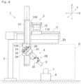
- Fig. 1 to Fig. 3B show a work device according to a first embodiment of the present invention.
- the work device 1 includes: a mount 2; a linear motion unit 3 having a base portion fixed to the mount 2; a rotation unit 4 having a base portion fixed to an output portion of the linear motion unit 3; and an end effector 5 attached to an output portion of the rotation unit 4.
- the end effector 5 performs a work on a workpiece 7 placed on a workpiece placement table 6.
- the end effector 5 may perform a work on the workpiece 7 by coming into contact therewith, or may perform a work on the workpiece 7 without coming into contact therewith.
- the work to be performed on the workpiece 7 by the end effector 5 can be enabled within a range of a work space S below a horizontal portion 2a of the mount 2.
- the linear motion unit 3 is configured to have three degrees of freedom by combining three linear motion actuators.
- the rotation unit 4 is configured to have three degrees of freedom by combining a plurality of rotation mechanisms each having one or more degrees of rotational freedom.
- the work device 1 is configured to have six degrees of freedom as a whole.
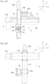
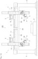
- Fig. 2A and Fig. 2B are a front view and a plan view of the linear motion unit 3, respectively.
- the linear motion unit 3 includes a first linear motion actuator 11, a second linear motion actuator 12, and a third linear motion actuator 13.
- the first linear motion actuator 11 is provided on the horizontal portion 2a of the mount 2, and includes a stage 11a which advances/retreats in the left/right direction (X-axis direction).
- the second linear motion actuator 12 is provided on the stage 11a of the first linear motion actuator 11, and includes a stage 12a which advances/retreats in the front/rear direction (Y-axis direction).
- the third linear motion actuator 13 is provided on the stage 12a of the second linear motion actuator 12, and includes a stage 13a which advances/retreats in a vertical direction (Z-axis direction).
- the first to third linear motion actuators 11, 12, and 13 are electric actuators that respectively use motors 11b, 12b, and 13b as drive sources.
- the first to third linear motion actuators 11, 12, and 13 are disposed such that the respective stages 11a, 12a, and 13a face outward relative to the work space S ( Fig. 1 ).
- a fixed portion, of the first linear motion actuator 11, that does not perform any advancing/retreating motion serves as the base portion, of the linear motion unit 3, which is fixed to the mount 2.
- the stage 13a of the third linear motion actuator 13 serves as the output portion, of the linear motion unit 3, to which the base portion of the rotation unit 4 is fixed.
- Fig. 3A and Fig. 3B are a front view and a plan view of the rotation unit 4, respectively.
- the rotation unit 4 includes: a rotation-unit attachment member 20 fixed to the output portion of the linear motion unit 3 ( Fig. 1 ); a first rotation mechanism 21 attached to the rotation-unit attachment member 20; a second rotation mechanism 22 attached to a rotating portion 21a of the first rotation mechanism 21; and a third rotation mechanism 23 attached to a rotating portion 22a of the second rotation mechanism 22.
- Rotation axes 21b, 22b, and 23b of the first to third rotation mechanisms 21, 22, and 23 are perpendicular to one another.
- Rotational drive sources of the respective rotation mechanisms 21, 22, and 23 are motors 21c, 22c, and 23c, for example.
- the rotation-unit attachment member 20 serves as a base portion, of the rotation unit 4, that is fixed to the output portion of the linear motion unit 3.
- a rotating portion 23a of the third rotation mechanism 23 serves as the output portion, of the rotation unit 4, to which the end effector 5 is attached.
- a first screw hole 14, a second screw hole 15 and a positioning hole 16 for fixing the rotation-unit attachment member 20 are provided in the stage 13a, of the third linear motion actuator 13, which is the output portion of the linear motion unit 3.
- a single first screw hole 14 is provided at a center portion of a location, on the stage 13a, at which the rotation-unit attachment member 20 is to be fixed.
- a plurality (in this embodiment, eight) of the second screw holes 15 are provided on a circle, on the stage 13a, that is centered on the first screw hole 14.
- the positioning holes 16, which are equal in number to the second screw holes 15, are provided on a circle, on the stage 13a, that is centered on the first screw hole 14 and that has a smaller radius than the circle on which the second screw holes 15 are provided.
- the rotation-unit attachment member 20 is provided with: three bolt insertion holes (not shown) arrayed on a straight line so as to correspond to the first screw hole 14 and two of the second screw holes 15; and two positioning projections (not shown) inserted in the positioning holes 16.
- Fixation of the rotation-unit attachment member 20 to the stage 13a, which is the output portion of the third linear motion actuator 13, is performed in the following procedures. First, the two positioning projections of the rotation-unit attachment member 20 are engaged with two of the positioning holes 16 of the stage 13a. Accordingly, the angle, in a front view, of the rotation-unit attachment member 20 relative to the stage 13a is determined.
- attachment bolts 24 are inserted in the three bolt insertion holes of the rotation-unit attachment member 20, and then, the respective attachment bolts 24 are screwed into the first screw hole 14 and the two second screw holes 15 of the stage 13a. Accordingly, the rotation-unit attachment member 20 is fixed to the stage 13a.
- the attachment angle of the base portion of the rotation unit 4 relative to the output portion of the linear motion unit 3 can be changed.
- the position of the end effector 5 is determined mainly by the linear motion unit 3 having three degrees of freedom, and the posture of the end effector 5 is determined by the rotation unit 4 having three degrees of freedom.
- the first to third linear motion actuators 11, 12 and 13 of the linear motion unit 3, and the first to third rotation mechanisms 21, 22 and 23 of the rotation unit 4 correspond to a position and a posture of the end effector 5 expressed in a rectangular coordinate system. Therefore, motions of the first to third linear motion actuators 11, 12 and 13 and the first to third rotation mechanisms 21, 22 and 23 corresponding to the position and the posture of the end effector 5, respectively are easily imagined, and motion pattern setting such as a posture teaching work is easily performed.
- the motion positions of the first to third linear motion actuators 11, 12 and 13, and the motion angles of the first to third rotation mechanisms 21, 22 and 23 are uniquely determined correspondingly to the position and the posture of the end effector 5. That is, no singularity is generated. Owing to these features, it is easy to imagine in what direction the distal end is to move upon when each axis is manipulated during teaching being performed. Thus, the work device 1 can be manipulated even without knowledge or experience abundantly gained over time.
- the work can be performed mainly by moving only the rotation unit 4. Therefore, the motion amount of the linear motion unit 3 can be made small, and thus, the range of possible movement of the entire device can be made small. In addition, the area of a region, in which a barrier needs to be provided, can be made small.
- the position of the end effector 5 is determined by the first to third linear motion actuators 11, 12 and 13
- linear motion of the end effector 5 can be accurately performed at high speed.
- the first to third linear motion actuators 11, 12 and 13 are used at areas that greatly influence the range of possible movement, the motion range can be easily restricted with use of a mechanical stopper, a limit sensor or the like in accordance with the type of the work and the ambient environment.
- the work space S can be made wider.
- the linear motion unit 3 and the rotation unit 4 are separately provided, only one of the units may be changed in a case where the specifications of the work device 1 are changed.
- the form of the rotation unit 4 may be changed from the form shown in Figs. 3A and 3B to, for example, a form shown in Fig. 5 , a form shown in Fig. 12 or a form shown in Fig. 14 described later. Accordingly, the same components can be used among work devices 1 that are different in specifications from one another.
- the rotation-unit attachment member 20, which is the base portion of the rotation unit 4 is attached to the stage 13a, of the third linear motion actuator 13, which is the output portion of the linear motion unit 3, such that the attachment angle can be changed by means of the attachment bolts 24.
- the configuration of the device can be easily changed in accordance with the type of the work and the ambient environment.
- the work device 1 can coexist with humans since the motion amount of the entire device at the time of a delicate work is small. That is, a work similar to a manual work that is performed by a human can be automatically performed. In addition, a setup changeover time period and an adjustment time period can be shortened, and high-speed motion can be performed, whereby the productivity can be improved.
- a barrier such as a cover for covering the work device 1. Since the range of possible movement of the work device 1 is determined mainly by the first to third linear motion actuators 11, 12 and 13, the barrier can have a simple shape such as that of a rectangular parallelepiped. In this case, the volume of an internal space of the barrier and the volume of a region within which the movable portion of the device is movable is approximately equal to each other. Therefore, a compact configuration can be obtained even if the barrier is provided.
- Fig. 4 to Fig. 9 show a second embodiment of the present invention.
- the rotation unit 4 in the work device 1 includes a first rotation mechanism 21, which is a rotation mechanism having one degree of freedom, and a second rotation mechanism which is a link actuation device 29 having two degrees of freedom. That is, the second rotation mechanism 22 and the third rotation mechanism 23 in the first embodiment shown in Fig. 1 are replaced by the link actuation device 29.
- the first rotation mechanism 21 corresponds to "another rotation mechanism other than the link actuation device 29".
- the other structures are the same as those of the first embodiment in Fig. 1 .
- the link actuation device 29 includes a parallel link mechanism 30 and a posture-controlling actuator 31 which actuates the parallel link mechanism 30.
- Fig. 6 and Fig. 7 are perspective views of the parallel link mechanism 30, and show states that are different from each other.
- the parallel link mechanism 30 includes: a proximal-end-side link hub 32; a distal-end-side link hub 33; and three link mechanisms 34 with which the distal-end-side link hub 33 is connected to the proximal-end-side link hub 32 so as to be changeable in posture relative to the proximal-end-side link hub 32.
- Fig. 5 shows only one of the link mechanisms 34. The number of the link mechanisms 34 may be four or more.
- Each link mechanism 34 is a quadric chain link mechanism having four revolute pairs, which mechanism 34 includes a proximal-side end link member 35, a distal-side end link member 36, and a center link member 37.
- the proximal-side and distal-side end link members 35 and 36 are L-shaped.
- One end of the proximal-side end link member 35 is rotatably connected to the proximal-end-side link hub 32, and one end of the distal-side end link member 36 is rotatably connected to the distal-end-side link hub 33.
- the center link member 37 has opposed ends to which the other ends of the proximal-side and distal-side end link members 35 and 36 are rotatably connected, respectively.
- the parallel link mechanism 30 has a structure obtained by combining two spherical link mechanisms, in which the central axis of a revolute pair between the proximal-end-side link hub 32 and the proximal-side end link member 35 and the central axis of a revolute pair between the proximal-side end link member 35 and the center link member 37, intersect with each other at a proximal-end-side spherical link center PA ( Fig. 5 ).
- the distances to the proximal-end-side spherical link center PA from the respective revolute pairs between the proximal-end-side link hub 32 and the proximal-side end link members 35 are equal to one another, and the distances to the proximal-end-side spherical link center PA from the respective revolute pairs between the proximal-side end link members 35 and the center link members 37 are also equal to one another.
- the distances to the distal-end-side spherical link center PB from the respective revolute pairs between the distal-end-side link hub 33 and the distal-side end link members 36 are equal to one another, and the distances to the distal-end-side spherical link center PB from the respective revolute pairs between the distal-side end link members 36 and the center link members 37 are also equal to one another.
- the central axes of the respective revolute pairs between the proximal-side and distal-side end link members 35, 36 and the center link member 37 may intersect with each other at an intersection angle ⁇ ( Fig. 5 ), or may be parallel to each other.
- Fig. 8 is a cross-sectional view taken along a line VIII-VIII in Fig. 5 .
- Fig. 8 shows the relationship among a central axis O1 of the revolute pair between the proximal-end-side link hub 32 and each proximal-side end link member 35, a central axis O2 of the revolute pair between the proximal-side end link member 35 and the corresponding center link member 37, and the proximal-end-side spherical link center PA. That is, a point, at which the central axis O1 and the central axis O2 intersect with each other, is the proximal-end-side spherical link center PA.
- an angle ⁇ is 90°, the angle ⁇ being formed by: the central axis O1 of the revolute pair between the link hub 32 (33) and the end link member 35 (36); and the central axis O2 of the revolute pair between the end link member 35 (36) and the center link member 37.
- the angle ⁇ may be other than 90°.
- the three link mechanisms 34 have geometrically identical forms.
- geometrically identical forms intends to mean that, as shown in Fig. 9 , a geometric model depicted with straight lines that represent the link members 35, 36, and 37, i.e., a model depicted with the revolute pairs and straight lines connecting the revolute pairs to each other, has such a shape that a proximal-end-side portion thereof and a distal-end-side portion thereof are symmetric with each other relative to a center portion of the center link member 37.
- Fig. 9 is a view in which one of the link mechanisms 34 is expressed with straight lines.
- the parallel link mechanism 30 in the present embodiment is of a rotation symmetrical type. That is, a positional relationship is established in which a proximal side portion composed of the proximal-end-side link hub 32 and the proximal-side end link member 35 is rotationally symmetric, about a center line C of the center link member 37, with a distal side portion composed of the distal-end-side link hub 33 and the distal-side end link member 36.
- the center portions of the center link members 37 are located on the same orbital circle.
- the proximal-end-side link hub 32, the distal-end-side link hub 33 and the three link mechanisms 34 cooperate together to form a mechanism having two degrees of freedom, in which the distal-end-side link hub 33 is rotatable, about orthogonal two axes, relative to the proximal-end-side link hub 32.
- the posture of the distal-end-side link hub 33 is changeable relative to that of the proximal-end-side link hub 32 with two degrees of rotational freedom.
- This mechanism having two degrees of freedom is compact but provides a wide range of possible movement of the distal-end-side link hub 33 relative to the proximal-end-side link hub 32.
- a straight line that passes the spherical link center PA, PB and that intersects, at the right angle, with the central axis O1 ( Fig. 8 ) of the revolute pair between the link hub 32, 33 and each end link member 35, 36, is defined as a central axis QA, QB of the link hub 32, 33.
- the maximum value of a bend angle ⁇ ( Fig. 9 ) formed by the central axis QA of the proximal-end-side link hub 32 and the central axis QB of the distal-end-side link hub 33 can be set to about ⁇ 90°.
- an angle of traverse ⁇ Fig.
- the bend angle ⁇ refers to a vertical angle formed when the central axis QB of the distal-end-side link hub 33 is tilted relative to the central axis QA of the proximal-end-side link hub 32.
- the angle of traverse ⁇ refers to a horizontal angle formed when the central axis QB of the distal-end-side link hub 33 is tilted around the central axis QA of the proximal-end-side link hub 32.
- FIG. 7 shows a state where the central axis QB of the distal-end-side link hub 33 is tilted at a certain operating angle relative to the central axis QA of the proximal-end-side link hub 32. Even if the posture is changed, a distance L ( Fig. 9 ) between the proximal-end-side and distal-end-side spherical link centers PA and PB is unchanged.
- the proximal side portion composed of the proximal-end-side link hub 32 and the proximal-side end link members 35, and the distal side portion composed of the distal-end-side link hub 33 and the distal-side end link members 36 move in the same manner owing to geometrical symmetry. Accordingly, when transmitting rotation from the proximal end side to the distal end side, the parallel link mechanism 30 functions as a constant velocity universal joint that is rotated at a constant velocity with the same rotation angle being formed on the proximal end side and the distal end side.
- the proximal-end-side link hub 32 includes a proximal-end member 40 and three rotational shaft connection members 41 provided integrally with the proximal-end member 40.
- a circular through hole 40 is formed at a center portion of the proximal-end member 40, and three rotational shaft connection members 41 are arranged around the through hole 40a at equal intervals in the circumferential direction.
- the center of the through hole 40a is located on the central axis QA ( Fig. 5 ) of the proximal-end-side link hub 32.
- a rotational shaft 42 is rotatably connected such that the axis thereof intersects with the central axis QA of the proximal-end-side link hub 32.
- One end of the proximal-side end link member 35 is connected to the rotational shaft 42.
- the rotational shaft 42 is rotatably supported by the rotational shaft connection member 41 via two bearings 43.
- the bearings 43 ball bearings such as deep groove ball bearings or angular contact ball bearings are used, for example.
- the bearings 43 are disposed in a hollow hole 44 of the tubular rotational shaft connection member 41 in a fitted state, and are fixed by a method such as press-fitting, adhesion or crimping.
- the types of the bearings provided to the other revolute pair portions, and a disposing method for these bearings are the same as above.
- the one end of the proximal-side end link member 35 and a fan-shaped bevel gear 45 (described later) are joined to the rotational shaft 42, and are both rotated integrally with the rotational shaft 42.
- a cut portion 46 is formed at the one end of the proximal-side end link member 35, and the rotational shaft connection member 41 is disposed between inner-side and outer-side rotational shaft support portions 47 and 48 which are both-side portions of the cut portion 46.
- the bevel gear 45 is disposed so as to be in contact with the inner surface of the inner-side rotational shaft support portion 47.
- the rotational shaft 42 is inserted through: a through hole formed in the bevel gear 45; a through hole formed in the inner-side rotational shaft support portion 47; an inner ring of each bearing 43; and a through hole formed in the outer-side rotational shaft support portion 48.
- the bevel gear 45, the inner-side and outer-side rotational shaft support portions 47 and 48, and the inner ring of the bearing 43 are sandwiched and joined by a head portion 42a of the rotational shaft 42 and a nut 50 screwed onto a screw portion 42b of the rotational shaft 42.
- Spacers 51 and 52 are interposed between the bearing 43 and the inner-side and outer-side rotational shaft support portions 47 and 48, and a preload is applied to the bearing 43 when the nut 50 is screwed.
- a rotational shaft 55 is joined to the other end of the proximal-side end link member 35.
- the rotational shaft 55 is rotatably connected to one end of the center link member 37 via two bearings 53.
- a cut portion 56 is formed at the other end of the proximal-side end link member 35, and the one end of the center link member 37 is disposed between inner-side and outer-side rotational shaft support portions 57 and 58 which are both-side portions of the cut portion 56.
- the rotational shaft 55 is inserted through: a through hole formed in the outer-side rotational shaft support portion 58; an inner ring of each bearing 53; and a through hole formed in the inner-side rotational shaft support portion 57.
- the inner-side and outer-side rotational shaft support portions 57 and 58 and the inner ring of the bearing 53 are sandwiched and joined by a head portion 55a of the rotational shaft 55 and a nut 60 screwed onto a screw portion 55b of the rotational shaft 55.
- Spacers 61 and 62 are interposed between the bearing 53 and the inner-side and outer-side rotational shaft support portions 57 and 58, and preload is applied to the bearing 53 when the nut 60 is screwed.
- the distal-end-side link hub 33 includes a distal end member 70 and three rotational shaft connection members 71 provided on the inner surface of the distal end member 70 so as to be arranged at equal interval in the circumferential direction.
- the center of a circle, along which the rotational shaft connection members 71 are arranged, is located on the central axis QB of the distal-end-side link hub 33.
- a rotational shaft 73 is rotatably connected such that the axis thereof intersects with the central axis QB of the link hub.
- One end of the distal-side end link member 36 is connected to the rotational shaft 73 of the distal-end-side link hub 33.
- a rotational shaft 75 rotatably connected to the other end of the center link member 37 is connected to the other end of the distal-side end link member 36.
- the rotational shaft 73 of the distal-end-side link hub 33 and the rotational shaft 75 of the center link member 37 are rotatably connected to the rotational shaft connection member 71 and the other end of the center link member 37, respectively, via two bearings (not shown).
- the parallel link mechanism 30 is disposed on the first rotation mechanism 21 by connecting the proximal-end member 40 to a base member 80 via a plurality of shafts 81.
- the central axis QA of the proximal-end-side link hub 32 and the rotation axis 21b of the first rotation mechanism 21 are located on the same line.
- the base member 80 is fixed to the rotating portion 21a of the first rotation mechanism 21.
- a cover 82 is disposed between the outer circumferential edge of the proximal-end member 40 and the outer circumferential edge of the base member 80.
- a portion between the proximal-end member 40 and the base member 80 is a shielded space 83 shielded from the outside by the cover 82.
- the posture-controlling actuator 31 for actuating the parallel link mechanism 30 is disposed in the shielded space 83, and is attached to the proximal-end member 40.
- the number of the posture-controlling actuators 31 is equal to that of the link mechanisms 34, i.e., three.
- Each posture-controlling actuator 31 is implemented by, for example, a rotary actuator such as a motor.
- the bevel gear 76 and the fan-shaped bevel gear 45 cooperate to form a speed reducer 77 of axis-orthogonal configuration.
- a mechanism other than the bevel gears e.g., a worm mechanism may be used to form the speed reducer of axis-orthogonal configuration.
- the posture-controlling actuators 31 equal in number to the link mechanisms 34 are provided in the second embodiment, the posture-controlling actuators 31 only have to be provided to at least two of the three link mechanisms 34. As long as this is satisfied, the posture of the distal-end-side link hub 33 relative to the proximal-end-side link hub 32 can be determined.
- the link actuation device 29 rotationally drives each posture-controlling actuator 31, thereby actuating the parallel link mechanism 30. Specifically, when the posture-controlling actuator 31 is rotationally driven, the rotation thereof is transmitted to the rotational shaft 42 while being reduced in speed via the speed reducer 77 of axis-orthogonal configuration. By so doing, the angle of the proximal-side end link member 35 relative to the proximal-end-side link hub 32 is changed. Accordingly, the position and the posture of the distal-end-side link hub 33 relative to the proximal-end-side link hub 32 are determined. Since the central axis QA of the proximal-end-side link hub 32 and the rotation axis 21b of the first rotation mechanism 21 are located on the same line, calculation of coordinates is easily performed.
- the central axis QA of the proximal-end-side link hub 32 and the rotation axis 21b of the first rotation mechanism 21 are located on the same line, a worker can easily imagine the motion of the work device 1, and thus, can easily manipulate the work device 1.
- a work can be performed while the posture of the end effector 5 is being changed by changing only the angle in the remaining one degree of freedom (e.g., an angle about the central axis QB of the distal-end-side link hub 33).
- the link actuation device 29 has a wide range of possible movement, and is capable of smooth motion. Thus, if the rotation unit 4 includes the link actuation device 29, a delicate work can be performed at high speed. In addition, since the link actuation device 29 has a compact configuration but has a wide range of possible movement, the entire work device 1 has a compact configuration.
- the first rotation mechanism 21 is disposed at the proximal end side of the link actuation device 29 and the end effector 5 is mounted to the distal-end-side link hub 33. Accordingly, load on the link actuation device 29 can be reduced, and thus, the link actuation device 29 can be made compact and can be reduced in weight.
- the parallel link mechanism 30 of the link actuation device 29 functions as a constant velocity universal joint. Therefore, owing to coordinated control of the link actuation device 29 and the first rotation mechanism 21, a work can be easily performed while the posture of the end effector 5 is being changed in terms of only the angle about the central axis QB of the distal-end-side link hub 33. However, a cable that is connected to each posture-controlling actuator 31 needs to be taken into consideration, and thus, the rotation angle is restricted.
- a rotation unit 4 is provided in which the order of the first rotation mechanism 21 and the link actuation device 29 is reversed relative to that in the second embodiment in Fig. 5 .
- the central axis QB of the distal-end-side link hub 33 of the link actuation device 29 and the rotation axis 21b of the first rotation mechanism 21 are located on the same line.
- the other configurations are the same as those in the second embodiment shown in Fig. 5 .
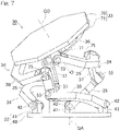
- Fig. 11 to Fig. 13 show a fourth embodiment of the present invention.
- the rotation unit 4 in this work device 1 includes the first rotation mechanism 21, which is a rotation mechanism having one degree of freedom, and the link actuation device 29, which is a rotation mechanism having two degrees of freedom, as in the second embodiment shown in Fig. 4 .
- the difference between the work device 1 according to the fourth embodiment and that according to the second embodiment shown in Fig. 4 is that the first rotation mechanism 21 is disposed at a center portion among the posture-controlling actuators 31 of the link actuation device 29.
- the first rotation mechanism 21 includes: a fixed portion 90 fixed to the base member 80; a rotating portion 91 fixed to the proximal-end member 40 of the link actuation device 29; two bearings 92 supporting the rotating portion 91 such that the rotating portion 91 is rotatable relative to the fixed portion 90; a motor 93, which is a drive source, provided at the fixed portion 90; and a pair of spur gears 94 and 95 through which rotation of the motor 93 is transmitted to the rotating portion 91.
- the base member 80 is fixed to the rotation-unit attachment member 20.
- the fixed portion 90 includes: a first attachment member 96 fixed to the base member 80 and having a horseshoe-shaped cross section; and a second attachment member 97 having a bottom portion 97a fixed to the first attachment member 96.
- the second attachment member 97 has a tubular portion 97b extending from the outer circumferential edge of the bottom portion 97a to the upper side of Fig. 12 .
- the rotating portion 91 is fixed to the proximal-end member 40 of the proximal-end-side link hub 32 such that a rotation axis 91a of the rotating portion 91 and the central axis QA of the proximal-end-side link hub 32 are on the same line.
- the two bearings 92 are arranged on the inner circumference of the tubular portion 97b of the second attachment member 97.
- the motor 93 is disposed in a recessed portion 96a of the first attachment member 96 having a horseshoe-shaped cross section, and is fixed to the bottom portion 97a of the second attachment member 97.
- An output shaft 93a of the motor 93 extends upward so as to penetrate the bottom portion 97a of the second attachment member 97, and has an upper end to which the driving-side spur gear 94 is attached.
- the driving-side spur gear 94 meshes with the driven-side spur gear 95 attached to the rotating portion 91.
- the driven-side spur gear 95 is fitted to the outer circumference of the rotating portion 91.
- a screw portion is formed on the lower end of the rotating portion 91, and, by means of a nut 98 screwed onto the screw portion, the spur gear 95 is fastened and fixed to the rotating portion 91.
- the bottom portion 97a of the second attachment member 97, the rotating portion 91, and the proximal-end member 40 respectively have wiring holes 100, 101, and 102 penetrating therethrough along the rotation axis 91a of the rotating portion 91.
- the cover 82 is attached to the outer circumferential edge of the proximal-end member 40 so as to extend to an area near the outer circumferential edge of the base member 80. The cover 82 and the base member 80 are not joined to each other.
- the three posture-controlling actuators 31 of the link actuation device 29 are arranged on an imaginary circle on the proximal-end member 40, and the rotational drive force of the rotational output shaft 31a of each posture-controlling actuator 31 is transmitted to the link mechanism 34 through speed reducer 77 of axis-orthogonal configuration.
- the first rotation mechanism 21 can be disposed at the center portion in the arrangement of the posture-controlling actuators 31, as in the fourth embodiment. Accordingly, the rotation unit 4 has a compact configuration.
- the internal space of the link actuation device 29 means a space enclosed by the proximal-end-side link hub 32, the distal-end-side link hub 33 and the link mechanisms 34.
- Fig. 14 is a front view of a main portion of a rotation unit of a work device according to a fifth embodiment of the present invention.
- the first rotation mechanism 21 is disposed at a center portion among the posture-controlling actuators 31 of the link actuation device 29.
- the fifth embodiment is the same as the fourth embodiment shown in Fig. 12 .
- the fifth embodiment is different from the fourth embodiment shown in Fig. 12 in that a hollow shaft motor 110 is used as the drive source of the first rotation mechanism 21.
- the hollow shaft motor 110 has a motor body 110a fixed to the base member 80 via a motor attachment member 111.
- the hollow shaft motor 110 has an output shaft 110b to which the proximal-end member 40 of the proximal-end-side link hub 32 is fixed.
- the hollow shaft motor 110 has therein a wiring hole 112 penetrating the motor body 110a and the output shaft 110b in the axial direction.
- the proximal-end member 40 of the proximal-end-side link hub 32 has therein a wiring hole 113 coaxially with the wiring hole 112.
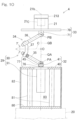
- Fig. 15 to Fig. 17 show a schematic configuration of a dual-arm work device according to a sixth embodiment of the present invention.
- a dual-arm work device 120 is obtained by arraying two work devices 1, each of which is used in the fourth embodiment shown in Fig. 11 , such that the work devices 1 are geometrically symmetric with each other.
- the mounts 2 and 2 of the respective work devices 1 have the horizontal portions 2a and 2a, and the respective ends of the horizontal portions 2a, 2a are connected to each other, thereby forming a portal-shaped mount 2A as a whole.
- the work devices 1 according to the fourth embodiment shown in Fig. 11 are used, but work devices according to another embodiment may be used.
- the workpiece 7 to be worked on can be passed beneath the work devices 1 and 1.
- a conveyor capable of conveying the workpiece 7 in a direction orthogonal to the surface of the sheet of Fig. 15 may be used, and the work devices 1 and 1 may be provided above a conveyor line of the conveyor.
- the range of possible movement, in the widthwise direction, of each of the work devices 1 and 1 can be restricted to be within a range, in the widthwise direction, of the mount 2A.
- the occupation areas of the work devices 1 and 1 can be made small.
- the ranges of possible movement of the work devices 1 and 1 are restricted, a worker can easily perform a work even when the worker is located at a side of the work devices 1 and 1.
- Fig. 17 is a plan view of the linear motion units 3 and 3 of the dual-arm work device 120 shown in Fig. 15 and Fig. 16 .
- the motor 11b of the first linear motion actuator 11 and the motor 12b of the second linear motion actuator 12 are disposed on the central axes of the linear motion actuators 11 and 12, respectively.
- Fig. 18 is a plan view showing linear motion units 3 and 3 according to a seventh embodiment of the present invention.
- the motor 11b of the first linear motion actuator 11 and the motor 12b of the second linear motion actuator 12 are disposed so as to be offset from the central axes of the linear motion actuators 11 and 12, respectively, and the rotations of the motors 11b and 12b are transmitted to drive portions of the linear motion actuators 11 and 12 via motive-power transmitting member 121 such as chains.
- the linear motion unit 3 may be changed to that in the sixth embodiment shown in Fig. 17 or that in the seventh embodiment shown in Fig. 18 in accordance with the specifications of the dual-arm work device 120. Such changes can be easily performed since the linear motion unit 3 and the rotation unit 4 are separately provided.
Landscapes
- Engineering & Computer Science (AREA)
- Mechanical Engineering (AREA)
- Robotics (AREA)
- General Engineering & Computer Science (AREA)
- Manipulator (AREA)
Claims (8)
- Arbeitsvorrichtung (1), die eine Arbeit unter Verwendung eines Endeffektors (5) verrichtet und sechs Freiheitsgrade aufweist, wobei die Arbeitsvorrichtung (1) Folgendes umfasst:eine Linearbewegungseinheit (3), die durch Kombinieren dreier Linearbewegungsaktoren (11, 12, 13) erhalten wird, um drei Freiheitsgrade aufzuweisen; undeine Rotationseinheit (4), die durch Kombinieren einer Mehrzahl von Rotationsmechanismen (21, 22, 23) erhalten wird, die jeweils einen oder mehrere rotatorische Freiheitsgrade aufweisen, um drei Freiheitsgrade aufzuweisen, wobeiein Basisabschnitt der Linearbewegungseinheit (3) an einer Halterung (2) der Arbeitsvorrichtung (1) fixiert ist,ein Basisabschnitt der Rotationseinheit (4) an einem Ausgangsabschnitt (13a) der Linearbewegungseinheit (3) fixiert ist, undder Endeffektor (5) an einem Ausgangsabschnitt (23a) der Rotationseinheit (4) montiert ist,dadurch gekennzeichnet, dass
ein Befestigungswinkel des Basisabschnitts (20) der Rotationseinheit (4) relativ zu dem Ausgangsabschnitt (13a) der Linearbewegungseinheit (3) änderbar ist. - Arbeitsvorrichtung (1) nach Anspruch 1, wobeijeder der Linearbewegungsaktoren (11, 12, 13) eine Stufe (11a, 12a, 13a) umfasst, die ein sich vorschiebender/zurückziehender Abschnitt ist, unddie Linearbewegungsaktoren (11, 12, 13) der Linearbewegungseinheit (3) derart angeordnet sind, dass die jeweiligen Stufen (11a, 12a, 13a) relativ zu einem Arbeitsraum (S) nach außen weisen, so dass der Arbeitsraum (S) verbreitert werden kann, wobei der Arbeitsraum (S) ein Bereich ist, in dem durch den Endeffektor (5) zu verrichtende Arbeit ermöglicht werden kann.
- Arbeitsvorrichtung (1) nach Anspruch 1 oder 2, wobeimindestens einer der Mehrzahl von Rotationsmechanismen (21, 22, 23) in der Rotationseinheit (4) eine Verbindungsbetätigungsvorrichtung (29) ist, die zwei Freiheitsgrade aufweist,wobei die Verbindungsbetätigungsvorrichtung (29) Folgendes umfasst: eine proximalendseitige Verbindungsnabe (32); eine distalendseitige Verbindungsnabe (33); und drei oder mehr Verbindungsmechanismen (34), wobei die distalendseitige Verbindungsnabe (33) mit der proximalendseitigen Verbindungsnabe (32) derart verbunden ist, dass ihre Lage relativ zu der proximalendseitigen Verbindungsnabe (32) über die drei oder mehr Verbindungsmechanismen (34) änderbar ist,wobei jeder Verbindungsmechanismus (34) Folgendes umfasst:ein proximalseitiges Endverbindungsglied (35), das ein Ende aufweist, das mit der proximalendseitigen Verbindungsnabe (32) rotatorisch verbunden ist;ein distalseitiges Endverbindungsglied (36), das ein Ende aufweist, das mit der distalendseitigen Verbindungsnabe (33) rotatorisch verbunden ist; undein mittleres Verbindungsglied (37), das entgegengesetzte Enden aufweist, die mit den anderen Enden des proximalseitigen Endverbindungsglieds (35) bzw. des distalseitigen Endverbindungsglieds (36) rotatorisch verbunden sind, undwobei zwei oder mehrere Verbindungsmechanismen (34) aus den drei oder mehreren Verbindungsmechanismen (34) jeweils einen Lagesteuerungsaktor (31) umfassen, der dazu ausgelegt ist, eine Lage der distalendseitigen Verbindungsnabe (33) relativ zu der proximalendseitigen Verbindungsnabe (32) beliebig zu verändern.
- Arbeitsvorrichtung (1) nach Anspruch 3, wobeiein Punkt, an dem sich eine Mittelachse (O1) eines Drehgelenkpaars zwischen der proximalendseitigen Verbindungsnabe (32) und jedem proximalseitigen Endverbindungsglied (35) mit einer Mittelachse (O2) eines Drehgelenkpaars zwischen dem proximalseitigen Endverbindungsglied (35) und dem entsprechenden mittleren Verbindungsglied (37) schneidet, als ein proximalendseitiger Kugelverbindungsmittelpunkt (PA) bezeichnet ist,eine gerade Linie, die durch den proximalendseitigen Kugelverbindungsmittelpunkt (PA) verläuft und die sich mit der Mittelachse (O1) des Drehgelenkpaars zwischen der proximalendseitigen Verbindungsnabe (32) und dem proximalseitigen Endverbindungsglied (35) in einem rechten Winkel schneidet, als eine Mittelachse (QA) der proximalendseitigen Verbindungsnabe (32) bezeichnet ist,ein Punkt, an dem sich eine Mittelachse eines Drehgelenkpaars zwischen der distalendseitigen Verbindungsnabe (33) und jedem distalseitigen Endverbindungsglied (36) mit einer Mittelachse eines Drehgelenkpaars zwischen dem distalseitigen Endverbindungsglied (36) und dem entsprechenden mittleren Verbindungsglied (37) schneidet, als ein distalendseitiger Kugelverbindungsmittelpunkt (PB) bezeichnet ist,eine gerade Linie, die durch den distalendseitigen Kugelverbindungsmittelpunkt (PB) verläuft und die sich mit der Mittelachse des Drehgelenkpaars zwischen der distalendseitigen Verbindungsnabe (33) und dem distalseitigen Endverbindungsglied (36) in einem rechten Winkel schneidet, als eine Mittelachse der distalendseitigen Verbindungsnabe (33) bezeichnet ist, unddie Mittelachse der proximalendseitigen Verbindungsnabe (32) oder die Mittelachse der distalendseitigen Verbindungsnabe (33) und eine Rotationsachse eines anderen Rotationsmechanismus außer der Verbindungsbetätigungsvorrichtung (29) auf einer selben Linie positioniert sind.
- Arbeitsvorrichtung (1) nach Anspruch 4, wobeiein rotierender Abschnitt des anderen Rotationsmechanismus direkt oder indirekt an die proximalendseitige Verbindungsnabe (32) der Verbindungsbetätigungsvorrichtung (29) gefügt ist, undder Endeffektor (5) an der distalendseitigen Verbindungsnabe (33) der Verbindungsbetätigungsvorrichtung (29) montiert ist.
- Arbeitsvorrichtung (1) nach Anspruch 5, wobeidie zwei oder mehr Lagesteuerungsaktoren (31) der Verbindungsbetätigungsvorrichtung (29) rotatorische Aktoren sind,rotatorische Ausgangswellen der rotatorischen Aktuatoren (31) derart angeordnet sind, dass sie parallel zu der Mittelachse (QA) der proximalendseitigen Verbindungsnabe (32) sind,rotatorische Antriebskräfte der rotatorischen Ausgangswellen auf die Verbindungsmechanismen (34) über Drehzahlreduzierer einer achsenorthogonalen Auslegung übertragen werden, undder andere Rotationsmechanismus an einem mittleren Abschnitt in der Anordnung der Lagesteuerungsaktoren (31) angeordnet ist.
- Arbeitsvorrichtung (1) nach einem der Ansprüche 4 bis 6, wobei
der andere Rotationsmechanismus eine Verkabelungsöffnung (100, 101, 102, 112, 113) darin aufweist, die mindestens einen rotierenden Abschnitt davon in einer axialen Richtung durchdringt. - Doppelarmige Arbeitsvorrichtung (120), die durch Anordnen von zwei Arbeitsvorrichtungen (1) erhalten wird, von denen jede in einem der Ansprüche 1 bis 7 beansprucht ist, so dass die Arbeitsvorrichtungen (1) geometrisch symmetrisch zueinander sind, wobei die Halterungen (2) der jeweiligen Arbeitsvorrichtungen (1) horizontale Abschnitte (2a) aufweisen, und jeweilige Enden der horizontalen Abschnitte (2a) miteinander verbunden sind, wodurch in der Gesamtheit eine portalförmige Halterung (2A) gebildet wird.
Applications Claiming Priority (2)
| Application Number | Priority Date | Filing Date | Title |
|---|---|---|---|
| JP2016084171A JP6719956B2 (ja) | 2016-04-20 | 2016-04-20 | 双腕型作動装置 |
| PCT/JP2017/014683 WO2017183505A1 (ja) | 2016-04-20 | 2017-04-10 | 作業装置および双腕型作業装置 |
Publications (3)
| Publication Number | Publication Date |
|---|---|
| EP3446836A1 EP3446836A1 (de) | 2019-02-27 |
| EP3446836A4 EP3446836A4 (de) | 2019-04-24 |
| EP3446836B1 true EP3446836B1 (de) | 2023-04-05 |
Family
ID=60115942
Family Applications (1)
| Application Number | Title | Priority Date | Filing Date |
|---|---|---|---|
| EP17785845.3A Active EP3446836B1 (de) | 2016-04-20 | 2017-04-10 | Arbeitsvorrichtung und doppelarmarbeitsvorrichtung |
Country Status (5)
| Country | Link |
|---|---|
| US (1) | US11154994B2 (de) |
| EP (1) | EP3446836B1 (de) |
| JP (1) | JP6719956B2 (de) |
| CN (1) | CN109070341A (de) |
| WO (1) | WO2017183505A1 (de) |
Families Citing this family (14)
| Publication number | Priority date | Publication date | Assignee | Title |
|---|---|---|---|---|
| JP6067805B1 (ja) * | 2015-09-07 | 2017-01-25 | Ntn株式会社 | リンク作動装置を用いた複合作業装置 |
| JP6719956B2 (ja) * | 2016-04-20 | 2020-07-08 | Ntn株式会社 | 双腕型作動装置 |
| JP6765284B2 (ja) | 2016-11-10 | 2020-10-07 | Ntn株式会社 | 作動装置および双腕型作動装置 |
| JP2018075689A (ja) * | 2016-11-11 | 2018-05-17 | Ntn株式会社 | 作動装置および双腕型作動装置 |
| US11267315B2 (en) | 2017-10-02 | 2022-03-08 | Marelli Cabin Comfort Japan Corporation | Air-conditioning device |
| JP7140508B2 (ja) * | 2018-02-26 | 2022-09-21 | Ntn株式会社 | パラレルリンク機構を用いた作業装置およびその制御方法 |
| JP7289644B2 (ja) * | 2018-12-07 | 2023-06-12 | Ntn株式会社 | 作業装置 |
| WO2020196164A1 (ja) * | 2019-03-22 | 2020-10-01 | Ntn株式会社 | パラレルリンク機構およびリンク作動装置 |
| CN109932692A (zh) * | 2019-03-28 | 2019-06-25 | 尹建霞 | 一种共轴双向伺服雷达转台 |
| CN110919638B (zh) * | 2019-11-15 | 2021-11-02 | 华中科技大学 | 一种3+4构型双臂协作机器人加工系统及方法 |
| JP2022082090A (ja) * | 2020-11-20 | 2022-06-01 | Ntn株式会社 | 作業装置 |
| CN113146590A (zh) * | 2021-05-21 | 2021-07-23 | 莱茵科斯特智能科技(青岛)有限公司 | 一种用于安装产品附件的工作站及用于安装附件的机械手 |
| WO2022269693A1 (ja) * | 2021-06-21 | 2022-12-29 | 東京ロボティクス株式会社 | リンク機構、ロボットアーム及び双腕ロボット |
| JP2023047742A (ja) * | 2021-09-27 | 2023-04-06 | Ntn株式会社 | 作業装置 |
Family Cites Families (46)
| Publication number | Priority date | Publication date | Assignee | Title |
|---|---|---|---|---|
| US4723460A (en) * | 1984-04-12 | 1988-02-09 | Rosheim Mark E | Robot wrist actuator |
| DE3626610A1 (de) * | 1986-08-06 | 1988-02-18 | Fibro Gmbh | Portalsystem |
| JPH07178684A (ja) * | 1993-12-22 | 1995-07-18 | Toshiba Corp | ロボットアーム |
| JP2835002B2 (ja) * | 1994-06-27 | 1998-12-14 | 菱栄エンジニアリング株式会社 | 自動バリ取り方法 |
| JP4060608B2 (ja) * | 2001-03-14 | 2008-03-12 | ユニバーサル造船株式会社 | 溶接装置 |
| JP2005144627A (ja) * | 2003-11-18 | 2005-06-09 | Ntn Corp | リンク作動装置 |
| WO2005053913A1 (ja) * | 2003-12-03 | 2005-06-16 | Ntn Corporation | リンク作動装置 |
| US7971505B2 (en) * | 2004-03-11 | 2011-07-05 | Ntn Corporation | Link actuating device |
| JP2005329521A (ja) | 2004-05-21 | 2005-12-02 | Denso Wave Inc | 多関節型ロボット |
| US7501603B2 (en) * | 2005-03-23 | 2009-03-10 | Vojislav Kalanovic | Positioning apparatus and method incorporating modular gimbal unit and jewelry processing system incorporating the positioning apparatus |
| JP4528312B2 (ja) | 2007-02-02 | 2010-08-18 | 川田工業株式会社 | 双腕ロボットの肩幅空間制限装置及びその装置を具えた双腕ロボット |
| JP2009202331A (ja) * | 2007-07-27 | 2009-09-10 | Nsk Ltd | マニピュレータ、マニピュレータの駆動方法、マニピュレータシステム及び微小操作対象物の操作方法 |
| WO2010002043A1 (en) * | 2008-06-30 | 2010-01-07 | Seoul National University Industry Foundation | Robot having rotatable arm |
| JP2010260139A (ja) * | 2009-05-08 | 2010-11-18 | Ntn Corp | 遠隔操作型加工ロボット |
| CN101559597B (zh) * | 2009-05-12 | 2011-04-20 | 哈尔滨工程大学 | 多功能龙门式七轴工业机器人 |
| JP5528207B2 (ja) * | 2010-05-19 | 2014-06-25 | Ntn株式会社 | リンク作動装置 |
| KR101213452B1 (ko) * | 2010-08-27 | 2012-12-18 | 한양대학교 에리카산학협력단 | 4자유도 병렬기구를 이용한 마스터?슬레이브 시스템 |
| CN101947781A (zh) * | 2010-08-30 | 2011-01-19 | 苏州博实机器人技术有限公司 | 一种模块化多控制直角坐标机器人 |
| JP5951224B2 (ja) * | 2011-11-02 | 2016-07-13 | Ntn株式会社 | リンク作動装置の原点位置初期設定方法およびリンク作動装置 |
| US9316266B2 (en) * | 2011-11-04 | 2016-04-19 | Ntn Corporation | Parallel link mechanism, constant velocity universal joint, and link actuator |
| WO2013141138A1 (ja) * | 2012-03-23 | 2013-09-26 | Ntn株式会社 | リンク作動装置 |
| CN102785239B (zh) * | 2012-07-23 | 2015-04-29 | 东莞市李群自动化设备有限公司 | 一种六自由度工业机器人 |
| JP6029969B2 (ja) * | 2012-12-18 | 2016-11-24 | Ntn株式会社 | リンク作動装置 |
| WO2014156784A1 (ja) * | 2013-03-26 | 2014-10-02 | Ntn株式会社 | リンク作動装置の制御装置 |
| JP6104701B2 (ja) * | 2013-05-16 | 2017-03-29 | Ntn株式会社 | リンク作動装置 |
| JP2015085427A (ja) * | 2013-10-30 | 2015-05-07 | 株式会社デンソーウェーブ | 6軸ロボットの各軸角度決定方法及び6軸ロボットの制御装置 |
| DE102013225116A1 (de) * | 2013-12-06 | 2015-07-16 | Robert Bosch Gmbh | Handhabungseinheit |
| JP6289973B2 (ja) * | 2014-03-31 | 2018-03-07 | Ntn株式会社 | パラレルリンク機構およびリンク作動装置 |
| JP6453066B2 (ja) * | 2014-12-05 | 2019-01-16 | Ntn株式会社 | リンク作動装置の制御方法 |
| CN204414100U (zh) * | 2015-01-13 | 2015-06-24 | 旭东机械(昆山)有限公司 | 液晶面板装箱用四轴手臂模组 |
| JP6527782B2 (ja) * | 2015-08-10 | 2019-06-05 | Ntn株式会社 | パラレルリンク機構を用いた作業装置 |
| JP6067805B1 (ja) * | 2015-09-07 | 2017-01-25 | Ntn株式会社 | リンク作動装置を用いた複合作業装置 |
| JP6602620B2 (ja) * | 2015-09-24 | 2019-11-06 | Ntn株式会社 | 組合せ型リンク作動装置 |
| JP6262193B2 (ja) * | 2015-12-24 | 2018-01-17 | Ntn株式会社 | リンク作動装置 |
| TWI623345B (zh) * | 2016-01-15 | 2018-05-11 | 崔文德 | 弧桿組合機構 |
| JP6719956B2 (ja) * | 2016-04-20 | 2020-07-08 | Ntn株式会社 | 双腕型作動装置 |
| JP6765221B2 (ja) * | 2016-05-30 | 2020-10-07 | Ntn株式会社 | パラレルリンク機構を用いた作業装置 |
| JP6275196B2 (ja) * | 2016-06-05 | 2018-02-07 | Ntn株式会社 | リンク作動装置の操作装置およびリンク作動システム |
| EP3470704B1 (de) * | 2016-06-08 | 2021-04-28 | NTN Corporation | Verknüpfungsbetätigungsvorrichtung |
| JP6799950B2 (ja) * | 2016-06-15 | 2020-12-16 | Ntn株式会社 | 作業装置および双腕型作業装置 |
| JP6765284B2 (ja) * | 2016-11-10 | 2020-10-07 | Ntn株式会社 | 作動装置および双腕型作動装置 |
| JP2018075689A (ja) * | 2016-11-11 | 2018-05-17 | Ntn株式会社 | 作動装置および双腕型作動装置 |
| JP6800044B2 (ja) * | 2017-02-24 | 2020-12-16 | Ntn株式会社 | リンク作動装置の制御装置および制御方法 |
| JP6498738B1 (ja) * | 2017-09-26 | 2019-04-10 | Ntn株式会社 | リンク作動装置 |
| KR101956617B1 (ko) * | 2017-11-23 | 2019-03-12 | (주)한국미래기술 | 병렬형 집적 구동장치 |
| US12064869B2 (en) * | 2019-02-25 | 2024-08-20 | The Chinese University Of Hong Kong | Morphable inertial appemdage, systems and associated methods |
-
2016
- 2016-04-20 JP JP2016084171A patent/JP6719956B2/ja active Active
-
2017
- 2017-04-10 WO PCT/JP2017/014683 patent/WO2017183505A1/ja active Application Filing
- 2017-04-10 CN CN201780024365.XA patent/CN109070341A/zh active Pending
- 2017-04-10 EP EP17785845.3A patent/EP3446836B1/de active Active
-
2018
- 2018-10-18 US US16/164,486 patent/US11154994B2/en active Active
Also Published As
| Publication number | Publication date |
|---|---|
| CN109070341A (zh) | 2018-12-21 |
| JP6719956B2 (ja) | 2020-07-08 |
| JP2017193009A (ja) | 2017-10-26 |
| EP3446836A4 (de) | 2019-04-24 |
| WO2017183505A1 (ja) | 2017-10-26 |
| US11154994B2 (en) | 2021-10-26 |
| EP3446836A1 (de) | 2019-02-27 |
| US20190047159A1 (en) | 2019-02-14 |
Similar Documents
| Publication | Publication Date | Title |
|---|---|---|
| EP3446836B1 (de) | Arbeitsvorrichtung und doppelarmarbeitsvorrichtung | |
| US11420322B2 (en) | Working device and double-arm type working device | |
| JP7325895B2 (ja) | 外科用ロボットアーム | |
| US11130225B2 (en) | Working device and double-arm type working device | |
| US11247329B2 (en) | Work device and dual-arm work device | |
| JP6502115B2 (ja) | リンク作動装置を用いた多関節ロボット | |
| JP5973201B2 (ja) | リンク作動装置の操作装置 | |
| WO2018181040A1 (ja) | 多関節ロボット | |
| JP6576646B2 (ja) | リンク作動装置を用いた多関節ロボット | |
| JP2017061004A (ja) | 組合せ型リンク作動装置 | |
| WO2017026468A1 (ja) | パラレルリンク機構を備える作業装置 | |
| JP6883073B2 (ja) | リンク作動装置を用いた多関節ロボット | |
| WO2018088446A1 (ja) | 作業装置および双腕型作業装置 | |
| JP7260987B2 (ja) | 双腕型の作業装置 | |
| JP2019171506A (ja) | リンク作動装置を用いた複合作業装置 | |
| WO2022107652A1 (ja) | 作業装置 | |
| EP4410501A1 (de) | Parallelverbindungsmechanismus und verbindungsbetriebsvorrichtung | |
| WO2019078283A1 (ja) | 双腕型の作業装置 |
Legal Events
| Date | Code | Title | Description |
|---|---|---|---|
| STAA | Information on the status of an ep patent application or granted ep patent |
Free format text: STATUS: THE INTERNATIONAL PUBLICATION HAS BEEN MADE |
|
| PUAI | Public reference made under article 153(3) epc to a published international application that has entered the european phase |
Free format text: ORIGINAL CODE: 0009012 |
|
| STAA | Information on the status of an ep patent application or granted ep patent |
Free format text: STATUS: REQUEST FOR EXAMINATION WAS MADE |
|
| 17P | Request for examination filed |
Effective date: 20181018 |
|
| AK | Designated contracting states |
Kind code of ref document: A1 Designated state(s): AL AT BE BG CH CY CZ DE DK EE ES FI FR GB GR HR HU IE IS IT LI LT LU LV MC MK MT NL NO PL PT RO RS SE SI SK SM TR |
|
| AX | Request for extension of the european patent |
Extension state: BA ME |
|
| STAA | Information on the status of an ep patent application or granted ep patent |
Free format text: STATUS: REQUEST FOR EXAMINATION WAS MADE |
|
| A4 | Supplementary search report drawn up and despatched |
Effective date: 20190326 |
|
| RIC1 | Information provided on ipc code assigned before grant |
Ipc: B25J 9/00 20060101ALI20190320BHEP Ipc: F16H 21/46 20060101ALI20190320BHEP Ipc: B25J 17/02 20060101ALI20190320BHEP Ipc: B25J 9/08 20060101ALI20190320BHEP Ipc: B25J 9/02 20060101AFI20190320BHEP Ipc: B25J 9/04 20060101ALI20190320BHEP |
|
| DAV | Request for validation of the european patent (deleted) | ||
| DAX | Request for extension of the european patent (deleted) | ||
| GRAP | Despatch of communication of intention to grant a patent |
Free format text: ORIGINAL CODE: EPIDOSNIGR1 |
|
| STAA | Information on the status of an ep patent application or granted ep patent |
Free format text: STATUS: GRANT OF PATENT IS INTENDED |
|
| INTG | Intention to grant announced |
Effective date: 20221221 |
|
| GRAS | Grant fee paid |
Free format text: ORIGINAL CODE: EPIDOSNIGR3 |
|
| GRAA | (expected) grant |
Free format text: ORIGINAL CODE: 0009210 |
|
| STAA | Information on the status of an ep patent application or granted ep patent |
Free format text: STATUS: THE PATENT HAS BEEN GRANTED |
|
| AK | Designated contracting states |
Kind code of ref document: B1 Designated state(s): AL AT BE BG CH CY CZ DE DK EE ES FI FR GB GR HR HU IE IS IT LI LT LU LV MC MK MT NL NO PL PT RO RS SE SI SK SM TR |
|
| REG | Reference to a national code |
Ref country code: GB Ref legal event code: FG4D |
|
| REG | Reference to a national code |
Ref country code: CH Ref legal event code: EP |
|
| REG | Reference to a national code |
Ref country code: AT Ref legal event code: REF Ref document number: 1557885 Country of ref document: AT Kind code of ref document: T Effective date: 20230415 |
|
| REG | Reference to a national code |
Ref country code: DE Ref legal event code: R096 Ref document number: 602017067479 Country of ref document: DE |
|
| REG | Reference to a national code |
Ref country code: IE Ref legal event code: FG4D |
|
| REG | Reference to a national code |
Ref country code: LT Ref legal event code: MG9D |
|
| REG | Reference to a national code |
Ref country code: NL Ref legal event code: MP Effective date: 20230405 |
|
| REG | Reference to a national code |
Ref country code: AT Ref legal event code: MK05 Ref document number: 1557885 Country of ref document: AT Kind code of ref document: T Effective date: 20230405 |
|
| PG25 | Lapsed in a contracting state [announced via postgrant information from national office to epo] |
Ref country code: NL Free format text: LAPSE BECAUSE OF FAILURE TO SUBMIT A TRANSLATION OF THE DESCRIPTION OR TO PAY THE FEE WITHIN THE PRESCRIBED TIME-LIMIT Effective date: 20230405 |
|
| PG25 | Lapsed in a contracting state [announced via postgrant information from national office to epo] |
Ref country code: SE Free format text: LAPSE BECAUSE OF FAILURE TO SUBMIT A TRANSLATION OF THE DESCRIPTION OR TO PAY THE FEE WITHIN THE PRESCRIBED TIME-LIMIT Effective date: 20230405 Ref country code: PT Free format text: LAPSE BECAUSE OF FAILURE TO SUBMIT A TRANSLATION OF THE DESCRIPTION OR TO PAY THE FEE WITHIN THE PRESCRIBED TIME-LIMIT Effective date: 20230807 Ref country code: NO Free format text: LAPSE BECAUSE OF FAILURE TO SUBMIT A TRANSLATION OF THE DESCRIPTION OR TO PAY THE FEE WITHIN THE PRESCRIBED TIME-LIMIT Effective date: 20230705 Ref country code: ES Free format text: LAPSE BECAUSE OF FAILURE TO SUBMIT A TRANSLATION OF THE DESCRIPTION OR TO PAY THE FEE WITHIN THE PRESCRIBED TIME-LIMIT Effective date: 20230405 Ref country code: AT Free format text: LAPSE BECAUSE OF FAILURE TO SUBMIT A TRANSLATION OF THE DESCRIPTION OR TO PAY THE FEE WITHIN THE PRESCRIBED TIME-LIMIT Effective date: 20230405 |
|
| PG25 | Lapsed in a contracting state [announced via postgrant information from national office to epo] |
Ref country code: RS Free format text: LAPSE BECAUSE OF FAILURE TO SUBMIT A TRANSLATION OF THE DESCRIPTION OR TO PAY THE FEE WITHIN THE PRESCRIBED TIME-LIMIT Effective date: 20230405 Ref country code: PL Free format text: LAPSE BECAUSE OF FAILURE TO SUBMIT A TRANSLATION OF THE DESCRIPTION OR TO PAY THE FEE WITHIN THE PRESCRIBED TIME-LIMIT Effective date: 20230405 Ref country code: LV Free format text: LAPSE BECAUSE OF FAILURE TO SUBMIT A TRANSLATION OF THE DESCRIPTION OR TO PAY THE FEE WITHIN THE PRESCRIBED TIME-LIMIT Effective date: 20230405 Ref country code: LT Free format text: LAPSE BECAUSE OF FAILURE TO SUBMIT A TRANSLATION OF THE DESCRIPTION OR TO PAY THE FEE WITHIN THE PRESCRIBED TIME-LIMIT Effective date: 20230405 Ref country code: IS Free format text: LAPSE BECAUSE OF FAILURE TO SUBMIT A TRANSLATION OF THE DESCRIPTION OR TO PAY THE FEE WITHIN THE PRESCRIBED TIME-LIMIT Effective date: 20230805 Ref country code: HR Free format text: LAPSE BECAUSE OF FAILURE TO SUBMIT A TRANSLATION OF THE DESCRIPTION OR TO PAY THE FEE WITHIN THE PRESCRIBED TIME-LIMIT Effective date: 20230405 Ref country code: GR Free format text: LAPSE BECAUSE OF FAILURE TO SUBMIT A TRANSLATION OF THE DESCRIPTION OR TO PAY THE FEE WITHIN THE PRESCRIBED TIME-LIMIT Effective date: 20230706 Ref country code: AL Free format text: LAPSE BECAUSE OF FAILURE TO SUBMIT A TRANSLATION OF THE DESCRIPTION OR TO PAY THE FEE WITHIN THE PRESCRIBED TIME-LIMIT Effective date: 20230405 |
|
| REG | Reference to a national code |
Ref country code: CH Ref legal event code: PL |
|
| PG25 | Lapsed in a contracting state [announced via postgrant information from national office to epo] |
Ref country code: LU Free format text: LAPSE BECAUSE OF NON-PAYMENT OF DUE FEES Effective date: 20230410 Ref country code: FI Free format text: LAPSE BECAUSE OF FAILURE TO SUBMIT A TRANSLATION OF THE DESCRIPTION OR TO PAY THE FEE WITHIN THE PRESCRIBED TIME-LIMIT Effective date: 20230405 |
|
| REG | Reference to a national code |
Ref country code: DE Ref legal event code: R097 Ref document number: 602017067479 Country of ref document: DE |
|
| REG | Reference to a national code |
Ref country code: BE Ref legal event code: MM Effective date: 20230430 |
|
| PG25 | Lapsed in a contracting state [announced via postgrant information from national office to epo] |
Ref country code: SK Free format text: LAPSE BECAUSE OF FAILURE TO SUBMIT A TRANSLATION OF THE DESCRIPTION OR TO PAY THE FEE WITHIN THE PRESCRIBED TIME-LIMIT Effective date: 20230405 |
|
| PG25 | Lapsed in a contracting state [announced via postgrant information from national office to epo] |
Ref country code: MC Free format text: LAPSE BECAUSE OF FAILURE TO SUBMIT A TRANSLATION OF THE DESCRIPTION OR TO PAY THE FEE WITHIN THE PRESCRIBED TIME-LIMIT Effective date: 20230405 |
|
| PG25 | Lapsed in a contracting state [announced via postgrant information from national office to epo] |
Ref country code: SM Free format text: LAPSE BECAUSE OF FAILURE TO SUBMIT A TRANSLATION OF THE DESCRIPTION OR TO PAY THE FEE WITHIN THE PRESCRIBED TIME-LIMIT Effective date: 20230405 Ref country code: SK Free format text: LAPSE BECAUSE OF FAILURE TO SUBMIT A TRANSLATION OF THE DESCRIPTION OR TO PAY THE FEE WITHIN THE PRESCRIBED TIME-LIMIT Effective date: 20230405 Ref country code: RO Free format text: LAPSE BECAUSE OF FAILURE TO SUBMIT A TRANSLATION OF THE DESCRIPTION OR TO PAY THE FEE WITHIN THE PRESCRIBED TIME-LIMIT Effective date: 20230405 Ref country code: MC Free format text: LAPSE BECAUSE OF FAILURE TO SUBMIT A TRANSLATION OF THE DESCRIPTION OR TO PAY THE FEE WITHIN THE PRESCRIBED TIME-LIMIT Effective date: 20230405 Ref country code: LI Free format text: LAPSE BECAUSE OF NON-PAYMENT OF DUE FEES Effective date: 20230430 Ref country code: EE Free format text: LAPSE BECAUSE OF FAILURE TO SUBMIT A TRANSLATION OF THE DESCRIPTION OR TO PAY THE FEE WITHIN THE PRESCRIBED TIME-LIMIT Effective date: 20230405 Ref country code: DK Free format text: LAPSE BECAUSE OF FAILURE TO SUBMIT A TRANSLATION OF THE DESCRIPTION OR TO PAY THE FEE WITHIN THE PRESCRIBED TIME-LIMIT Effective date: 20230405 Ref country code: CZ Free format text: LAPSE BECAUSE OF FAILURE TO SUBMIT A TRANSLATION OF THE DESCRIPTION OR TO PAY THE FEE WITHIN THE PRESCRIBED TIME-LIMIT Effective date: 20230405 Ref country code: CH Free format text: LAPSE BECAUSE OF NON-PAYMENT OF DUE FEES Effective date: 20230430 |
|
| PLBE | No opposition filed within time limit |
Free format text: ORIGINAL CODE: 0009261 |
|
| STAA | Information on the status of an ep patent application or granted ep patent |
Free format text: STATUS: NO OPPOSITION FILED WITHIN TIME LIMIT |
|
| REG | Reference to a national code |
Ref country code: IE Ref legal event code: MM4A |
|
| PG25 | Lapsed in a contracting state [announced via postgrant information from national office to epo] |
Ref country code: BE Free format text: LAPSE BECAUSE OF NON-PAYMENT OF DUE FEES Effective date: 20230430 |
|
| 26N | No opposition filed |
Effective date: 20240108 |
|
| GBPC | Gb: european patent ceased through non-payment of renewal fee |
Effective date: 20230705 |
|
| PG25 | Lapsed in a contracting state [announced via postgrant information from national office to epo] |
Ref country code: IE Free format text: LAPSE BECAUSE OF NON-PAYMENT OF DUE FEES Effective date: 20230410 |
|
| PG25 | Lapsed in a contracting state [announced via postgrant information from national office to epo] |
Ref country code: IE Free format text: LAPSE BECAUSE OF NON-PAYMENT OF DUE FEES Effective date: 20230410 Ref country code: GB Free format text: LAPSE BECAUSE OF NON-PAYMENT OF DUE FEES Effective date: 20230705 |
|
| PG25 | Lapsed in a contracting state [announced via postgrant information from national office to epo] |
Ref country code: SI Free format text: LAPSE BECAUSE OF FAILURE TO SUBMIT A TRANSLATION OF THE DESCRIPTION OR TO PAY THE FEE WITHIN THE PRESCRIBED TIME-LIMIT Effective date: 20230405 |
|
| PG25 | Lapsed in a contracting state [announced via postgrant information from national office to epo] |
Ref country code: SI Free format text: LAPSE BECAUSE OF FAILURE TO SUBMIT A TRANSLATION OF THE DESCRIPTION OR TO PAY THE FEE WITHIN THE PRESCRIBED TIME-LIMIT Effective date: 20230405 Ref country code: IT Free format text: LAPSE BECAUSE OF FAILURE TO SUBMIT A TRANSLATION OF THE DESCRIPTION OR TO PAY THE FEE WITHIN THE PRESCRIBED TIME-LIMIT Effective date: 20230405 |
|
| PGFP | Annual fee paid to national office [announced via postgrant information from national office to epo] |
Ref country code: FR Payment date: 20240308 Year of fee payment: 8 |
|
| PGFP | Annual fee paid to national office [announced via postgrant information from national office to epo] |
Ref country code: DE Payment date: 20240313 Year of fee payment: 8 |