EP3251174B1 - Steckverbinderanordnung mit kompensationscrimp - Google Patents
Steckverbinderanordnung mit kompensationscrimp Download PDFInfo
- Publication number
- EP3251174B1 EP3251174B1 EP16701569.2A EP16701569A EP3251174B1 EP 3251174 B1 EP3251174 B1 EP 3251174B1 EP 16701569 A EP16701569 A EP 16701569A EP 3251174 B1 EP3251174 B1 EP 3251174B1
- Authority
- EP
- European Patent Office
- Prior art keywords
- outer conductor
- cable
- crimping point
- connector
- conductor
- Prior art date
- Legal status (The legal status is an assumption and is not a legal conclusion. Google has not performed a legal analysis and makes no representation as to the accuracy of the status listed.)
- Active
Links
- 239000004020 conductor Substances 0.000 claims description 145
- 238000002788 crimping Methods 0.000 claims description 66
- 238000003825 pressing Methods 0.000 claims description 12
- 239000011888 foil Substances 0.000 claims 1
- 238000009413 insulation Methods 0.000 description 5
- 238000004519 manufacturing process Methods 0.000 description 4
- 230000006978 adaptation Effects 0.000 description 3
- 239000000463 material Substances 0.000 description 3
- 238000000034 method Methods 0.000 description 3
- 230000035508 accumulation Effects 0.000 description 2
- 238000009825 accumulation Methods 0.000 description 2
- 230000013011 mating Effects 0.000 description 2
- 230000005540 biological transmission Effects 0.000 description 1
- 230000001419 dependent effect Effects 0.000 description 1
- 238000011161 development Methods 0.000 description 1
- 230000018109 developmental process Effects 0.000 description 1
- 239000003989 dielectric material Substances 0.000 description 1
- 230000001939 inductive effect Effects 0.000 description 1
- 239000012811 non-conductive material Substances 0.000 description 1
- 230000000284 resting effect Effects 0.000 description 1
- 238000005476 soldering Methods 0.000 description 1
Images

Classifications
-
- H—ELECTRICITY
- H01—ELECTRIC ELEMENTS
- H01R—ELECTRICALLY-CONDUCTIVE CONNECTIONS; STRUCTURAL ASSOCIATIONS OF A PLURALITY OF MUTUALLY-INSULATED ELECTRICAL CONNECTING ELEMENTS; COUPLING DEVICES; CURRENT COLLECTORS
- H01R13/00—Details of coupling devices of the kinds covered by groups H01R12/70 or H01R24/00 - H01R33/00
- H01R13/648—Protective earth or shield arrangements on coupling devices, e.g. anti-static shielding
- H01R13/658—High frequency shielding arrangements, e.g. against EMI [Electro-Magnetic Interference] or EMP [Electro-Magnetic Pulse]
- H01R13/6591—Specific features or arrangements of connection of shield to conductive members
- H01R13/6592—Specific features or arrangements of connection of shield to conductive members the conductive member being a shielded cable
-
- H—ELECTRICITY
- H01—ELECTRIC ELEMENTS
- H01R—ELECTRICALLY-CONDUCTIVE CONNECTIONS; STRUCTURAL ASSOCIATIONS OF A PLURALITY OF MUTUALLY-INSULATED ELECTRICAL CONNECTING ELEMENTS; COUPLING DEVICES; CURRENT COLLECTORS
- H01R13/00—Details of coupling devices of the kinds covered by groups H01R12/70 or H01R24/00 - H01R33/00
- H01R13/648—Protective earth or shield arrangements on coupling devices, e.g. anti-static shielding
- H01R13/658—High frequency shielding arrangements, e.g. against EMI [Electro-Magnetic Interference] or EMP [Electro-Magnetic Pulse]
- H01R13/6591—Specific features or arrangements of connection of shield to conductive members
- H01R13/65912—Specific features or arrangements of connection of shield to conductive members for shielded multiconductor cable
- H01R13/65914—Connection of shield to additional grounding conductors
-
- H—ELECTRICITY
- H01—ELECTRIC ELEMENTS
- H01R—ELECTRICALLY-CONDUCTIVE CONNECTIONS; STRUCTURAL ASSOCIATIONS OF A PLURALITY OF MUTUALLY-INSULATED ELECTRICAL CONNECTING ELEMENTS; COUPLING DEVICES; CURRENT COLLECTORS
- H01R4/00—Electrically-conductive connections between two or more conductive members in direct contact, i.e. touching one another; Means for effecting or maintaining such contact; Electrically-conductive connections having two or more spaced connecting locations for conductors and using contact members penetrating insulation
- H01R4/10—Electrically-conductive connections between two or more conductive members in direct contact, i.e. touching one another; Means for effecting or maintaining such contact; Electrically-conductive connections having two or more spaced connecting locations for conductors and using contact members penetrating insulation effected solely by twisting, wrapping, bending, crimping, or other permanent deformation
- H01R4/18—Electrically-conductive connections between two or more conductive members in direct contact, i.e. touching one another; Means for effecting or maintaining such contact; Electrically-conductive connections having two or more spaced connecting locations for conductors and using contact members penetrating insulation effected solely by twisting, wrapping, bending, crimping, or other permanent deformation by crimping
- H01R4/183—Electrically-conductive connections between two or more conductive members in direct contact, i.e. touching one another; Means for effecting or maintaining such contact; Electrically-conductive connections having two or more spaced connecting locations for conductors and using contact members penetrating insulation effected solely by twisting, wrapping, bending, crimping, or other permanent deformation by crimping for cylindrical elongated bodies, e.g. cables having circular cross-section
-
- H—ELECTRICITY
- H01—ELECTRIC ELEMENTS
- H01R—ELECTRICALLY-CONDUCTIVE CONNECTIONS; STRUCTURAL ASSOCIATIONS OF A PLURALITY OF MUTUALLY-INSULATED ELECTRICAL CONNECTING ELEMENTS; COUPLING DEVICES; CURRENT COLLECTORS
- H01R4/00—Electrically-conductive connections between two or more conductive members in direct contact, i.e. touching one another; Means for effecting or maintaining such contact; Electrically-conductive connections having two or more spaced connecting locations for conductors and using contact members penetrating insulation
- H01R4/10—Electrically-conductive connections between two or more conductive members in direct contact, i.e. touching one another; Means for effecting or maintaining such contact; Electrically-conductive connections having two or more spaced connecting locations for conductors and using contact members penetrating insulation effected solely by twisting, wrapping, bending, crimping, or other permanent deformation
- H01R4/18—Electrically-conductive connections between two or more conductive members in direct contact, i.e. touching one another; Means for effecting or maintaining such contact; Electrically-conductive connections having two or more spaced connecting locations for conductors and using contact members penetrating insulation effected solely by twisting, wrapping, bending, crimping, or other permanent deformation by crimping
- H01R4/20—Electrically-conductive connections between two or more conductive members in direct contact, i.e. touching one another; Means for effecting or maintaining such contact; Electrically-conductive connections having two or more spaced connecting locations for conductors and using contact members penetrating insulation effected solely by twisting, wrapping, bending, crimping, or other permanent deformation by crimping using a crimping sleeve
-
- H—ELECTRICITY
- H01—ELECTRIC ELEMENTS
- H01R—ELECTRICALLY-CONDUCTIVE CONNECTIONS; STRUCTURAL ASSOCIATIONS OF A PLURALITY OF MUTUALLY-INSULATED ELECTRICAL CONNECTING ELEMENTS; COUPLING DEVICES; CURRENT COLLECTORS
- H01R9/00—Structural associations of a plurality of mutually-insulated electrical connecting elements, e.g. terminal strips or terminal blocks; Terminals or binding posts mounted upon a base or in a case; Bases therefor
- H01R9/03—Connectors arranged to contact a plurality of the conductors of a multiconductor cable, e.g. tapping connections
- H01R9/05—Connectors arranged to contact a plurality of the conductors of a multiconductor cable, e.g. tapping connections for coaxial cables
- H01R9/0518—Connection to outer conductor by crimping or by crimping ferrule
-
- H—ELECTRICITY
- H01—ELECTRIC ELEMENTS
- H01R—ELECTRICALLY-CONDUCTIVE CONNECTIONS; STRUCTURAL ASSOCIATIONS OF A PLURALITY OF MUTUALLY-INSULATED ELECTRICAL CONNECTING ELEMENTS; COUPLING DEVICES; CURRENT COLLECTORS
- H01R13/00—Details of coupling devices of the kinds covered by groups H01R12/70 or H01R24/00 - H01R33/00
- H01R13/646—Details of coupling devices of the kinds covered by groups H01R12/70 or H01R24/00 - H01R33/00 specially adapted for high-frequency, e.g. structures providing an impedance match or phase match
- H01R13/6473—Impedance matching
- H01R13/6474—Impedance matching by variation of conductive properties, e.g. by dimension variations
Definitions
- the invention relates to a connector assembly consisting of a connector and a cable connected to it.
- the cable has at least one inner conductor and an outer conductor encircling the inner conductor, an axial end section of the outer conductor being electrically connected to a sleeve section of an outer conductor housing of the plug connector encircling the latter.
- the connector has a plug end for connecting the connector to a mating connector and a cable end to which the cable is attached (preferably inseparably by soldering or crimping).
- the inner conductor of the cable is electrically connected to an inner conductor part of the connector, such as a contact pin or a contact socket, and the outer conductor of the cable is electrically connected to the outer conductor housing of the connector surrounding the inner conductor part, so that preferably from the cable to the plug-side end of the connector continuous shielding is formed.
- a connector arrangement produced in the conventional manner described is generally not optimally adapted electrically in the region of the connection between the connector and the cable.
- undesired deviations from the intended characteristic impedance such as an undesirable increase in impedance, can occur in the connection area.
- the pamphlets US 7 291 043 B2 , US 5,207,596 A. and JP 2001 155822 A each describe an arrangement of a connector and a cable end connected thereto by crimping.
- the connector arrangement according to the invention has a crimping point with a radial narrowing of the sleeve section, which is arranged in the longitudinal direction of the cable between the axial end section of the outer conductor and the axial end of the inner conductor.
- the crimping point is preferably produced by a pressing force acting radially on the outside of the sleeve section of the outer conductor housing in the region between the front axial end of the outer conductor and the plug-side end of the sleeve section.
- This pressing force is preferably applied all around, so that the radial narrowing of the sleeve section completely surrounds the inner conductor. This is the radial distance between the sleeve section and the inner conductor in the area of the radial narrowing is less than in the rest of the area of the sleeve section which does not have the radial narrowing.
- the invention is based on the knowledge that an essentially constant distance between the inner conductor and the outer conductor of the cable is also required in order to maintain an impedance that is constant in the longitudinal direction of the cable with unchanged cable geometry and the same dielectrics.
- An increase in the distance between the inner conductor and outer conductor of the cable regularly leads to an inductive area or to an undesired increase in impedance.
- an undesirable abrupt change in the distance between the inner conductor and the outer conductor (or the shielding of the inner conductor) is regularly present at the front axial end of the outer conductor.
- the radial narrowing of the sleeve section in that area of the cable at its front end in which no outer cable conductor runs around the inner conductor reduces the size of this jump between the inner conductor and the shield, since the sleeve section, which consists of a conductive material, is brought closer by the pressing force the inner conductor is brought up so that the narrowed sleeve section continues the outer conductor of the cable beyond the end of the actual outer conductor in the direction of the connector.
- the crimping point is advantageously arranged directly adjacent to the axial end section or to the front axial end of the outer conductor, the distance between the crimping point and the axial end section preferably being less than 2 mm, in particular less than 0.5 mm.
- the narrowing of the sleeve section is arranged immediately adjacent to the axial end of the outer conductor in order to reliably avoid a local change in impedance in this area.
- the depth of the radial narrowing is set up in such a way that the inner diameter of the sleeve section at the crimping point essentially corresponds to that of the outer conductor of the cable, so that the narrowed sleeve section of the outer conductor housing practically continues the outer conductor in the direction of the front cable end at a constant distance from the inner conductor.
- the ratio between the inner diameter of the sleeve section at the deepest point of the constriction and the inner diameter of the outer conductor is between 0.9 and 1.2, preferably between 0.95 and 1.1, in particular between 0.98 and 1.05, so that the outer conductor merges seamlessly into the sleeve section at its axial front end. A jump in the distance between the inner conductor and its shielding at the front end of the outer conductor is reliably prevented in this way.
- the connector-side end of the crimping point is arranged directly adjacent to a main body of the outer conductor housing, from which the sleeve section protrudes in the longitudinal direction of the cable and which has approximately the same diameter as the outer conductor of the cable, the distance between the crimping point and the main body preferably being smaller is less than 3 mm, in particular less than 1 mm, in particular approximately 0 mm.
- the outer conductor of the cable regularly rests on a dielectric surrounding the inner conductor and thus has a significantly smaller diameter than the sleeve section of the outer conductor housing, a particularly high radial crimping force is regularly necessary to provide the radial narrowing at the required depth.
- An (exactly) radially symmetrical crimp with such a large depth can be problematic, since it can damage the inner conductor or the sleeve section.
- the crimp point is provided with a non-rotationally symmetrical crimp, in particular a non-rotationally symmetrical insulation crimp (the sleeve section is pressed at the crimp point with the dielectric of the cable and not with the outer conductor of the cable).
- the crimp has three or more, in particular four, flat pressing surfaces encircling the inner conductor.
- the sleeve section at the crimping point in Essentially have the outer contour of a polygon, especially a regular polygon.
- essentially the same dimension having flat pressing surfaces can be easily produced on the one hand by means of a correspondingly shaped (crimping) stamp, the sleeve section being loaded substantially uniformly during crimping in the circumferential direction.
- a crimping point which is essentially square in cross-section has proven to be particularly advantageous, in particular in the case of four inner conductors which can run in the manner of a star quad arrangement.
- the outer conductor of the cable with the sleeve section of the Connector is pressed.
- the further crimping point can be arranged at an axial distance from the first crimping point or alternatively at least partially overlap it in the axial direction.
- An insulation crimp can be provided at the first crimp point and / or a conductor crimp at the second point.
- the outer diameter and / or the inner diameter of the outer conductor housing at the crimping point is smaller than at the other crimp point. This is because the cable has no outer conductor at the crimping point, so that a deeper radial narrowing of the sleeve section is required here than at the further crimping point with the outer conductor. In other words, the radial narrowing of the sleeve section at the crimping point is deeper than a further radial narrowing of the sleeve section formed at the further crimping point.
- the cable preferably has a support sleeve running around the inner conductor on the side of the first crimping point facing away from the connector.
- the inner diameter of the support sleeve is preferably somewhat larger than the outer diameter of the Outer conductor, so that the support sleeve can be easily attached to the outside of the outer conductor.
- the support sleeve serves to improve the pressing of the outer conductor and the sleeve section while avoiding damage to the inner conductor during the crimping process.
- the (first) crimping point in the longitudinal direction of the cable is preferably arranged between the plug-side end of the support sleeve and the plug-side end of the sleeve section.
- the support sleeve can be provided for holding and fixing the front end of the outer conductor, in particular if the outer conductor or the like in the form of a wire mesh. is set up.
- the support sleeve is preferably arranged radially on the outside on the outer conductor.
- the plug-side end of the support sleeve essentially coincides with the axial front end of the outer conductor in the longitudinal direction of the cable, so that the support sleeve supports and holds the outer conductor up to its front axial end.
- the outer conductor is folded back around the support sleeve.
- a particularly permanent and stable crimp connection can be produced between the outer conductor, which is preferably formed as a wire mesh, and the support sleeve or the sleeve section of the outer conductor housing.
- the support sleeve is formed at least in sections in the form of a cylindrical jacket-shaped sleeve, such as a crimp sleeve, which can either be formed as a single part or can consist of several cylindrical shell parts.
- the inner diameter of the support sleeve can be adapted to the outer diameter of the outer conductor.
- the outer conductor In terms of cost-effective manufacture and in view of a comparatively light cable weight, it has proven to be advantageous for the outer conductor to be in the form of a braid, such as a wire mesh.
- On Wire mesh is also particularly well suited for producing a press connection and is suitable for folding back over the support sleeve.
- the inner conductor can be formed in the form of a core surrounded by a dielectric or one or more respectively insulated cores.
- one or more pairs of inner conductors are provided for transmitting one or more differential signals over the cable.
- two pairs of inner conductors can run in a star quad arrangement. All inner conductors are preferably encircled by the common outer conductor in the form of a wire mesh.
- the cable can be a coaxial cable, a shielded twisted pair cable, a shielded star quad cable or the like.
- Such cables are regularly provided for the transmission of RF signals, in which case optimal electrical adaptation is particularly important in order to avoid falsification of the signal curve.
- the connector arrangement 10 shown schematically and not in accordance with the invention, consists of a connector 20 (only partially shown) such as a coaxial connector and a cable 30 connected to it such as a coaxial cable, a star quad or the like.
- the connector 20 is for connection to a mating connector, such as a socket part on its in Fig. 1 the plug end shown on the left. On the in Fig. 1 The cable-side end of the connector 20 shown on the right is the cable 30 fastened in a tensile manner.
- the cable 30 has (here by way of example) a total of four stranded inner conductors 32 in the form of wires each provided with insulation. Two inner conductors 32 each form a differential pair of conductors for transmitting differential signals such as RF signals or the like.
- the four inner conductors 32 are surrounded by a common (cable) outer conductor 34 in the form of a wire mesh and / or a conductive film which shields the inner conductors 32 from the outside.
- the wire mesh lies on the outside of the wire insulation.
- the outer conductor 34 is coaxially surrounded on the outside by a cable jacket 80 made of a non-conductive material such as a plastic.
- the inner conductors 32 are each electrically connected at their front end facing the plug connector 20 to inner conductor contacts (not shown) of the plug connector 20.
- the outer conductor 34 is electrically connected at its front end section facing the plug connector 20 to a sleeve section 26 of the outer conductor housing 24 of the plug connector 20, the outer conductor housing 24 continuing to shield the inner conductor 32 up to the plug-side end of the plug connector 20.
- the front cable end is received in the tubular sleeve section 26 of the outer conductor housing 24, which projects from the main body of the outer conductor housing 24 on the cable side.
- the inside diameter of the sleeve section 26 essentially corresponds to the outside diameter of the cable jacket 80, so that the cable 30 can be inserted into the opening formed by the sleeve section 26.
- the cable jacket 80 is removed, so that the Outer conductor 34 of the cable is exposed and can be brought into electrical contact with the wall of the sleeve section 26.
- a support sleeve 60 is provided on a front section of the outer conductor 34 in order to better fix the front axial end 33 of the outer cable conductor 34 and in particular to prevent damage to the inner conductor 32 during the production of the further crimping point 62 between the outer cable conductor 34 and the sleeve section 26.
- the wire mesh of the outer conductor 34 is folded back around the front end of the support sleeve 60, so that the wire mesh of the outer conductor 34 abuts the support sleeve 60 on the inside and outside. The wire mesh resting against the front end of the support sleeve 60 thus forms the front axial end 33 of the outer conductor 34.
- a space without an outer cable conductor is formed, in which a crimping point 50 having a radial constriction 51 of the sleeve section 26 is formed.
- the crimping point 50 is therefore set up in such a way that in the region of the radial narrowing 51 the inside diameter of the sleeve section 26 essentially corresponds to the inside diameter of the outer conductor 34.
- the radial distance between the inner conductors 32 and their shielding is thus continued approximately constant in the area of the crimping point 50 in the direction of the plug-side end of the connector 20, which leads to an optimal electrical adaptation in this area.
- the distance between the radial constriction 51 and the front axial end 33 of the cable outer conductor is less than 1 mm, while the distance between the main body 25 of the outer conductor housing 24 and the constriction 51 is less than 2 mm.
- the inner diameter of the outer conductor housing 24 essentially corresponds to that of the outer conductor 34 of the cable 30.
- the axial dimension (A) of the constriction 51 is greater than 50%, particularly preferably greater than 80%, in particular approximately 100% of the axial distance between the main body 25 of the connector and the front axial end 33 of the outer cable 34. Furthermore, in Fig.
- the outer diameter of the sleeve section 26 at the crimping point 50 is smaller than at the further crimping point 62, at which the outer conductor 34 is pressed together with the sleeve section 26 or with the support sleeve 60.
- the in Fig. 1 The crimp shown at the crimping point 50 is a conventional, essentially rotationally symmetrical crimp.
- the partially shown as a cross-sectional view Figure 2 shows that the inner diameter (D) of the sleeve section 26 in the region of the radial constriction 51 is approximately 60% of the inner diameter of the sleeve section 26 at its cable-side end or in the unpressed state.
- the crimping depth is selected such that the wall of the sleeve section 26 at the crimping point 50 bears on the outside of the insulation of the four inner conductors 32, as in the remaining part of the cable of the outer conductor 34.
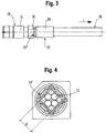
- the illustrated first embodiment of a connector arrangement according to the invention essentially corresponds to the first embodiment, so that reference is made to the above statements.
- the only essential difference is the design of the crimping point 50 '.
- the crimping point 50 ' is arranged between the axial front end 33 of the outer cable conductor 34 and a main body 25 of the outer conductor housing 24, from which the sleeve section protrudes in the longitudinal direction of the cable.
- a star crimp is provided which has a plurality of flat pressing surfaces, while at the further crimping point 62 there can be a rotationally symmetrical crimp or alternatively or additionally also a flat crimp, which can, however, be less deep than the star crimp of the crimping point 50' .
- the wall of the sleeve section 26 in the area of the star crimp 50 ' is essentially square, whereby material accumulations can be formed at the corners of the square by the pressing process.
- a crimp shape has proven to be particularly advantageous in the case of an inner conductor with four cores in the manner of a star quad arrangement.
- a crimp contour in the form of a high-number equilateral polygon can also be used.
- a flat crimp such as a star crimp can be more gentle on the material than a round crimp in order to produce deep constrictions, since it is smaller overall Press forces have to be applied, since they initially act locally during crimping.
- the “inner diameter” D of the sleeve section 26 at the crimping point 50 ' corresponds to the diameter D of the in Fig. 2 sleeve section 26 shown at the crimping point 50.
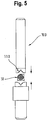
- Fig. 5 is a side view schematically a stamp 100 for producing the crimp 50 'of the connector assembly according to the Figures 3 and 4 shown.
- the connector arrangement 10 is inserted in the correct longitudinal position L between an upper and a lower tool of the plunger 100 and then the upper and lower tools are moved towards one another.
- the press contours 110 of the upper and lower tools form a negative contour of the crimp shape to be produced in the press position.
- the press contours 110 can have recesses provided for receiving material accumulations during the pressing process.
Landscapes
- Coupling Device And Connection With Printed Circuit (AREA)
- Details Of Connecting Devices For Male And Female Coupling (AREA)
Applications Claiming Priority (2)
| Application Number | Priority Date | Filing Date | Title |
|---|---|---|---|
| DE201520000751 DE202015000751U1 (de) | 2015-01-30 | 2015-01-30 | Steckverbinderanordnung mit Kompensationscrimp |
| PCT/EP2016/000132 WO2016120012A1 (de) | 2015-01-30 | 2016-01-26 | Steckverbinderanordnung mit kompensationscrimp |
Publications (2)
| Publication Number | Publication Date |
|---|---|
| EP3251174A1 EP3251174A1 (de) | 2017-12-06 |
| EP3251174B1 true EP3251174B1 (de) | 2020-04-15 |
Family
ID=52738465
Family Applications (1)
| Application Number | Title | Priority Date | Filing Date |
|---|---|---|---|
| EP16701569.2A Active EP3251174B1 (de) | 2015-01-30 | 2016-01-26 | Steckverbinderanordnung mit kompensationscrimp |
Country Status (8)
| Country | Link |
|---|---|
| US (1) | US10367311B2 (zh) |
| EP (1) | EP3251174B1 (zh) |
| JP (1) | JP2018505528A (zh) |
| KR (1) | KR20170106978A (zh) |
| CN (1) | CN107210544B (zh) |
| CA (1) | CA2974043A1 (zh) |
| DE (1) | DE202015000751U1 (zh) |
| WO (1) | WO2016120012A1 (zh) |
Families Citing this family (15)
| Publication number | Priority date | Publication date | Assignee | Title |
|---|---|---|---|---|
| DE102015004485B4 (de) | 2015-04-07 | 2016-12-15 | Rosenberger Hochfrequenztechnik Gmbh & Co. Kg | Verfahren zum Herstellen einer Steckverbinderanordnung |
| HUE045125T2 (hu) | 2016-05-04 | 2019-12-30 | Md Elektronik Gmbh | Kábel |
| DE102017006767B4 (de) * | 2017-07-15 | 2019-10-02 | Rosenberger Hochfrequenztechnik Gmbh & Co. Kg | Steckverbinderanordnung |
| DE102018104253B4 (de) * | 2018-02-26 | 2019-12-05 | Rosenberger Hochfrequenztechnik Gmbh & Co. Kg | Steckverbinderanordnung |
| US10355379B1 (en) * | 2018-03-26 | 2019-07-16 | Delphi Technologies, Llc | Conductor assembly with a crimped tubular ferrule and method of manufacturing same |
| JP7164322B2 (ja) * | 2018-05-18 | 2022-11-01 | キヤノンプレシジョン株式会社 | ケーブルの固定構造およびケーブルの固定方法 |
| DE102018112530A1 (de) * | 2018-05-25 | 2019-11-28 | Rosenberger Hochfrequenztechnik Gmbh & Co. Kg | Steckverbinderanordnung |
| JP7305329B2 (ja) * | 2018-10-12 | 2023-07-10 | ヒロセ電機株式会社 | ケーブルコネクタ |
| DE102018127578A1 (de) * | 2018-11-06 | 2020-05-07 | Rosenberger Hochfrequenztechnik Gmbh & Co. Kg | Kabelanordnung |
| JP7103204B2 (ja) | 2018-12-21 | 2022-07-20 | 株式会社オートネットワーク技術研究所 | コネクタ構造体 |
| US20220139612A1 (en) * | 2019-03-27 | 2022-05-05 | Mitsubishi Electric Corporation | Stationary Induction Apparatus |
| EP3872937B1 (de) * | 2020-02-28 | 2022-02-23 | Rosenberger Hochfrequenztechnik GmbH & Co. KG | Elektrischer steckverbinder und verfahren zur herstellung eines elektrischen steckverbinders |
| JP7435338B2 (ja) * | 2020-07-27 | 2024-02-21 | 住友電装株式会社 | シールド電線の端末構造およびスリーブ |
| JP7232290B2 (ja) * | 2021-07-20 | 2023-03-02 | 日本航空電子工業株式会社 | コンタクト、コネクタ及びケーブル組立体 |
| CN115942620B (zh) * | 2023-01-09 | 2023-08-29 | 广州诺顶智能科技有限公司 | 一种压接机控制方法、系统、压接机及可读介质 |
Citations (1)
| Publication number | Priority date | Publication date | Assignee | Title |
|---|---|---|---|---|
| JP2001155822A (ja) * | 1999-11-29 | 2001-06-08 | Yazaki Corp | シールドコネクタ |
Family Cites Families (31)
| Publication number | Priority date | Publication date | Assignee | Title |
|---|---|---|---|---|
| US2279794A (en) * | 1941-01-08 | 1942-04-14 | Belden Mfg Co | Electrical connector |
| US2769965A (en) * | 1956-03-07 | 1956-11-06 | Thomas & Betts Corp | Nylon-jacketed connector |
| US2970184A (en) | 1958-03-05 | 1961-01-31 | Blonder Tongue Elect | Electric cable connector |
| US3295094A (en) * | 1966-05-10 | 1966-12-27 | Amp Inc | Coaxial plug terminal |
| US4010538A (en) * | 1975-07-01 | 1977-03-08 | Amp Incorporated | Phono plug |
| US4269469A (en) * | 1978-04-21 | 1981-05-26 | Souriau & Cie | Contact terminal connector |
| DE3427361C1 (de) | 1984-07-25 | 1985-09-12 | Wolfgang Dipl.-Ing. 2351 Trappenkamp Freitag | Verbindung zwischen einem koaxialen Steckverbinder und einem Koaxialkabel |
| US5123864A (en) * | 1991-04-05 | 1992-06-23 | Amp Incorporated | Coaxial contact with sleeve |
| US5207596A (en) * | 1992-03-19 | 1993-05-04 | Tandy Corporation | Solderless coaxial wire connector and method for attachment |
| US5480325A (en) | 1994-05-27 | 1996-01-02 | Tandy Corporation | Coaxial connector plug and method for assembly |
| US6107572A (en) * | 1994-07-29 | 2000-08-22 | Sumitomo Wiring Systems, Ltd. | Terminal-processed structure of shielded cable and terminal-processing method of the same |
| DE29515027U1 (de) | 1995-09-19 | 1997-01-30 | Siemens Ag | Elektrisches Kabel mit Kabelschirm |
| JP3731791B2 (ja) * | 1998-11-17 | 2006-01-05 | 矢崎総業株式会社 | 同軸ケーブル用コネクタとその製造方法 |
| JP2002218621A (ja) * | 2001-01-17 | 2002-08-02 | Yazaki Corp | シールド電線の端末処理構造 |
| WO2002103854A2 (en) * | 2001-06-20 | 2002-12-27 | Philip Head | Conductor system |
| TW542456U (en) | 2001-11-02 | 2003-07-11 | Hon Hai Prec Ind Co Ltd | Cable connector |
| JP4606932B2 (ja) | 2005-04-22 | 2011-01-05 | 矢崎総業株式会社 | 同軸ケーブル、同軸ケーブルの端末処理構造、及び、同軸ケーブル用シールド端子 |
| JP5033660B2 (ja) * | 2008-01-30 | 2012-09-26 | 矢崎総業株式会社 | 同軸コネクタ及び同軸コネクタの組み付け方法 |
| JP5826995B2 (ja) * | 2010-08-20 | 2015-12-02 | 矢崎総業株式会社 | シールド電線の端末構造及び端末処理方法 |
| JP2012221661A (ja) * | 2011-04-06 | 2012-11-12 | Yazaki Corp | 同軸ケーブル用のシールド端子 |
| EP2523275B1 (de) | 2011-05-11 | 2013-08-21 | MD Elektronik GmbH | Geschirmtes Kabel und Vorrichtung zum Herstellen eines derartigen Kabels |
| US8827744B2 (en) * | 2011-07-29 | 2014-09-09 | Delphi Technologies, Inc. | Wire cable assembly |
| GB2505453A (en) * | 2012-08-30 | 2014-03-05 | Siemens Plc | Underwater connecting apparatus |
| CN104364980B (zh) * | 2013-02-24 | 2017-04-12 | 古河电气工业株式会社 | 电线连接结构体的制造方法和电线连接结构体 |
| JP6168416B2 (ja) * | 2014-05-28 | 2017-07-26 | 株式会社オートネットワーク技術研究所 | 端子金具付きシールド電線 |
| EP2980937B1 (de) * | 2014-07-30 | 2016-10-12 | MD Elektronik GmbH | Verfahren und Vorrichtung zum Herstellen eines geschirmten Kabels sowie ein geschirmtes Kabel |
| DE202015000750U1 (de) * | 2015-01-30 | 2015-02-25 | Rosenberger Hochfrequenztechnik Gmbh & Co. Kg | Steckverbinderanordnung mit Kompensationshülse |
| DE102015004485B4 (de) * | 2015-04-07 | 2016-12-15 | Rosenberger Hochfrequenztechnik Gmbh & Co. Kg | Verfahren zum Herstellen einer Steckverbinderanordnung |
| US20170215307A1 (en) * | 2016-01-27 | 2017-07-27 | Delphi Technologies, Inc. | Shielded Cable Terminal Assembly |
| JP6734767B2 (ja) * | 2016-11-30 | 2020-08-05 | 日本航空電子工業株式会社 | コネクタ |
| JP6464133B2 (ja) * | 2016-12-20 | 2019-02-06 | 矢崎総業株式会社 | 端子圧着構造及びケーブル付きコネクタ |
-
2015
- 2015-01-30 DE DE201520000751 patent/DE202015000751U1/de not_active Expired - Lifetime
-
2016
- 2016-01-26 CA CA2974043A patent/CA2974043A1/en not_active Abandoned
- 2016-01-26 JP JP2017540176A patent/JP2018505528A/ja active Pending
- 2016-01-26 US US15/547,087 patent/US10367311B2/en active Active
- 2016-01-26 CN CN201680007938.3A patent/CN107210544B/zh active Active
- 2016-01-26 EP EP16701569.2A patent/EP3251174B1/de active Active
- 2016-01-26 WO PCT/EP2016/000132 patent/WO2016120012A1/de active Application Filing
- 2016-01-26 KR KR1020177021166A patent/KR20170106978A/ko unknown
Patent Citations (1)
| Publication number | Priority date | Publication date | Assignee | Title |
|---|---|---|---|---|
| JP2001155822A (ja) * | 1999-11-29 | 2001-06-08 | Yazaki Corp | シールドコネクタ |
Also Published As
| Publication number | Publication date |
|---|---|
| US10367311B2 (en) | 2019-07-30 |
| JP2018505528A (ja) | 2018-02-22 |
| CN107210544B (zh) | 2020-09-04 |
| DE202015000751U1 (de) | 2015-03-06 |
| CA2974043A1 (en) | 2016-08-04 |
| CN107210544A (zh) | 2017-09-26 |
| US20180013241A1 (en) | 2018-01-11 |
| KR20170106978A (ko) | 2017-09-22 |
| EP3251174A1 (de) | 2017-12-06 |
| WO2016120012A1 (de) | 2016-08-04 |
Similar Documents
| Publication | Publication Date | Title |
|---|---|---|
| EP3251174B1 (de) | Steckverbinderanordnung mit kompensationscrimp | |
| EP3251180B1 (de) | Steckverbinderanordnung mit kompensationshülse | |
| EP3251173B1 (de) | Steckverbinderanordnung mit hülsenteil | |
| EP3281260B1 (de) | Verfahren zum herstellen einer steckverbinderanordnung | |
| EP3420612B1 (de) | Elektrischer steckverbinder | |
| EP3537549B1 (de) | Steckverbinderanordnung | |
| EP2523275B1 (de) | Geschirmtes Kabel und Vorrichtung zum Herstellen eines derartigen Kabels | |
| EP3396791B1 (de) | Aussenleiteranordnung | |
| EP3091613B1 (de) | Anschlussverbindung mit einem hf-leiter, insbesondere für ein koaxialkabel und verfahren zur herstellung dieser anschlussverbindung | |
| DE102016006598A1 (de) | Steckverbinder | |
| EP1965467A1 (de) | Hochstrom-Steckkontakt sowie Hochstrom-Steckvorrichtung | |
| EP3021420B1 (de) | Mehradriges geschirmtes Kabel und Verfahren zur Herstellung eines derartigen Kabels | |
| EP4010949B1 (de) | Elektrischer steckverbinder | |
| EP3837741B1 (de) | Kabelanordnung | |
| EP3352311A1 (de) | Steckverbinder und verfahren zur herstellung eines steckverbinders | |
| EP3528351A1 (de) | Elektrischer steckverbinder für ein mehradriges elektrisches kabel | |
| EP1683235A1 (de) | Koaxialkabel und verfahren zu dessen herstellung | |
| DE102011077885B4 (de) | Leitung sowie Verfahren zur Konfektionierung einer derartigen Leitung | |
| DE4300243C1 (de) | Koaxialer 7/16-Buchsensteckverbinder | |
| DE102021112505A1 (de) | Crimpkontakt, Crimpverbindung und Verfahren zur Herstellung einer Crimpverbindung | |
| EP2993737B1 (de) | Hochfrequenz-steckverbindungseinrichtung, insbesondere koaxial-steckverbindungseinrichtung für antennensteckdosen | |
| EP1811613A1 (de) | Kuppler, insbesondere Winkelkuppler nach dem Fakra-Standard, für fahrzeugtechnische Anwendungen | |
| LU500419B1 (de) | Verbindungsanordnung mit Crimpverbindung und Verfahren zur Herstellung einer Verbindungsanordnung mit Crimpverbindung | |
| DE102019134564B4 (de) | Buchsenkontakt | |
| DE102021117926A1 (de) | Verbindungsanordnung mit Crimpverbindung und Verfahren zur Herstellung einer Verbindungsanordnung mit Crimpverbindung |
Legal Events
| Date | Code | Title | Description |
|---|---|---|---|
| STAA | Information on the status of an ep patent application or granted ep patent |
Free format text: STATUS: THE INTERNATIONAL PUBLICATION HAS BEEN MADE |
|
| PUAI | Public reference made under article 153(3) epc to a published international application that has entered the european phase |
Free format text: ORIGINAL CODE: 0009012 |
|
| STAA | Information on the status of an ep patent application or granted ep patent |
Free format text: STATUS: REQUEST FOR EXAMINATION WAS MADE |
|
| 17P | Request for examination filed |
Effective date: 20170727 |
|
| AK | Designated contracting states |
Kind code of ref document: A1 Designated state(s): AL AT BE BG CH CY CZ DE DK EE ES FI FR GB GR HR HU IE IS IT LI LT LU LV MC MK MT NL NO PL PT RO RS SE SI SK SM TR |
|
| AX | Request for extension of the european patent |
Extension state: BA ME |
|
| DAV | Request for validation of the european patent (deleted) | ||
| DAX | Request for extension of the european patent (deleted) | ||
| GRAP | Despatch of communication of intention to grant a patent |
Free format text: ORIGINAL CODE: EPIDOSNIGR1 |
|
| STAA | Information on the status of an ep patent application or granted ep patent |
Free format text: STATUS: GRANT OF PATENT IS INTENDED |
|
| INTG | Intention to grant announced |
Effective date: 20191202 |
|
| GRAS | Grant fee paid |
Free format text: ORIGINAL CODE: EPIDOSNIGR3 |
|
| GRAA | (expected) grant |
Free format text: ORIGINAL CODE: 0009210 |
|
| STAA | Information on the status of an ep patent application or granted ep patent |
Free format text: STATUS: THE PATENT HAS BEEN GRANTED |
|
| AK | Designated contracting states |
Kind code of ref document: B1 Designated state(s): AL AT BE BG CH CY CZ DE DK EE ES FI FR GB GR HR HU IE IS IT LI LT LU LV MC MK MT NL NO PL PT RO RS SE SI SK SM TR |
|
| REG | Reference to a national code |
Ref country code: CH Ref legal event code: EP |
|
| REG | Reference to a national code |
Ref country code: DE Ref legal event code: R096 Ref document number: 502016009543 Country of ref document: DE |
|
| REG | Reference to a national code |
Ref country code: IE Ref legal event code: FG4D Free format text: LANGUAGE OF EP DOCUMENT: GERMAN |
|
| REG | Reference to a national code |
Ref country code: AT Ref legal event code: REF Ref document number: 1258383 Country of ref document: AT Kind code of ref document: T Effective date: 20200515 |
|
| REG | Reference to a national code |
Ref country code: SE Ref legal event code: TRGR |
|
| REG | Reference to a national code |
Ref country code: NL Ref legal event code: MP Effective date: 20200415 |
|
| REG | Reference to a national code |
Ref country code: LT Ref legal event code: MG4D |
|
| PG25 | Lapsed in a contracting state [announced via postgrant information from national office to epo] |
Ref country code: IS Free format text: LAPSE BECAUSE OF FAILURE TO SUBMIT A TRANSLATION OF THE DESCRIPTION OR TO PAY THE FEE WITHIN THE PRESCRIBED TIME-LIMIT Effective date: 20200815 Ref country code: NO Free format text: LAPSE BECAUSE OF FAILURE TO SUBMIT A TRANSLATION OF THE DESCRIPTION OR TO PAY THE FEE WITHIN THE PRESCRIBED TIME-LIMIT Effective date: 20200715 Ref country code: FI Free format text: LAPSE BECAUSE OF FAILURE TO SUBMIT A TRANSLATION OF THE DESCRIPTION OR TO PAY THE FEE WITHIN THE PRESCRIBED TIME-LIMIT Effective date: 20200415 Ref country code: GR Free format text: LAPSE BECAUSE OF FAILURE TO SUBMIT A TRANSLATION OF THE DESCRIPTION OR TO PAY THE FEE WITHIN THE PRESCRIBED TIME-LIMIT Effective date: 20200716 Ref country code: NL Free format text: LAPSE BECAUSE OF FAILURE TO SUBMIT A TRANSLATION OF THE DESCRIPTION OR TO PAY THE FEE WITHIN THE PRESCRIBED TIME-LIMIT Effective date: 20200415 Ref country code: PT Free format text: LAPSE BECAUSE OF FAILURE TO SUBMIT A TRANSLATION OF THE DESCRIPTION OR TO PAY THE FEE WITHIN THE PRESCRIBED TIME-LIMIT Effective date: 20200817 Ref country code: LT Free format text: LAPSE BECAUSE OF FAILURE TO SUBMIT A TRANSLATION OF THE DESCRIPTION OR TO PAY THE FEE WITHIN THE PRESCRIBED TIME-LIMIT Effective date: 20200415 |
|
| PG25 | Lapsed in a contracting state [announced via postgrant information from national office to epo] |
Ref country code: LV Free format text: LAPSE BECAUSE OF FAILURE TO SUBMIT A TRANSLATION OF THE DESCRIPTION OR TO PAY THE FEE WITHIN THE PRESCRIBED TIME-LIMIT Effective date: 20200415 Ref country code: RS Free format text: LAPSE BECAUSE OF FAILURE TO SUBMIT A TRANSLATION OF THE DESCRIPTION OR TO PAY THE FEE WITHIN THE PRESCRIBED TIME-LIMIT Effective date: 20200415 Ref country code: HR Free format text: LAPSE BECAUSE OF FAILURE TO SUBMIT A TRANSLATION OF THE DESCRIPTION OR TO PAY THE FEE WITHIN THE PRESCRIBED TIME-LIMIT Effective date: 20200415 Ref country code: BG Free format text: LAPSE BECAUSE OF FAILURE TO SUBMIT A TRANSLATION OF THE DESCRIPTION OR TO PAY THE FEE WITHIN THE PRESCRIBED TIME-LIMIT Effective date: 20200715 |
|
| PG25 | Lapsed in a contracting state [announced via postgrant information from national office to epo] |
Ref country code: AL Free format text: LAPSE BECAUSE OF FAILURE TO SUBMIT A TRANSLATION OF THE DESCRIPTION OR TO PAY THE FEE WITHIN THE PRESCRIBED TIME-LIMIT Effective date: 20200415 |
|
| REG | Reference to a national code |
Ref country code: DE Ref legal event code: R097 Ref document number: 502016009543 Country of ref document: DE |
|
| PG25 | Lapsed in a contracting state [announced via postgrant information from national office to epo] |
Ref country code: RO Free format text: LAPSE BECAUSE OF FAILURE TO SUBMIT A TRANSLATION OF THE DESCRIPTION OR TO PAY THE FEE WITHIN THE PRESCRIBED TIME-LIMIT Effective date: 20200415 Ref country code: CZ Free format text: LAPSE BECAUSE OF FAILURE TO SUBMIT A TRANSLATION OF THE DESCRIPTION OR TO PAY THE FEE WITHIN THE PRESCRIBED TIME-LIMIT Effective date: 20200415 Ref country code: ES Free format text: LAPSE BECAUSE OF FAILURE TO SUBMIT A TRANSLATION OF THE DESCRIPTION OR TO PAY THE FEE WITHIN THE PRESCRIBED TIME-LIMIT Effective date: 20200415 Ref country code: SM Free format text: LAPSE BECAUSE OF FAILURE TO SUBMIT A TRANSLATION OF THE DESCRIPTION OR TO PAY THE FEE WITHIN THE PRESCRIBED TIME-LIMIT Effective date: 20200415 Ref country code: EE Free format text: LAPSE BECAUSE OF FAILURE TO SUBMIT A TRANSLATION OF THE DESCRIPTION OR TO PAY THE FEE WITHIN THE PRESCRIBED TIME-LIMIT Effective date: 20200415 Ref country code: DK Free format text: LAPSE BECAUSE OF FAILURE TO SUBMIT A TRANSLATION OF THE DESCRIPTION OR TO PAY THE FEE WITHIN THE PRESCRIBED TIME-LIMIT Effective date: 20200415 |
|
| PLBE | No opposition filed within time limit |
Free format text: ORIGINAL CODE: 0009261 |
|
| STAA | Information on the status of an ep patent application or granted ep patent |
Free format text: STATUS: NO OPPOSITION FILED WITHIN TIME LIMIT |
|
| PG25 | Lapsed in a contracting state [announced via postgrant information from national office to epo] |
Ref country code: PL Free format text: LAPSE BECAUSE OF FAILURE TO SUBMIT A TRANSLATION OF THE DESCRIPTION OR TO PAY THE FEE WITHIN THE PRESCRIBED TIME-LIMIT Effective date: 20200415 Ref country code: SK Free format text: LAPSE BECAUSE OF FAILURE TO SUBMIT A TRANSLATION OF THE DESCRIPTION OR TO PAY THE FEE WITHIN THE PRESCRIBED TIME-LIMIT Effective date: 20200415 |
|
| 26N | No opposition filed |
Effective date: 20210118 |
|
| PG25 | Lapsed in a contracting state [announced via postgrant information from national office to epo] |
Ref country code: SI Free format text: LAPSE BECAUSE OF FAILURE TO SUBMIT A TRANSLATION OF THE DESCRIPTION OR TO PAY THE FEE WITHIN THE PRESCRIBED TIME-LIMIT Effective date: 20200415 |
|
| PG25 | Lapsed in a contracting state [announced via postgrant information from national office to epo] |
Ref country code: MC Free format text: LAPSE BECAUSE OF FAILURE TO SUBMIT A TRANSLATION OF THE DESCRIPTION OR TO PAY THE FEE WITHIN THE PRESCRIBED TIME-LIMIT Effective date: 20200415 |
|
| REG | Reference to a national code |
Ref country code: CH Ref legal event code: PL |
|
| PG25 | Lapsed in a contracting state [announced via postgrant information from national office to epo] |
Ref country code: LU Free format text: LAPSE BECAUSE OF NON-PAYMENT OF DUE FEES Effective date: 20210126 |
|
| REG | Reference to a national code |
Ref country code: BE Ref legal event code: MM Effective date: 20210131 |
|
| PG25 | Lapsed in a contracting state [announced via postgrant information from national office to epo] |
Ref country code: CH Free format text: LAPSE BECAUSE OF NON-PAYMENT OF DUE FEES Effective date: 20210131 Ref country code: LI Free format text: LAPSE BECAUSE OF NON-PAYMENT OF DUE FEES Effective date: 20210131 |
|
| PG25 | Lapsed in a contracting state [announced via postgrant information from national office to epo] |
Ref country code: IE Free format text: LAPSE BECAUSE OF NON-PAYMENT OF DUE FEES Effective date: 20210126 |
|
| REG | Reference to a national code |
Ref country code: AT Ref legal event code: MM01 Ref document number: 1258383 Country of ref document: AT Kind code of ref document: T Effective date: 20210126 |
|
| PG25 | Lapsed in a contracting state [announced via postgrant information from national office to epo] |
Ref country code: AT Free format text: LAPSE BECAUSE OF NON-PAYMENT OF DUE FEES Effective date: 20210126 |
|
| PG25 | Lapsed in a contracting state [announced via postgrant information from national office to epo] |
Ref country code: BE Free format text: LAPSE BECAUSE OF NON-PAYMENT OF DUE FEES Effective date: 20210131 |
|
| PGFP | Annual fee paid to national office [announced via postgrant information from national office to epo] |
Ref country code: FR Payment date: 20230124 Year of fee payment: 8 |
|
| PGFP | Annual fee paid to national office [announced via postgrant information from national office to epo] |
Ref country code: SE Payment date: 20230124 Year of fee payment: 8 Ref country code: IT Payment date: 20230120 Year of fee payment: 8 |
|
| PG25 | Lapsed in a contracting state [announced via postgrant information from national office to epo] |
Ref country code: CY Free format text: LAPSE BECAUSE OF FAILURE TO SUBMIT A TRANSLATION OF THE DESCRIPTION OR TO PAY THE FEE WITHIN THE PRESCRIBED TIME-LIMIT Effective date: 20200415 |
|
| P01 | Opt-out of the competence of the unified patent court (upc) registered |
Effective date: 20230527 |
|
| PG25 | Lapsed in a contracting state [announced via postgrant information from national office to epo] |
Ref country code: HU Free format text: LAPSE BECAUSE OF FAILURE TO SUBMIT A TRANSLATION OF THE DESCRIPTION OR TO PAY THE FEE WITHIN THE PRESCRIBED TIME-LIMIT; INVALID AB INITIO Effective date: 20160126 |
|
| REG | Reference to a national code |
Ref country code: DE Ref legal event code: R082 Ref document number: 502016009543 Country of ref document: DE Representative=s name: KANDLBINDER, MARKUS, DIPL.-PHYS., DE |
|
| PG25 | Lapsed in a contracting state [announced via postgrant information from national office to epo] |
Ref country code: MK Free format text: LAPSE BECAUSE OF FAILURE TO SUBMIT A TRANSLATION OF THE DESCRIPTION OR TO PAY THE FEE WITHIN THE PRESCRIBED TIME-LIMIT Effective date: 20200415 |
|
| PGFP | Annual fee paid to national office [announced via postgrant information from national office to epo] |
Ref country code: DE Payment date: 20240129 Year of fee payment: 9 Ref country code: GB Payment date: 20240123 Year of fee payment: 9 |