EP3251174B1 - Plug arrangement comprising a compensation crimp - Google Patents
Plug arrangement comprising a compensation crimp Download PDFInfo
- Publication number
- EP3251174B1 EP3251174B1 EP16701569.2A EP16701569A EP3251174B1 EP 3251174 B1 EP3251174 B1 EP 3251174B1 EP 16701569 A EP16701569 A EP 16701569A EP 3251174 B1 EP3251174 B1 EP 3251174B1
- Authority
- EP
- European Patent Office
- Prior art keywords
- outer conductor
- cable
- crimping point
- connector
- conductor
- Prior art date
- Legal status (The legal status is an assumption and is not a legal conclusion. Google has not performed a legal analysis and makes no representation as to the accuracy of the status listed.)
- Active
Links
- 239000004020 conductor Substances 0.000 claims description 145
- 238000002788 crimping Methods 0.000 claims description 66
- 238000003825 pressing Methods 0.000 claims description 12
- 239000011888 foil Substances 0.000 claims 1
- 238000009413 insulation Methods 0.000 description 5
- 238000004519 manufacturing process Methods 0.000 description 4
- 230000006978 adaptation Effects 0.000 description 3
- 239000000463 material Substances 0.000 description 3
- 238000000034 method Methods 0.000 description 3
- 230000035508 accumulation Effects 0.000 description 2
- 238000009825 accumulation Methods 0.000 description 2
- 230000013011 mating Effects 0.000 description 2
- 230000005540 biological transmission Effects 0.000 description 1
- 230000001419 dependent effect Effects 0.000 description 1
- 238000011161 development Methods 0.000 description 1
- 230000018109 developmental process Effects 0.000 description 1
- 239000003989 dielectric material Substances 0.000 description 1
- 230000001939 inductive effect Effects 0.000 description 1
- 239000012811 non-conductive material Substances 0.000 description 1
- 230000000284 resting effect Effects 0.000 description 1
- 238000005476 soldering Methods 0.000 description 1
Images

Classifications
-
- H—ELECTRICITY
- H01—ELECTRIC ELEMENTS
- H01R—ELECTRICALLY-CONDUCTIVE CONNECTIONS; STRUCTURAL ASSOCIATIONS OF A PLURALITY OF MUTUALLY-INSULATED ELECTRICAL CONNECTING ELEMENTS; COUPLING DEVICES; CURRENT COLLECTORS
- H01R13/00—Details of coupling devices of the kinds covered by groups H01R12/70 or H01R24/00 - H01R33/00
- H01R13/648—Protective earth or shield arrangements on coupling devices, e.g. anti-static shielding
- H01R13/658—High frequency shielding arrangements, e.g. against EMI [Electro-Magnetic Interference] or EMP [Electro-Magnetic Pulse]
- H01R13/6591—Specific features or arrangements of connection of shield to conductive members
- H01R13/6592—Specific features or arrangements of connection of shield to conductive members the conductive member being a shielded cable
-
- H—ELECTRICITY
- H01—ELECTRIC ELEMENTS
- H01R—ELECTRICALLY-CONDUCTIVE CONNECTIONS; STRUCTURAL ASSOCIATIONS OF A PLURALITY OF MUTUALLY-INSULATED ELECTRICAL CONNECTING ELEMENTS; COUPLING DEVICES; CURRENT COLLECTORS
- H01R13/00—Details of coupling devices of the kinds covered by groups H01R12/70 or H01R24/00 - H01R33/00
- H01R13/648—Protective earth or shield arrangements on coupling devices, e.g. anti-static shielding
- H01R13/658—High frequency shielding arrangements, e.g. against EMI [Electro-Magnetic Interference] or EMP [Electro-Magnetic Pulse]
- H01R13/6591—Specific features or arrangements of connection of shield to conductive members
- H01R13/65912—Specific features or arrangements of connection of shield to conductive members for shielded multiconductor cable
- H01R13/65914—Connection of shield to additional grounding conductors
-
- H—ELECTRICITY
- H01—ELECTRIC ELEMENTS
- H01R—ELECTRICALLY-CONDUCTIVE CONNECTIONS; STRUCTURAL ASSOCIATIONS OF A PLURALITY OF MUTUALLY-INSULATED ELECTRICAL CONNECTING ELEMENTS; COUPLING DEVICES; CURRENT COLLECTORS
- H01R4/00—Electrically-conductive connections between two or more conductive members in direct contact, i.e. touching one another; Means for effecting or maintaining such contact; Electrically-conductive connections having two or more spaced connecting locations for conductors and using contact members penetrating insulation
- H01R4/10—Electrically-conductive connections between two or more conductive members in direct contact, i.e. touching one another; Means for effecting or maintaining such contact; Electrically-conductive connections having two or more spaced connecting locations for conductors and using contact members penetrating insulation effected solely by twisting, wrapping, bending, crimping, or other permanent deformation
- H01R4/18—Electrically-conductive connections between two or more conductive members in direct contact, i.e. touching one another; Means for effecting or maintaining such contact; Electrically-conductive connections having two or more spaced connecting locations for conductors and using contact members penetrating insulation effected solely by twisting, wrapping, bending, crimping, or other permanent deformation by crimping
- H01R4/183—Electrically-conductive connections between two or more conductive members in direct contact, i.e. touching one another; Means for effecting or maintaining such contact; Electrically-conductive connections having two or more spaced connecting locations for conductors and using contact members penetrating insulation effected solely by twisting, wrapping, bending, crimping, or other permanent deformation by crimping for cylindrical elongated bodies, e.g. cables having circular cross-section
-
- H—ELECTRICITY
- H01—ELECTRIC ELEMENTS
- H01R—ELECTRICALLY-CONDUCTIVE CONNECTIONS; STRUCTURAL ASSOCIATIONS OF A PLURALITY OF MUTUALLY-INSULATED ELECTRICAL CONNECTING ELEMENTS; COUPLING DEVICES; CURRENT COLLECTORS
- H01R4/00—Electrically-conductive connections between two or more conductive members in direct contact, i.e. touching one another; Means for effecting or maintaining such contact; Electrically-conductive connections having two or more spaced connecting locations for conductors and using contact members penetrating insulation
- H01R4/10—Electrically-conductive connections between two or more conductive members in direct contact, i.e. touching one another; Means for effecting or maintaining such contact; Electrically-conductive connections having two or more spaced connecting locations for conductors and using contact members penetrating insulation effected solely by twisting, wrapping, bending, crimping, or other permanent deformation
- H01R4/18—Electrically-conductive connections between two or more conductive members in direct contact, i.e. touching one another; Means for effecting or maintaining such contact; Electrically-conductive connections having two or more spaced connecting locations for conductors and using contact members penetrating insulation effected solely by twisting, wrapping, bending, crimping, or other permanent deformation by crimping
- H01R4/20—Electrically-conductive connections between two or more conductive members in direct contact, i.e. touching one another; Means for effecting or maintaining such contact; Electrically-conductive connections having two or more spaced connecting locations for conductors and using contact members penetrating insulation effected solely by twisting, wrapping, bending, crimping, or other permanent deformation by crimping using a crimping sleeve
-
- H—ELECTRICITY
- H01—ELECTRIC ELEMENTS
- H01R—ELECTRICALLY-CONDUCTIVE CONNECTIONS; STRUCTURAL ASSOCIATIONS OF A PLURALITY OF MUTUALLY-INSULATED ELECTRICAL CONNECTING ELEMENTS; COUPLING DEVICES; CURRENT COLLECTORS
- H01R9/00—Structural associations of a plurality of mutually-insulated electrical connecting elements, e.g. terminal strips or terminal blocks; Terminals or binding posts mounted upon a base or in a case; Bases therefor
- H01R9/03—Connectors arranged to contact a plurality of the conductors of a multiconductor cable, e.g. tapping connections
- H01R9/05—Connectors arranged to contact a plurality of the conductors of a multiconductor cable, e.g. tapping connections for coaxial cables
- H01R9/0518—Connection to outer conductor by crimping or by crimping ferrule
-
- H—ELECTRICITY
- H01—ELECTRIC ELEMENTS
- H01R—ELECTRICALLY-CONDUCTIVE CONNECTIONS; STRUCTURAL ASSOCIATIONS OF A PLURALITY OF MUTUALLY-INSULATED ELECTRICAL CONNECTING ELEMENTS; COUPLING DEVICES; CURRENT COLLECTORS
- H01R13/00—Details of coupling devices of the kinds covered by groups H01R12/70 or H01R24/00 - H01R33/00
- H01R13/646—Details of coupling devices of the kinds covered by groups H01R12/70 or H01R24/00 - H01R33/00 specially adapted for high-frequency, e.g. structures providing an impedance match or phase match
- H01R13/6473—Impedance matching
- H01R13/6474—Impedance matching by variation of conductive properties, e.g. by dimension variations
Landscapes
- Coupling Device And Connection With Printed Circuit (AREA)
- Details Of Connecting Devices For Male And Female Coupling (AREA)
Description
Die Erfindung betrifft eine Steckverbinderanordnung, die aus einem Steckverbinder und einem daran angeschlossenen Kabel besteht. Das Kabel hat mindestens einen Innenleiter und einen den Innenleiter umlaufenden Außenleiter, wobei ein axialer Endabschnitt des Außenleiters elektrisch mit einem diesen umlaufenden Hülsenabschnitt eines Außenleitergehäuses des Steckverbinders verbunden ist.The invention relates to a connector assembly consisting of a connector and a cable connected to it. The cable has at least one inner conductor and an outer conductor encircling the inner conductor, an axial end section of the outer conductor being electrically connected to a sleeve section of an outer conductor housing of the plug connector encircling the latter.
Der Steckverbinder hat ein steckseitiges Ende zum Verbinden des Steckverbinders mit einem Gegensteckverbinder und ein kabelseitiges Ende, an dem das Kabel (vorzugsweise unlösbar durch Löten oder Crimpen) befestigt ist. Dabei ist der Innenleiter des Kabels elektrisch mit einem Innenleiterteil des Steckverbinders wie etwa einem Kontaktstift oder einer Kontaktbuchse verbunden und der Außenleiter des Kabels ist elektrisch mit dem das Innenleiterteil umlaufenden Außenleitergehäuse des Steckverbinders verbunden, so dass vorzugsweise von dem Kabel bis zu dem steckseitigen Ende des Steckverbinders eine durchgehende Schirmung gebildet ist.The connector has a plug end for connecting the connector to a mating connector and a cable end to which the cable is attached (preferably inseparably by soldering or crimping). The inner conductor of the cable is electrically connected to an inner conductor part of the connector, such as a contact pin or a contact socket, and the outer conductor of the cable is electrically connected to the outer conductor housing of the connector surrounding the inner conductor part, so that preferably from the cable to the plug-side end of the connector continuous shielding is formed.
Es ist bekannt, zum Herstellen der Verbindung zwischen dem Steckverbinder und dem Kabel den aus einem elektrisch leitenden Material bestehenden und den Endabschnitt des Außenleiters umlaufenden Hülsenabschnitt des Außenleitergehäuses mit dem axialen Endabschnitt des Außenleiters zu vercrimpen bzw. zu verpressen. Dazu wird bei der Herstellung der Steckverbinderanordnung das Kabel an seinem vorderen Ende abisoliert bzw. der Kabelmantel abschnittsweise entfernt, so dass der Außenleiter freigelegt ist. Anschließend wird der Hülsenabschnitt des Außenleitergehäuses mit dem freigelegten Außenleiter verpresst.It is known for crimping or crimping the sleeve section of the outer conductor housing, which consists of an electrically conductive material and encircling the end section of the outer conductor, to the axial end section of the outer conductor in order to establish the connection between the connector and the cable. This will during the manufacture of the connector arrangement, the cable is stripped at its front end or the cable sheath is removed in sections so that the outer conductor is exposed. The sleeve section of the outer conductor housing is then pressed together with the exposed outer conductor.
Es hat sich allerdings herausgestellt, dass eine auf die beschriebene herkömmliche Art hergestellte Steckverbinderanordnung im Bereich der Verbindung zwischen dem Steckverbinder und dem Kabel regelmäßig nicht optimal elektrisch angepasst ist. Insbesondere kann es im Verbindungsbereich zu ungewollten Abweichungen von dem vorgesehenen Wellenwiderstand wie etwa zu einem unerwünschten Impedanzanstieg kommen.However, it has been found that a connector arrangement produced in the conventional manner described is generally not optimally adapted electrically in the region of the connection between the connector and the cable. In particular, undesired deviations from the intended characteristic impedance, such as an undesirable increase in impedance, can occur in the connection area.
Die Druckschriften
In Anbetracht der beschriebenen Probleme ist es die Aufgabe der vorliegenden Erfindung, eine stabil und zugfest eingerichtete Verbindung zwischen dem Steckverbinder und dem Kabel bereitzustellen, die ferner möglichst über ihre gesamte Erstreckung in Kabellängsrichtung optimal elektrisch angepasst ist.In view of the problems described, it is the object of the present invention to provide a stable and tensile connection between the connector and the cable, which is also optimally electrically adapted over its entire extent in the longitudinal direction of the cable.
Diese Aufgabe wird durch eine Steckverbinderanordnung gemäß Anspruch 1 gelöst. Vorteilhafte Weiterbildungen der Erfindung sind in den abhängigen Ansprüchen beschrieben.This object is achieved by a connector arrangement according to claim 1. Advantageous developments of the invention are described in the dependent claims.
Die erfindungsgemäße Steckverbinderanordnung weist eine Crimpstelle mit einer radialen Verengung des Hülsenabschnitts auf, die in der Kabellängsrichtung zwischen dem axialen Endabschnitt des Außenleiters und dem axialen Ende des Innenleiters angeordnet ist. Vorzugsweise wird die Crimpstelle durch eine von radial außen auf den Hülsenabschnitt des Außenleitergehäuses einwirkende Presskraft im Bereich zwischen dem vorderen axialen Ende des Außenleiters und dem steckseitigen Ende des Hülsenabschnitts hergestellt. Diese Presskraft wird dabei vorzugsweise ringsum aufgebracht, so dass die radiale Verengung des Hülsenabschnitts den Innenleiter vollständig umläuft. Dadurch ist der radiale Abstand zwischen dem Hülsenabschnitt und dem Innenleiter im Bereich der radialen Verengung geringer als im übrigen Bereich des Hülsenabschnitts, der die radiale Verengung nicht aufweist.The connector arrangement according to the invention has a crimping point with a radial narrowing of the sleeve section, which is arranged in the longitudinal direction of the cable between the axial end section of the outer conductor and the axial end of the inner conductor. The crimping point is preferably produced by a pressing force acting radially on the outside of the sleeve section of the outer conductor housing in the region between the front axial end of the outer conductor and the plug-side end of the sleeve section. This pressing force is preferably applied all around, so that the radial narrowing of the sleeve section completely surrounds the inner conductor. This is the radial distance between the sleeve section and the inner conductor in the area of the radial narrowing is less than in the rest of the area of the sleeve section which does not have the radial narrowing.
Die Erfindung geht auf die Erkenntnis zurück, dass zum Erhalt einer in Kabellängsrichtung gleichbleibenden Impedanz bei unveränderter Kabelgeometrie und gleichen Dielektrika auch ein im Wesentlichen gleichbleibender Abstand zwischen dem Innenleiter und dem Außenleiter des Kabels erforderlich ist. So führt eine Vergrößerung des Abstands zwischen Innenleiter und Außenleiter des Kabels regelmäßig zu einem induktiven Bereich bzw. zu einem ungewollten Impedanzanstieg. Eine unerwünschte sprunghafte Änderung des Abstands zwischen dem Innenleiter und dem Außenleiter (bzw. der Abschirmung des Innenleiters) liegt bei herkömmlichen Steckverbinderanordnungen regelmäßig an dem vorderen axialen Ende des Außenleiters vor. Erfindungsgemäß wird dagegen durch die radiale Verengung des Hülsenabschnitts in demjenigen Bereich des Kabels an dessen vorderem Ende, in dem kein Kabelaußenleiter den Innenleiter umläuft, die Größe dieses Sprungs zwischen Innenleiter und Abschirmung verringert, da der aus einem leitenden Material bestehende Hülsenabschnitt durch die Presskraft näher an den Innenleiter herangeführt wird, so dass der verengte Hülsenabschnitt den Außenleiter des Kabels über das Ende des eigentlichen Außenleiters hinaus in Richtung auf den Steckverbinder fortsetzt.The invention is based on the knowledge that an essentially constant distance between the inner conductor and the outer conductor of the cable is also required in order to maintain an impedance that is constant in the longitudinal direction of the cable with unchanged cable geometry and the same dielectrics. An increase in the distance between the inner conductor and outer conductor of the cable regularly leads to an inductive area or to an undesired increase in impedance. In conventional connector arrangements, an undesirable abrupt change in the distance between the inner conductor and the outer conductor (or the shielding of the inner conductor) is regularly present at the front axial end of the outer conductor. In contrast, according to the invention, the radial narrowing of the sleeve section in that area of the cable at its front end in which no outer cable conductor runs around the inner conductor reduces the size of this jump between the inner conductor and the shield, since the sleeve section, which consists of a conductive material, is brought closer by the pressing force the inner conductor is brought up so that the narrowed sleeve section continues the outer conductor of the cable beyond the end of the actual outer conductor in the direction of the connector.
Vorteilhafterweise ist die Crimpstelle unmittelbar an den axialen Endabschnitt bzw. an das vordere axiale Ende des Außenleiters angrenzend angeordnet, wobei der Abstand zwischen der Crimpstelle und dem axialen Endabschnitt bevorzugt kleiner ist als 2 mm, insbesondere kleiner ist als 0,5 mm. Mit anderen Worten ist die Verengung des Hülsenabschnitts unmittelbar benachbart an das axiale Ende des Außenleiters angeordnet, um in diesem Bereich eine lokale Impedanzänderung zuverlässig zu vermeiden.The crimping point is advantageously arranged directly adjacent to the axial end section or to the front axial end of the outer conductor, the distance between the crimping point and the axial end section preferably being less than 2 mm, in particular less than 0.5 mm. In other words, the narrowing of the sleeve section is arranged immediately adjacent to the axial end of the outer conductor in order to reliably avoid a local change in impedance in this area.
Die Tiefe der radialen Verengung ist derart eingerichtet, dass der Innendurchmesser des Hülsenabschnitts an der Crimpstelle im Wesentlichen demjenigen des Außenleiters des Kabels entspricht, so dass der verengte Hülsenabschnitt des Außenleitergehäuses den Außenleiter in Richtung auf das vordere Kabelende unter konstantem Abstand zu dem Innenleiter praktisch fortsetzt.The depth of the radial narrowing is set up in such a way that the inner diameter of the sleeve section at the crimping point essentially corresponds to that of the outer conductor of the cable, so that the narrowed sleeve section of the outer conductor housing practically continues the outer conductor in the direction of the front cable end at a constant distance from the inner conductor.
Dabei liegt das Verhältnis zwischen dem Innendurchmesser des Hülsenabschnitts an der tiefsten Stelle der Verengung und dem Innendurchmesser des Außenleiters zwischen 0,9 und 1,2, bevorzugt zwischen 0,95 und 1,1, insbesondere zwischen 0,98 und 1,05, so dass der Außenleiter an seinem axialen vorderen Ende praktisch nahtlos in den Hülsenabschnitt übergeht. Ein Sprung des Abstands zwischen Innenleiter und dessen Schirmung am vorderen Ende des Außenleiters wird auf diese Weise zuverlässig verhindert.The ratio between the inner diameter of the sleeve section at the deepest point of the constriction and the inner diameter of the outer conductor is between 0.9 and 1.2, preferably between 0.95 and 1.1, in particular between 0.98 and 1.05, so that the outer conductor merges seamlessly into the sleeve section at its axial front end. A jump in the distance between the inner conductor and its shielding at the front end of the outer conductor is reliably prevented in this way.
Alternativ oder zusätzlich ist das steckverbinderseitige Ende der Crimpstelle unmittelbar angrenzend an einen Hauptkörper des Außenleitergehäuses angeordnet, von dem ausgehend der Hülsenabschnitt in Kabellängsrichtung vorsteht und der etwa denselben Durchmesser hat wie der Außenleiter des Kabels, wobei der Abstand zwischen der Crimpstelle und dem Hauptkörper bevorzugt kleiner ist als 3 mm, insbesondere kleiner ist als 1 mm, insbesondere etwa 0 mm beträgt.Alternatively or additionally, the connector-side end of the crimping point is arranged directly adjacent to a main body of the outer conductor housing, from which the sleeve section protrudes in the longitudinal direction of the cable and which has approximately the same diameter as the outer conductor of the cable, the distance between the crimping point and the main body preferably being smaller is less than 3 mm, in particular less than 1 mm, in particular approximately 0 mm.
Da der Außenleiter des Kabels regelmäßig auf einem den Innenleiter umgebenden Dielektrikum aufliegt und damit einen wesentlich geringeren Durchmesser hat als der Hülsenabschnitt des Außenleitergehäuses, ist regelmäßig eine besonders hohe radiale Crimpkraft zum Bereitstellen der radialen Verengung in der erforderlichen Tiefe notwendig. Ein (exakt) radialsymmetrischer Crimp mit einer derart großen Tiefe kann problematisch sein, da dadurch unter Umständen der Innenleiter oder der Hülsenabschnitt beschädigt werden können. Aus diesem Grund ist die Crimpstelle mit einem nicht-rotationssymmetrischen Crimp, insbesondere einem nicht-rotationssymmetrischen Isolierungscrimp bereitgestellt (der Hülsenabschnitt ist an der Crimpstelle mit dem Dielektrikum des Kabels und nicht mit dem Außenleiter des Kabels verpresst). Bei einem nicht-rotationssymmetrischer Crimp werden in Umfangsrichtung lokal variierende Radialkräfte aufgebracht, was insgesamt zu einer höheren Maximaltiefe der radialen Verengung führt. Als besonders vorteilhaft hat sich ein in Umfangsrichtung ebene Pressflächen aufweisender Flachcrimp, insbesondere ein Sterncrimp erwiesen.Since the outer conductor of the cable regularly rests on a dielectric surrounding the inner conductor and thus has a significantly smaller diameter than the sleeve section of the outer conductor housing, a particularly high radial crimping force is regularly necessary to provide the radial narrowing at the required depth. An (exactly) radially symmetrical crimp with such a large depth can be problematic, since it can damage the inner conductor or the sleeve section. For this reason, the crimp point is provided with a non-rotationally symmetrical crimp, in particular a non-rotationally symmetrical insulation crimp (the sleeve section is pressed at the crimp point with the dielectric of the cable and not with the outer conductor of the cable). In the case of a non-rotationally symmetrical crimp, locally varying radial forces are applied in the circumferential direction, which overall leads to a greater maximum depth of the radial constriction. A flat crimp, in particular a star crimp, which has flat pressing surfaces in the circumferential direction has proven to be particularly advantageous.
In diesem Zusammenhang hat es sich als besonders vorteilhaft erwiesen, dass der Crimp drei oder mehr, insbesondere vier den Innenleiter umlaufende ebene Pressflächen aufweist. Im Schnitt kann der Hülsenabschnitt damit an der Crimpstelle im Wesentlichen die Außenkontur eines Polygons, insbesondere eines regelmäßigen Polygons haben. In Umfangsrichtung jeweils im Wesentlichen dieselbe Abmessung aufweisende ebene Pressflächen sind nämlich zum einen mittels eines entsprechend geformten (Crimp-)Stempels einfach herstellbar, wobei der Hülsenabschnitt gleichzeitig beim Crimpen im Umfangsrichtung im Wesentlichen gleichmäßig belastet wird. Als besonders vorteilhaft, insbesondere im Falle von vier Innenleitern, die nach Art einer Sternviereranordnung verlaufen können, hat sich eine im Querschnitt im Wesentlichen quadratische Crimpstelle erwiesen.In this context, it has proven to be particularly advantageous that the crimp has three or more, in particular four, flat pressing surfaces encircling the inner conductor. On average, the sleeve section at the crimping point in Essentially have the outer contour of a polygon, especially a regular polygon. In the circumferential direction in each case essentially the same dimension having flat pressing surfaces can be easily produced on the one hand by means of a correspondingly shaped (crimping) stamp, the sleeve section being loaded substantially uniformly during crimping in the circumferential direction. A crimping point which is essentially square in cross-section has proven to be particularly advantageous, in particular in the case of four inner conductors which can run in the manner of a star quad arrangement.
Im Hinblick auf eine optimale elektrische Verbindung zwischen dem Außenleiter und dem Außenleitergehäuse hat es sich als zweckmäßig erwiesen, mindestens eine weitere Crimpstelle auf der dem Steckverbinder abgewandten Seite der (ersten) Crimpstelle vorzusehen, wobei an der weiteren Crimpstelle der Außenleiter des Kabels mit dem Hülsenabschnitt des Steckverbinders verpresst ist. Die weitere Crimpstelle kann unter einem axialen Abstand zu der ersten Crimpstelle angeordnet sein oder diese alternativ zumindest teilweise in axialer Richtung überlappen. Das Bereitstellen von mehr als einer Crimpstelle führt ferner zu einer besonders stabilen und zugfesten Verbindung von Steckverbinder und Kabel. An der ersten Crimpstelle kann ein Isolierungscrimp vorgesehen sein und/oder an der zweiten Stelle ein Leitercrimp.With regard to an optimal electrical connection between the outer conductor and the outer conductor housing, it has proven to be expedient to provide at least one further crimping point on the side of the (first) crimping point facing away from the plug connector, the outer conductor of the cable with the sleeve section of the Connector is pressed. The further crimping point can be arranged at an axial distance from the first crimping point or alternatively at least partially overlap it in the axial direction. The provision of more than one crimp point also leads to a particularly stable and tensile connection of the plug connector and the cable. An insulation crimp can be provided at the first crimp point and / or a conductor crimp at the second point.
Im Hinblick auf eine stabile Halterung des vorderen Kabelendes in dem Hülsenabschnitt unter gleichzeitiger Bereitstellung eines im Wesentlichen konstanten radialen Abstands zwischen dem Innenleiter und dessen Schirmung hat es sich als vorteilhaft erwiesen, dass der Außendurchmesser und/oder der Innendurchmesser des Außenleitergehäuses an der Crimpstelle kleiner ist als an der weiteren Crimpstelle. An der Crimpstelle weist das Kabel nämlich keinen Außenleiter auf, so dass hier eine tiefere radiale Verengung des Hülsenabschnitts erforderlich ist als an der weitere Crimpstelle mit Außenleiter. Mit anderen Worten ist die radiale Verengung des Hülsenabschnitts an der Crimpstelle tiefer als eine an der weiteren Crimpstelle gebildete weitere radiale Verengung des Hülsenabschnitts.With regard to a stable mounting of the front cable end in the sleeve section while simultaneously providing a substantially constant radial distance between the inner conductor and its shielding, it has proven to be advantageous that the outer diameter and / or the inner diameter of the outer conductor housing at the crimping point is smaller than at the other crimp point. This is because the cable has no outer conductor at the crimping point, so that a deeper radial narrowing of the sleeve section is required here than at the further crimping point with the outer conductor. In other words, the radial narrowing of the sleeve section at the crimping point is deeper than a further radial narrowing of the sleeve section formed at the further crimping point.
Das Kabel weist vorzugsweise eine den Innenleiter umlaufende Stützhülse auf der dem Steckverbinder abgewandten Seite der ersten Crimpstelle auf. Vorzugsweise ist der Innendurchmesser der Stützhülse etwas größer als der Außendurchmesser des Außenleiters, so dass die Stützhülse problemlos außen auf den Außenleiter aufbringbar ist. Die Stützhülse dient einer verbesserten Verpressung von Außenleiter und Hülsenabschnitt unter Vermeidung einer Beschädigung der Innenleiter beim Crimpvorgang.The cable preferably has a support sleeve running around the inner conductor on the side of the first crimping point facing away from the connector. The inner diameter of the support sleeve is preferably somewhat larger than the outer diameter of the Outer conductor, so that the support sleeve can be easily attached to the outside of the outer conductor. The support sleeve serves to improve the pressing of the outer conductor and the sleeve section while avoiding damage to the inner conductor during the crimping process.
Während sich die weitere Crimpstelle auf Höhe der Stützhülse befindet, ist die (erste) Crimpstelle in Kabellängsrichtung vorzugsweise zwischen dem steckseitigen Ende der Stützhülse und dem steckseitigen Ende des Hülsenabschnitts angeordnet.While the further crimping point is at the level of the support sleeve, the (first) crimping point in the longitudinal direction of the cable is preferably arranged between the plug-side end of the support sleeve and the plug-side end of the sleeve section.
Die Stützhülse kann zum Halten und Fixieren des vorderen Endes des Außenleiters vorgesehen sein, insbesondere wenn der Außenleiter in Form eines Drahtgeflechts o.dgl. eingerichtet ist. Dazu ist die Stützhülse vorzugsweise radial außen auf dem Außenleiter angeordnet. In diesem Zusammenhang hat es sich als vorteilhaft erwiesen, dass das steckseitige Ende der Stützhülse in Kabellängsrichtung im Wesentlichen mit dem axialen vorderen Ende des Außenleiters zusammenfällt, so dass die Stützhülse den Außenleiter bis hin zu seinem vorderen axialen Ende stützt und hält.The support sleeve can be provided for holding and fixing the front end of the outer conductor, in particular if the outer conductor or the like in the form of a wire mesh. is set up. For this purpose, the support sleeve is preferably arranged radially on the outside on the outer conductor. In this context, it has proven to be advantageous that the plug-side end of the support sleeve essentially coincides with the axial front end of the outer conductor in the longitudinal direction of the cable, so that the support sleeve supports and holds the outer conductor up to its front axial end.
Im Hinblick auf eine optimale elektrische und mechanische Verbindung zwischen dem Außenleiter, der Stützhülse und dem Außenleitergehäuse hat es sich als vorteilhaft erwiesen, dass der Außenleiter um die Stützhülse herum zurückgefaltet ist. In diesem Fall kann durch Verpressung eine besonders dauerhafte und stabile Crimpverbindung zwischen dem vorzugsweise als Drahtgeflecht gebildeten Außenleiter und der Stützhülse bzw. dem Hülsenabschnitt des Außenleitergehäuses hergestellt werden.With regard to an optimal electrical and mechanical connection between the outer conductor, the support sleeve and the outer conductor housing, it has proven to be advantageous that the outer conductor is folded back around the support sleeve. In this case, a particularly permanent and stable crimp connection can be produced between the outer conductor, which is preferably formed as a wire mesh, and the support sleeve or the sleeve section of the outer conductor housing.
Bei einer besonders bevorzugten Ausführungsform der Erfindung ist die Stützhülse zumindest abschnittsweise in Form einer zylindermantelförmigen Hülse wie etwa einer Crimphülse gebildet, die entweder als einzelnes Teil gebildet sein kann oder aus mehreren Zylinderschalenteilen bestehen kann. Der Innendurchmesser der Stützhülse kann an den Außendurchmesser des Außenleiters angepasst sein.In a particularly preferred embodiment of the invention, the support sleeve is formed at least in sections in the form of a cylindrical jacket-shaped sleeve, such as a crimp sleeve, which can either be formed as a single part or can consist of several cylindrical shell parts. The inner diameter of the support sleeve can be adapted to the outer diameter of the outer conductor.
Im Hinblick auf eine kostengünstige Herstellbarkeit und im Hinblick auf ein vergleichsweise leichtes Kabelgewicht hat es sich als vorteilhaft erwiesen, dass der Außenleiter in Form eines Geflechts wie etwa eines Drahtgeflechts gebildet ist. Ein Drahtgeflecht ist ferner besonders gut zum Herstellen einer Pressverbindung geeignet und eignet sich zum Zurückfalten über die Stützhülse.In terms of cost-effective manufacture and in view of a comparatively light cable weight, it has proven to be advantageous for the outer conductor to be in the form of a braid, such as a wire mesh. On Wire mesh is also particularly well suited for producing a press connection and is suitable for folding back over the support sleeve.
Andererseits kann der Innenleiter in Form einer von einem Dielektrikum umgebenen Seele oder eines oder mehrerer jeweils isolierter Adern gebildet sein. Bspw. sind ein oder mehrere Innenleiterpaare zum Übertragen eines oder mehrerer differentieller Signale über das Kabel vorgesehen. Zwei Innenleiterpaare können bspw. in einer Sternviereranordnung verlaufen. Vorzugsweise sind alle Innenleiter von dem gemeinsamen Außenleiter in Form eines Drahtgeflechts umlaufen.On the other hand, the inner conductor can be formed in the form of a core surrounded by a dielectric or one or more respectively insulated cores. E.g. one or more pairs of inner conductors are provided for transmitting one or more differential signals over the cable. For example, two pairs of inner conductors can run in a star quad arrangement. All inner conductors are preferably encircled by the common outer conductor in the form of a wire mesh.
Das Kabel kann ein Koaxialkabel, ein geschirmtes Twisted-Pair-Kabel, ein geschirmtes Stern-Viererkabel o. dgl. sein. Derartige Kabel sind regelmäßig zur Übertragung von HF-Signalen vorgesehen, wobei in diesem Fall eine optimale elektrische Anpassung besonders wichtig ist, um eine Verfälschung des Signalverlaufs zu vermeiden.The cable can be a coaxial cable, a shielded twisted pair cable, a shielded star quad cable or the like. Such cables are regularly provided for the transmission of RF signals, in which case optimal electrical adaptation is particularly important in order to avoid falsification of the signal curve.
In der nun folgenden Beschreibung wird die Erfindung unter Bezugnahme auf die beigefügten Zeichnungen erläutert. Dabei zeigen:
- Fig. 1
- eine teilweise als Längsschnitt dargestellte schematische Seitenansicht einer nicht erfindungsgemäßen Steckverbinderanordnung,
- Fig. 2
- eine teilweise als Ansicht von links dargestellte schematische Schnittansicht der Steckverbinderanordnung aus
Fig. 1 , - Fig. 3
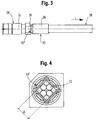
- eine Seitenansicht einer zweiten Ausführungsform einer erfindungsgemäßen Steckverbinderanordnung,
- Fig. 4
- eine Schnittansicht der in
Fig. 3 gezeigten zweiten Ausführungsform von rechts, und - Fig. 5
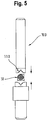
- eine Ansicht eines Crimpstempels zum Herstellen der in den
Figuren 3 und 4 dargestellten Steckverbinderanordnung.
- Fig. 1
- 2 shows a schematic side view, partially as a longitudinal section, of a connector arrangement not according to the invention,
- Fig. 2
- a partial sectional view of the connector assembly shown from the left
Fig. 1 , - Fig. 3
- 2 shows a side view of a second embodiment of a connector arrangement according to the invention,
- Fig. 4
- a sectional view of the in
Fig. 3 shown second embodiment from the right, and - Fig. 5
- a view of a crimp stamp for manufacturing the in the
Figures 3 and 4 connector arrangement shown.
Die in
Der Steckverbinder 20 ist zum Verbinden mit einem Gegensteckverbinder wie etwa einem Buchsenteil an seinem in
Das Kabel 30 weist (hier beispielhaft) insgesamt vier verseilte Innenleiter 32 in Form von jeweils mit einer Isolierung versehenen Adern auf. Jeweils zwei Innenleiter 32 bilden ein differentielles Leiterpaar zu Übertragung differentieller Signale wie etwa HF-Signale o.dgl. Die vier Innenleiter 32 sind von einem gemeinsamen (Kabel-)Außenleiter 34 in Form eines Drahtgeflechts und/oder einer leitenden Folie umgeben, das die Innenleiter 32 nach außen hin abschirmt. Das Drahtgeflecht liegt außen an den Aderisolierungen an. Der Außenleiter 34 ist außen koaxial von einem Kabelmantel 80 aus einem nichtleitenden Material wie etwa einem Kunststoff umgeben.The
Die Innenleiter 32 sind jeweils an ihrem dem Steckverbinder 20 zugewandten vorderen Ende mit Innenleiterkontakten (nicht gezeigt) des Steckverbinders 20 elektrisch verbunden. Der Außenleiter 34 ist an seinem dem Steckverbinder 20 zugewandten vorderen Endabschnitt mit einem Hülsenabschnitt 26 des Außenleitergehäuses 24 des Steckverbinders 20 elektrisch verbunden, wobei das Außenleitergehäuse 24 die Abschirmung der Innenleiter 32 bis hin zu dem steckseitigen Ende des Steckverbinders 20 fortsetzt.The
Das vordere Kabelende ist in dem rohrartigen Hülsenabschnitt 26 des Außenleitergehäuses 24 aufgenommen, der ausgehend von einem Hauptkörper des Außenleitergehäuses 24 kabelseitig vorsteht. Der Innendurchmesser des Hülsenabschnitts 26 entspricht im Wesentlichen dem Außendurchmesser des Kabelmantels 80, so dass das Kabel 30 in die durch den Hülsenabschnitt 26 gebildete Öffnung einführbar ist.The front cable end is received in the
An dem vorderen Ende des Kabels 30 ist der Kabelmantel 80 entfernt, so dass der Außenleiter 34 des Kabels freigelegt ist und in elektrischen Kontakt mit der Wand des Hülsenabschnitts 26 gebracht werden kann.At the front end of the
Zur besseren Fixierung des vorderen axialen Endes 33 des Kabelaußenleiters 34 und insbesondere zum Verhindern einer Beschädigung der Innenleiter 32 bei der Herstellung der weiteren Crimpstelle 62 zwischen dem Kabelaußenleiter 34 und dem Hülsenabschnitt 26 ist eine Stützhülse 60 auf einem vorderen Abschnitt des Außenleiters 34 vorgesehen. Das Drahtgeflecht des Außenleiters 34 ist um das vordere Ende der Stützhülse 60 herum zurückgeschlagen, so dass das Drahtgeflecht des Außenleiters 34 an der Stützhülse 60 innen und außen anliegt. Damit bildet das an dem vorderen Ende der Stützhülse 60 anliegende Drahtgeflecht das vordere axiale Ende 33 des Außenleiters 34.A
Wie in
Wie in
Der in
Die in den
Wie in
In
Claims (11)
- Connector assembly (10) comprising a connector (20) and a cable (30) connected thereto comprising at least one inner conductor (32) and an outer conductor (34) surrounding the inner conductor(s) (32), an axial end portion (33) of the outer conductor (34) being electrically connected to a sleeve portion (26) of an outer conductor housing (24) of the connector (20), which sleeve portion surrounds said outer conductor, wherein a crimping point (50') comprising a radial constriction of the sleeve portion (26), which crimping point is arranged between the axial end portion (33) of the outer conductor (34) and the axial end of the inner conductor (30) in the cable longitudinal direction (L), the crimping point (50') comprising a rotationally asymmetric crimp,
characterised in that
the depth of the radial constriction is designed such that the inner diameter of the sleeve portion (26) at the crimping point (50') substantially corresponds to the diameter of the outer conductor (34) of the cable (30) and the ratio between the inner diameter of the sleeve portion at the deepest point of the constriction and the inner diameter of the outer conductor being between 0.9 and 1.2. - Connector assembly according to claim 1, characterised in that the crimping point (50') is arranged so as to immediately adjoin the axial end portion (33) of the outer conductor (34), the distance between the crimping point (50') and the axial end portion (33) preferably being less than 2 mm, in particular less than 0.5 mm.
- Connector assembly according to at least one of the preceding claims, characterised in that the connector-side end of the crimping point (50') is arranged so as to immediately adjoin a main body (25) of the outer conductor housing (24) that has approximately the same inner diameter as the outer conductor (34) of the cable, the distance between the crimping point (50') and the main body (25) preferably being less than 3 mm, particularly preferably less than 1 mm, in particular approximately 0 mm.
- Connector assembly according to at least one of the preceding claims, characterised in that the crimping point (50') comprises a flat crimp comprising planar pressing surfaces, in particular a star crimp.
- Connector assembly according to claim 4, characterised in that the crimp comprises three or more, in particular four, planar pressing surfaces surrounding the inner conductor and each having substantially the same dimensions in the circumferential direction, the sleeve portion preferably having a substantially square outer contour in cross-section at the crimping point (50').
- Connector assembly according to at least one of the preceding claims, characterised by at least one other crimping point (62) on the side of the crimping point (50') remote from the connector (20), at which other crimping point the outer conductor (34) of the cable is compressed by means of the sleeve portion (26) of the connector.
- Connector assembly according to claim 6, characterised in that the outer diameter of the sleeve portion (26) is less at the crimping point (50') than at the other crimping point (62).
- Connector assembly according to either of claims 6 or 7, characterised by a support sleeve (60) surrounding the inner conductor, for example a crimping sleeve, on the side of the crimping point (50') remote from the connector (20).
- Connector assembly according to claim 8, characterised in that the support sleeve (60) is arranged radially outside on the outer conductor (34), the outer conductor (34) preferably being folded back around the support sleeve (60).
- Connector assembly according to at least one of the preceding claims, characterised in that the outer conductor (34) is in the form of a braid, for example a wire braid, or a conductive foil and/or the inner conductor (32) is in the form of a core surrounded by a dielectric or in the form of one or more individually insulated wires.
- Connector assembly according to at least one of the preceding claims, characterised in that the cable (30) is a coaxial cable, a shielded twisted-pair cable or a shielded star-quad cable.
Applications Claiming Priority (2)
| Application Number | Priority Date | Filing Date | Title |
|---|---|---|---|
| DE201520000751 DE202015000751U1 (en) | 2015-01-30 | 2015-01-30 | Connector assembly with compensation crimp |
| PCT/EP2016/000132 WO2016120012A1 (en) | 2015-01-30 | 2016-01-26 | Plug arrangement comprising a compensation crimp |
Publications (2)
| Publication Number | Publication Date |
|---|---|
| EP3251174A1 EP3251174A1 (en) | 2017-12-06 |
| EP3251174B1 true EP3251174B1 (en) | 2020-04-15 |
Family
ID=52738465
Family Applications (1)
| Application Number | Title | Priority Date | Filing Date |
|---|---|---|---|
| EP16701569.2A Active EP3251174B1 (en) | 2015-01-30 | 2016-01-26 | Plug arrangement comprising a compensation crimp |
Country Status (8)
| Country | Link |
|---|---|
| US (1) | US10367311B2 (en) |
| EP (1) | EP3251174B1 (en) |
| JP (1) | JP2018505528A (en) |
| KR (1) | KR20170106978A (en) |
| CN (1) | CN107210544B (en) |
| CA (1) | CA2974043A1 (en) |
| DE (1) | DE202015000751U1 (en) |
| WO (1) | WO2016120012A1 (en) |
Families Citing this family (15)
| Publication number | Priority date | Publication date | Assignee | Title |
|---|---|---|---|---|
| DE102015004485B4 (en) | 2015-04-07 | 2016-12-15 | Rosenberger Hochfrequenztechnik Gmbh & Co. Kg | Method for producing a connector assembly |
| HUE045125T2 (en) | 2016-05-04 | 2019-12-30 | Md Elektronik Gmbh | Cable |
| DE102017006767B4 (en) * | 2017-07-15 | 2019-10-02 | Rosenberger Hochfrequenztechnik Gmbh & Co. Kg | CONNECTOR ARRANGEMENT |
| DE102018104253B4 (en) * | 2018-02-26 | 2019-12-05 | Rosenberger Hochfrequenztechnik Gmbh & Co. Kg | CONNECTOR ARRANGEMENT |
| US10355379B1 (en) * | 2018-03-26 | 2019-07-16 | Delphi Technologies, Llc | Conductor assembly with a crimped tubular ferrule and method of manufacturing same |
| JP7164322B2 (en) * | 2018-05-18 | 2022-11-01 | キヤノンプレシジョン株式会社 | Cable fixing structure and cable fixing method |
| DE102018112530A1 (en) * | 2018-05-25 | 2019-11-28 | Rosenberger Hochfrequenztechnik Gmbh & Co. Kg | The connector assembly |
| JP7305329B2 (en) * | 2018-10-12 | 2023-07-10 | ヒロセ電機株式会社 | cable connector |
| DE102018127578A1 (en) * | 2018-11-06 | 2020-05-07 | Rosenberger Hochfrequenztechnik Gmbh & Co. Kg | CABLE ARRANGEMENT |
| JP7103204B2 (en) | 2018-12-21 | 2022-07-20 | 株式会社オートネットワーク技術研究所 | Connector structure |
| WO2020194579A1 (en) * | 2019-03-27 | 2020-10-01 | 三菱電機株式会社 | Stationary induction device |
| EP3872937B1 (en) * | 2020-02-28 | 2022-02-23 | Rosenberger Hochfrequenztechnik GmbH & Co. KG | Electric connector and method for manufacturing same |
| JP7435338B2 (en) * | 2020-07-27 | 2024-02-21 | 住友電装株式会社 | Terminal structure and sleeve of shielded wire |
| JP7232290B2 (en) * | 2021-07-20 | 2023-03-02 | 日本航空電子工業株式会社 | Contacts, connectors and cable assemblies |
| CN115942620B (en) * | 2023-01-09 | 2023-08-29 | 广州诺顶智能科技有限公司 | Crimping machine control method and system, crimping machine and readable medium |
Citations (1)
| Publication number | Priority date | Publication date | Assignee | Title |
|---|---|---|---|---|
| JP2001155822A (en) * | 1999-11-29 | 2001-06-08 | Yazaki Corp | Shieled connector |
Family Cites Families (31)
| Publication number | Priority date | Publication date | Assignee | Title |
|---|---|---|---|---|
| US2279794A (en) * | 1941-01-08 | 1942-04-14 | Belden Mfg Co | Electrical connector |
| US2769965A (en) * | 1956-03-07 | 1956-11-06 | Thomas & Betts Corp | Nylon-jacketed connector |
| US2970184A (en) | 1958-03-05 | 1961-01-31 | Blonder Tongue Elect | Electric cable connector |
| US3295094A (en) * | 1966-05-10 | 1966-12-27 | Amp Inc | Coaxial plug terminal |
| US4010538A (en) * | 1975-07-01 | 1977-03-08 | Amp Incorporated | Phono plug |
| US4269469A (en) * | 1978-04-21 | 1981-05-26 | Souriau & Cie | Contact terminal connector |
| DE3427361C1 (en) * | 1984-07-25 | 1985-09-12 | Wolfgang Dipl.-Ing. 2351 Trappenkamp Freitag | Connection between a coaxial plug connector and a coaxial cable |
| US5123864A (en) * | 1991-04-05 | 1992-06-23 | Amp Incorporated | Coaxial contact with sleeve |
| US5207596A (en) * | 1992-03-19 | 1993-05-04 | Tandy Corporation | Solderless coaxial wire connector and method for attachment |
| US5480325A (en) | 1994-05-27 | 1996-01-02 | Tandy Corporation | Coaxial connector plug and method for assembly |
| US6107572A (en) * | 1994-07-29 | 2000-08-22 | Sumitomo Wiring Systems, Ltd. | Terminal-processed structure of shielded cable and terminal-processing method of the same |
| DE29515027U1 (en) | 1995-09-19 | 1997-01-30 | Siemens Ag | Electrical cable with cable shield |
| JP3731791B2 (en) * | 1998-11-17 | 2006-01-05 | 矢崎総業株式会社 | Coaxial cable connector and manufacturing method thereof |
| JP2002218621A (en) * | 2001-01-17 | 2002-08-02 | Yazaki Corp | Structure for processing terminal of shield wire |
| US7049506B2 (en) * | 2001-06-20 | 2006-05-23 | Philip Head | Conductor system |
| TW542456U (en) | 2001-11-02 | 2003-07-11 | Hon Hai Prec Ind Co Ltd | Cable connector |
| JP4606932B2 (en) * | 2005-04-22 | 2011-01-05 | 矢崎総業株式会社 | Coaxial cable, coaxial cable terminal processing structure, and shield terminal for coaxial cable |
| JP5033660B2 (en) * | 2008-01-30 | 2012-09-26 | 矢崎総業株式会社 | Coaxial connector and method of assembling coaxial connector |
| JP5826995B2 (en) * | 2010-08-20 | 2015-12-02 | 矢崎総業株式会社 | Terminal structure of shielded wire and terminal processing method |
| JP2012221661A (en) * | 2011-04-06 | 2012-11-12 | Yazaki Corp | Shield terminal for coaxial cable |
| EP2523275B1 (en) | 2011-05-11 | 2013-08-21 | MD Elektronik GmbH | Shielded cable and device for producing such a cable |
| US8827744B2 (en) * | 2011-07-29 | 2014-09-09 | Delphi Technologies, Inc. | Wire cable assembly |
| GB2505453A (en) * | 2012-08-30 | 2014-03-05 | Siemens Plc | Underwater connecting apparatus |
| WO2014129217A1 (en) * | 2013-02-24 | 2014-08-28 | 古河電気工業株式会社 | Method for manufacturing electrical wiring connection structure body, and electrical wiring connection structure body |
| JP6168416B2 (en) * | 2014-05-28 | 2017-07-26 | 株式会社オートネットワーク技術研究所 | Shielded wire with terminal bracket |
| EP2980937B1 (en) * | 2014-07-30 | 2016-10-12 | MD Elektronik GmbH | Method and device for producing a shielded cable and shielded cable |
| DE202015000750U1 (en) * | 2015-01-30 | 2015-02-25 | Rosenberger Hochfrequenztechnik Gmbh & Co. Kg | Connector assembly with compensation sleeve |
| DE102015004485B4 (en) * | 2015-04-07 | 2016-12-15 | Rosenberger Hochfrequenztechnik Gmbh & Co. Kg | Method for producing a connector assembly |
| US20170215307A1 (en) * | 2016-01-27 | 2017-07-27 | Delphi Technologies, Inc. | Shielded Cable Terminal Assembly |
| JP6734767B2 (en) * | 2016-11-30 | 2020-08-05 | 日本航空電子工業株式会社 | connector |
| JP6464133B2 (en) * | 2016-12-20 | 2019-02-06 | 矢崎総業株式会社 | Terminal crimping structure and connector with cable |
-
2015
- 2015-01-30 DE DE201520000751 patent/DE202015000751U1/en not_active Expired - Lifetime
-
2016
- 2016-01-26 JP JP2017540176A patent/JP2018505528A/en active Pending
- 2016-01-26 CA CA2974043A patent/CA2974043A1/en not_active Abandoned
- 2016-01-26 CN CN201680007938.3A patent/CN107210544B/en active Active
- 2016-01-26 WO PCT/EP2016/000132 patent/WO2016120012A1/en active Application Filing
- 2016-01-26 US US15/547,087 patent/US10367311B2/en active Active
- 2016-01-26 EP EP16701569.2A patent/EP3251174B1/en active Active
- 2016-01-26 KR KR1020177021166A patent/KR20170106978A/en unknown
Patent Citations (1)
| Publication number | Priority date | Publication date | Assignee | Title |
|---|---|---|---|---|
| JP2001155822A (en) * | 1999-11-29 | 2001-06-08 | Yazaki Corp | Shieled connector |
Also Published As
| Publication number | Publication date |
|---|---|
| WO2016120012A1 (en) | 2016-08-04 |
| KR20170106978A (en) | 2017-09-22 |
| US20180013241A1 (en) | 2018-01-11 |
| DE202015000751U1 (en) | 2015-03-06 |
| JP2018505528A (en) | 2018-02-22 |
| CA2974043A1 (en) | 2016-08-04 |
| US10367311B2 (en) | 2019-07-30 |
| EP3251174A1 (en) | 2017-12-06 |
| CN107210544B (en) | 2020-09-04 |
| CN107210544A (en) | 2017-09-26 |
Similar Documents
| Publication | Publication Date | Title |
|---|---|---|
| EP3251174B1 (en) | Plug arrangement comprising a compensation crimp | |
| EP3251180B1 (en) | Plug connector arrangement with compensation sleeve | |
| EP3251173B1 (en) | Plug connector arrangement with sleeve part | |
| EP3281260B1 (en) | Method to assemble an electrical connector | |
| EP3420612B1 (en) | Electrical plug connector | |
| EP3537549B1 (en) | Connector assembly | |
| EP2523275B1 (en) | Shielded cable and device for producing such a cable | |
| EP3396791B1 (en) | External conductor arrangement | |
| EP3091613B1 (en) | Connection with a hf conductor, in particular for a coaxial cable and method for the preparation of this connection | |
| DE102016006598A1 (en) | Connectors | |
| EP1965467A1 (en) | High current plug contact and high current plug device | |
| EP3021420B1 (en) | Multi-core shielded cable and method for producing such a cable | |
| EP4010949B1 (en) | Electrical plug connector | |
| EP3837741B1 (en) | Cable arrangement | |
| EP3352311A1 (en) | Connector and method for producing a connector | |
| EP3528351A1 (en) | Electrical connector for a multi-core electric cable | |
| EP1683235A1 (en) | Coaxial cable and method for producing the same | |
| DE102011077885B4 (en) | Line and method for packaging such a line | |
| DE4300243C1 (en) | Coaxial 7/16 female connector | |
| DE102021112505A1 (en) | Crimp contact, crimp connection and method of making a crimp connection | |
| EP2993737B1 (en) | High frequency plug connection device, in particular coaxial plug connection device for antennas sockets | |
| EP1811613A1 (en) | Connector, in particular Fakra standard angled-connector for vehicle applications. | |
| LU500419B1 (en) | Crimped connector assembly and method of making a crimped connector assembly | |
| DE102019134564B4 (en) | socket contact | |
| DE102021117926A1 (en) | Crimped connector assembly and method of making a crimped connector assembly |
Legal Events
| Date | Code | Title | Description |
|---|---|---|---|
| STAA | Information on the status of an ep patent application or granted ep patent |
Free format text: STATUS: THE INTERNATIONAL PUBLICATION HAS BEEN MADE |
|
| PUAI | Public reference made under article 153(3) epc to a published international application that has entered the european phase |
Free format text: ORIGINAL CODE: 0009012 |
|
| STAA | Information on the status of an ep patent application or granted ep patent |
Free format text: STATUS: REQUEST FOR EXAMINATION WAS MADE |
|
| 17P | Request for examination filed |
Effective date: 20170727 |
|
| AK | Designated contracting states |
Kind code of ref document: A1 Designated state(s): AL AT BE BG CH CY CZ DE DK EE ES FI FR GB GR HR HU IE IS IT LI LT LU LV MC MK MT NL NO PL PT RO RS SE SI SK SM TR |
|
| AX | Request for extension of the european patent |
Extension state: BA ME |
|
| DAV | Request for validation of the european patent (deleted) | ||
| DAX | Request for extension of the european patent (deleted) | ||
| GRAP | Despatch of communication of intention to grant a patent |
Free format text: ORIGINAL CODE: EPIDOSNIGR1 |
|
| STAA | Information on the status of an ep patent application or granted ep patent |
Free format text: STATUS: GRANT OF PATENT IS INTENDED |
|
| INTG | Intention to grant announced |
Effective date: 20191202 |
|
| GRAS | Grant fee paid |
Free format text: ORIGINAL CODE: EPIDOSNIGR3 |
|
| GRAA | (expected) grant |
Free format text: ORIGINAL CODE: 0009210 |
|
| STAA | Information on the status of an ep patent application or granted ep patent |
Free format text: STATUS: THE PATENT HAS BEEN GRANTED |
|
| AK | Designated contracting states |
Kind code of ref document: B1 Designated state(s): AL AT BE BG CH CY CZ DE DK EE ES FI FR GB GR HR HU IE IS IT LI LT LU LV MC MK MT NL NO PL PT RO RS SE SI SK SM TR |
|
| REG | Reference to a national code |
Ref country code: CH Ref legal event code: EP |
|
| REG | Reference to a national code |
Ref country code: DE Ref legal event code: R096 Ref document number: 502016009543 Country of ref document: DE |
|
| REG | Reference to a national code |
Ref country code: IE Ref legal event code: FG4D Free format text: LANGUAGE OF EP DOCUMENT: GERMAN |
|
| REG | Reference to a national code |
Ref country code: AT Ref legal event code: REF Ref document number: 1258383 Country of ref document: AT Kind code of ref document: T Effective date: 20200515 |
|
| REG | Reference to a national code |
Ref country code: SE Ref legal event code: TRGR |
|
| REG | Reference to a national code |
Ref country code: NL Ref legal event code: MP Effective date: 20200415 |
|
| REG | Reference to a national code |
Ref country code: LT Ref legal event code: MG4D |
|
| PG25 | Lapsed in a contracting state [announced via postgrant information from national office to epo] |
Ref country code: IS Free format text: LAPSE BECAUSE OF FAILURE TO SUBMIT A TRANSLATION OF THE DESCRIPTION OR TO PAY THE FEE WITHIN THE PRESCRIBED TIME-LIMIT Effective date: 20200815 Ref country code: NO Free format text: LAPSE BECAUSE OF FAILURE TO SUBMIT A TRANSLATION OF THE DESCRIPTION OR TO PAY THE FEE WITHIN THE PRESCRIBED TIME-LIMIT Effective date: 20200715 Ref country code: FI Free format text: LAPSE BECAUSE OF FAILURE TO SUBMIT A TRANSLATION OF THE DESCRIPTION OR TO PAY THE FEE WITHIN THE PRESCRIBED TIME-LIMIT Effective date: 20200415 Ref country code: GR Free format text: LAPSE BECAUSE OF FAILURE TO SUBMIT A TRANSLATION OF THE DESCRIPTION OR TO PAY THE FEE WITHIN THE PRESCRIBED TIME-LIMIT Effective date: 20200716 Ref country code: NL Free format text: LAPSE BECAUSE OF FAILURE TO SUBMIT A TRANSLATION OF THE DESCRIPTION OR TO PAY THE FEE WITHIN THE PRESCRIBED TIME-LIMIT Effective date: 20200415 Ref country code: PT Free format text: LAPSE BECAUSE OF FAILURE TO SUBMIT A TRANSLATION OF THE DESCRIPTION OR TO PAY THE FEE WITHIN THE PRESCRIBED TIME-LIMIT Effective date: 20200817 Ref country code: LT Free format text: LAPSE BECAUSE OF FAILURE TO SUBMIT A TRANSLATION OF THE DESCRIPTION OR TO PAY THE FEE WITHIN THE PRESCRIBED TIME-LIMIT Effective date: 20200415 |
|
| PG25 | Lapsed in a contracting state [announced via postgrant information from national office to epo] |
Ref country code: LV Free format text: LAPSE BECAUSE OF FAILURE TO SUBMIT A TRANSLATION OF THE DESCRIPTION OR TO PAY THE FEE WITHIN THE PRESCRIBED TIME-LIMIT Effective date: 20200415 Ref country code: RS Free format text: LAPSE BECAUSE OF FAILURE TO SUBMIT A TRANSLATION OF THE DESCRIPTION OR TO PAY THE FEE WITHIN THE PRESCRIBED TIME-LIMIT Effective date: 20200415 Ref country code: HR Free format text: LAPSE BECAUSE OF FAILURE TO SUBMIT A TRANSLATION OF THE DESCRIPTION OR TO PAY THE FEE WITHIN THE PRESCRIBED TIME-LIMIT Effective date: 20200415 Ref country code: BG Free format text: LAPSE BECAUSE OF FAILURE TO SUBMIT A TRANSLATION OF THE DESCRIPTION OR TO PAY THE FEE WITHIN THE PRESCRIBED TIME-LIMIT Effective date: 20200715 |
|
| PG25 | Lapsed in a contracting state [announced via postgrant information from national office to epo] |
Ref country code: AL Free format text: LAPSE BECAUSE OF FAILURE TO SUBMIT A TRANSLATION OF THE DESCRIPTION OR TO PAY THE FEE WITHIN THE PRESCRIBED TIME-LIMIT Effective date: 20200415 |
|
| REG | Reference to a national code |
Ref country code: DE Ref legal event code: R097 Ref document number: 502016009543 Country of ref document: DE |
|
| PG25 | Lapsed in a contracting state [announced via postgrant information from national office to epo] |
Ref country code: RO Free format text: LAPSE BECAUSE OF FAILURE TO SUBMIT A TRANSLATION OF THE DESCRIPTION OR TO PAY THE FEE WITHIN THE PRESCRIBED TIME-LIMIT Effective date: 20200415 Ref country code: CZ Free format text: LAPSE BECAUSE OF FAILURE TO SUBMIT A TRANSLATION OF THE DESCRIPTION OR TO PAY THE FEE WITHIN THE PRESCRIBED TIME-LIMIT Effective date: 20200415 Ref country code: ES Free format text: LAPSE BECAUSE OF FAILURE TO SUBMIT A TRANSLATION OF THE DESCRIPTION OR TO PAY THE FEE WITHIN THE PRESCRIBED TIME-LIMIT Effective date: 20200415 Ref country code: SM Free format text: LAPSE BECAUSE OF FAILURE TO SUBMIT A TRANSLATION OF THE DESCRIPTION OR TO PAY THE FEE WITHIN THE PRESCRIBED TIME-LIMIT Effective date: 20200415 Ref country code: EE Free format text: LAPSE BECAUSE OF FAILURE TO SUBMIT A TRANSLATION OF THE DESCRIPTION OR TO PAY THE FEE WITHIN THE PRESCRIBED TIME-LIMIT Effective date: 20200415 Ref country code: DK Free format text: LAPSE BECAUSE OF FAILURE TO SUBMIT A TRANSLATION OF THE DESCRIPTION OR TO PAY THE FEE WITHIN THE PRESCRIBED TIME-LIMIT Effective date: 20200415 |
|
| PLBE | No opposition filed within time limit |
Free format text: ORIGINAL CODE: 0009261 |
|
| STAA | Information on the status of an ep patent application or granted ep patent |
Free format text: STATUS: NO OPPOSITION FILED WITHIN TIME LIMIT |
|
| PG25 | Lapsed in a contracting state [announced via postgrant information from national office to epo] |
Ref country code: PL Free format text: LAPSE BECAUSE OF FAILURE TO SUBMIT A TRANSLATION OF THE DESCRIPTION OR TO PAY THE FEE WITHIN THE PRESCRIBED TIME-LIMIT Effective date: 20200415 Ref country code: SK Free format text: LAPSE BECAUSE OF FAILURE TO SUBMIT A TRANSLATION OF THE DESCRIPTION OR TO PAY THE FEE WITHIN THE PRESCRIBED TIME-LIMIT Effective date: 20200415 |
|
| 26N | No opposition filed |
Effective date: 20210118 |
|
| PG25 | Lapsed in a contracting state [announced via postgrant information from national office to epo] |
Ref country code: SI Free format text: LAPSE BECAUSE OF FAILURE TO SUBMIT A TRANSLATION OF THE DESCRIPTION OR TO PAY THE FEE WITHIN THE PRESCRIBED TIME-LIMIT Effective date: 20200415 |
|
| PG25 | Lapsed in a contracting state [announced via postgrant information from national office to epo] |
Ref country code: MC Free format text: LAPSE BECAUSE OF FAILURE TO SUBMIT A TRANSLATION OF THE DESCRIPTION OR TO PAY THE FEE WITHIN THE PRESCRIBED TIME-LIMIT Effective date: 20200415 |
|
| REG | Reference to a national code |
Ref country code: CH Ref legal event code: PL |
|
| PG25 | Lapsed in a contracting state [announced via postgrant information from national office to epo] |
Ref country code: LU Free format text: LAPSE BECAUSE OF NON-PAYMENT OF DUE FEES Effective date: 20210126 |
|
| REG | Reference to a national code |
Ref country code: BE Ref legal event code: MM Effective date: 20210131 |
|
| PG25 | Lapsed in a contracting state [announced via postgrant information from national office to epo] |
Ref country code: CH Free format text: LAPSE BECAUSE OF NON-PAYMENT OF DUE FEES Effective date: 20210131 Ref country code: LI Free format text: LAPSE BECAUSE OF NON-PAYMENT OF DUE FEES Effective date: 20210131 |
|
| PG25 | Lapsed in a contracting state [announced via postgrant information from national office to epo] |
Ref country code: IE Free format text: LAPSE BECAUSE OF NON-PAYMENT OF DUE FEES Effective date: 20210126 |
|
| REG | Reference to a national code |
Ref country code: AT Ref legal event code: MM01 Ref document number: 1258383 Country of ref document: AT Kind code of ref document: T Effective date: 20210126 |
|
| PG25 | Lapsed in a contracting state [announced via postgrant information from national office to epo] |
Ref country code: AT Free format text: LAPSE BECAUSE OF NON-PAYMENT OF DUE FEES Effective date: 20210126 |
|
| PG25 | Lapsed in a contracting state [announced via postgrant information from national office to epo] |
Ref country code: BE Free format text: LAPSE BECAUSE OF NON-PAYMENT OF DUE FEES Effective date: 20210131 |
|
| PGFP | Annual fee paid to national office [announced via postgrant information from national office to epo] |
Ref country code: FR Payment date: 20230124 Year of fee payment: 8 |
|
| PGFP | Annual fee paid to national office [announced via postgrant information from national office to epo] |
Ref country code: SE Payment date: 20230124 Year of fee payment: 8 Ref country code: IT Payment date: 20230120 Year of fee payment: 8 Ref country code: GB Payment date: 20230124 Year of fee payment: 8 Ref country code: DE Payment date: 20230127 Year of fee payment: 8 |
|
| PG25 | Lapsed in a contracting state [announced via postgrant information from national office to epo] |
Ref country code: CY Free format text: LAPSE BECAUSE OF FAILURE TO SUBMIT A TRANSLATION OF THE DESCRIPTION OR TO PAY THE FEE WITHIN THE PRESCRIBED TIME-LIMIT Effective date: 20200415 |
|
| P01 | Opt-out of the competence of the unified patent court (upc) registered |
Effective date: 20230527 |
|
| PG25 | Lapsed in a contracting state [announced via postgrant information from national office to epo] |
Ref country code: HU Free format text: LAPSE BECAUSE OF FAILURE TO SUBMIT A TRANSLATION OF THE DESCRIPTION OR TO PAY THE FEE WITHIN THE PRESCRIBED TIME-LIMIT; INVALID AB INITIO Effective date: 20160126 |
|
| REG | Reference to a national code |
Ref country code: DE Ref legal event code: R082 Ref document number: 502016009543 Country of ref document: DE Representative=s name: KANDLBINDER, MARKUS, DIPL.-PHYS., DE |