EP3233163B1 - Drug delivery device with proximity sensor - Google Patents
Drug delivery device with proximity sensor Download PDFInfo
- Publication number
- EP3233163B1 EP3233163B1 EP15820801.7A EP15820801A EP3233163B1 EP 3233163 B1 EP3233163 B1 EP 3233163B1 EP 15820801 A EP15820801 A EP 15820801A EP 3233163 B1 EP3233163 B1 EP 3233163B1
- Authority
- EP
- European Patent Office
- Prior art keywords
- plunger
- lock
- proximity sensor
- spring
- sensor
- Prior art date
- Legal status (The legal status is an assumption and is not a legal conclusion. Google has not performed a legal analysis and makes no representation as to the accuracy of the status listed.)
- Active
Links
- 238000012377 drug delivery Methods 0.000 title claims description 47
- 239000012530 fluid Substances 0.000 claims description 76
- 230000033001 locomotion Effects 0.000 claims description 70
- 238000004891 communication Methods 0.000 claims description 32
- 238000000034 method Methods 0.000 claims description 21
- 239000003814 drug Substances 0.000 claims description 16
- 229940079593 drug Drugs 0.000 claims description 10
- 230000000670 limiting effect Effects 0.000 claims description 8
- 238000007906 compression Methods 0.000 claims description 4
- 230000006835 compression Effects 0.000 claims description 4
- 239000007789 gas Substances 0.000 description 49
- 229950000128 lumiliximab Drugs 0.000 description 49
- 108090000623 proteins and genes Proteins 0.000 description 49
- 102000004169 proteins and genes Human genes 0.000 description 49
- 239000000825 pharmaceutical preparation Substances 0.000 description 39
- 229940126534 drug product Drugs 0.000 description 36
- 238000002347 injection Methods 0.000 description 24
- 239000007924 injection Substances 0.000 description 24
- 229940090047 auto-injector Drugs 0.000 description 21
- 108010074604 Epoetin Alfa Proteins 0.000 description 14
- 102000005962 receptors Human genes 0.000 description 14
- 108020003175 receptors Proteins 0.000 description 14
- 230000002441 reversible effect Effects 0.000 description 13
- 230000008878 coupling Effects 0.000 description 11
- 238000010168 coupling process Methods 0.000 description 11
- 238000005859 coupling reaction Methods 0.000 description 11
- 238000003780 insertion Methods 0.000 description 11
- 230000037431 insertion Effects 0.000 description 11
- 230000007246 mechanism Effects 0.000 description 11
- 239000000853 adhesive Substances 0.000 description 9
- 230000001070 adhesive effect Effects 0.000 description 9
- 230000002427 irreversible effect Effects 0.000 description 9
- 102100034980 ICOS ligand Human genes 0.000 description 8
- 230000009471 action Effects 0.000 description 8
- 229960003388 epoetin alfa Drugs 0.000 description 8
- 239000000463 material Substances 0.000 description 8
- 230000015654 memory Effects 0.000 description 7
- 108010029961 Filgrastim Proteins 0.000 description 6
- 102000002265 Human Growth Hormone Human genes 0.000 description 6
- 108010000521 Human Growth Hormone Proteins 0.000 description 6
- 239000000854 Human Growth Hormone Substances 0.000 description 6
- 230000000712 assembly Effects 0.000 description 6
- 238000000429 assembly Methods 0.000 description 6
- 230000010437 erythropoiesis Effects 0.000 description 6
- 229960001972 panitumumab Drugs 0.000 description 6
- OXCMYAYHXIHQOA-UHFFFAOYSA-N potassium;[2-butyl-5-chloro-3-[[4-[2-(1,2,4-triaza-3-azanidacyclopenta-1,4-dien-5-yl)phenyl]phenyl]methyl]imidazol-4-yl]methanol Chemical compound [K+].CCCCC1=NC(Cl)=C(CO)N1CC1=CC=C(C=2C(=CC=CC=2)C2=N[N-]N=N2)C=C1 OXCMYAYHXIHQOA-UHFFFAOYSA-N 0.000 description 6
- 229940071643 prefilled syringe Drugs 0.000 description 6
- 230000035945 sensitivity Effects 0.000 description 6
- 102000003951 Erythropoietin Human genes 0.000 description 5
- 108090000394 Erythropoietin Proteins 0.000 description 5
- 108010075944 Erythropoietin Receptors Proteins 0.000 description 5
- 102100036509 Erythropoietin receptor Human genes 0.000 description 5
- 102100021866 Hepatocyte growth factor Human genes 0.000 description 5
- 101000884305 Homo sapiens B-cell receptor CD22 Proteins 0.000 description 5
- 230000004913 activation Effects 0.000 description 5
- 230000008859 change Effects 0.000 description 5
- 108010002601 epoetin beta Proteins 0.000 description 5
- 229960004579 epoetin beta Drugs 0.000 description 5
- 229940105423 erythropoietin Drugs 0.000 description 5
- 239000007788 liquid Substances 0.000 description 5
- 108010044644 pegfilgrastim Proteins 0.000 description 5
- -1 polyethylene Polymers 0.000 description 5
- 230000004936 stimulating effect Effects 0.000 description 5
- 108010019673 Darbepoetin alfa Proteins 0.000 description 4
- 108010008165 Etanercept Proteins 0.000 description 4
- 101001019455 Homo sapiens ICOS ligand Proteins 0.000 description 4
- 101710093458 ICOS ligand Proteins 0.000 description 4
- XEEYBQQBJWHFJM-UHFFFAOYSA-N Iron Chemical compound [Fe] XEEYBQQBJWHFJM-UHFFFAOYSA-N 0.000 description 4
- 206010028980 Neoplasm Diseases 0.000 description 4
- 102000014128 RANK Ligand Human genes 0.000 description 4
- 108010025832 RANK Ligand Proteins 0.000 description 4
- 239000003173 antianemic agent Substances 0.000 description 4
- 108010067416 epoetin delta Proteins 0.000 description 4
- 229950002109 epoetin delta Drugs 0.000 description 4
- 108010081679 epoetin theta Proteins 0.000 description 4
- 229950008826 epoetin theta Drugs 0.000 description 4
- 108010030868 epoetin zeta Proteins 0.000 description 4
- 229950005185 epoetin zeta Drugs 0.000 description 4
- 229940125367 erythropoiesis stimulating agent Drugs 0.000 description 4
- 102000004196 processed proteins & peptides Human genes 0.000 description 4
- 108090000765 processed proteins & peptides Proteins 0.000 description 4
- ZJNLYGOUHDJHMG-UHFFFAOYSA-N 1-n,4-n-bis(5-methylhexan-2-yl)benzene-1,4-diamine Chemical compound CC(C)CCC(C)NC1=CC=C(NC(C)CCC(C)C)C=C1 ZJNLYGOUHDJHMG-UHFFFAOYSA-N 0.000 description 3
- 101800000407 Brain natriuretic peptide 32 Proteins 0.000 description 3
- 102100039619 Granulocyte colony-stimulating factor Human genes 0.000 description 3
- 102100039939 Growth/differentiation factor 8 Human genes 0.000 description 3
- 102000038455 IGF Type 1 Receptor Human genes 0.000 description 3
- 108010031794 IGF Type 1 Receptor Proteins 0.000 description 3
- 102100026261 Metalloproteinase inhibitor 3 Human genes 0.000 description 3
- 108090000445 Parathyroid hormone Proteins 0.000 description 3
- 102000016971 Proto-Oncogene Proteins c-kit Human genes 0.000 description 3
- 108010014608 Proto-Oncogene Proteins c-kit Proteins 0.000 description 3
- 102100034196 Thrombopoietin receptor Human genes 0.000 description 3
- 108010031429 Tissue Inhibitor of Metalloproteinase-3 Proteins 0.000 description 3
- 102100036922 Tumor necrosis factor ligand superfamily member 13B Human genes 0.000 description 3
- 230000008901 benefit Effects 0.000 description 3
- 230000027455 binding Effects 0.000 description 3
- 201000011510 cancer Diseases 0.000 description 3
- 108010084052 continuous erythropoietin receptor activator Proteins 0.000 description 3
- 230000000694 effects Effects 0.000 description 3
- 229960004177 filgrastim Drugs 0.000 description 3
- 102000044389 human CD22 Human genes 0.000 description 3
- 230000036512 infertility Effects 0.000 description 3
- 229940071846 neulasta Drugs 0.000 description 3
- 229940029345 neupogen Drugs 0.000 description 3
- 230000036961 partial effect Effects 0.000 description 3
- 229940127557 pharmaceutical product Drugs 0.000 description 3
- 238000003825 pressing Methods 0.000 description 3
- 230000008569 process Effects 0.000 description 3
- 108010017584 romiplostim Proteins 0.000 description 3
- 238000000926 separation method Methods 0.000 description 3
- 239000007787 solid Substances 0.000 description 3
- RTQWWZBSTRGEAV-PKHIMPSTSA-N 2-[[(2s)-2-[bis(carboxymethyl)amino]-3-[4-(methylcarbamoylamino)phenyl]propyl]-[2-[bis(carboxymethyl)amino]propyl]amino]acetic acid Chemical compound CNC(=O)NC1=CC=C(C[C@@H](CN(CC(C)N(CC(O)=O)CC(O)=O)CC(O)=O)N(CC(O)=O)CC(O)=O)C=C1 RTQWWZBSTRGEAV-PKHIMPSTSA-N 0.000 description 2
- 102000013455 Amyloid beta-Peptides Human genes 0.000 description 2
- 108010090849 Amyloid beta-Peptides Proteins 0.000 description 2
- 102100034608 Angiopoietin-2 Human genes 0.000 description 2
- 102100038080 B-cell receptor CD22 Human genes 0.000 description 2
- 102000004414 Calcitonin Gene-Related Peptide Human genes 0.000 description 2
- 108091006020 Fc-tagged proteins Proteins 0.000 description 2
- 102000003745 Hepatocyte Growth Factor Human genes 0.000 description 2
- 108090000100 Hepatocyte Growth Factor Proteins 0.000 description 2
- 101000924533 Homo sapiens Angiopoietin-2 Proteins 0.000 description 2
- 101000610604 Homo sapiens Tumor necrosis factor receptor superfamily member 10B Proteins 0.000 description 2
- 108010078049 Interferon alpha-2 Proteins 0.000 description 2
- 108010005716 Interferon beta-1a Proteins 0.000 description 2
- 102000019223 Interleukin-1 receptor Human genes 0.000 description 2
- 108050006617 Interleukin-1 receptor Proteins 0.000 description 2
- 102000051628 Interleukin-1 receptor antagonist Human genes 0.000 description 2
- 108700021006 Interleukin-1 receptor antagonist Proteins 0.000 description 2
- 102000010787 Interleukin-4 Receptors Human genes 0.000 description 2
- 108010038486 Interleukin-4 Receptors Proteins 0.000 description 2
- 239000005551 L01XE03 - Erlotinib Substances 0.000 description 2
- 102000005741 Metalloproteases Human genes 0.000 description 2
- 108010006035 Metalloproteases Proteins 0.000 description 2
- 108010056852 Myostatin Proteins 0.000 description 2
- 108010042215 OX40 Ligand Proteins 0.000 description 2
- 102100036893 Parathyroid hormone Human genes 0.000 description 2
- 210000001744 T-lymphocyte Anatomy 0.000 description 2
- 108700002718 TACI receptor-IgG Fc fragment fusion Proteins 0.000 description 2
- 108010039185 Tenecteplase Proteins 0.000 description 2
- 101710148535 Thrombopoietin receptor Proteins 0.000 description 2
- 108090000373 Tissue Plasminogen Activator Proteins 0.000 description 2
- 102000003978 Tissue Plasminogen Activator Human genes 0.000 description 2
- 102000004887 Transforming Growth Factor beta Human genes 0.000 description 2
- 108090001012 Transforming Growth Factor beta Proteins 0.000 description 2
- 108060008683 Tumor Necrosis Factor Receptor Proteins 0.000 description 2
- 102100026890 Tumor necrosis factor ligand superfamily member 4 Human genes 0.000 description 2
- 102100040112 Tumor necrosis factor receptor superfamily member 10B Human genes 0.000 description 2
- 102100033178 Vascular endothelial growth factor receptor 1 Human genes 0.000 description 2
- 108010023082 activin A Proteins 0.000 description 2
- 239000000556 agonist Substances 0.000 description 2
- 229940115115 aranesp Drugs 0.000 description 2
- 230000004888 barrier function Effects 0.000 description 2
- 102000023732 binding proteins Human genes 0.000 description 2
- 108091008324 binding proteins Proteins 0.000 description 2
- GXJABQQUPOEUTA-RDJZCZTQSA-N bortezomib Chemical compound C([C@@H](C(=O)N[C@@H](CC(C)C)B(O)O)NC(=O)C=1N=CC=NC=1)C1=CC=CC=C1 GXJABQQUPOEUTA-RDJZCZTQSA-N 0.000 description 2
- 229950007296 cantuzumab mertansine Drugs 0.000 description 2
- 229960003115 certolizumab pegol Drugs 0.000 description 2
- VDHAWDNDOKGFTD-MRXNPFEDSA-N cinacalcet Chemical compound N([C@H](C)C=1C2=CC=CC=C2C=CC=1)CCCC1=CC=CC(C(F)(F)F)=C1 VDHAWDNDOKGFTD-MRXNPFEDSA-N 0.000 description 2
- 230000001010 compromised effect Effects 0.000 description 2
- 229960002806 daclizumab Drugs 0.000 description 2
- 229960005029 darbepoetin alfa Drugs 0.000 description 2
- 229960001251 denosumab Drugs 0.000 description 2
- 201000010099 disease Diseases 0.000 description 2
- 208000037265 diseases, disorders, signs and symptoms Diseases 0.000 description 2
- 229940073621 enbrel Drugs 0.000 description 2
- 229940089118 epogen Drugs 0.000 description 2
- 229950009760 epratuzumab Drugs 0.000 description 2
- AAKJLRGGTJKAMG-UHFFFAOYSA-N erlotinib Chemical compound C=12C=C(OCCOC)C(OCCOC)=CC2=NC=NC=1NC1=CC=CC(C#C)=C1 AAKJLRGGTJKAMG-UHFFFAOYSA-N 0.000 description 2
- 229960000403 etanercept Drugs 0.000 description 2
- OLNTVTPDXPETLC-XPWALMASSA-N ezetimibe Chemical compound N1([C@@H]([C@H](C1=O)CC[C@H](O)C=1C=CC(F)=CC=1)C=1C=CC(O)=CC=1)C1=CC=C(F)C=C1 OLNTVTPDXPETLC-XPWALMASSA-N 0.000 description 2
- 239000012634 fragment Substances 0.000 description 2
- 230000006870 function Effects 0.000 description 2
- 229960003297 gemtuzumab ozogamicin Drugs 0.000 description 2
- 229960001743 golimumab Drugs 0.000 description 2
- 108010013846 hematide Proteins 0.000 description 2
- 229960001001 ibritumomab tiuxetan Drugs 0.000 description 2
- NOESYZHRGYRDHS-UHFFFAOYSA-N insulin Chemical compound N1C(=O)C(NC(=O)C(CCC(N)=O)NC(=O)C(CCC(O)=O)NC(=O)C(C(C)C)NC(=O)C(NC(=O)CN)C(C)CC)CSSCC(C(NC(CO)C(=O)NC(CC(C)C)C(=O)NC(CC=2C=CC(O)=CC=2)C(=O)NC(CCC(N)=O)C(=O)NC(CC(C)C)C(=O)NC(CCC(O)=O)C(=O)NC(CC(N)=O)C(=O)NC(CC=2C=CC(O)=CC=2)C(=O)NC(CSSCC(NC(=O)C(C(C)C)NC(=O)C(CC(C)C)NC(=O)C(CC=2C=CC(O)=CC=2)NC(=O)C(CC(C)C)NC(=O)C(C)NC(=O)C(CCC(O)=O)NC(=O)C(C(C)C)NC(=O)C(CC(C)C)NC(=O)C(CC=2NC=NC=2)NC(=O)C(CO)NC(=O)CNC2=O)C(=O)NCC(=O)NC(CCC(O)=O)C(=O)NC(CCCNC(N)=N)C(=O)NCC(=O)NC(CC=3C=CC=CC=3)C(=O)NC(CC=3C=CC=CC=3)C(=O)NC(CC=3C=CC(O)=CC=3)C(=O)NC(C(C)O)C(=O)N3C(CCC3)C(=O)NC(CCCCN)C(=O)NC(C)C(O)=O)C(=O)NC(CC(N)=O)C(O)=O)=O)NC(=O)C(C(C)CC)NC(=O)C(CO)NC(=O)C(C(C)O)NC(=O)C1CSSCC2NC(=O)C(CC(C)C)NC(=O)C(NC(=O)C(CCC(N)=O)NC(=O)C(CC(N)=O)NC(=O)C(NC(=O)C(N)CC=1C=CC=CC=1)C(C)C)CC1=CN=CN1 NOESYZHRGYRDHS-UHFFFAOYSA-N 0.000 description 2
- 230000003993 interaction Effects 0.000 description 2
- 108010010648 interferon alfacon-1 Proteins 0.000 description 2
- 229960005386 ipilimumab Drugs 0.000 description 2
- 229910052742 iron Inorganic materials 0.000 description 2
- KHPKQFYUPIUARC-UHFFFAOYSA-N lumiracoxib Chemical compound OC(=O)CC1=CC(C)=CC=C1NC1=C(F)C=CC=C1Cl KHPKQFYUPIUARC-UHFFFAOYSA-N 0.000 description 2
- 229960000994 lumiracoxib Drugs 0.000 description 2
- 229950001869 mapatumumab Drugs 0.000 description 2
- 229940029238 mircera Drugs 0.000 description 2
- 239000000203 mixture Substances 0.000 description 2
- 229960003301 nivolumab Drugs 0.000 description 2
- 230000000174 oncolytic effect Effects 0.000 description 2
- 108010046821 oprelvekin Proteins 0.000 description 2
- 206010033675 panniculitis Diseases 0.000 description 2
- HQQSBEDKMRHYME-UHFFFAOYSA-N pefloxacin mesylate Chemical compound [H+].CS([O-])(=O)=O.C1=C2N(CC)C=C(C(O)=O)C(=O)C2=CC(F)=C1N1CCN(C)CC1 HQQSBEDKMRHYME-UHFFFAOYSA-N 0.000 description 2
- 229960001373 pegfilgrastim Drugs 0.000 description 2
- 230000002093 peripheral effect Effects 0.000 description 2
- 229960002087 pertuzumab Drugs 0.000 description 2
- 239000013612 plasmid Substances 0.000 description 2
- 108091033319 polynucleotide Proteins 0.000 description 2
- 102000040430 polynucleotide Human genes 0.000 description 2
- 239000002157 polynucleotide Substances 0.000 description 2
- 239000003380 propellant Substances 0.000 description 2
- 229960004641 rituximab Drugs 0.000 description 2
- 238000007789 sealing Methods 0.000 description 2
- 229960004532 somatropin Drugs 0.000 description 2
- 230000009870 specific binding Effects 0.000 description 2
- 210000004304 subcutaneous tissue Anatomy 0.000 description 2
- 238000006467 substitution reaction Methods 0.000 description 2
- 229950008461 talimogene laherparepvec Drugs 0.000 description 2
- ZRKFYGHZFMAOKI-QMGMOQQFSA-N tgfbeta Chemical compound C([C@H](NC(=O)[C@H](C(C)C)NC(=O)CNC(=O)[C@H](CCC(O)=O)NC(=O)[C@H](CCCNC(N)=N)NC(=O)[C@H](CC(N)=O)NC(=O)[C@H](CC(C)C)NC(=O)[C@H]([C@@H](C)O)NC(=O)[C@H](CCC(O)=O)NC(=O)[C@H]([C@@H](C)O)NC(=O)[C@H](CC(C)C)NC(=O)CNC(=O)[C@H](C)NC(=O)[C@H](CO)NC(=O)[C@H](CCC(N)=O)NC(=O)[C@@H](NC(=O)[C@H](C)NC(=O)[C@H](C)NC(=O)[C@@H](NC(=O)[C@H](CC(C)C)NC(=O)[C@@H](N)CCSC)C(C)C)[C@@H](C)CC)C(=O)N[C@@H]([C@@H](C)O)C(=O)N[C@@H](C(C)C)C(=O)N[C@@H](CC=1C=CC=CC=1)C(=O)N[C@@H](C)C(=O)N1[C@@H](CCC1)C(=O)N[C@@H]([C@@H](C)O)C(=O)N[C@@H](CC(N)=O)C(=O)N[C@@H](CCC(O)=O)C(=O)N[C@@H](C)C(=O)N[C@@H](CC=1C=CC=CC=1)C(=O)N[C@@H](CCCNC(N)=N)C(=O)N[C@@H](C)C(=O)N[C@@H](CC(C)C)C(=O)N1[C@@H](CCC1)C(=O)N1[C@@H](CCC1)C(=O)N[C@@H](CCCNC(N)=N)C(=O)N[C@@H](CCC(O)=O)C(=O)N[C@@H](CCCNC(N)=N)C(=O)N[C@@H](CO)C(=O)N[C@@H](CCCNC(N)=N)C(=O)N[C@@H](CC(C)C)C(=O)N[C@@H](CC(C)C)C(O)=O)C1=CC=C(O)C=C1 ZRKFYGHZFMAOKI-QMGMOQQFSA-N 0.000 description 2
- 229960005267 tositumomab Drugs 0.000 description 2
- 102000003298 tumor necrosis factor receptor Human genes 0.000 description 2
- 229950001212 volociximab Drugs 0.000 description 2
- 229950008250 zalutumumab Drugs 0.000 description 2
- HMLGSIZOMSVISS-ONJSNURVSA-N (7r)-7-[[(2z)-2-(2-amino-1,3-thiazol-4-yl)-2-(2,2-dimethylpropanoyloxymethoxyimino)acetyl]amino]-3-ethenyl-8-oxo-5-thia-1-azabicyclo[4.2.0]oct-2-ene-2-carboxylic acid Chemical compound N([C@@H]1C(N2C(=C(C=C)CSC21)C(O)=O)=O)C(=O)\C(=N/OCOC(=O)C(C)(C)C)C1=CSC(N)=N1 HMLGSIZOMSVISS-ONJSNURVSA-N 0.000 description 1
- UHTZABZWCSJMDY-UHFFFAOYSA-N 2-(chloromethyl)oxirane;n,n,n',n'-tetrakis(3-aminopropyl)butane-1,4-diamine Chemical compound ClCC1CO1.NCCCN(CCCN)CCCCN(CCCN)CCCN UHTZABZWCSJMDY-UHFFFAOYSA-N 0.000 description 1
- PFWVGKROPKKEDW-UHFFFAOYSA-N 2-[4-[4-(tert-butylcarbamoyl)-2-[(2-chloro-4-cyclopropylphenyl)sulfonylamino]phenoxy]-5-chloro-2-fluorophenyl]acetic acid Chemical compound C=1C=C(C2CC2)C=C(Cl)C=1S(=O)(=O)NC1=CC(C(=O)NC(C)(C)C)=CC=C1OC1=CC(F)=C(CC(O)=O)C=C1Cl PFWVGKROPKKEDW-UHFFFAOYSA-N 0.000 description 1
- HPNRHPKXQZSDFX-UHFFFAOYSA-N 2-[[2-[[2-[[2-[[2-[[6-amino-2-[[52-[[2-[[2-[[2-[[5-amino-2-[[2-[[2-[[6-amino-2-[[1-(2-amino-3-hydroxypropanoyl)pyrrolidine-2-carbonyl]amino]hexanoyl]amino]-4-methylsulfanylbutanoyl]amino]-3-methylbutanoyl]amino]-5-oxopentanoyl]amino]acetyl]amino]-3-hydroxypropanoyl]amino]acetyl]amino]-40-(4-aminobutyl)-49-benzyl-28-butan-2-yl-31,43-bis(3-carbamimidamidopropyl)-34-(carboxymethyl)-16,19,22,25-tetrakis(hydroxymethyl)-10-(2-methylpropyl)-37-(2-methylsulfanylethyl)-6,9,12,15,18,21,24,27,30,33,36,39,42,45,48,51-hexadecaoxo-1,2-dithia-5,8,11,14,17,20,23,26,29,32,35,38,41,44,47,50-hexadecazacyclotripentacontane-4-carbonyl]amino]hexanoyl]amino]-3-methylbutanoyl]amino]-4-methylpentanoyl]amino]-5-carbamimidamidopentanoyl]amino]-5-carbamimidamidopentanoyl]amino]-3-(1H-imidazol-5-yl)propanoic acid Chemical compound N1C(=O)C(NC(=O)CNC(=O)C(CO)NC(=O)CNC(=O)C(CCC(N)=O)NC(=O)C(NC(=O)C(CCSC)NC(=O)C(CCCCN)NC(=O)C2N(CCC2)C(=O)C(N)CO)C(C)C)CSSCC(C(=O)NC(CCCCN)C(=O)NC(C(C)C)C(=O)NC(CC(C)C)C(=O)NC(CCCNC(N)=N)C(=O)NC(CCCNC(N)=N)C(=O)NC(CC=2N=CNC=2)C(O)=O)NC(=O)CNC(=O)C(CC(C)C)NC(=O)CNC(=O)C(CO)NC(=O)C(CO)NC(=O)C(CO)NC(=O)C(CO)NC(=O)C(C(C)CC)NC(=O)C(CCCNC(N)=N)NC(=O)C(CC(O)=O)NC(=O)C(CCSC)NC(=O)C(CCCCN)NC(=O)C(CCCNC(N)=N)NC(=O)CNC(=O)C1CC1=CC=CC=C1 HPNRHPKXQZSDFX-UHFFFAOYSA-N 0.000 description 1
- MZZYGYNZAOVRTG-UHFFFAOYSA-N 2-hydroxy-n-(1h-1,2,4-triazol-5-yl)benzamide Chemical compound OC1=CC=CC=C1C(=O)NC1=NC=NN1 MZZYGYNZAOVRTG-UHFFFAOYSA-N 0.000 description 1
- FWMNVWWHGCHHJJ-SKKKGAJSSA-N 4-amino-1-[(2r)-6-amino-2-[[(2r)-2-[[(2r)-2-[[(2r)-2-amino-3-phenylpropanoyl]amino]-3-phenylpropanoyl]amino]-4-methylpentanoyl]amino]hexanoyl]piperidine-4-carboxylic acid Chemical compound C([C@H](C(=O)N[C@H](CC(C)C)C(=O)N[C@H](CCCCN)C(=O)N1CCC(N)(CC1)C(O)=O)NC(=O)[C@H](N)CC=1C=CC=CC=1)C1=CC=CC=C1 FWMNVWWHGCHHJJ-SKKKGAJSSA-N 0.000 description 1
- MJZJYWCQPMNPRM-UHFFFAOYSA-N 6,6-dimethyl-1-[3-(2,4,5-trichlorophenoxy)propoxy]-1,6-dihydro-1,3,5-triazine-2,4-diamine Chemical compound CC1(C)N=C(N)N=C(N)N1OCCCOC1=CC(Cl)=C(Cl)C=C1Cl MJZJYWCQPMNPRM-UHFFFAOYSA-N 0.000 description 1
- ZKRFOXLVOKTUTA-KQYNXXCUSA-N 9-(5-phosphoribofuranosyl)-6-mercaptopurine Chemical compound O[C@@H]1[C@H](O)[C@@H](COP(O)(O)=O)O[C@H]1N1C(NC=NC2=S)=C2N=C1 ZKRFOXLVOKTUTA-KQYNXXCUSA-N 0.000 description 1
- 102100031585 ADP-ribosyl cyclase/cyclic ADP-ribose hydrolase 1 Human genes 0.000 description 1
- 102000018746 Apelin Human genes 0.000 description 1
- 108010052412 Apelin Proteins 0.000 description 1
- 101100067974 Arabidopsis thaliana POP2 gene Proteins 0.000 description 1
- 108010028006 B-Cell Activating Factor Proteins 0.000 description 1
- 229960005509 CAT-3888 Drugs 0.000 description 1
- 229940124296 CD52 monoclonal antibody Drugs 0.000 description 1
- 229940045513 CTLA4 antagonist Drugs 0.000 description 1
- 101100381481 Caenorhabditis elegans baz-2 gene Proteins 0.000 description 1
- 101100179591 Caenorhabditis elegans ins-22 gene Proteins 0.000 description 1
- 108090000932 Calcitonin Gene-Related Peptide Proteins 0.000 description 1
- 102000014468 Calcitonin Gene-Related Peptide Receptors Human genes 0.000 description 1
- 108010078311 Calcitonin Gene-Related Peptide Receptors Proteins 0.000 description 1
- 102000009410 Chemokine receptor Human genes 0.000 description 1
- 108050000299 Chemokine receptor Proteins 0.000 description 1
- 206010009900 Colitis ulcerative Diseases 0.000 description 1
- 102000007644 Colony-Stimulating Factors Human genes 0.000 description 1
- 108010071942 Colony-Stimulating Factors Proteins 0.000 description 1
- 108010047041 Complementarity Determining Regions Proteins 0.000 description 1
- RGHNJXZEOKUKBD-SQOUGZDYSA-N D-gluconic acid Chemical compound OC[C@@H](O)[C@@H](O)[C@H](O)[C@@H](O)C(O)=O RGHNJXZEOKUKBD-SQOUGZDYSA-N 0.000 description 1
- 108020004414 DNA Proteins 0.000 description 1
- 229920002307 Dextran Polymers 0.000 description 1
- BWGNESOTFCXPMA-UHFFFAOYSA-N Dihydrogen disulfide Chemical compound SS BWGNESOTFCXPMA-UHFFFAOYSA-N 0.000 description 1
- 102000001301 EGF receptor Human genes 0.000 description 1
- 102100033183 Epithelial membrane protein 1 Human genes 0.000 description 1
- 102000010834 Extracellular Matrix Proteins Human genes 0.000 description 1
- 108010037362 Extracellular Matrix Proteins Proteins 0.000 description 1
- 101710198884 GATA-type zinc finger protein 1 Proteins 0.000 description 1
- 102400000322 Glucagon-like peptide 1 Human genes 0.000 description 1
- DTHNMHAUYICORS-KTKZVXAJSA-N Glucagon-like peptide 1 Chemical compound C([C@@H](C(=O)N[C@@H]([C@@H](C)CC)C(=O)N[C@@H](C)C(=O)N[C@@H](CC=1C2=CC=CC=C2NC=1)C(=O)N[C@@H](CC(C)C)C(=O)N[C@@H](C(C)C)C(=O)N[C@@H](CCCCN)C(=O)NCC(=O)N[C@@H](CCCNC(N)=N)C(N)=O)NC(=O)[C@H](CCC(O)=O)NC(=O)[C@H](CCCCN)NC(=O)[C@H](C)NC(=O)[C@H](C)NC(=O)[C@H](CCC(N)=O)NC(=O)CNC(=O)[C@H](CCC(O)=O)NC(=O)[C@H](CC(C)C)NC(=O)[C@H](CC=1C=CC(O)=CC=1)NC(=O)[C@H](CO)NC(=O)[C@H](CO)NC(=O)[C@@H](NC(=O)[C@H](CC(O)=O)NC(=O)[C@H](CO)NC(=O)[C@@H](NC(=O)[C@H](CC=1C=CC=CC=1)NC(=O)[C@@H](NC(=O)CNC(=O)[C@H](CCC(O)=O)NC(=O)[C@H](C)NC(=O)[C@@H](N)CC=1N=CNC=1)[C@@H](C)O)[C@@H](C)O)C(C)C)C1=CC=CC=C1 DTHNMHAUYICORS-KTKZVXAJSA-N 0.000 description 1
- 230000005355 Hall effect Effects 0.000 description 1
- 101150043052 Hamp gene Proteins 0.000 description 1
- 206010019233 Headaches Diseases 0.000 description 1
- 101000777636 Homo sapiens ADP-ribosyl cyclase/cyclic ADP-ribose hydrolase 1 Proteins 0.000 description 1
- 101000741445 Homo sapiens Calcitonin Proteins 0.000 description 1
- 101100118549 Homo sapiens EGFR gene Proteins 0.000 description 1
- 101000850989 Homo sapiens Epithelial membrane protein 1 Proteins 0.000 description 1
- 101000599940 Homo sapiens Interferon gamma Proteins 0.000 description 1
- 101001010568 Homo sapiens Interleukin-11 Proteins 0.000 description 1
- 101000669513 Homo sapiens Metalloproteinase inhibitor 1 Proteins 0.000 description 1
- 101001098868 Homo sapiens Proprotein convertase subtilisin/kexin type 9 Proteins 0.000 description 1
- 101000830603 Homo sapiens Tumor necrosis factor ligand superfamily member 11 Proteins 0.000 description 1
- 101000851018 Homo sapiens Vascular endothelial growth factor receptor 1 Proteins 0.000 description 1
- 201000009794 Idiopathic Pulmonary Fibrosis Diseases 0.000 description 1
- 102000016844 Immunoglobulin-like domains Human genes 0.000 description 1
- 108050006430 Immunoglobulin-like domains Proteins 0.000 description 1
- 102000004877 Insulin Human genes 0.000 description 1
- 108090001061 Insulin Proteins 0.000 description 1
- 108090000723 Insulin-Like Growth Factor I Proteins 0.000 description 1
- 102000004218 Insulin-Like Growth Factor I Human genes 0.000 description 1
- 108010005714 Interferon beta-1b Proteins 0.000 description 1
- 108090000467 Interferon-beta Proteins 0.000 description 1
- 102000003996 Interferon-beta Human genes 0.000 description 1
- 102000000589 Interleukin-1 Human genes 0.000 description 1
- 108010002352 Interleukin-1 Proteins 0.000 description 1
- 102100030694 Interleukin-11 Human genes 0.000 description 1
- 102000013264 Interleukin-23 Human genes 0.000 description 1
- 108010065637 Interleukin-23 Proteins 0.000 description 1
- 102000004388 Interleukin-4 Human genes 0.000 description 1
- 108090000978 Interleukin-4 Proteins 0.000 description 1
- 102100039364 Metalloproteinase inhibitor 1 Human genes 0.000 description 1
- 102000048850 Neoplasm Genes Human genes 0.000 description 1
- 108700019961 Neoplasm Genes Proteins 0.000 description 1
- 108091028043 Nucleic acid sequence Proteins 0.000 description 1
- 102000003982 Parathyroid hormone Human genes 0.000 description 1
- 239000004698 Polyethylene Substances 0.000 description 1
- 101710180553 Proprotein convertase subtilisin/kexin type 9 Proteins 0.000 description 1
- 102100038955 Proprotein convertase subtilisin/kexin type 9 Human genes 0.000 description 1
- 101710194807 Protective antigen Proteins 0.000 description 1
- 101100372762 Rattus norvegicus Flt1 gene Proteins 0.000 description 1
- 101100123851 Saccharomyces cerevisiae (strain ATCC 204508 / S288c) HER1 gene Proteins 0.000 description 1
- 102100034201 Sclerostin Human genes 0.000 description 1
- 108050006698 Sclerostin Proteins 0.000 description 1
- 101710084578 Short neurotoxin 1 Proteins 0.000 description 1
- 206010041925 Staphylococcal infections Diseases 0.000 description 1
- 108010070774 Thrombopoietin Receptors Proteins 0.000 description 1
- 108050006955 Tissue-type plasminogen activator Proteins 0.000 description 1
- 101710182223 Toxin B Proteins 0.000 description 1
- 101710182532 Toxin a Proteins 0.000 description 1
- 101710165473 Tumor necrosis factor receptor superfamily member 4 Proteins 0.000 description 1
- 102100022153 Tumor necrosis factor receptor superfamily member 4 Human genes 0.000 description 1
- 201000006704 Ulcerative Colitis Diseases 0.000 description 1
- 108010053096 Vascular Endothelial Growth Factor Receptor-1 Proteins 0.000 description 1
- 102000005789 Vascular Endothelial Growth Factors Human genes 0.000 description 1
- 108010019530 Vascular Endothelial Growth Factors Proteins 0.000 description 1
- 229960000446 abciximab Drugs 0.000 description 1
- 229940119059 actemra Drugs 0.000 description 1
- 229940099983 activase Drugs 0.000 description 1
- 230000003213 activating effect Effects 0.000 description 1
- 229960002964 adalimumab Drugs 0.000 description 1
- 229950009084 adecatumumab Drugs 0.000 description 1
- 229960000548 alemtuzumab Drugs 0.000 description 1
- 229960003318 alteplase Drugs 0.000 description 1
- 150000001413 amino acids Chemical group 0.000 description 1
- 229960004238 anakinra Drugs 0.000 description 1
- 210000003484 anatomy Anatomy 0.000 description 1
- 230000003042 antagnostic effect Effects 0.000 description 1
- 239000005557 antagonist Substances 0.000 description 1
- BWVPHIKGXQBZPV-QKFDDRBGSA-N apelin Chemical compound NCC(=O)N[C@@H](CO)C(=O)N[C@@H](CC(C)C)C(=O)N[C@@H](CCSC)C(=O)N1CCC[C@H]1C(=O)N[C@@H](CC(C)C)C(=O)N1[C@H](C(=O)N[C@@H](CC(O)=O)C(=O)NCC(=O)N[C@@H](CC(N)=O)C(=O)NCC(=O)N[C@@H](CC(C)C)C(=O)N[C@@H](CCC(O)=O)C(=O)N[C@@H](CC(O)=O)C(=O)NCC(=O)N[C@@H](CC(N)=O)C(=O)N[C@@H](C(C)C)C(=O)N[C@@H](CCCNC(N)=N)C(=O)N[C@@H](CC=2NC=NC=2)C(=O)N[C@@H](CC(C)C)C(=O)N[C@@H](C(C)C)C(=O)N[C@@H](CCC(N)=O)C(=O)N2[C@@H](CCC2)C(=O)N[C@@H](CCCNC(N)=N)C(=O)NCC(=O)N[C@@H](CO)C(=O)N[C@@H](CCCNC(N)=N)C(=O)N[C@@H](CC(N)=O)C(=O)NCC(=O)N2[C@@H](CCC2)C(=O)NCC(=O)N2[C@@H](CCC2)C(=O)N[C@@H](CC=2C3=CC=CC=C3NC=2)C(=O)N[C@@H](CCC(N)=O)C(=O)NCC(=O)NCC(=O)N[C@@H](CCCNC(N)=N)C(=O)N[C@@H](CCCNC(N)=N)C(=O)N[C@@H](CCCCN)C(=O)N[C@@H](CC=2C=CC=CC=2)C(=O)N[C@@H](CCCNC(N)=N)C(=O)N[C@@H](CCCNC(N)=N)C(=O)N[C@@H](CCC(N)=O)C(=O)N[C@@H](CCCNC(N)=N)C(=O)N2[C@@H](CCC2)C(=O)N[C@@H](CCCNC(N)=N)C(=O)N[C@@H](CC(C)C)C(=O)N[C@@H](CO)C(=O)N[C@@H](CC=2NC=NC=2)C(=O)N[C@@H](CCCCN)C(=O)NCC(=O)N2[C@@H](CCC2)C(=O)N[C@@H](CCSC)C(=O)N2[C@@H](CCC2)C(=O)N[C@@H](CC=2C=CC=CC=2)C(O)=O)CCC1 BWVPHIKGXQBZPV-QKFDDRBGSA-N 0.000 description 1
- 229950009925 atacicept Drugs 0.000 description 1
- 229940120638 avastin Drugs 0.000 description 1
- 229940003504 avonex Drugs 0.000 description 1
- 229960004669 basiliximab Drugs 0.000 description 1
- 229960003270 belimumab Drugs 0.000 description 1
- 229940021459 betaseron Drugs 0.000 description 1
- 229960000397 bevacizumab Drugs 0.000 description 1
- 239000003124 biologic agent Substances 0.000 description 1
- 229950007940 bixalomer Drugs 0.000 description 1
- 229950005042 blosozumab Drugs 0.000 description 1
- 229960001467 bortezomib Drugs 0.000 description 1
- 229960003735 brodalumab Drugs 0.000 description 1
- 229940112129 campath Drugs 0.000 description 1
- 108700001003 carbamylated erythropoietin Proteins 0.000 description 1
- 210000004027 cell Anatomy 0.000 description 1
- 229960005395 cetuximab Drugs 0.000 description 1
- 239000003795 chemical substances by application Substances 0.000 description 1
- 229940090100 cimzia Drugs 0.000 description 1
- 229960003315 cinacalcet Drugs 0.000 description 1
- 229940088560 citric acid / sodium bicarbonate Drugs 0.000 description 1
- 229950006647 cixutumumab Drugs 0.000 description 1
- 239000011248 coating agent Substances 0.000 description 1
- 238000000576 coating method Methods 0.000 description 1
- 229940047120 colony stimulating factors Drugs 0.000 description 1
- 230000000295 complement effect Effects 0.000 description 1
- 150000001875 compounds Chemical class 0.000 description 1
- 229950007276 conatumumab Drugs 0.000 description 1
- 210000002808 connective tissue Anatomy 0.000 description 1
- 230000007423 decrease Effects 0.000 description 1
- 230000003413 degradative effect Effects 0.000 description 1
- 230000001419 dependent effect Effects 0.000 description 1
- 230000000994 depressogenic effect Effects 0.000 description 1
- 238000010586 diagram Methods 0.000 description 1
- 239000000539 dimer Substances 0.000 description 1
- 238000006471 dimerization reaction Methods 0.000 description 1
- FWZTTZUKDVJDCM-CEJAUHOTSA-M disodium;(2r,3r,4s,5s,6r)-2-[(2s,3s,4s,5r)-3,4-dihydroxy-2,5-bis(hydroxymethyl)oxolan-2-yl]oxy-6-(hydroxymethyl)oxane-3,4,5-triol;iron(3+);oxygen(2-);hydroxide;trihydrate Chemical compound O.O.O.[OH-].[O-2].[O-2].[O-2].[O-2].[O-2].[O-2].[O-2].[O-2].[Na+].[Na+].[Fe+3].[Fe+3].[Fe+3].[Fe+3].[Fe+3].O[C@H]1[C@H](O)[C@@H](CO)O[C@@]1(CO)O[C@@H]1[C@H](O)[C@@H](O)[C@H](O)[C@@H](CO)O1 FWZTTZUKDVJDCM-CEJAUHOTSA-M 0.000 description 1
- 238000006073 displacement reaction Methods 0.000 description 1
- 238000001647 drug administration Methods 0.000 description 1
- 229960002224 eculizumab Drugs 0.000 description 1
- 229960001776 edrecolomab Drugs 0.000 description 1
- 229960000284 efalizumab Drugs 0.000 description 1
- 230000002526 effect on cardiovascular system Effects 0.000 description 1
- 108010090921 epoetin omega Proteins 0.000 description 1
- 229950008767 epoetin omega Drugs 0.000 description 1
- 229940082789 erbitux Drugs 0.000 description 1
- 229960001433 erlotinib Drugs 0.000 description 1
- 210000002744 extracellular matrix Anatomy 0.000 description 1
- 229940102709 ferumoxytol Drugs 0.000 description 1
- 238000009472 formulation Methods 0.000 description 1
- 230000004927 fusion Effects 0.000 description 1
- 108020001507 fusion proteins Proteins 0.000 description 1
- 102000037865 fusion proteins Human genes 0.000 description 1
- 229950001109 galiximab Drugs 0.000 description 1
- 229950004896 ganitumab Drugs 0.000 description 1
- 229940063135 genotropin Drugs 0.000 description 1
- 210000003714 granulocyte Anatomy 0.000 description 1
- 231100000869 headache Toxicity 0.000 description 1
- 229940022353 herceptin Drugs 0.000 description 1
- 102000049885 human IL11 Human genes 0.000 description 1
- 102000053529 human TNFSF11 Human genes 0.000 description 1
- 229940045644 human calcitonin Drugs 0.000 description 1
- 229940065770 humatrope Drugs 0.000 description 1
- 229940048921 humira Drugs 0.000 description 1
- 210000004408 hybridoma Anatomy 0.000 description 1
- UCNNJGDEJXIUCC-UHFFFAOYSA-L hydroxy(oxo)iron;iron Chemical compound [Fe].O[Fe]=O.O[Fe]=O UCNNJGDEJXIUCC-UHFFFAOYSA-L 0.000 description 1
- 229940090438 infergen Drugs 0.000 description 1
- 229960000598 infliximab Drugs 0.000 description 1
- 238000001802 infusion Methods 0.000 description 1
- 239000003112 inhibitor Substances 0.000 description 1
- 229940125396 insulin Drugs 0.000 description 1
- 102000006495 integrins Human genes 0.000 description 1
- 108010044426 integrins Proteins 0.000 description 1
- 229960003521 interferon alfa-2a Drugs 0.000 description 1
- 229960003358 interferon alfacon-1 Drugs 0.000 description 1
- 229960004461 interferon beta-1a Drugs 0.000 description 1
- 229960001388 interferon-beta Drugs 0.000 description 1
- 208000036971 interstitial lung disease 2 Diseases 0.000 description 1
- 229940032961 iron sucrose Drugs 0.000 description 1
- 229940054136 kineret Drugs 0.000 description 1
- 150000002605 large molecules Chemical class 0.000 description 1
- 229950010470 lerdelimumab Drugs 0.000 description 1
- 229940087875 leukine Drugs 0.000 description 1
- 239000003446 ligand Substances 0.000 description 1
- 229940076783 lucentis Drugs 0.000 description 1
- 229920002521 macromolecule Polymers 0.000 description 1
- 238000004519 manufacturing process Methods 0.000 description 1
- 230000001404 mediated effect Effects 0.000 description 1
- 201000001441 melanoma Diseases 0.000 description 1
- 208000015688 methicillin-resistant staphylococcus aureus infectious disease Diseases 0.000 description 1
- 229960001046 methoxy polyethylene glycol-epoetin beta Drugs 0.000 description 1
- 229950000720 moxetumomab pasudotox Drugs 0.000 description 1
- 229960003816 muromonab-cd3 Drugs 0.000 description 1
- 230000035772 mutation Effects 0.000 description 1
- ONDPWWDPQDCQNJ-UHFFFAOYSA-N n-(3,3-dimethyl-1,2-dihydroindol-6-yl)-2-(pyridin-4-ylmethylamino)pyridine-3-carboxamide;phosphoric acid Chemical compound OP(O)(O)=O.OP(O)(O)=O.C=1C=C2C(C)(C)CNC2=CC=1NC(=O)C1=CC=CN=C1NCC1=CC=NC=C1 ONDPWWDPQDCQNJ-UHFFFAOYSA-N 0.000 description 1
- 229960005027 natalizumab Drugs 0.000 description 1
- 229940054205 natrecor Drugs 0.000 description 1
- 229960001267 nesiritide Drugs 0.000 description 1
- HPNRHPKXQZSDFX-OAQDCNSJSA-N nesiritide Chemical compound C([C@H]1C(=O)NCC(=O)N[C@@H](CCCNC(N)=N)C(=O)N[C@@H](CCCCN)C(=O)N[C@@H](CCSC)C(=O)N[C@@H](CC(O)=O)C(=O)N[C@@H](CCCNC(N)=N)C(=O)N[C@H](C(N[C@@H](CO)C(=O)N[C@@H](CO)C(=O)N[C@@H](CO)C(=O)N[C@@H](CO)C(=O)NCC(=O)N[C@@H](CC(C)C)C(=O)NCC(=O)N[C@@H](CSSC[C@@H](C(=O)N1)NC(=O)CNC(=O)[C@H](CO)NC(=O)CNC(=O)[C@H](CCC(N)=O)NC(=O)[C@@H](NC(=O)[C@H](CCSC)NC(=O)[C@H](CCCCN)NC(=O)[C@H]1N(CCC1)C(=O)[C@@H](N)CO)C(C)C)C(=O)N[C@@H](CCCCN)C(=O)N[C@@H](C(C)C)C(=O)N[C@@H](CC(C)C)C(=O)N[C@@H](CCCNC(N)=N)C(=O)N[C@@H](CCCNC(N)=N)C(=O)N[C@@H](CC=1N=CNC=1)C(O)=O)=O)[C@@H](C)CC)C1=CC=CC=C1 HPNRHPKXQZSDFX-OAQDCNSJSA-N 0.000 description 1
- 229940082926 neumega Drugs 0.000 description 1
- 229950010203 nimotuzumab Drugs 0.000 description 1
- 150000007523 nucleic acids Chemical group 0.000 description 1
- 229950005751 ocrelizumab Drugs 0.000 description 1
- 229960002450 ofatumumab Drugs 0.000 description 1
- 229950008516 olaratumab Drugs 0.000 description 1
- 229960000470 omalizumab Drugs 0.000 description 1
- 229960001840 oprelvekin Drugs 0.000 description 1
- 230000003287 optical effect Effects 0.000 description 1
- 229950007283 oregovomab Drugs 0.000 description 1
- 229940035567 orencia Drugs 0.000 description 1
- 229940029358 orthoclone okt3 Drugs 0.000 description 1
- 201000008482 osteoarthritis Diseases 0.000 description 1
- 229960000402 palivizumab Drugs 0.000 description 1
- 239000000199 parathyroid hormone Substances 0.000 description 1
- 229960001319 parathyroid hormone Drugs 0.000 description 1
- 230000037361 pathway Effects 0.000 description 1
- 108010048732 pegylated erythropoietin Proteins 0.000 description 1
- 230000035515 penetration Effects 0.000 description 1
- 229950003203 pexelizumab Drugs 0.000 description 1
- 239000004033 plastic Substances 0.000 description 1
- 229920003023 plastic Polymers 0.000 description 1
- 229920000573 polyethylene Polymers 0.000 description 1
- 229920001184 polypeptide Polymers 0.000 description 1
- 229940029359 procrit Drugs 0.000 description 1
- 229940092597 prolia Drugs 0.000 description 1
- 229960003876 ranibizumab Drugs 0.000 description 1
- 229940116176 remicade Drugs 0.000 description 1
- 229940107685 reopro Drugs 0.000 description 1
- 230000004044 response Effects 0.000 description 1
- 206010039073 rheumatoid arthritis Diseases 0.000 description 1
- 229950003238 rilotumumab Drugs 0.000 description 1
- 229960004262 romiplostim Drugs 0.000 description 1
- 229950010968 romosozumab Drugs 0.000 description 1
- 108010038379 sargramostim Proteins 0.000 description 1
- WUWDLXZGHZSWQZ-WQLSENKSSA-N semaxanib Chemical compound N1C(C)=CC(C)=C1\C=C/1C2=CC=CC=C2NC\1=O WUWDLXZGHZSWQZ-WQLSENKSSA-N 0.000 description 1
- 229940116949 sensipar Drugs 0.000 description 1
- 229940115586 simulect Drugs 0.000 description 1
- 229940126586 small molecule drug Drugs 0.000 description 1
- 239000000243 solution Substances 0.000 description 1
- 238000010254 subcutaneous injection Methods 0.000 description 1
- 239000007929 subcutaneous injection Substances 0.000 description 1
- 239000000126 substance Substances 0.000 description 1
- 229940036185 synagis Drugs 0.000 description 1
- 229940120982 tarceva Drugs 0.000 description 1
- 229960000216 tenecteplase Drugs 0.000 description 1
- 230000001225 therapeutic effect Effects 0.000 description 1
- 238000002560 therapeutic procedure Methods 0.000 description 1
- 210000001519 tissue Anatomy 0.000 description 1
- 230000007704 transition Effects 0.000 description 1
- 229960000575 trastuzumab Drugs 0.000 description 1
- 108010075758 trebananib Proteins 0.000 description 1
- 229950001210 trebananib Drugs 0.000 description 1
- 229940079023 tysabri Drugs 0.000 description 1
- 229960003824 ustekinumab Drugs 0.000 description 1
- 229940099039 velcade Drugs 0.000 description 1
- 229950009578 vidupiprant Drugs 0.000 description 1
- 229950004393 visilizumab Drugs 0.000 description 1
- 238000012800 visualization Methods 0.000 description 1
- 239000002699 waste material Substances 0.000 description 1
- XLYOFNOQVPJJNP-UHFFFAOYSA-N water Substances O XLYOFNOQVPJJNP-UHFFFAOYSA-N 0.000 description 1
- 229940014556 xgeva Drugs 0.000 description 1
- 229940099073 xolair Drugs 0.000 description 1
- 229950009002 zanolimumab Drugs 0.000 description 1
- 229940051223 zetia Drugs 0.000 description 1
Images


Classifications
-
- A—HUMAN NECESSITIES
- A61—MEDICAL OR VETERINARY SCIENCE; HYGIENE
- A61M—DEVICES FOR INTRODUCING MEDIA INTO, OR ONTO, THE BODY; DEVICES FOR TRANSDUCING BODY MEDIA OR FOR TAKING MEDIA FROM THE BODY; DEVICES FOR PRODUCING OR ENDING SLEEP OR STUPOR
- A61M5/00—Devices for bringing media into the body in a subcutaneous, intra-vascular or intramuscular way; Accessories therefor, e.g. filling or cleaning devices, arm-rests
- A61M5/14—Infusion devices, e.g. infusing by gravity; Blood infusion; Accessories therefor
- A61M5/142—Pressure infusion, e.g. using pumps
- A61M5/14244—Pressure infusion, e.g. using pumps adapted to be carried by the patient, e.g. portable on the body
- A61M5/14248—Pressure infusion, e.g. using pumps adapted to be carried by the patient, e.g. portable on the body of the skin patch type
-
- A—HUMAN NECESSITIES
- A61—MEDICAL OR VETERINARY SCIENCE; HYGIENE
- A61M—DEVICES FOR INTRODUCING MEDIA INTO, OR ONTO, THE BODY; DEVICES FOR TRANSDUCING BODY MEDIA OR FOR TAKING MEDIA FROM THE BODY; DEVICES FOR PRODUCING OR ENDING SLEEP OR STUPOR
- A61M5/00—Devices for bringing media into the body in a subcutaneous, intra-vascular or intramuscular way; Accessories therefor, e.g. filling or cleaning devices, arm-rests
- A61M5/14—Infusion devices, e.g. infusing by gravity; Blood infusion; Accessories therefor
- A61M5/142—Pressure infusion, e.g. using pumps
- A61M5/145—Pressure infusion, e.g. using pumps using pressurised reservoirs, e.g. pressurised by means of pistons
- A61M5/1452—Pressure infusion, e.g. using pumps using pressurised reservoirs, e.g. pressurised by means of pistons pressurised by means of pistons
- A61M5/1454—Pressure infusion, e.g. using pumps using pressurised reservoirs, e.g. pressurised by means of pistons pressurised by means of pistons spring-actuated, e.g. by a clockwork
-
- A—HUMAN NECESSITIES
- A61—MEDICAL OR VETERINARY SCIENCE; HYGIENE
- A61M—DEVICES FOR INTRODUCING MEDIA INTO, OR ONTO, THE BODY; DEVICES FOR TRANSDUCING BODY MEDIA OR FOR TAKING MEDIA FROM THE BODY; DEVICES FOR PRODUCING OR ENDING SLEEP OR STUPOR
- A61M5/00—Devices for bringing media into the body in a subcutaneous, intra-vascular or intramuscular way; Accessories therefor, e.g. filling or cleaning devices, arm-rests
- A61M5/178—Syringes
- A61M5/20—Automatic syringes, e.g. with automatically actuated piston rod, with automatic needle injection, filling automatically
- A61M5/2033—Spring-loaded one-shot injectors with or without automatic needle insertion
-
- A—HUMAN NECESSITIES
- A61—MEDICAL OR VETERINARY SCIENCE; HYGIENE
- A61M—DEVICES FOR INTRODUCING MEDIA INTO, OR ONTO, THE BODY; DEVICES FOR TRANSDUCING BODY MEDIA OR FOR TAKING MEDIA FROM THE BODY; DEVICES FOR PRODUCING OR ENDING SLEEP OR STUPOR
- A61M5/00—Devices for bringing media into the body in a subcutaneous, intra-vascular or intramuscular way; Accessories therefor, e.g. filling or cleaning devices, arm-rests
- A61M5/178—Syringes
- A61M5/20—Automatic syringes, e.g. with automatically actuated piston rod, with automatic needle injection, filling automatically
- A61M5/2053—Media being expelled from injector by pressurised fluid or vacuum
-
- A—HUMAN NECESSITIES
- A61—MEDICAL OR VETERINARY SCIENCE; HYGIENE
- A61M—DEVICES FOR INTRODUCING MEDIA INTO, OR ONTO, THE BODY; DEVICES FOR TRANSDUCING BODY MEDIA OR FOR TAKING MEDIA FROM THE BODY; DEVICES FOR PRODUCING OR ENDING SLEEP OR STUPOR
- A61M5/00—Devices for bringing media into the body in a subcutaneous, intra-vascular or intramuscular way; Accessories therefor, e.g. filling or cleaning devices, arm-rests
- A61M5/178—Syringes
- A61M5/31—Details
- A61M5/315—Pistons; Piston-rods; Guiding, blocking or restricting the movement of the rod or piston; Appliances on the rod for facilitating dosing ; Dosing mechanisms
- A61M5/31501—Means for blocking or restricting the movement of the rod or piston
-
- A—HUMAN NECESSITIES
- A61—MEDICAL OR VETERINARY SCIENCE; HYGIENE
- A61M—DEVICES FOR INTRODUCING MEDIA INTO, OR ONTO, THE BODY; DEVICES FOR TRANSDUCING BODY MEDIA OR FOR TAKING MEDIA FROM THE BODY; DEVICES FOR PRODUCING OR ENDING SLEEP OR STUPOR
- A61M5/00—Devices for bringing media into the body in a subcutaneous, intra-vascular or intramuscular way; Accessories therefor, e.g. filling or cleaning devices, arm-rests
- A61M5/50—Devices for bringing media into the body in a subcutaneous, intra-vascular or intramuscular way; Accessories therefor, e.g. filling or cleaning devices, arm-rests having means for preventing re-use, or for indicating if defective, used, tampered with or unsterile
- A61M5/5086—Devices for bringing media into the body in a subcutaneous, intra-vascular or intramuscular way; Accessories therefor, e.g. filling or cleaning devices, arm-rests having means for preventing re-use, or for indicating if defective, used, tampered with or unsterile for indicating if defective, used, tampered with or unsterile
-
- A—HUMAN NECESSITIES
- A61—MEDICAL OR VETERINARY SCIENCE; HYGIENE
- A61M—DEVICES FOR INTRODUCING MEDIA INTO, OR ONTO, THE BODY; DEVICES FOR TRANSDUCING BODY MEDIA OR FOR TAKING MEDIA FROM THE BODY; DEVICES FOR PRODUCING OR ENDING SLEEP OR STUPOR
- A61M5/00—Devices for bringing media into the body in a subcutaneous, intra-vascular or intramuscular way; Accessories therefor, e.g. filling or cleaning devices, arm-rests
- A61M5/14—Infusion devices, e.g. infusing by gravity; Blood infusion; Accessories therefor
- A61M5/142—Pressure infusion, e.g. using pumps
- A61M5/14244—Pressure infusion, e.g. using pumps adapted to be carried by the patient, e.g. portable on the body
- A61M5/14248—Pressure infusion, e.g. using pumps adapted to be carried by the patient, e.g. portable on the body of the skin patch type
- A61M2005/14252—Pressure infusion, e.g. using pumps adapted to be carried by the patient, e.g. portable on the body of the skin patch type with needle insertion means
-
- A—HUMAN NECESSITIES
- A61—MEDICAL OR VETERINARY SCIENCE; HYGIENE
- A61M—DEVICES FOR INTRODUCING MEDIA INTO, OR ONTO, THE BODY; DEVICES FOR TRANSDUCING BODY MEDIA OR FOR TAKING MEDIA FROM THE BODY; DEVICES FOR PRODUCING OR ENDING SLEEP OR STUPOR
- A61M5/00—Devices for bringing media into the body in a subcutaneous, intra-vascular or intramuscular way; Accessories therefor, e.g. filling or cleaning devices, arm-rests
- A61M5/14—Infusion devices, e.g. infusing by gravity; Blood infusion; Accessories therefor
- A61M5/158—Needles for infusions; Accessories therefor, e.g. for inserting infusion needles, or for holding them on the body
- A61M2005/1581—Right-angle needle-type devices
-
- A—HUMAN NECESSITIES
- A61—MEDICAL OR VETERINARY SCIENCE; HYGIENE
- A61M—DEVICES FOR INTRODUCING MEDIA INTO, OR ONTO, THE BODY; DEVICES FOR TRANSDUCING BODY MEDIA OR FOR TAKING MEDIA FROM THE BODY; DEVICES FOR PRODUCING OR ENDING SLEEP OR STUPOR
- A61M5/00—Devices for bringing media into the body in a subcutaneous, intra-vascular or intramuscular way; Accessories therefor, e.g. filling or cleaning devices, arm-rests
- A61M5/178—Syringes
- A61M5/20—Automatic syringes, e.g. with automatically actuated piston rod, with automatic needle injection, filling automatically
- A61M2005/2006—Having specific accessories
- A61M2005/2013—Having specific accessories triggering of discharging means by contact of injector with patient body
-
- A—HUMAN NECESSITIES
- A61—MEDICAL OR VETERINARY SCIENCE; HYGIENE
- A61M—DEVICES FOR INTRODUCING MEDIA INTO, OR ONTO, THE BODY; DEVICES FOR TRANSDUCING BODY MEDIA OR FOR TAKING MEDIA FROM THE BODY; DEVICES FOR PRODUCING OR ENDING SLEEP OR STUPOR
- A61M5/00—Devices for bringing media into the body in a subcutaneous, intra-vascular or intramuscular way; Accessories therefor, e.g. filling or cleaning devices, arm-rests
- A61M5/178—Syringes
- A61M5/20—Automatic syringes, e.g. with automatically actuated piston rod, with automatic needle injection, filling automatically
- A61M2005/2073—Automatic syringes, e.g. with automatically actuated piston rod, with automatic needle injection, filling automatically preventing premature release, e.g. by making use of a safety lock
-
- A—HUMAN NECESSITIES
- A61—MEDICAL OR VETERINARY SCIENCE; HYGIENE
- A61M—DEVICES FOR INTRODUCING MEDIA INTO, OR ONTO, THE BODY; DEVICES FOR TRANSDUCING BODY MEDIA OR FOR TAKING MEDIA FROM THE BODY; DEVICES FOR PRODUCING OR ENDING SLEEP OR STUPOR
- A61M2205/00—General characteristics of the apparatus
- A61M2205/13—General characteristics of the apparatus with means for the detection of operative contact with patient, e.g. lip sensor
-
- A—HUMAN NECESSITIES
- A61—MEDICAL OR VETERINARY SCIENCE; HYGIENE
- A61M—DEVICES FOR INTRODUCING MEDIA INTO, OR ONTO, THE BODY; DEVICES FOR TRANSDUCING BODY MEDIA OR FOR TAKING MEDIA FROM THE BODY; DEVICES FOR PRODUCING OR ENDING SLEEP OR STUPOR
- A61M2205/00—General characteristics of the apparatus
- A61M2205/33—Controlling, regulating or measuring
- A61M2205/3331—Pressure; Flow
- A61M2205/3351—Controlling upstream pump pressure
-
- A—HUMAN NECESSITIES
- A61—MEDICAL OR VETERINARY SCIENCE; HYGIENE
- A61M—DEVICES FOR INTRODUCING MEDIA INTO, OR ONTO, THE BODY; DEVICES FOR TRANSDUCING BODY MEDIA OR FOR TAKING MEDIA FROM THE BODY; DEVICES FOR PRODUCING OR ENDING SLEEP OR STUPOR
- A61M2205/00—General characteristics of the apparatus
- A61M2205/50—General characteristics of the apparatus with microprocessors or computers
-
- A—HUMAN NECESSITIES
- A61—MEDICAL OR VETERINARY SCIENCE; HYGIENE
- A61M—DEVICES FOR INTRODUCING MEDIA INTO, OR ONTO, THE BODY; DEVICES FOR TRANSDUCING BODY MEDIA OR FOR TAKING MEDIA FROM THE BODY; DEVICES FOR PRODUCING OR ENDING SLEEP OR STUPOR
- A61M2205/00—General characteristics of the apparatus
- A61M2205/58—Means for facilitating use, e.g. by people with impaired vision
- A61M2205/583—Means for facilitating use, e.g. by people with impaired vision by visual feedback
-
- A—HUMAN NECESSITIES
- A61—MEDICAL OR VETERINARY SCIENCE; HYGIENE
- A61M—DEVICES FOR INTRODUCING MEDIA INTO, OR ONTO, THE BODY; DEVICES FOR TRANSDUCING BODY MEDIA OR FOR TAKING MEDIA FROM THE BODY; DEVICES FOR PRODUCING OR ENDING SLEEP OR STUPOR
- A61M2205/00—General characteristics of the apparatus
- A61M2205/82—Internal energy supply devices
- A61M2205/8218—Gas operated
- A61M2205/8225—Gas operated using incorporated gas cartridges for the driving gas
-
- A—HUMAN NECESSITIES
- A61—MEDICAL OR VETERINARY SCIENCE; HYGIENE
- A61M—DEVICES FOR INTRODUCING MEDIA INTO, OR ONTO, THE BODY; DEVICES FOR TRANSDUCING BODY MEDIA OR FOR TAKING MEDIA FROM THE BODY; DEVICES FOR PRODUCING OR ENDING SLEEP OR STUPOR
- A61M5/00—Devices for bringing media into the body in a subcutaneous, intra-vascular or intramuscular way; Accessories therefor, e.g. filling or cleaning devices, arm-rests
- A61M5/14—Infusion devices, e.g. infusing by gravity; Blood infusion; Accessories therefor
- A61M5/142—Pressure infusion, e.g. using pumps
- A61M5/145—Pressure infusion, e.g. using pumps using pressurised reservoirs, e.g. pressurised by means of pistons
- A61M5/1452—Pressure infusion, e.g. using pumps using pressurised reservoirs, e.g. pressurised by means of pistons pressurised by means of pistons
- A61M5/14526—Pressure infusion, e.g. using pumps using pressurised reservoirs, e.g. pressurised by means of pistons pressurised by means of pistons the piston being actuated by fluid pressure
-
- A—HUMAN NECESSITIES
- A61—MEDICAL OR VETERINARY SCIENCE; HYGIENE
- A61M—DEVICES FOR INTRODUCING MEDIA INTO, OR ONTO, THE BODY; DEVICES FOR TRANSDUCING BODY MEDIA OR FOR TAKING MEDIA FROM THE BODY; DEVICES FOR PRODUCING OR ENDING SLEEP OR STUPOR
- A61M5/00—Devices for bringing media into the body in a subcutaneous, intra-vascular or intramuscular way; Accessories therefor, e.g. filling or cleaning devices, arm-rests
- A61M5/14—Infusion devices, e.g. infusing by gravity; Blood infusion; Accessories therefor
- A61M5/168—Means for controlling media flow to the body or for metering media to the body, e.g. drip meters, counters ; Monitoring media flow to the body
- A61M5/16831—Monitoring, detecting, signalling or eliminating infusion flow anomalies
- A61M5/1684—Monitoring, detecting, signalling or eliminating infusion flow anomalies by detecting the amount of infusate remaining, e.g. signalling end of infusion
-
- A—HUMAN NECESSITIES
- A61—MEDICAL OR VETERINARY SCIENCE; HYGIENE
- A61M—DEVICES FOR INTRODUCING MEDIA INTO, OR ONTO, THE BODY; DEVICES FOR TRANSDUCING BODY MEDIA OR FOR TAKING MEDIA FROM THE BODY; DEVICES FOR PRODUCING OR ENDING SLEEP OR STUPOR
- A61M5/00—Devices for bringing media into the body in a subcutaneous, intra-vascular or intramuscular way; Accessories therefor, e.g. filling or cleaning devices, arm-rests
- A61M5/14—Infusion devices, e.g. infusing by gravity; Blood infusion; Accessories therefor
- A61M5/168—Means for controlling media flow to the body or for metering media to the body, e.g. drip meters, counters ; Monitoring media flow to the body
- A61M5/16877—Adjusting flow; Devices for setting a flow rate
- A61M5/16881—Regulating valves
-
- A—HUMAN NECESSITIES
- A61—MEDICAL OR VETERINARY SCIENCE; HYGIENE
- A61M—DEVICES FOR INTRODUCING MEDIA INTO, OR ONTO, THE BODY; DEVICES FOR TRANSDUCING BODY MEDIA OR FOR TAKING MEDIA FROM THE BODY; DEVICES FOR PRODUCING OR ENDING SLEEP OR STUPOR
- A61M5/00—Devices for bringing media into the body in a subcutaneous, intra-vascular or intramuscular way; Accessories therefor, e.g. filling or cleaning devices, arm-rests
- A61M5/178—Syringes
- A61M5/20—Automatic syringes, e.g. with automatically actuated piston rod, with automatic needle injection, filling automatically
- A61M5/2046—Media being expelled from injector by gas generation, e.g. explosive charge
Definitions
- This disclosure is directed to a drug delivery device and, in particular, to a drug delivery device that limits drug delivery in accordance with the state of a proximity sensor.
- Medical fluids and drug products can be administered to a patient through the use of drug delivery devices, such as autoinjectors or on-body injectors or infusers. These devices may replace delivery systems using the combination of a syringe and a vial of the medical fluid or drug product or a pre-filled syringe.
- Autoinjectors and on-body injectors may be used to automate the needle or cannula insertion and the drug delivery or administration process, thereby simplifying the process for certain patient groups or sub-groups for which use of the syringe/vial combination or pre-filled syringe systems would be disadvantageous, such as groups or sub-groups demonstrating physiological or psychological impediment.
- WO 2011/036294 A1 relates to a medicament delivery device comprising a housing; a medicament container arranged inside said housing, a drive mechanism comprising a plunger rod capable of acting on a stopper inside said medicament container for expelling a dose of medicament, said drive mechanism further comprising a force member acting on said plunger rod, an actuation mechanism capable of releasing said drive mechanism upon activation.
- the actuation mechanism comprises a locking mechanism capable of releasibly locking said plunger rod in any positions between an initial start position and an end position.
- US 2010/137801 A1 discloses an autoinjector, which includes a housing, an actuating sleeve carried by the device to be movable relative to the housing and which can be placed at a point of injection in a position of insertion, an injection needle extendable from the end of the injection device when the injection device is in the position of insertion and moveable into the interior of the injection device, and an actuating cam arranged in an axially fixed manner relative to the injection needle and engageable in a locking recess when the injection device is in the position of insertion to prevent the injection needle from being moved into the interior of the injection device, said actuation cam being releasable from engagement with the locking recess by the actuating sleeve, thereby releasing the injection needle for movement into the injection device.
- US 2014/128815 A1 refers to a variable flexibility adhesive system may adhere a surface of a medical infusion device to the skin of a user.
- WO 2010/018411 A1 discloses an autoinjection device that comprises a main body in the front end of which is slideably mounted a drawer or front body portion.
- the drawer can be opened to remove or insert a syringe.
- Closing the drawer whilst pressing a multifunction button primes the drive mechanism by latching it against trigger latch. Pressing the button again whilst urging the front end causes the drawer to release the trigger latch. After the injection the drawer shrouds the used needle and can be released only by pressing the button.
- WO 97/21457 A1 shows liquid drug delivery device that is adapted to be adhered to the skin of a subject by a base member defining a skin-contacting surface having an adhesive coating.
- a columnar cartridge serves as reservoir for the drug and is incorporated in a housing which is connected to the base member such that in use the longitudinal axis of the cartridge is disposed substantially parallel to the skin-contacting surface.
- a delivery needle communicating in use with the interior of the cartridge penetrates the skin of the subject when the housing snaps downward relative to the base member. This action also causes the actuation of a citric acid/sodium bicarbonate gas generator which generates a gas to move a piston within the cartridge, compressing the drug compartment. This compression causes a stopper to be penetrated by a conduit in communication with the delivery needle, allowing the drug to be ejected from the compartment through the needle and into the subcutaneous tissue of the subject.
- the autoinjectors and on-body injectors may continue to allow drug to pass through the needle or cannula even though a component of the device (e.g., injector) has become detached from the patient and the needle or cannula no longer is inserted into the patient.
- a component of the device e.g., injector
- the patient does not receive the full dose of the drug, which may have a negative effect on the patient.
- the patient may not be aware of the fact that the full dose of the drug has not been delivered, leaving the patient with the false impression that the entire dose has been delivered when it has not.
- the present disclosure provides an improved drug delivery device embodying advantageous alternatives to the conventional devices and methods.
- the present invention relates to a drug delivery device and a method of using said drug delivery device as defined in the claims.
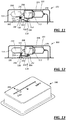
- a drug delivery device can include a reservoir, a cannula, a drive, a lock, a housing and a proximity sensor.
- the reservoir can include a bore having a first end and a second end, and a plunger assembly including a plunger moveable within the bore between the first and second ends.
- the cannula can have an operational state wherein the cannula is connected in fluid communication with the reservoir.
- the drive can be coupled to the plunger assembly to move the plunger between the first and second ends.
- the lock can be configured to selectively limit movement of the plunger between the first and second ends of the reservoir
- the reservoir, the drive, and the lock can be disposed at least partially within the housing.
- the proximity sensor can be operably coupled to move relative to the housing, and can have a first sensor state wherein the proximity sensor extends from the housing and a second sensor state wherein the proximity sensor is retracted toward the housing relative to the first sensor state.
- the lock can limit movement of the plunger assembly when the proximity sensor is in the first sensor state.
- a method of limiting the delivery of a drug from a drug delivery device after the drug delivery device is removed from a patient can be provided.
- the method can include (a) providing a drug delivery device, wherein the drug delivery device can include a reservoir, a cannula, a drive, a lock, a housing and a proximity sensor.
- the reservoir can include a bore having a first end and a second end, and a plunger assembly including a plunger moveable within the bore between the first and second ends.
- the cannula can have an operational state wherein the cannula is connected in fluid communication with the reservoir.
- the drive can be coupled to the plunger assembly for moving the plunger between the first and second ends.
- the lock can be configured to selectively limit movement of the plunger between the first and second ends of the reservoir.
- the reservoir, the drive, and the lock can be disposed at least partially within the housing.
- the proximity sensor can be operably coupled to move relative to the housing, and can have a first sensor state wherein the proximity sensor extends from the housing and a second sensor state wherein the proximity sensor is retracted toward the housing relative to the first sensor state.
- the lock can limit movement of the plunger assembly when the proximity sensor is in the first sensor state.
- the method can further include, (b) when the drug delivery device is removed from the patient, causing the proximity sensor to occupy the first sensor state after having occupied the second sensor state.
- the method can include, (c) transmitting information from the proximity sensor to the lock to indicate that the proximity sensor has moved to the first sensor state.
- the sensor can include (d) causing the lock to limit movement of the plunger assembly upon receiving information that the proximity sensor is in the first sensor state.
- a drug delivery device such as an injector can include a reservoir including a bore having a first end and a second end, and a plunger assembly including a plunger moveable within the bore between the first and second ends, and a cannula having an operational state wherein the cannula is connected in fluid communication with the reservoir.
- the injector also includes a spring coupled to the plunger assembly to move the plunger between the first and second ends, a lock selectively coupled to one of the plunger assembly and the spring to limit movement of the plunger between the first and second ends with the lock coupled to the one of the plunger assembly and the spring, a housing, the reservoir, spring, and lock disposed within the housing, and a proximity sensor coupled to the lock and moveable relative to the housing, the proximity sensor having a first sensor state wherein the proximity sensor extends fully from the housing and a second sensor state wherein the proximity sensor is retracted toward the housing, the lock coupled to the one of the plunger assembly and the spring with the proximity sensor in the first sensor state.
- a drug delivery device such as an injector can include a reservoir including a bore having a first end and a second end, and a plunger assembly including a plunger moveable within the bore between the first and second ends, and a cannula having an operational state wherein the cannula is connected in fluid communication with the reservoir.
- the injector also includes a gas source having an operational state wherein the gas source is in fluid communication with the plunger to move the plunger between the first and second ends, a lock comprising a vent selectively coupled to the gas source to limit movement of the plunger between the first and second ends, a housing, the reservoir, gas source, and lock disposed within the housing, and a proximity sensor coupled to the lock and moveable relative to the housing, the proximity sensor having a first sensor state wherein the proximity sensor extends fully from the housing and a second sensor state wherein the proximity sensor is retracted toward the housing, the vent coupled to the gas source with the proximity sensor in the first sensor state.
- a drug delivery device such as an injector can include a reservoir including a bore having a first end and a second end, and a plunger assembly including a plunger moveable within the bore between the first and second ends, and a cannula having an operational state wherein the cannula is connected in fluid communication with the reservoir.
- the injector also includes a spring coupled to the plunger assembly to move the plunger between the first and second ends, an indicator selectively mechanically coupled to the plunger assembly, a housing, the reservoir, spring, and indicator at least partially disposed within the housing, and a proximity sensor coupled to the indicator and moveable relative to the housing, the proximity sensor having a first sensor state wherein the proximity sensor extends fully from the housing and a second sensor state wherein the proximity sensor is retracted toward the housing, the indicator coupled to the plunger assembly with the proximity sensor in the second sensor state and the indicator decoupled from the plunger assembly with the proximity sensor in the first sensor state.
- a drug delivery device in the form of an injector, may include various systems for limiting the delivery of a medical fluid or drug product in case of movement of (e.g., removal of) the injector relative to a patient as determined by a proximity sensor.
- the drug delivery system may in the alternative or in addition include systems for indicating the amount of medical fluid or drug product delivered (or not delivered) in the case of movement of (e.g., removal of) the injector relative to the patient as determined by the proximity sensor.
- the injector may be, for example, an on-body injector or a hand-held autoinjector.
- the injector may be used with one of a variety of medical fluids or drug products.
- an injector comprises a reservoir including a bore having a first end and a second end, and a plunger assembly including a plunger moveable within the bore between the first and second ends.
- the injector further comprises a cannula having an operational state wherein the cannula is connected in fluid communication with the reservoir, and a spring coupled to the plunger assembly to move the plunger between the first and second ends.
- the injector also comprises a lock selectively coupled to one of the plunger assembly and the spring to limit movement of the plunger between the first and second ends with the lock coupled to the one of the plunger assembly and the spring, a housing, the reservoir, spring, and lock disposed within the housing, and a proximity sensor coupled to the lock and moveable relative to the housing, the proximity sensor having a first sensor state wherein the proximity sensor extends fully from the housing and a second sensor state wherein the proximity sensor is retracted toward the housing, the lock coupled to the one of the plunger assembly and the spring with the proximity sensor in the first sensor state.
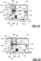
- the plunger assembly includes a plunger arm attached to the plunger, the lock has a wall that abuts the plunger arm to limit movement of the plunger when the lock is coupled to the plunger assembly, and the proximity sensor is coupled to the wall, where the wall abuts the plunger arm with the proximity sensor in the first sensor state and the wall is spaced from the plunger arm with the proximity sensor in the second sensor state.
- the plunger arm may have at least one shoulder formed thereon, and the wall abuts the at least one shoulder of the plunger arm to limit movement of the plunger when the lock is coupled to the plunger assembly.
- the injector further comprises a plate disposed at least partially within the housing and coupled to the housing to translate relative to the plunger arm, the plate having a first end that defines the wall of the lock and a second end that defines the proximity sensor.
- the injector further comprises a lever having a first end disposed within the housing and defining the wall of the lock, and a second end disposable outside the housing and defining the proximity sensor.
- the lock has a wall that abuts the spring to limit movement of the plunger when the lock is coupled to the spring, and the proximity sensor is attached to the wall, where the wall abuts the spring with the proximity sensor in the first sensor state and the wall is spaced from the spring with the proximity sensor in the second sensor state.
- the injector further comprises a plate disposed at least partially within the housing and coupled to the housing to translate relative to the spring, the plate having a first end that defines the wall of the lock and a second end that defines the proximity sensor.
- the injector further comprises a lever having a first end disposed within the housing and defining the wall of the lock, and a second end disposable outside the housing and defining the proximity sensor.
- the injector further comprises a spring coupled to the proximity sensor, the spring biasing the proximity sensor toward the first sensor state.
- the lock is reversibly coupled to the one of the plunger assembly and the spring.
- the lock is irreversibly coupled to the one of the plunger assembly and the spring.
- the proximity sensor has a third sensor state wherein the proximity sensor is retracted toward the housing, the lock being coupled to the one of the plunger assembly and the spring with the proximity sensor in the third sensor state, the lock being reversibly coupled to the one of the plunger assembly and the spring with the sensor occupying the third sensor state subsequent to occupying the second sensor state, and the lock being irreversibly coupled to the one of the plunger assembly and the spring with the sensor occupying the first sensor state subsequent to occupying one of the second and third sensor states.
- the lock prevents movement of the plunger between first and second ends with the lock coupled to the one of the plunger assembly and the spring.
- the lock limits movement of the plunger between first and second ends with the lock coupled to the one of the plunger assembly and the spring.
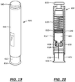
- the injector is a hand-held autoinjector, the injector comprising a needle shield that defines the proximity sensor.
- the injector is an on-body injector, the injector comprising a surface having adhesive applied thereto to attach the injector to a body of a patient.
- an injector comprises a reservoir including a bore having a first end and a second end, and a plunger assembly including a plunger moveable within the bore between the first and second ends, a cannula having an operational state wherein the cannula is connected in fluid communication with the reservoir, and a gas source having an operational state wherein the gas source is in fluid communication with the plunger to move the plunger between the first and second ends.
- the injector further comprises a lock comprising a vent selectively coupled to the gas source to limit movement of the plunger between the first and second ends, a housing, the reservoir, gas source, and lock disposed within the housing, and a proximity sensor coupled to the lock and moveable relative to the housing, the proximity sensor having a first sensor state wherein the proximity sensor extends fully from the housing and a second sensor state wherein the proximity sensor is retracted toward the housing, the vent coupled to the gas source with the proximity sensor in the first sensor state.
- a lock comprising a vent selectively coupled to the gas source to limit movement of the plunger between the first and second ends, a housing, the reservoir, gas source, and lock disposed within the housing, and a proximity sensor coupled to the lock and moveable relative to the housing, the proximity sensor having a first sensor state wherein the proximity sensor extends fully from the housing and a second sensor state wherein the proximity sensor is retracted toward the housing, the vent coupled to the gas source with the proximity sensor in the first sensor state.
- the gas source is a pressurized container of gas.
- the gas source is a container of a material capable of a phase change from liquid to gas or solid to gas.
- the vent comprises a seal.
- the vent comprises a piercable septum.
- an injector comprises a reservoir including a bore having a first end and a second end, and a plunger assembly including a plunger moveable within the bore between the first and second ends, a cannula having an operational state wherein the cannula is connected in fluid communication with the reservoir, and a spring coupled to the plunger assembly to move the plunger between the first and second ends.
- the injector further comprises an indicator selectively mechanically coupled to the plunger assembly, a housing, the reservoir, spring, and indicator at least partially disposed within the housing, and a proximity sensor coupled to the indicator and moveable relative to the housing, the proximity sensor having a first sensor state wherein the proximity sensor extends fully from the housing and a second sensor state wherein the proximity sensor is retracted toward the housing, the indicator coupled to the plunger assembly with the proximity sensor in the second sensor state and the indicator decoupled from the plunger assembly with the proximity sensor in the first sensor state.
- the plunger assembly comprises a plunger arm attached to the plunger, the indicator being mechanically coupled to the plunger arm through a gear train having at least one gear that is moveable into and out of engagement, and the proximity sensor is coupled to the at least one gear to move the at least one gear out of engagement and decouple the indicator from the plunger arm with the proximity sensor in the first sensor state.
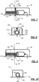
- a drug delivery device such as an injector 100 includes a reservoir 102, a plunger assembly 110, a cannula 114, and a drive 116.
- the reservoir 102 includes a bore 104 having a first end 106 and a second end 108.
- the plunger assembly 110 includes a plunger 112 moveable within the bore 104 of the reservoir 102 between the first and second ends 106, 108.
- the cannula 114 includes an operational state wherein the cannula 114 is connected in fluid communication with the reservoir 102.
- the drive 116 in the form of a spring, is coupled to the plunger assembly 110 to move the plunger 112 between the first and second ends 106, 108.
- the injector 100 is also provided with a lock 118 selectively coupled to one of the plunger assembly 110 and the drive 116 to limit movement of the plunger 112 between the first and second ends 106, 108 of the bore 104.
- the lock 118 may be coupled to the one of the plunger assembly 110 and the spring 116. See, e.g., Figs. 1-10 .
- Another embodiment of the lock 118 is illustrated in Figs. 11 and 12 .
- the injector 100 includes a proximity sensor 120 coupled to the lock 118 and moveable relative to a housing 122 in which the reservoir 102, spring 116, and lock 118 are disposed.
- the proximity sensor 120 has a first sensor state (or position) wherein the proximity sensor 120 extends (e.g., extends fully) from the housing 122 (see, e.g., Figs. 1 and 2 ) and a second sensor state (or position) wherein the proximity sensor 120 is retracted toward and into the housing 122 relative to the first sensor state (see, e.g., Fig. 3 ).
- the lock 118 is coupled to the one of the plunger assembly 110 and the spring 116 with the proximity sensor 120 in the first sensor state so as to limit or prevent movement of the plunger 112.
- the reservoir 102 may be in the form of a pre-filled syringe, in which case the cannula 114 may be in the form of a needle fixedly or securely attached to a hub 130 at the second end 108 of the reservoir 102. See, Fig. 1 .
- the reservoir 102 may be pre-filled, but the cannula 114 may be moveable relative to the hub 130 of the reservoir 102.
- the hub 130 can include a septum such that the cannula 114 can be moved in the direction of the hub 130 to pierce the septum in the operational state.
- an assembly may be disposed between the cannula 114 and the hub 130 to dispose the cannula 114 into fluid connection with the hub 130 in the operational state, which assembly may also insert the cannula 114 into the patient.
- a barrier may be disposed about the end of the cannula 114 that pierces the septum to preserve the sterility at the junction between the cannula 114 and the septum.
- the cannula 114 either may be fixedly or securely attached or may be moveable relative to the reservoir 102 (more particularly, the hub 130), but the reservoir 102 may not be pre-filled.
- the plunger assembly 110 may include a plunger arm 140 attached to the plunger 112.
- the lock 118 has a wall 142 that abuts the plunger arm 140 to limit movement of the plunger 112 when the lock 118 is coupled to the plunger assembly 110.
- the proximity sensor 120 is coupled to the wall 142 (as illustrated, the sensor 120 is integral, or one piece, with the wall 142), such that the wall 142 abuts the plunger arm 140 with the proximity sensor 120 in the first sensor state ( Figs. 1 and 2 ) and the wall 142 is spaced from the plunger arm 140 with the proximity sensor 120 in the second sensor state ( Fig. 3 ).
- the plunger arm 140 may have at least one shoulder 144 ( Fig. 1 ) formed thereon, and the wall 142 abuts the at least one shoulder 144 of the plunger arm 140 to limit and/or prevent movement of the plunger 112 when the lock 118 is coupled to the plunger assembly 110.
- the plunger arm 140 has a section of its length (i.e., a dimension of the plunger arm 140 extending in a direction along a longitudinal axis 148 of the plunger arm 140) that has at least one feature 150 that defines the at least one shoulder 144.
- the plunger arm 140 may include a shaft 152 to which is attached one or more features 150 that include protrusions 154 (e.g., teeth).
- the protrusions 154 can be formed integrally (as one piece) with the shaft 152. Spaces or notches 156 between adjacent protrusions 154 permit the wall 142 to be disposed between adjacent protrusions 154, with the protrusion 154 positioned furthest longitudinally from the plunger 112 defining the shoulder 144 along a surface of the protrusion 154 that extends perpendicularly to the axis 148.
- the lock 118 includes a wall 142 that fits in the spaces or notches 156 thereby coupling the lock 118 to the plunger assembly 110.
- the injector 100 includes a plate 158 disposed at least partially within the housing 122 and coupled to the housing 122 to translate relative to the plunger arm 140.
- the plate 158 may have a first end 160 that defines the wall 142 of the lock 118 and a second end 162 that defines the proximity sensor 120. See Figs. 2 and 3 .
- the wall 142 has been described as being part of the plate 158, which is depicted in Figs. 2 and 3 , for example, as a generally planar structure, this is merely an example.
- the wall 142 of the lock 118 could also be defined by part of a pin, a fork, or any other component not expressly depicted but capable of serving the intended purpose.
- the injector 100 may include a spring 166 coupled to the proximity sensor 120 (via the plate 158), the spring 166 biasing the proximity sensor 120 (again, via the plate 158) toward the first sensor state.
- the second end 160 may include a guide 172 about which the spring 166 is disposed, a first end 174 of the spring 166 abutting a shoulder 176 of the plate 158 and a second end 178 abutting an interior surface 180 of the housing 122. While a coil spring 166 is illustrated, any of a number of different biasing elements may be used, which biasing elements may bias the first end 162 of the plate 158 outwardly from the housing 122.
- the injector 100 may include guides attached to the housing 122 that prevent the plate 158 from other than translational movement along a line of motion 182.
- a guide may be disposed on either side of the plate (i.e., to the right or the left of the plate 158 as illustrated in Fig. 2 ) to prevent lateral movement relative to the line of motion 182.
- an aperture 184 Disposed between the first and second ends 160, 162 of the plate 158 is an aperture 184. While the aperture 184 appears to be closer to the second end 160 of the plate 158 than the first end 162, other arrangements are possible. Furthermore, while the aperture 184 appears to be fully surrounded by the plate 158, such that the entire circumference of the aperture 184 is defined by the plate 158, it is also possible that at least a section of the aperture 184 is not surrounded by the plate 158 and thus the plate 158 only partially defines the circumference of the aperture 184. Furthermore, while the circumference of the aperture 184 appears oblong or keyhole in shape in Fig. 2 , the aperture 184 is not limited to any particular shape.
- the proximity sensor 120 extends from the housing 122 as a consequence of the force applied to the plate 158 by the spring 166. See Fig. 2 .
- the plate 158 is positioned relative to the plunger assembly 110, and in particular the plunger arm 140, such that the plate 158 resides within one of the spaces or notches 156. Compare Figs. 1 and 2 .
- the proximity sensor 120 is moved into the housing 122 against the bias of the spring 166.
- the plate 158 is moved into a position where the aperture 184 is aligned with the plunger arm 140, such that the plate 158 no longer resides within one of the spaces or notches 156. See Fig. 3 .
- This permits movement of the plunger arm 140 and associated plunger 112 as a consequence of the force applied to the plunger arm 140 by the spring 116.
- the injector 100 may become detached or displaced from the patient's skin.
- the plate 158 would be permitted to move under bias of the spring 166 such that the aperture 184 is no longer aligned with the plunger arm 140, and instead the plate 158 becomes disposed within one of the spaces or notches 156.
- the spring 166 transmits information to the lock 118 in the form of a mechanical force indicative of the position of the plate 158 and proximity sensor 120.
- This force can cause engagement between the plate 158 and one of the protrusions 154 that would prevent further motion of the plunger arm 140 at the urging of the spring 116, and would limit the amount of medical fluid or drug product ejected from the reservoir 102. That is, according to certain embodiments, engagement between the plate 158 and a protrusion may prevent any further medical fluid or drug product from passing through and out of the cannula 114.
- the plunger arm 140 and associated plunger 112 may travel some distance after the plate 158 becomes disposed within a space or notch 156 but before the plate 158 engages a protrusion 154, such that a limited amount of medical fluid or drug product may pass out of the reservoir through the cannula 114 even after activation of the lock 118. It will be recognized that by limiting the amount of medical fluid or drug product ejected from the reservoir 102, while arresting the overall motion of the plunger 112, significant advantages may still be obtained.
- the lock 118 and proximity sensor 120 be defined by a translating plate, such as is illustrated in Figs. 1-3 .
- the embodiment illustrated in Figs. 4 and 5 includes a different structure that defines both a lock 118 and a proximity sensor 120. Because many of the structures of the embodiment of the injector illustrated in Figs. 4 and 5 are identical to those of the embodiment of Figs. 1-3 , like elements have like reference numerals.
- the structure of the embodiment illustrated in Figs. 4 and 5 that defines both the lock 118 and the proximity sensor 120 is a lever 190.
- the lever 190 has a first end 192 disposed within the housing 122 and defining the wall 142 of the lock 118, and a second end 194 disposable outside the housing 122 and defining the proximity sensor 120. Disposed between the first and second ends 192, 194 is a pivot 196 that may be attached to the housing 122.
- the injector 100 may include a spring 198 coupled to the proximity sensor 120, the spring 198 biasing the proximity sensor 120 (lever 190) toward the first sensor state with the sensor 120 extending from the housing 120.
- the spring 198 is a torsion spring that is disposed at the pivot 196 and that applies a force to the lever 190 to one or the other side of the lever 190 to bias the lever 190, and thus the sensor 120, toward the first sensor state (i.e., in a clockwise direction relative to the orientation of Fig. 5 ).
- a compression spring may be disposed between the first end 192 of the lever 190 and the housing 122 to urge the lever 190, and thus the sensor 120, toward the first sensor state.
- Some change in orientation of the elements of the injector 100 may be required to utilize the lever 190. Because the motion of the second end 194 of the lever 190 into the housing 122 causes the first end 192 to move counter-clockwise, the orientation of the plunger arm 140, and the spaces or notches 156 on the plunger arm 140, may be the reverse of that illustrated in the embodiment of Figs. 1-3 . The spaces or notches 156 may be positioned below the plunger arm 140, as depicted in Fig. 4 . In this fashion, movement of the lever 190 caused by the motion of the second end 194 upon application of the injector 100 to the patient's skin would cause the first end 192 to move away from the plunger arm 140 and out of its respective space or notch 156.
- the spring 198 upon removal of the injector 100 from the patient's skin, whether deliberate or not, the spring 198 would cause the first end 192 of the lever 190 to move toward the plunger arm 140 and into a respective space or notch 156 to lock the device.
- the spring 198 transmits information to the lock 118 in the form of a mechanical force indicative of the position of the lever 190 and thus the proximity sensor 120.
- the lever 190 can permit a magnification of the travel of the second end 194, which in turn can increase the sensitivity of the proximity sensor 120.
- the second end 194 moves a distance d relative to the surface of the housing 122 (for purposes of this discussion, this surface is also the patient contact surface).
- the first end 192 in turn moves a distance D relative to the same surface of the housing 122.
- These distances (d, D) are related to a length L of the lever 190, a length 1 of the lever 190 to the second end 194 and the offset H of the pivot 196 relative to the surface of the housing 122.
- the sensitivity of the embodiment utilizing a lever 190 may also be influenced by changes in the shape of the lever 190.
- the lever 190 illustrated in Figs. 4-6 is relatively straight.
- the lever 190 may be shaped with a bend between the two ends 192, 194 to change the relationship between the movement of the second end 194 to the first end 192.
- both the lock 118 and the sensor 120 may each be defined by a translating plate, similar to the plate 158, except that the first plate that defines the lock 118 may be disposed in a first region of the injector 100 and the second plate that defines the sensor 120 may be disposed in a second region of the injector 100 spatially removed from the first region.
- the second plate that defines the sensor 120 may be coupled to the first plate that the defines the lock 118 by a lever or other mechanical system disposed within the housing.
- a pivot for the lever coupling the sensor 120 to the lock 118 may be selected to provide greater sensitivity that may be possible if a single structure defined both lock 118 and sensor 120.
- a lever may permit the sensor 120 to be disposed closer to the cannula 114 while the lock 118 is disposed proximate to the plunger arm 140, because the lock 118 and the sensor 120 are not defined by a single structure.
- an intermediate structure or assembly may couple a sensor 120 moving in a first direction to a lock 118 moving in a second direction, which direction may be different from the first (i.e., the sensor 120 may travel along a first line of motion while the lock 118 moves along a second line of motion that is at right angles to the first line of motion).
- the lock 118 may be coupled to one of the plunger assembly 110 and the spring 116. As illustrated in Figs. 7-10 , the lock 118 may be coupled to the spring 116 instead of the plunger assembly 110.
- the plunger assembly 110 may or may not include a plunger arm 140. As illustrated in Figs. 7-10 , the plunger assembly 110 does not include a plunger arm 140, but the spring 116 acts directly against the plunger 112, the force applied by the spring 116 causing motion of the plunger 112. It will be recognized that the embodiments of the lock 118 described below would work equally as well if the spring 116 applied its force to an intermediate structure, such as a plunger arm 140, instead of directly to the plunger 112.
- the lock 118 has a wall 200 that abuts the spring 116 to limit movement of the plunger 112 when the lock 118 is coupled to the spring 116.
- the spring 116 may be a coil spring, and the wall 200 may be disposed between adjacent coils 202 of the spring 116 to limit the force applied to the plunger 112.
- the proximity sensor 120 is attached to the wall 200, and the wall 200 abuts the spring 116 with the proximity sensor 120 in the first sensor state and the wall 200 is spaced from the spring 116 with the proximity sensor 120 in the second sensor state.
- the injector may include a spring 204 coupled to the proximity sensor 120, the spring 204 biasing the proximity sensor 120 toward the first sensor state.
- the embodiment illustrated in Figs. 7 and 8 may include a plate 206 that defines the wall 200.
- the plate 206 may be disposed at least partially within the housing 122 and coupled to the housing 122 to translate relative to the spring 116.
- the plate 206 may have a first end 208 that defines the wall 200 of the lock 118 and a second end 210 that defines the proximity sensor 120.
- the plate 206 includes an aperture 212 that is sized such that the spring 116 may pass through the plate 206 when the sensor 120 is in the second sensor state, the consequence of which would be for the spring 116 to move freely without interference from the plate 206 and exert a force against the plunger 112.
- the discussion relative to the operation and configuration of the plate 158 relative to the plunger arm 140 applies with equal force relative to the operation and configuration of the plate 206 relative to the spring 116.
- the spring 204 transmits information to the plate 206 of the lock 118 in the form of a mechanical force indicative of the position of the proximity sensor 120.
- the injector may include a lever 220, as illustrated in Figs. 9 and 10 , in substitution for the plate 206.
- the lever 220 may have a first end 222 disposed within the housing 122 and defining the wall 200 of the lock 118.
- the lever 220 may also have a second end 224 disposable outside the housing 122 and defining the proximity sensor 120.
- This injector may also include a spring 228 coupled to the proximity sensor 120, the spring 228 biasing the proximity sensor 120 (lever 220) toward the first sensor state.
- the spring 228 may be a torsion spring.
- the discussion relative to the operation and configuration of the lever 190 relative to the plunger arm 140 applies with equal force relative to the operation and configuration of the lever 220 relative to the spring 116.
- the spring 228 transmits information to the wall 200 of the lock 118 in the form of a mechanical force indicative of the position of the lever 220 and proximity sensor 120.
- the discussion above relative to the lock 118 and the sensor 120 being defined by a single structure or by separate structures coupled by one or more intermediate structures or assemblies of structures applies with equal force regarding the embodiments illustrated in Figs. 7-10 as it did relative to the embodiments illustrated in Figs. 1-6 .
- the lock 118 may be reversibly coupled to the one of the plunger assembly 110 and the spring 116.
- the lock 118 may be unlocked, or decoupled, if the proximity sensor 120 determines that the injector 100 has been replaced against the patient's skin.
- the lock 118 may be irreversibly coupled to the one of the plunger assembly 110 and the spring 116. Such embodiments would prevent the injector 100 from operating even if the injector 100 was repositioned against the patient's skin.
- the decision to make the lock 118 reversible or irreversible may be selected by the patient or caregiver using the delivery device.
- Fig. 1 One example of an irreversible lock 118 is illustrated in Fig. 1 , wherein all but one of the features 150 extending up from the plunger arm 140 can include transverse teeth 151 extending into spaces or notches 156 between the features 150.
- all of the features 150 include a tooth 151 except for the feature 150 located in closest proximity to the plunger 112. So configured, before the injector 100 is ever operated, the lock 118 resides in the space or notch 156 disposed between the plunger 112 and the adjacent toothless feature 150.
- the proximity sensor 120 and lock 118 move into the injector 100 to allow the plunger assembly 110 to drive the plunger 112 and administer drug to the patient.
- the lock 118 would be positioned in a space or notch 156 between two features 150, one of which includes a tooth 151.
- the tooth 151 resides above the lock 118, or in a recess formed in the lock 118, for example, such that a bottom surface of the tooth 151 engages an upward facing surface of the lock 118, thereby preventing the lock 118 and proximity sensor 120 from moving back up into the injector 100.
- Fig. 1 illustrates the features 150 as having the teeth 151, this would only apply to those injectors 100 where the lock 118 is irreversible. For a reversible lock 118, the injector 100 would not include the teeth 151.
- the injector 100 may have a lock 118 that is reversibly coupled and irreversibly coupled to one of the plunger assembly 110 and the spring 116 according to the state of the proximity sensor 120.
- the proximity sensor 120 may have a third sensor state wherein the proximity sensor 120 is retracted toward the housing relative to the first sensor state but not as far as the second sensor state.
- the third sensor state can be considered an intermediate state between the first and second sensor states. With the proximity sensor 120 in the third sensor state, the lock 118 can be coupled to the one of the plunger assembly 110 and the spring 116 to limit or prevent further movement of the plunger 112.
- the lock 118 may be reversibly coupled to the one of the plunger assembly 110 and the spring 116 with the proximity sensor 120 in the third sensor state subsequent to occupying the second sensor state. And, the lock 118 can be irreversibly coupled to the one of the plunger assembly 110 and the spring 116 with the proximity sensor 120 in the first sensor state subsequent to occupying one of the second and third sensor states.
- a patient applies the device to his or her skin.
- the proximity sensor 120 is disposed wholly or partially in the housing 120.
- the lock 118 is disengaged or uncoupled from the plunger assembly 110 or the spring 116, and the device begins injecting the medical fluid or drug product into the patient.
- the delivery device may be disturbed, causing a separation of the device from the patient's skin, as determined by the proximity sensor 120.
- This disturbance may cause the cannula 114 to only shallowly penetrate the patient's skin, but may not separate the injector 100 from the patient's skin to such a degree that the cannula 114 is completely removed or the sterility of the access site is compromised.
- the delivery of the medical fluid or drug product may be interrupted by the coupling of the lock 118 with the plunger assembly 110 or the spring 116 to prevent medical fluid or drug product leakage that may occur because of shallow cannula 114 penetration.
- this coupling is reversible so that an application of force that moves the cannula 114 back to its proper depth, as determined by the proximity sensor 120, will cause the lock 118 to decouple from the plunger assembly 110 or spring 116, thereby re-starting administration of the medical fluid or drug product.
- the medical fluid or drug product remaining in the reservoir 102 can be successfully delivered and would not end up being treated as waste. Consequently, reversible coupling of the lock 118 to the plunger assembly 110 or the spring 116 would provide an opportunity to save a dose in the event of a minor disturbance or use error. Additionally, this may provide a higher success rate on challenging anatomies by allowing applied pressure to fix or correct an "error" state and permit delivery to resume.
- the delivery device becomes disturbed to such a degree that the cannula 114 is completely removed from the patient (for example, the device falls completely off the patient) before the full dose has been administered, then it may be undesirable to permit the patient or caregiver to reapply the injector 100 to the patient. Consequently, to reduce the likelihood that the patient or caregiver would attempt to reapply the injector 100, the lock 118 may irreversibly couple to the plunger assembly 110 or spring 116 to prevent the injector 100 from any further drug delivery.
- the 3 mm depth may be referred to as a delivery continuation threshold, and may represent the point, degree or level under which continued delivery presents an unacceptable risk of leakage or improper administration.
- a delivery continuation threshold may represent the point, degree or level under which continued delivery presents an unacceptable risk of leakage or improper administration.
- the injector 100 may permit continued injection of the medical fluid or drug product.
- the injector 100 may reversibly limit injection of the medical fluid or drug product by reversibly coupling the lock 118 to one of the plunger assembly 110 and the spring 116. If the sensor 120 then moves back to a state corresponding to a cannula depth of 3 mm (e.g., the sensor 120 extends 3 mm from the housing 122) or more, then the injection may resume.
- a depth of 0 mm may be referred to as a device removal threshold, and may represent the point, degree or level at which the device has likely been compromised, removed or the cannula 114 disturbed such that further delivery/reapplication is undesirable or unsafe.
- a similar outcome may result where the cannula depth is not 0 mm, but some non-zero value (e.g., 1 mm).
- a non-zero value may be selected because even if the cannula 114 does not come completely out of the patient's skin, this may still be considered to present an unacceptable risk.
- a non-zero value may be selected so that it is not a requirement that the sensor 120 determine complete separation to fail-safe in case of a false negative for complete separation (e.g., partial interference between the housing 122 and the sensor 120).
- any particular embodiment may be influenced by, for example, the distance to which the proximity sensor 120 extends from the housing 120, the length of the cannula 114, the desired depth of the insertion of the cannula 114 into the patient, and the relationship between the depth of cannula insertion to the degree of leakage from the access site.
- the lock 118 may limit movement of the plunger 112 between first and second ends 106, 108 so as to completely prevent movement of the plunger 112 between the first and second ends 106, 108 upon the lock 118 being coupled to the one of the plunger assembly 110 and the spring 116.
- the lock 118 may only limit movement of the plunger 112 between first and second ends 106, 108 without completely preventing movement of the plunger 112 between the first and second ends 106, 108 upon the lock 118 being coupled to the one of the plunger assembly 110 and the spring 116.
- the plunger 112 may continue its movement over a limited length of travel after activating the lock 118.
- the specific distance that the plunger 112 may travel may be known and predetermined, as a consequence of the structure and operation of the lock 118, or the distance may be approximated based on the structure and operation of the lock 118 or the tolerances in the manufacture of the injector 100.
- any limited length of travel of the plunger 112 that is allowed after engagement or coupling of the lock 118 can occur, for example, because of the geometry of the wall 142 that forms the lock 118 and the spaces or notches 156 on the plunger arm 140. That is, in some embodiments, the spaces or notches 156 may have a dimension that is greater than a thickness or width of the wall 142. As such, it is foreseeable that in some embodiments, the plunger 112 can continue to move to the extent that the spaces or notches 156 are wider, even after the lock 118 has been engaged or coupled.
- Those embodiments described above wherein the lock 118 engages or couples to the plunger assembly 110, and in particular the plunger arm 140, may be used with embodiments of an injector 100 wherein the drive 116 is not in the form of a spring.
- any device that acts on the plunger arm 140 may be used as a drive 116 in the circumstance wherein the lock 118 engages or couples to the plunger assembly 110 to limit the injection of medical fluid or drug product from the injector 100.
- the drive 116 is not in the form of a spring, other considerations may be required when the injection is limited by interaction between the lock 118 and the drive 116.
- the injector includes a reservoir 102 including a bore 104 having a first end 106 and a second end 108, and a plunger assembly 110 including a plunger 112 moveable within the bore 104 between the first and second ends 106, 108.
- the injector 100 also includes a cannula 114 having an operational state wherein the cannula 114 is connected in fluid communication with the reservoir 102.
- Embodiments of the injector 100 illustrated in Figs. 11 and 12 include a drive 116 in the form of a gas source 250 having an operational state wherein the gas source is in fluid communication with the plunger 112 to move the plunger 112 between the first and second ends 106, 108.
- the gas source 250 may be a container of pressurized gas.
- the gas source 250 may be a container of a material capable of a phase change from liquid to gas or solid to gas. When activated, the gas source 250 applies positive pressure on the plunger 112 of the plunger assembly 110.
- the gas source 250 can include a frangible seal (similar to that on a convention CO 2 cartridge) that is punctured by a movable needle, for example, upon activation of the injector 100.
- the movable needle may be operably connected to the proximity sensor 120 such that movement of the proximity sensor 120 automatically moves the needle to puncture the frangible seal and activate the gas source 250.
- the injector 100 may include a separate button operably connected to the movable needle such that a user of the injector 100 must depress the button to move the needle and break the frangible seal on the gas source 250.
- the injector 100 can include a mechanical or electro-mechanical valve that opens and activates the gas source 250 upon activation of the injector 100, or some other structure capable of achieving the intended objective.
- the injector 100 includes a lock 118 comprising a vent 252 selectively coupled to the gas source 250 to limit or prevent movement of the plunger 112 between the first and second ends 106, 108.
- a lock 118 comprising a vent 252 selectively coupled to the gas source 250 to limit or prevent movement of the plunger 112 between the first and second ends 106, 108.
- the vent 252 could be provided by a number of different mechanisms, and may be dependent upon the manner in which the positive pressure is delivered to the plunger 112.
- the vent 252 could be defined by a rupturable wall or a moveable seal, which could provide an irreversible or a reversible lock.
- the vent 252 may be in the form of a duck-bill valve.
- the injector 100 could be considered as having an "irreversible" lock.
- the vent 252 limits or prevents the positive gas pressure from being applied against the plunger assembly 110.
- the open "vent” causes the lock to operate irreversibly because there is only a single pressure source (i.e., the gas source 250), and once its seal is broken, its contents will be expelled until it is empty, especially if a seal of the vent 252 is also broken. Therefore, if the injector 100 is removed from the patient prematurely, the gas source 250 continues to expel gas which is then exhausted out of the vent 252. Any subsequent attempt to re-administer will fail if the gas source 250 is spent.
- the vent 252 may include a seal 254, such as a piercable septum or a duck-bill valve, and a vent cannula 256.
- the vent cannula 256 pierces the seal 254 to provide an exhaust pathway out of the vent 252.
- the reservoir 102, gas source 250, and lock 118 may be disposed within the housing 122, while the proximity sensor 120 may be disposed in whole or in part outside of the housing 122.
- the proximity sensor 120 is coupled to the lock 118 and moveable relative to the housing 122.
- the proximity sensor 120 has a first sensor state wherein the proximity sensor 120 extends (e.g., extends fully) from the housing 122 and a second sensor state wherein the proximity sensor 120 is retracted toward and into the housing 122 relative to the first sensor state.
- the vent 252 is coupled to the gas source 250 with the proximity sensor 120 in the first sensor state.
- the injector 100 illustrated in Figs. 11 and 12 includes a chamber 258 that connects the gas source 250 with the reservoir 102.
- the vent 252 is disposed in a wall of the chamber 258.
- the vent cannula 256 which may be in the form of a blunt, open-ended needle, is attached to a first end 260 of a vent lever 262.
- the second end 264 of the vent lever 262 is coupled to the proximity sensor 120, which may be in the form of cup-shaped button 266 that extends through an aperture 268 in a wall of the housing 122. Movement of the button 266 is transmitted by the vent lever 262 to the vent cannula 256.
- the proximity sensor 120 and in particular the button 266, is biased outwardly from the housing 122 by a spring 274.
- the spring 274 may be disposed between a support 276 and the second end 264 of the vent lever 262, the button 266 being disposed opposite the support 276 relative to the end 264 of the vent lever 262.
- the vent cannula 256 engages the seal 254 to exhaust the chamber 258. Because the gas source 250 has not yet been activated, there is no effect on the movement of the plunger 112. However, once the proximity sensor 120 retracts into the housing 122, the vent cannula 256 is moved so that the vent cannula 256 no longer interrupts the seal 254 and a positive pressure may be generated in the chamber 258 by the gas source 250.
- the spring 274 biases the vent lever 262 such that the vent cannula 256 is moved into engagement with the seal 254, and the positive pressure in the chamber 258 is exhausted through the vent cannula 256. This decreases the pressure in the chamber 258, causing the movement of the plunger 112 to be limited, or even stopped.
- the spring 274 transmits information to the lock 118, and specifically the vent lever 262 and vent cannula 256, in the form of a mechanical force indicative of the position of the vent lever 262 and the proximity sensor 120.
- Figs. 11 and 12 The embodiment provided in Figs. 11 and 12 is intended to be an example only. Other structures may be substituted for the seal 254, vent cannula 256, and vent lever 262. While a chamber 258 has been provided in communication with the reservoir 102 and the gas source 250, the chamber 258 may not be present in other embodiments. Additionally, in some embodiments, the cannula 114 may be an open ended needle that allows flow, as depicted in Figs. 11 and 12 , or it could just be anything that when wedged into the seal 254 prevents sealing. As such, the cannula 114 could include a thin solid rod to create a flow path around itself where the seal is poor, or a square profile might encourage even more flow.
- An open ended needle as depicted might be useful for puncturing a septum, for example, since a septum could be designed to reseal around the perimeter of the needle.
- a duck-billed valve configuration may seal well when un-interrupted against pressure in one direction.
- the reservoir 102 may be visible through the wall of the housing 122. According to such embodiments, if the administration of the medical fluid or drug product is interrupted as a consequence of the operation of the lock 118, the patient or caregiver may be able to visually determine the amount of the full dose remaining in the reservoir 102. In other embodiments, the reservoir 102 may be completely enclosed within the housing 122 without provision for a window.
- a third group of embodiments of the injector is illustrated in Figs. 13-15 .
- This group of embodiments may be used in conjunction with any of the embodiments of the injector 100 described herein.
- These embodiments may be used with an injector with a reservoir 102 including a bore 104 having a first end 106 and a second end 108, and a plunger assembly 110 including a plunger 112 moveable within the bore 104 between the first and second ends 106, 108.
- a cannula 114 may also be included, having an operational state wherein the cannula 114 is connected in fluid communication with the reservoir 102.
- the injector 100 further includes a spring 116 coupled to the plunger assembly 110 to move the plunger 112 between the first and second ends 106, 108. All of these structures are illustrated in Figs. 1-3 , for example, and are also applicable to the embodiment described relative to Figs. 13-15 .
- the embodiment illustrated in Figs. 13-15 includes an indicator 290 mechanically coupled to the plunger assembly 110.
- the reservoir 102, plunger arm 140, and indicator 290 are at least partially disposed within a housing 122.
- a proximity sensor 120 is coupled to the indicator 290 and moveable relative to the housing 122, the proximity sensor 120 having a first sensor state wherein the proximity sensor 120 extends (e.g., extends fully) from the housing 122 and a second sensor state wherein the proximity sensor 120 is retracted toward the housing 122 relative to the first sensor state.
- the sensor 120 resembles the pivoting sensor 120 of Figs. 4-6 and 9-10 , and as such, it should be appreciated that the indicator 290 could be implemented into the embodiments of Figs. 4-6 and 9-10 or any other embodiments disclosed hereinabove. That is, the indicator 290 can be combined with other injectors with locks, as disclosed.
- the indicator 290 is coupled to the plunger assembly 110 with the proximity sensor 120 in the second sensor state and the indicator 290 is decoupled from the plunger assembly 110 with the proximity sensor 120 in the first sensor state.
- the indicator 290 mirrors the internal motion of the plunger 112 externally to the housing 122 to permit visualization. Once the proximity sensor 120 detects that the injector 100 has become detached from the patient, the indicator 290 would be decoupled from the plunger 112, such that the indicator 290 would reflect the portion of the dose remaining in the reservoir 102. According to certain embodiments, the indicator 290 may be reversibly coupled to the plunger assembly 110 so that if the injector 100 permits the injection to resume after the injector 100 is repositioned or otherwise adjusted, the indictor 290 would continue to mirror the motion of the plunger assembly 110 when the injection is resumed.
- the indicator 290 may be irreversibly decoupled from the plunger assembly 110 so that the condition of the injector 100 when an error in administration occurred would be preserved. Preserving the condition of the injector 100 may be useful in assisting the patient or caregiver in their determination for future action based on the amount administered through the intended method of administration (i.e., prior to the occurrence) and the patient's overall disease/therapy conditions.
- the plunger assembly 110 may include a plunger arm 140 attached to the plunger 112, as illustrated in Fig. 14 .
- the indicator 290 may be mechanically coupled to the plunger arm 140 through a gear train 292 having at least one gear 294 that is moveable into and out of engagement.
- the proximity sensor 120 may be coupled to the at least one gear 294 to move the at least one gear 294 out of engagement and decouple the indicator 290 from the plunger arm 140 with the proximity sensor 120 in the first sensor state.
- the gear train 292 includes the moveable pinion gear 294, as well as two racks 296, 298 formed on facing surfaces 300, 302 of the plunger arm 140 and the indicator 290.
- the gear 294 engages the racks 296, 298 simultaneously, as shown in Fig. 15 , the gear 294 transmits motion of the plunger arm 140 to the indicator 290.
- the gear 294 is disengaged from rack 296, as shown in Fig. 14 , the indicator 290 is decoupled from any motion of the plunger arm 140.
- the pinion gear 294 is biased toward engagement with the racks 296, 298 by a spring 304.
- a linkage 306 passes through the gear 294 at a first end 308, and is attached to a further linkage 310 at a second end 312.
- the linkage 310 may be a flexible linkage (as illustrated), in the form of a string or cord. In other embodiments, the linkage 310 may include a rigid mechanical linkage including additional levers, gears, couplings, etc.
- the depicted flexible linkage 310 may pass about a drum, wheel or pulley 314 and be connected to the proximity sensor 120.
- the proximity sensor 120 may be defined by a lever 316 having a first end 318 attached to the housing 112 at a pivot 320 and a second 322 that is attached to the linkage 310.
- the lever 316 may be biased to move clockwise about the pivot 320, as illustrated in Figs. 14 and 15 , by a further spring 324.
- the injector 100 of any of the foregoing embodiments may be an on-body injector, the injector 100 comprising a surface having adhesive applied thereto to attach the injector 100 to a body of a patient.
- Figs. 16-18 illustrates an on-body injector 400 that may incorporate any of the embodiments illustrated in Figs. 1-15 .
- the injector 400 may be a wearable, disposable system.
- the injector 400 may include a disposable housing 402 that may be attached to a patient or wearer with adhesive, for example.
- the disposable housing 402 may be made of a plastic material. As seen in Fig. 17 , the housing 402 may be defined by two sections, a plate 404 that is applied against the wearer's skin, and a dome 406 that is attached to the plate 404, preferably by a seal at an interface between a peripheral edge 408 of the plate 404 and a peripheral edge 410 of the dome 406.
- the housing 402 has an interior surface 412 defining an interior space 414, and an exterior surface 416.
- the plate 404 has an interior surface 418 and an exterior surface 420
- the dome 406 has an interior surface 422 and an exterior surface 424.
- the interior surface 412 of the housing 402 is defined by the interior surfaces 418, 422 of the plate 404 and the dome 406, while the exterior surface 416 of the housing 402 is defined by the exterior surfaces 420, 424 of the plate 404 and dome 406.
- the housing 402 may be attached to the skin of the wearer.
- an adhesive may be used.
- the adhesive may be adapted to releasably secure the housing to skin during a single application.
- the adhesive is disposed in a layer 426 on a portion 428 of the exterior surface 416 of the housing 402, and in particular on the exterior surface 420 of the plate 404.
- the adhesive is covered with a removable, disposable sheet 430 prior to application of the housing 402 to the skin of the wearer.
- a reservoir 440, a drive 442, a cannula (or structure, see below) 444, and an inserter 446 are disposed in the housing 402.
- the reservoir 440 may be defined at least in part by a combination of a rigid-walled cylinder or bore 450 having a port 452 at a first end 454 and a plunger 456 fitted to move along a longitudinal axis 458 of the cylinder 450 between a second end 460 and the first end 454 to force medical fluid or drug product out of the reservoir 440 through the port 452 ( Fig. 17 ).
- the movement of the plunger 456 may be caused by the operation of the drive 442.
- a valve 451 can be disposed at the exit of the port 452 between the reservoir 440 and a delivery line 453 that is fluidly coupled to the cannula 444.
- the drive 442 may include a plunger arm and a spring.
- the plunger arm may be in contact at least at a first end of the plunger 456 to urge the plunger 456 along the cylinder 450, and the spring may be coupled to the plunger arm to cause the plunger arm/plunger 456 to move along the longitudinal axis 458.
- the combination of the plunger arm and spring may also be referred to as one example of a drive or an actuator.
- Other mechanisms such as pressurized gases, materials undergoing phase changes and the like, may be used as the drive 442 to apply a force to the plunger 456 to move the plunger 456 along the cylinder 450.
- the drive 442 may be constructed according to the embodiments disclosed above relative to Figs. 1-12 , or any other embodiment capable of serving the intended purpose.
- a non-rigid collapsible pouch may be substituted for the rigid-walled cylinder 450 and the plunger 456 illustrated in Fig. 17 .
- a spring-based mechanical system may be used to compress and pressurize the reservoir 450.
- a non-mechanical system may be used to move the plunger 456 or compress the non-rigid collapsible reservoir.
- a gas-generating system may be used, including a two-component system wherein the components are kept apart until the gas is to be generated, in which case they are combined.
- a swellable gel may be used, wherein the introduction of water from a source internal to the device causes the gel to increase in dimension to move the plunger or compress the reservoir.
- a propellant reservoir may be opened and the propellant discharged to move the plunger 456 or compress the reservoir.
- Embodiments of the present disclosure could be used to prevent motion of the structures used to move the plunger 456 or compress the reservoir, thereby limiting such motion if the injector 400 were to separate from the patient during delivery.
- the reservoir 440 may be a pre-filled container, such as a pre-filled cartridge or a pre-filled syringe.
- the injector 400 may include a fill port 480 in fluid communication with the reservoir 440, the fill port 480 adapted to receive a luer tip of a syringe, although a rubber septum may be used instead, for example.
- a healthcare provider may inject the medical fluid or drug product from the syringe through the fill port 480 into the reservoir 440, and the syringe may be provided as a pre-filled syringe (filled with any of the materials mentioned above) to the healthcare provider with the delivery injector 400 as a kit.
- the cannula (or structure) 444 may have a retracted state wherein a pointed end 490 (or, the entire cannula 444) may be withdrawn inside the housing 402 and a deployed state wherein the pointed end 490 projects from the housing 402, the inserter 446 moving the cannula (or structure) 444 from the retracted state to the deployed state.
- the injector 400 includes a proximity sensor 120 similar to any one of the proximity sensors 1210 described above and which may extend from the housing 402 (specifically, the plate 404) in a similar fashion to the cannula 444, moving between extended and retracted states.
- the cannula 444 may be hollow, and may be used to administer the medical fluid or drug product directly to the patient.
- the structure 444 may be used in conjunction with a cannula 492 fitted about the structure 444, the structure 444 being used to insert the cannula 492 into the patient through the injection site, and the medical fluid or drug product passing through the catheter 492 into the patient during administration.
- the injector 400 may, according to certain exemplary embodiments, use a needle to automatically insert a soft cannula into the subcutaneous tissue with the needle being withdrawn prior to passage of medical fluid or drug product through the soft cannula.
- the housing 402 may have an aperture or opening 494 to permit the cannula (or structure) 444 (and optionally cannula 492) to pass therethrough.
- the aperture 494 may be unobstructed, such that there is no impediment or obstacle to the movement of the cannula 444 (and catheter 492) through the opening 494.
- a septum may be disposed in or over the aperture 494.
- the septum which may be made of a rubber, may be disposed between the cannula 444 (and the space 414) and the patient's skin with the needle 444 in the retracted state. In the deployed state, at least a portion of the needle 444 (i.e., the pointed end 490) will extend from the space 414 through the septum. As such, the septum is always present as a barrier between the interior space 414 and the external environment.
- the injector 400 includes a controller 500.
- the controller may include at least one processor and memory, the processor programmed to carry out the actions that the controller is adapted to perform, and the memory, including one or more tangible non-transitory readable memories, having executable instructions stored thereon, which instructions when executed by the at least one processor may cause the at least one processor to carry out the actions that the controller is adapted to perform.
- the controller may include circuitry that carries out the actions that the controller is adapted to perform.
- the controller 500 may be adapted to carry out any one of the methods described above relative to the drug delivery system.
- the lock and proximity sensor may be defined by a single structure, such as a plate or lever, or an assembly of structures, which collectively provide the function.
- the lock may be a structure defined separately from the proximity sensor.
- the movement of the proximity sensor may be detected through the use of a switch, such as a mechanical switch or optical switch, which switch may be coupled to the controller 500 and may provide information in the form of a signal (or signals, or an absence of signal (low vs. high)) to the controller 500 when the proximity sensor moves or changes positions or states.
- the lock can be the valve 451 connected to the controller 500, as depicted in Figs.
- the proximity sensor can include an electrical sensor (e.g., a Hall effect sensor) or an electromechanical sensor (e.g., a linear variable differential transformer (LVDT)), for example, mounted within the housing for detecting the position of the movable cannula 444 or other movable proximity sensor mounted to the housing.
- the controller 500 may thus be operatively coupled to the valve 451, and may be capable of transmitting information to the valve 451 in the form of a signal for changing the state of the valve 451 between positions or states in response to the signal received from the switch or other device coupled to the cannula 444 or other proximity sensor.
- the controller 500 may be coupled to an actuator, such as a linear actuator, that is capable of moving the valve 451 between opened and closed positions or states.
- the proximity sensor may have not only first and second states, but also one or more third states (e.g., intermediate states), where the lock (e.g., valve 451) may transition from occupying a reversible condition to an irreversible condition.
- This functionality could be therefore achieved through the use of the controller 500 in operable communication with the proximity sensor and lock (e.g., valve 451).
- the sensitivity or threshold for converting the lock condition from reversible to irreversible could be specifically managed by way of the logic or software stored on a memory of the controller 500 based on the specifc patient, the specific medical fluid or drug product being administered, or generally any other parameter.
- Figs. 21 and 22 depict an alternative version of the injector 400, wherein the lock includes a movable plate 461 similar to the proximity sensor 120 described with respect to Figs. 1-3 , for example.
- the plate 461 is spring biased into the position illustrated in Fig. 21 such that similar to prior embodiments, upon application of the injector 400 to a patient's skin, the plate 461 retracts into the housing 402 and into the position depicted in Fig. 22 .
- the plate 461 also includes an aperture 465 through which the fluid line 453 of the injector 400 passes.
- Figs. 21 and 22 depict an alternative version of the injector 400, wherein the lock includes a movable plate 461 similar to the proximity sensor 120 described with respect to Figs. 1-3 , for example.
- the plate 461 is spring biased into the position illustrated in Fig. 21 such that similar to prior embodiments, upon application of the injector 400 to a patient's skin, the plate 461 retracts into the housing 402 and into the position depicte
- the fluid line 453 is a flexible line. And, in Fig. 21 , an interior edge 463 of the aperture 465 in the plate 461 bears down against an upper sidewall of the fluid line 453 such that the plate 461 pinches the fluid line closed. In this manner, the interior edge 463 of the aperture 465 in the plate 461 limits or prevents fluid in the reservoir 440 from travelling past the pinched portion of the fluid line 453.
- the plate 461 thus serves as the lock.
- the injector 400 is applied to a patient's skin, the plate 461 retracts sufficiently far into the housing that the interior edge 463 of the aperture 465 moves out of engagement with the fluid line, as shown in Fig. 22 , such that medical fluid or drug product stored in the reservoir 440 can freely pass through the fluid line 453 under the operation of the drive 442.
- the injector of any of the foregoing embodiments may be a hand-held autoinjector 600, the injector comprising a needle shield that defines the proximity sensor. See Figs. 19 and 20 .
- the autoinjector 600 may include a housing 610 in which may be disposed assemblies or structures that insert or enable insertion of a cannula into the patient, and that inject a medical fluid or drug product from the reservoir through the cannula into the patient.
- the same assemblies or structures that insert the cannula into the patient may also allow flow of the medical fluid or drug product from the reservoir through the cannula into the patient.
- the autoinjector 600 may also include assemblies or structures that connect the cannula to the reservoir, that withdraw the cannula into the housing 610, or that deploy other structures that will prevent contact with the cannula once the cannula has been removed from the patient.
- the specific embodiment of the autoinjector 600 discussed below is provided by way of example and not of limitation.
- the autoinjector 600 may or may not include assemblies or structures that direct or force insertion of the cannula (e.g., needle) into the patient.
- the cannula may be substantially fixed relative to the housing of the autoinjector 600 such that insertion of the cannula into the patient simply results from moving the cannula into contact with the patient.
- the drug delivery system 600 includes a reservoir 612 and a cannula 614 having a first end 616 that may be connected or connectable in fluid communication to the reservoir 612 and a second end 618 that may be inserted into a patient.
- the cannula 614 may be, for example, a rigid needle having a beveled edge that may be sized such that the second end 618 of the needle 614 is received under the skin so as to deliver a subcutaneous injection of the medical fluid or drug product within the reservoir 612.
- the first end 616 of the needle 614 may be disposed through a wall 620 of the reservoir 612, and thus be connected in fluid communication with the reservoir 612.
- the first end 616 of the needle 614 may be disposed only partially through the wall 620 (which wall 620 may be a resealable septum or stopper, for example) such that the first end 616 of the needle 614 may not be connected in fluid communication with the reservoir 612 until the second end 618 of the needle 614 is inserted into the patient.
- the wall 620 of this embodiment is a lock, as used herein, and as will be described.
- the first end 616 of the needle 614 may again become disconnected from fluid communication with the reservoir 612.
- first end 616 of the needle 614 may be described as connectable in fluid communication with the reservoir 612, although it will be recognized that there are other mechanisms by which the first end 616 of the needle 614 may be connectable, but not connected, in fluid communication with the reservoir 612.
- the drug delivery device 600 includes a shield 622 that may be deployed at least after the injection has been completed to limit access to the second end 618 of the needle 614.
- the shield 622 may have a biasing element (such as a spring) that extends the shield 622 from the housing 610 such that a distal end 626 of the shield 622 extends beyond the second end 618 of the needle 614 except when the shield 622 is disposed against the skin and the injection of the needle 614 is actuated.
- the injection of the needle 614 may be actuated according to certain embodiments of the autoinjector 600 by disposing the distal end 626 of the shield 622 on or against the skin of the patient.
- the shield 622 may define the proximity sensor 120.
- the drug delivery device 600 includes at least one drive 630 that may be used to insert the second end 618 of the needle 614 into the skin of the patient, and to inject the medical fluid or drug product from the reservoir 612 through the needle 614 into the patient.
- the drive 630 may include one or more springs, according to certain embodiments.
- the drive 630 may include a source of pressurized gas or a source of a material that undergoes a phase change, such that the escaping gas or phase changing material that provides a motive force that may be applied to the reservoir 612 to eject the medical fluid or drug product therefrom.
- the drive 630 may include an electromechanical system, such as a motor.
- the drive 630 may cooperate with a wall 632 of the reservoir 622 to move that wall 632 toward the patient's skin.
- the wall 632 may be a stopper that is received within a bore 634, and which may move along the bore 634 from a first end to a second end to inject the medical fluid or drug product from the reservoir 612.
- the drive 630 may also cooperate with the wall 632 and/or the bore 634 to move the reservoir 612 relative to the housing 610 so as to move the second end 618 of the needle 614 relative to the housing 610 and into the patient. According to those embodiments wherein the drive 630 cooperates with the stopper 632, this may occur before the first end 616 of the needle 614 is in fluid communication with the reservoir 612.
- the drive may include one component (e.g., first spring) that cooperates with the bore 634 to move the reservoir 612 and needle 614 relative to the housing 610, and a second component (e.g., second spring) that cooperates with the stopper 632 to move the stopper 632 relative to the bore 634.
- first spring e.g., first spring
- second spring e.g., second spring
- the drive 630 is associated with an actuator 640.
- the actuator 640 activates the drive to cause the drive 630 to insert the needle 614 and inject the medical fluid or drug product from the reservoir 612 through the needle 614 into the patient.
- the actuator 640 may, according to certain embodiments, be the shield 622. According to other embodiments, the actuator 640 may be a button that may be depressed by the user once the autoinjector 600 is disposed on or against the patient's skin. While the embodiment illustrated in Figs. 19 and 20 has the actuator 640 disposed at one end of the device, the actuator 640 could be disposed on the side of the device.
- the autoinjector 600 may include at least one processor and memory.
- the controller may also include or be coupled to a power supply, e.g. a battery.
- the processor may be programmed to carry out the actions that the controller is adapted to perform and the memory may include one or more tangible non-transitory readable memories having executable instructions stored thereon, which instructions when executed by the at least one processor may cause the at least one processor to carry out the actions that the controller is adapted to perform.
- the controller may include other circuitry that carries out the actions that the controller is adapted to perform.
- the wall 620 Before the first end 616 penetrates the wall 620, the wall 620 seals the reservoir 612 from communicating with the needle 614 and thereby limits the movement of the wall 632 or stopper in the bore 634. In this way, the wall 620 is a lock, as used herein. But as mentioned above, as the second end 618 of the needle 614 of the autoinjector 600 of Figs. 19 and 20 is inserted into a patient, the first end 616 of the needle 614 penetrates the wall 620 to become in fluid communication with the reservoir 612.
- the first end 616 of the needle 614 may again become disconnected from fluid communication with the reservoir 612 by, for example, being drawn back through the wall 620 at least such that the first end 616 of the needle 614 no longer resides within the reservoir 612, but rather resides inside of the wall 620 or, said another away, resides at a point between opposing surfaces of the wall 620.
- the wall 620 can automatically seal the opening through which the first end 616 of the needle 614 previously passed into the reservoir, and thereby locks the fluid delivery mechanism.
- the autoinjector 600 includes a needle assembly 700 for disconnecting the needle 614 from fluid communication with the reservoir 612 when the needle 614 is removed from the patient.
- the needle assembly 700 includes a retainer 702 and a biasing member such as spring 704.
- the retainer 702 is fixed to the needle 614 and slidably disposed in the housing 610 adjacent to the shield 622.
- the spring 704 can be a coil spring and is disposed between the wall 620 of the reservoir 612 and the retainer 702.
- a top surface 706 of the retainer 702 defines an annular recess 708 into which a first end 710 of the spring 704 is seated.
- a second end 712 of the spring 704 is seated against the wall 620 (or a component surrounding the wall 620). So configured, the spring 704 biases the needle assembly 700 away from the reservoir 612 and the wall 620 (i.e., downward relative to the orientation of the autoinjector 600 depicted in Fig. 23 ).
- a bottom surface 714 of the retainer 702 bears against the patient's skin and therefore serves as the proximity sensor in this embodiment.
- the needle assembly 700 moves into the housing 610 against the force of the spring 704 such that the first end 616 of the needle 614 fully penetrates the wall 620 and becomes in fluid communication with the reservoir 612. This allows medicament in the reservoir 612 to pass into the first end 616 of the needle 614 for patient administration.
- the spring 702 naturally biases the retainer 702 back into the position depicted in Fig.
- the housing 610 of the autoinjector 600 further includes one or more stops 716 carried by the inside of the housing 610 adjacent to the shield 622.
- the stop(s) 716 therefore limit the displacement of the retainer 702 and needle 614 away from the reservoir 612 such that when the retainer 702 engages the stop(s) 716, the first end 616 of the needle 614 is fully withdrawn from and out of fluid communication with the reservoir 612.
- this also means that the first end 616 of the needle 614 resides within the wall 620, which serves as the lock. That is, the wall 620 in this configuration limits further movement of the wall 623 or stopper by sealing the flow path through the needle 614 when the device is removed from the patient.
- the wall 620 as the lock, is reversible because when the second end 618 of the needle 614 is subsequently re-inserted into a patient, for example, the needle assembly 700 can again move into the housing 610 against the force of the spring 704 such that the first end 616 of the needle 614 fully penetrates the wall 620 and becomes in fluid communication with the reservoir 612.
- the device may include additional structures that prevent such reversible action from occurring.
- the present disclosure describes various systems and methods for use with a drug delivery device.
- the system, methods or drug delivery device can comprise use of a medical fluid or drug product listed below, with the caveat that the following list should neither be considered to be all inclusive nor limiting.
- the medical fluid or drug product will be contained in a reservoir.
- the reservoir is a primary container that is either filled or pre-filled for treatment with the medical fluid or drug product.
- the primary container can be a cartridge or a pre-filled syringe.
- the drug delivery device or more specifically the reservoir of the device may be filled with colony stimulating factors, such as granulocyte colouny-stimulating factor (G-CSF).
- G-CSF agents include, but are not limited to, Neupogen® (filgrastim) and Neulasta® (pegfilgrastim).
- the drug delivery device may be used with various pharmaceutical products, such as an erythropoiesis stimulating agent (ESA), which may be in a liquid or a lyophilized form.
- ESA erythropoiesis stimulating agent
- An ESA is any molecule that stimulates erythropoiesis, such as Epogen® (epoetin alfa), Aranesp® (darbepoetin alfa), Dynepo® (epoetin delta), Mircera® (methyoxy polyethylene glycol-epoetin beta), Hematide®, MRK-2578, INS-22, Retacrit® (epoetin zeta), Neorecormon® (epoetin beta), Silapo® (epoetin zeta), Binocrit® (epoetin alfa), epoetin alfa Hexal, Abseamed® (epoetin alfa), Ratioepo® (epoetin theta), Eporatio® (epoetin theta), Biopoin® (epoetin theta), epoetin alfa
- An ESA can be an erythropoiesis stimulating protein.
- erythropoiesis stimulating protein means any protein that directly or indirectly causes activation of the erythropoietin receptor, for example, by binding to and causing dimerization of the receptor.
- Erythropoiesis stimulating proteins include erythropoietin and variants, analogs, or derivatives thereof that bind to and activate erythropoietin receptor; antibodies that bind to erythropoietin receptor and activate the receptor; or peptides that bind to and activate erythropoietin receptor.
- Erythropoiesis stimulating proteins include, but are not limited to, epoetin alfa, epoetin beta, epoetin delta, epoetin omega, epoetin iota, epoetin zeta, and analogs thereof, pegylated erythropoietin, carbamylated erythropoietin, mimetic peptides (including EMP1/hematide), and mimetic antibodies.
- Exemplary erythropoiesis stimulating proteins include erythropoietin, darbepoetin, erythropoietin agonist variants, and peptides or antibodies that bind and activate erythropoietin receptor (and include compounds reported in U.S. Publ. Nos. 2003/0215444 and 2006/0040858 ) as well as erythropoietin molecules or variants or analogs thereof as disclosed in the following patents or patent applications: U.S. Pat. Nos.
- Examples of other pharmaceutical products for use with the device may include, but are not limited to, antibodies such as Vectibix® (panitumumab), XgevaTM (denosumab) and ProliaTM (denosamab); other biological agents such as Enbrel® (etanercept, TNF-receptor /Fc fusion protein, TNF blocker), Neulasta® (pegfilgrastim, pegylated filgastrim, pegylated G-CSF, pegylated hu-Met-G-CSF), Neupogen® (filgrastim , G-CSF, hu-MetG-CSF), and Nplate® (romiplostim); small molecule drugs such as Sensipar® (cinacalcet).
- antibodies such as Vectibix® (panitumumab), XgevaTM (denosumab) and ProliaTM (denosamab); other biological agents such as Enbrel® (e
- the device may also be used with a therapeutic antibody, a polypeptide, a protein or other chemical, such as an iron, for example, ferumoxytol, iron dextrans, ferric glyconate, and iron sucrose.
- a therapeutic antibody for example, ferumoxytol, iron dextrans, ferric glyconate, and iron sucrose.
- the pharmaceutical product may be in liquid form, or reconstituted from lyophilized form.
- proteins are the specific proteins set forth below, including fusions, fragments, analogs, variants or derivatives thereof:
- OPGL specific antibodies, peptibodies, and related proteins, and the like also referred to as RANKL specific antibodies, peptibodies and the like
- fully humanized and human OPGL specific antibodies particularly fully humanized monoclonal antibodies, including but not limited to the antibodies described in PCT Publ. No.
- OPGL specific antibodies and antibody related proteins particularly those having the sequences set forth therein, particularly, but not limited to, those denoted therein: 9H7; 18B2; 2D8; 2E11; 16E1; and 22B3, including the OPGL specific antibodies having either the light chain of SEQ ID NO: 2 as set forth therein in Figure 2 and/or the heavy chain of SEQ ID NO:4, as set forth therein in Figure 4 , as disclosed in the foregoing Publication;
- IL-4 receptor specific antibodies particularly those that inhibit activities mediated by binding of IL-4 and/or IL-13 to the receptor, including those described in PCT Publ. No. WO 2005/047331 or PCT Appl. No. PCT/US2004/37242 and in US Publ. No.
- Interleukin 1-receptor 1 (“IL1-R1”) specific antibodies, peptibodies, and related proteins, and the like, including but not limited to those described in U.S. Publ. No. 2004/097712A1 , in parts pertinent to IL1-R1 specific binding proteins, monoclonal antibodies in particular, especially, without limitation, those designated therein: 15CA, 26F5, 27F2, 24E12, and 10H7, as disclosed in the aforementioned U.S. publication;
- Ang2 specific antibodies, peptibodies, and related proteins, and the like including but not limited to those described in PCT Publ. No. WO 03/057134 and U.S. Publ No. 2003/0229023 , in parts pertinent to Ang2 specific antibodies and peptibodies and the like, especially those of sequences described therein and including but not limited to: L1(N); L1(N) WT; L1(N) 1K WT; 2xL1(N); 2xL1(N) WT; Con4 (N), Con4 (N) 1K WT, 2xCon4 (N) 1K; L1C; L1C 1K; 2xL1C; Con4C; Con4C 1K; 2xCon4C 1K; Con4-L1 (N); Con4-L1C; TN-12-9 (N); C17 (N); TN8-8(N); TN8-14 (N); Con 1 (N), also including anti-Ang 2 antibodies and formulations such as those described in PC
- NGF specific antibodies, peptibodies, and related proteins, and the like including, in particular, but not limited to those described in US Publ. No. 2005/0074821 and US Patent No. 6,919,426 , as to NGF-specific antibodies and related proteins in this regard, including in particular, but not limited to, the NGF-specific antibodies therein designated 4D4, 4G6, 6H9, 7H2, 14D10 and 14D11, as disclosed in the foregoing publication;
- IGF-1 receptor specific antibodies include but not limited to the IGF-1 specific antibodies therein designated L1H1, L2H2, L3H3, L4H4, L5H5, L6H6, L7H7, L8H8, L9H9, L10H10, L11H11, L12H12, L13H13, L14H14, L15H15, L16H16, L17H17, L18H18, L19H19, L20H20, L21H21, L22H22, L23H23, L24H24, L25H25, L26H26, L27H27, L28H28, L29H29, L30H30, L31H31, L32H32, L33H33, L34H34, L35H35, L36H36, L37H37, L38H38, L39H
- anti-IGF-1R antibodies for use in the methods and compositions of the present disclosure are each and all of those described in:
- B7RP-1 B-7 related protein 1 specific antibodies, peptibodies, related proteins and the like
- B7RP-1 also is referred to in the literature as B7H2, ICOSL, B7h, and CD275
- B7RP-specific fully human monoclonal IgG2 antibodies particularly fully human IgG2 monoclonal antibody that binds an epitope in the first immunoglobulin-like domain of B7RP-1, especially those that inhibit the interaction of B7RP-1 with its natural receptor, ICOS, on activated T cells in particular, especially, in all of the foregoing regards, those disclosed in U.S. Publ. No. 2008/0166352 and PCT Publ. No.
- WO 07/011941 as to such antibodies and related proteins, including but not limited to antibodies designated therein as follow: 16H (having light chain variable and heavy chain variable sequences SEQ ID NO:1 and SEQ ID NO:7 respectively therein); 5D (having light chain variable and heavy chain variable sequences SEQ ID NO:2 and SEQ ID NO:9 respectively therein); 2H (having light chain variable and heavy chain variable sequences SEQ ID NO:3 and SEQ ID NO:10 respectively therein); 43H (having light chain variable and heavy chain variable sequences SEQ ID NO:6 and SEQ ID NO:14 respectively therein); 41H (having light chain variable and heavy chain variable sequences SEQ ID NO:5 and SEQ ID NO:13 respectively therein); and 15H (having light chain variable and heavy chain variable sequences SEQ ID NO:4 and SEQ ID NO:12 respectively therein), as disclosed in the foregoing U.S. Publication;
- IL-15 specific antibodies, peptibodies, and related proteins, and the like such as, in particular, humanized monoclonal antibodies, particularly antibodies such as those disclosed in U.S. Publ. Nos. 2003/0138421 ; 2003/023586 ; and 2004/0071702 ; and US Patent No. 7,153,507 , as to IL-15 specific antibodies and related proteins, including peptibodies, including particularly, for instance, but not limited to, HuMax IL-15 antibodies and related proteins, such as, for instance, 146B7;
- IFN gamma specific antibodies peptibodies, and related proteins and the like, especially human IFN gamma specific antibodies, particularly fully human anti-IFN gamma antibodies, such as, for instance, those described in US Publ. No. 2005/0004353 , as to IFN gamma specific antibodies, particularly, for example, the antibodies therein designated 1118; 1118*; 1119; 1121; and 1121*.
- Specific antibodies include those having the heavy chain of SEQ ID NO: 17 and the light chain of SEQ ID NO:18; those having the heavy chain variable region of SEQ ID NO:6 and the light chain variable region of SEQ ID NO:8; those having the heavy chain of SEQ ID NO:19 and the light chain of SEQ ID NO:20; those having the heavy chain variable region of SEQ ID NO:10 and the light chain variable region of SEQ ID NO:12; those having the heavy chain of SEQ ID NO:32 and the light chain of SEQ ID NO:20; those having the heavy chain variable region of SEQ ID NO:30 and the light chain variable region of SEQ ID NO:12; those having the heavy chain sequence of SEQ ID NO:21 and the light chain sequence of SEQ ID NO:22; those having the heavy chain variable region of SEQ ID NO:14 and the light chain variable region of SEQ ID NO:16; those having the heavy chain of SEQ ID NO:21 and the light chain of SEQ ID NO:33; and those having the heavy chain variable region of SEQ ID NO:14 and the
- TALL-1 specific antibodies peptibodies, and the related proteins, and the like, and other TALL specific binding proteins, such as those described in U.S. Publ. Nos. 2003/0195156 and 2006/0135431 , as to TALL-1 binding proteins, particularly the molecules of Tables 4 and 5B, as disclosed in the foregoing US Publications;
- PTH Parathyroid hormone
- TPO-R Thrombopoietin receptor
- Hepatocyte growth factor (“HGF”) specific antibodies, peptibodies, and related proteins, and the like, including those that target the HGF/SF:cMet axis (HGF/SF:c-Met), such as the fully human monoclonal antibodies that neutralize hepatocyte growth factor/scatter (HGF/SF) described in US Publ. No. 2005/0118643 and PCT Publ. No. WO 2005/017107 , huL2G7 described in US Patent No. 7,220,410 and OA-5d5 described in US Patent Nos. 5,686,292 and 6,468,529 and in PCT Publ. No. WO 96/38557 , in parts pertinent to proteins that bind HGF;
- TRAIL-R2 specific antibodies, peptibodies, related proteins and the like such as those described in US Patent No. 7,521,048 , in parts pertinent to proteins that bind TRAIL-R2;
- Activin A specific antibodies, peptibodies, related proteins, and the like, including but not limited to those described in US Publ. No. 2009/0234106 , in parts pertinent to proteins that bind Activin A;
- TGF-beta specific antibodies, peptibodies, related proteins, and the like including but not limited to those described in US Patent No. 6,803,453 and US Publ. No. 2007/0110747 , in parts pertinent to proteins that bind TGF-beta;
- Amyloid-beta protein specific antibodies including but not limited to those described in PCT Publ. No. WO 2006/081171 , in parts pertinent to proteins that bind amyloid-beta proteins.
- One antibody contemplated is an antibody having a heavy chain variable region comprising SEQ ID NO: 8 and a light chain variable region having SEQ ID NO: 6 as disclosed in the International Publication;
- c-Kit specific antibodies including but not limited to those described in Publ. No. 2007/0253951 , in parts pertinent to proteins that bind c-Kit and/or other stem cell factor receptors;
- OX40L specific antibodies, peptibodies, related proteins, and the like including but not limited to those described in US Appl. No. 11/086,289 , in parts pertinent to proteins that bind OX40L and/or other ligands of the OX40 receptor;
- Activase® (alteplase, tPA); Aranesp® (darbepoetin alfa); Epogen® (epoetin alfa, or erythropoietin); GLP-1, Avonex® (interferon beta-1a); Bexxar® (tositumomab, anti-CD22 monoclonal antibody); Betaseron® (interferon-beta); Campath® (alemtuzumab, anti-CD52 monoclonal antibody); Dynepo® (epoetin delta); Velcade® (bortezomib); MLN0002 (anti- ⁇ 4 ⁇ 7 mAb); MLN1202 (anti-CCR2 chemokine receptor mAb); Enbrel® (etanercept, TNF-receptor /Fc fusion protein, TNF blocker); Eprex® (epoetin alfa); Erbitux®
- Tysabri® natalizumab, anti- ⁇ 4integrin mAb
- Valortim® MDX-1303, anti-B. anthracis protective antigen mAb
- ABthraxTM Vectibix® (panitumumab); Xolair® (omalizumab); ETI211 (anti-MRSA mAb)
- IL-1 trap the Fc portion of human IgG1 and the extracellular domains of both IL-1 receptor components (the Type I receptor and receptor accessory protein)
- VEGF trap Ig domains of VEGFR1 fused to IgG1 Fc
- Zenapax® diaclizumab
- Zenapax® diaclizumab, anti-IL-2R ⁇ mAb
- Zevalin® ibritumomab tiuxetan
- Zetia® ezetimibe
- Orencia® atacicept, TACI-Ig
- sclerostin antibody such as but not limited to romosozumab, blosozumab, or BPS 804 (Novartis).
- therapeutics such as rilotumumab, bixalomer, trebananib, ganitumab, conatumumab, motesanib diphosphate, brodalumab, vidupiprant, panitumumab, denosumab, NPLATE, PROLIA, VECTIBIX or XGEVA.
- a monoclonal antibody that binds human Proprotein Convertase Subtilisin/Kexin Type 9 (PCSK9), e.g. US 8,030,547 , US13/469,032 , WO2008/057457 , WO2008/057458 , WO2008/057459 , WO2008/063382 , WO2008/133647 , WO2009/100297 , WO2009/100318 , WO2011/037791 , WO2011/053759 , WO2011/053783 , WO2008/125623 , WO2011/072263 , WO2009/055783 , WO2012/0544438 , WO2010/029513 , WO2011/111007 , WO2010/077854 , WO2012/088313 , WO2012/101251 , WO2012/101252 , WO2012/101253 ,
- talimogene laherparepvec or another oncolytic HSV for the treatment of melanoma or other cancers.
- oncolytic HSV include, but are not limited to talimogene laherparepvec ( US 7,223,593 and US 7,537,924 ); OncoVEXGALV/CD ( US 7,981,669 ); OrienX010 ( Lei et al., 2013, World Journal of Gastroenterology, 19:5138-5143 ); G207, 1716; NV1020,;NV12023; NV1034 and NV1042 ( Vargehes et al. 2002, Cancer Gene Ther, 2002, 9 (12): 967-978 ).
- TIMPs are endogenous tissue inhibitors of metalloproteinases (TIMPs) and are important in many natural process.
- TIMP-3 is expressed by various cells or and is present in the extracellular matrix; it inhibits all the major cartilage-degrading metalloproteases, and may play a role in role in many degradative diseases of connective tissue, including rheumatoid arthritis and osteoarthritis, as well as in cancer and cardiovascular conditions.
- the amino acid sequence of TIMP-3, and the nucleic acid sequence of a DNA that encodes TIMP-3 are disclosed in US Patent 6,562,596, issued May 13, 2003 . Description of TIMP mutations can be found in US 61/782,613 , US 61/798,160 , US 61/802,988 , and US 61/940,67 .
- CGRP human calcitonin gene-related peptide
- a bispecific T cell engager antibody e.g. Blinotumomab
- Blinotumomab can be used in the device.
- included can be an APJ large molecule agonist e.g., apelin or analogues thereof in the device .
- Information relating to such molecules can be found in PCT/2013/075773 .
Priority Applications (1)
| Application Number | Priority Date | Filing Date | Title |
|---|---|---|---|
| EP21157878.6A EP3848072A1 (en) | 2014-12-19 | 2015-12-18 | Drug delivery device with proximity sensor |
Applications Claiming Priority (2)
| Application Number | Priority Date | Filing Date | Title |
|---|---|---|---|
| US201462094395P | 2014-12-19 | 2014-12-19 | |
| PCT/US2015/066597 WO2016100781A1 (en) | 2014-12-19 | 2015-12-18 | Drug delivery device with proximity sensor |
Related Child Applications (2)
| Application Number | Title | Priority Date | Filing Date |
|---|---|---|---|
| EP21157878.6A Division EP3848072A1 (en) | 2014-12-19 | 2015-12-18 | Drug delivery device with proximity sensor |
| EP21157878.6A Division-Into EP3848072A1 (en) | 2014-12-19 | 2015-12-18 | Drug delivery device with proximity sensor |
Publications (2)
| Publication Number | Publication Date |
|---|---|
| EP3233163A1 EP3233163A1 (en) | 2017-10-25 |
| EP3233163B1 true EP3233163B1 (en) | 2021-10-13 |
Family
ID=55071250
Family Applications (2)
| Application Number | Title | Priority Date | Filing Date |
|---|---|---|---|
| EP15820801.7A Active EP3233163B1 (en) | 2014-12-19 | 2015-12-18 | Drug delivery device with proximity sensor |
| EP21157878.6A Pending EP3848072A1 (en) | 2014-12-19 | 2015-12-18 | Drug delivery device with proximity sensor |
Family Applications After (1)
| Application Number | Title | Priority Date | Filing Date |
|---|---|---|---|
| EP21157878.6A Pending EP3848072A1 (en) | 2014-12-19 | 2015-12-18 | Drug delivery device with proximity sensor |
Country Status (5)
| Country | Link |
|---|---|
| US (4) | US10799630B2 (ja) |
| EP (2) | EP3233163B1 (ja) |
| JP (4) | JP6716566B2 (ja) |
| ES (1) | ES2898469T3 (ja) |
| WO (1) | WO2016100781A1 (ja) |
Cited By (1)
| Publication number | Priority date | Publication date | Assignee | Title |
|---|---|---|---|---|
| USD1007676S1 (en) | 2021-11-16 | 2023-12-12 | Regeneron Pharmaceuticals, Inc. | Wearable autoinjector |
Families Citing this family (68)
| Publication number | Priority date | Publication date | Assignee | Title |
|---|---|---|---|---|
| DE602005023458D1 (de) | 2005-09-12 | 2010-10-21 | Unomedical As | Einfürungssystem für ein Infusionsset mit einem ersten und zweiten Federeinheit |
| CN101868273B (zh) | 2007-10-02 | 2014-10-15 | 莱蒙德尔有限公司 | 外部药泵 |
| US9101706B2 (en) * | 2009-10-13 | 2015-08-11 | Valeritas, Inc. | Fluid delivery device |
| AU2011234524A1 (en) | 2010-03-30 | 2012-09-27 | Unomedical A/S | Medical device |
| US10194938B2 (en) | 2011-03-14 | 2019-02-05 | UnoMedical, AS | Inserter system with transport protection |
| EP2583715A1 (en) | 2011-10-19 | 2013-04-24 | Unomedical A/S | Infusion tube system and method for manufacture |
| US9833576B2 (en) | 2013-02-19 | 2017-12-05 | Novo Nordisk A/S | Rotary sensor module with axial switch |
| CN105073165B (zh) | 2013-02-19 | 2018-11-06 | 诺和诺德股份有限公司 | 具有剂量捕获模块的给药装置 |
| CN105007964B (zh) | 2013-02-19 | 2018-01-30 | 诺和诺德股份有限公司 | 用于给药装置的剂量捕获筒模块 |
| EP3021899A1 (en) * | 2013-07-17 | 2016-05-25 | Sanofi | Driving configuration for a drug delivery device |
| WO2015075136A1 (en) | 2013-11-21 | 2015-05-28 | Novo Nordisk A/S | Rotary sensor assembly with axial switch and redundancy feature |
| US11311678B2 (en) | 2013-11-21 | 2022-04-26 | Novo Nordisk A/S | Rotary sensor assembly with space efficient design |
| CN105764549A (zh) * | 2013-11-21 | 2016-07-13 | 诺和诺德股份有限公司 | 具有再同步特征的旋转传感器模块 |
| US10182969B2 (en) | 2015-03-10 | 2019-01-22 | Regeneron Pharmaceuticals, Inc. | Aseptic piercing system and method |
| US10576207B2 (en) | 2015-10-09 | 2020-03-03 | West Pharma. Services IL, Ltd. | Angled syringe patch injector |
| JP7017512B2 (ja) | 2015-10-09 | 2022-02-08 | ウェスト ファーマ サービシーズ イスラエル リミテッド | 充填済流体容器の屈曲流体路型付属物 |
| EP3405230A1 (en) | 2016-01-19 | 2018-11-28 | Unomedical A/S | Cannula and infusion devices |
| CN111544704B (zh) | 2016-01-21 | 2022-06-03 | 西医药服务以色列有限公司 | 自动注射器中的力牵制 |
| WO2017127215A1 (en) | 2016-01-21 | 2017-07-27 | Medimop Medical Projects Ltd. | Needle insertion and retraction mechanism |
| CN113041432B (zh) | 2016-01-21 | 2023-04-07 | 西医药服务以色列有限公司 | 包括视觉指示物的药剂输送装置 |
| WO2018070978A1 (en) * | 2016-10-10 | 2018-04-19 | West Pharma. Services IL, Ltd. | Needle insertion and retraction mechanism |
| JOP20170042B1 (ar) | 2016-02-12 | 2022-09-15 | Amgen Inc | وسيلة توصيل عقار، طريقة تصنيعه وطريقة استخدامه |
| US11389597B2 (en) | 2016-03-16 | 2022-07-19 | West Pharma. Services IL, Ltd. | Staged telescopic screw assembly having different visual indicators |
| TWI750163B (zh) | 2016-04-08 | 2021-12-21 | 美商安美基公司 | 藥物遞送裝置及系統 |
| GB2565978B (en) | 2016-06-06 | 2022-03-02 | E3D Agricultural Cooporative Association Ltd | Multiple use computerized injector |
| GB2552340A (en) | 2016-07-19 | 2018-01-24 | Owen Mumford Ltd | Medicament delivery device |
| JP6869327B2 (ja) | 2016-08-01 | 2021-05-12 | ウェスト ファーマ サービシーズ イスラエル リミテッド | 回転防止カートリッジ |
| EP3519015A1 (en) * | 2016-09-27 | 2019-08-07 | Sanofi-Aventis Deutschland GmbH | A medicament delivery device |
| US11278665B2 (en) | 2016-11-22 | 2022-03-22 | Eitan Medical Ltd. | Method for delivering a therapeutic substance |
| CN110520931A (zh) | 2017-03-15 | 2019-11-29 | 诺瓦提斯公司 | 用于将药品给药的系统 |
| KR20190128052A (ko) | 2017-03-15 | 2019-11-14 | 노바르티스 아게 | 제약품의 사용을 위한 시스템 |
| CN110546713B (zh) | 2017-03-15 | 2023-10-27 | 诺瓦提斯公司 | 医疗装置、编程装置、无线终端和医疗系统 |
| ES2871812T3 (es) | 2017-03-16 | 2021-11-02 | Novartis Ag | Dispositivo inyector |
| WO2018166701A1 (en) * | 2017-03-16 | 2018-09-20 | Novartis Ag | Injector device |
| US20200114068A1 (en) * | 2017-03-16 | 2020-04-16 | Novartis Ag | Injector device |
| US11547801B2 (en) | 2017-05-05 | 2023-01-10 | Regeneron Pharmaceuticals, Inc. | Auto-injector |
| EP3630226A1 (en) | 2017-05-30 | 2020-04-08 | West Pharma. Services Il, Ltd. | Modular drive train for wearable injector |
| US20190054246A1 (en) * | 2017-08-17 | 2019-02-21 | Qualcomm Incorporated | Medicine delivery device |
| EP4079350A1 (en) * | 2017-08-21 | 2022-10-26 | Eli Lilly and Company | Medication delivery device with sensing system |
| US11383038B2 (en) * | 2017-09-25 | 2022-07-12 | Insulet Corporation | Pre-filled cartridge-based drug delivery device |
| EP3691716B1 (en) * | 2017-10-06 | 2023-11-29 | Amgen Inc. | Drug delivery device with interlock assembly and related method of assembly |
| WO2019094138A1 (en) * | 2017-11-10 | 2019-05-16 | Amgen Inc. | Plungers for drug delivery devices |
| CN108392699A (zh) * | 2018-04-04 | 2018-08-14 | 杨博 | 用于注射的装置及其方法 |
| JP2021524329A (ja) * | 2018-07-11 | 2021-09-13 | デバイオテック・ソシエテ・アノニム | 薬物送出システム |
| EP3744368A1 (en) | 2018-10-05 | 2020-12-02 | Sorrel Medical Ltd. | Triggering sequence |
| WO2020236796A1 (en) | 2019-05-20 | 2020-11-26 | Unomedical A/S | Rotatable infusion device and methods thereof |
| WO2021016567A1 (en) * | 2019-07-24 | 2021-01-28 | Enable Injections, Inc. | Medical fluid injection and transfer devices and method |
| US20220355035A1 (en) * | 2019-09-11 | 2022-11-10 | Eli Lilly And Company | Medication delivery device with needle carrier |
| US20240100247A1 (en) * | 2019-10-08 | 2024-03-28 | Amgen Inc. | Needle insertion mechanism for drug delivery device |
| EP4164561A1 (en) * | 2020-06-11 | 2023-04-19 | Aescula Tech, Inc. | Device for controlled injection across a variety of material properties |
| IL299421A (en) * | 2020-06-26 | 2023-02-01 | Aktivax Inc | Automatic injector with uniform pressure activation of main tank |
| US11311666B1 (en) | 2021-02-18 | 2022-04-26 | Fresenius Kabi Deutschland Gmbh | Modular wearable medicament delivery device and method of use thereof |
| US11464902B1 (en) | 2021-02-18 | 2022-10-11 | Fresenius Kabi Deutschland Gmbh | Wearable medicament delivery device with compressible reservoir and method of use thereof |
| US11872369B1 (en) | 2021-02-18 | 2024-01-16 | Fresenius Kabi Deutschland Gmbh | Wearable medicament delivery device with leakage and skin contact sensing and method of use thereof |
| US11406755B1 (en) | 2021-02-19 | 2022-08-09 | Fresenius Kabi Deutschland Gmbh | Sensing fluid flow irregularities in an on-body injector |
| US11607505B1 (en) | 2021-02-19 | 2023-03-21 | Fresenius Kabi Deutschland Gmbh | Wearable injector with sterility sensors |
| US11344682B1 (en) | 2021-02-19 | 2022-05-31 | Fresenius Kabi Deutschland Gmbh | Drug supply cartridge with visual use indicator and delivery devices that use the same |
| US11426523B1 (en) | 2021-02-19 | 2022-08-30 | Fresenius Kabi Deutschland Gmbh | Drug delivery assembly including a removable cartridge |
| US11413394B1 (en) | 2021-02-19 | 2022-08-16 | Fresenius Kabi Deutschland Gmbh | Display for wearable drug delivery device |
| US11497847B1 (en) | 2021-02-19 | 2022-11-15 | Fresenius Kabi Deutschland Gmbh | Wearable injector with adhesive substrate |
| US11633537B1 (en) | 2021-02-19 | 2023-04-25 | Fresenius Kabi Deutschland Gmbh | Drug delivery assembly including a pre-filled cartridge |
| US11351300B1 (en) | 2021-04-30 | 2022-06-07 | Fresenius Kabl Deutschland GmbH | Drug dispensing system with replaceable drug supply cartridges |
| US11529459B1 (en) | 2021-04-30 | 2022-12-20 | Fresenius Kabi Deutschland Gmbh | Wearable injector with adhesive module |
| US11504470B1 (en) | 2021-04-30 | 2022-11-22 | Fresenius Kabi Deutschland Gmbh | Deformable drug reservoir for wearable drug delivery device |
| US11419976B1 (en) | 2021-04-30 | 2022-08-23 | Fresenius Kabi Deutschland Gmbh | Wearable drug delivery device with pressurized fluid dispensing |
| US11717608B1 (en) | 2021-05-03 | 2023-08-08 | Fresenius Kabi Deutschland Gmbh | Drug delivery assembly including an adhesive pad |
| US11484646B1 (en) | 2021-05-04 | 2022-11-01 | Fresenius Kabi Deutschland Gmbh | Sealing systems for a reservoir of an on-body injector |
| GB2621636A (en) * | 2022-08-19 | 2024-02-21 | Shaily Uk Ltd | Medicament delivery device |
Family Cites Families (300)
| Publication number | Priority date | Publication date | Assignee | Title |
|---|---|---|---|---|
| US6241704B1 (en) | 1901-11-22 | 2001-06-05 | Sims Deltec, Inc. | Drug pump systems and methods |
| US4386606A (en) | 1979-12-26 | 1983-06-07 | Waters Instruments, Inc. | Syringe lock |
| US4417889A (en) | 1980-12-31 | 1983-11-29 | Choi Soo Bong | Device for a portable automatic syringe |
| US4703008A (en) | 1983-12-13 | 1987-10-27 | Kiren-Amgen, Inc. | DNA sequences encoding erythropoietin |
| KR850004274A (ko) | 1983-12-13 | 1985-07-11 | 원본미기재 | 에리트로포이에틴의 제조방법 |
| NZ210501A (en) | 1983-12-13 | 1991-08-27 | Kirin Amgen Inc | Erythropoietin produced by procaryotic or eucaryotic expression of an exogenous dna sequence |
| US4559038A (en) | 1984-10-19 | 1985-12-17 | Deltec Systems, Inc. | Drug delivery system |
| US5222362A (en) | 1989-01-10 | 1993-06-29 | Maus Daryl D | Heat-activated drug delivery system and thermal actuators therefor |
| US7217689B1 (en) | 1989-10-13 | 2007-05-15 | Amgen Inc. | Glycosylation analogs of erythropoietin |
| AU646822B2 (en) | 1989-10-13 | 1994-03-10 | Kirin-Amgen Inc. | Erythropoietin isoforms |
| US5856298A (en) | 1989-10-13 | 1999-01-05 | Amgen Inc. | Erythropoietin isoforms |
| IL192290A0 (en) | 1993-08-17 | 2008-12-29 | Kirin Amgen Inc | Erythropoietin analogs |
| US6562596B1 (en) | 1993-10-06 | 2003-05-13 | Amgen Inc. | Tissue inhibitor of metalloproteinase type three (TIMP-3) composition and methods |
| US5830851A (en) | 1993-11-19 | 1998-11-03 | Affymax Technologies N.V. | Methods of administering peptides that bind to the erythropoietin receptor |
| US5773569A (en) | 1993-11-19 | 1998-06-30 | Affymax Technologies N.V. | Compounds and peptides that bind to the erythropoietin receptor |
| US5582593A (en) | 1994-07-21 | 1996-12-10 | Hultman; Barry W. | Ambulatory medication delivery system |
| US5885574A (en) | 1994-07-26 | 1999-03-23 | Amgen Inc. | Antibodies which activate an erythropoietin receptor |
| DE69534530T2 (de) | 1994-08-12 | 2006-07-06 | Immunomedics, Inc. | Für b-zell-lymphom und leukämiezellen spezifische immunkonjugate und humane antikörper |
| US5730723A (en) | 1995-10-10 | 1998-03-24 | Visionary Medical Products Corporation, Inc. | Gas pressured needle-less injection device and method |
| US5686292A (en) | 1995-06-02 | 1997-11-11 | Genentech, Inc. | Hepatocyte growth factor receptor antagonist antibodies and uses thereof |
| US5767078A (en) | 1995-06-07 | 1998-06-16 | Johnson; Dana L. | Agonist peptide dimers |
| US5858001A (en) | 1995-12-11 | 1999-01-12 | Elan Medical Technologies Limited | Cartridge-based drug delivery device |
| US5879143A (en) | 1996-04-26 | 1999-03-09 | Sims Deltec, Inc. | Reservoir enclosure adaptors and methods |
| US6355019B1 (en) | 1996-12-18 | 2002-03-12 | Science Incorporated | Variable rate infusion apparatus with indicator and adjustable rate control |
| US20010039397A1 (en) | 1996-12-18 | 2001-11-08 | Kriesell Marshall S. | Fluid delivery apparatus with flow indicator and vial fill |
| US6183441B1 (en) | 1996-12-18 | 2001-02-06 | Science Incorporated | Variable rate infusion apparatus with indicator and adjustable rate control |
| US6176845B1 (en) | 1996-12-18 | 2001-01-23 | Science Incorporated | Fluid delivery apparatus with flow indicator and vial fill |
| JPH1121116A (ja) | 1997-06-30 | 1999-01-26 | Nippon Steel Corp | 窒化ホウ素で被覆された炭素質粉末および炭素質繊維 |
| JP2001510033A (ja) | 1997-07-14 | 2001-07-31 | ボルダー バイオテクノロジー, インコーポレイテッド | 成長ホルモンおよび関連タンパク質の誘導体 |
| US6753165B1 (en) | 1999-01-14 | 2004-06-22 | Bolder Biotechnology, Inc. | Methods for making proteins containing free cysteine residues |
| KR100641969B1 (ko) | 1997-07-23 | 2006-11-06 | 로셰 디아그노스틱스 게엠베하 | 내인성 유전자 활성화에 의한 에리트로포이에틴의제조방법 |
| US6030086A (en) | 1998-03-02 | 2000-02-29 | Becton, Dickinson And Company | Flash tube reflector with arc guide |
| JP4425465B2 (ja) | 1998-03-23 | 2010-03-03 | エラン コーポレーション ピーエルシー | 薬剤送給装置 |
| US6310078B1 (en) | 1998-04-20 | 2001-10-30 | Ortho-Mcneil Pharmaceutical, Inc. | Substituted amino acids as erythropoietin mimetics |
| CA2330527A1 (en) | 1998-06-15 | 1999-12-23 | Genzyme Transgenics Corporation | Erythropoietin analog-human serum albumin fusion |
| US20050181482A1 (en) | 2004-02-12 | 2005-08-18 | Meade Harry M. | Method for the production of an erythropoietin analog-human IgG fusion proteins in transgenic mammal milk |
| EP1813624B1 (en) | 1998-10-23 | 2010-08-11 | Amgen Inc. | Methods and compositions for the prevention and treatment of anemia |
| ME00238B (me) | 1998-10-23 | 2011-02-10 | Kirin Amgen Inc | Mimičko vezivanje dimernog trombopoitetinskog peptida za mp1 receptor sa trombopoietičkom aktivnošću |
| US7621893B2 (en) | 1998-10-29 | 2009-11-24 | Medtronic Minimed, Inc. | Methods and apparatuses for detecting occlusions in an ambulatory infusion pump |
| US7766873B2 (en) | 1998-10-29 | 2010-08-03 | Medtronic Minimed, Inc. | Method and apparatus for detecting occlusions in an ambulatory infusion pump |
| CN1333828B (zh) | 1998-11-27 | 2015-05-13 | Ucb医药有限公司 | 增加骨矿化的组合物和方法 |
| EP1006184A1 (en) | 1998-12-03 | 2000-06-07 | F. Hoffmann-La Roche Ag | IGF-1 receptor interacting proteins (IIPs) genes coding therefor and uses thereof |
| JP2002544123A (ja) | 1999-04-14 | 2002-12-24 | スミスクライン・ビーチャム・コーポレイション | エリトロポイエチン受容体抗体 |
| US7297680B2 (en) | 1999-04-15 | 2007-11-20 | Crucell Holland B.V. | Compositions of erythropoietin isoforms comprising Lewis-X structures and high sialic acid content |
| CZ299516B6 (cs) | 1999-07-02 | 2008-08-20 | F. Hoffmann-La Roche Ag | Konjugát erythropoetinového glykoproteinu, zpusobjeho výroby a použití a farmaceutická kompozice sjeho obsahem |
| WO2001031007A2 (en) | 1999-10-22 | 2001-05-03 | Millennium Pharmaceuticals, Inc. | Nucleic acid molecules derived from rat brain and programmed cell death models |
| WO2001036489A2 (en) | 1999-11-12 | 2001-05-25 | Merck Patent Gmbh | Erythropoietin forms with improved properties |
| US20050202538A1 (en) | 1999-11-12 | 2005-09-15 | Merck Patent Gmbh | Fc-erythropoietin fusion protein with improved pharmacokinetics |
| ATE282708T1 (de) | 2000-01-21 | 2004-12-15 | Biovex Ltd | Herpes-virusstämme für die gentherapie |
| US6577899B2 (en) | 2000-01-21 | 2003-06-10 | Medtronic Minimed, Inc. | Microprocessor controlled ambulatory medical apparatus with hand held communication device |
| AUPQ599700A0 (en) | 2000-03-03 | 2000-03-23 | Super Internet Site System Pty Ltd | On-line geographical directory |
| US6586398B1 (en) | 2000-04-07 | 2003-07-01 | Amgen, Inc. | Chemically modified novel erythropoietin stimulating protein compositions and methods |
| ATE395357T1 (de) | 2000-04-21 | 2008-05-15 | Amgen Inc | Verfahren und zusammensetzungen zur vermeidung und behandlung von anämie |
| US6756480B2 (en) | 2000-04-27 | 2004-06-29 | Amgen Inc. | Modulators of receptors for parathyroid hormone and parathyroid hormone-related protein |
| US7078376B1 (en) | 2000-08-11 | 2006-07-18 | Baxter Healthcare S.A. | Therapeutic methods for treating subjects with a recombinant erythropoietin having high activity and reduced side effects |
| US6740059B2 (en) | 2000-09-08 | 2004-05-25 | Insulet Corporation | Devices, systems and methods for patient infusion |
| CZ2003678A3 (cs) | 2000-09-08 | 2004-03-17 | Gryphon Therapeutics, Inc. | Syntetické proteiny stimulující erytropoézu |
| US7271689B1 (en) | 2000-11-22 | 2007-09-18 | Fonar Corporation | Magnet structure |
| WO2002049673A2 (en) | 2000-12-20 | 2002-06-27 | F. Hoffmann-La Roche Ag | Conjugates of erythropoietin (pep) with polyethylene glycol (peg) |
| CA2433800C (en) | 2001-01-05 | 2016-09-13 | Pfizer Inc. | Antibodies to insulin-like growth factor i receptor |
| IL158261A0 (en) | 2001-04-04 | 2004-05-12 | Genodyssee | New polynucleotides and polypeptides of the erythropoietin gene |
| NZ529267A (en) | 2001-05-11 | 2006-05-26 | Amgen Inc | Peptides and related molecules that bind to tall-1 |
| US8034026B2 (en) | 2001-05-18 | 2011-10-11 | Deka Products Limited Partnership | Infusion pump assembly |
| US20120209197A1 (en) | 2002-01-04 | 2012-08-16 | Lanigan Richard J | Infusion pump assembly |
| TR201809008T4 (tr) | 2001-06-26 | 2018-07-23 | Amgen Fremont Inc | Opgl ye karşi antikorlar. |
| US6900292B2 (en) | 2001-08-17 | 2005-05-31 | Lee-Hwei K. Sun | Fc fusion proteins of human erythropoietin with increased biological activities |
| US7247304B2 (en) | 2001-08-23 | 2007-07-24 | Genmab A/S | Methods of treating using anti-IL-15 antibodies |
| EA014802B1 (ru) | 2001-08-23 | 2011-02-28 | Генмаб А/С | АНТИТЕЛА К ИНТЕРЛЕЙКИНУ 15 (ВАРИАНТЫ), СПОСОБ ИХ ПОЛУЧЕНИЯ, ИММУНОКОНЪЮГАТ НА ИХ ОСНОВЕ, ГИБРИДОМА, ТРАНСФЕКТОМА, ТРАНСГЕННОЕ ЖИВОТНОЕ, ЭКСПРЕССИОННЫЙ ВЕКТОР (ВАРИАНТЫ) И НУКЛЕИНОВАЯ КИСЛОТА ДЛЯ ИХ ПОЛУЧЕНИЯ, СПОСОБ ЛЕЧЕНИЯ (ВАРИАНТЫ) И СПОСОБ ДИАГНОСТИКИ ЗАБОЛЕВАНИЙ, ОПОСРЕДОВАННЫХ ИЛ-15, СПОСОБ ИНГИБИРОВАНИЯ ИНДУЦИРОВАННОЙ ИЛ-15 ПРОДУКЦИИ TNF-α И СПОСОБ ИНГИБИРОВАНИЯ ИНДУЦИРОВАННОЙ ИЛ-15 ПРОЛИФЕРАЦИИ КЛЕТОК |
| US6930086B2 (en) | 2001-09-25 | 2005-08-16 | Hoffmann-La Roche Inc. | Diglycosylated erythropoietin |
| US7214660B2 (en) | 2001-10-10 | 2007-05-08 | Neose Technologies, Inc. | Erythropoietin: remodeling and glycoconjugation of erythropoietin |
| US7138370B2 (en) | 2001-10-11 | 2006-11-21 | Amgen Inc. | Specific binding agents of human angiopoietin-2 |
| US7521053B2 (en) | 2001-10-11 | 2009-04-21 | Amgen Inc. | Angiopoietin-2 specific binding agents |
| US7429258B2 (en) | 2001-10-26 | 2008-09-30 | Massachusetts Institute Of Technology | Microneedle transport device |
| US7204823B2 (en) | 2001-12-19 | 2007-04-17 | Medtronic Minimed, Inc. | Medication delivery system and monitor |
| AU2002351746A1 (en) | 2001-12-21 | 2003-07-15 | Maxygen Aps | Erythropoietin conjugates |
| US7241444B2 (en) | 2002-01-18 | 2007-07-10 | Pierre Fabre Medicament | Anti-IGF-IR antibodies and uses thereof |
| EP1798242B1 (fr) | 2002-01-18 | 2013-01-23 | Pierre Fabre Medicament | Anticorps anti-IGF-IR et leurs applications |
| WO2003064664A1 (en) | 2002-01-31 | 2003-08-07 | Oxford Biomedica (Uk) Limited | Physiologically regulated erythropoietin- exprressing vector for the treatment of anaemia |
| GB0202252D0 (en) | 2002-01-31 | 2002-03-20 | Oxford Biomedica Ltd | Anemia |
| DE60322512D1 (de) | 2002-02-18 | 2008-09-11 | Danfoss As | Vorrichtung zur verabreichung eines medikaments in flüssiger form |
| US6918894B2 (en) | 2002-02-28 | 2005-07-19 | Medical Product Specialists | Huber needle with anti-rebound safety mechanism |
| US20050027264A1 (en) | 2002-02-28 | 2005-02-03 | Fleury Michael T. | Huber needle with anti-rebound safety mechanism |
| US7033338B2 (en) | 2002-02-28 | 2006-04-25 | Smiths Medical Md, Inc. | Cartridge and rod for axially loading medication pump |
| US6878136B2 (en) | 2002-02-28 | 2005-04-12 | Medical Product Specialists | Huber needle with anti-rebound safety mechanism |
| JP4109204B2 (ja) | 2002-03-26 | 2008-07-02 | レツク・フアーマシユーテイカルズ・デー・デー | 所望エリスロポエチングリコアイソフォームプロフィールの製造方法 |
| ATE434662T1 (de) | 2002-03-29 | 2009-07-15 | Kumiai Chemical Industry Co | Acetolactatsynthase codierende gene |
| EP1572079A4 (en) | 2002-03-29 | 2006-09-06 | Centocor Inc | MAMMAL-CDR MIMETIC BODIES, COMPOSITIONS, PROCESSES AND APPLICATION PURPOSES |
| CA2485365A1 (en) | 2002-05-13 | 2003-11-20 | Modigenetech Ltd. | Ctp-extended erythropoietin |
| PL210412B1 (pl) | 2002-05-24 | 2012-01-31 | Schering Corp | Izolowane przeciwciało anty-IGFR lub jego fragment, kompozycja farmaceutyczna, zastosowanie, kwas nukleinowy, zrekombinowany wektor, komórka gospodarza, kompleks, polipeptyd i sposób jego wytwarzania |
| US8034904B2 (en) | 2002-06-14 | 2011-10-11 | Immunogen Inc. | Anti-IGF-I receptor antibody |
| US7538195B2 (en) | 2002-06-14 | 2009-05-26 | Immunogen Inc. | Anti-IGF-I receptor antibody |
| AU2003280130B2 (en) | 2002-06-28 | 2009-06-11 | Centocor, Inc. | Mammalian CH1 deleted mimetibodies, compositions, methods and uses |
| BR0312276A (pt) | 2002-06-28 | 2005-04-26 | Centocor Inc | Mimeticorpos ch1-removidos miméticos de epo de mamìfero, composições, métodos e usos |
| AU2003246486A1 (en) | 2002-07-19 | 2004-02-09 | Cangene Corporation | Pegylated erythropoietic compounds |
| AU2003254950A1 (en) | 2002-08-26 | 2004-03-11 | Kirin Beer Kabushiki Kaisha | Peptides and drugs containing the same |
| JP2005536273A (ja) | 2002-08-26 | 2005-12-02 | ペンジェット・コーポレーション | 脱気流体で無針注入する装置 |
| EP1572946B1 (en) | 2002-09-06 | 2012-03-14 | Amgen, Inc. | Therapeutic human anti-il-1r1 monoclonal antibody |
| BR0314227A (pt) | 2002-09-11 | 2005-10-25 | Fresenius Kabi De Gmbh | Derivados de amido de hidroxialquila |
| WO2004024211A2 (en) | 2002-09-12 | 2004-03-25 | Children's Hospital Medical Center | Method and device for painless injection of medication |
| US6919426B2 (en) | 2002-09-19 | 2005-07-19 | Amgen Inc. | Peptides and related molecules that modulate nerve growth factor activity |
| US20040071694A1 (en) | 2002-10-14 | 2004-04-15 | Devries Peter J. | Erythropoietin receptor binding antibodies |
| US7396913B2 (en) | 2002-10-14 | 2008-07-08 | Abbott Laboratories | Erythropoietin receptor binding antibodies |
| TWI320716B (en) | 2002-10-14 | 2010-02-21 | Abbott Lab | Erythropoietin receptor binding antibodies |
| US20040091961A1 (en) | 2002-11-08 | 2004-05-13 | Evans Glen A. | Enhanced variants of erythropoietin and methods of use |
| KR20120060250A (ko) | 2002-12-20 | 2012-06-11 | 암겐 인코포레이티드 | 미오스타틴을 저해하는 결합제 |
| MXPA05009837A (es) | 2003-03-14 | 2005-12-05 | Pharmacia Corp | Anticuerpos para el receptor del factor de crecimiento tipo insulina-i, para el tratamiento de canceres. |
| CA2519113C (en) | 2003-04-02 | 2012-06-05 | F. Hoffmann-La Roche Ag | Antibodies against insulin-like growth factor i receptor and uses thereof |
| US7220410B2 (en) | 2003-04-18 | 2007-05-22 | Galaxy Biotech, Llc | Monoclonal antibodies to hepatocyte growth factor |
| EP2365001A3 (en) | 2003-05-01 | 2012-03-28 | Imclone LLC | Fully human antibodies directed against the human insulin-like growth factor-1 receptor |
| TWI353991B (en) | 2003-05-06 | 2011-12-11 | Syntonix Pharmaceuticals Inc | Immunoglobulin chimeric monomer-dimer hybrids |
| ES2323465T3 (es) | 2003-05-12 | 2009-07-16 | Affymax, Inc. | Peptidos novedosos que se unen al receptor de la eritropoyetina. |
| EA010099B1 (ru) | 2003-05-12 | 2008-06-30 | Афимакс, Инк. | Пептиды, которые связываются с рецептором к эритропоэтину, и способы их применения |
| CA2525464A1 (en) | 2003-05-12 | 2004-11-25 | Qun Yin | Novel poly(ethylene glycol) modified compounds and uses thereof |
| US7074755B2 (en) | 2003-05-17 | 2006-07-11 | Centocor, Inc. | Erythropoietin conjugate compounds with extended half-lives |
| MXPA05012936A (es) | 2003-05-30 | 2006-05-17 | Johnson & Johnson | Formacion de conjugados novedosos de eritropoietina utilizando transglutaminasa. |
| DE10325106A1 (de) | 2003-06-03 | 2004-12-30 | Disetronic Licensing Ag | Vorrichtung und Verfahren zur Erkennung eines Benutzers eines medizinischen Geräts |
| WO2005001136A1 (en) | 2003-06-04 | 2005-01-06 | Irm Llc | Methods and compositions for modulating erythropoietin expression |
| WO2005000384A1 (en) | 2003-06-05 | 2005-01-06 | University Of Florida | Auto-injection devices and methods for intramuscular administration of medications |
| EP1641516A4 (en) | 2003-06-09 | 2010-03-03 | Nipro Diabetes Systems Inc | COUPLING SYSTEM FOR INFUSION PUMP |
| US7579157B2 (en) | 2003-07-10 | 2009-08-25 | Hoffmann-La Roche Inc. | Antibody selection method against IGF-IR |
| JP4489077B2 (ja) | 2003-07-15 | 2010-06-23 | アムジェン インコーポレイテッド | 選択的ngf経路インヒビターとしてのヒト抗ngf中和抗体 |
| MEP31408A (en) | 2003-07-18 | 2010-10-10 | Abgenix Inc | Specific binding agents to hepatocyte growth factor |
| US20050019914A1 (en) | 2003-07-24 | 2005-01-27 | Aventis Pharma Deutschland Gmbh | Perfusion process for producing erythropoietin |
| GB0317511D0 (en) | 2003-07-25 | 2003-08-27 | Biovex Ltd | Viral vectors |
| EP1502613A1 (en) * | 2003-08-01 | 2005-02-02 | Novo Nordisk A/S | Needle device with retraction means |
| EP3695862A1 (en) | 2003-08-12 | 2020-08-19 | Becton, Dickinson and Company | Patch-like infusion device |
| WO2005021579A2 (en) | 2003-08-28 | 2005-03-10 | Biorexis Pharmaceutical Corporation | Epo mimetic peptides and fusion proteins |
| CN1882355A (zh) | 2003-09-09 | 2006-12-20 | 沃伦药品公司 | 保持内源性促红细胞生成素组织保护活性的长效促红细胞生成素 |
| UA89481C2 (uk) | 2003-09-30 | 2010-02-10 | Центокор, Инк. | Еритропоетинові міметичні шарнірно-серцевинні міметитіла людини, композиції, способи та застосування |
| AU2004316266A1 (en) | 2003-09-30 | 2005-09-09 | Centocor, Inc. | Human hinge core mimetibodies, compositions, methods and uses |
| KR101225463B1 (ko) | 2003-11-07 | 2013-01-24 | 임뮤넥스 코포레이션 | 인터류킨-4 수용체에 결합하는 항체 |
| PE20050928A1 (es) | 2003-11-21 | 2005-11-08 | Schering Corp | Combinaciones terapeuticas de anticuerpo anti-igfr1 |
| NZ547168A (en) | 2003-11-24 | 2010-05-28 | Biogenerix Ag | Glycopegylated erythropoietin |
| US8633157B2 (en) | 2003-11-24 | 2014-01-21 | Novo Nordisk A/S | Glycopegylated erythropoietin |
| WO2005058967A2 (en) | 2003-12-16 | 2005-06-30 | Pierre Fabre Medicament | Novel anti-insulin/igf-i hybrid receptor or anti-insulin/igf-i hybrid receptor and igf-ir antibodies and uses thereof |
| EP1548031A1 (en) | 2003-12-22 | 2005-06-29 | Dubai Genetics FZ-LLC | Nature-identical erythropoietin |
| EP1699920A4 (en) | 2003-12-31 | 2008-05-28 | Centocor Inc | NEW RECOMBINANT PROTEINS WITH FREE N-TERMINAL THIOL |
| PT1699821E (pt) | 2003-12-31 | 2012-08-23 | Merck Patent Gmbh | Proteína de fusão fc-eritropoietina com farmacocinética melhorada |
| US7423139B2 (en) | 2004-01-20 | 2008-09-09 | Insight Biopharmaceuticals Ltd. | High level expression of recombinant human erythropoietin having a modified 5′-UTR |
| WO2005070451A1 (en) | 2004-01-22 | 2005-08-04 | Zafena Aktiebolag | Pharmaceutical composition comprising non-glycosylated erythropoietin |
| WO2005084711A1 (fr) | 2004-03-02 | 2005-09-15 | Chengdu Institute Of Biological Products | Erythropoietine recombinante pegylee a activite in vivo |
| EP1758608A2 (en) | 2004-03-11 | 2007-03-07 | Fresenius Kabi Deutschland GmbH | Conjugates of hydroxyethyl starch and erythropoietin |
| US20050227289A1 (en) | 2004-04-09 | 2005-10-13 | Reilly Edward B | Antibodies to erythropoietin receptor and uses thereof |
| US20080194475A1 (en) | 2004-04-23 | 2008-08-14 | Andrew Buchanan | Erythropoietin Protein Variants |
| US7220245B2 (en) | 2004-05-26 | 2007-05-22 | Kriesel Marshall S | Infusion apparatus |
| PL1781697T3 (pl) | 2004-07-07 | 2009-10-30 | H Lundbeck As | Nowa karbamylowana EPO i sposób jej wytwarzania |
| FR2873699B1 (fr) | 2004-07-29 | 2009-08-21 | Pierre Fabre Medicament Sa | Nouveaux anticorps anti igf ir rt leurs utilisations |
| WO2006029094A2 (en) | 2004-09-02 | 2006-03-16 | Xencor, Inc. | Erythropoietin derivatives with altered immunogenicity |
| JP4473312B2 (ja) | 2004-10-28 | 2010-06-02 | ヒューレット−パッカード デベロップメント カンパニー エル.ピー. | 印刷のための定着剤コーティング |
| WO2006050959A2 (en) | 2004-11-10 | 2006-05-18 | Aplagen Gmbh | Molecules which promote hematopoiesis |
| MY146381A (en) | 2004-12-22 | 2012-08-15 | Amgen Inc | Compositions and methods relating relating to anti-igf-1 receptor antibodies |
| AU2006208226A1 (en) | 2005-01-24 | 2006-08-03 | Amgen Inc. | Humanized anti-amyloid antibody |
| DK2058020T3 (da) * | 2005-02-01 | 2013-01-07 | Intelliject Inc | Indretning til indgivelse af lægemiddel |
| GB2437228B (en) | 2005-02-11 | 2009-12-30 | Stryker Corp | Reprogrammable fluid delivery system and method of use |
| US7618393B2 (en) | 2005-05-03 | 2009-11-17 | Pharmajet, Inc. | Needle-less injector and method of fluid delivery |
| US7592429B2 (en) | 2005-05-03 | 2009-09-22 | Ucb Sa | Sclerostin-binding antibody |
| DK2100618T3 (en) | 2005-06-17 | 2014-03-03 | Imclone Llc | Anti-PDGFR alpha antibody for use in the treatment of metastatic bone cancer |
| CA2612295A1 (en) | 2005-06-21 | 2007-01-04 | Eli Lilly And Company | Apparatus and method for injecting a pharmaceutical |
| WO2007000328A1 (en) | 2005-06-27 | 2007-01-04 | Istituto Di Ricerche Di Biologia Molecolare P Angeletti Spa | Antibodies that bind to an epitope on insulin-like growth factor 1 receptor and uses thereof |
| UA102667C2 (uk) | 2005-07-18 | 2013-08-12 | Емджен Інк. | Людське нейтралізуюче антитіло проти в7rp1 |
| FR2888850B1 (fr) | 2005-07-22 | 2013-01-11 | Pf Medicament | Nouveaux anticorps anti-igf-ir et leurs applications |
| US20070038181A1 (en) | 2005-08-09 | 2007-02-15 | Alexander Melamud | Method, system and device for delivering a substance to tissue |
| PE20071101A1 (es) | 2005-08-31 | 2007-12-21 | Amgen Inc | Polipeptidos y anticuerpos |
| US20070093753A1 (en) | 2005-09-19 | 2007-04-26 | Lifescan, Inc. | Malfunction Detection Via Pressure Pulsation |
| DE102005052502A1 (de) | 2005-11-03 | 2007-05-16 | Tecpharma Licensing Ag | Autoinjektor-Aktivierung Auslöseelement |
| US20150057615A1 (en) | 2005-11-08 | 2015-02-26 | Asante Solutions | Infusion Pump System |
| US8088096B2 (en) | 2006-01-31 | 2012-01-03 | Ares Trading S.A. | Injection device with a capacitive proximity sensor |
| EP1993633B1 (en) | 2006-02-09 | 2016-11-09 | Deka Products Limited Partnership | Pumping fluid delivery systems and methods using force application assembly |
| US9839743B2 (en) | 2006-02-09 | 2017-12-12 | Deka Products Limited Partnership | Apparatus, system and method for fluid delivery |
| US9008764B2 (en) | 2006-03-20 | 2015-04-14 | Novo Nordisk A/S | Determination of position of injection needle |
| TWI395754B (zh) | 2006-04-24 | 2013-05-11 | Amgen Inc | 人類化之c-kit抗體 |
| US7815603B2 (en) | 2006-05-17 | 2010-10-19 | Alcon Research, Ltd. | Ophthalmic injection method |
| EP2032600A2 (en) | 2006-05-19 | 2009-03-11 | Glycofi, Inc. | Erythropoietin compositions |
| US20070282269A1 (en) | 2006-05-31 | 2007-12-06 | Seattle Medical Technologies | Cannula delivery apparatus and method for a disposable infusion device |
| US9308325B2 (en) | 2006-06-19 | 2016-04-12 | Corium International, Inc. | Methods, devices, and kits for microjet drug delivery |
| CL2007002567A1 (es) | 2006-09-08 | 2008-02-01 | Amgen Inc | Proteinas aisladas de enlace a activina a humana. |
| CN101522255A (zh) | 2006-09-29 | 2009-09-02 | 皇家飞利浦电子股份有限公司 | 用于经过皮的药物传送系统的电气激活凝胶阵列 |
| US20080234625A1 (en) | 2006-10-16 | 2008-09-25 | Bruno Dacquay | Fuse Assembly For Single Use Medical Device |
| US20110077614A1 (en) | 2006-10-19 | 2011-03-31 | Ofer Shay | Device and method for patient activated bolus administration |
| US20100040610A1 (en) | 2006-11-07 | 2010-02-18 | Ayesha Sitlani | Antagonists of pcsk9 |
| CA2667869A1 (en) | 2006-11-07 | 2008-05-15 | Merck & Co., Inc. | Antagonists of pcsk9 |
| EP2083861A4 (en) | 2006-11-07 | 2010-11-24 | Merck Sharp & Dohme | ANTAGONISTS OF PCSK9 |
| EP2083859A4 (en) | 2006-11-07 | 2010-11-24 | Merck Sharp & Dohme | ANTAGONISTS OF PCSK9 |
| US7946985B2 (en) | 2006-12-29 | 2011-05-24 | Medtronic Minimed, Inc. | Method and system for providing sensor redundancy |
| EP2136863A2 (en) | 2007-03-19 | 2009-12-30 | Insuline Medical Ltd. | Device for drug delivery and associated connections thereto |
| CN101678168B (zh) * | 2007-03-22 | 2013-03-06 | 特克法马许可公司 | 具有受控制的注射针拉回功能的注射装置 |
| EP2137218A2 (en) | 2007-04-13 | 2009-12-30 | Novartis Ag | Molecules and methods for modulating proprotein convertase subtilisin/kexin type 9 (pcsk9) |
| JP5328767B2 (ja) | 2007-05-10 | 2013-10-30 | メディックス−セット リミテッド | 自己閉塞メカニズムを備えるインフュージョン・セットおよびシステム |
| US7981102B2 (en) | 2007-05-21 | 2011-07-19 | Asante Solutions, Inc. | Removable controller for an infusion pump |
| US7794426B2 (en) | 2007-05-21 | 2010-09-14 | Asante Solutions, Inc. | Infusion pump system with contamination-resistant features |
| AU2008278640A1 (en) | 2007-07-20 | 2009-01-29 | F.Hoffmann-La Roche Ag | Manually operable portable infusion device |
| US8683381B2 (en) | 2007-08-09 | 2014-03-25 | Alfred E. Mann Foundation For Scientific Research | Drug delivery safety system |
| US20090082730A1 (en) | 2007-09-24 | 2009-03-26 | Li Nguyen | Needle injection assembly |
| US8062256B2 (en) | 2007-09-28 | 2011-11-22 | Calibra Medical, Inc. | Disposable infusion device with medicament level indicator |
| US7771391B2 (en) | 2007-09-28 | 2010-08-10 | Calibra Medical, Inc. | Disposable infusion device with snap action actuation |
| US20090099525A1 (en) | 2007-10-11 | 2009-04-16 | Animas Corporation | Drug Delivery System with Breakaway Plunger Extractor |
| BRPI0818765A8 (pt) | 2007-10-26 | 2016-02-10 | Schering Corp | Polipeptídeo, anticorpo ou seu fragmento de ligação de antígeno, polinucleotídeo, célula hospedeira, vetor, composição, uso e método para produzir polipeptídeo |
| US7875022B2 (en) | 2007-12-12 | 2011-01-25 | Asante Solutions, Inc. | Portable infusion pump and media player |
| US7976505B2 (en) | 2007-12-19 | 2011-07-12 | Calibra Medical, Inc. | Disposable infusion device negative pressure filling apparatus and method |
| US10188787B2 (en) | 2007-12-31 | 2019-01-29 | Deka Products Limited Partnership | Apparatus, system and method for fluid delivery |
| US20090177142A1 (en) | 2008-01-09 | 2009-07-09 | Smiths Medical Md, Inc | Insulin pump with add-on modules |
| AR070316A1 (es) | 2008-02-07 | 2010-03-31 | Merck & Co Inc | Antagonistas de pcsk9 (proproteina subtilisina-kexina tipo 9) |
| AR070315A1 (es) | 2008-02-07 | 2010-03-31 | Merck & Co Inc | Anticuerpos 1b20 antagonistas de pcsk9 |
| US8540673B2 (en) | 2008-03-18 | 2013-09-24 | Calibra Medical, Inc. | Disposable infusion device with actuation lock-out |
| US7976500B2 (en) | 2008-06-26 | 2011-07-12 | Calibra Medical, Inc. | Disposable infusion device with redundant valved safety |
| US7927306B2 (en) | 2008-06-26 | 2011-04-19 | Calibra Medical, Inc. | Disposable infusion device with prime indicator |
| US8231577B2 (en) | 2008-06-26 | 2012-07-31 | Calibra Medical, Inc. | Disposable infusion device with automatically releasable cannula driver |
| GB0814747D0 (en) | 2008-08-13 | 2008-09-17 | Owen Mumford Ltd | Autoinjection devices |
| ES2498741T3 (es) * | 2008-09-10 | 2014-09-25 | F. Hoffmann-La Roche Ag | Dispositivo de administración para uso con un fármaco terapéutico |
| TWI445716B (zh) | 2008-09-12 | 2014-07-21 | Rinat Neuroscience Corp | Pcsk9拮抗劑類 |
| US8262616B2 (en) | 2008-10-10 | 2012-09-11 | Deka Products Limited Partnership | Infusion pump assembly |
| US8016789B2 (en) | 2008-10-10 | 2011-09-13 | Deka Products Limited Partnership | Pump assembly with a removable cover assembly |
| US8223028B2 (en) | 2008-10-10 | 2012-07-17 | Deka Products Limited Partnership | Occlusion detection system and method |
| US20100121274A1 (en) | 2008-11-12 | 2010-05-13 | Baxter International Inc. | Prefillable constant pressure ambulatory infusion pump |
| JO3672B1 (ar) | 2008-12-15 | 2020-08-27 | Regeneron Pharma | أجسام مضادة بشرية عالية التفاعل الكيماوي بالنسبة لإنزيم سبتيليسين كنفرتيز بروبروتين / كيكسين نوع 9 (pcsk9). |
| US9370621B2 (en) | 2008-12-16 | 2016-06-21 | Medtronic Minimed, Inc. | Needle insertion systems and methods |
| JO3382B1 (ar) | 2008-12-23 | 2019-03-13 | Amgen Inc | أجسام مضادة ترتبط مع مستقبل cgrp بشري |
| US8548623B2 (en) | 2009-03-18 | 2013-10-01 | Acelrx Pharmaceuticals, Inc. | Storage and dispensing devices for administration of oral transmucosal dosage forms |
| US7976493B2 (en) | 2009-05-05 | 2011-07-12 | Calibra Medical, Inc. | Disposable infusion device with resettable last dose lock-out |
| US8344847B2 (en) | 2009-07-09 | 2013-01-01 | Medtronic Minimed, Inc. | Coordination of control commands in a medical device system having at least one therapy delivery device and at least one wireless controller device |
| US8932256B2 (en) | 2009-09-02 | 2015-01-13 | Medtronic Minimed, Inc. | Insertion device systems and methods |
| US10071198B2 (en) | 2012-11-02 | 2018-09-11 | West Pharma. Servicees IL, Ltd. | Adhesive structure for medical device |
| EP2480576A4 (en) | 2009-09-25 | 2013-04-10 | Merck Sharp & Dohme | ANTAGONISTS OF PCSK9 |
| ES2393278T3 (es) * | 2009-09-25 | 2012-12-20 | Carebay Europe Limited | Dispositivo de administración médica |
| US7967773B2 (en) | 2009-10-13 | 2011-06-28 | Smiths Medical Asd, Inc. | Two piece medication cassette closure apparatus and method |
| US9101706B2 (en) | 2009-10-13 | 2015-08-11 | Valeritas, Inc. | Fluid delivery device |
| CA2777698A1 (en) | 2009-10-30 | 2011-05-05 | Merck Sharp & Dohme Corp. | Ax1 and ax189 pcsk9 antagonists and variants |
| IN2012DN03824A (ja) | 2009-10-30 | 2015-08-28 | Merck Sharp & Dohme | |
| US8449504B2 (en) | 2009-11-11 | 2013-05-28 | Calibra Medical, Inc. | Wearable infusion device and system |
| AR079336A1 (es) | 2009-12-11 | 2012-01-18 | Irm Llc | Antagonistas de la pro-proteina convertasa-subtilisina/quexina tipo 9 (pcsk9) |
| CN102753234A (zh) | 2009-12-16 | 2012-10-24 | 贝克顿·迪金森公司 | 自注射装置 |
| IN2012DN05230A (ja) | 2009-12-16 | 2015-10-23 | Becton Dickinson Co | |
| DK3527239T3 (da) | 2009-12-16 | 2021-04-26 | Becton Dickinson Co | Selvinjektionsindretning |
| EP2512579B1 (en) | 2009-12-16 | 2016-11-30 | Becton, Dickinson and Company | Self-injection device |
| ES2714698T3 (es) | 2009-12-16 | 2019-05-29 | Becton Dickinson Co | Dispositivo de autoinyección |
| US8070723B2 (en) | 2009-12-31 | 2011-12-06 | Medtronic Minimed, Inc. | Activity guard |
| US20110160696A1 (en) | 2009-12-31 | 2011-06-30 | Abbott Diabetes Care Inc. | Injection port device adapted for use with insulin pump |
| CA2789590A1 (en) * | 2010-02-18 | 2011-08-25 | Sanofi-Aventis Deutschland Gmbh | Auto-injector with a torsion spring |
| RU2012140732A (ru) | 2010-02-25 | 2014-03-27 | Лайфскэн Скотлэнд Лимитед | Метод определения концентрации анализируемого вещества и система для дозировки инсулина с функцией предупредительных сообщений |
| MX2012010481A (es) | 2010-03-11 | 2012-10-09 | Rinat Neuroscience Corp | Anticuerpos con union de antigenos dependiente del ph. |
| CA2796186C (en) | 2010-04-21 | 2019-04-09 | Abbott Biotechnology Ltd. | Wearable automatic injection device for controlled delivery of therapeutic agents |
| US9737659B2 (en) | 2010-05-12 | 2017-08-22 | Bioq Pharma Incorporated | Apparatus for dispensing medicinal fluids and method of making same |
| US8821454B2 (en) | 2010-05-12 | 2014-09-02 | Bioquiddity, Inc. | Apparatus for dispensing medicinal fluids and method of making same |
| AU2011265005B2 (en) * | 2010-06-07 | 2015-04-09 | Amgen Inc. | Drug delivery device |
| WO2012032411A2 (en) | 2010-09-07 | 2012-03-15 | Tecpharma Licensing Ag | Automatic injection device |
| US9216249B2 (en) | 2010-09-24 | 2015-12-22 | Perqflo, Llc | Infusion pumps |
| US8915879B2 (en) | 2010-09-24 | 2014-12-23 | Perqflo, Llc | Infusion pumps |
| US9498573B2 (en) | 2010-09-24 | 2016-11-22 | Perqflo, Llc | Infusion pumps |
| US9320849B2 (en) | 2010-09-24 | 2016-04-26 | Perqflo, Llc | Infusion pumps |
| EP2438945A1 (en) * | 2010-10-08 | 2012-04-11 | Sanofi-Aventis Deutschland GmbH | Reusable engine for an auto-injector |
| WO2012054438A1 (en) | 2010-10-22 | 2012-04-26 | Schering Corporation | Anti-pcsk9 |
| US9211378B2 (en) | 2010-10-22 | 2015-12-15 | Cequr Sa | Methods and systems for dosing a medicament |
| CN103347555B (zh) | 2010-11-03 | 2015-02-18 | 赛诺菲-安万特德国有限公司 | 具有互锁的含药模块 |
| US8905972B2 (en) | 2010-11-20 | 2014-12-09 | Perqflo, Llc | Infusion pumps |
| GB201020475D0 (en) | 2010-12-02 | 2011-01-19 | Oval Medical Technologies Ltd | Delivery mechanism for an autoinjector |
| KR20130118925A (ko) | 2010-12-22 | 2013-10-30 | 제넨테크, 인크. | 항-pcsk9 항체 및 사용 방법 |
| AR084938A1 (es) | 2011-01-28 | 2013-07-10 | Sanofi Sa | Anticuerpos humanos contra la proproteina convertasa subtilisina/kexina tipo 9 (anti pcsk9) para usar en metodos para tratar grupos de pacientes |
| EP2673302A1 (en) | 2011-02-11 | 2013-12-18 | Irm Llc | Pcsk9 antagonists |
| JP6066995B2 (ja) * | 2011-04-21 | 2017-01-25 | アッヴィ・インコーポレイテッド | 装着型自動注射装置 |
| EP2736565B1 (en) | 2011-07-25 | 2017-07-05 | Preciflex SA | Fluid dispenser |
| DK2750735T3 (en) | 2011-09-02 | 2018-01-02 | Hoffmann La Roche | DOSAGE UNIT FOR AN AMBULATORY INFUSION DEVICE |
| WO2013029999A1 (en) | 2011-09-02 | 2013-03-07 | F. Hoffmann-La Roche Ag | Dosing unit for an ambulatory infusion device |
| US9707335B2 (en) * | 2011-09-02 | 2017-07-18 | Unitract Syringe Pty Ltd | Drive mechanism for drug delivery pumps with integrated status indication |
| US9814832B2 (en) * | 2011-09-02 | 2017-11-14 | Unl Holdings Llc | Drive mechanism for drug delivery pumps with integrated status indication |
| CN106955394B (zh) | 2011-09-02 | 2020-02-04 | 尤尼特拉克特注射器控股有限公司 | 用于具有积体式状态指示的药品输送帮浦的驱动机构 |
| PL2753384T3 (pl) | 2011-09-09 | 2018-11-30 | Merck Patent Gmbh | Autowstrzykiwacz do wstrzykiwania epinefryny |
| ES2904536T3 (es) | 2011-11-07 | 2022-04-05 | Lilly Co Eli | Dispositivos de inyección con mejoras ergonómicas |
| DE102011119000A1 (de) | 2011-11-21 | 2013-05-23 | Liebherr-Verzahntechnik Gmbh | Verzahnmaschine und Verfahren zur Herstellung oder Bearbeitung von Verzahnungen |
| WO2013076026A1 (en) | 2011-11-22 | 2013-05-30 | Sanofi-Aventis Deutschland Gmbh | Pen-type drug injection device with controller and time lock-out mechanism its drive |
| WO2013114221A2 (en) | 2012-01-31 | 2013-08-08 | Preciflex Sa | Injection device using dry carrier |
| CN104245014B (zh) | 2012-01-31 | 2017-05-24 | 麦迪麦珀医疗项目有限公司 | 时间依赖性的药物输送装置 |
| EP2628494A1 (en) | 2012-02-17 | 2013-08-21 | Sensile Pat AG | Liquid storage and delivery system |
| EP2819724B1 (en) | 2012-02-27 | 2019-03-20 | F.Hoffmann-La Roche Ag | Spring force assembly for biasing or actuating stoppers of syringes, injection pen cartridges and the like |
| US9072827B2 (en) | 2012-03-26 | 2015-07-07 | Medimop Medical Projects Ltd. | Fail safe point protector for needle safety flap |
| EP2836261B1 (en) | 2012-04-13 | 2020-01-15 | Becton, Dickinson and Company | Infusion device with safety feature for preventing inadvertent activation |
| US9335910B2 (en) | 2012-04-23 | 2016-05-10 | Tandem Diabetes Care, Inc. | System and method for reduction of inadvertent activation of medical device during manipulation |
| US9715327B2 (en) | 2012-06-07 | 2017-07-25 | Tandem Diabetes Care, Inc. | Preventing inadvertent changes in ambulatory medical devices |
| EP2674179A1 (en) | 2012-06-15 | 2013-12-18 | Ares Trading S.A. | Injection device |
| US8454557B1 (en) | 2012-07-19 | 2013-06-04 | Asante Solutions, Inc. | Infusion pump system and method |
| EP2879741B1 (en) | 2012-07-31 | 2021-04-28 | Nipro Healthcare Systems, LLC | Device and method for dispensing fluid from an infusion pump |
| US9867929B2 (en) | 2012-08-15 | 2018-01-16 | Becton, Dickinson And Company | Pump engine with metering system for dispensing liquid medication |
| US9782538B2 (en) | 2012-09-27 | 2017-10-10 | Becton, Dickinson And Company | Angled inserter for drug infusion |
| EP2716317A1 (en) | 2012-10-04 | 2014-04-09 | Sanofi-Aventis Deutschland GmbH | Medicament delivery device with trigger button |
| US9789250B2 (en) | 2012-10-05 | 2017-10-17 | Becton, Dickinson And Company | Infusion set with safety device |
| GB201218913D0 (en) | 2012-10-22 | 2012-12-05 | Ucb Pharma Sa | Auto-injector and drive unit therefor |
| JP6205701B2 (ja) | 2012-10-22 | 2017-10-04 | セイコーエプソン株式会社 | 流体注入装置 |
| JP2014087449A (ja) | 2012-10-30 | 2014-05-15 | Seiko Epson Corp | 液体輸送装置及びカテーテルの抜け判定方法 |
| BR112015014658A2 (pt) * | 2012-12-21 | 2017-07-11 | Carebay Europe Ltd | dispositivo para liberação de medicamento |
| WO2014106056A2 (en) | 2012-12-27 | 2014-07-03 | Kaleo, Inc. | Devices, systems and methods for locating and interacting with medicament delivery systems |
| DE202013000411U1 (de) | 2013-01-16 | 2013-01-24 | H & B Electronic Gmbh & Co. Kg | Dauerinfusionsvorrichtung |
| CA2898585C (en) | 2013-01-25 | 2020-10-13 | Unitract Syringe Pty Ltd | Integrated sliding seal fluid pathway connection and drug containers for drug delivery pumps |
| US10617820B2 (en) | 2013-01-25 | 2020-04-14 | Unl Holdings Llc | Fluid restriction mechanisms for drug delivery pumps |
| ES2651267T3 (es) | 2013-02-06 | 2018-01-25 | Medirio Sa | Sistema para tratamiento médico |
| US9446186B2 (en) | 2013-03-01 | 2016-09-20 | Bigfoot Biomedical, Inc. | Operating an infusion pump system |
| US20140276423A1 (en) | 2013-03-14 | 2014-09-18 | Tandem Diabetes Care, Inc. | Infusion system and methods |
| US9889252B2 (en) | 2013-06-14 | 2018-02-13 | Medtronic, Inc. | Infusion device assembly |
| US20150005703A1 (en) | 2013-06-28 | 2015-01-01 | Animas Corporation | Drug infusion device with safety interlock |
| DK2865325T3 (en) | 2013-10-23 | 2018-02-19 | Hoffmann La Roche | STANDING ON THE SKIN OF INFUSION PUMP OR CONTINUOUS BLOOD SUGAR MONITOR WITH OPTICAL INDICATION ORGANIZATION |
| US10130755B2 (en) | 2013-12-31 | 2018-11-20 | Abbvie Inc. | Devices and methods for delivering a beneficial agent to a user |
| US10195342B2 (en) | 2014-04-24 | 2019-02-05 | Becton, Dickinson And Company | Cannula deployment mechanism |
-
2015
- 2015-12-18 ES ES15820801T patent/ES2898469T3/es active Active
- 2015-12-18 JP JP2017532778A patent/JP6716566B2/ja active Active
- 2015-12-18 WO PCT/US2015/066597 patent/WO2016100781A1/en active Application Filing
- 2015-12-18 US US15/522,345 patent/US10799630B2/en active Active
- 2015-12-18 EP EP15820801.7A patent/EP3233163B1/en active Active
- 2015-12-18 EP EP21157878.6A patent/EP3848072A1/en active Pending
-
2016
- 2016-02-10 US US15/040,361 patent/US20160175527A1/en not_active Abandoned
- 2016-02-19 US US15/047,853 patent/US10765801B2/en active Active
-
2020
- 2020-06-09 JP JP2020099954A patent/JP7049394B2/ja active Active
- 2020-06-09 JP JP2020099955A patent/JP7049395B2/ja active Active
- 2020-07-29 US US16/942,733 patent/US11944794B2/en active Active
-
2022
- 2022-03-24 JP JP2022047935A patent/JP7371158B2/ja active Active
Non-Patent Citations (1)
| Title |
|---|
| None * |
Cited By (1)
| Publication number | Priority date | Publication date | Assignee | Title |
|---|---|---|---|---|
| USD1007676S1 (en) | 2021-11-16 | 2023-12-12 | Regeneron Pharmaceuticals, Inc. | Wearable autoinjector |
Also Published As
| Publication number | Publication date |
|---|---|
| US11944794B2 (en) | 2024-04-02 |
| US20200353160A1 (en) | 2020-11-12 |
| JP2017538511A (ja) | 2017-12-28 |
| US10799630B2 (en) | 2020-10-13 |
| JP2020151507A (ja) | 2020-09-24 |
| WO2016100781A1 (en) | 2016-06-23 |
| JP7371158B2 (ja) | 2023-10-30 |
| EP3848072A1 (en) | 2021-07-14 |
| ES2898469T3 (es) | 2022-03-07 |
| JP2022084835A (ja) | 2022-06-07 |
| JP7049395B2 (ja) | 2022-04-06 |
| JP7049394B2 (ja) | 2022-04-06 |
| US20170361015A1 (en) | 2017-12-21 |
| JP2020151506A (ja) | 2020-09-24 |
| EP3233163A1 (en) | 2017-10-25 |
| US10765801B2 (en) | 2020-09-08 |
| US20160175527A1 (en) | 2016-06-23 |
| US20160175515A1 (en) | 2016-06-23 |
| JP6716566B2 (ja) | 2020-07-01 |
Similar Documents
| Publication | Publication Date | Title |
|---|---|---|
| US11944794B2 (en) | Drug delivery device with proximity sensor | |
| US11439745B2 (en) | Drug delivery device | |
| EP3691717B1 (en) | Flow adapter for drug delivery device | |
| US11813426B2 (en) | Drug delivery device including seal member for needle of syringe | |
| US11191904B2 (en) | Plungers for drug delivery devices | |
| US11305056B2 (en) | Needle insertion-retraction system having dual torsion spring system | |
| US11357916B2 (en) | Drug delivery device with live button or user interface field | |
| US11241539B2 (en) | Autoinjector with low energy plunger loading | |
| KR20190122757A (ko) | 과압에 의한 바늘 삽입 | |
| US11872374B2 (en) | Drug delivery device having a needle guard mechanism with a tunable threshold of resistance to needle guard movement | |
| CA3110529A1 (en) | Injection systems for drug delivery with internal force transmission |
Legal Events
| Date | Code | Title | Description |
|---|---|---|---|
| STAA | Information on the status of an ep patent application or granted ep patent |
Free format text: STATUS: THE INTERNATIONAL PUBLICATION HAS BEEN MADE |
|
| PUAI | Public reference made under article 153(3) epc to a published international application that has entered the european phase |
Free format text: ORIGINAL CODE: 0009012 |
|
| STAA | Information on the status of an ep patent application or granted ep patent |
Free format text: STATUS: REQUEST FOR EXAMINATION WAS MADE |
|
| 17P | Request for examination filed |
Effective date: 20170717 |
|
| AK | Designated contracting states |
Kind code of ref document: A1 Designated state(s): AL AT BE BG CH CY CZ DE DK EE ES FI FR GB GR HR HU IE IS IT LI LT LU LV MC MK MT NL NO PL PT RO RS SE SI SK SM TR |
|
| AX | Request for extension of the european patent |
Extension state: BA ME |
|
| DAV | Request for validation of the european patent (deleted) | ||
| DAX | Request for extension of the european patent (deleted) | ||
| STAA | Information on the status of an ep patent application or granted ep patent |
Free format text: STATUS: EXAMINATION IS IN PROGRESS |
|
| 17Q | First examination report despatched |
Effective date: 20200527 |
|
| GRAP | Despatch of communication of intention to grant a patent |
Free format text: ORIGINAL CODE: EPIDOSNIGR1 |
|
| STAA | Information on the status of an ep patent application or granted ep patent |
Free format text: STATUS: GRANT OF PATENT IS INTENDED |
|
| RIC1 | Information provided on ipc code assigned before grant |
Ipc: A61M 5/20 20060101AFI20201027BHEP |
|
| INTG | Intention to grant announced |
Effective date: 20201111 |
|
| RAP1 | Party data changed (applicant data changed or rights of an application transferred) |
Owner name: AMGEN INC. |
|
| GRAJ | Information related to disapproval of communication of intention to grant by the applicant or resumption of examination proceedings by the epo deleted |
Free format text: ORIGINAL CODE: EPIDOSDIGR1 |
|
| STAA | Information on the status of an ep patent application or granted ep patent |
Free format text: STATUS: EXAMINATION IS IN PROGRESS |
|
| INTC | Intention to grant announced (deleted) | ||
| GRAP | Despatch of communication of intention to grant a patent |
Free format text: ORIGINAL CODE: EPIDOSNIGR1 |
|
| STAA | Information on the status of an ep patent application or granted ep patent |
Free format text: STATUS: GRANT OF PATENT IS INTENDED |
|
| INTG | Intention to grant announced |
Effective date: 20210430 |
|
| GRAS | Grant fee paid |
Free format text: ORIGINAL CODE: EPIDOSNIGR3 |
|
| GRAA | (expected) grant |
Free format text: ORIGINAL CODE: 0009210 |
|
| STAA | Information on the status of an ep patent application or granted ep patent |
Free format text: STATUS: THE PATENT HAS BEEN GRANTED |
|
| AK | Designated contracting states |
Kind code of ref document: B1 Designated state(s): AL AT BE BG CH CY CZ DE DK EE ES FI FR GB GR HR HU IE IS IT LI LT LU LV MC MK MT NL NO PL PT RO RS SE SI SK SM TR |
|
| REG | Reference to a national code |
Ref country code: GB Ref legal event code: FG4D |
|
| REG | Reference to a national code |
Ref country code: CH Ref legal event code: EP |
|
| REG | Reference to a national code |
Ref country code: DE Ref legal event code: R096 Ref document number: 602015074145 Country of ref document: DE |
|
| REG | Reference to a national code |
Ref country code: IE Ref legal event code: FG4D |
|
| REG | Reference to a national code |
Ref country code: AT Ref legal event code: REF Ref document number: 1437694 Country of ref document: AT Kind code of ref document: T Effective date: 20211115 |
|
| RAP4 | Party data changed (patent owner data changed or rights of a patent transferred) |
Owner name: AMGEN INC. |
|
| REG | Reference to a national code |
Ref country code: NL Ref legal event code: FP |
|
| REG | Reference to a national code |
Ref country code: LT Ref legal event code: MG9D |
|
| REG | Reference to a national code |
Ref country code: ES Ref legal event code: FG2A Ref document number: 2898469 Country of ref document: ES Kind code of ref document: T3 Effective date: 20220307 |
|
| REG | Reference to a national code |
Ref country code: AT Ref legal event code: MK05 Ref document number: 1437694 Country of ref document: AT Kind code of ref document: T Effective date: 20211013 |
|
| PG25 | Lapsed in a contracting state [announced via postgrant information from national office to epo] |
Ref country code: RS Free format text: LAPSE BECAUSE OF FAILURE TO SUBMIT A TRANSLATION OF THE DESCRIPTION OR TO PAY THE FEE WITHIN THE PRESCRIBED TIME-LIMIT Effective date: 20211013 Ref country code: LT Free format text: LAPSE BECAUSE OF FAILURE TO SUBMIT A TRANSLATION OF THE DESCRIPTION OR TO PAY THE FEE WITHIN THE PRESCRIBED TIME-LIMIT Effective date: 20211013 Ref country code: FI Free format text: LAPSE BECAUSE OF FAILURE TO SUBMIT A TRANSLATION OF THE DESCRIPTION OR TO PAY THE FEE WITHIN THE PRESCRIBED TIME-LIMIT Effective date: 20211013 Ref country code: BG Free format text: LAPSE BECAUSE OF FAILURE TO SUBMIT A TRANSLATION OF THE DESCRIPTION OR TO PAY THE FEE WITHIN THE PRESCRIBED TIME-LIMIT Effective date: 20220113 Ref country code: AT Free format text: LAPSE BECAUSE OF FAILURE TO SUBMIT A TRANSLATION OF THE DESCRIPTION OR TO PAY THE FEE WITHIN THE PRESCRIBED TIME-LIMIT Effective date: 20211013 |
|
| PG25 | Lapsed in a contracting state [announced via postgrant information from national office to epo] |
Ref country code: IS Free format text: LAPSE BECAUSE OF FAILURE TO SUBMIT A TRANSLATION OF THE DESCRIPTION OR TO PAY THE FEE WITHIN THE PRESCRIBED TIME-LIMIT Effective date: 20220213 Ref country code: SE Free format text: LAPSE BECAUSE OF FAILURE TO SUBMIT A TRANSLATION OF THE DESCRIPTION OR TO PAY THE FEE WITHIN THE PRESCRIBED TIME-LIMIT Effective date: 20211013 Ref country code: PT Free format text: LAPSE BECAUSE OF FAILURE TO SUBMIT A TRANSLATION OF THE DESCRIPTION OR TO PAY THE FEE WITHIN THE PRESCRIBED TIME-LIMIT Effective date: 20220214 Ref country code: PL Free format text: LAPSE BECAUSE OF FAILURE TO SUBMIT A TRANSLATION OF THE DESCRIPTION OR TO PAY THE FEE WITHIN THE PRESCRIBED TIME-LIMIT Effective date: 20211013 Ref country code: NO Free format text: LAPSE BECAUSE OF FAILURE TO SUBMIT A TRANSLATION OF THE DESCRIPTION OR TO PAY THE FEE WITHIN THE PRESCRIBED TIME-LIMIT Effective date: 20220113 Ref country code: LV Free format text: LAPSE BECAUSE OF FAILURE TO SUBMIT A TRANSLATION OF THE DESCRIPTION OR TO PAY THE FEE WITHIN THE PRESCRIBED TIME-LIMIT Effective date: 20211013 Ref country code: HR Free format text: LAPSE BECAUSE OF FAILURE TO SUBMIT A TRANSLATION OF THE DESCRIPTION OR TO PAY THE FEE WITHIN THE PRESCRIBED TIME-LIMIT Effective date: 20211013 Ref country code: GR Free format text: LAPSE BECAUSE OF FAILURE TO SUBMIT A TRANSLATION OF THE DESCRIPTION OR TO PAY THE FEE WITHIN THE PRESCRIBED TIME-LIMIT Effective date: 20220114 |
|
| REG | Reference to a national code |
Ref country code: DE Ref legal event code: R097 Ref document number: 602015074145 Country of ref document: DE |
|
| PG25 | Lapsed in a contracting state [announced via postgrant information from national office to epo] |
Ref country code: SM Free format text: LAPSE BECAUSE OF FAILURE TO SUBMIT A TRANSLATION OF THE DESCRIPTION OR TO PAY THE FEE WITHIN THE PRESCRIBED TIME-LIMIT Effective date: 20211013 Ref country code: SK Free format text: LAPSE BECAUSE OF FAILURE TO SUBMIT A TRANSLATION OF THE DESCRIPTION OR TO PAY THE FEE WITHIN THE PRESCRIBED TIME-LIMIT Effective date: 20211013 Ref country code: RO Free format text: LAPSE BECAUSE OF FAILURE TO SUBMIT A TRANSLATION OF THE DESCRIPTION OR TO PAY THE FEE WITHIN THE PRESCRIBED TIME-LIMIT Effective date: 20211013 Ref country code: MC Free format text: LAPSE BECAUSE OF FAILURE TO SUBMIT A TRANSLATION OF THE DESCRIPTION OR TO PAY THE FEE WITHIN THE PRESCRIBED TIME-LIMIT Effective date: 20211013 Ref country code: EE Free format text: LAPSE BECAUSE OF FAILURE TO SUBMIT A TRANSLATION OF THE DESCRIPTION OR TO PAY THE FEE WITHIN THE PRESCRIBED TIME-LIMIT Effective date: 20211013 Ref country code: DK Free format text: LAPSE BECAUSE OF FAILURE TO SUBMIT A TRANSLATION OF THE DESCRIPTION OR TO PAY THE FEE WITHIN THE PRESCRIBED TIME-LIMIT Effective date: 20211013 Ref country code: CZ Free format text: LAPSE BECAUSE OF FAILURE TO SUBMIT A TRANSLATION OF THE DESCRIPTION OR TO PAY THE FEE WITHIN THE PRESCRIBED TIME-LIMIT Effective date: 20211013 |
|
| REG | Reference to a national code |
Ref country code: CH Ref legal event code: PL |
|
| PLBE | No opposition filed within time limit |
Free format text: ORIGINAL CODE: 0009261 |
|
| STAA | Information on the status of an ep patent application or granted ep patent |
Free format text: STATUS: NO OPPOSITION FILED WITHIN TIME LIMIT |
|
| 26N | No opposition filed |
Effective date: 20220714 |
|
| REG | Reference to a national code |
Ref country code: BE Ref legal event code: MM Effective date: 20211231 |
|
| GBPC | Gb: european patent ceased through non-payment of renewal fee |
Effective date: 20220113 |
|
| PG25 | Lapsed in a contracting state [announced via postgrant information from national office to epo] |
Ref country code: LU Free format text: LAPSE BECAUSE OF NON-PAYMENT OF DUE FEES Effective date: 20211218 Ref country code: GB Free format text: LAPSE BECAUSE OF NON-PAYMENT OF DUE FEES Effective date: 20220113 Ref country code: AL Free format text: LAPSE BECAUSE OF FAILURE TO SUBMIT A TRANSLATION OF THE DESCRIPTION OR TO PAY THE FEE WITHIN THE PRESCRIBED TIME-LIMIT Effective date: 20211013 |
|
| PG25 | Lapsed in a contracting state [announced via postgrant information from national office to epo] |
Ref country code: SI Free format text: LAPSE BECAUSE OF FAILURE TO SUBMIT A TRANSLATION OF THE DESCRIPTION OR TO PAY THE FEE WITHIN THE PRESCRIBED TIME-LIMIT Effective date: 20211013 Ref country code: BE Free format text: LAPSE BECAUSE OF NON-PAYMENT OF DUE FEES Effective date: 20211231 |
|
| PG25 | Lapsed in a contracting state [announced via postgrant information from national office to epo] |
Ref country code: LI Free format text: LAPSE BECAUSE OF NON-PAYMENT OF DUE FEES Effective date: 20211231 Ref country code: CH Free format text: LAPSE BECAUSE OF NON-PAYMENT OF DUE FEES Effective date: 20211231 |
|
| PGFP | Annual fee paid to national office [announced via postgrant information from national office to epo] |
Ref country code: IT Payment date: 20221122 Year of fee payment: 8 |
|
| PGFP | Annual fee paid to national office [announced via postgrant information from national office to epo] |
Ref country code: ES Payment date: 20230102 Year of fee payment: 8 |
|
| PG25 | Lapsed in a contracting state [announced via postgrant information from national office to epo] |
Ref country code: HU Free format text: LAPSE BECAUSE OF FAILURE TO SUBMIT A TRANSLATION OF THE DESCRIPTION OR TO PAY THE FEE WITHIN THE PRESCRIBED TIME-LIMIT; INVALID AB INITIO Effective date: 20151218 |
|
| P01 | Opt-out of the competence of the unified patent court (upc) registered |
Effective date: 20230516 |
|
| PG25 | Lapsed in a contracting state [announced via postgrant information from national office to epo] |
Ref country code: CY Free format text: LAPSE BECAUSE OF FAILURE TO SUBMIT A TRANSLATION OF THE DESCRIPTION OR TO PAY THE FEE WITHIN THE PRESCRIBED TIME-LIMIT Effective date: 20211013 |
|
| PGFP | Annual fee paid to national office [announced via postgrant information from national office to epo] |
Ref country code: NL Payment date: 20231121 Year of fee payment: 9 |
|
| PGFP | Annual fee paid to national office [announced via postgrant information from national office to epo] |
Ref country code: IE Payment date: 20231123 Year of fee payment: 9 Ref country code: FR Payment date: 20231122 Year of fee payment: 9 Ref country code: DE Payment date: 20231121 Year of fee payment: 9 |