EP3228509B1 - Elektrische feststellbremsenvorrichtung - Google Patents
Elektrische feststellbremsenvorrichtung Download PDFInfo
- Publication number
- EP3228509B1 EP3228509B1 EP15866269.2A EP15866269A EP3228509B1 EP 3228509 B1 EP3228509 B1 EP 3228509B1 EP 15866269 A EP15866269 A EP 15866269A EP 3228509 B1 EP3228509 B1 EP 3228509B1
- Authority
- EP
- European Patent Office
- Prior art keywords
- braking
- parking brake
- pedal
- driver
- range
- Prior art date
- Legal status (The legal status is an assumption and is not a legal conclusion. Google has not performed a legal analysis and makes no representation as to the accuracy of the status listed.)
- Active
Links
- 230000007246 mechanism Effects 0.000 claims description 76
- 230000000994 depressogenic effect Effects 0.000 claims description 53
- 238000001514 detection method Methods 0.000 claims description 39
- 230000008859 change Effects 0.000 claims description 7
- 230000007935 neutral effect Effects 0.000 description 6
- 230000004044 response Effects 0.000 description 5
- 230000008929 regeneration Effects 0.000 description 3
- 238000011069 regeneration method Methods 0.000 description 3
- 230000000881 depressing effect Effects 0.000 description 2
- 230000000694 effects Effects 0.000 description 2
- 230000016776 visual perception Effects 0.000 description 2
- 230000009471 action Effects 0.000 description 1
- 230000005540 biological transmission Effects 0.000 description 1
- 239000000470 constituent Substances 0.000 description 1
- 230000006870 function Effects 0.000 description 1
- 239000004973 liquid crystal related substance Substances 0.000 description 1
- 238000000034 method Methods 0.000 description 1
- 230000008569 process Effects 0.000 description 1
Images


Classifications
-
- B—PERFORMING OPERATIONS; TRANSPORTING
- B60—VEHICLES IN GENERAL
- B60T—VEHICLE BRAKE CONTROL SYSTEMS OR PARTS THEREOF; BRAKE CONTROL SYSTEMS OR PARTS THEREOF, IN GENERAL; ARRANGEMENT OF BRAKING ELEMENTS ON VEHICLES IN GENERAL; PORTABLE DEVICES FOR PREVENTING UNWANTED MOVEMENT OF VEHICLES; VEHICLE MODIFICATIONS TO FACILITATE COOLING OF BRAKES
- B60T1/00—Arrangements of braking elements, i.e. of those parts where braking effect occurs specially for vehicles
- B60T1/02—Arrangements of braking elements, i.e. of those parts where braking effect occurs specially for vehicles acting by retarding wheels
- B60T1/06—Arrangements of braking elements, i.e. of those parts where braking effect occurs specially for vehicles acting by retarding wheels acting otherwise than on tread, e.g. employing rim, drum, disc, or transmission or on double wheels
- B60T1/062—Arrangements of braking elements, i.e. of those parts where braking effect occurs specially for vehicles acting by retarding wheels acting otherwise than on tread, e.g. employing rim, drum, disc, or transmission or on double wheels acting on transmission parts
-
- B—PERFORMING OPERATIONS; TRANSPORTING
- B60—VEHICLES IN GENERAL
- B60T—VEHICLE BRAKE CONTROL SYSTEMS OR PARTS THEREOF; BRAKE CONTROL SYSTEMS OR PARTS THEREOF, IN GENERAL; ARRANGEMENT OF BRAKING ELEMENTS ON VEHICLES IN GENERAL; PORTABLE DEVICES FOR PREVENTING UNWANTED MOVEMENT OF VEHICLES; VEHICLE MODIFICATIONS TO FACILITATE COOLING OF BRAKES
- B60T17/00—Component parts, details, or accessories of power brake systems not covered by groups B60T8/00, B60T13/00 or B60T15/00, or presenting other characteristic features
- B60T17/18—Safety devices; Monitoring
-
- B—PERFORMING OPERATIONS; TRANSPORTING
- B60—VEHICLES IN GENERAL
- B60Q—ARRANGEMENT OF SIGNALLING OR LIGHTING DEVICES, THE MOUNTING OR SUPPORTING THEREOF OR CIRCUITS THEREFOR, FOR VEHICLES IN GENERAL
- B60Q1/00—Arrangement of optical signalling or lighting devices, the mounting or supporting thereof or circuits therefor
- B60Q1/26—Arrangement of optical signalling or lighting devices, the mounting or supporting thereof or circuits therefor the devices being primarily intended to indicate the vehicle, or parts thereof, or to give signals, to other traffic
- B60Q1/44—Arrangement of optical signalling or lighting devices, the mounting or supporting thereof or circuits therefor the devices being primarily intended to indicate the vehicle, or parts thereof, or to give signals, to other traffic for indicating braking action or preparation for braking, e.g. by detection of the foot approaching the brake pedal
- B60Q1/441—Electric switches operable by the driver's pedals
-
- B—PERFORMING OPERATIONS; TRANSPORTING
- B60—VEHICLES IN GENERAL
- B60T—VEHICLE BRAKE CONTROL SYSTEMS OR PARTS THEREOF; BRAKE CONTROL SYSTEMS OR PARTS THEREOF, IN GENERAL; ARRANGEMENT OF BRAKING ELEMENTS ON VEHICLES IN GENERAL; PORTABLE DEVICES FOR PREVENTING UNWANTED MOVEMENT OF VEHICLES; VEHICLE MODIFICATIONS TO FACILITATE COOLING OF BRAKES
- B60T13/00—Transmitting braking action from initiating means to ultimate brake actuator with power assistance or drive; Brake systems incorporating such transmitting means, e.g. air-pressure brake systems
- B60T13/74—Transmitting braking action from initiating means to ultimate brake actuator with power assistance or drive; Brake systems incorporating such transmitting means, e.g. air-pressure brake systems with electrical assistance or drive
- B60T13/741—Transmitting braking action from initiating means to ultimate brake actuator with power assistance or drive; Brake systems incorporating such transmitting means, e.g. air-pressure brake systems with electrical assistance or drive acting on an ultimate actuator
-
- B—PERFORMING OPERATIONS; TRANSPORTING
- B60—VEHICLES IN GENERAL
- B60T—VEHICLE BRAKE CONTROL SYSTEMS OR PARTS THEREOF; BRAKE CONTROL SYSTEMS OR PARTS THEREOF, IN GENERAL; ARRANGEMENT OF BRAKING ELEMENTS ON VEHICLES IN GENERAL; PORTABLE DEVICES FOR PREVENTING UNWANTED MOVEMENT OF VEHICLES; VEHICLE MODIFICATIONS TO FACILITATE COOLING OF BRAKES
- B60T17/00—Component parts, details, or accessories of power brake systems not covered by groups B60T8/00, B60T13/00 or B60T15/00, or presenting other characteristic features
- B60T17/18—Safety devices; Monitoring
- B60T17/22—Devices for monitoring or checking brake systems; Signal devices
- B60T17/221—Procedure or apparatus for checking or keeping in a correct functioning condition of brake systems
-
- B—PERFORMING OPERATIONS; TRANSPORTING
- B60—VEHICLES IN GENERAL
- B60T—VEHICLE BRAKE CONTROL SYSTEMS OR PARTS THEREOF; BRAKE CONTROL SYSTEMS OR PARTS THEREOF, IN GENERAL; ARRANGEMENT OF BRAKING ELEMENTS ON VEHICLES IN GENERAL; PORTABLE DEVICES FOR PREVENTING UNWANTED MOVEMENT OF VEHICLES; VEHICLE MODIFICATIONS TO FACILITATE COOLING OF BRAKES
- B60T7/00—Brake-action initiating means
- B60T7/02—Brake-action initiating means for personal initiation
- B60T7/04—Brake-action initiating means for personal initiation foot actuated
- B60T7/042—Brake-action initiating means for personal initiation foot actuated by electrical means, e.g. using travel or force sensors
-
- B—PERFORMING OPERATIONS; TRANSPORTING
- B60—VEHICLES IN GENERAL
- B60T—VEHICLE BRAKE CONTROL SYSTEMS OR PARTS THEREOF; BRAKE CONTROL SYSTEMS OR PARTS THEREOF, IN GENERAL; ARRANGEMENT OF BRAKING ELEMENTS ON VEHICLES IN GENERAL; PORTABLE DEVICES FOR PREVENTING UNWANTED MOVEMENT OF VEHICLES; VEHICLE MODIFICATIONS TO FACILITATE COOLING OF BRAKES
- B60T7/00—Brake-action initiating means
- B60T7/02—Brake-action initiating means for personal initiation
- B60T7/08—Brake-action initiating means for personal initiation hand actuated
- B60T7/085—Brake-action initiating means for personal initiation hand actuated by electrical means, e.g. travel, force sensors
-
- B—PERFORMING OPERATIONS; TRANSPORTING
- B60—VEHICLES IN GENERAL
- B60T—VEHICLE BRAKE CONTROL SYSTEMS OR PARTS THEREOF; BRAKE CONTROL SYSTEMS OR PARTS THEREOF, IN GENERAL; ARRANGEMENT OF BRAKING ELEMENTS ON VEHICLES IN GENERAL; PORTABLE DEVICES FOR PREVENTING UNWANTED MOVEMENT OF VEHICLES; VEHICLE MODIFICATIONS TO FACILITATE COOLING OF BRAKES
- B60T7/00—Brake-action initiating means
- B60T7/02—Brake-action initiating means for personal initiation
- B60T7/08—Brake-action initiating means for personal initiation hand actuated
- B60T7/10—Disposition of hand control
- B60T7/107—Disposition of hand control with electrical power assistance
-
- B—PERFORMING OPERATIONS; TRANSPORTING
- B60—VEHICLES IN GENERAL
- B60T—VEHICLE BRAKE CONTROL SYSTEMS OR PARTS THEREOF; BRAKE CONTROL SYSTEMS OR PARTS THEREOF, IN GENERAL; ARRANGEMENT OF BRAKING ELEMENTS ON VEHICLES IN GENERAL; PORTABLE DEVICES FOR PREVENTING UNWANTED MOVEMENT OF VEHICLES; VEHICLE MODIFICATIONS TO FACILITATE COOLING OF BRAKES
- B60T2220/00—Monitoring, detecting driver behaviour; Signalling thereof; Counteracting thereof
- B60T2220/04—Pedal travel sensor, stroke sensor; Sensing brake request
-
- B—PERFORMING OPERATIONS; TRANSPORTING
- B60—VEHICLES IN GENERAL
- B60Y—INDEXING SCHEME RELATING TO ASPECTS CROSS-CUTTING VEHICLE TECHNOLOGY
- B60Y2300/00—Purposes or special features of road vehicle drive control systems
- B60Y2300/30—Purposes or special features of road vehicle drive control systems related to stationary vehicle situations, e.g. parked vehicles
Definitions
- the present invention relates to an electric parking brake device.
- an electric parking brake system including an electric motor which operates in response to a driver's switch operation, and a parking brake mechanism which applies a braking force to a wheel as result of operation of the electric motor (see, for example, Patent Document 1).
- Such an electric parking brake system allows a driver to easily bring the parking brake mechanism into a braking state by merely operating the switch when the vehicle is stopped or parked.
- the electric parking brake system of Patent Document 1 performs control of bringing the parking brake mechanism into a braking-released state when it detects that the brake pedal is depressed. Namely, in the case where the parking brake mechanism is in its braking state, when the driver mistakenly operates the switch in a state in which the driver does not depress the brake pedal, the parking brake mechanism is not brought into the braking-released state. Thus, it is possible to prevent occurrence of a situation in which the parking brake mechanism comes into the braking-released state without the driver's awareness.
- the conventional electric parking brake system cannot meet the demand of releasing the braking of the parking brake mechanism in a state in which the brake pedal is not depressed, if safety is secured, even in the case where the device or the like for detecting whether or not the brake pedal is pressed is not broken.
- Patent Document 1 Japanese Patent Application Laid-Open ( kokai ) No. 2005-096543
- the present invention has been accomplished in the view of the forgoing circumstances, and its object is to provide an electric parking brake device which can safely switch a parking brake mechanism from a braking state to a braking-released state without forcing a driver to perform a troublesome operation.
- a first mode of the present invention which solve the above-described problem is an electric parking brake device according to claim 1.
- the braking of the parking brake mechanism can be released in a state in which the brake pedal is not depressed, because the shift range is in the parking range and safety can be secured even when the parking brake mechanism is brought into the braking-released state.
- the electric parking brake device can bring the parking brake mechanism into the braking-released state on the condition that the shift range is the parking range. As a result, it is possible to avoid the necessity of forcing the driver to manually bring the parking brake mechanism into the braking-released state.
- a second mode of the present invention is an electric parking brake device according to the first mode, wherein when the control means detects, using the pedal state detection means, that the brake pedal is not depressed, the control means provides the driver with a piece of information for causing the driver to depress the brake pedal.
- a third mode of the present invention is an electric parking brake device according to the first or second mode, wherein the pedal state detection means includes a stop lamp switch which turns a stop lamp on when the brake pedal is depressed and turns the stop lamp off when the brake pedal is not depressed, and the control means determines whether or not the brake pedal is depressed by determining whether the stop lamp switch is on or off.
- the pedal state detection means includes a stop lamp switch which turns a stop lamp on when the brake pedal is depressed and turns the stop lamp off when the brake pedal is not depressed, and the control means determines whether or not the brake pedal is depressed by determining whether the stop lamp switch is on or off.
- control means can easily determine whether or not the brake pedal is depressed, on the basis of the results of determination as to whether the stop lamp switch is on or off.
- a fourth mode of the present invention is an electric parking brake device according to the third mode, wherein the control means causes the informing means to provide the driver with a piece of information for causing the driver to change the shift range of the shift lever to the parking range, on the condition that the pressure of brake oil is equal to or higher than a predetermined threshold and the stop lamp switch is off.
- an electric parking brake device which can safely switch the parking brake mechanism from the braking state to the braking-released state without forcing a driver to perform a troublesome operation.
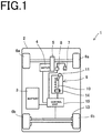
- FIG. 1 is a schematic view showing the configuration of an electric parking brake device according to the present embodiment.
- An electric vehicle 2 which is an example of a vehicle including an electric parking brake device 1 according to the present embodiment, include a battery 3 which is a secondary battery, and a motor for travelling (drive apparatus) 4 which operates using electric power supplied from the battery 3.
- the motor for travelling 4 is connected to drive wheels (front wheels in the present embodiment) 6a via a drive mechanism 5.
- the motor for travelling 4 drives the drive wheels 6a through the drive mechanism 5. Meanwhile, during regeneration operation, the motor for travelling 4 generates electric power upon receipt of rotation from the drive wheels 6a and supplies the electric power to the battery 3.
- the electric parking brake device 1 provided in such an electric vehicle 2 includes a stop lamp switch 8 (an example of pedal state detection means), a shift lever apparatus 9 (an example of shift range detection means for detecting the shift range), a parking brake mechanism 13, an operation switch 14, and a control unit 15 (an example of control means).
- a brake pedal 7 is provided in the electric vehicle 2. Further, the stop lamp switch 8 is provided in the electric vehicle 2 as an example of the pedal state detection means for detecting the operation state of the brake pedal 7, namely whether or not a driver depresses the brake pedal 7.
- the stop lamp switch 8 is a switch for turning a stop lamp (not shown) on when the brake pedal 7 is depressed and turning the stop lamp off when the brake pedal 7 is not depressed.
- the state in which the stop lamp switch 8 is turned on or off can be detected by the control unit 15, which will be described later.
- the control unit 15 can easily determine whether or not the brake pedal 7 is depressed by determining whether or not the stop lamp switch 8 is on or off.
- the pedal state detection means is not limited to the stop lamp switch 8 and may be any of other devices which can detect whether or not the brake pedal is depressed.
- the pedal state detection means may be a brake switch.
- the brake switch is a switch which turns on when the brake pedal 7 is depressed and turns off when the brake pedal 7 is not depressed.
- Another example of the pedal state detection means is a means which uses an oil pressure sensor for detecting the oil pressure of the brake and which determines whether or not the brake pedal 7 is depressed by determining whether or not the oil pressure is equal to or higher than a predetermined pressure.
- Still another example of the pedal state detection means is a means which uses a stroke sensor provided for the brake pedal 7 and which determines whether or not the brake pedal 7 is depressed by determining whether or not the amount of stroke is equal to or greater than a predetermined amount.
- the shift lever apparatus 9 is provided in the electric vehicle 2.
- the shift lever apparatus 9 includes a shift lever 11 which moves along a straight shift path 10. When the driver operates and moves the shift lever 11 to a desired shift range, the operation state of the motor for travelling 4 is switched.
- the shift lever apparatus 9 has, as shift ranges, a drive range (D range), a regeneration range (B range; also called “brake range”), a reverse range (R range), a neutral range (N range), and a parking range (P range).
- D range the electric vehicle 2 travels forward through use of the power of the motor for travelling 4.
- B range the electric vehicle 2 travels forward as in the case of the D range; however, the braking force generated as a result of regeneration braking by the motor for travelling 4 is larger than that in the D range. Namely, when the accelerator pedal is returned, a greater deceleration is attained as compared with the D range.
- the electric vehicle 2 travels backward.
- the N range i.e., in a neutral state
- the power of the motor for travelling 4 is not transmitted to the drive wheels 6a.
- P range the drive wheels 6a are fixed so as to prevent the electric vehicle 2 from moving.
- the shift ranges i.e., the P range, the R range, the B range, the N range, and the D range, are disposed, along a straight line, in this order from the front side of the electric vehicle 2.
- the shift lever apparatus 9 includes a position sensor (not shown) for detecting the position of the shift lever 11.
- the shift range in which the shift lever 11 is located can be detected by the control unit 15 to be described later.
- the shift lever apparatus 9 configured to allow the control unit 15 to detect the shift range of the shift lever 11 corresponds to the shift range detection means in claims.
- the parking brake mechanism 13 is a mechanism which can bring rear wheels 6b (vehicle wheels) into a braked state or a braking-released state.
- the parking brake mechanism 13 includes electric motors (not shown) which operate on the basis of a control signal from the control unit 15, and brake mechanisms (not shown) which apply braking forces to the rear wheels 6b as a result of operation of the electric motors.
- the operation switch 14 is a switch used for switching the parking brake mechanism 13 to a braking state or a braking-released state.
- the operation switch 14 is disposed, for example, near the shift lever apparatus 9 and is composed of a single momentary switch (seesaw switch).
- the momentary switch is a switch configured such that it can be switched to two positions; i.e., a braking position and a braking-releasing position, by an operation of pushing (pulling) one side of a knob or the like which provides a seesaw operation.
- the operation switch 14 has a configuration which allows the driver to switch the operation switch 14 to either of at least two positions; i.e., the braking position and the braking-releasing position.
- the operation switch 14 is configured to allow the control unit 15, which will be described later, to detect the position (the braking position or the braking-releasing position) to which the operation switch 14 is switched.
- the control unit 15 is configured as, for example, a built-in electronic device or an LSI device in which a microprocessor, a ROM, a RAM, etc., are integrated, and is connected to a communication line of an in-vehicle network provided in the vehicle.
- various well known electronic controllers such as a brake controller, a transmission controller, a vehicle stability controller, an air-conditioner controller, and an electrical equipment controller, are connected to the in-vehicle network such that they can communicate with one another.
- the control of the parking brake mechanism 13 by the control unit 15 may be realized by an electronic circuit (hardware) or software.
- the control unit 15 which is connected to the stop lamp switch 8, the shift lever apparatus 9, the parking brake mechanism 13, and the operation switch 14, can detect their states and control them in accordance with their operation states.
- the driver When the driver brings the parking brake mechanism 13 into the braking state, the driver switches the operation switch 14 to the braking position. When the driver brings the parking brake mechanism 13 into the braking-released state, the driver switches the operation switch 14 to the braking-releasing position.
- control unit 15 When the operation switch 14 is operated as described above, the control unit 15 performs control of bringing the parking brake mechanism 13 into the braking state or the braking-released state on the basis of the state of the brake pedal 7 and the shift range of the shift lever 11.
- FIG. 2 is a flowchart showing the processing of the electric parking brake device 1 of the present embodiment.
- the control unit 15 performs the following processing every time the driver operates the operation switch 14 for switching to the braking-releasing position. First, the control unit 15 determines whether or not the parking brake mechanism 13 is in the braking-released state (step S1). In the case where the parking brake mechanism 13 is in the braking-released state (step S1; Yes), the control unit 15 determines that the parking brake mechanism 13 is already in the braking-released state and ends the processing (step S2).
- step S3 the control unit 15 determines whether or not the brake pedal 7 is depressed. In the present embodiment, the control unit 15 determines that the brake pedal 7 is depressed if the stop lamp switch 8 is on, and determines that the brake pedal 7 is not depressed if the stop lamp switch 8 is off.
- step S4 the control unit 15 brings the parking brake mechanism 13 into the braking-released state. Namely, in response to the driver's operation of switching the operation switch 14 to the braking-releasing position, the control unit 15 brings the parking brake mechanism 13 into the braking-released state. Since the control unit 15 brings the parking brake mechanism 13 into the braking-released state on the condition that the parking brake mechanism 13 is in the braking state and the brake pedal 7 is depressed, the braking of the parking brake mechanism 13 can be released in a safe state in which the electric vehicle 2 is stopped.
- step S5 the control unit 15 determines whether or not the shift range is the P range.
- the control unit 15 determines whether or not the shift range of the shift lever 11 is the P range through use of the position sensor of the shift lever apparatus 9,
- the control unit 15 brings the parking brake mechanism 13 into the braking-released state (step S4). Namely, in response to the driver's operation of switching the operation switch 14 to the braking-releasing position, the control unit 15 brings the parking brake mechanism 13 into the braking-released state. Since the control unit 15 brings the parking brake mechanism 13 into the braking-released state on the condition that the parking brake mechanism 13 is in the braking state and the shift range is the P range although the brake pedal 7 is not depressed, the braking of the parking brake mechanism 13 can be released in a safe state in which the electric vehicle 2 is stopped.
- step S6 the control unit 15 does not bring the parking brake mechanism 13 into the braking-released state. Namely, despite the driver's operation of switching the operation switch 14 to the braking-releasing position, the control unit 15 does not bring the parking brake mechanism 13 into the braking-released state and maintains the braking state. By performing such a control, it is possible to prevent the electric vehicle 2 from moving immediately after the braking of the parking brake mechanism 13 is released in response to the driver's operation.
- the control unit 15 can bring the parking brake mechanism 13 into the braking-released state, on the condition that the shift range is the P range (step S5; Yes), even in the case where the parking brake mechanism 13 is in the braking state (step S1; No) and the control unit 15 determines that the brake pedal 7 is not depressed (step S3; No), despite the brake pedal 7 being depressed, because of a failure of the stop lamp switch 8 used for determination of depressing of the brake pedal 7. As a result, it is possible to avoid the necessity of forcing the driver to manually bring the parking brake mechanism into the braking-released state.
- the control unit 15 brings the parking brake mechanism 13 into the braking-released state on the condition that the shift range is the P range. Namely, it is possible to meet a driver's desire to cancel the braking of the parking brake mechanism 13 in the state in which the brake pedal 7 is not depressed, because safety can be secured even when the parking brake mechanism 13 is brought into the braking-released state.
- the electric parking brake mechanism determines whether or not the shift range is the P range (step S5) in the case where the brake pedal 7 is not depressed (step S3; No). However, the electric parking brake mechanism may prompt the driver to depress the brake pedal 7.
- FIG. 3 is a flowchart showing the processing of an electric parking brake device 1 according to the present embodiment.
- the configuration of the electric parking brake device 1 according to the present embodiment is identical with that of the first embodiment.
- the description of the processing which is the same as that in the first embodiment will not be repeated, and the processing different from that in the first embodiment will be described.
- the control unit 15 performs the following processing every time the driver operates the operation switch 14 for switching to the braking-releasing position.
- the processing of step S1 to step S3 and the processing of step S4 (performed in the case where the result of the determination in step S3 is "Yes") are the same as those in the first embodiment.
- the control unit 15 provides a piece of information for causing the driver to depress the brake pedal (hereinafter the piece of information will be also referred to as a "braking prompting message") (step S10).
- the control unit 15 causes an informing means provided in the electric vehicle 2 to provide the braking prompting message.
- the informing means include an acoustic device, such as a speaker, for generating a sound within the electric vehicle 2 and an information display device such as a liquid crystal display.
- the braking prompting message is a piece of information for instructing the driver to depress the brake pedal 7.
- the information is a piece of information which can be recognized through the driver's sense such as the sense of hearing and the sense of sight; for example, a voice or character information for conveying a message "Please depress the brake pedal.”
- the braking prompting message is stored as electronic data in, for example, a storage device of the acoustic device or the information display device in advance, and is produced from the acoustic device or is displayed on the information display device on the basis of the control signal from the control unit 15.
- step S11 After elapse of a predetermined period of time, for example, after providing the braking prompting message, the control unit 15 again determines whether or not the brake pedal 7 is depressed (step S11). In the case where the brake pedal 7 is depressed (step S11; Yes), the control unit 15 brings the parking brake mechanism 13 into the braking-released state (step S4).
- step S5 determines whether or not the shift range is the P range (step S5). In accordance with the result of the determination, the control unit 15 cancels the braking of the parking brake mechanism 13 (step S5; Yes to step S4) or maintains the braking (step S5; No to step S6).
- step S11 the re-determination as to whether or not the brake pedal 7 is depressed (step S11) is performed only one time.
- the present invention is not limited to such an embodiment.
- the step S10 for providing the braking prompting message may be repeated again. This repetition may be continued until the brake pedal 7 is depressed or until the number of times of repetition reaches a predetermined number.
- the parking brake mechanism 13 in the case where the parking brake mechanism 13 is in the braking state (step S1; No) and the brake pedal 7 is not depressed (step S3; No), the braking prompting message is provided to the driver so as to prompt the driver to depress the brake pedal 7.
- the parking brake mechanism 13 can be brought into the braking-released state in a safe state in which the electric vehicle 2 does not start moving, irrespective of whether or not the shift range is the P range.
- an electric parking brake mechanism which determines the case where the brake pedal 7 is depressed but the stop lamp switch 8 (the pedal state detection means) used for determining whether or not the brake pedal 7 is depressed is broken.
- An example of the failure of the stop lamp switch 8 is a failure in which the switch is locked in the off state.
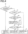
- FIG. 4 is a flowchart showing the processing of an electric parking brake device 1 according to the present embodiment.
- the configuration of the electric parking brake device 1 according to the present embodiment is identical with that of the first embodiment.
- the description of the processing which is the same as that in the first embodiment will not be repeated, and the processing different from that in the first embodiment will be described.
- the control unit 15 performs the following processing every time the driver operates the operation switch 14 for switching to the braking-releasing position.
- the processing of step S1 to step S3 and the processing of step S4 (performed in the case where the result of the determination in step S3 is "Yes") are the same as those in the first embodiment.
- step S20 determines whether or not the pedal state detection means is broken. Specifically, two or more means for detecting that the brake pedal 7 is depressed are used, and, when the results of the detections by the two or more means are inconsistent with one another, the control unit 15 determines that the pedal state detection means is broken.
- an oil pressure sensor for the brake and the stop lamp switch 8 are used as the pedal state detection means.
- the control unit 15 determines that the pedal state detection means is broken.
- the brake oil pressure is equal to or higher than the predetermined threshold, it is considered that the brake pedal 7 is depressed and the brake functions.
- the stop lamp switch 8 should be turned on when the brake pedal 7 is depressed.
- the control unit 15 determines that the pedal state detection means is broken.
- step S21 the control unit 15 provides, through use of the informing means, the driver with a piece of information for causing the driver to change the shift range of the shift lever to the P range (the parking range) (hereinafter the piece of information will be also referred to as a "parking prompting message") (step S21).
- the parking prompting message is a piece of information for instructing the driver to change the shift range of the shift lever 11 to the P range.
- the information is a piece of information which can be recognized through the driver's sense such as the sense of hearing or the sense of sight; for example, a voice or character information for conveying a message "Please move the shift lever to the P range.”
- the parking prompting message is stored as electronic data in, for example, a storage device of the acoustic device or the information display device in advance, and is produced from the acoustic device or is displayed on the information display device on the basis of the control signal from the control unit 15.
- the control unit 15 determines whether or not the shift range is the P range (step S5). In accordance with the result of the determination, the control unit 15 cancels the braking of the parking brake mechanism 13 (step S5; Yes to step S4) or maintains the braking (step S5; No to step S6).
- the parking prompting message is provided one time.
- the present invention is not limited to such an embodiment.
- the step S21 for providing the parking prompting message may be repeated again. This repetition may be continued until the shift range becomes the P range or until the number of times of repetition reaches a predetermined number.
- step S1; No the parking brake mechanism 13 is in the braking state
- step S3; Yes the control unit 15 determines that the brake pedal 7 is not depressed, because of a failure of the pedal state detection means. In this case, the driver is prompted to quickly change the shift range to the P range.
- the shift lever apparatus 9 to which the slide-type shift lever 11 movable to the different shift ranges is applied is shown as an example.
- the shift lever apparatus is not limited thereto.
- the shift lever apparatus may be a so-called momentary-type shift lever apparatus.
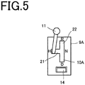
- FIG. 5 is a schematic view of a shift lever apparatus according to the present embodiment.
- a shift lever apparatus 9A includes a shift lever 11, a shift path 10A for guiding the movement of the shift lever 11, urging means (not shown) for always urging the shift lever 11 toward a predetermined neutral position, and detection means (not shown), such as a switch, a sensor, or the like, for detecting the operation of the shift lever 11.
- the shift lever apparatus 9A is of a so-called shift-by-wire type, and is called a momentary-type or a joystick-type.
- the shift lever 11 is located at the neutral position H in an ordinary time.
- the shift lever 11 is configured such that the shift lever 11 can move along the shift path 10A in accordance with a driver's operation, and can be returned to the neutral position by an operator's operation or the urging force of the urging means.
- the shift path 10A has a plurality of grooves which can guide the shift lever 11 to a plurality of positions.
- the shift path 10A is formed such that the plurality of grooves can guide the shift lever 11 to an arbitrary position in accordance with the drive's operation.
- the shift path 10A has a first groove 21 extending from the neutral position H toward one side and a second groove 22 extending in the front-rear direction from the end of the first groove 21.
- the detection means of the shift lever apparatus 9A detects a movement of the shift lever 11, the detection means determines the range to which the shift lever 11 has moved. Specifically, when the shift lever 11 has been moved to the end of the first groove 21 (a central portion of the second groove 22), the detection means determines that the shift lever 11 is in the N range. When the shift lever 11 has been moved to the forward end of the second groove 22, the detection means determines that the shift lever 11 is in the R range. When the shift lever 11 has been moved to the rear end of the second groove 22, the detection means determines that the shift lever 11 is in the D range. Then, the detection means sends to the control unit 15 a piece of information representing the detected shift range of the shift lever 11.
- an electric parking brake mechanism including such a momentary-type shift lever apparatus 9A brings the parking brake mechanism 13 into the braking state or the braking-released state in accordance with the detected shift range and the depression of the brake pedal 9.
- the electric parking brake mechanism according to the present embodiment achieves an action and effects similar to those of the first through third embodiments.
- the present invention can be used in the industrial field of automobiles.
Landscapes
- Engineering & Computer Science (AREA)
- Mechanical Engineering (AREA)
- Transportation (AREA)
- Regulating Braking Force (AREA)
- Braking Elements And Transmission Devices (AREA)
- Valves And Accessory Devices For Braking Systems (AREA)
Claims (4)
- Elektrische Feststellbremsenvorrichtung (1), die aufweist:Pedalzustand-Erfassungsmittel (8), um einen Betätigungszustand eines Bremspedals zu erfassen;Schaltbereich-Erfassungsmittel (9), um einen Schaltbereich eines Schalthebels zu erfassen;einen Feststellbremsenmechanismus (13), der ein Rad in einen gebremsten Zustand oder einen Zustand mit gelöster Bremse bringen kann;einen Betätigungsschalter (14), um den Feststellbremsenmechanismus in einen gebremsten Zustand oder einen Zustand mit gelöster Bremse umzuschalten;Steuermittel (15), um einen Bremsvorgang des Feststellbremsenmechanismus gemäß einer Betätigung des Betätigungsschalters zu steuern; undInformationsmittel, um einem Fahrer eine Information bereitzustellen,wobei, wenn sich der Feststellbremsenmechanismus im Bremszustand befindet, und der Bestätigungsschalter betätigt wird, um in den Zustand mit gelöster Bremse umzuschalten, das Steuermittel den Feststellbremsenmechanismus in den Zustand mit gelöster Bremse unter der Bedingung bringt, dass das Steuermittel mittels des Pedalzustand-Erfassungsmittels erfasst, dass das Bremspedal nicht heruntergedrückt ist und weiterhin mit dem Schaltbereich-Erfassungsmittel erfasst, dass der Schaltbereich des Schalthebels sich in einem Parkbereich befindet, und bestimmt, ob das Pedalzustand-Erfassungsmittel beschädigt ist oder nicht, und in dem Fall, in dem das Pedalzustand-Erfassungsmittel beschädigt ist, durch die Verwendung des Informationsmittels dem Fahrer eine Information bereitstellt, um den Fahrer dazu zu veranlassen, den Schaltbereich des Schalthebels in den Parkbereich zu wechseln.
- Elektrische Feststellbremsenvorrichtung nach Anspruch 1,
wobei, wenn das Steuermittel mittels des Pedalzustand-Erfassungsmittels erfasst, dass das Bremspedal nicht heruntergedrückt ist, das Steuermittel dem Fahrer eine Information bereitstellt, um den Fahrer zu veranlassen, das Bremspedal herunterzudrücken. - Elektrische Feststellbremsenvorrichtung nach Anspruch 1 oder 2, wobei
das Pedalzustand-Erfassungsmittel einen Stopplampenschalter aufweist, der eine Stopplampe einschaltet, wenn das Bremspedal heruntergedrückt ist, und die Stopplampe ausschaltet, wenn das Bremspedal nicht heruntergedrückt ist, und
das Steuermittel bestimmt, ob das Bremspedal herunter gedrückt ist oder nicht, indem bestimmt wird, ob der Stopplampenschalter an- oder ausgeschaltet ist. - Elektrische Feststellbremsenvorrichtung nach Anspruch 3, wobei das Steuermittel das Informationsmittel dazu veranlasst, dem Fahrer eine Information bereitzustellen, um den Fahrer unter der Bedingung, dass der Druck des Bremsöls gleich oder höher als ein vorbestimmter Grenzwert ist und der Stopplampenschalter ausgeschaltet ist, dazu zu veranlassen, den Schaltbereich des Schalthebels in den Parkbereich zu wechseln.
Applications Claiming Priority (2)
| Application Number | Priority Date | Filing Date | Title |
|---|---|---|---|
| JP2014246218A JP6410038B2 (ja) | 2014-12-04 | 2014-12-04 | 電動パーキングブレーキ装置 |
| PCT/JP2015/078395 WO2016088447A1 (ja) | 2014-12-04 | 2015-10-06 | 電動パーキングブレーキ装置 |
Publications (3)
| Publication Number | Publication Date |
|---|---|
| EP3228509A1 EP3228509A1 (de) | 2017-10-11 |
| EP3228509A4 EP3228509A4 (de) | 2018-06-13 |
| EP3228509B1 true EP3228509B1 (de) | 2019-08-14 |
Family
ID=56091403
Family Applications (1)
| Application Number | Title | Priority Date | Filing Date |
|---|---|---|---|
| EP15866269.2A Active EP3228509B1 (de) | 2014-12-04 | 2015-10-06 | Elektrische feststellbremsenvorrichtung |
Country Status (5)
| Country | Link |
|---|---|
| US (1) | US9975536B2 (de) |
| EP (1) | EP3228509B1 (de) |
| JP (1) | JP6410038B2 (de) |
| CN (1) | CN107000711B (de) |
| WO (1) | WO2016088447A1 (de) |
Families Citing this family (9)
| Publication number | Priority date | Publication date | Assignee | Title |
|---|---|---|---|---|
| FR3067428B1 (fr) * | 2017-06-12 | 2019-07-12 | Foundation Brakes France | Etrier de frein pour vehicule comprenant une unite de commande de freinage |
| JP7115339B2 (ja) * | 2019-01-28 | 2022-08-09 | 株式会社デンソー | シフトレンジ制御装置 |
| CN111391852A (zh) * | 2020-02-29 | 2020-07-10 | 宁波吉利汽车研究开发有限公司 | 一种挡位切换控制方法、装置、电子设备及存储介质 |
| DE102020107548A1 (de) * | 2020-03-19 | 2021-09-23 | Ford Global Technologies Llc | Kraftfahrzeug und Verfahren zum Betreiben eines Kraftfahrzeugs |
| CN112721835A (zh) * | 2021-01-29 | 2021-04-30 | 重庆长安汽车股份有限公司 | 自动挡汽车换挡杆引导装置及方法 |
| CN112776773A (zh) * | 2021-02-27 | 2021-05-11 | 重庆长安汽车股份有限公司 | 一种防溜车安全控制方法、系统及汽车 |
| FR3126113B1 (fr) * | 2021-08-13 | 2024-03-01 | Hitachi Astemo France | Dispositif de frein de stationnement à commande améliorée |
| CN114715106B (zh) * | 2022-04-29 | 2023-04-28 | 广州文远知行科技有限公司 | 刹车切换控制器及刹车切换控制系统 |
| DE102023000237A1 (de) | 2023-01-27 | 2024-05-08 | Mercedes-Benz Group AG | Verfahren zum Lösen einer elektronischen Feststellbremse eines Fahrzeuges mit einer elektrischen Antriebseinheit |
Family Cites Families (19)
| Publication number | Priority date | Publication date | Assignee | Title |
|---|---|---|---|---|
| WO1995003965A1 (en) * | 1993-07-30 | 1995-02-09 | Jose Maria Stigliano | Automatic brake holding system |
| DE10028350A1 (de) * | 2000-06-08 | 2001-12-13 | Siemens Ag | Kombinierte Steuereinrichtung für die Feststellbrems- und Parksperrenfunktion von Kraftfahrzeugen |
| US6891468B2 (en) * | 2002-06-04 | 2005-05-10 | Hi-Tech Transport Electronics Inc. | Vehicle brake monitoring system |
| JP4333305B2 (ja) * | 2003-09-24 | 2009-09-16 | マツダ株式会社 | 電動パーキングブレーキシステム |
| JP4576866B2 (ja) * | 2004-04-12 | 2010-11-10 | トヨタ自動車株式会社 | 車両用ブレーキシステム |
| DE102004039866B3 (de) * | 2004-08-17 | 2006-02-09 | Siemens Ag | Steuersystem für die Feststellbremse einer Bremsanlage eines Kraftfahrzeuges |
| JP4685491B2 (ja) * | 2005-03-31 | 2011-05-18 | 日立オートモティブシステムズ株式会社 | ペダル装置 |
| JP4492485B2 (ja) * | 2005-08-23 | 2010-06-30 | トヨタ自動車株式会社 | 車両の制御装置 |
| JP4466582B2 (ja) * | 2006-02-17 | 2010-05-26 | トヨタ自動車株式会社 | 電動パーキングブレーキ装置 |
| JP4656068B2 (ja) * | 2006-03-24 | 2011-03-23 | アイシン・エィ・ダブリュ株式会社 | 車両のパーキング制御システム |
| DE102006026736A1 (de) * | 2006-06-08 | 2007-12-13 | Siemens Ag | Verfahren und Steueranordnung zum gesteuerten Lösen zumindest einer elektrischen Parkbremse eines Fahrzeuges |
| DE102008016659A1 (de) * | 2008-04-01 | 2009-10-29 | Continental Automotive Gmbh | Sicherheitssteuerung für eine elektrische Parkbremse |
| DE102008018946A1 (de) * | 2008-04-15 | 2009-10-22 | Lucas Automotive Gmbh | Technik zum Lösen einer elektrischen Feststellbremse |
| KR101197417B1 (ko) * | 2010-09-06 | 2012-11-05 | 주식회사 동희산업 | 스톱램프스위치 기능을 구비한 브레이크페달의 변위감지센서 |
| US9428053B2 (en) * | 2011-06-16 | 2016-08-30 | Toyota Jidosha Kabushiki Kaisha | Vehicle control device |
| DE102012010841A1 (de) * | 2012-06-01 | 2013-12-05 | GM Global Technology Operations LLC (n. d. Gesetzen des Staates Delaware) | Verfahren zum Betreiben eines Kraftfahrzeugs |
| CN102795210B (zh) * | 2012-08-15 | 2014-07-02 | 浙江亚太机电股份有限公司 | 一种手动挡车辆电子驻车系统及其起步控制方法 |
| US9409552B2 (en) * | 2012-08-29 | 2016-08-09 | GM Global Technology Operations LLC | Electronic park brake module and system and method for use |
| DE102012219533A1 (de) * | 2012-10-25 | 2014-04-30 | Continental Teves Ag & Co. Ohg | Bremsanlage für Kraftfahrzeuge |
-
2014
- 2014-12-04 JP JP2014246218A patent/JP6410038B2/ja active Active
-
2015
- 2015-10-06 WO PCT/JP2015/078395 patent/WO2016088447A1/ja active Application Filing
- 2015-10-06 EP EP15866269.2A patent/EP3228509B1/de active Active
- 2015-10-06 CN CN201580052422.6A patent/CN107000711B/zh active Active
-
2017
- 2017-03-28 US US15/471,285 patent/US9975536B2/en active Active
Non-Patent Citations (1)
| Title |
|---|
| None * |
Also Published As
| Publication number | Publication date |
|---|---|
| JP6410038B2 (ja) | 2018-10-24 |
| US20170197605A1 (en) | 2017-07-13 |
| CN107000711A (zh) | 2017-08-01 |
| JP2016107769A (ja) | 2016-06-20 |
| EP3228509A4 (de) | 2018-06-13 |
| EP3228509A1 (de) | 2017-10-11 |
| US9975536B2 (en) | 2018-05-22 |
| WO2016088447A1 (ja) | 2016-06-09 |
| CN107000711B (zh) | 2019-12-27 |
Similar Documents
| Publication | Publication Date | Title |
|---|---|---|
| EP3228509B1 (de) | Elektrische feststellbremsenvorrichtung | |
| US9298184B2 (en) | Process and device to enable or disable an automatic driving function | |
| JP6552472B2 (ja) | 停車制御装置 | |
| JP6159873B2 (ja) | 継電器でモータの回転方向を制御する車衝突防止・踏み間違い防止アクセルシステム | |
| JP2016527140A (ja) | 自動車を自律的に運転するための運転者補助装置を操作する方法及び自動車 | |
| WO2015033484A1 (en) | Automatic driving apparatus | |
| JP2013238182A (ja) | 車両用の緊急停止装置 | |
| KR20210040256A (ko) | 운전 지원 장치 및 운전 지원 방법 | |
| CN111788099B (zh) | 用于车辆的辅助系统 | |
| JP2016205454A (ja) | 車両のシフト制御装置 | |
| JP2013233893A (ja) | 走行制御装置 | |
| JP6288448B2 (ja) | 車両のシフト制御装置 | |
| JP6229434B2 (ja) | 車両用制御装置 | |
| EP3505743A1 (de) | System und verfahren zur steuerung eines motors für ein industriefahrzeug | |
| JP5920022B2 (ja) | 車両用ブレーキ装置 | |
| KR20140018165A (ko) | 차량용 변속기 제어 장치 및 방법 | |
| JP2014091483A (ja) | 車両用制御装置 | |
| JP2014155402A (ja) | 電気自動車のモータ制御システム | |
| JP2011225055A (ja) | ストップランプ制御装置 | |
| JP2008013084A (ja) | 自動変速機のレンジ切換制御装置 | |
| JP2021020567A (ja) | 車両停止装置 | |
| JP2006082602A (ja) | 自動ブレーキ補助システム | |
| KR101134919B1 (ko) | 차량의 주행 제어 보조 장치 | |
| JP7223844B2 (ja) | 自動車のアクセルペダルの特性曲線を変更するための方法および自動車用特性曲線変更装置 | |
| JP6206038B2 (ja) | ブレーキランプの制御装置 |
Legal Events
| Date | Code | Title | Description |
|---|---|---|---|
| STAA | Information on the status of an ep patent application or granted ep patent |
Free format text: STATUS: THE INTERNATIONAL PUBLICATION HAS BEEN MADE |
|
| PUAI | Public reference made under article 153(3) epc to a published international application that has entered the european phase |
Free format text: ORIGINAL CODE: 0009012 |
|
| STAA | Information on the status of an ep patent application or granted ep patent |
Free format text: STATUS: REQUEST FOR EXAMINATION WAS MADE |
|
| 17P | Request for examination filed |
Effective date: 20170428 |
|
| AK | Designated contracting states |
Kind code of ref document: A1 Designated state(s): AL AT BE BG CH CY CZ DE DK EE ES FI FR GB GR HR HU IE IS IT LI LT LU LV MC MK MT NL NO PL PT RO RS SE SI SK SM TR |
|
| AX | Request for extension of the european patent |
Extension state: BA ME |
|
| RIN1 | Information on inventor provided before grant (corrected) |
Inventor name: NAKA, MUTSUHIRO Inventor name: WATANABE, NAOKI Inventor name: YAMAMOTO, NAOKI Inventor name: KAWASAKI, TOMOHIRO Inventor name: NAKAGAWA, SHINJI Inventor name: HAYAKAWA, KAZUNORI Inventor name: WAKO, TAKAYUKI |
|
| DAV | Request for validation of the european patent (deleted) | ||
| DAX | Request for extension of the european patent (deleted) | ||
| A4 | Supplementary search report drawn up and despatched |
Effective date: 20180514 |
|
| RIC1 | Information provided on ipc code assigned before grant |
Ipc: B60T 7/12 20060101AFI20180508BHEP Ipc: B60T 7/04 20060101ALI20180508BHEP |
|
| GRAP | Despatch of communication of intention to grant a patent |
Free format text: ORIGINAL CODE: EPIDOSNIGR1 |
|
| STAA | Information on the status of an ep patent application or granted ep patent |
Free format text: STATUS: GRANT OF PATENT IS INTENDED |
|
| INTG | Intention to grant announced |
Effective date: 20190221 |
|
| RAP1 | Party data changed (applicant data changed or rights of an application transferred) |
Owner name: MITSUBISHI JIDOSHA KOGYO KABUSHIKI KAISHA |
|
| GRAS | Grant fee paid |
Free format text: ORIGINAL CODE: EPIDOSNIGR3 |
|
| GRAA | (expected) grant |
Free format text: ORIGINAL CODE: 0009210 |
|
| STAA | Information on the status of an ep patent application or granted ep patent |
Free format text: STATUS: THE PATENT HAS BEEN GRANTED |
|
| RIN1 | Information on inventor provided before grant (corrected) |
Inventor name: NAKAGAWA, SHINJI Inventor name: YAMAMOTO, NAOKI Inventor name: HAYAKAWA, KAZUNORI Inventor name: KAWASAKI, TOMOHIRO Inventor name: WATANABE, NAOKI Inventor name: WAKO, TAKAYUKI Inventor name: NAKA, MUTSUHIRO |
|
| AK | Designated contracting states |
Kind code of ref document: B1 Designated state(s): AL AT BE BG CH CY CZ DE DK EE ES FI FR GB GR HR HU IE IS IT LI LT LU LV MC MK MT NL NO PL PT RO RS SE SI SK SM TR |
|
| REG | Reference to a national code |
Ref country code: GB Ref legal event code: FG4D |
|
| REG | Reference to a national code |
Ref country code: CH Ref legal event code: EP Ref country code: AT Ref legal event code: REF Ref document number: 1166663 Country of ref document: AT Kind code of ref document: T Effective date: 20190815 |
|
| REG | Reference to a national code |
Ref country code: IE Ref legal event code: FG4D |
|
| REG | Reference to a national code |
Ref country code: DE Ref legal event code: R096 Ref document number: 602015036052 Country of ref document: DE |
|
| REG | Reference to a national code |
Ref country code: NL Ref legal event code: MP Effective date: 20190814 |
|
| REG | Reference to a national code |
Ref country code: LT Ref legal event code: MG4D |
|
| PG25 | Lapsed in a contracting state [announced via postgrant information from national office to epo] |
Ref country code: PT Free format text: LAPSE BECAUSE OF FAILURE TO SUBMIT A TRANSLATION OF THE DESCRIPTION OR TO PAY THE FEE WITHIN THE PRESCRIBED TIME-LIMIT Effective date: 20191216 Ref country code: LT Free format text: LAPSE BECAUSE OF FAILURE TO SUBMIT A TRANSLATION OF THE DESCRIPTION OR TO PAY THE FEE WITHIN THE PRESCRIBED TIME-LIMIT Effective date: 20190814 Ref country code: NL Free format text: LAPSE BECAUSE OF FAILURE TO SUBMIT A TRANSLATION OF THE DESCRIPTION OR TO PAY THE FEE WITHIN THE PRESCRIBED TIME-LIMIT Effective date: 20190814 Ref country code: HR Free format text: LAPSE BECAUSE OF FAILURE TO SUBMIT A TRANSLATION OF THE DESCRIPTION OR TO PAY THE FEE WITHIN THE PRESCRIBED TIME-LIMIT Effective date: 20190814 Ref country code: BG Free format text: LAPSE BECAUSE OF FAILURE TO SUBMIT A TRANSLATION OF THE DESCRIPTION OR TO PAY THE FEE WITHIN THE PRESCRIBED TIME-LIMIT Effective date: 20191114 Ref country code: SE Free format text: LAPSE BECAUSE OF FAILURE TO SUBMIT A TRANSLATION OF THE DESCRIPTION OR TO PAY THE FEE WITHIN THE PRESCRIBED TIME-LIMIT Effective date: 20190814 Ref country code: FI Free format text: LAPSE BECAUSE OF FAILURE TO SUBMIT A TRANSLATION OF THE DESCRIPTION OR TO PAY THE FEE WITHIN THE PRESCRIBED TIME-LIMIT Effective date: 20190814 Ref country code: NO Free format text: LAPSE BECAUSE OF FAILURE TO SUBMIT A TRANSLATION OF THE DESCRIPTION OR TO PAY THE FEE WITHIN THE PRESCRIBED TIME-LIMIT Effective date: 20191114 |
|
| REG | Reference to a national code |
Ref country code: AT Ref legal event code: MK05 Ref document number: 1166663 Country of ref document: AT Kind code of ref document: T Effective date: 20190814 |
|
| PG25 | Lapsed in a contracting state [announced via postgrant information from national office to epo] |
Ref country code: ES Free format text: LAPSE BECAUSE OF FAILURE TO SUBMIT A TRANSLATION OF THE DESCRIPTION OR TO PAY THE FEE WITHIN THE PRESCRIBED TIME-LIMIT Effective date: 20190814 Ref country code: LV Free format text: LAPSE BECAUSE OF FAILURE TO SUBMIT A TRANSLATION OF THE DESCRIPTION OR TO PAY THE FEE WITHIN THE PRESCRIBED TIME-LIMIT Effective date: 20190814 Ref country code: RS Free format text: LAPSE BECAUSE OF FAILURE TO SUBMIT A TRANSLATION OF THE DESCRIPTION OR TO PAY THE FEE WITHIN THE PRESCRIBED TIME-LIMIT Effective date: 20190814 Ref country code: GR Free format text: LAPSE BECAUSE OF FAILURE TO SUBMIT A TRANSLATION OF THE DESCRIPTION OR TO PAY THE FEE WITHIN THE PRESCRIBED TIME-LIMIT Effective date: 20191115 Ref country code: IS Free format text: LAPSE BECAUSE OF FAILURE TO SUBMIT A TRANSLATION OF THE DESCRIPTION OR TO PAY THE FEE WITHIN THE PRESCRIBED TIME-LIMIT Effective date: 20191214 Ref country code: AL Free format text: LAPSE BECAUSE OF FAILURE TO SUBMIT A TRANSLATION OF THE DESCRIPTION OR TO PAY THE FEE WITHIN THE PRESCRIBED TIME-LIMIT Effective date: 20190814 |
|
| PG25 | Lapsed in a contracting state [announced via postgrant information from national office to epo] |
Ref country code: TR Free format text: LAPSE BECAUSE OF FAILURE TO SUBMIT A TRANSLATION OF THE DESCRIPTION OR TO PAY THE FEE WITHIN THE PRESCRIBED TIME-LIMIT Effective date: 20190814 |
|
| PG25 | Lapsed in a contracting state [announced via postgrant information from national office to epo] |
Ref country code: RO Free format text: LAPSE BECAUSE OF FAILURE TO SUBMIT A TRANSLATION OF THE DESCRIPTION OR TO PAY THE FEE WITHIN THE PRESCRIBED TIME-LIMIT Effective date: 20190814 Ref country code: IT Free format text: LAPSE BECAUSE OF FAILURE TO SUBMIT A TRANSLATION OF THE DESCRIPTION OR TO PAY THE FEE WITHIN THE PRESCRIBED TIME-LIMIT Effective date: 20190814 Ref country code: EE Free format text: LAPSE BECAUSE OF FAILURE TO SUBMIT A TRANSLATION OF THE DESCRIPTION OR TO PAY THE FEE WITHIN THE PRESCRIBED TIME-LIMIT Effective date: 20190814 Ref country code: AT Free format text: LAPSE BECAUSE OF FAILURE TO SUBMIT A TRANSLATION OF THE DESCRIPTION OR TO PAY THE FEE WITHIN THE PRESCRIBED TIME-LIMIT Effective date: 20190814 Ref country code: DK Free format text: LAPSE BECAUSE OF FAILURE TO SUBMIT A TRANSLATION OF THE DESCRIPTION OR TO PAY THE FEE WITHIN THE PRESCRIBED TIME-LIMIT Effective date: 20190814 Ref country code: PL Free format text: LAPSE BECAUSE OF FAILURE TO SUBMIT A TRANSLATION OF THE DESCRIPTION OR TO PAY THE FEE WITHIN THE PRESCRIBED TIME-LIMIT Effective date: 20190814 |
|
| PG25 | Lapsed in a contracting state [announced via postgrant information from national office to epo] |
Ref country code: CZ Free format text: LAPSE BECAUSE OF FAILURE TO SUBMIT A TRANSLATION OF THE DESCRIPTION OR TO PAY THE FEE WITHIN THE PRESCRIBED TIME-LIMIT Effective date: 20190814 Ref country code: MC Free format text: LAPSE BECAUSE OF FAILURE TO SUBMIT A TRANSLATION OF THE DESCRIPTION OR TO PAY THE FEE WITHIN THE PRESCRIBED TIME-LIMIT Effective date: 20190814 Ref country code: SK Free format text: LAPSE BECAUSE OF FAILURE TO SUBMIT A TRANSLATION OF THE DESCRIPTION OR TO PAY THE FEE WITHIN THE PRESCRIBED TIME-LIMIT Effective date: 20190814 Ref country code: IS Free format text: LAPSE BECAUSE OF FAILURE TO SUBMIT A TRANSLATION OF THE DESCRIPTION OR TO PAY THE FEE WITHIN THE PRESCRIBED TIME-LIMIT Effective date: 20200224 Ref country code: SM Free format text: LAPSE BECAUSE OF FAILURE TO SUBMIT A TRANSLATION OF THE DESCRIPTION OR TO PAY THE FEE WITHIN THE PRESCRIBED TIME-LIMIT Effective date: 20190814 |
|
| REG | Reference to a national code |
Ref country code: CH Ref legal event code: PL |
|
| REG | Reference to a national code |
Ref country code: DE Ref legal event code: R097 Ref document number: 602015036052 Country of ref document: DE |
|
| PLBE | No opposition filed within time limit |
Free format text: ORIGINAL CODE: 0009261 |
|
| STAA | Information on the status of an ep patent application or granted ep patent |
Free format text: STATUS: NO OPPOSITION FILED WITHIN TIME LIMIT |
|
| PG2D | Information on lapse in contracting state deleted |
Ref country code: IS |
|
| PG25 | Lapsed in a contracting state [announced via postgrant information from national office to epo] |
Ref country code: LU Free format text: LAPSE BECAUSE OF NON-PAYMENT OF DUE FEES Effective date: 20191006 Ref country code: CH Free format text: LAPSE BECAUSE OF NON-PAYMENT OF DUE FEES Effective date: 20191031 Ref country code: LI Free format text: LAPSE BECAUSE OF NON-PAYMENT OF DUE FEES Effective date: 20191031 |
|
| 26N | No opposition filed |
Effective date: 20200603 |
|
| REG | Reference to a national code |
Ref country code: BE Ref legal event code: MM Effective date: 20191031 |
|
| PG25 | Lapsed in a contracting state [announced via postgrant information from national office to epo] |
Ref country code: SI Free format text: LAPSE BECAUSE OF FAILURE TO SUBMIT A TRANSLATION OF THE DESCRIPTION OR TO PAY THE FEE WITHIN THE PRESCRIBED TIME-LIMIT Effective date: 20190814 Ref country code: BE Free format text: LAPSE BECAUSE OF NON-PAYMENT OF DUE FEES Effective date: 20191031 |
|
| GBPC | Gb: european patent ceased through non-payment of renewal fee |
Effective date: 20191114 |
|
| PG25 | Lapsed in a contracting state [announced via postgrant information from national office to epo] |
Ref country code: IE Free format text: LAPSE BECAUSE OF NON-PAYMENT OF DUE FEES Effective date: 20191006 Ref country code: GB Free format text: LAPSE BECAUSE OF NON-PAYMENT OF DUE FEES Effective date: 20191114 |
|
| PG25 | Lapsed in a contracting state [announced via postgrant information from national office to epo] |
Ref country code: CY Free format text: LAPSE BECAUSE OF FAILURE TO SUBMIT A TRANSLATION OF THE DESCRIPTION OR TO PAY THE FEE WITHIN THE PRESCRIBED TIME-LIMIT Effective date: 20190814 |
|
| PG25 | Lapsed in a contracting state [announced via postgrant information from national office to epo] |
Ref country code: MT Free format text: LAPSE BECAUSE OF FAILURE TO SUBMIT A TRANSLATION OF THE DESCRIPTION OR TO PAY THE FEE WITHIN THE PRESCRIBED TIME-LIMIT Effective date: 20190814 Ref country code: HU Free format text: LAPSE BECAUSE OF FAILURE TO SUBMIT A TRANSLATION OF THE DESCRIPTION OR TO PAY THE FEE WITHIN THE PRESCRIBED TIME-LIMIT; INVALID AB INITIO Effective date: 20151006 |
|
| PG25 | Lapsed in a contracting state [announced via postgrant information from national office to epo] |
Ref country code: MK Free format text: LAPSE BECAUSE OF FAILURE TO SUBMIT A TRANSLATION OF THE DESCRIPTION OR TO PAY THE FEE WITHIN THE PRESCRIBED TIME-LIMIT Effective date: 20190814 |
|
| PGFP | Annual fee paid to national office [announced via postgrant information from national office to epo] |
Ref country code: FR Payment date: 20230911 Year of fee payment: 9 |
|
| PGFP | Annual fee paid to national office [announced via postgrant information from national office to epo] |
Ref country code: DE Payment date: 20230830 Year of fee payment: 9 |