EP3227506B1 - A roofing, cladding or siding product - Google Patents
A roofing, cladding or siding product Download PDFInfo
- Publication number
- EP3227506B1 EP3227506B1 EP15866038.1A EP15866038A EP3227506B1 EP 3227506 B1 EP3227506 B1 EP 3227506B1 EP 15866038 A EP15866038 A EP 15866038A EP 3227506 B1 EP3227506 B1 EP 3227506B1
- Authority
- EP
- European Patent Office
- Prior art keywords
- module
- layer
- another embodiment
- reinforcement
- layers
- Prior art date
- Legal status (The legal status is an assumption and is not a legal conclusion. Google has not performed a legal analysis and makes no representation as to the accuracy of the status listed.)
- Active
Links
Images








Classifications
-
- E—FIXED CONSTRUCTIONS
- E04—BUILDING
- E04D—ROOF COVERINGS; SKY-LIGHTS; GUTTERS; ROOF-WORKING TOOLS
- E04D1/00—Roof covering by making use of tiles, slates, shingles, or other small roofing elements
- E04D1/12—Roofing elements shaped as plain tiles or shingles, i.e. with flat outer surface
- E04D1/22—Roofing elements shaped as plain tiles or shingles, i.e. with flat outer surface of specified materials not covered by any one of groups E04D1/14 - E04D1/205, or of combinations of materials, where at least one is not covered by any one of groups E04D1/14 - E04D1/205
-
- B—PERFORMING OPERATIONS; TRANSPORTING
- B29—WORKING OF PLASTICS; WORKING OF SUBSTANCES IN A PLASTIC STATE IN GENERAL
- B29C—SHAPING OR JOINING OF PLASTICS; SHAPING OF MATERIAL IN A PLASTIC STATE, NOT OTHERWISE PROVIDED FOR; AFTER-TREATMENT OF THE SHAPED PRODUCTS, e.g. REPAIRING
- B29C41/00—Shaping by coating a mould, core or other substrate, i.e. by depositing material and stripping-off the shaped article; Apparatus therefor
- B29C41/24—Shaping by coating a mould, core or other substrate, i.e. by depositing material and stripping-off the shaped article; Apparatus therefor for making articles of indefinite length
- B29C41/28—Shaping by coating a mould, core or other substrate, i.e. by depositing material and stripping-off the shaped article; Apparatus therefor for making articles of indefinite length by depositing flowable material on an endless belt
-
- B—PERFORMING OPERATIONS; TRANSPORTING
- B29—WORKING OF PLASTICS; WORKING OF SUBSTANCES IN A PLASTIC STATE IN GENERAL
- B29C—SHAPING OR JOINING OF PLASTICS; SHAPING OF MATERIAL IN A PLASTIC STATE, NOT OTHERWISE PROVIDED FOR; AFTER-TREATMENT OF THE SHAPED PRODUCTS, e.g. REPAIRING
- B29C41/00—Shaping by coating a mould, core or other substrate, i.e. by depositing material and stripping-off the shaped article; Apparatus therefor
- B29C41/24—Shaping by coating a mould, core or other substrate, i.e. by depositing material and stripping-off the shaped article; Apparatus therefor for making articles of indefinite length
- B29C41/32—Making multilayered or multicoloured articles
-
- B—PERFORMING OPERATIONS; TRANSPORTING
- B29—WORKING OF PLASTICS; WORKING OF SUBSTANCES IN A PLASTIC STATE IN GENERAL
- B29C—SHAPING OR JOINING OF PLASTICS; SHAPING OF MATERIAL IN A PLASTIC STATE, NOT OTHERWISE PROVIDED FOR; AFTER-TREATMENT OF THE SHAPED PRODUCTS, e.g. REPAIRING
- B29C48/00—Extrusion moulding, i.e. expressing the moulding material through a die or nozzle which imparts the desired form; Apparatus therefor
- B29C48/03—Extrusion moulding, i.e. expressing the moulding material through a die or nozzle which imparts the desired form; Apparatus therefor characterised by the shape of the extruded material at extrusion
- B29C48/07—Flat, e.g. panels
-
- B—PERFORMING OPERATIONS; TRANSPORTING
- B29—WORKING OF PLASTICS; WORKING OF SUBSTANCES IN A PLASTIC STATE IN GENERAL
- B29C—SHAPING OR JOINING OF PLASTICS; SHAPING OF MATERIAL IN A PLASTIC STATE, NOT OTHERWISE PROVIDED FOR; AFTER-TREATMENT OF THE SHAPED PRODUCTS, e.g. REPAIRING
- B29C48/00—Extrusion moulding, i.e. expressing the moulding material through a die or nozzle which imparts the desired form; Apparatus therefor
- B29C48/03—Extrusion moulding, i.e. expressing the moulding material through a die or nozzle which imparts the desired form; Apparatus therefor characterised by the shape of the extruded material at extrusion
- B29C48/12—Articles with an irregular circumference when viewed in cross-section, e.g. window profiles
-
- B—PERFORMING OPERATIONS; TRANSPORTING
- B32—LAYERED PRODUCTS
- B32B—LAYERED PRODUCTS, i.e. PRODUCTS BUILT-UP OF STRATA OF FLAT OR NON-FLAT, e.g. CELLULAR OR HONEYCOMB, FORM
- B32B27/00—Layered products comprising a layer of synthetic resin
- B32B27/06—Layered products comprising a layer of synthetic resin as the main or only constituent of a layer, which is next to another layer of the same or of a different material
-
- B—PERFORMING OPERATIONS; TRANSPORTING
- B32—LAYERED PRODUCTS
- B32B—LAYERED PRODUCTS, i.e. PRODUCTS BUILT-UP OF STRATA OF FLAT OR NON-FLAT, e.g. CELLULAR OR HONEYCOMB, FORM
- B32B5/00—Layered products characterised by the non- homogeneity or physical structure, i.e. comprising a fibrous, filamentary, particulate or foam layer; Layered products characterised by having a layer differing constitutionally or physically in different parts
- B32B5/18—Layered products characterised by the non- homogeneity or physical structure, i.e. comprising a fibrous, filamentary, particulate or foam layer; Layered products characterised by having a layer differing constitutionally or physically in different parts characterised by features of a layer of foamed material
-
- E—FIXED CONSTRUCTIONS
- E04—BUILDING
- E04D—ROOF COVERINGS; SKY-LIGHTS; GUTTERS; ROOF-WORKING TOOLS
- E04D1/00—Roof covering by making use of tiles, slates, shingles, or other small roofing elements
- E04D1/26—Strip-shaped roofing elements simulating a repetitive pattern, e.g. appearing as a row of shingles
-
- E—FIXED CONSTRUCTIONS
- E04—BUILDING
- E04D—ROOF COVERINGS; SKY-LIGHTS; GUTTERS; ROOF-WORKING TOOLS
- E04D1/00—Roof covering by making use of tiles, slates, shingles, or other small roofing elements
- E04D1/28—Roofing elements comprising two or more layers, e.g. for insulation
-
- E—FIXED CONSTRUCTIONS
- E04—BUILDING
- E04F—FINISHING WORK ON BUILDINGS, e.g. STAIRS, FLOORS
- E04F13/00—Coverings or linings, e.g. for walls or ceilings
- E04F13/07—Coverings or linings, e.g. for walls or ceilings composed of covering or lining elements; Sub-structures therefor; Fastening means therefor
- E04F13/08—Coverings or linings, e.g. for walls or ceilings composed of covering or lining elements; Sub-structures therefor; Fastening means therefor composed of a plurality of similar covering or lining elements
- E04F13/0864—Coverings or linings, e.g. for walls or ceilings composed of covering or lining elements; Sub-structures therefor; Fastening means therefor composed of a plurality of similar covering or lining elements composed of superposed elements which overlap each other and of which the flat outer surface includes an acute angle with the surface to cover
-
- E—FIXED CONSTRUCTIONS
- E04—BUILDING
- E04F—FINISHING WORK ON BUILDINGS, e.g. STAIRS, FLOORS
- E04F13/00—Coverings or linings, e.g. for walls or ceilings
- E04F13/07—Coverings or linings, e.g. for walls or ceilings composed of covering or lining elements; Sub-structures therefor; Fastening means therefor
- E04F13/08—Coverings or linings, e.g. for walls or ceilings composed of covering or lining elements; Sub-structures therefor; Fastening means therefor composed of a plurality of similar covering or lining elements
- E04F13/0866—Coverings or linings, e.g. for walls or ceilings composed of covering or lining elements; Sub-structures therefor; Fastening means therefor composed of a plurality of similar covering or lining elements composed of several layers, e.g. sandwich panels or layered panels
-
- E—FIXED CONSTRUCTIONS
- E04—BUILDING
- E04F—FINISHING WORK ON BUILDINGS, e.g. STAIRS, FLOORS
- E04F13/00—Coverings or linings, e.g. for walls or ceilings
- E04F13/07—Coverings or linings, e.g. for walls or ceilings composed of covering or lining elements; Sub-structures therefor; Fastening means therefor
- E04F13/08—Coverings or linings, e.g. for walls or ceilings composed of covering or lining elements; Sub-structures therefor; Fastening means therefor composed of a plurality of similar covering or lining elements
- E04F13/16—Coverings or linings, e.g. for walls or ceilings composed of covering or lining elements; Sub-structures therefor; Fastening means therefor composed of a plurality of similar covering or lining elements of fibres or chips, e.g. bonded with synthetic resins, or with an outer layer of fibres or chips
-
- E—FIXED CONSTRUCTIONS
- E04—BUILDING
- E04F—FINISHING WORK ON BUILDINGS, e.g. STAIRS, FLOORS
- E04F13/00—Coverings or linings, e.g. for walls or ceilings
- E04F13/07—Coverings or linings, e.g. for walls or ceilings composed of covering or lining elements; Sub-structures therefor; Fastening means therefor
- E04F13/08—Coverings or linings, e.g. for walls or ceilings composed of covering or lining elements; Sub-structures therefor; Fastening means therefor composed of a plurality of similar covering or lining elements
- E04F13/16—Coverings or linings, e.g. for walls or ceilings composed of covering or lining elements; Sub-structures therefor; Fastening means therefor composed of a plurality of similar covering or lining elements of fibres or chips, e.g. bonded with synthetic resins, or with an outer layer of fibres or chips
- E04F13/165—Coverings or linings, e.g. for walls or ceilings composed of covering or lining elements; Sub-structures therefor; Fastening means therefor composed of a plurality of similar covering or lining elements of fibres or chips, e.g. bonded with synthetic resins, or with an outer layer of fibres or chips with an outer layer imitating natural stone, brick work, tiled surface or the like
-
- B—PERFORMING OPERATIONS; TRANSPORTING
- B29—WORKING OF PLASTICS; WORKING OF SUBSTANCES IN A PLASTIC STATE IN GENERAL
- B29C—SHAPING OR JOINING OF PLASTICS; SHAPING OF MATERIAL IN A PLASTIC STATE, NOT OTHERWISE PROVIDED FOR; AFTER-TREATMENT OF THE SHAPED PRODUCTS, e.g. REPAIRING
- B29C48/00—Extrusion moulding, i.e. expressing the moulding material through a die or nozzle which imparts the desired form; Apparatus therefor
- B29C48/001—Combinations of extrusion moulding with other shaping operations
- B29C48/0013—Extrusion moulding in several steps, i.e. components merging outside the die
- B29C48/0014—Extrusion moulding in several steps, i.e. components merging outside the die producing flat articles having components brought in contact outside the extrusion die
-
- B—PERFORMING OPERATIONS; TRANSPORTING
- B29—WORKING OF PLASTICS; WORKING OF SUBSTANCES IN A PLASTIC STATE IN GENERAL
- B29C—SHAPING OR JOINING OF PLASTICS; SHAPING OF MATERIAL IN A PLASTIC STATE, NOT OTHERWISE PROVIDED FOR; AFTER-TREATMENT OF THE SHAPED PRODUCTS, e.g. REPAIRING
- B29C48/00—Extrusion moulding, i.e. expressing the moulding material through a die or nozzle which imparts the desired form; Apparatus therefor
- B29C48/03—Extrusion moulding, i.e. expressing the moulding material through a die or nozzle which imparts the desired form; Apparatus therefor characterised by the shape of the extruded material at extrusion
- B29C48/13—Articles with a cross-section varying in the longitudinal direction, e.g. corrugated pipes
-
- B—PERFORMING OPERATIONS; TRANSPORTING
- B29—WORKING OF PLASTICS; WORKING OF SUBSTANCES IN A PLASTIC STATE IN GENERAL
- B29C—SHAPING OR JOINING OF PLASTICS; SHAPING OF MATERIAL IN A PLASTIC STATE, NOT OTHERWISE PROVIDED FOR; AFTER-TREATMENT OF THE SHAPED PRODUCTS, e.g. REPAIRING
- B29C48/00—Extrusion moulding, i.e. expressing the moulding material through a die or nozzle which imparts the desired form; Apparatus therefor
- B29C48/16—Articles comprising two or more components, e.g. co-extruded layers
- B29C48/18—Articles comprising two or more components, e.g. co-extruded layers the components being layers
- B29C48/21—Articles comprising two or more components, e.g. co-extruded layers the components being layers the layers being joined at their surfaces
-
- B—PERFORMING OPERATIONS; TRANSPORTING
- B29—WORKING OF PLASTICS; WORKING OF SUBSTANCES IN A PLASTIC STATE IN GENERAL
- B29C—SHAPING OR JOINING OF PLASTICS; SHAPING OF MATERIAL IN A PLASTIC STATE, NOT OTHERWISE PROVIDED FOR; AFTER-TREATMENT OF THE SHAPED PRODUCTS, e.g. REPAIRING
- B29C48/00—Extrusion moulding, i.e. expressing the moulding material through a die or nozzle which imparts the desired form; Apparatus therefor
- B29C48/25—Component parts, details or accessories; Auxiliary operations
- B29C48/30—Extrusion nozzles or dies
- B29C48/303—Extrusion nozzles or dies using dies or die parts movable in a closed circuit, e.g. mounted on movable endless support
-
- B—PERFORMING OPERATIONS; TRANSPORTING
- B29—WORKING OF PLASTICS; WORKING OF SUBSTANCES IN A PLASTIC STATE IN GENERAL
- B29L—INDEXING SCHEME ASSOCIATED WITH SUBCLASS B29C, RELATING TO PARTICULAR ARTICLES
- B29L2031/00—Other particular articles
- B29L2031/10—Building elements, e.g. bricks, blocks, tiles, panels, posts, beams
- B29L2031/104—Tiles
-
- B—PERFORMING OPERATIONS; TRANSPORTING
- B29—WORKING OF PLASTICS; WORKING OF SUBSTANCES IN A PLASTIC STATE IN GENERAL
- B29L—INDEXING SCHEME ASSOCIATED WITH SUBCLASS B29C, RELATING TO PARTICULAR ARTICLES
- B29L2031/00—Other particular articles
- B29L2031/10—Building elements, e.g. bricks, blocks, tiles, panels, posts, beams
- B29L2031/108—Roofs
-
- B—PERFORMING OPERATIONS; TRANSPORTING
- B32—LAYERED PRODUCTS
- B32B—LAYERED PRODUCTS, i.e. PRODUCTS BUILT-UP OF STRATA OF FLAT OR NON-FLAT, e.g. CELLULAR OR HONEYCOMB, FORM
- B32B2266/00—Composition of foam
- B32B2266/02—Organic
- B32B2266/0214—Materials belonging to B32B27/00
-
- B—PERFORMING OPERATIONS; TRANSPORTING
- B32—LAYERED PRODUCTS
- B32B—LAYERED PRODUCTS, i.e. PRODUCTS BUILT-UP OF STRATA OF FLAT OR NON-FLAT, e.g. CELLULAR OR HONEYCOMB, FORM
- B32B2419/00—Buildings or parts thereof
- B32B2419/06—Roofs, roof membranes
Definitions
- the present invention relates to roofing, cladding, and/or siding products and assemblies of such products, for installation onto a building surface.
- the present invention additionally relates to systems and methods of manufacture of roofing, cladding, and/or siding products.
- roofing, cladding and/or siding products there are a variety of known roofing, cladding and/or siding products, each of which have particular appearance and performance characteristics for installing onto building surfaces according to a user's preference.
- Well-known products include asphalt shingles, slate, tiles, concrete tiles, corrugated profiles, etc.
- US 2007/039274 A1 discloses a roofing shingle includes a buttlap portion with a butt edge and a headlap portion with a head edge.
- the roofing shingle includes a coated mat which is a roofing mat coated with an organic-based coating material.
- the roofing shingle also includes a water impermeable sheet adjacent to the coated mat.
- US 2011/214372 A1 discussed an insulated siding member including an attachment channel and an interlocking configuration located on the siding panel.
- the interlocking configuration comprises a tongue located at a first end of the siding panel and a groove located at a second end of the siding panel.
- the tongue of a first siding member fits within said groove of a second siding member.
- An upper lip and an upper surface are located on each side of the groove, and a lower slot and a lower surface are located on each side of the tongue.
- the lower slot and the lower surface extend a length outward from the tongue.
- the siding module may be fabricated out of an extruded vinyl composite, such as fiberglass reinforcement.
- the document US 2010/037548 A1 also discloses a roofing module.
- the present invention is according to claim 1.
- the module comprises a plurality of formed surfaces molded along the length of the module.
- the layer so formed comprises at least 60% w/w filler and/or reinforcement.
- the layer comprises about 60% to about 95% w/w filler and/or reinforcement.
- the layer comprises at least about 5% w/w reinforcement.
- the layer comprises about 5% to about 30% w/w reinforcement.
- the layer comprises at least about 80% filler and at least about 10% reinforcement.
- the layer comprises one or more of the following polymers:
- the filler comprises one or more of the following:
- the reinforcement comprises one or more non-conductive natural or synthetic fibres.
- the reinforcement comprises one or more of the following:
- the layer further comprises one or more of the following:
- the filler and/or reinforcement is about 40%, 41%, 42%, 43%, 44%, 45%, 46%, 47%, 48%, 49%, 50%, 51%, 52%, 53%, 54%, 55%, 56%, 57%, 58%, 59%, 60%, 61%, 62%, 63%, 64%, 65%, 66%, 67%, 68%, 69%, 70%, 71%, 72%, 73%, 74%, 75%, 76%, 77%, 78%, 79%, 80%, 81%, 82%, 83%, 84%, 85%, 86%, 87%, 88%, 89%, 90%, 91%, 92%, 93%, 94%, 95 % or may be numerical values between each of these.
- the layer comprises at least about 65% w/w filler and/or reinforcement, or at least about 70%, or at least about 75%, or at least about 80%, or at least about 85%, or at least about 90% w/w filler and/or reinforcement.
- the layer comprises about 5% to about 25% w/w reinforcement, or about 5% to about 20%, or about 2% to about 15%, or about 2% to about 12%, or about 2% to about 10%, 2% to about 8%, or about 2% to about 5%.
- the reinforcement is about 1%, 2%, 3%, 4%, 5%, 6%, 7%, 8%, 9%, 10%, 11%, 12%, 13%, 14%, 15%, 16%, 17%, 18%, 19%, 20%, 21%, 22%, 23%, 24%, 25%, 26%, 27%, 28%, 29%, 30% or may be numerical values between each of these.
- the layer comprises at least about 10%, or at least about 15% or at least about 20%, or at least about 25% w/w reinforcement.
- the layer comprises up to about 30%, or up to about 25%, or up to about 20%, or up to about 15%, or up to about 10% w/w reinforcement.
- the layer comprises at least about 55% filler and at least about 5% reinforcement, or at least about 60% filler and at least about 5% reinforcement, or at least about 65% filler and at least about 5% reinforcement, or at least about 70% filler and at least about 5% reinforcement, or at least about 75% filler and at least about 5% reinforcement, or at least about 80% filler and at least about 5% reinforcement, or at least about 85% filler and at least about 5% reinforcement, or at least about 90% filler and at least about 5% reinforcement, or may be numerical values between each of these.
- the layer comprises at least about 55% filler and at least about 10% reinforcement, or at least about 60% filler and at least about 10% reinforcement, or at least about 65% filler and at least about 10% reinforcement, or at least about 70% filler and at least about 10% reinforcement, or at least about 75% filler and at least about 10% reinforcement, or at least about 80% filler and at least about 10% reinforcement, or at least about 85% filler and at least about 10% reinforcement, or may be numerical values between each of these.
- the layer comprises at least about 55% filler and at least about 15% reinforcement, or at least about 65% filler and at least about 15% reinforcement, or at least about 70% filler and at least about 15% reinforcement, or at least about 75% filler and at least about 15%reinforcement, or at least 80% filler and at least about 15% reinforcement, or may be numerical values between each of these.
- the layer comprises at least about 61% filler and at least about 20% reinforcement, or at least about 65% filler and at least about 20% reinforcement, or at least about 70% filler and at least about 20% reinforcement, or at least about 75% filler and at least about 20% reinforcement, or may be numerical values between each of these.
- the layer comprises at least about 61% filler and at least about 25% reinforcement, or at least about 65% filler and at least about 25% reinforcement, or at least about 70% filler and at least about 25% reinforcement, or may be numerical values between each of these.
- the filler comprises calcium carbonate.
- the reinforcement comprises or consists of glass fibres.
- At least a portion of a top surface of the exposed region comprise(s) three dimensional surface features, whether as surface relief or surface texturing.
- said portion comprises surface features resembling one of:
- the surface features are, at least in part, due to coloring, patterning, surface cracking or polymer fracturing or other two-dimensional or three-dimensional ornamentation of said portion.
- the surface features further comprise three-dimensional features including one or more of:
- each of the formed surfaces comprises said surface features.
- the roofing, cladding, or siding module further comprises a plurality of formed surfaces, wherein each of the formed surfaces comprises said surface features, and wherein the formed surfaces are joined without weld lines, attachments or injection molding points.
- each formed surface is a molded segment along the length of the module.
- each formed surface comprises an underlapping region and an exposed region, wherein the underlapping region is adapted to be substantially covered by the exposed region of an adjacent or overlapping module when installed on a building surface.
- each formed surface resembles an individual tile or shingle or slate or shake within the module.
- each formed surface resembles a set of tiles or shingles or slates or shakes within the module.
- the module is subsequently sectioned (or divided or partitioned) to provide a plurality of smaller module sections for installation onto a building surface.
- each smaller module section resembles an individual tile or shingle or slate or shake.
- each smaller module section resembles a set, or one or more of, said tiles or shingles or slates or shakes within the section.
- said underlapping region is formed of at least one of said layers so formed of a said extruded material.
- the module comprises a single layer so formed of a said extruded material.
- said layer so formed of a said extruded material is provided as a base or bottom layer of the module, and the module further comprises one or more additional upper layers provided as further layers upon said base or bottom layer.
- said one or more upper layer(s) is formed of an extruded material, said one or more upper layer(s) comprising a different weight percentage of filler and/or reinforcement relative to the base or bottom layer.
- the module comprises of at least three layers, at least one of said layers formed of said extruded material, alternatively two or more of said layers so formed are of a said extruded material, alternatively three or more of said layers so formed are of a said extruded material, alternatively all of the layers of said module are so formed of a said extruded material, whether the layers of the same or different make-up of filler and/or reinforcement, and said one or more polymers.
- the module comprises a base layer, an intermediate layer and a top layer, the intermediate layer and the top layer being upper layers to a base or bottom layer of the module.
- layers are co-extruded to form the or at least a part of said module.
- layers are joined together in a continuous forming process to form the or at least a part of said module.
- the substantially an entire module is formed by arrangement together of said layer(s) of extruded material.
- the module is at least about 0.5 m long.
- the module is at least about 36 inches long.
- the module is at least about 1 m long, or at least about 1.5 m long, or at least about 2 m long, or at least about 2.5 m long, or at least 3 m long.
- the module is about 0.3 mm or about 12 inches wide.
- the module is about 0.5 m wide, or is about 0.8 m wide, or is about 1 m wide.
- At least one layer such as a base or bottom layer of said module, has a coefficient of thermal expansion of less than about 30 ⁇ 10 -6 m/(m K).
- the coefficient of thermal expansion of the module is less than about 30 ⁇ 10 -6 m/(m K).
- At least a portion of the module comprises a top layer (or an upper layer or a plurality of upper layers forming a said top layer), a base or bottom layer (or a lower layer or a plurality of lower layers forming a said base or bottom layer), and an intermediate layer (or a plurality of layers forming a said intermediate layer) between the top and base or bottom layers.
- one or more property/properties of one or more of said top layer, intermediate layer and base or bottom layer varies along the length and/or width of the layer.
- one or more property/properties of said top layer is/are different from corresponding one or more property/properties of said intermediate layer and/or base or bottom layer(s).
- one or more property/properties said intermediate layer is/are different from corresponding one or more property/properties of said top layer and/or base or bottom layer(s).
- one or more property/properties said base or bottom layer is/are different from corresponding one or more property/properties of said top layer and/or intermediate layer(s).
- said property/properties comprise(s) one or more of:
- a layer extends across at least a part of the width and/or at least a part of the length of the module to provide for a variation to one or more properties to the module so formed by the at least one layer, the properties selected from one or more of those properties listed above.
- the intermediate layer is a reinforcing layer.
- the intermediate layer is one or more of:
- the intermediate reinforcing layer provides for one or more of:
- the intermediate layer is chemically and/or mechanically bonded, welded, fused, co-extruded and/or connected to the top layer and/or the base or bottom layer.
- the intermediate layer comprises one or more surface treatment(s).
- the intermediate layer is both chemically and mechanically bonded, welded, fused, co-extruded and/or connected to the top layer and/or the base or bottom layer.
- the intermediate layer comprises one or more of the following three-dimensional surface features to increase or improve the mechanical bond or connection with the top and/or base or bottom layers:
- the intermediate layer when being joined to the top and base or bottom layers, is in a molten or semi-molten or cold but pliable state.
- the module is shaped and/or contoured during the joining or lamination process, while the intermediate layer is in a molten or semi-molten or cold but pliable state or a formable or moldable condition.
- the top and base or bottom layers substantially thermally insulate the intermediate layer, so that the intermediate layer remains, or maintains the condition of being, molten or semi-molten or pliable during the forming process.
- the module is shaped and/or contoured via a casting, thermoforming, pressing or other forming process, whether continuous or discontinuous.
- the property/properties of the intermediate layer is/are varied by deforming the layer when in said molten or semi-molten or cold but pliable state or formable or moldable condition.
- all three layers are in a molten or semi-molten or cold but pliable state or formable or moldable condition when joined together.
- the material for each of the layers is chosen to have a melt flow index and/or heat capacity sufficiently high such that the layers remain molten or semi-molten or pliable while the module is formed.
- the layers are processed at a sufficiently high temperature such that the layers remain molten or semi-molten or pliable while the module is formed.
- the intermediate layer provides a substantially water or liquid resistant barrier, or a water or liquid impermeable barrier between the top and base or bottom layers.
- the top layer and/or base or bottom layer is porous.
- top layer and/or base or bottom layer is porous due to fracturing of said layer to provide surface ornamentation.
- At least the top layer comprises sections of non-homogenous and/or non-compatible materials, and wherein the intermediate layer provides a binder layer for binding said non-homogenous and/or non-compatible sections to the intermediate layer.
- the top layer comprises a plurality of discontinuous sections formed of different materials, the materials being non-homogenous or non-compatible with each other, and wherein the discontinuous sections are bound to each other via the intermediate layer.
- At least the top layer has a relatively high UV resistance.
- the module is configured to withstand cyclical variations in temperature of about -40 to about 100 degrees Celsius.
- the layers are joined together to form the module in a batch or continuous forming process.
- the layers are formed and joined together in a batch or continuous forming process.
- the layers are extruded in series from two or more (or preferably three) serially arranged extruders.
- one or more of the top, intermediate and base or bottom layers is/are molded by thermoforming, pressing or other method of forming.
- said one or more property/properties of the intermediate layer is/are optimized preferentially along the direction of the length of the module.
- said one or more property/properties of the intermediate layer is/are optimized preferentially along the direction of the width of the module.
- said portion of the module comprising the top layer, intermediate layer and base or bottom layer, corresponds to the exposed region.
- said portion of the module comprising the top layer, intermediate layer and base bottom layer, corresponds to the underlapping region.
- the intermediate layer extends from at or adjacent the foot edge, to at or adjacent the underlapping region of the module.
- the roofing, cladding, or siding module further comprises a fastening region adapted to receive one or more fasteners for fixing the module to the or a building surface, preferably the fastening region including a visual guide or boundary markers to allow visual identification of said fastening region.
- the fastening region is substantially adjacent the exposed region and within the underlapping region.
- said portion of the module comprising the top layer, intermediate layer and base or bottom layer, corresponds to the fastening region.
- said portion of the module comprising the top layer, intermediate layer and base or bottom layer, corresponds to the exposed region and the fastening region.
- the intermediate layer extends from at or adjacent the foot edge, to within or beyond the fastening region of the module.
- said one or more property/properties of the intermediate layer is/are optimized preferentially within the fastening region.
- the intermediate layer is thicker or comprises thickened regions or other 3-dimensional qualities within the fastening region of the module, preferably the thicker or thickened or other 3-dimensional qualities of the intermediate layer provide for a fastening region capable of retaining a fastener penetrating or pulling through the fastening region or resisting tear of the module by shear force applied to the module or each of the said layers by the fastener.
- the pull through force is at least about 90 N, preferably at least about 100 N.
- said one or more property/properties of the intermediate layer is/are optimized preferentially within the exposed region and fastening region.
- the roofing, cladding, or siding module comprises more than one intermediate layer.
- the roofing, cladding, or siding module comprises discrete intermediate layers in different regions of the module.
- the roofing, cladding, or siding module comprises different intermediate layers in different regions of the module.
- the roofing, cladding, or siding module comprises multiple intermediate layers in one or more regions of the module.
- the top layer is about 0.1 mm to about 50 mm thick.
- the top layer is about 0.1 mm to about 10 mm thick.
- the top layer is about 0.05, 0.1, 0.2, 0.3, 0.4, 0.5, 0.6, 0.7, 0.8, 0.9 mm thick, or may be numerical values between each of these.
- the intermediate layer is about 0.01 mm to about 10 mm thick.
- the intermediate layer is about 0.05, 0.1, 0.2, 0.3, 0.4, 0.5, 0.6, 0.7, 0.8, 0.9, 1, 1.5, 2, 2.5, 3, 3.5, 4, 4.5, 5, 5.5, 6, 6.5, 7, 7.5, 8, 8.5, 9, or 9.5 mm thick, or may be numerical values between each of these.
- the bottom layer is about 0.1 mm to about 50 mm thick.
- the bottom layer is about 0.1 mm to about 10 mm thick.
- the bottom layer is about 0.5, 1, 2, 3, 4, 5, 6, 7, 8, 9 mm thick, or may be numerical values between each of these.
- each or all of the layers comprise(s) one or more crystalline polymer(s).
- each or all of the layers comprise(s) one or more amorphous polymer(s).
- the top and bottom layers are made of, or comprise, one or more polymer(s) having a higher degree of crystallinity compared to one or more polymer(s) of the intermediate layer.
- the top and bottom layers are made of, or comprise, one or more polymer(s) having a lower degree of crystallinity compared to one or more polymer(s) of the intermediate layer.
- the top and/or bottom layer is made of, or comprises, thermoplastic polyolefin (TPO).
- TPO thermoplastic polyolefin
- the intermediate layer is made of, or comprises, homopolymer or copolymer polypropylene (PP).
- the bottom layer and/or intermediate layer is/are foamed.
- the module is post-treated after being formed.
- the post-treatment may comprise one or more of:
- the module once formed, is shaped and/or cut and/or folded into:
- the under surface e.g. a surface of the module to be placed substantially adjacent to or facing of the building surface upon which the module is to be fastened
- the under surface of the module is substantially flat.
- the under surface of at least the exposed region of the module comprises a plurality of projections.
- the projections provide surfaces for adhering the exposed region of the module to the top surface of the underlapping region of an adjacent or overlapping module when installed.
- the projections provide reinforcement for the module.
- the projections are pre-formed or post-formed from the same material as the under surface of the module.
- the projections are formed from a different material compared to the under surface of the module and incorporated into the module before, during or after forming the module.
- the projections comprise surface features on a bottom surface.
- the surface features are one or more of:
- the projections comprise one or more continuous or discontinuous longitudinal ribs extending along the length of the module.
- the projections comprise one or more continuous or discontinuous transverse ribs extending substantially perpendicular to the length of the module.
- the roofing, cladding, or siding module comprises a plurality of longitudinal ribs spaced between 1 and 1000 mm apart from each other.
- the roofing, cladding, or siding module comprises a plurality of longitudinal ribs spaced about 1 mm to about 50 mm apart from each other and extending substantially parallel to each other.
- the height of the, or each, longitudinal rib is about 1 mm to about 100 mm.
- the height of the, or each, longitudinal rib is about 1 mm to about 10 mm.
- the width of the, or each, longitudinal rib is about 1 to about 1000 mm.
- the width of the, or each, longitudinal rib is about 1mm to about 10 mm.
- the transverse ribs extend from at, or adjacent, the foot edge to, at, or adjacent, the underlapping region.
- the transverse ribs are spaced about 1 mm to about 100 mm apart from each other.
- the transverse ribs are spaced about 1 mm to about 10 mm apart from each other and extend substantially parallel to each other.
- the height of the transverse ribs tapers from at or adjacent the foot edge to, at, or adjacent, the underlapping region.
- each transverse rib is about 1 mm to about about 1000 mm.
- each transverse rib is about 1 mm to about 10 mm.
- the projections comprise a plurality of longitudinal ribs and a plurality of transverse ribs extending substantially perpendicular to the ribs.
- the roofing, cladding, or siding module further comprises one or more continuous or discontinuous strips of adhesive on the top surface of the underlapping region of the module (optionally which may be exposed upon removal of a release sheet), configured to contact projections on the under surface of the exposed region of an adjacent or overlapping module when installed.
- the roofing, cladding, or siding module further comprises one or more continuous or discontinuous strips of adhesive on a bottom surface of the projections (optionally which may be exposed upon removal of a release sheet), configured to contact a top surface of an adjacent or underlapping module when installed.
- the module is formed with a convex precamber perpendicular to the length of the module, such that the exposed region is curved downwardly of the underlapping region.
- the convex precamber applies a preload to said exposed region of the module.
- the module is manufactured via a continuous forming process, wherein each of the formed surfaces comprises three dimensional surface features,
- each formed surface has three dimensional surface features which are different from the surface features of adjacent formed surfaces.
- each of the formed surfaces within the module has three dimensional surface features which are different from the surface features of any other formed surface within the module.
- the offset number of die faces provides for the module to be formed with a series of formed surfaces which are arranged in a non-identical manner to the series of formed surfaces on at least a previously formed module and/or on a module to be subsequently formed in the continuous forming process.
- the offset number of die faces provides for each module to be formed with a series of formed surfaces which are arranged in a non-identical manner to the series of formed surfaces on a plurality of previously formed modules and on a plurality of modules to be subsequently formed.
- the module comprises seven formed surfaces, and said first forming surface comprises eight die faces.
- each die face may be rotated in place to provide for a different orientation of three dimensional surface features on the formed surface to be molded.
- each die face may be swapped with another die face along said first forming surface.
- At least the or a portion of the top surface of the exposed region is colored or treated in a manner so as to yield a visually observable color, by applying a colored material onto at least a portion of the top surface of the top layer before joining the layers together.
- At least the or a portion of the top surface of the exposed region is colored by applying a colored material onto at least a portion of the top surface of the top layer while the layers are being joined together.
- At least the or a portion of the top surface of the exposed region is colored by applying a colored material onto at least a portion of the top surface of the top layer after the layers have been joined together.
- the colored material once applied to at least a portion of the top surface may form at least a further additional layer of material upon the module.
- the colored material comprises a polymer (or a polymer comprises a colored material) which is then applied to a surface of a layer so formed as a part of the module, and forms an additional layer of the module.
- the colored material may comprise of a material which may melt when put into contact with the top surface (or may be melted by application of heat or by a thermal transfer process), and the colored material becomes an additional layer of the module. The colored material may become fused or melted into the top surface of the layer to which the colored material is applied, thereby forming a part of the layer to which it was applied.
- the module is formed by molding, and at least a portion of a top surface of the module is a colored and/or decorated and/or textured by applying a colored material onto at least a portion of the top surface of a precursor of the module, wherein the colored material is applied before and/or during and/or after the molding process.
- the precursor is molded between a first forming surface and a second forming surface to form the module, and the colored material is applied to at least a portion of the first forming surface, wherein the colored material is transferred to said portion of the precursor during the molding step.
- the first forming surface comprises at least one die face configured to mold surface features onto at least a portion of a top surface of the module, wherein the colored material is applied to at least a portion of said die face prior to the molding step.
- the colored material is applied directly or indirectly to the precursor and/or the forming surface by one or more of:
- At least a portion of the module comprises a plurality of layers, and the colored material is applied to at least a portion of the top surface of the top-most layer prior to or during a step of joining of the layers to form the module.
- At least the top-most layer is extruded, and the colored material is applied to said portion of the upper surface of the layer as the layer emerges from the extrusion die or an extruder.
- the colored material comprises a powder and/or a fluid capable of being dispersed upon at least the or a portion of the top surface of the exposed region, whether the application is direct or indirect to the surface or whether a die face is used to convey the colored material to the surface.
- the colored material comprises charged particles configured to be attracted to said portion of the top surface of said precursor and/or said first forming surface and/or said second forming surface.
- the colored material comprises charged particles configured to be ejected from a source of such charged particles onto the top surface of the precursor and/or said first forming surface and/or said second forming surface.
- the colored material comprises an adhesive for attaching to said portion of the top surface of said precursor and/or said first forming surface and/or said second forming surface.
- the colored material is applied through a stencil and/or mask, to selectively color one or more portions of said top surface of the precursor and/or said first forming surface and/or said second forming surface.
- the colored material is applied to the module in multiple application steps, being one or more of:
- the colored material comprises a plurality of components, the components having different melt flow indices.
- the module has at least one surface colored and/or decorated and/or textured by the colored material to resemble one of:
- At least a portion of a top surface of the module is a colored and/or decorated and/or textured by applying a colored material onto at least a portion of the top surface of the module after the module has been formed by a molding/joining/laminating process.
- the module may comprise further features as described in any one of the following aspects or embodiments.
- a roofing, cladding, or siding module comprising:
- said property/properties comprise(s) one or more of:
- the intermediate layer is a reinforcing layer.
- the intermediate layer is one or more of:
- the intermediate reinforcing layer provides for one or more of:
- the intermediate layer is chemically and/or mechanically bonded, welded, fused, co-extruded and/or connected to the top layer and/or the bottom layer.
- the intermediate layer comprises one or more surface treatment(s), optionally to increase one or more physical properties of the layer (e.g., adhesive capability).
- the intermediate layer is both chemically and mechanically bonded, welded, fused, co-extruded and/or connected to the top layer and/or the bottom layer.
- the intermediate layer comprises one or more of the following three-dimensional surface features to increase the mechanical bond or connection with the top and/or bottom layers:
- the intermediate layer when being joined to the top and bottom layers, is in a molten or semi-molten or cold but pliable state.
- the module is shaped and/or contoured during the joining or lamination process, while the intermediate layer is in a molten or semi-molten or cold but pliable state or a formable or moldable condition.
- the module is shaped and/or contoured via a casting, thermoforming, pressing or other forming process, whether continuous or discontinuous.
- the property/properties of the intermediate layer is/are varied by deforming the layer when in said molten or semi-molten or cold but pliable state or formable or moldable condition.
- all three layers are in a molten or semi-molten or cold but pliable state or formable or moldable condition when joined together.
- the material for each of the layers is chosen to have a melt flow index and/or heat capacity sufficiently high such that the layers remain molten or semi-molten or pliable while the module is formed.
- the layers are processed at a sufficiently high temperature such that the layers remain molten or semi-molten or pliable while the module is formed.
- the layers are joined together to form the module in a batch or continuous forming process.
- the layers are formed and joined together in a batch or continuous forming process.
- one or more of the top, intermediate and bottom layers is/are extruded.
- the layers are co-extruded.
- the layers are extruded in series from two or more (or preferably three) serially arranged extruders.
- one or more of the top, intermediate and bottom layers is/are molded by thermoforming, pressing or other method of forming.
- said one or more property/properties of the intermediate layer is/are optimized preferentially along the direction of the length of the module.
- said one or more property/properties of the intermediate layer is/are optimized preferentially along the direction of the width of the module.
- said portion of the module comprising the top layer, intermediate layer and bottom layer, corresponds to the exposed region.
- said portion of the module comprising the top layer, intermediate layer and bottom layer, corresponds to the underlapping region.
- the intermediate layer extends from at or adjacent the foot edge, to at or adjacent the underlapping region of the module.
- the roofing, cladding, or siding module further comprises a fastening region adapted to receive one or more fasteners for fixing the module to the building surface, preferably the fastening region including a visual guide or boundary markers to allow visual identification of said fastening region.
- the fastening region is substantially adjacent the exposed region and within the underlapping region.
- said portion of the module comprising the top layer, intermediate layer and bottom layer, corresponds to the fastening region.
- said portion of the module comprising the top layer, intermediate layer and bottom layer, corresponds to the exposed region and the fastening region.
- the intermediate layer extends from at or adjacent the foot edge, to within or beyond the fastening region of the module.
- said one or more property/properties of the intermediate layer is/are optimized preferentially within the fastening region.
- the intermediate layer is thicker or comprises thickened regions or other 3-dimensional qualities within the fastening region of the module, preferably the thicker or thickened or other 3-dimensional qualities of the intermediate layer provide for a fastening region capable of retaining a fastener penetrating or pulling through the fastening region or resisting tear of the module by shear force applied to the module or each of the said layers by the fastener.
- the pull through force is at least about 90 N, preferably at least about 100 N.
- said one or more property/properties of the intermediate layer is/are optimized preferentially within the exposed region and fastening region.
- the roofing, cladding, or siding module comprises more than one intermediate layer.
- the roofing, cladding, or siding module comprises discrete intermediate layers in different regions of the module.
- the roofing, cladding, or siding module comprises different intermediate layers in different regions of the module.
- the roofing, cladding, or siding module comprises multiple intermediate layers in one or more regions of the module.
- the top layer is about 0.1 to about 50 mm thick. In another embodiment, the top layer is about 0.1 to about 10 mm thick. Preferably, the top layer is about 0.05, 0.1, 0.2, 0.3, 0.4, 0.5, 0.6, 0.7, 0.8, 0.9 mm thick, or may be numerical values between each of these.
- the intermediate layer is about 0.01 to about 10 mm thick.
- the intermediate layer is about 0.05, 0.1, 0.2, 0.3, 0.4, 0.5, 0.6, 0.7, 0.8, 0.9, 1, 1.5, 2, 2.5, 3, 3.5, 4, 4.5, 5, 5.5, 6, 6.5, 7, 7.5, 8, 8.5, 9, or 9.5 mm thick, or may be numerical values between each of these.
- the bottom layer is about 0.1 to about 50 mm thick In another embodiment, the bottom layer is about 0.1 to about 10 mm thick. Preferably, the bottom layer is about 0.5, 1, 2, 3, 4, 5, 6, 7, 8, 9 mm thick, or may be numerical values between each of these.
- each or all of the layers comprise(s) one or more crystalline polymer(s).
- each or all of the layers comprise(s) one or more amorphous polymer(s).
- the top and bottom layers are made of, or comprise, one or more polymer(s) having a higher degree of crystallinity compared to one or more polymer(s) of the intermediate layer.
- the top and bottom layers are made of, or comprise, one or more polymer(s) having a lower degree of crystallinity compared to one or more polymer(s) of the intermediate layer.
- one or more of the top layer, intermediate layer and bottom layer is/are made of, or comprise, one or more of the following:
- the top and/or bottom layer is made of, or comprises, thermoplastic polyolefin (TPO).
- TPO thermoplastic polyolefin
- the intermediate layer is made of, or comprises, homopolymer or copolymer polypropylene (PP).
- the bottom layer and/or intermediate layer is/are foamed.
- one or more of the top, intermediate and bottom layers comprise(s) three dimensional surface features, whether as surface relief or surface texturing.
- At least the exposed region of the top layer comprises surface features resembling one of:
- the surface features are, at least in part, due to coloring, patterning, surface cracking or polymer fracturing or other two-dimensional or three-dimensional ornamentation of said region.
- the surface features further comprise three-dimensional features including one or more of:
- the roofing, cladding, or siding module further comprises a plurality of formed surfaces, wherein each of the formed surfaces comprises said surface features, and wherein the formed surfaces are joined without weld lines, attachments or injection molding points.
- each formed surface is a molded segment along the length of the module.
- each formed surface comprises an underlapping region and an exposed region, wherein the underlapping region is adapted to be substantially covered by the exposed region of an adjacent or overlapping module when installed on a building surface.
- each formed surface resembles an individual tile or shingle or slate or shake within the module.
- each formed surface resembles a set of tiles or shingles or slates or shakes within the module.
- the module is subsequently sectioned (or divided or partitioned) to provide a plurality of smaller module sections for installation onto a building surface.
- each smaller module section resembles an individual tile or shingle or slate or shake.
- each smaller module section resembles a set of tiles or shingles or slates or shakes within the section.
- the module is post-treated after being formed.
- the post-treatment may comprise one or more of:
- the module once formed, is shaped and/or cut and/or folded into:
- the under surface of the module is substantially flat.
- the under surface of at least the exposed region of the module comprises a plurality of projections.
- the projections provide surfaces for adhering the exposed region of the module to the top surface of the underlapping region of an adjacent or overlapping module when installed.
- the projections provide reinforcement for the module.
- the projections comprise one or more continuous or discontinuous longitudinal ribs extending along the length of the module.
- the projections comprise one or more continuous or discontinuous transverse ribs extending substantially perpendicular to the length of the module.
- the projections are pre-formed or post-formed from the same material as the under surface of the module.
- the projections are formed from a different material compared to the under surface of the module and incorporated into the module before, during or after forming the module.
- the projections comprise surface features on a bottom surface.
- the surface features are one or more of:
- the intermediate layer provides a substantially water or liquid resistant barrier, or a water or liquid impermeable barrier between the top and bottom layers.
- At least the top layer comprises sections of non-homogenous and/or non-compatible materials, and wherein the intermediate layer provides a binder layer for binding said non-homogenous and/or non-compatible sections to the intermediate layer.
- the top layer comprises a plurality of discontinuous sections formed of different materials, the materials being non-homogenous or non-compatible with each other, and wherein the discontinuous sections are bound to each other via the intermediate layer.
- one or more of the layers further comprises one or more additives, such as, but not limited to, one or more of the following:
- At least the top layer has a high UV resistance.
- the module is configured to withstand cyclical variations in temperature between -40 and 100 degrees Celsius.
- At least the or a portion of the top surface of the exposed region is colored or treated in a manner so as to yield a visually observable color, by applying a colored material onto at least a portion of the top surface of the top layer before joining the layers together.
- At least the or a portion of the top surface of the exposed region is colored by applying a colored material onto at least a portion of the top surface of the top layer while the layers are being joined together.
- At least the or a portion of the top surface of the exposed region is colored by applying a colored material onto at least a portion of the top surface of the top layer after the layers have been joined together.
- the module may comprise a layer of extruded material as described in the first aspect or associated embodiments.
- a roofing, cladding, or siding module comprising:
- the top layer and/or bottom layer is porous.
- the top layer and/or bottom layer is porous due to fracturing of said layer to provide surface ornamentation.
- the intermediate layer extends from at or adjacent the foot edge, to at or adjacent the underlapping region of the module.
- the roofing, cladding, or siding module further comprises a fastening region adapted to receive one or more fasteners for fixing the module to the building surface.
- the fastening region is adjacent the exposed region and within the underlapping region.
- the intermediate layer extends from at or adjacent the foot edge, to beyond the fastening region of the module.
- the intermediate layer extends through and along at least the exposed region of the module.
- the module may comprise further features as described in any one of the preceding or following aspects or embodiments.
- the module may comprise a layer of extruded material as described in the first aspect or associated embodiments.
- a roofing, cladding or siding module comprising a plurality of formed surfaces molded, discretely or otherwise, along the length of the module, wherein each of the formed surfaces comprises three dimensional surface features, the method comprising
- each formed surface has three dimensional surface features which are different from the surface features of adjacent formed surfaces.
- each of the formed surfaces within the module has three dimensional surface features which are different from the surface features of any other formed surface within the module.
- the offset number of die faces provides for each module to be formed with a series of formed surfaces which are arranged in a non-identical manner to the series of formed surfaces on at least the previously formed module and/or on the next or a module to be subsequently formed.
- the offset number of die faces provides for each module to be formed with a series of formed surfaces which are arranged in a non-identical manner to the series of formed surfaces on a plurality of previously formed modules and on a plurality of modules to be subsequently formed.
- each die face may be rotated in place to provide for a different orientation of three dimensional surface features on the formed surface to be molded.
- each die face may be swapped with another die face along said first forming surface.
- each formed surface resembles an individual tile or shingle or slate or shake within the module.
- the method further comprises a step of sectioning the module once formed, to provide a plurality of smaller module sections for installation onto a building surface.
- the method further comprises post-treating the module once formed.
- the post-treatment may comprise one or more of:
- the method further comprises shaping and/or cutting and/or folding the module, once formed, into:
- the module may comprise further features as described in any one of the preceding or following aspects or embodiments.
- the module may comprise a layer of extruded material as described in the first aspect or associated embodiments.
- a roofing, cladding, or siding module wherein at least a portion of the module comprises a top layer, a bottom layer and an intermediate layer between the top and bottom layers,
- the top and bottom layers are made of, or comprise, one or more amorphous or semi-crystalline polymer(s), wherein the intermediate layer is made of, or comprise, one or more crystalline or semi-crystalline polymer(s).
- the temperature of the forming process is monitored to control the rheology of each layer such that the layers remain molten or semi-molten or pliable while the module is formed.
- the top and bottom layers substantially thermally insulate the intermediate layer, so that the intermediate layer remains, or maintains the condition of being, molten or semi-molten or pliable during the forming process.
- the intermediate layer is a reinforcing film or sheet.
- one or more of the top, intermediate and bottom layers is/are extruded.
- the layers are co-extruded.
- the layers are extruded in series from an array of serially arranged extruders.
- one or more of the top, intermediate and bottom layers is/are molded by thermoforming, pressing or other method of forming.
- the layers are formed and/or joined together in a continuous forming process.
- top and/or bottom layers comprise(s) thermoplastic polyolefin (TPO).
- TPO thermoplastic polyolefin
- the intermediate layer comprises polypropylene (PP).
- the module may comprise further features as described in any one of the preceding or following aspects or embodiments.
- the module may comprise a layer of extruded material as described in the first aspect or associated embodiments.
- a roofing, cladding, or siding module comprising:
- said module comprises a plurality of formed surfaces molded along the depth of the module, and wherein said module is formed via a continuous forming process such that said formed surfaces are connected to each other without weld lines or attachment points.
- said module comprises one or more layers formed of an extruded material.
- the projections comprise one or more longitudinal ribs extending along the length of the module.
- the roofing, cladding, or siding module comprises a plurality of longitudinal ribs spaced between 1 and 1000 mm apart from each other.
- the roofing, cladding, or siding module comprises a plurality of longitudinal ribs spaced between 1 and 50 mm apart from each other and extending substantially parallel to each other.
- the height of the, or each, longitudinal rib is between 1 and 100 mm.
- the height of the, or each, longitudinal rib is between 1 and 10 mm.
- the width of the, or each, longitudinal rib is between 1 and 1000 mm.
- the width of the, or each, longitudinal rib is between 1 and 10 mm.
- the projections further comprise a plurality of transverse ribs extending substantially perpendicular to the or each longitudinal rib.
- the transverse ribs extend from at, or adjacent, the foot edge to, at, or adjacent, the underlapping region.
- the transverse ribs are spaced between 1 and 100 mm apart from each other.
- the transverse ribs are spaced between 1 and 10 mm apart from each other and extend substantially parallel to each other.
- the height of the transverse ribs tapers from at or adjacent the foot edge to, at, or adjacent, the underlapping region.
- each transverse rib is between 1 and 1000 mm.
- each transverse rib is between 1 and 10 mm.
- the ribs may be continuous or discontinuous or discrete sections or portions of projections, each of the projected portions providing one or more surfaces upon which the exposed region of the module may be adhered to the top surface of the underlapping region of an adjacent or overlapping module when installed.
- the projections are molded into said under surface of the exposed region of the module.
- the projections are pre-formed or post-formed from the same material as the under surface of the module.
- the projections are formed from a different material compared to the under surface of the module and incorporated into the module before, during or after forming the module.
- the projections comprise surface features on a bottom surface.
- the surface features are one or more of:
- the projections further reinforce the exposed region of the module.
- the roofing, cladding, or siding module further comprises one or more continuous or discontinuous strips of adhesive on the top surface of the underlapping region of the module (optionally which may be exposed upon removal of a release sheet), configured to contact projections on the under surface of the exposed region of an adjacent or overlapping module when installed.
- the roofing, cladding, or siding module further comprises one or more continuous or discontinuous strips of adhesive on a bottom surface of the projections (optionally which may be exposed upon removal of a release sheet), configured to contact a top surface of an adjacent or underlapping module when installed.
- the module is formed with a convex precamber perpendicular to the length of the module, such that the exposed region is curved downwardly of the underlapping region.
- the convex precamber applies a preload to said exposed region of the module.
- the module may comprise further features as described in any one of the preceding or following aspects or embodiments.
- the module may comprise a layer of extruded material as described in the first aspect or associated embodiments.
- a seventh aspect not part of the present invention, it broadly consists in a method of coloring or decorating at least a portion of a top surface of a molded roofing, cladding, or siding module, comprising applying a colored material onto at least a portion of the top surface of a precursor of the module to be molded, wherein the colored material is applied before and/or during the molding process.
- the method further comprises a step of molding the precursor between a first forming surface and a second forming surface to form the module, wherein the colored material is applied to at least a portion of the first forming surface, and wherein the colored material is transferred to said portion of the precursor during the molding step.
- the first forming surface comprises at least one die face configured to mold surface features onto at least a portion of a top surface of the module, wherein the colored material is applied to at least a portion of said die face prior to the molding step.
- the colored material is applied directly or indirectly to the precursor and/or the forming surface by one or more of:
- At least a portion of the module comprises a plurality of layers, and wherein the colored material is applied to at least a portion of the upper surface of the top-most layer prior to or during a step of joining of the layers to form the module.
- at least the top-most layer is extruded, and the colored material is applied to said portion of the upper surface of the layer as the layer emerges from the extrusion die or an extruder.
- the colored material comprises a powder and/or a fluid capable of being dispersed upon at least the or a portion of the top surface of the exposed region, whether the application is direct or indirect to the surface or whether a die face is used to convey the colored material to the surface.
- the colored material comprises charged particles configured to be attracted to said portion of the top surface of said precursor and/or said first forming surface and/or said second forming surface.
- the colored material comprises charged particles configured to be ejected from a source of such charged particles onto the top surface of the precursor and/or said first forming surface and/or said second forming surface.
- the colored material comprises an adhesive for attaching to said portion of the top surface of said precursor and/or said first forming surface and/or said second forming surface.
- the colored material is applied through a stencil and/or mask, to selectively color one or more portions of said top surface of the precursor and/or said first forming surface and/or said second forming surface.
- the method further comprises multiple colored material application steps, being one or more of:
- the colored material comprises a plurality of components, the components having different melt flow indices.
- the output is a roofing, cladding, or siding module having at least one surface colored to resemble one of:
- the module comprises an underlapping region extending from a head edge of the module and an exposed region extending from a foot edge of the module,
- the module may comprise further features as described in any one of the preceding or following aspects or embodiments.
- the module may comprise a layer of extruded material as described in the first aspect or associated embodiments.
- it broadly consists in a method of coloring at least a portion of a top surface of a molded roofing, cladding, or siding module, comprising applying a colored material onto at least a portion of the top surface of the module after the module has been formed by a molding/joining/laminating process.
- the method may further comprise one or more features as described in the preceding embodiments.
- the module may comprise further features as described in any one of the preceding aspects or embodiments.
- the module may comprise a layer of extruded material as described in the first aspect or associated embodiments.
- the layer so formed comprises:
- the layer may be formed (optionally with additional layers) into a roofing, cladding, or siding module.
- the layer so formed may be a layer according to any one of the above aspects.
- a roofing, cladding, or siding module comprising:
- Relative terms such as “lower” or “bottom”, “upper” or “top,” and “front” or “back” may be used herein to describe one element's relationship to another element as illustrated in the Figures. It will be understood that relative terms are intended to encompass different orientations of the device in addition to the orientation depicted in the Figures. For example, if the device in one of the figures is turned over, elements described as being on the “lower” side of other elements would then be oriented on “upper” sides of the other elements. The exemplary term “lower”, therefore, encompasses both an orientation of “lower” and “upper,” depending of the particular orientation of the figure.
- formed surface refers to a molded segment of a polymeric material corresponding to an individual die or mold of a continuous forming machine.
- the term "building surface" refers to a wall surface or a top surface, etc. of a building, e.g. an exterior wall, a roof, a ceiling, etc., unless otherwise specified.
- the building surface typically comprises a waterproof roofing product attached to the roof deck adjacent an eave of the roof for preventing water damage to the roof deck and an interior of a building from wind-blown rain or water buildup on the roof.
- the roof deck is typically made of an underlying material, such as plywood.
- the waterproof membrane may be any of a number of waterproof roofing membranes or underlay known in the art such as but not limited to bituminous waterproof membranes, modified bituminous roofing membranes, self-adhering roofing membranes, or single ply waterproofing roofing membranes (e.g. EPDM waterproof roofing membranes, PVC waterproof roofing membranes, TPO waterproof roofing membranes, synthetic underlay).
- One exemplary membrane sheet is Deck-Armor TM Roof Protection, manufactured by GAF Corp., Wayne, New Jersey.
- roofing means the provision of a protective covering on the roof surface of a building.
- a protective covering might take the form of shingles, tiles, panels, shakes, planks, boards, modules, moldings or sheets.
- cladding and/or “siding” mean the provision of a protective covering on a side or other surface of a building.
- a protective covering might take the form of shingles, tiles, panels, shakes, planks, boards, modules, moldings or sheets.
- the terms “profiled” and/or “contoured” mean having a region, or regions which extend above or below a notional planar surface lying along the longitudinal axis of the product. This includes profiling or contouring of only one upper or lower surface, and/or profiling or contouring of an entire thickness of material such that the upper and lower surfaces have the same relative degree of extension above or below the notional planar surface.
- polymer includes polymers, polymer blends, polymer alloys, polymer compounds and polymers with or without additive inclusions.
- the term "mechanical bond” means a bond between surfaces which have physical features to create more bonding surface area.
- the surfaces may have surface textures or other three-dimensional features which allow keying, interlocking, increased friction fit, etc., between the surfaces bonded.
- w/w when referring to a component of a layer, refers to the weight of the constituents or components making up the total weight of a layer so formed.
- the term "colored material” refers to one or more dyes or pigments or colored particles which may be used to add surface color and/or decoration and/or texture to the module.
- the colored material may be transparent, translucent or opaque, and may comprise multiple components of different types of coloring or colored agents.
- the colored material may be applied to a precursor or module that has already been colored during the forming process.
- the present invention relates to a roofing, cladding, or siding module, for installing onto a building surface.
- roofing, cladding and siding products for installation onto building surfaces need to be lightweight, easy to install, weatherproof, resistant to environmental wear, aesthetically pleasing and preferably economical and efficient to manufacture.
- Polymeric materials are suitable candidates for roofing, cladding and siding products due to their weight, durability and cost-effectiveness.
- polymeric products need to be cosmetically treated to simulate the appearance of these more traditional products.
- Systems and methods for manufacturing these polymeric products need to be suitably flexible, in order to be able to simulate a variety of materials.
- the roofing, cladding and/or siding module has improved weather resistance (e.g., water resistance, hail-proofing), durability, fire resistance, flame retardant qualities and/or aesthetic qualities.
- Preferred embodiments relate to improved methods and systems for manufacturing a roofing, cladding or siding module in a high speed and/or cost-effective and/or efficient process.
- preferred embodiments relate to continuous forming processes, and to modules manufactured using such processes. Larger areas and lengths of the module may be produced over a shorter duration of time compared to prior art methods such as injection or pressure molding. It is envisaged that the continuous forming system of the present invention can produce approximately 5 to 60 m of product per minute. In one embodiment, the continuous forming system produces approximately 20 m of product per minute.
- a single moulding machine (e.g. may be continuous) may be utilised having a plurality (e.g. 2 or more) output tracks or lanes of as-molded products exiting from the machine. In this manner, a plurality of as-moulded products may be simultaneously formed.
- the continuous forming method produces a module that lacks weld lines, attachments or injection moulding points along the entire length of the module.
- Weld lines are formed during injection molding processes when two or more molten polymer flows meet. This can occur when a polymer flow splits to go around an interruption (e.g., a post that forms a hole) and then rejoins, or when polymer melt fronts meet, from multiple injection points. This can also occur when molten polymer meets a non molten polymer. Consequently, a visible weld line is observed and the adhesion/bond in this weld line at the interface is weaker than the balance of the polymer within the product.
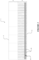
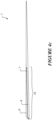
- the module 1 preferably comprises an underlapping region 2 extending from a head edge 4 of the module and an exposed region 3 extending from a foot edge 5 of the module.
- the underlapping region 2 is adapted to be substantially covered by the exposed region of an adjacent or overlapping module when installed on a building surface, as shown in Figure 5 .
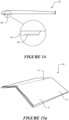
- the module may take a variety of forms, for example, several variations 1, 1a, 1b, 1c, 1d, 1e are shown in Figures 1 , 3 , 5 , 6 , 14 and 15 .
- the module preferably has at least one layer which is formed of an extruded material comprising one or more polymers and at least 40% filler and/or reinforcement.
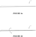
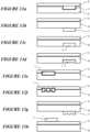
- Figure 4a shows a cross-sectional view of one embodiment of the module 1.
- the module comprises a single layer along a section of the module or along the entire length of the module.
- the layer is formed of an extruded material comprising at least about 40% w/w/ filler and/or reinforcement, more preferably at least about 60% w/w filler and/or reinforcement.
- At least a portion of the underlapping region 2 of the module is formed of the extruded material comprising at least about 40% w/w filler and/or reinforcement, more preferably at least about 60% w/w filler and/or reinforcement.
- the extruded material comprises one or more of the following polymers: polystyrene (GPPS), polyethylene terephthalate (PET), polyester methacrylate (PEM), high impact polystyrene (HIPS), acrylonitrile butadiene styrene (ABS), polyvinyl chloride (PVC), polyurethanes (PU), polyethylene (PE) including homopolymer, copolymer, block copolymer and terpolymer forms, polylactic acid (PLA), nylon (PA), acrylics (PMMA), high density polyethylene (HDPE), low density polyethylene (LDPE), linear low density polyethylene (LLDPE), medium density polyethylene (MDPE), cross linked polyethylene (PEX), thermoplastic elastomer (TPE), thermoplastic polyolefin (TPO), thermoplastic rubber (TPR), polypropylene (PP) including homopolymer and copolymer forms, polybutylene terephthalate (PBT), styrene-acrylonit
- suitable fillers include any one or more of talc, calcium carbonate, mica, silica, kaolin, calcium sulphate, magnesium hydroxide, stabilizers, dolomite, etc.
- suitable reinforcements include any one or more of glass fibres, glass beads, glass flakes, natural fibres such as flax, cellulose, wood fibres, wood flour, cotton and sawdust, inorganic fibres, polymer fibres, polymer scrim, polymer knit, polymer weave, aramids, ceramics, etc.
- Fillers are added to the extruded material to reduce the amount of the more expensive polymer component, hence reducing the material cost.
- increasing the filler content tends to negatively affect the physical properties of the extruded material.
- prior art injection moulded products typically require relatively low filler content, otherwise the material does not flow to fill the dies and/or becomes too hard to be mouldable and/or the moulded product is unstable (e.g., may be poor melt flow or may be due to thermal expansion) or brittle.
- Prior art products compensate by adding a reinforcing scrim layer between layers of polymer; however, these are typically difficult and expensive to manufacture.
- the extruded material of the present invention comprises at least about 40% w/w filler and/or reinforcement, and preferably at least about 60% w/w filler and/or reinforcement. In some embodiments, the percentage of filler and/or reinforcement is between about 60% and 95% by weight of the extruded material.
- Provision of filler and/or reinforcement into a layer can provide for an increased weight or density or bulk (e.g. volume) of a layer so formed and thereby of a module made by at least one of such a layer.
- the extruded material comprises both filler and reinforcement. That is at least 40% w/w of the extruded material comprises filler and reinforcement.
- the extruded material does not contain reinforcement.
- the extruded material comprises at least about 5% w/w reinforcement (i.e., in this embodiment, the extruded material comprises at least about 55% w/w filler and at least about 5% w/w reinforcement). In some embodiments, the extruded material comprises between about 5% and 20% w/w reinforcement, preferably about 10% reinforcement.
- the reinforcement comprises glass fibres.
- typical dimensions of the glass fibre prior to processing may be between about 0.5 and 5 mm in length (or may be about 1-5 mm, or about 2-5 mm, or about 3-5 mm in length) and about 0.015 to about 0.018 mm in diameter.
- the reinforcement may also reduce thermal expansion of the module, hence improving stability and durability of the module when exposed to cyclical variations in heat.
- the glass fibres align along the length of the module during the forming process. As a result, the module is particularly stable along its length (i.e., the longest dimension of the module, which typically undergoes greatest change in length due to thermal expansion).
- Table 1 compares the thermal expansion coefficient of three test samples: a) polymer (TPO) with no filler and no reinforcement, b) exemplary prior art product comprising a layer of reinforcing (polyester) scrim encapsulated between top and bottom TPO layers, the TPO layers comprising 40% w/w filler, and c) one embodiment of the present invention comprising polymer (TPO) with 80% w/w filler and 10% w/w reinforcement.
- heat was applied to the test sample to raise the temperature of the sample by about 80°C from ambient temperature. The dimensions of each sample were measured at initial (ambient) temperature of about 14°C and again at the final elevated temperature of about 94°C to determine the thermal expansion.
- the embodiment of the present invention demonstrates much less thermal expansion, compared to pure polymer.
- the present embodiment instead undergoes minimal thermal expansion that is comparable to polymer reinforced with a scrim layer, but does not suffer from the manufacturing challenges associated with the prior art product.
- Table 1 Thermal expansion coefficient of test samples with differing levels of filler. Polymer % filler % reinforcement Thermal expansion coefficient (10 -6 m/(m K)) TPO 0 0 165 TPO with reinforcing scrim 40 0 10 TPO 80 10 22
- the layer of the module is tough, heat-stable and low cost (in particular due to the high filler content).
- module is preferably manufactured in a single continuous forming process (described in more detail below). It is envisaged that module may be formed in lengths of at least about 0.5 m. Alternatively, the module may be formed in lengths of about 36 inches long. Alternatively, the module may be formed in lengths of at least about 1 m, 1,5 m, 2 m, 2.5 m, 3 m, or any numerical value in between.
- moulding the entire length of the module in a continuous process eliminates any weld lines. This increases the durability and weather resistance of the modules, and improves the appearance of the final product.
- the extruded material may further comprise one or more of the following additives: colorants (including but not limited to carbon black, titanium dioxide), flame retardants (including but not limited to magnesium hydroxide, aluminum trihydrate), stabilizers (including but not limited to UV light stabilizers such as hindered amine light stabilizers (HALS), and thermal stabilizers such as phenolics), foaming agents (including but not limited to exothermic, endothermic or gas foaming agents), lubricants, and/or biocides (including but not limited to particles of silver, including nano-sized silver particles).
- colorants including but not limited to carbon black, titanium dioxide
- flame retardants including but not limited to magnesium hydroxide, aluminum trihydrate
- stabilizers including but not limited to UV light stabilizers such as hindered amine light stabilizers (HALS), and thermal stabilizers such as phenolics
- foaming agents including but not limited to exothermic, endothermic or gas foaming agents
- lubricants including nano-sized silver particles.
- Figure 4b shows a cross-sectional view of a second embodiment of the module 1.
- the module comprises two layers along a section of the module or along the entire length of the module.
- the base or bottom layer 8 is formed of an extruded material comprising at least 60% filler and at least 5% reinforcement.
- the top layer 6 or both layers is/are formed of an extruded material comprising at least 60% filler and at least 5% reinforcement. That is, the percentages and/or material of the polymer(s) and/or filler and/or reinforcement may be the same or different in each layer.
- the material content of each layer is preferably selected to suit the function, appearance and/or exposure of the particular layer.
- Figure 4c shows a cross-sectional view of a third embodiment of the module 1.
- the module has at least one portion 10 which comprises at least three layers: a top layer 6, a bottom layer 8, and an intermediate layer 7 between the top and bottom layers.
- the module may be formed from more than three layers, for example if more than one layer of material forms a precursor to the top layer, intermediate layer and/or bottom layer.
- At least one layer is formed of an extruded material comprising at least 40% filler and/or reinforcement, preferably at least 60% filler and/or reinforcement.
- the module may further comprise one or more additional layers formed of material that may comprise less than 40% filler and/or reinforcement.
- the at least one layer formed of an extruded material comprising at least 40% filler and/or reinforcement is a base or bottom layer that substantially contributes to the structure of the module.
- this base or bottom layer is formed of an extruded material comprising at least 60% filler and at least 5% reinforcement.
- the base or bottom layer comprises about 80% to 85% w/w filler and/or reinforcement, more specifically, about 70% to 75% filler and about 10% w/w reinforcement.
- a base or bottom layer may have a thickness of about 1-3mm.
- the resulting layer(s) may provide resistance against significant thermal expansion of the module, which in turn may help reduce shear forces between layers and/or other structures attached to the module that may be due to thermal expansion of those other layers.
- the structural layer(s) may be provided as one or more intermediate and/or upper layer(s).
- the upper or top layer(s) 6 and/or the intermediate layer(s) 7 and/or two or more layers may also be formed of an extruded material comprising at least 60% filler and/or reinforcement.
- the extruded material comprises at least 5% reinforcement.
- the material of the matrix and/or filler and/or reinforcement may be the same or different in each layer.
- the top layer 6 may comprise at least 65% filler, and no reinforcement.
- the higher polymer content may be suitable for the top layer, e.g., to facilitate binding of colored material (as described in more detail below).
- a top layer may have a thickness of about 0.4mm.
- the intermediate layer may comprise about 100% polymer (i.e., the intermediate layer may not comprise filler or reinforcement), which may increase one or more particular reinforcing properties of the layer, such as waterproofing.
- the intermediate layer may comprise a polypropylene copolymer reinforced with a copolymer polyethylene.
- the reinforcing polymer may comprise up to about 50% w/w of the layer, preferably between 10% and 25% w/w of the layer.
- such an intermediate layer may have a thickness of about 0.5mm.
- a multi-layered module may be formed using at least the top layer, the intermediate layer and the base or bottom layer as described above.
- one or more of the layers may comprise(s) three-dimensional features such as surface texturing, surface relief or other three-dimensional pattern or ornamentation.
- Figure 1 schematically shows surface texturing on the exposed regions 3 of the module 1 (i.e., the surface is not smooth), to simulate asphalt shingles.
- At least a portion of the exposed region 3 of the module has three-dimensional surface features. Accordingly, in the multi-layered embodiments shown in Figure 4b , at least a portion of the upper surface of the top layer, corresponding to the exposed region in the finished module, may have three-dimensional surface features.
- the module may additionally or alternatively comprise two or three dimensional surface features such as coloring, patterning, surface cracking or fracturing or other two- or three-dimensional decoration or ornamentation.
- These three dimensional and/or two dimensional (e.g. flat) surface features are preferably provided on at least the exposed region 3 of the module, in order to simulate another type of natural or manufactured material, including but not limited to asphalt shingles, slate, timber shingles or shakes, concrete tiles, stone chips, weatherboard, thatch, stone, woodgrain, metal (e.g., copper tiles), etc.
- the module comprises at least three layers at the exposed and fastening regions.
- the top layer 6 provides the cosmetic finish on the exposed region of the module, and preferably includes surface features on the top surface as described above.
- the intermediate layer 7 may provide additional reinforcement, water or weather resistance and/or a binding layer between the top and bottom layers.
- the bottom layer 8 forms the base structure of the module and therefore preferably extends throughout the entire width and length of the module.
- the bottom surface of the bottom layer at the exposed region further includes projections (e.g., ribs) that provide adhesion surfaces, as described in more detail below.
- the module may comprise three layers in any arrangement, and across any region of the module. Exemplary embodiments are shown in Figures 13a-13h .
- the module comprises at least two layers at the exposed and/or fastening region(s).
- the top layer 6 may provide the cosmetic finish on the exposed region of the module, and preferably includes surface features on the top surface as described above.
- the base or bottom layer 8 may provide the base structure for the module, and may be reinforced.
- the bottom surface of the base layer 8 may further includes projections (e.g., ribs) that provide adhesion surfaces, as described in more detail below.
- the layer may have a cosmetic finish (e.g. surface color added) on the exposed region of the module, and preferably includes surface features on the top surface as described above.
- the layer may also provide structural support for the module, and may likewise be reinforced (e.g., with reinforcement additives, surface treatment, surface features such as projections, etc.).
- one or more of the layers may be extruded. If two or more layers are extruded, they may be co-extruded.
- the layers may be extruded in series from two or more serially arranged extruders 20a, 20b, 20c, as shown in Figure 9 .
- a first extruded layer is deposited onto an advancing support surface of a continuous forming machine 11, and subsequently the other extruded layer(s) is/are deposited on top of the first layer.
- the layers then proceed as a layered feed to be molded between the first forming surface 12 and second forming surface 13, preferably as described below.
- one or more of the layers may be molded by thermoforming, compression moulding, pressing or other method of forming.
- the layers are subsequently joined together preferably by the continuous forming machine 11 as described below.
- the layers are joined or laminated together to form the module in a continuous forming process (described in more detail below).
- the layers and/or their content, such as the polymer(s) is/are selected to be compatible with each other, to ensure adequate joining/fusing between each layer.
- the preferred forming process allows for multiple layers in various configurations (e.g., varying continuity, material properties, etc) to be joined together to form the finished module. Referring to the cross-sectional view of one example of the module shown in Figure 4c , in a preferred embodiment of the present invention, one or more properties of the intermediate layer 7 varies along the length and/or width of this layer.
- the thickness of the intermediate layer 7 varies along its width. Specifically, the intermediate layer is thinner near the foot edge 5 of the module, and increases in thickness towards the middle of the module. As will be discussed in more detail below, this thicker portion preferably coincides with the fastening region of the module.
- the reinforcing layer 7 may be formed above or below the top or bottom layer of the module respectively.
- the reinforcing layer may be present intermediate the head edge 4 and foot edge 5 of the module, or may extend to one or both of the edges.
- the intermediate layer (where present) may be between 0.01 and 10 mm thick, whether of a constant thickness throughout, or whether the thickness varies as discussed above.
- the intermediate layer may be between 0.1 and 0.5 mm thick; or may be any numerical value between 0.01 and 10 mm.
- the top and bottom layers may each be between 0.1 and 50 mm thick, whether the thickness is constant or varying across each layer.
- the top layer is between 0.1 to about 10 mm thick.
- the top layer is about 0.05, 0.1, 0.2, 0.3, 0.4, 0.5, 0.6, 0.7, 0.8, 0.9 mm thick, or may be numerical values between each of these.
- the bottom layer is about 0.1 to about 10 mm thick.
- is the bottom layer about 0.5, 1, 2, 3, 4, 5, 6, 7, 8, 9 mm thick, or may be numerical values between each of these.
- the varying property of the intermediate layer could be a change in surface area of the intermediate layer, for example by corrugating (or changing the degree of corrugations on) a portion of the intermediate layer.
- Additional or alternative properties of the intermediate layer which may be varied along the length or width of the layer include tensile strength, shear strength, resilience, elasticity, flexibility, toughness, fire resistance, water resistance, continuity or uniformity, water-proofing, impact resistance, resistance to pull through, fixing capability, chemical resistance, puncture resistance, content of filler and/or reinforcement, concentration of filler and/or reinforcement, color, microbial resistance, temperature resistance, light/heat absorption/reflectivity, thermal transfer, etc., of the layer. Regarding continuity and uniformity, there may be areas where the intermediate layer is not present in the module, such that the intermediate layer is discontinuous across the length and/or width of the module.
- one or more property/properties of the other layers may additionally or alternatively vary along the length and/or width of the layer.
- the surface area of the intermediate layer may be varied by changing the properties of three-dimensional surface features on the intermediate layer.
- the intermediate layer may have three-dimensional surface texturing, or other projections, corrugations, reinforcements, chemical coatings, protrusions, apertures, perforations or surface roughness which increase the mechanical bonding of this layer to the top and/or bottom layers.
- any one of the layers may be pre-formed (e.g., by extrusion, or other type of forming process) and subsequently introduced to the forming/lamination process to form the module.
- the layer may be heated or reheated so that it is in a molten or pliable state when fed to the forming/laminating machine.
- the height or width of the surface features may vary along one or more directions of the layer, or in specific areas of the layer.
- the number of surface features i.e., the concentration of surface features per unit length or width of the layer
- the variation in the property/properties of the intermediate layer may be caused by deforming the intermediate layer before or during joining or laminating to the top and/or bottom layers. For example, by stretching a localized portion of the intermediate layer while it is still in a molten, semi-molten or pliable state, the concentration of surface features within this region may be reduced. Accordingly, the mechanical bond strength at this region would be weaker compared to other non-deformed regions, or preferentially reduced to provide for desired mechanical properties of the intermediate layer and its reinforcement of the associated upper and lower layers.
- the intermediate layer is a reinforcing layer (e.g., a reinforcing film, mesh, scrim, weave, fibre, fabric, wire, string, web or sheet) between the top and bottom layers.
- the intermediate reinforcing layer preferably provides for one or more of: resistance against shrinkage, resistance against warping, resistance against tearing, increased toughness, prevention against unwanted deflections of the module, weather or water resistance, reduced flammability, impact resistance, resistance to pull through (e.g., of fasteners due to high winds), fixing capability, chemical resistance, puncture resistance, sealing (e.g., self-sealing around fasteners), shape memory and increased resistance against delamination of the layers, adhesive/gluing/bonding capability, etc.
- the pull through strength of the module is preferably at least as required in the standard specification for asphalt shingles made from glass felt and surfaced with mineral granules (ASTM D3462).
- the standard specifies that when pulling a nail head through the shingle at 100mm/min, the pull through force is at least 90 N. Accordingly, the nail pull through force demonstrated by the present module is at least about 90 N, more preferably at least about 100 N, and may be more than 130 N.
- the intermediate layer may provide a substantially water or liquid resistant barrier, or a water or liquid impermeable barrier between the top and bottom layers. This is particularly advantageous where the top or bottom layers are porous.
- the top layer of the module may be fractured or otherwise crazed to provide surface ornamentation for simulating another type of material.
- the intermediate layer preferably provides a substantially waterproof barrier below this top surface, at least at the porous region(s).
- the reinforcing properties of the intermediate layer may vary depending on the requirements at different sections of the module. At zones of increased exposure or under increased loading, for example, the reinforcing properties of the intermediate layer may be increased, but at other sections, may be reduced to reduce the amount of material used.
- the module may further comprise a fastening region 14 for receiving one or more fasteners that fix the module to the building surface when installed.
- the fastening region may be substantially adjacent the exposed region 3 and within the underlapping region 2.
- the fastening region may include a visual guide or boundary markers to allow visual identification of the region.
- the fasteners may be nails, screws, etc, which puncture or penetrate the module when installed.
- the intermediate layer may extend from at or adjacent the foot edge 5 of the module to within or beyond the fastening region 14 of the module.
- the intermediate layer may be present only along the fastening region 14 of the module.
- the intermediate layer may extend from at or adjacent the foot edge, to at or adjacent the underlapping region of the module. That is, the intermediate layer may provide for additional reinforcement and/or weather resistance throughout the exposed region of the module.
- the module may comprise more than one intermediate layer.
- the two or more intermediate layers may comprise the same or different material and/or may perform the same or different functions.
- the layers may be present as discrete intermediate layers in different regions of the module or there may be multiple intermediate layers in one or more regions of the module. For example, there may be two intermediate layers in the fastening region, one providing a waterproofing function, the other providing self-sealing properties around fasteners.
- the reinforcing property/properties of the intermediate layer may be optimized preferentially within this fastening region 14, to increase the toughness and tear-resistance of the module at this layer. Additionally, the reinforcing property/properties of the intermediate layer may also be increased within the exposed region of the module.
- the intermediate layer may be thicker along the fastening region, compared to within the exposed region.
- the intermediate layer may comprise thickened regions or other 3-dimensional qualities within the fastening region 14, which provide for a fastening region capable of retaining a fastener penetrating the fastening region or resisting tear or pull through of the module by shear force applied to the module or each of the said layers by the fastener.
- the reinforcing property/properties of the intermediate layer may be optimized preferentially along the direction of the length of the module and/or along the direction of the width of the module. It will be appreciated that the direction and/or regions of optimizing or increasing the reinforcing properties of the intermediate layer will depend on the structural requirements (e.g., the amount of loading, shear force, tensile force, strain, etc., along that direction or within that region) of the module when installed.
- variations in these properties may be achieved when forming the intermediate layer, whether by extrusion or other forming processes. These variations may additionally or alternatively be achieved by deforming (e.g., stretching) the intermediate layer when it is being joined to the top and/or bottom layers, and is in a molten or semi-molten moldable state.
- the intermediate layer when being joined to the top and/or bottom layers, is preferably in a molten or semi-molten state, or a cold but pliable, formable or moldable condition. In this state, the intermediate layer is able to be deformed with little or no localized areas of high stress.
- the intermediate layer may form chemical bonds with compatible material(s) in the top and/or bottom layer.
- the intermediate layer may be inserted between molten or semi-molten top and bottom layers, and may therefore form chemical bonds with these layers.
- the module may be shaped and/or contoured during the joining/laminating process, while the intermediate layer is in the cold but pliable or molten or semi-molten moldable state. This ensures that the intermediate layer remains substantially aligned and/or substantially consistently positioned between the top and bottom layers through the shape and/or contour. This is shown in the detailed views of Figures 7 and 8 .
- the module may be shaped and/or contoured via a casting, thermoforming, pressing or other forming process, whether continuous or discontinuous, during or after the joining/laminating process.
- all three layers of the module are in a molten, semi-molten, cold but pliable, formable or moldable condition when being joined together. This may further increase the strength of the chemical bond between compatible materials in each layer. This may additionally reduce the occurrence of localized high stress points in the module, whether or not the module is further shaped after joining the layers.
- the material for each of the layers is preferably chosen to have a melt flow index and/or heat capacity sufficiently high such that the layer(s) remain molten or semi-molten or pliable while the module is formed.
- the layers are processed at a sufficiently high temperature such that the layers remain molten or semi-molten or pliable while the module is formed.
- the layers are each made of, or comprise, one or more polymer(s).
- Materials which may be used include (but are not limited to) general purpose polystyrene (GPPS), polyethylene terephthalate (PET), polyester methacrylate (PEM), high impact polystyrene (HIPS), acrylonitrile butadiene styrene (ABS), polyvinyl chloride (PVC), polyurethanes (PU), polyethylene (PE) including homopolymer, copolymer, block copolymer and terpolymer forms, polylactic acid (PLA), nylon (PA), acrylics (PMMA), high density polyethylene (HDPE), low density polyethylene (LDPE), linear low density polyethylene (LLDPE), medium density polyethylene (MDPE), cross linked polyethylene (PEX), thermoplastic elastomer (TPE), thermoplastic polyolefin (TPO), thermoplastic rubber (TPR), polypropylene (PP) including homopolymer and copolymer forms, Polybuty
- any one or more of the layers may further comprise one or more additives, such as, but not limited to fillers (including but not limited to talc, calcium carbonate, mica, silica, kaolin, calcium sulphate, magnesium hydroxide, stabilizers, dolomite), colorants (including but not limited to carbon black, titanium dioxide), reinforcements (including but not limited to glass fibres, glass beads, glass flakes, natural fibres such as flax, cellulose, wood fibres, wood flour, cotton, sawdust, and inorganic or polymer fibres, scrim, knits, weave, non-woven, aramids, ceramics), flame retardants (including but not limited to magnesium hydroxide, aluminum trihydrate), stabilizers (including but not limited to UV light stabilizers such as hindered amine light stabilizers (HALS), and thermal stabilizers such as phenolics), foaming agents (including but not limited to exothermic, endothermic or gas foaming agents), lubricants, or biocides (including but not limited to particles of
- the top layer preferably has a high UV resistance.
- the module is preferably configured and materials preferably chosen to withstand cyclical variations in temperature, for example, about -40 to about 100 degrees Celsius.
- the polymer(s) of the top and bottom layers has/have a lower degree of crystallinity compared to the polymer(s) of the intermediate layer. That is, the intermediate layer comprises a tougher, more crystalline polymer or polymer blend compared to the top and bottom layers.
- the top and bottom layers may comprise an amorphous polymer or a polymer which is less crystalline compared to the intermediate layer.
- the intermediate layer may comprise polypropylene (PP).
- the top and/or bottom layers may comprise thermoplastic polyolefin (TPO), which is less crystalline or has fewer crystalline regions compared to polypropylene (PP).
- TPO thermoplastic polyolefin
- the layers may each have any degree of crystallinity compared to each other.
- the relative crystallinity of the layers may be achieved during manufacture of each layer, for example by controlling the temperature, rate of cooling, rate of extrusion, shear forces, or other factors as known in the art.
- the top and bottom layers may substantially thermally insulate or encapsulate the intermediate layer, so that the intermediate layer remains molten or semi-molten or pliable during the forming process. This controls the amount and/or rate of shrinkage of the crystalline or semi-crystalline intermediate layer throughout the cooling process, reducing warping in the module.
- the top and bottom layers may also substantially transfer or provide heat to the intermediate layer, to promote or maintain its molten or semi-molten or pliable state.
- the intermediate layer may also provide a binder layer for binding materials in the top and/or bottom layer together to form the module.
- the top layer may comprise sections of non-homogenous and/or non-compatible materials in order to achieve a particular surface texture or appearance simulating another type of material.
- the intermediate layer may be chosen to comprise a material which is compatible with each of the materials in the top layer. The intermediate layer therefore binds to each of the discontinuous sections of the top layer, effectively acting as a binder for binding these sections together.
- the module need not comprise three layers throughout the entire unit of module.
- the module may comprise a single layer or double layers throughout, or at specific regions, as described previously.
- the top and/or bottom layer may be foamed. This additionally reduces the weight of the module.
- the bottom layer 8 is made of a foamed polymer, such as foamed thermoplastic polyolefin (TPO).
- the module may comprise one or more anti-scuff or protective layers on a top surface of the module, to protect at least the exposed region of the module during storage, transport and installation.
- the layer may be applied as an integral layer, or may be removably provided as a release sheet (to be removed after installation).
- the anti-scuff layer may be a layer of substantially virgin polymer, or a layer or coating comprising polymer or other suitable materials.
- the module may comprise one or more side laps for lapping under an adjacent module, to increase water resistance between adjacent modules.
- the side lap may be thinner, and/or may comprise fewer layers than other portions of the module. Side laps can provide for regions upon which adjacent modules may overlap with another module.
- the under surface of the layer may comprise projections instead of being a solid, continuous surface.
- the projections provide surfaces upon which the exposed region of the module may be adhered to the top surface of the underlapping region of an adjacent and/or overlapping module when installed.
- the projections provide sufficient adhesive surface area over discrete regions of the base, instead of a solid continuous surface, which would be more affected by shrinkage or thermal expansion/contraction, causing issues with adhesion.
- the projections further provide the required strength and rigidity of the layer, while reducing the weight of the layer.
- the projections comprise one or more longitudinal ribs 15 or other formations extending along the length of the module.
- Each longitudinal rib 15 may be continuous or discontinuous throughout its length, but preferably provides sufficient coverage of the module to provide sufficient adhesion surfaces. More preferably, the longitudinal rib extends through the entire length of the module, in order to provide sufficient strength along the length, and prevent warping along the length.
- the longitudinal ribs 15 extend substantially parallel to the foot edge 5 of the module.
- the longitudinal rib 15 may extend along a direction which is not parallel to the foot edge (e.g., the rib(s) may extend(s) diagonally across the module), but the rib preferably still extends along a substantial portion of the length of the module.
- the ribs are positioned near the foot edge 5 of the module, so that this edge of the exposed region of the module be adhered to the top of the adjacent or overlapping module, and may sit flush on the top surface.
- the module may also be formed with a convex precamber perpendicular to the length of the module, such that the exposed region is curved downwardly of the underlapping region.
- This pre-load pressure encourages the projections/ribs to contact firmly onto the underlapping panel when installed on the building surface.
- each longitudinal rib 15 there are a plurality of longitudinal ribs 15 (e.g., three ribs), extending substantially parallel to each other and spaced approximately 1 to 100 mm (preferably 1 to 10 mm) apart from each other.
- the height of the, or each, longitudinal rib may be between 1 and 100 mm (preferably, between 1 and 10 mm).
- the or each longitudinal rib may be between 1 and 1000 mm wide (preferably between 1 and 10 mm wide, or sufficiently wide to provide surfaces for adhering the module to the top of an adjacent or overlapping module when installed.
- the under surface of the bottom layer may further comprise a plurality of transverse ribs 16.
- These transverse ribs 16 may extend substantially perpendicular to the longitudinal ribs 15 and/or perpendicular to the length of the module.
- the transverse ribs may extend along any other direction, but preferably still extends along a substantial portion of the width of at least the exposed region of the module.
- transverse ribs may provide adhesion surfaces in addition to, or alternatively to the longitudinal ribs.
- the transverse ribs preferably strengthen at least the exposed region of the module, preventing warping or curling of the module along its width.
- the transverse ribs 16 therefore preferably extends from at, or adjacent, the foot edge 5 to at, or adjacent, the underlapping region of the module.
- the transverse ribs are spaced between 1 and 100 mm (preferably, 1 and 10 mm) apart from each other and extend substantially parallel to each other.
- the width of each transverse rib may be between 1 and 1000 mm (preferably, between 1 and 10 mm).
- the height of the transverse ribs tapers from at or adjacent the foot edge to, at, or adjacent, the underlapping region. This means that there is a decrease in spacing between the module and the building surface from the exposed region towards the underlapping region. This enables at least the exposed region of the adjacent overlapping module to be kept substantially parallel to the building surface.
- the projections are preferably molded into the under surface of the exposed region of the module during the forming process, for example by one or more die faces on the second forming surface 13.
- the projections may be pre-formed or post-formed from the same material as the under surface of the module and incorporated into the module during or after the forming process.
- the projections may be formed from a different material compared to the under surface of the module, and may be incorporated into the module before, during or after forming the module.
- the projections may further comprise surface features 19, such as surface roughness, on one or more surfaces, preferably a bottom surface.
- the features increase the surface area of the surface, to increase the peel strength and/or bond strength of the projection to the upper surface of the underlapping tile, to which the projection is adhered to.
- Examples of surface features include corrugations, serrations, projections, ribs, nodes, surface roughness, etc.
- the shape and configuration of the ribs may be selected to provide different attachment properties at different regions of the rib, e.g., a planar, bottom surface of the rib may provide different resistance against shear and/or peel compared to lateral faces of the rib.
- Other surfaces of the module may also or alternatively comprise surface features to increase the bond strength between adhered surfaces.
- the top surface of the underlapping region of the module may comprise surface features to increase the peel and/or bond strength between the top surface and the under surface of the overlapping module.
- the module may further comprise one or more continuous or discontinuous strips of adhesive 25 on the top surface of the underlapping region of the module (optionally which may be exposed upon removal of a release sheet), configured to contact the projections on the under surface of the exposed region of an adjacent or overlapping module when installed.
- adhesive may be provided on a bottom surface of the module (e.g., the bottom surface of the projections, if provided) to be adhered to a top surface of an underlapping module during installation.
- the release sheet 26 may be integrally molded or otherwise formed with or incorporated into the module. Prior to installation, the release sheet 26 may contact the adhesive region 25 of an adjacent module. During installation, the two modules may be separated to expose the adhesive on one module, and the release sheet can remain on the other module. In this way, the modules may be provided and/or transported in stacks of two or more modules.
- adhesive may be applied to the projections/ribs and/or to the top of the underlapping region of the module on-site.
- the module comprises a plurality of formed surfaces 9, wherein each of the formed surfaces comprises three-dimensional surface features, as shown in Figure 1 .
- each formed surface is a molded segment along the length of the module. For reference, we have defined the length of the foot edge 5 as the length of the module, and the distance between the foot edge 5 and the head edge 4 as the width of the module.
- Each formed surface 9 may resemble an individual tile, shingle, slate or shake. Alternatively, each formed surface may resemble a set of tiles, shingles, slates or shakes.
- Each formed surface 9 comprises an underlapping region 2 and an exposed region 3, wherein the underlapping region is adapted to be substantially covered by the exposed region of an adjacent or overlapping module when installed on a building surface.
- the module 1 may therefore be installed with the row of formed surfaces 9 simulating a row of tiles, shingles, slates, shakes, etc.
- the module may be subsequently sectioned (or divided or partitioned) to provide a plurality of smaller module sections for installation onto the building surface.
- the smaller module sections may each contain a single formed surface 9 simulating an individual tile, shingle, slate, shake, etc.
- the smaller module sections may resemble a set of tiles, shingles, slates or shakes. Examples of these smaller module sections are shown in Figures 3 and 6 .
- each smaller module section may contain a plurality of formed surfaces.
- each formed surface 9 is molded by an individual die or mold of a continuous forming machine. Where there are a plurality of formed surfaces 9 in the module, all the formed surfaces are preferably joined or laminated to each other without weld lines, attachments (such as gluing, etc) or injection molding points. Use of the term "joined" in this context is not intended to require that each of the formed surfaces were ever separated, i.e., the formed surfaces maybe integrally formed together in situ during the manufacturing/molding process.
- the preferred method of forming a module having a plurality of formed surfaces joined together without weld lines, attachments or injection molding points is described as follows, and with reference to Figure 9 .
- the continuous forming machine 11 is fed a feed material able to assume and retain a form after being molded between a first forming surface 12 and a second forming surface 13.
- At least the first forming surface 12 comprises a plurality of die faces 21 provided in sequence, configured to mold the three-dimensional surface features onto the module. That is, each formed surface 12 along the module is molded by one die face.
- the module may be molded upside down (i.e., the bottom surface is molded with the surface features, which when installed, becomes the top/exposed surface of the module).
- each die face is (at least slightly) different from the adjacent die face, in order to produce a module with formed surfaces 9 which appear (at least slightly) different from at least the adjacent formed surfaces.
- the module-clad surface may therefore more closely resemble a surface covered with individual asphalt shingles, slate, shingles, shakes, concrete tiles, stone chips, weatherboard, etc.
- the die faces may be the same as each other in order for formed surface 9 to be formed which are substantially identical or matching of each other.
- the number of die faces is offset from the number of formed surfaces in each module to be formed. That is, there are more or fewer die faces compared to the number of formed surfaces in each module.
- the number of die faces may match the number of surfaces to be formed on a module or along a length of a layer - thereby contributing to the matched or substantially identical nature of the formed surface (e.g. where copper tiles or tiles which are of matching resemblance are to be provided as a part of a module).
- each module has a series of formed surfaces which are arranged in a non-identical manner to the series of formed surfaces on at least the previously formed module and the next module to be formed. More preferably, each module has a series of formed surfaces which are arranged in a non-identical manner to the series of formed surfaces on a plurality of previously formed modules and a plurality of module to be subsequently formed.
- the module of Figure 1 which has seven formed surfaces 9, there are preferably at least eight die faces 21 along at least the first forming surface 12. The last die face therefore molds the first formed surface of the next module in this continuous forming process. Accordingly, this module and the next will have a different arrangement of formed surfaces.
- each module there may be fewer die faces 21 compared to the number of formed surfaces in each module to be formed. For example, if there is one less die face compared to formed surfaces, the first and last formed surfaces along a single module will be identical. Nevertheless, each module will have a different sequence of formed surfaces compared to the previously formed and subsequently formed modules.
- each formed surface preferably has three dimensional surface features which are different from the surface features of at least the adjacent formed surfaces. More preferably, the die faces are configured such that each of the formed surfaces within the module has three dimensional surface features which are different from the surface features of all other formed surface within the module.
- sequence of formed surfaces in each module may be further varied by swapping a die face with another die face along the first forming surface.
- each die face may be rotated in place to provide for a different orientation of three dimensional surface features on the formed surface to be molded, and hence a variation in the overall appearance of the formed surface.
- the die faces may be the same, so as to produce similar or identical formed surfaces.
- this embodiment may be used to produce modules which resemble ceramic tiles or metallic tiles such as copper tiles.
- the die faces may not mould three-dimensional surface features into the module, but may simply serve to divide the module into formed surfaces to resemble individual tiles.
- an alternative method may involve producing a long length of precursor which is subsequently sectioned to obtain multiple modules.
- the precursor will comprise multiple repeating sequences of formed surfaces.
- the precursor is not sectioned at the intersections where the sequences repeat.
- the precursor may have multiple repeating sequences of eight formed surfaces.
- the precursor is sectioned to obtain modules containing only seven formed surfaces. This sectioning may occur during or after the molding process.
- the important feature is that the number of die faces 21 provided in sequence on the first forming surface 12 is offset from the number of formed surfaces 9 in each module.
- the module may be post-treated once formed, for example by shaping, folding, coloring, corrugating, adding surface treatment(s) (e.g. biocides), perforating, laminating, coating, etc.
- surface treatment(s) e.g. biocides
- the module is shaped and/or cut and/or folded, once formed, to produce a ridge tile, a hip tile, a barge tile, an apex tile or other shaped/angled tiles, such as corrugated tiles.
- folded modules are shown in Figures 15a , 15b and 15c . It will be appreciated that the angle of the fold depends on the application.
- the region to be folded or shaped may be heated or re-heated in order to be bent or folded into shape after the module has been formed.
- the region to be folded or shaped 17 may comprise a reinforcing layer to increase the toughness and/or durability of this region.
- the folded/shaped modules may, be arranged in any suitable overlapping arrangement (over similar folded/shaped modules or other unfolded modules) for or when installing onto the building surface.
- precursor being the precursor to the final molded module.
- the precursor may therefore refer to a single layer, or to the layered precursor just prior to molding the layers together into the final product.
- a colored material is added to the one or more layers, before or while the layer is formed (whether by extrusion, injection molding or other forming methods as described above).
- the colored material is added onto the module after it has been formed/molded.
- the colored material may be added onto at least a portion of the top surface of a precursor. That is, the colored material is applied before and/or during the final molding process.
- the colored material may be one or more dyes or pigments or colored particles which may be used to add surface color and/or decoration and/or texture to the module.
- the colored material may be transparent, translucent or opaque, and may comprise multiple components of different types of coloring or colored agents.
- the colored material may be applied to a precursor or module that has already been colored during the forming process.
- Figure 10 One embodiment is shown in Figure 10 , in which the precursor is molded between a first forming surface 12 and a second forming surface 13.
- the colored material is applied at 30 to at least a portion of one of the forming surfaces. Subsequently, the colored material is transferred to the precursor during the molding step, when the precursor is formed between the first and second forming surfaces.
- the colored material may be sprayed or otherwise applied onto the first forming surface 12 and/or second forming surface 13.
- the specific gravity of the colored material is preferably greater than 1.
- the colored material may be applied directly or indirectly to the precursor and/or the forming surface by one or more of stamping, injecting, embossing, spraying, rolling, feeding, brushing, melting, immersing, dipping, sprinkling, depositing, by drawing or suctioning the colored material onto the precursor and/or forming surface using a vacuum system, etc.
- the first and/or second forming surface may comprise a printer head, etc., for depositing the colored material onto the precursor during the molding step.
- colored material may be applied (whether directly or indirectly) to a surface of a layer or layer precursor or a surface of a die face or a surface of the formed module, using a vacuum system.
- a colored material may be applied to a top surface of an upper layer to be used in forming a module, and a vacuum system may remove at least some of the applied colored material. The removal of the colored material may be removal from pre-defined areas of the surface upon which the colored material has been applied.
- the colored material is preferably applied to at least a portion of the die face(s) prior to the molding step.
- the colored material is therefore subsequently stamped, injected, embossed or otherwise applied onto or into a portion of formed surface(s) during the molding step.
- the application of colored material onto the different die faces may be consistent or different.
- the amount of colored material applied and/or the areas on which the colored material is applied may be different for each die face, in order to produce a module with color variations throughout the different formed surfaces, so that they more closely simulate individual tiles, shingles, etc.
- the colored material may comprise a plurality of components having different melt flow indices/viscosities, so as to produce a visual effect such as a tortoiseshell coloring effect.
- one or more components of the colored material may be a solid that does not melt (at least in the range of temperatures that the colored material undergoes), i.e., the component(s) may not have a melt flow index as such.
- the colored material is preferably applied to at least a portion of the upper surface of the top-most layer prior to, or during the step of joining or lamination of the layers to form the module.
- the precursor is extruded prior to molding, and the colored material is applied at 35 to a portion of the upper surface of the layer as the layer emerges from the extruder. This is schematically shown in Figure 11 .
- Figure 12 shows additional or alternative locations where the colored material may be applied.
- the colored material may be applied at 40, before a layer is extruded, or onto a layer which may be later formed with other extruded layers. Additionally or alternatively, the colored material may be applied at 50, after the module has been formed.
- the colored material preferably comprises a powder and/or a fluid capable of being dispersed upon at least the or a portion of the top surface of the exposed region, whether the application is direct or indirect to the surface, or whether a die face is used to convey the colored material to the surface.
- the colored material may be or may comprise charged particles.
- the charged particles may be configured to be attracted to the die face, or directly onto the precursor.
- the charged particles may be configured to be ejected from a source of such charged particles onto the precursor.
- the colored material may be or may comprise an adhesive for attaching the colored material to the precursor.
- the colored material may be applied through a stencil and/or a mask (not shown), to selectively color one or more portions of the top surface of the precursor. Accordingly, there may be more than one color application steps, in which the same or a different colored material may be applied through the same or a different stencil, or to another portion of the top surface of the precursor.
- Layering the application of colored material like this may produce variations in color or surface patterning which better emulate the simulated material.
Landscapes
- Engineering & Computer Science (AREA)
- Architecture (AREA)
- Civil Engineering (AREA)
- Structural Engineering (AREA)
- Mechanical Engineering (AREA)
- Laminated Bodies (AREA)
- Roof Covering Using Slabs Or Stiff Sheets (AREA)
- Life Sciences & Earth Sciences (AREA)
- Wood Science & Technology (AREA)
- Chemical & Material Sciences (AREA)
- Ceramic Engineering (AREA)
- Finishing Walls (AREA)
- Extrusion Moulding Of Plastics Or The Like (AREA)
Applications Claiming Priority (2)
| Application Number | Priority Date | Filing Date | Title |
|---|---|---|---|
| US201462085733P | 2014-12-01 | 2014-12-01 | |
| PCT/IB2015/059230 WO2016088026A1 (en) | 2014-12-01 | 2015-12-01 | A roofing, cladding or siding product |
Publications (3)
| Publication Number | Publication Date |
|---|---|
| EP3227506A1 EP3227506A1 (en) | 2017-10-11 |
| EP3227506A4 EP3227506A4 (en) | 2018-07-25 |
| EP3227506B1 true EP3227506B1 (en) | 2023-06-14 |
Family
ID=56091098
Family Applications (1)
| Application Number | Title | Priority Date | Filing Date |
|---|---|---|---|
| EP15866038.1A Active EP3227506B1 (en) | 2014-12-01 | 2015-12-01 | A roofing, cladding or siding product |
Country Status (7)
| Country | Link |
|---|---|
| US (1) | US10850440B2 (https=) |
| EP (1) | EP3227506B1 (https=) |
| JP (2) | JP7154760B2 (https=) |
| AU (1) | AU2015356690B2 (https=) |
| CA (1) | CA2969083C (https=) |
| NZ (1) | NZ770461A (https=) |
| WO (1) | WO2016088026A1 (https=) |
Families Citing this family (36)
| Publication number | Priority date | Publication date | Assignee | Title |
|---|---|---|---|---|
| CA2791532C (en) * | 2011-12-19 | 2015-04-14 | David Spencer | Shingle inserts and method for eliminating and preventing growth of algae, moss, or lichens on a roof |
| US20150240495A1 (en) | 2014-02-21 | 2015-08-27 | Owens Corning Intellectual Capital, Llc | Shingles with increased hydrophobicity |
| JP6820199B2 (ja) | 2014-03-07 | 2021-01-27 | ジニアテック リミテッド | 太陽熱制御システム |
| USD870322S1 (en) | 2017-10-19 | 2019-12-17 | Ludowici Roof Tile, Inc. | Tile |
| US10167639B2 (en) * | 2016-10-21 | 2019-01-01 | Ludowici Roof Tile, Inc. | Flush face wall tile |
| USD857245S1 (en) | 2017-10-19 | 2019-08-20 | Ludowici Roof Tile, Inc. | Tile |
| CA3053632A1 (en) | 2017-02-21 | 2018-08-30 | Zinniatek Limited | Substrate having decorated surface and method of production |
| WO2019016767A1 (en) | 2017-07-20 | 2019-01-24 | Zinniatek Limited | ROOF, PAREMENT OR CLADDING, OR ELEMENT FORMING ELEMENT OR HINGER FOR A ROOF |
| US11836807B2 (en) | 2017-12-02 | 2023-12-05 | Mighty Fire Breaker Llc | System, network and methods for estimating and recording quantities of carbon securely stored in class-A fire-protected wood-framed and mass-timber buildings on construction job-sites, and class-A fire-protected wood-framed and mass timber components in factory environments |
| US11395931B2 (en) | 2017-12-02 | 2022-07-26 | Mighty Fire Breaker Llc | Method of and system network for managing the application of fire and smoke inhibiting compositions on ground surfaces before the incidence of wild-fires, and also thereafter, upon smoldering ambers and ashes to reduce smoke and suppress fire re-ignition |
| US10814150B2 (en) | 2017-12-02 | 2020-10-27 | M-Fire Holdings Llc | Methods of and system networks for wireless management of GPS-tracked spraying systems deployed to spray property and ground surfaces with environmentally-clean wildfire inhibitor to protect and defend against wildfires |
| US11865390B2 (en) | 2017-12-03 | 2024-01-09 | Mighty Fire Breaker Llc | Environmentally-clean water-based fire inhibiting biochemical compositions, and methods of and apparatus for applying the same to protect property against wildfire |
| US12594448B2 (en) | 2019-06-22 | 2026-04-07 | Mighty Fire Breaker Llc | Environmentally-clean aqueous-based fire extinguishing biochemical liquid concentrates for mixing with proportioned quantities of water to produce fire extinguishing water streams |
| US10260232B1 (en) | 2017-12-02 | 2019-04-16 | M-Fire Supression, Inc. | Methods of designing and constructing Class-A fire-protected multi-story wood-framed buildings |
| US11865394B2 (en) | 2017-12-03 | 2024-01-09 | Mighty Fire Breaker Llc | Environmentally-clean biodegradable water-based concentrates for producing fire inhibiting and fire extinguishing liquids for fighting class A and class B fires |
| US20240157180A1 (en) | 2021-02-04 | 2024-05-16 | Mighty Fire Breaker Llc | Method of and kit for installing and operating a wildfire defense spraying system on a property parcel for proactively spraying environmentally-clean liquid fire inhibitor thereover to inhibit fire ignition and flame spread caused by wind-driven wildfire embers |
| US10653904B2 (en) | 2017-12-02 | 2020-05-19 | M-Fire Holdings, Llc | Methods of suppressing wild fires raging across regions of land in the direction of prevailing winds by forming anti-fire (AF) chemical fire-breaking systems using environmentally clean anti-fire (AF) liquid spray applied using GPS-tracking techniques |
| MX2020006278A (es) | 2017-12-15 | 2020-09-14 | Owens Corning Intellectual Capital Llc | Material para techo de asfalto modificado con polimero. |
| US11826592B2 (en) | 2018-01-09 | 2023-11-28 | Mighty Fire Breaker Llc | Process of forming strategic chemical-type wildfire breaks on ground surfaces to proactively prevent fire ignition and flame spread, and reduce the production of smoke in the presence of a wild fire |
| CN108219234A (zh) * | 2018-02-07 | 2018-06-29 | 厦门力嘉诚防水工程有限公司 | 一种石墨烯tpo阻燃防水卷材 |
| USD896998S1 (en) * | 2018-05-24 | 2020-09-22 | Atlas Roofing Corporation | Roofing shingle |
| US10947729B2 (en) | 2018-05-24 | 2021-03-16 | Atlas Roofing Corporation | Roofing shingles and roofing method |
| KR102780818B1 (ko) | 2018-06-29 | 2025-03-12 | 오웬스 코닝 인텔렉츄얼 캐피탈 엘엘씨 | 이형제층을 포함하는 루핑 재료들 |
| US10865565B2 (en) | 2018-07-11 | 2020-12-15 | Owens Coming Intellectual Capital, LLC | Shingles with increased hydrophobicity |
| EP4038248A4 (en) | 2019-09-30 | 2024-02-07 | Bmic Llc | COMPOSITE MEMBRANE FOR CONSTRUCTION APPLICATIONS |
| CN110922908A (zh) * | 2019-11-20 | 2020-03-27 | 江苏凯伦建材股份有限公司 | 预铺高分子防水卷材 |
| US12065835B2 (en) | 2019-12-03 | 2024-08-20 | Owens Corning Intellectual Capital, Llc | Roofing materials including a layer of a parting agent |
| US11911643B2 (en) | 2021-02-04 | 2024-02-27 | Mighty Fire Breaker Llc | Environmentally-clean fire inhibiting and extinguishing compositions and products for sorbing flammable liquids while inhibiting ignition and extinguishing fire |
| US20240252866A1 (en) | 2020-03-01 | 2024-08-01 | Mighty Fire Breaker Llc | Liquid hydrocarbon sorbing article of manufacture for inhibiting fire ignition involving flammable liquid hydrocarbons, while absorbing the flammable liquid hydrocarbons when spilled on a body of water and/or land |
| US12395116B2 (en) * | 2020-08-24 | 2025-08-19 | Colin Felton | Labor saving solar roofing shingle |
| CN112060722B (zh) * | 2020-09-29 | 2025-04-08 | 安徽宝翔建设集团有限责任公司 | 一种抗变形锁水型压花工地用布 |
| US11332937B1 (en) * | 2020-10-23 | 2022-05-17 | Bmic Llc | Roofing membrane with protrusions |
| CA3139154A1 (en) * | 2020-11-13 | 2022-05-13 | Certainteed Llc | Flat siding panel and panel siding system |
| EP4202148A1 (en) | 2021-12-22 | 2023-06-28 | Zinniatek Limited | Moulded article with decorative surface |
| EP4676736A1 (en) | 2023-03-10 | 2026-01-14 | Owens Corning Intellectual Capital, LLC | Composite board with edge reinforcement for improved mechanical performance |
| GB2700096A (en) * | 2023-12-15 | 2025-09-24 | Autex Industries Ltd | Fixing of pet panels to allow for recycling |
Citations (1)
| Publication number | Priority date | Publication date | Assignee | Title |
|---|---|---|---|---|
| US20110214372A1 (en) * | 2010-03-08 | 2011-09-08 | William Mullet | Insulated siding apparatus |
Family Cites Families (210)
| Publication number | Priority date | Publication date | Assignee | Title |
|---|---|---|---|---|
| US510027A (en) | 1893-12-05 | Corn-popper | ||
| DE46673C (de) | G. H. O. BÖKLEN in Stuttgart | Dachplatte mit verschiebbaren Befestigungsklammern | ||
| US1004338A (en) | 1911-08-07 | 1911-09-26 | Nelson A Austin | Molded shingle. |
| US1266137A (en) | 1916-06-26 | 1918-05-14 | Meldetile Corp | Roofing-tile. |
| US1634126A (en) | 1924-12-04 | 1927-06-28 | F L Tyra | Shingle |
| US1678333A (en) | 1926-06-09 | 1928-07-24 | Corroll C Figge | Roof and shingle securing means |
| US1741515A (en) | 1928-08-28 | 1929-12-31 | Halprin Martin | Shingle |
| US1941216A (en) | 1930-10-13 | 1933-12-26 | John C Mckeown | Outside covering for buildings |
| US2149818A (en) | 1937-10-01 | 1939-03-07 | William B North | Building construction |
| US2260446A (en) | 1940-05-24 | 1941-10-28 | Jr Ernest S Fooks | Shingle fastening device |
| US2362236A (en) | 1943-02-13 | 1944-11-07 | Edward F Bassler | Molded shingle |
| US2680565A (en) | 1945-12-03 | 1954-06-08 | Univ Colorado | Solar heating apparatus and method |
| US2568603A (en) | 1948-10-01 | 1951-09-18 | John B Anthony | Roofing and siding |
| US2756699A (en) | 1950-03-31 | 1956-07-31 | Lloyd K Lockwood | Roofing shingles and fasteners |
| US2624298A (en) | 1951-09-04 | 1953-01-06 | Farren Roy | Tile roof structure |
| US2766861A (en) | 1952-06-05 | 1956-10-16 | Abramson Harry | Building wall sidings |
| US3058265A (en) | 1962-03-09 | 1962-10-16 | Lapsensohn Jacob | Roofing shingle and shingle assembly |
| US3332830A (en) * | 1963-04-29 | 1967-07-25 | Owens Corning Fiberglass Corp | Asphaltic weathering sheet including continuous glass fibers |
| US3223018A (en) | 1963-11-05 | 1965-12-14 | Tucker Radina | Building structure with air circulation means |
| US3357064A (en) | 1966-02-23 | 1967-12-12 | Bishop & Babcock Corp | Molding clip |
| DE2002738C2 (de) | 1970-01-22 | 1983-11-03 | Manfred 4972 Löhne Mühle | Befestigung von Bekleidungselementen |
| US3661410A (en) | 1970-07-07 | 1972-05-09 | Keystone Consolidated Ind Inc | Panel latching mechanism |
| DE2145868C3 (de) | 1971-09-14 | 1979-01-04 | Hazemag Dr. E. Andreas Gmbh & Co, 4400 Muenster | Rotor für von heißen Trocknungsgasen durchströmte Prallmühlen |
| US4173243A (en) | 1975-10-17 | 1979-11-06 | Dunlop Limited | Safety tire and wheel rim assembly |
| US4173253A (en) | 1977-01-17 | 1979-11-06 | Solar Energy Research Corp. | Solar radiation collector and water cooler |
| US4201196A (en) | 1977-05-11 | 1980-05-06 | Zani David A | Solar energy air heating device |
| US4141182A (en) | 1978-02-02 | 1979-02-27 | Mcmullen John R | Corrosion proof snow guard |
| JPS5849669B2 (ja) | 1978-03-15 | 1983-11-05 | 松下電工株式会社 | 屋根材 |
| US4288959A (en) * | 1979-05-21 | 1981-09-15 | Murdock John B | Roofing or siding article |
| US4319437A (en) | 1980-01-24 | 1982-03-16 | Murphy John A | Roofing shingle assembly having solar capabilities |
| US4281639A (en) | 1980-01-31 | 1981-08-04 | Kuronen Seppo K | Solar heating system |
| US4411117A (en) | 1981-05-20 | 1983-10-25 | Bolha David J | Building siding replacement device and method |
| US4426823A (en) | 1981-06-02 | 1984-01-24 | Kobe Thomas R | Apparatus and method for mounting roofing tile |
| DE3320744A1 (de) | 1983-06-09 | 1984-12-13 | Wolfgang Dipl.-Chem. Dr. 6800 Mannheim Blaicher | Dachziegel |
| JPS6060652A (ja) | 1983-09-14 | 1985-04-08 | Canon Inc | 電子写真用光導電部材 |
| JPS6193750A (ja) | 1984-10-13 | 1986-05-12 | Fanuc Ltd | フアクトリ−・オ−トメイシヨン・システム |
| JPS61169562A (ja) | 1985-01-22 | 1986-07-31 | 積水化学工業株式会社 | 屋根 |
| US4956140A (en) | 1985-12-09 | 1990-09-11 | Aluminum Company Of America Alcoa Laboratories | Methods of and apparatus for producing biaxially oriented polymer product |
| JPS6365240A (ja) | 1986-09-05 | 1988-03-23 | Toshiba Corp | 空調装置 |
| GB2199860B (en) | 1986-11-05 | 1991-07-17 | Glidevale Building Prod | Roof ventilation tile |
| US4712351A (en) | 1986-11-10 | 1987-12-15 | The Celotex Corporation | Vinyl siding |
| US5053180A (en) | 1986-11-24 | 1991-10-01 | Aluminum Company Of America | Process for deformation of amorphous polymers |
| JPS63165633A (ja) | 1986-12-26 | 1988-07-08 | 株式会社オ−エム研究所 | ソ−ラ−システムハウス |
| JP2522289B2 (ja) * | 1987-02-27 | 1996-08-07 | 松下電工株式会社 | 平板屋根材及びその製造法 |
| US5070671A (en) | 1988-01-18 | 1991-12-10 | Oldcastle, Inc. | Roof tiles |
| US5104770A (en) | 1988-03-11 | 1992-04-14 | Hoechst Celanese Corporation | Positive-working photoresist compositions |
| US5094058A (en) * | 1988-04-01 | 1992-03-10 | Slocum Donald H | Roofing shingle |
| US4886554A (en) | 1988-09-29 | 1989-12-12 | Gaf Corporation | Solar roofing assembly |
| JPH0386928U (https=) * | 1989-12-25 | 1991-09-03 | ||
| US5076037A (en) | 1990-03-02 | 1991-12-31 | Nailite International | Decorative wall cover and method of installation |
| US5100274A (en) | 1990-10-29 | 1992-03-31 | Illinois Tool Works Inc. | Roofing fastener and improved screw therefor |
| JP2597243B2 (ja) | 1991-03-18 | 1997-04-02 | 株式会社オーエム研究所 | ソーラーシステムハウスの融雪方法 |
| JPH04325239A (ja) * | 1991-04-24 | 1992-11-13 | Asahi Chem Ind Co Ltd | 難燃性樹脂積層板 |
| JPH0534623A (ja) | 1991-07-30 | 1993-02-12 | Canon Inc | 走査光学装置 |
| US5630305A (en) * | 1991-08-26 | 1997-05-20 | Hlasnicek; Richard S. | Surface covering unit methods of use and manufacture |
| GB9209397D0 (en) | 1992-04-30 | 1992-06-17 | Attley Begonia | A fabricated roof tile |
| DE4216171A1 (de) | 1992-05-15 | 1993-01-14 | Walter Loidl | Energieschindel 2 |
| US5347785A (en) * | 1992-06-15 | 1994-09-20 | Certainteed Corporation | Two element shingle |
| US5295339A (en) * | 1992-08-10 | 1994-03-22 | Manner Value Plastic, Inc. | Simulated individual self-venting overlapping plastic shake |
| JP2940745B2 (ja) | 1992-09-30 | 1999-08-25 | 三洋電機株式会社 | パネル結合装置 |
| JPH0632527U (ja) * | 1992-10-01 | 1994-04-28 | 積水化学工業株式会社 | 屋根材 |
| JPH083244B2 (ja) | 1993-01-14 | 1996-01-17 | 元旦ビューティ工業株式会社 | 縦葺き屋根構造 |
| JP2604323Y2 (ja) * | 1993-03-18 | 2000-05-08 | 株式会社アスク | 屋根材 |
| JPH0724960A (ja) * | 1993-07-13 | 1995-01-27 | Toyo Tire & Rubber Co Ltd | 短繊維入り混入ゴムの繊維配向性製品の製造方法 |
| US5437735A (en) | 1993-12-30 | 1995-08-01 | United Solar Systems Corporation | Photovoltaic shingle system |
| JPH07217011A (ja) | 1994-01-26 | 1995-08-15 | Sanso:Kk | 高気密、高断熱住宅の冷暖房システム |
| JPH07218002A (ja) | 1994-01-31 | 1995-08-18 | Yuichi Yanagi | ソーラーシステム及びそれを備えた建物 |
| US5487247A (en) | 1994-06-11 | 1996-01-30 | Pigg; Willard L. | Ventilated roof and wall structure |
| US5475963A (en) | 1994-07-22 | 1995-12-19 | Chelednik; Robert | Method and device for repairing vinyl siding |
| US5690876A (en) * | 1994-07-25 | 1997-11-25 | Gallo, Jr.; Francis Anthony | System for continuous production of roofing shakes |
| US5651226A (en) | 1995-02-10 | 1997-07-29 | Archibald; John P. | Tile with solar energy collection capability |
| US5615523A (en) * | 1995-04-24 | 1997-04-01 | Owens-Corning Fiberglas Technology, Inc. | Roof having resinous shingles |
| EP0823011B1 (en) * | 1995-04-24 | 2001-10-31 | Owens Corning | Shingle having ribs and cavity on its underside |
| JP3440424B2 (ja) | 1995-07-13 | 2003-08-25 | 清水建設株式会社 | 建築物 |
| JP3797685B2 (ja) | 1995-08-25 | 2006-07-19 | ミサワホーム株式会社 | 建物の暖房装置 |
| JPH0966566A (ja) * | 1995-08-31 | 1997-03-11 | Sekisui Chem Co Ltd | 繊維強化熱可塑性樹脂発泡体及びその製造方法 |
| JP2668665B2 (ja) | 1995-09-06 | 1997-10-27 | 株式会社オーエム研究所 | ソーラーシステムハウス |
| JPH09275644A (ja) | 1996-04-01 | 1997-10-21 | Omron Corp | 太陽電池モジュールおよびそれを用いた太陽光発電システム |
| US5711126A (en) * | 1996-05-13 | 1998-01-27 | Owens-Corning Fiberglass Technology, Inc. | Resinous angled shingles for roof ridge lines |
| US5902683A (en) * | 1996-08-30 | 1999-05-11 | General Electric Company | Construction shingle |
| JPH10325214A (ja) * | 1997-05-27 | 1998-12-08 | Kubota Corp | 屋根瓦 |
| EP1000206A1 (en) | 1997-06-12 | 2000-05-17 | Giuseppe Libralato | Self-ventilating protective and decorative covering for walls and roofs |
| JPH116231A (ja) | 1997-06-17 | 1999-01-12 | Asahi Chem Ind Co Ltd | スラブ構造 |
| US6061978A (en) | 1997-06-25 | 2000-05-16 | Powerlight Corporation | Vented cavity radiant barrier assembly and method |
| US6201179B1 (en) | 1997-10-03 | 2001-03-13 | Nick Dalacu | Array of photovoltaic modules for an integrated solar power collector system |
| JPH11136540A (ja) | 1997-10-27 | 1999-05-21 | Canon Inc | 画像処理装置、コンピュータ読み取り可能な記憶媒体及びデジタル撮影装置 |
| US7296989B2 (en) | 1998-05-22 | 2007-11-20 | Mtp, Inc. | Continuous production of plastic siding panels with separate shingle appearance |
| US6164034A (en) * | 1998-08-31 | 2000-12-26 | Poly Proximates, Inc. | Fiber-reinforced molded plastic roofing unit and method of making the same |
| AUPP663998A0 (en) | 1998-10-21 | 1998-11-12 | Smith, Lachlan Kerry Oliver | A roof and wall sheeting system |
| GB9827993D0 (en) | 1998-12-17 | 1999-02-10 | Phi Design Ltd | Ventilated roof tile |
| US6145264A (en) | 1999-02-01 | 2000-11-14 | Dallaire; Michel | Bracket for suspended ceiling tiles |
| GB9913705D0 (en) | 1999-06-14 | 1999-08-11 | Univ Southampton | Solar roofing tile |
| US6248271B1 (en) * | 1999-12-16 | 2001-06-19 | Owens Corning Fiberglas Technology, Inc. | Method of making an insert for use in a mold for molding roof covering products |
| US6220956B1 (en) | 2000-02-14 | 2001-04-24 | Jay T. Kilian | Soffit fan |
| CA2301420C (en) | 2000-03-16 | 2008-10-28 | Royal Ecoproducts Ltd. | Plastic roof tiles |
| JP3423917B2 (ja) | 2000-04-18 | 2003-07-07 | 一郎 大本 | 横葺き屋根板装置 |
| US7253076B1 (en) | 2000-06-08 | 2007-08-07 | Micron Technologies, Inc. | Methods for forming and integrated circuit structures containing ruthenium and tungsten containing layers |
| US6908295B2 (en) | 2000-06-16 | 2005-06-21 | Avery Dennison Corporation | Process and apparatus for embossing precise microstructures and embossing tool for making same |
| NZ507270A (en) | 2000-09-29 | 2003-04-29 | Andrew Leo Haynes | Flexible tile trim flashings |
| JP2002235955A (ja) | 2001-02-07 | 2002-08-23 | Om Kenkyusho:Kk | ソーラーシステムハウス |
| US6941706B2 (en) | 2001-05-10 | 2005-09-13 | Monier Lifetile Llc | Vented eaves closure |
| NL1018067C2 (nl) | 2001-05-14 | 2002-11-15 | Stichting Energie | Inrichting voor het genereren van fotovoltaïsche energie. |
| JP3654856B2 (ja) | 2001-08-07 | 2005-06-02 | 積水化学工業株式会社 | 太陽電池付き屋根材 |
| US20050072091A1 (en) | 2003-02-14 | 2005-04-07 | Morris Richard Joseph | Roof tile support arrangement |
| US20030096096A1 (en) | 2001-11-19 | 2003-05-22 | Jo Byeong H. | Plastic rail system reinforced with fiberglass thermoplastic composites |
| JP2003239505A (ja) | 2002-02-14 | 2003-08-27 | Asahi House Sangyo Kk | 外装建材 |
| US20030154667A1 (en) | 2002-02-20 | 2003-08-21 | Dinwoodie Thomas L. | Shingle system |
| US7481057B2 (en) | 2002-04-01 | 2009-01-27 | Niket Keshav Patwardhan | Low cost solar energy extraction |
| US8206807B2 (en) * | 2003-06-02 | 2012-06-26 | Certainteed Corporation | Synthetic roofing shingle or tile |
| US20050072092A1 (en) | 2003-10-01 | 2005-04-07 | Scott Williams | High profile composition shingles for roofs |
| US8567601B2 (en) * | 2004-01-14 | 2013-10-29 | Tamko Building Products, Inc. | Roofing product |
| US20120117908A1 (en) * | 2004-01-14 | 2012-05-17 | Travis Turek | Roofing product |
| US7520098B1 (en) | 2004-01-16 | 2009-04-21 | Davinci Roofscapes, Llc | Stepped tile shingle |
| US7678991B2 (en) | 2004-02-17 | 2010-03-16 | Elk Premium Building Products, Inc. | Rigid integrated photovoltaic roofing membrane and related methods of manufacturing same |
| US7101279B2 (en) | 2004-04-27 | 2006-09-05 | O'hagin Harry T | Solar-powered attic vent with a one-piece, fitted skeleton |
| US7225592B2 (en) | 2004-05-27 | 2007-06-05 | Davis Scott A | Siding clip |
| JP2006022481A (ja) | 2004-07-06 | 2006-01-26 | Mitsubishi Heavy Ind Ltd | ソーラ瓦、ソーラ瓦屋根、およびそれを用いた太陽熱温水設備 |
| US20060026908A1 (en) * | 2004-08-05 | 2006-02-09 | Gregori Werner K H | Simulated wood shingles with multiple alignment features |
| JP2006063271A (ja) | 2004-08-30 | 2006-03-09 | Hajime Kishi | 繊維強化エポキシ樹脂複合材料、及びその成形加工品 |
| US20060080942A1 (en) | 2004-10-15 | 2006-04-20 | O'neill Kevin M | Facing unit construction |
| JP2005191578A (ja) | 2004-11-29 | 2005-07-14 | Takamitsu Hayashida | 太陽光発電システム |
| WO2006063333A2 (en) | 2004-12-09 | 2006-06-15 | University Of Hawaii | Heat and mosture disipating building cladding |
| US7987650B2 (en) | 2008-10-08 | 2011-08-02 | Pollack Robert W | Device and method for repairing building surfaces |
| DE202005002105U1 (de) | 2005-01-05 | 2005-06-30 | Bayerische Dachziegelwerke Bogen Gmbh | Dachziegel |
| US7836654B2 (en) | 2005-08-05 | 2010-11-23 | Owens Corning Intellectual Capital, Llc | Shingle with reinforced nail zone and method of manufacturing |
| US8557366B2 (en) | 2005-08-05 | 2013-10-15 | Owens Corning Intellectual Capital, Llc | Roofing shingle including sheet as headlap |
| US20070078191A1 (en) | 2005-09-30 | 2007-04-05 | Guhde Brian J | Foamed reinforced composite siding product |
| US7441383B2 (en) | 2005-11-04 | 2008-10-28 | O'neal Jerry D | Fastener guide for siding |
| AU2006316231B2 (en) | 2005-11-16 | 2012-07-12 | Manufacturing Systems Limited | Improvements in or relating to forming apparatus |
| US20070119109A1 (en) | 2005-11-25 | 2007-05-31 | Peter Kuelker | Precast panel mounting system |
| CN101375111A (zh) | 2006-01-17 | 2009-02-25 | 索利安特能源公司 | 聚光式太阳能电池板及相关系统和方法 |
| US7509775B2 (en) | 2006-06-30 | 2009-03-31 | Lumeta, Inc. | Profile roof tile with integrated photovoltaic module |
| US7506477B2 (en) | 2006-06-30 | 2009-03-24 | Lumeta, Inc. | Profile roof tile with integrated photovoltaic module |
| JP4931116B2 (ja) | 2006-07-27 | 2012-05-16 | 日本電信電話株式会社 | 電気化学装置、および電気化学装置のための電極材料の製造方法 |
| US7735287B2 (en) | 2006-10-04 | 2010-06-15 | Novik, Inc. | Roofing panels and roofing system employing the same |
| US20080121270A1 (en) | 2006-11-28 | 2008-05-29 | General Electric Company | Photovoltaic roof tile system |
| CA2672180A1 (en) | 2006-12-11 | 2008-06-19 | To Ip Holding Company Pty Ltd. | Heating and cooling system |
| JP4485539B2 (ja) | 2007-01-23 | 2010-06-23 | オーエム計画株式会社 | ソーラーシステムハウス |
| US7735286B2 (en) | 2007-02-05 | 2010-06-15 | Exteria Building Products | Roof and wall covering with improved corner construction |
| US7726086B2 (en) * | 2007-02-05 | 2010-06-01 | Certainteed Corporation | Panel of roofing shingles |
| US20080271773A1 (en) | 2007-05-01 | 2008-11-06 | Jacobs Gregory F | Photovoltaic Devices and Photovoltaic Roofing Elements Including Granules, and Roofs Using Them |
| WO2008137966A2 (en) | 2007-05-07 | 2008-11-13 | Robert Stancel | Structures for low cost, reliable solar roofing |
| US20080302031A1 (en) | 2007-06-05 | 2008-12-11 | Solar Roofing Systems, Inc., | Integrated solar roofing tile connection system |
| WO2009000091A1 (de) | 2007-06-25 | 2008-12-31 | POSNANSKY, André | Dachaufbau für ein solarsystem |
| ITTV20070113A1 (it) | 2007-06-25 | 2008-12-26 | Soleya Srl | Pannello modulare per la copertura ventilata di tetti che integra un modulo intercambiabile a celle fotovoltaiche od uno scambiatore di calore, con moduli collegabili in serie in un sistema combinato di tetto |
| WO2009006213A2 (en) | 2007-06-28 | 2009-01-08 | Kalkanoglu Husnu M | Photovoltaic roofing tiles and methods for making them |
| JP2009127921A (ja) | 2007-11-22 | 2009-06-11 | Om Keikaku Kk | 採冷システム |
| EP2075389B1 (en) | 2007-11-30 | 2012-02-01 | Matthew Barnes | Roof section comprising solar thermal slates |
| US7713089B2 (en) | 2008-02-22 | 2010-05-11 | Redwood Renewable, Llc | Photovoltaic roofing tile with a plug and socket on 2 opposite edges |
| US20100037548A1 (en) * | 2008-08-18 | 2010-02-18 | Certainteed Corporation | Roofing Product With Zoned Functional Compositions And Methods Of Making The Same |
| US8598743B2 (en) | 2008-09-27 | 2013-12-03 | Witricity Corporation | Resonator arrays for wireless energy transfer |
| JP2012504387A (ja) | 2008-09-27 | 2012-02-16 | ウィトリシティ コーポレーション | 無線エネルギー伝達システム |
| US9035499B2 (en) | 2008-09-27 | 2015-05-19 | Witricity Corporation | Wireless energy transfer for photovoltaic panels |
| US8020353B2 (en) | 2008-10-15 | 2011-09-20 | Novik, Inc. | Polymer building products |
| US8468754B2 (en) * | 2009-01-08 | 2013-06-25 | Building Materials Investment Corporation | Shingled roof with integrated photovoltaic collectors |
| US8763339B2 (en) | 2009-01-30 | 2014-07-01 | Building Materials Investment Corporation | Energy saving insulated shingle and method of manufacturing same |
| US8333356B2 (en) | 2009-11-02 | 2012-12-18 | Illinois Tool Works Inc. | Wall mountable holder system |
| US8136310B2 (en) | 2009-03-20 | 2012-03-20 | Richard Tweedie | Photovoltaic solar panel mounting system |
| US20100301676A1 (en) | 2009-05-28 | 2010-12-02 | General Electric Company | Solar power generation system including weatherable units including photovoltaic modules and isolated power converters |
| US20100313501A1 (en) | 2009-06-10 | 2010-12-16 | Gangemi Ronald J | Roof mounting bracket for photovoltaic power generation system |
| WO2010150316A1 (en) | 2009-06-25 | 2010-12-29 | Murata Manufacturing Co., Ltd. | Power transfer system and noncontact charging device |
| JP5118102B2 (ja) | 2009-06-25 | 2013-01-16 | 株式会社ニフコ | 押上装置 |
| US20110000535A1 (en) | 2009-07-02 | 2011-01-06 | Sound Solar Solutions Llc | Spanish shingles with photovoltaic cells, method of producing and method of installation |
| CA2767867C (en) | 2009-07-16 | 2018-11-13 | General Cybernation Group, Inc. | Smart and scalable power inverters |
| US8100341B1 (en) | 2009-07-19 | 2012-01-24 | David Roderick | Solar power augmented heat shield systems |
| US8245947B2 (en) | 2009-07-19 | 2012-08-21 | David Roderick | Thermogenic augmentation system |
| US20110017282A1 (en) | 2009-07-24 | 2011-01-27 | Miasole | Energy transfer through coupling from photovoltaic modules |
| EP2443724B8 (en) | 2009-08-13 | 2013-01-16 | Panasonic Corporation | Wireless power transmission unit and power generator and power generation system with the wireless power unit |
| US8136322B2 (en) * | 2009-08-25 | 2012-03-20 | Tamko Building Products, Inc. | Composite shingle |
| WO2011027627A1 (ja) | 2009-09-01 | 2011-03-10 | シャープ株式会社 | 非接触給電装置用延長コード |
| CA2771768C (en) | 2009-10-30 | 2016-03-01 | Building Materials Investment Corporation | Flexible solar panel with a multilayer film |
| US8402707B2 (en) | 2010-01-29 | 2013-03-26 | Royal Group Inc. | Interlocking panel system |
| WO2011099109A1 (ja) | 2010-02-15 | 2011-08-18 | 株式会社カナメ | 屋根材付き太陽光発電パネル及び屋根材付き軒先材 |
| DE102010009595A1 (de) | 2010-02-26 | 2011-09-01 | Tilbert Wach | Solarmodul für Gebäudedächer |
| US8215070B2 (en) | 2010-03-19 | 2012-07-10 | Building Materials Investment Corporation | Slate style roofing system with integrated solar panels |
| DE102010019815A1 (de) | 2010-05-10 | 2011-11-10 | Max Amtmann | Photovoltaikanlage |
| KR101179832B1 (ko) | 2010-05-20 | 2012-09-04 | 코오롱글로벌 주식회사 | 태양전지의 열을 이용한 난방장치 |
| US8307599B2 (en) | 2010-07-12 | 2012-11-13 | Certainteed Corporation | Molded shingles with moisture guards for fasteners and with shingle alignment features |
| US20120024283A1 (en) | 2010-07-30 | 2012-02-02 | Skillman Dale N | Hybrid Solar Thermal and Photovoltaic Collector |
| US8782967B2 (en) | 2010-09-27 | 2014-07-22 | Gregory S. Daniels | Above sheathing ventilation system |
| CN103283037B (zh) | 2010-12-17 | 2016-01-20 | 陶氏环球技术有限责任公司 | 改良的光伏器件 |
| WO2013043633A2 (en) | 2011-09-22 | 2013-03-28 | Dow Global Technologies Llc | Photovoltaic devices with an improved thermal management features |
| US20140190921A1 (en) | 2011-09-23 | 2014-07-10 | RCO2 Washington, Inc. | Environment friendly building system utilizing recycled/upcycled, collapsed, pre-formed & post consumer plastic material |
| US8245475B1 (en) | 2011-09-23 | 2012-08-21 | Thomson Donald W | Environment friendly building system utilizing recycled/upcycled, collapsed, preformed and post consumer plastic material |
| US9397499B2 (en) | 2011-09-29 | 2016-07-19 | Sunlight Photonics Inc. | Methods and apparatus for high-frequency electrical power collection and transfer |
| US20130095293A1 (en) * | 2011-10-14 | 2013-04-18 | Daniel E. Boss | Shingle Coloring System |
| WO2013059441A1 (en) | 2011-10-18 | 2013-04-25 | Witricity Corporation | Wireless energy transfer for photovoltaic panels |
| HK1200602A1 (en) | 2011-11-04 | 2015-08-07 | WiTricity公司 | Wireless energy transfer modeling tool |
| CA2794345A1 (en) | 2011-11-14 | 2013-05-14 | Certainteed Corporation | Photovoltaic roofing elements and photovoltaic roofing systems |
| JP6541351B2 (ja) | 2011-11-30 | 2019-07-10 | ジニアテック リミテッド | 光起電力システム |
| US9518391B2 (en) | 2011-11-30 | 2016-12-13 | Zinniatek Limited | Roofing, cladding or siding product, its manufacture and its use as part of a solar energy recovery system |
| US20130167463A1 (en) * | 2012-01-04 | 2013-07-04 | National Applied Construction Products, Inc. | Composite tile product |
| US8994224B2 (en) | 2012-01-27 | 2015-03-31 | Building Materials Investment Corporation | Solar roof shingles and underlayment with wireless power transfer |
| US20130255755A1 (en) | 2012-03-30 | 2013-10-03 | Building Materials Investment Corporation | Solar Roof Shingles and Underlayment with Wireless Power Transfer and Related Components and Systems |
| CA2828941C (en) | 2012-10-01 | 2021-04-06 | Building Materials Investment Corporation | Solar panel roof system with raised access panels |
| CA2829440C (en) | 2012-10-02 | 2019-05-14 | Building Materials Investment Corporation | Roof integrated solar panel system with side mounted micro inverters |
| US8925262B2 (en) | 2013-03-13 | 2015-01-06 | Building Materials Investment Corporation | Multi-purpose ridge vent system |
| US9169646B2 (en) | 2013-03-15 | 2015-10-27 | Building Materials Investment Corporation | Low profile slate-style solar roofing system |
| US9166523B2 (en) * | 2013-03-15 | 2015-10-20 | Building Materials Investment Corportion | Low profile solar roof shingle system with integrated nano-inverters |
| US9923515B2 (en) | 2013-03-15 | 2018-03-20 | Building Materials Investment Corporation | Solar panels with contactless panel-to-panel connections |
| EP2996853A1 (en) | 2013-05-14 | 2016-03-23 | UPM-Kymmene Corporation | A composite structure with surface roughness |
| US9954480B2 (en) | 2013-05-23 | 2018-04-24 | Zinnatek Limited | Photovoltaic systems |
| US9010058B2 (en) * | 2013-08-15 | 2015-04-21 | Building Materials Investment Corporation | Shingle with transition device for impact resistance |
| US10502435B2 (en) | 2013-09-06 | 2019-12-10 | Zinniatek Limited | Solar thermal roofing system |
| US9416540B2 (en) * | 2013-11-27 | 2016-08-16 | Tapco International Corporation | Dual-arch roof tile |
| US9322173B2 (en) * | 2014-02-05 | 2016-04-26 | Michael Pisani | Lightweight shingle assembly |
| US20150240495A1 (en) * | 2014-02-21 | 2015-08-27 | Owens Corning Intellectual Capital, Llc | Shingles with increased hydrophobicity |
| JP6820199B2 (ja) | 2014-03-07 | 2021-01-27 | ジニアテック リミテッド | 太陽熱制御システム |
| US10866012B2 (en) | 2014-12-01 | 2020-12-15 | Zinniatek Limited | Roofing, cladding or siding apparatus |
| JP6764562B2 (ja) | 2016-06-14 | 2020-10-07 | 株式会社ジェイテクト | ステアリング装置 |
-
2015
- 2015-12-01 JP JP2017528934A patent/JP7154760B2/ja active Active
- 2015-12-01 AU AU2015356690A patent/AU2015356690B2/en active Active
- 2015-12-01 CA CA2969083A patent/CA2969083C/en active Active
- 2015-12-01 WO PCT/IB2015/059230 patent/WO2016088026A1/en not_active Ceased
- 2015-12-01 US US15/531,189 patent/US10850440B2/en active Active
- 2015-12-01 NZ NZ770461A patent/NZ770461A/en unknown
- 2015-12-01 EP EP15866038.1A patent/EP3227506B1/en active Active
-
2022
- 2022-06-20 JP JP2022099133A patent/JP2022123077A/ja active Pending
Patent Citations (1)
| Publication number | Priority date | Publication date | Assignee | Title |
|---|---|---|---|---|
| US20110214372A1 (en) * | 2010-03-08 | 2011-09-08 | William Mullet | Insulated siding apparatus |
Also Published As
| Publication number | Publication date |
|---|---|
| CA2969083A1 (en) | 2016-06-09 |
| WO2016088026A1 (en) | 2016-06-09 |
| AU2015356690B2 (en) | 2020-11-19 |
| US10850440B2 (en) | 2020-12-01 |
| EP3227506A1 (en) | 2017-10-11 |
| US20170362830A1 (en) | 2017-12-21 |
| NZ770461A (en) | 2022-07-01 |
| JP7154760B2 (ja) | 2022-10-18 |
| CA2969083C (en) | 2024-09-10 |
| JP2022123077A (ja) | 2022-08-23 |
| AU2015356690A1 (en) | 2017-07-13 |
| EP3227506A4 (en) | 2018-07-25 |
| JP2018500485A (ja) | 2018-01-11 |
| NZ732088A (en) | 2021-11-26 |
Similar Documents
| Publication | Publication Date | Title |
|---|---|---|
| EP3227506B1 (en) | A roofing, cladding or siding product | |
| US11970858B2 (en) | Substrate having decorated surface and method of production | |
| CA2619392C (en) | Panel of roofing shingles | |
| US7351462B2 (en) | Synthetic roofing shingle or tile | |
| US8206807B2 (en) | Synthetic roofing shingle or tile | |
| JP2018500485A5 (https=) | ||
| AU2012200516B8 (en) | Method for manufacturing a plate shaped product and plate shaped product manufactured thereby | |
| MXPA05000228A (es) | Esructura para puerta compuesta y metodo para formar una estructura para puerta compuesta. | |
| US20110113712A1 (en) | PVC Veneer Laminated or Surface Printed Extruded Vinyl Panel With Hollow Channels | |
| US11702840B2 (en) | Roofing, cladding or siding module, its manufacture and use | |
| EP4202148A1 (en) | Moulded article with decorative surface | |
| NZ732088B2 (en) | A roofing, cladding or siding product | |
| US20090110883A1 (en) | Laminates having printed exterior surface for use as construction materials | |
| JP2009133074A (ja) | 床材およびその製造方法 | |
| CA2798666A1 (en) | Attachment member for insulation panel |
Legal Events
| Date | Code | Title | Description |
|---|---|---|---|
| STAA | Information on the status of an ep patent application or granted ep patent |
Free format text: STATUS: THE INTERNATIONAL PUBLICATION HAS BEEN MADE |
|
| PUAI | Public reference made under article 153(3) epc to a published international application that has entered the european phase |
Free format text: ORIGINAL CODE: 0009012 |
|
| STAA | Information on the status of an ep patent application or granted ep patent |
Free format text: STATUS: REQUEST FOR EXAMINATION WAS MADE |
|
| 17P | Request for examination filed |
Effective date: 20170525 |
|
| AK | Designated contracting states |
Kind code of ref document: A1 Designated state(s): AL AT BE BG CH CY CZ DE DK EE ES FI FR GB GR HR HU IE IS IT LI LT LU LV MC MK MT NL NO PL PT RO RS SE SI SK SM TR |
|
| AX | Request for extension of the european patent |
Extension state: BA ME |
|
| DAV | Request for validation of the european patent (deleted) | ||
| DAX | Request for extension of the european patent (deleted) | ||
| A4 | Supplementary search report drawn up and despatched |
Effective date: 20180622 |
|
| RIC1 | Information provided on ipc code assigned before grant |
Ipc: E04D 1/26 20060101ALN20180618BHEP Ipc: E04F 13/08 20060101ALI20180618BHEP Ipc: B32B 5/18 20060101ALN20180618BHEP Ipc: B29C 47/00 20060101ALN20180618BHEP Ipc: B32B 27/06 20060101ALN20180618BHEP Ipc: B29C 47/06 20060101ALN20180618BHEP Ipc: E04D 1/12 20060101ALI20180618BHEP Ipc: E04D 1/20 20060101ALN20180618BHEP Ipc: B29L 31/10 20060101ALN20180618BHEP Ipc: B29C 41/32 20060101ALN20180618BHEP Ipc: E04F 13/18 20060101ALI20180618BHEP Ipc: E04D 1/34 20060101ALN20180618BHEP Ipc: E04F 13/16 20060101ALI20180618BHEP Ipc: B29C 41/28 20060101ALN20180618BHEP Ipc: E04D 1/28 20060101ALN20180618BHEP Ipc: E04D 1/30 20060101ALN20180618BHEP Ipc: E04D 1/22 20060101AFI20180618BHEP Ipc: E04D 1/16 20060101ALN20180618BHEP Ipc: B29C 47/12 20060101ALN20180618BHEP |
|
| STAA | Information on the status of an ep patent application or granted ep patent |
Free format text: STATUS: EXAMINATION IS IN PROGRESS |
|
| 17Q | First examination report despatched |
Effective date: 20190418 |
|
| RIC1 | Information provided on ipc code assigned before grant |
Ipc: B32B 27/06 20060101ALN20220504BHEP Ipc: B32B 5/18 20060101ALN20220504BHEP Ipc: E04D 1/20 20060101ALN20220504BHEP Ipc: E04D 1/28 20060101ALN20220504BHEP Ipc: E04D 1/30 20060101ALN20220504BHEP Ipc: E04D 1/26 20060101ALN20220504BHEP Ipc: E04D 1/16 20060101ALN20220504BHEP Ipc: B29C 41/32 20060101ALN20220504BHEP Ipc: B29L 31/10 20060101ALN20220504BHEP Ipc: E04D 1/34 20060101ALN20220504BHEP Ipc: B29C 41/28 20060101ALN20220504BHEP Ipc: B29C 48/12 20190101ALI20220504BHEP Ipc: B29C 48/07 20190101ALI20220504BHEP Ipc: E04F 13/08 20060101ALI20220504BHEP Ipc: E04F 13/16 20060101ALI20220504BHEP Ipc: E04D 1/12 20060101ALI20220504BHEP Ipc: E04F 13/18 20060101ALI20220504BHEP Ipc: E04D 1/22 20060101AFI20220504BHEP |
|
| GRAP | Despatch of communication of intention to grant a patent |
Free format text: ORIGINAL CODE: EPIDOSNIGR1 |
|
| STAA | Information on the status of an ep patent application or granted ep patent |
Free format text: STATUS: GRANT OF PATENT IS INTENDED |
|
| RIC1 | Information provided on ipc code assigned before grant |
Ipc: B32B 27/06 20060101ALN20220614BHEP Ipc: B32B 5/18 20060101ALN20220614BHEP Ipc: E04D 1/20 20060101ALN20220614BHEP Ipc: E04D 1/28 20060101ALN20220614BHEP Ipc: E04D 1/30 20060101ALN20220614BHEP Ipc: E04D 1/26 20060101ALN20220614BHEP Ipc: E04D 1/16 20060101ALN20220614BHEP Ipc: B29C 41/32 20060101ALN20220614BHEP Ipc: B29L 31/10 20060101ALN20220614BHEP Ipc: E04D 1/34 20060101ALN20220614BHEP Ipc: B29C 41/28 20060101ALN20220614BHEP Ipc: B29C 48/12 20190101ALI20220614BHEP Ipc: B29C 48/07 20190101ALI20220614BHEP Ipc: E04F 13/08 20060101ALI20220614BHEP Ipc: E04F 13/16 20060101ALI20220614BHEP Ipc: E04D 1/12 20060101ALI20220614BHEP Ipc: E04F 13/18 20060101ALI20220614BHEP Ipc: E04D 1/22 20060101AFI20220614BHEP |
|
| INTG | Intention to grant announced |
Effective date: 20220707 |
|
| GRAJ | Information related to disapproval of communication of intention to grant by the applicant or resumption of examination proceedings by the epo deleted |
Free format text: ORIGINAL CODE: EPIDOSDIGR1 |
|
| STAA | Information on the status of an ep patent application or granted ep patent |
Free format text: STATUS: EXAMINATION IS IN PROGRESS |
|
| INTC | Intention to grant announced (deleted) | ||
| RIN1 | Information on inventor provided before grant (corrected) |
Inventor name: WINTON, JAMES ROBERT Inventor name: HAYNES, ANDREW LEO Inventor name: MCKEE, JOHN WASON Inventor name: BUCKINGHAM, SAMUEL GWYNN |
|
| GRAP | Despatch of communication of intention to grant a patent |
Free format text: ORIGINAL CODE: EPIDOSNIGR1 |
|
| STAA | Information on the status of an ep patent application or granted ep patent |
Free format text: STATUS: GRANT OF PATENT IS INTENDED |
|
| RIC1 | Information provided on ipc code assigned before grant |
Ipc: B32B 27/06 20060101ALN20221208BHEP Ipc: B32B 5/18 20060101ALN20221208BHEP Ipc: E04D 1/20 20060101ALN20221208BHEP Ipc: E04D 1/28 20060101ALN20221208BHEP Ipc: E04D 1/30 20060101ALN20221208BHEP Ipc: E04D 1/26 20060101ALN20221208BHEP Ipc: E04D 1/16 20060101ALN20221208BHEP Ipc: B29C 41/32 20060101ALN20221208BHEP Ipc: B29L 31/10 20060101ALN20221208BHEP Ipc: E04D 1/34 20060101ALN20221208BHEP Ipc: B29C 41/28 20060101ALN20221208BHEP Ipc: B29C 48/12 20190101ALI20221208BHEP Ipc: B29C 48/07 20190101ALI20221208BHEP Ipc: E04F 13/08 20060101ALI20221208BHEP Ipc: E04F 13/16 20060101ALI20221208BHEP Ipc: E04D 1/12 20060101ALI20221208BHEP Ipc: E04F 13/18 20060101ALI20221208BHEP Ipc: E04D 1/22 20060101AFI20221208BHEP |
|
| RIC1 | Information provided on ipc code assigned before grant |
Ipc: B32B 27/06 20060101ALN20221216BHEP Ipc: B32B 5/18 20060101ALN20221216BHEP Ipc: E04D 1/20 20060101ALN20221216BHEP Ipc: E04D 1/28 20060101ALN20221216BHEP Ipc: E04D 1/30 20060101ALN20221216BHEP Ipc: E04D 1/26 20060101ALN20221216BHEP Ipc: E04D 1/16 20060101ALN20221216BHEP Ipc: B29C 41/32 20060101ALN20221216BHEP Ipc: B29L 31/10 20060101ALN20221216BHEP Ipc: E04D 1/34 20060101ALN20221216BHEP Ipc: B29C 41/28 20060101ALN20221216BHEP Ipc: B29C 48/12 20190101ALI20221216BHEP Ipc: B29C 48/07 20190101ALI20221216BHEP Ipc: E04F 13/08 20060101ALI20221216BHEP Ipc: E04F 13/16 20060101ALI20221216BHEP Ipc: E04D 1/12 20060101ALI20221216BHEP Ipc: E04F 13/18 20060101ALI20221216BHEP Ipc: E04D 1/22 20060101AFI20221216BHEP |
|
| INTG | Intention to grant announced |
Effective date: 20230110 |
|
| GRAS | Grant fee paid |
Free format text: ORIGINAL CODE: EPIDOSNIGR3 |
|
| GRAA | (expected) grant |
Free format text: ORIGINAL CODE: 0009210 |
|
| STAA | Information on the status of an ep patent application or granted ep patent |
Free format text: STATUS: THE PATENT HAS BEEN GRANTED |
|
| AK | Designated contracting states |
Kind code of ref document: B1 Designated state(s): AL AT BE BG CH CY CZ DE DK EE ES FI FR GB GR HR HU IE IS IT LI LT LU LV MC MK MT NL NO PL PT RO RS SE SI SK SM TR |
|
| REG | Reference to a national code |
Ref country code: CH Ref legal event code: EP |
|
| REG | Reference to a national code |
Ref country code: DE Ref legal event code: R096 Ref document number: 602015084224 Country of ref document: DE |
|
| REG | Reference to a national code |
Ref country code: AT Ref legal event code: REF Ref document number: 1579330 Country of ref document: AT Kind code of ref document: T Effective date: 20230715 |
|
| P01 | Opt-out of the competence of the unified patent court (upc) registered |
Effective date: 20230610 |
|
| RAP4 | Party data changed (patent owner data changed or rights of a patent transferred) |
Owner name: ZINNIATEK LIMITED |
|
| P02 | Opt-out of the competence of the unified patent court (upc) changed |
Effective date: 20230619 |
|
| REG | Reference to a national code |
Ref country code: LT Ref legal event code: MG9D |
|
| REG | Reference to a national code |
Ref country code: NL Ref legal event code: MP Effective date: 20230614 |
|
| PG25 | Lapsed in a contracting state [announced via postgrant information from national office to epo] |
Ref country code: SE Free format text: LAPSE BECAUSE OF FAILURE TO SUBMIT A TRANSLATION OF THE DESCRIPTION OR TO PAY THE FEE WITHIN THE PRESCRIBED TIME-LIMIT Effective date: 20230614 Ref country code: NO Free format text: LAPSE BECAUSE OF FAILURE TO SUBMIT A TRANSLATION OF THE DESCRIPTION OR TO PAY THE FEE WITHIN THE PRESCRIBED TIME-LIMIT Effective date: 20230914 Ref country code: ES Free format text: LAPSE BECAUSE OF FAILURE TO SUBMIT A TRANSLATION OF THE DESCRIPTION OR TO PAY THE FEE WITHIN THE PRESCRIBED TIME-LIMIT Effective date: 20230614 |
|
| REG | Reference to a national code |
Ref country code: AT Ref legal event code: MK05 Ref document number: 1579330 Country of ref document: AT Kind code of ref document: T Effective date: 20230614 |
|
| PG25 | Lapsed in a contracting state [announced via postgrant information from national office to epo] |
Ref country code: RS Free format text: LAPSE BECAUSE OF FAILURE TO SUBMIT A TRANSLATION OF THE DESCRIPTION OR TO PAY THE FEE WITHIN THE PRESCRIBED TIME-LIMIT Effective date: 20230614 Ref country code: NL Free format text: LAPSE BECAUSE OF FAILURE TO SUBMIT A TRANSLATION OF THE DESCRIPTION OR TO PAY THE FEE WITHIN THE PRESCRIBED TIME-LIMIT Effective date: 20230614 Ref country code: LV Free format text: LAPSE BECAUSE OF FAILURE TO SUBMIT A TRANSLATION OF THE DESCRIPTION OR TO PAY THE FEE WITHIN THE PRESCRIBED TIME-LIMIT Effective date: 20230614 Ref country code: LT Free format text: LAPSE BECAUSE OF FAILURE TO SUBMIT A TRANSLATION OF THE DESCRIPTION OR TO PAY THE FEE WITHIN THE PRESCRIBED TIME-LIMIT Effective date: 20230614 Ref country code: HR Free format text: LAPSE BECAUSE OF FAILURE TO SUBMIT A TRANSLATION OF THE DESCRIPTION OR TO PAY THE FEE WITHIN THE PRESCRIBED TIME-LIMIT Effective date: 20230614 Ref country code: GR Free format text: LAPSE BECAUSE OF FAILURE TO SUBMIT A TRANSLATION OF THE DESCRIPTION OR TO PAY THE FEE WITHIN THE PRESCRIBED TIME-LIMIT Effective date: 20230915 |
|
| PG25 | Lapsed in a contracting state [announced via postgrant information from national office to epo] |
Ref country code: FI Free format text: LAPSE BECAUSE OF FAILURE TO SUBMIT A TRANSLATION OF THE DESCRIPTION OR TO PAY THE FEE WITHIN THE PRESCRIBED TIME-LIMIT Effective date: 20230614 |
|
| PG25 | Lapsed in a contracting state [announced via postgrant information from national office to epo] |
Ref country code: SK Free format text: LAPSE BECAUSE OF FAILURE TO SUBMIT A TRANSLATION OF THE DESCRIPTION OR TO PAY THE FEE WITHIN THE PRESCRIBED TIME-LIMIT Effective date: 20230614 |
|
| PG25 | Lapsed in a contracting state [announced via postgrant information from national office to epo] |
Ref country code: IS Free format text: LAPSE BECAUSE OF FAILURE TO SUBMIT A TRANSLATION OF THE DESCRIPTION OR TO PAY THE FEE WITHIN THE PRESCRIBED TIME-LIMIT Effective date: 20231014 |
|
| PG25 | Lapsed in a contracting state [announced via postgrant information from national office to epo] |
Ref country code: SM Free format text: LAPSE BECAUSE OF FAILURE TO SUBMIT A TRANSLATION OF THE DESCRIPTION OR TO PAY THE FEE WITHIN THE PRESCRIBED TIME-LIMIT Effective date: 20230614 Ref country code: SK Free format text: LAPSE BECAUSE OF FAILURE TO SUBMIT A TRANSLATION OF THE DESCRIPTION OR TO PAY THE FEE WITHIN THE PRESCRIBED TIME-LIMIT Effective date: 20230614 Ref country code: RO Free format text: LAPSE BECAUSE OF FAILURE TO SUBMIT A TRANSLATION OF THE DESCRIPTION OR TO PAY THE FEE WITHIN THE PRESCRIBED TIME-LIMIT Effective date: 20230614 Ref country code: PT Free format text: LAPSE BECAUSE OF FAILURE TO SUBMIT A TRANSLATION OF THE DESCRIPTION OR TO PAY THE FEE WITHIN THE PRESCRIBED TIME-LIMIT Effective date: 20231016 Ref country code: IS Free format text: LAPSE BECAUSE OF FAILURE TO SUBMIT A TRANSLATION OF THE DESCRIPTION OR TO PAY THE FEE WITHIN THE PRESCRIBED TIME-LIMIT Effective date: 20231014 Ref country code: EE Free format text: LAPSE BECAUSE OF FAILURE TO SUBMIT A TRANSLATION OF THE DESCRIPTION OR TO PAY THE FEE WITHIN THE PRESCRIBED TIME-LIMIT Effective date: 20230614 Ref country code: CZ Free format text: LAPSE BECAUSE OF FAILURE TO SUBMIT A TRANSLATION OF THE DESCRIPTION OR TO PAY THE FEE WITHIN THE PRESCRIBED TIME-LIMIT Effective date: 20230614 Ref country code: AT Free format text: LAPSE BECAUSE OF FAILURE TO SUBMIT A TRANSLATION OF THE DESCRIPTION OR TO PAY THE FEE WITHIN THE PRESCRIBED TIME-LIMIT Effective date: 20230614 |
|
| PG25 | Lapsed in a contracting state [announced via postgrant information from national office to epo] |
Ref country code: PL Free format text: LAPSE BECAUSE OF FAILURE TO SUBMIT A TRANSLATION OF THE DESCRIPTION OR TO PAY THE FEE WITHIN THE PRESCRIBED TIME-LIMIT Effective date: 20230614 |
|
| REG | Reference to a national code |
Ref country code: DE Ref legal event code: R097 Ref document number: 602015084224 Country of ref document: DE |
|
| PLBE | No opposition filed within time limit |
Free format text: ORIGINAL CODE: 0009261 |
|
| STAA | Information on the status of an ep patent application or granted ep patent |
Free format text: STATUS: NO OPPOSITION FILED WITHIN TIME LIMIT |
|
| PG25 | Lapsed in a contracting state [announced via postgrant information from national office to epo] |
Ref country code: DK Free format text: LAPSE BECAUSE OF FAILURE TO SUBMIT A TRANSLATION OF THE DESCRIPTION OR TO PAY THE FEE WITHIN THE PRESCRIBED TIME-LIMIT Effective date: 20230614 |
|
| PG25 | Lapsed in a contracting state [announced via postgrant information from national office to epo] |
Ref country code: SI Free format text: LAPSE BECAUSE OF FAILURE TO SUBMIT A TRANSLATION OF THE DESCRIPTION OR TO PAY THE FEE WITHIN THE PRESCRIBED TIME-LIMIT Effective date: 20230614 |
|
| 26N | No opposition filed |
Effective date: 20240315 |
|
| PG25 | Lapsed in a contracting state [announced via postgrant information from national office to epo] |
Ref country code: SI Free format text: LAPSE BECAUSE OF FAILURE TO SUBMIT A TRANSLATION OF THE DESCRIPTION OR TO PAY THE FEE WITHIN THE PRESCRIBED TIME-LIMIT Effective date: 20230614 Ref country code: IT Free format text: LAPSE BECAUSE OF FAILURE TO SUBMIT A TRANSLATION OF THE DESCRIPTION OR TO PAY THE FEE WITHIN THE PRESCRIBED TIME-LIMIT Effective date: 20230614 |
|
| REG | Reference to a national code |
Ref country code: CH Ref legal event code: PL |
|
| PG25 | Lapsed in a contracting state [announced via postgrant information from national office to epo] |
Ref country code: LU Free format text: LAPSE BECAUSE OF NON-PAYMENT OF DUE FEES Effective date: 20231201 |
|
| PG25 | Lapsed in a contracting state [announced via postgrant information from national office to epo] |
Ref country code: MC Free format text: LAPSE BECAUSE OF FAILURE TO SUBMIT A TRANSLATION OF THE DESCRIPTION OR TO PAY THE FEE WITHIN THE PRESCRIBED TIME-LIMIT Effective date: 20230614 |
|
| REG | Reference to a national code |
Ref country code: BE Ref legal event code: MM Effective date: 20231231 |
|
| PG25 | Lapsed in a contracting state [announced via postgrant information from national office to epo] |
Ref country code: MC Free format text: LAPSE BECAUSE OF FAILURE TO SUBMIT A TRANSLATION OF THE DESCRIPTION OR TO PAY THE FEE WITHIN THE PRESCRIBED TIME-LIMIT Effective date: 20230614 Ref country code: LU Free format text: LAPSE BECAUSE OF NON-PAYMENT OF DUE FEES Effective date: 20231201 |
|
| REG | Reference to a national code |
Ref country code: IE Ref legal event code: MM4A |
|
| PG25 | Lapsed in a contracting state [announced via postgrant information from national office to epo] |
Ref country code: IE Free format text: LAPSE BECAUSE OF NON-PAYMENT OF DUE FEES Effective date: 20231201 |
|
| PG25 | Lapsed in a contracting state [announced via postgrant information from national office to epo] |
Ref country code: BE Free format text: LAPSE BECAUSE OF NON-PAYMENT OF DUE FEES Effective date: 20231231 |
|
| PG25 | Lapsed in a contracting state [announced via postgrant information from national office to epo] |
Ref country code: CH Free format text: LAPSE BECAUSE OF NON-PAYMENT OF DUE FEES Effective date: 20231231 |
|
| PG25 | Lapsed in a contracting state [announced via postgrant information from national office to epo] |
Ref country code: IE Free format text: LAPSE BECAUSE OF NON-PAYMENT OF DUE FEES Effective date: 20231201 Ref country code: CH Free format text: LAPSE BECAUSE OF NON-PAYMENT OF DUE FEES Effective date: 20231231 Ref country code: BE Free format text: LAPSE BECAUSE OF NON-PAYMENT OF DUE FEES Effective date: 20231231 |
|
| PG25 | Lapsed in a contracting state [announced via postgrant information from national office to epo] |
Ref country code: BG Free format text: LAPSE BECAUSE OF FAILURE TO SUBMIT A TRANSLATION OF THE DESCRIPTION OR TO PAY THE FEE WITHIN THE PRESCRIBED TIME-LIMIT Effective date: 20230614 |
|
| PG25 | Lapsed in a contracting state [announced via postgrant information from national office to epo] |
Ref country code: BG Free format text: LAPSE BECAUSE OF FAILURE TO SUBMIT A TRANSLATION OF THE DESCRIPTION OR TO PAY THE FEE WITHIN THE PRESCRIBED TIME-LIMIT Effective date: 20230614 |
|
| PG25 | Lapsed in a contracting state [announced via postgrant information from national office to epo] |
Ref country code: CY Free format text: LAPSE BECAUSE OF FAILURE TO SUBMIT A TRANSLATION OF THE DESCRIPTION OR TO PAY THE FEE WITHIN THE PRESCRIBED TIME-LIMIT; INVALID AB INITIO Effective date: 20151201 |
|
| PG25 | Lapsed in a contracting state [announced via postgrant information from national office to epo] |
Ref country code: HU Free format text: LAPSE BECAUSE OF FAILURE TO SUBMIT A TRANSLATION OF THE DESCRIPTION OR TO PAY THE FEE WITHIN THE PRESCRIBED TIME-LIMIT; INVALID AB INITIO Effective date: 20151201 |
|
| PG25 | Lapsed in a contracting state [announced via postgrant information from national office to epo] |
Ref country code: TR Free format text: LAPSE BECAUSE OF FAILURE TO SUBMIT A TRANSLATION OF THE DESCRIPTION OR TO PAY THE FEE WITHIN THE PRESCRIBED TIME-LIMIT Effective date: 20230614 |
|
| PGFP | Annual fee paid to national office [announced via postgrant information from national office to epo] |
Ref country code: GB Payment date: 20251216 Year of fee payment: 11 |
|
| PGFP | Annual fee paid to national office [announced via postgrant information from national office to epo] |
Ref country code: FR Payment date: 20251223 Year of fee payment: 11 |
|
| PGFP | Annual fee paid to national office [announced via postgrant information from national office to epo] |
Ref country code: DE Payment date: 20251229 Year of fee payment: 11 |