EP3121893B1 - Module de batterie et procédé d'assemblage d'un module de batterie - Google Patents
Module de batterie et procédé d'assemblage d'un module de batterie Download PDFInfo
- Publication number
- EP3121893B1 EP3121893B1 EP15789675.4A EP15789675A EP3121893B1 EP 3121893 B1 EP3121893 B1 EP 3121893B1 EP 15789675 A EP15789675 A EP 15789675A EP 3121893 B1 EP3121893 B1 EP 3121893B1
- Authority
- EP
- European Patent Office
- Prior art keywords
- battery cell
- battery
- thermally conductive
- side walls
- extending
- Prior art date
- Legal status (The legal status is an assumption and is not a legal conclusion. Google has not performed a legal analysis and makes no representation as to the accuracy of the status listed.)
- Active
Links
Images


Classifications
-
- H—ELECTRICITY
- H01—ELECTRIC ELEMENTS
- H01M—PROCESSES OR MEANS, e.g. BATTERIES, FOR THE DIRECT CONVERSION OF CHEMICAL ENERGY INTO ELECTRICAL ENERGY
- H01M10/00—Secondary cells; Manufacture thereof
- H01M10/60—Heating or cooling; Temperature control
- H01M10/65—Means for temperature control structurally associated with the cells
- H01M10/655—Solid structures for heat exchange or heat conduction
- H01M10/6554—Rods or plates
- H01M10/6555—Rods or plates arranged between the cells
-
- H—ELECTRICITY
- H01—ELECTRIC ELEMENTS
- H01M—PROCESSES OR MEANS, e.g. BATTERIES, FOR THE DIRECT CONVERSION OF CHEMICAL ENERGY INTO ELECTRICAL ENERGY
- H01M10/00—Secondary cells; Manufacture thereof
- H01M10/42—Methods or arrangements for servicing or maintenance of secondary cells or secondary half-cells
- H01M10/48—Accumulators combined with arrangements for measuring, testing or indicating the condition of cells, e.g. the level or density of the electrolyte
- H01M10/482—Accumulators combined with arrangements for measuring, testing or indicating the condition of cells, e.g. the level or density of the electrolyte for several batteries or cells simultaneously or sequentially
-
- H—ELECTRICITY
- H01—ELECTRIC ELEMENTS
- H01M—PROCESSES OR MEANS, e.g. BATTERIES, FOR THE DIRECT CONVERSION OF CHEMICAL ENERGY INTO ELECTRICAL ENERGY
- H01M10/00—Secondary cells; Manufacture thereof
- H01M10/60—Heating or cooling; Temperature control
- H01M10/61—Types of temperature control
- H01M10/613—Cooling or keeping cold
-
- H—ELECTRICITY
- H01—ELECTRIC ELEMENTS
- H01M—PROCESSES OR MEANS, e.g. BATTERIES, FOR THE DIRECT CONVERSION OF CHEMICAL ENERGY INTO ELECTRICAL ENERGY
- H01M10/00—Secondary cells; Manufacture thereof
- H01M10/60—Heating or cooling; Temperature control
- H01M10/64—Heating or cooling; Temperature control characterised by the shape of the cells
- H01M10/647—Prismatic or flat cells, e.g. pouch cells
-
- H—ELECTRICITY
- H01—ELECTRIC ELEMENTS
- H01M—PROCESSES OR MEANS, e.g. BATTERIES, FOR THE DIRECT CONVERSION OF CHEMICAL ENERGY INTO ELECTRICAL ENERGY
- H01M10/00—Secondary cells; Manufacture thereof
- H01M10/60—Heating or cooling; Temperature control
- H01M10/65—Means for temperature control structurally associated with the cells
- H01M10/653—Means for temperature control structurally associated with the cells characterised by electrically insulating or thermally conductive materials
-
- H—ELECTRICITY
- H01—ELECTRIC ELEMENTS
- H01M—PROCESSES OR MEANS, e.g. BATTERIES, FOR THE DIRECT CONVERSION OF CHEMICAL ENERGY INTO ELECTRICAL ENERGY
- H01M10/00—Secondary cells; Manufacture thereof
- H01M10/60—Heating or cooling; Temperature control
- H01M10/65—Means for temperature control structurally associated with the cells
- H01M10/655—Solid structures for heat exchange or heat conduction
- H01M10/6551—Surfaces specially adapted for heat dissipation or radiation, e.g. fins or coatings
-
- H—ELECTRICITY
- H01—ELECTRIC ELEMENTS
- H01M—PROCESSES OR MEANS, e.g. BATTERIES, FOR THE DIRECT CONVERSION OF CHEMICAL ENERGY INTO ELECTRICAL ENERGY
- H01M10/00—Secondary cells; Manufacture thereof
- H01M10/60—Heating or cooling; Temperature control
- H01M10/65—Means for temperature control structurally associated with the cells
- H01M10/655—Solid structures for heat exchange or heat conduction
- H01M10/6556—Solid parts with flow channel passages or pipes for heat exchange
-
- H—ELECTRICITY
- H01—ELECTRIC ELEMENTS
- H01M—PROCESSES OR MEANS, e.g. BATTERIES, FOR THE DIRECT CONVERSION OF CHEMICAL ENERGY INTO ELECTRICAL ENERGY
- H01M10/00—Secondary cells; Manufacture thereof
- H01M10/60—Heating or cooling; Temperature control
- H01M10/65—Means for temperature control structurally associated with the cells
- H01M10/656—Means for temperature control structurally associated with the cells characterised by the type of heat-exchange fluid
- H01M10/6561—Gases
- H01M10/6563—Gases with forced flow, e.g. by blowers
-
- H—ELECTRICITY
- H01—ELECTRIC ELEMENTS
- H01M—PROCESSES OR MEANS, e.g. BATTERIES, FOR THE DIRECT CONVERSION OF CHEMICAL ENERGY INTO ELECTRICAL ENERGY
- H01M50/00—Constructional details or processes of manufacture of the non-active parts of electrochemical cells other than fuel cells, e.g. hybrid cells
- H01M50/20—Mountings; Secondary casings or frames; Racks, modules or packs; Suspension devices; Shock absorbers; Transport or carrying devices; Holders
- H01M50/204—Racks, modules or packs for multiple batteries or multiple cells
- H01M50/207—Racks, modules or packs for multiple batteries or multiple cells characterised by their shape
- H01M50/211—Racks, modules or packs for multiple batteries or multiple cells characterised by their shape adapted for pouch cells
-
- H—ELECTRICITY
- H01—ELECTRIC ELEMENTS
- H01M—PROCESSES OR MEANS, e.g. BATTERIES, FOR THE DIRECT CONVERSION OF CHEMICAL ENERGY INTO ELECTRICAL ENERGY
- H01M50/00—Constructional details or processes of manufacture of the non-active parts of electrochemical cells other than fuel cells, e.g. hybrid cells
- H01M50/20—Mountings; Secondary casings or frames; Racks, modules or packs; Suspension devices; Shock absorbers; Transport or carrying devices; Holders
- H01M50/218—Mountings; Secondary casings or frames; Racks, modules or packs; Suspension devices; Shock absorbers; Transport or carrying devices; Holders characterised by the material
- H01M50/22—Mountings; Secondary casings or frames; Racks, modules or packs; Suspension devices; Shock absorbers; Transport or carrying devices; Holders characterised by the material of the casings or racks
- H01M50/227—Organic material
-
- H—ELECTRICITY
- H01—ELECTRIC ELEMENTS
- H01M—PROCESSES OR MEANS, e.g. BATTERIES, FOR THE DIRECT CONVERSION OF CHEMICAL ENERGY INTO ELECTRICAL ENERGY
- H01M50/00—Constructional details or processes of manufacture of the non-active parts of electrochemical cells other than fuel cells, e.g. hybrid cells
- H01M50/50—Current conducting connections for cells or batteries
- H01M50/543—Terminals
-
- H—ELECTRICITY
- H01—ELECTRIC ELEMENTS
- H01M—PROCESSES OR MEANS, e.g. BATTERIES, FOR THE DIRECT CONVERSION OF CHEMICAL ENERGY INTO ELECTRICAL ENERGY
- H01M10/00—Secondary cells; Manufacture thereof
- H01M10/42—Methods or arrangements for servicing or maintenance of secondary cells or secondary half-cells
- H01M10/425—Structural combination with electronic components, e.g. electronic circuits integrated to the outside of the casing
-
- Y—GENERAL TAGGING OF NEW TECHNOLOGICAL DEVELOPMENTS; GENERAL TAGGING OF CROSS-SECTIONAL TECHNOLOGIES SPANNING OVER SEVERAL SECTIONS OF THE IPC; TECHNICAL SUBJECTS COVERED BY FORMER USPC CROSS-REFERENCE ART COLLECTIONS [XRACs] AND DIGESTS
- Y02—TECHNOLOGIES OR APPLICATIONS FOR MITIGATION OR ADAPTATION AGAINST CLIMATE CHANGE
- Y02E—REDUCTION OF GREENHOUSE GAS [GHG] EMISSIONS, RELATED TO ENERGY GENERATION, TRANSMISSION OR DISTRIBUTION
- Y02E60/00—Enabling technologies; Technologies with a potential or indirect contribution to GHG emissions mitigation
- Y02E60/10—Energy storage using batteries
-
- Y—GENERAL TAGGING OF NEW TECHNOLOGICAL DEVELOPMENTS; GENERAL TAGGING OF CROSS-SECTIONAL TECHNOLOGIES SPANNING OVER SEVERAL SECTIONS OF THE IPC; TECHNICAL SUBJECTS COVERED BY FORMER USPC CROSS-REFERENCE ART COLLECTIONS [XRACs] AND DIGESTS
- Y02—TECHNOLOGIES OR APPLICATIONS FOR MITIGATION OR ADAPTATION AGAINST CLIMATE CHANGE
- Y02P—CLIMATE CHANGE MITIGATION TECHNOLOGIES IN THE PRODUCTION OR PROCESSING OF GOODS
- Y02P70/00—Climate change mitigation technologies in the production process for final industrial or consumer products
- Y02P70/50—Manufacturing or production processes characterised by the final manufactured product
-
- Y—GENERAL TAGGING OF NEW TECHNOLOGICAL DEVELOPMENTS; GENERAL TAGGING OF CROSS-SECTIONAL TECHNOLOGIES SPANNING OVER SEVERAL SECTIONS OF THE IPC; TECHNICAL SUBJECTS COVERED BY FORMER USPC CROSS-REFERENCE ART COLLECTIONS [XRACs] AND DIGESTS
- Y10—TECHNICAL SUBJECTS COVERED BY FORMER USPC
- Y10T—TECHNICAL SUBJECTS COVERED BY FORMER US CLASSIFICATION
- Y10T29/00—Metal working
- Y10T29/49—Method of mechanical manufacture
- Y10T29/49002—Electrical device making
- Y10T29/49108—Electric battery cell making
- Y10T29/4911—Electric battery cell making including sealing
Definitions
- US 2014/050953 A1 , JP 2008 159439 A and US 2009/186265 A1 each disclose a battery module having a battery cell, a frame member and a heat exchanger.
- the battery module includes first and second battery cells.
- the battery module further includes a first frame member having a first substantially rectangular ring-shaped outer plastic frame and a first heat exchanger.
- the first heat exchanger has first and second thermally conductive plates that are coupled together and define a first flow path portion extending therethrough.
- the first flow path portion has at least first and second flow path subportions each extending through the first and second thermally conductive plates.
- the first substantially rectangular ring-shaped outer plastic frame is coupled around an outer peripheral region of the first and second thermally conductive plates.
- the first substantially rectangular ring-shaped outer plastic frame has first, second, third, and fourth side walls. The first and second side walls extend substantially parallel to one another.
- the third and fourth side walls are coupled between the first and second side walls and extend substantially parallel to one another and perpendicular to the first and second side walls.
- the first side wall has first and second apertures extending therethrough that communicate with the first and second flow path subportions, respectively.
- the second side wall has third and fourth apertures extending therethrough that communicate with the first and second flow path subportions, respectively.
- the first battery cell is disposed on and against a first side of the first thermally conductive plate.
- the second battery cell is disposed on and against the first side of the first thermally conductive plate.
- the second battery cell is further disposed proximate to the first battery cell.
- An insulating layer is further disposed between the first frame member and the first and second battery cells, the frame member and the insulating layer holding the battery cells therebetween.
- a method of assembling a battery module in accordance with another exemplary embodiment includes providing first and second battery cells.
- the method further includes providing a first frame member having a first substantially rectangular ring-shaped outer plastic frame and a first heat exchanger.
- the first heat exchanger has first and second thermally conductive plates that are coupled together and define a first flow path portion extending therethrough.
- the first flow path portion has at least first and second flow path subportions each extending through the first and second thermally conductive plates.
- the first substantially rectangular ring-shaped outer plastic frame is coupled around an outer peripheral region of the first and second thermally conductive plates.
- the first substantially rectangular ring-shaped outer plastic frame has first, second, third, and fourth side walls. The first and second side walls extend substantially parallel to one another.
- the third and fourth side walls are coupled between the first and second side walls and extend substantially parallel to one another and perpendicular to the first and second side walls.
- the first side wall has first and second apertures extending therethrough that communicate with the first and second flow path subportions, respectively.
- the second side wall has third and fourth apertures extending therethrough that communicate with the first and second flow path subportions, respectively.
- the method further includes disposing the first battery cell on and against a first side of the first thermally conductive plate.
- the method further includes disposing the second battery cell on and against the first side of the first thermally conductive plate.
- the second battery cell is further disposed proximate to the first battery cell.
- the method further includes disposing an insulating layer between the first frame member and the first and second battery cells, the frame member and the insulating layer holding the battery cells therebetween.
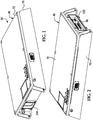
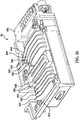
- the battery pack 10 includes a battery pack housing 30, a battery module 34, a thermally conductive housing 38, a DC/DC voltage converter 42, and an electric fan 46.
- An advantage of the battery pack 10 is that the battery pack 10 has the battery module 34 with end plates 230, 232 that extend past internal battery cells to direct air into heat exchangers contacting the battery cells. Thus, the battery pack 10 does not need a separate air manifold to direct air into heat exchangers contacting the battery cells.
- an advantage of the battery module 34 is that the battery module 34 utilizes at least one frame member which holds two battery cells on each side thereof and has an integrated cooling manifold for cooling the battery cells.
- the battery pack housing 30 is provided to hold the remaining components of the battery pack 10 therein.
- the battery pack housing 30 has a base portion 70 and an upper cover 72 which define an interior region 74.
- the interior region 74 includes an interior space 76 and an interior space 78.
- the base portion 70 includes a bottom wall 90 and side walls 92, 94, 96, 98.
- the side walls 92, 94, 96, 98 are coupled to the bottom wall 90 and extend upwardly substantially perpendicular to the bottom wall 90.
- the side walls 92, 94 extend substantially parallel to one another.
- the side walls 96, 98 extend substantially parallel to one another and perpendicular to the side walls 92, 94.
- the side wall 92 includes an inlet aperture 112 extending therethrough
- the side wall 94 includes an outlet aperture 114 extending therethrough.
- the base portion 70 is constructed of steel or aluminum. In an alternative embodiment, the base portion 70 is constructed of plastic.
- the upper cover 72 is removably coupled to the side walls 92, 94, 96, 98 to enclose the interior region 74.
- the upper cover 72 is constructed of steel or aluminum. In an alternative embodiment, the upper cover 72 is constructed of plastic.
- the battery module 34 is disposed in the interior space 76 of the interior region 74 of the battery pack housing 30 proximate to the inlet aperture 112.
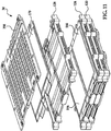
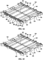
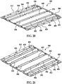
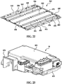
- the battery module 34 includes frame members 120, 124, 128, an insulating layer 140, battery cells 150, 154, 158, 162, 166, 170, 180, 184, 188, 192, 196, 200, battery cell interconnect assemblies 220, 222, and end plates 230, 232.
- the frame members 120, 124, 128 are provided to hold the battery cells 150-200 therebetween.
- the frame member 124 is coupled to and between the frame members 120, 128.
- the structure of each of the frame members 120, 124, 128 are identical to one another. Accordingly, only the structure of the frame member 120 will be described in detail below.
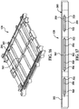
- the frame member 120 has a substantially rectangular ring-shaped outer plastic frame 260, central plastic walls 262, 263, and a heat exchanger 264.
- the heat exchanger 264 has first and second thermally conductive plates 360, 362 that are coupled together and define a flow path portion 540 that extends therethrough.
- the flow path portion 540 has flow path subportions 550, 552, 554, 556, 558, 560 each extending through the first and second thermally conductive plates 360, 362.
- the substantially rectangular ring-shaped outer plastic frame 260 is coupled around an outer peripheral region of the first and second thermally conductive plates 360, 362.
- the first substantially rectangular ring-shaped outer plastic frame 360 has first, second, third, and fourth side walls 280, 282, 284, 286.
- the first and second side walls 280, 282 extend substantially parallel to one another.
- the third and fourth side walls 284, 286 are coupled between the first and second side walls 280, 282 and extend substantially parallel to one another and perpendicular to the first and second side walls 280, 282.
- the central plastic wall 262 extends between the third and fourth side walls 284, 286 substantially parallel to the first and second side walls 280, 282.
- the central plastic wall 262 is disposed on a portion of the first side 380 (shown in FIG. 20 ) of the thermally conductive plate 360 of the heat exchanger 264.
- the central plastic wall 263 extends between the third and fourth side walls 284, 286 substantially parallel to the first and second side walls 280, 282.
- the central plastic wall 263 is disposed on a portion of the first side 480 (shown in FIG. 22 ) of the thermally conductive plate 362 of the heat exchanger 264.
- the first, third, and fourth side walls 280, 284, 286 and the central plastic wall 262 define a region for receiving a battery cell therein.
- the second, third, and fourth side walls 282, 284, 286 define a region for receiving another battery cell therein.
- the first side wall 280 has apertures 300, 302, 304 extending therethrough.
- the aperture 300 fluidly communicates with the flow path subportions 550, 552.
- the aperture 302 fluidly communicates with the flow path subportions 554, 556.
- the aperture 304 fluidly communicates with the flow path subportions 558, 560.
- the second side wall 282 has apertures 310, 312, 314 extending therethrough.
- the aperture 310 fluidly communicates with the flow path subportions 550, 552.
- the aperture 312 fluidly communicates with the flow path subportions 554, 556.
- the aperture 314 fluidly communicates with the flow path subportions 558, 560.
- the third side wall 284 has grooves 320, 322, 324, 326 extending therein.
- the fourth side wall 286 has grooves 330, 332, 334, 336 extending therein.
- the grooves 320, 330 are configured to receive first and second electrical terminals of a battery cell therethrough.
- the grooves 324, 334 are configured to receive first and second electrical terminals of another battery cell therethrough.
- the grooves 322, 332 are configured to receive first and second electrical terminals of another battery cell therethrough.
- the grooves 326, 336 are configured to receive first and second electrical terminals of another battery cell therethrough.
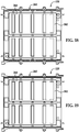
- the heat exchanger 264 includes first and second thermally conductive plates 360, 362 that are coupled together and define the flow path portion 540 extending completely through the plates 360, 362.
- the first thermally conductive plate 360 includes a sheet portion 370 having a first side 380 and a second side 382.
- the sheet portion 370 includes elongated depressed portions 390, 392, 394, 396, 398, 400, 402, 404, 406, 408, and depressed edge portions 410, 412.
- the sheet portion 370 is constructed of aluminum and is substantially rectangular-shaped.
- the second thermally conductive plate 362 includes a sheet portion 470 having a first side 480 and a second side 482.
- the sheet portion 470 includes elongated depressed portions 490, 492, 494, 496, 498, 500, 502, 504, 506, 508, and depressed edge portions 510, 512.
- the sheet portion 470 is constructed of aluminum and is substantially rectangular-shaped.
- the first thermally conductive plate 360 is coupled to the second thermally conductive plate 362 such that the elongated depressed portions 390, 392, 394, 396, 398, 400, 402, 404, 406, 408 contact and are coupled to the elongated depressed portions 490, 492, 494, 496, 498, 500, 502, 504, 506, 508, respectively and the depressed edge portions 410, 412 contact and are coupled to the depressed edge portions 510, 512.
- the plates 360, 362 define the flow path portion 540 having the flow path subportions 550, 552, 554, 556, 558, 560 that extending entirely through a longitudinal length of the plates 360, 362.
- the frame member 124 has an identical structure as the frame member 120 described above.
- the frame member 124 has a substantially rectangular ring-shaped outer plastic frame 570, first and second central plastic walls (not shown), and a heat exchanger 572.
- the frame member 128 has an identical structure as the frame member 120 described above.
- the frame member 128 has a substantially rectangular ring-shaped outer plastic frame 580, first and second central plastic walls (not shown), and a heat exchanger 582.
- the frame member 120 and the end plate 232 are configured to hold the battery cells 150, 180 therebetween. Further, the heat exchanger 264 of the frame member 120 is disposed between and contacts the battery cells 150, 154. Also, the heat exchanger 264 is disposed between and contacts the battery cells 180, 184.
- the frame members 120, 124 are configured to hold the battery cells 154, 158 therebetween. Further, the frame members 120, 124 are configured to hold the battery cells 184, 188 therebetween.
- the heat exchanger 572 of the frame member 124 is disposed between and contacts the battery cells 158, 162. Also, the heat exchanger 572 is disposed between and contacts the battery cells 188, 192.
- the frame members 124, 128 are configured to hold the battery cells 162, 166 therebetween. Further, the frame members 124, 128 are configured to hold the battery cells 192, 196 therebetween.
- the heat exchanger 582 of the frame member 128 is disposed between and contacts the battery cells 166. 170. Also, the heat exchanger 582 is disposed between and contacts the battery cells 196, 200.
- the frame member 128 and the insulating layer 140 are configured to hold the battery cells 170, 200 therebetween.
- the heat exchanger 582 of the frame member 128 is disposed against the battery cells 170, 200.
- the end plate 230 is coupled to the frame member 128 such that the insulating layer 140 is disposed between the frame member 128 and the battery cells 170, 200.
- the battery cells 150, 154, 158, 162, 166, 170, 180, 184, 188, 192, 196, 200 are each configured to generate an operational voltage.
- the battery cells 150-200 are pouch-type lithium-ion battery cells that have a substantially rectangular-shaped body portion and a pair of electrical terminals.
- the battery cells 150-200 are electrically coupled in series with one another utilizing interconnect members on the battery cell interconnect and voltage sensing assemblies 220, 222.
- the electrical terminals of the battery cells 150-200 are coupled to corresponding interconnect members by ultrasonically welding the electrical terminals of the battery cells 150-200 to the corresponding interconnect members utilizing an ultrasonic welding machine.
- the structure of the battery cells 150-200 are identical to one another.
- the battery cell 150 has a rectangular-shaped housing 640 with electrical terminals 642, 644, extending from first and second ends, respectively, of the housing 640.
- the electrical terminal 642 is electrically and physically coupled to the battery cell interconnect and voltage sensing assembly 220.
- the electrical terminal 644 is electrically and physically coupled to the battery cell interconnect and voltage sensing assembly 222.
- the battery cell 154 has a rectangular-shaped housing 650 with electrical terminals 652, 654, extending from first and second ends, respectively, of the housing 650.
- the electrical terminal 652 is electrically and physically coupled to the battery cell interconnect and voltage sensing assembly 220.
- the electrical terminal 654 is electrically and physically coupled to the battery cell interconnect and voltage sensing assembly 222.
- the battery cell 158 has a rectangular-shaped housing 660 with electrical terminals 662, 664, extending from first and second ends, respectively, of the housing 660.
- the electrical terminal 662 is electrically and physically coupled to the battery cell interconnect and voltage sensing assembly 220.
- the electrical terminal 664 is electrically and physically coupled to the battery cell interconnect and voltage sensing assembly 222.
- the battery cell 162 has a rectangular-shaped housing 670 with electrical terminals 672, 674, extending from first and second ends, respectively, of the housing 670.
- the electrical terminal 672 is electrically and physically coupled to the battery cell interconnect and voltage sensing assembly 220.
- the electrical terminal 674 is electrically and physically coupled to the battery cell interconnect and voltage sensing assembly 222.
- the battery cell 166 has a rectangular-shaped housing 680 with electrical terminals 682, 684, extending from first and second ends, respectively, of the housing 680.
- the electrical terminal 682 is electrically and physically coupled to the battery cell interconnect and voltage sensing assembly 220.
- the electrical terminal 684 is electrically and physically coupled to the battery cell interconnect and voltage sensing assembly 222.
- the battery cell 170 has a rectangular-shaped housing 690 with electrical terminals 692, 694, extending from first and second ends, respectively, of the housing 690.
- the electrical terminal 692 is electrically and physically coupled to the battery cell interconnect and voltage sensing assembly 220.
- the electrical terminal 694 is electrically and physically coupled to the battery cell interconnect and voltage sensing assembly 222.
- the series combination of the battery cells 150-170 are electrically coupled in series with the series combination of the battery cells 180-200 utilizing an elongated interconnect member.
- the battery cell 180 has a rectangular-shaped housing 700 with electrical terminals 702, 704 extending from first and second ends, respectively, of the housing 700.
- the electrical terminal 702 is electrically and physically coupled to the battery cell interconnect and voltage sensing assembly 220.
- the electrical terminal 704 is electrically and physically coupled to the battery cell interconnect and voltage sensing assembly 222.
- the battery cell 184 has a rectangular-shaped housing 710 with electrical terminals 712, 714 extending from first and second ends, respectively, of the housing 710.
- the electrical terminal 712 is electrically and physically coupled to the battery cell interconnect and voltage sensing assembly 220.
- the electrical terminal 714 is electrically and physically coupled to the battery cell interconnect and voltage sensing assembly 222.
- the battery cell 188 has a rectangular-shaped housing 720 with electrical terminals 722, 724 extending from first and second ends, respectively, of the housing 720.
- the electrical terminal 722 is electrically and physically coupled to the battery cell interconnect and voltage sensing assembly 220.
- the electrical terminal 724 is electrically and physically coupled to the battery cell interconnect and voltage sensing assembly 222.
- the battery cell 192 has a rectangular-shaped housing 730 with electrical terminals 732, 734 extending from first and second ends, respectively, of the housing 730.
- the electrical terminal 732 is electrically and physically coupled to the battery cell interconnect and voltage sensing assembly 220.
- the electrical terminal 734 is electrically and physically coupled to the battery cell interconnect and voltage sensing assembly 222.
- the battery cell 196 has a rectangular-shaped housing 740 with electrical terminals 742, 744 extending from first and second ends, respectively, of the housing 740.
- the electrical terminal 742 is electrically and physically coupled to the battery cell interconnect and voltage sensing assembly 220.
- the electrical terminal 744 is electrically and physically coupled to the battery cell interconnect and voltage sensing assembly 222.
- the battery cell 200 has a rectangular-shaped housing 750 with electrical terminals 752, 754 extending from first and second ends, respectively, of the housing 750.
- the electrical terminal 752 is electrically and physically coupled to the battery cell interconnect and voltage sensing assembly 220.
- the electrical terminal 754 is electrically and physically coupled to the battery cell interconnect and voltage sensing assembly 222.
- the end plates 230, 232 are provided to guide cooling air through the flow path portions 540, 574, 584 of the frame members 120, 124, 128, respectively.
- the end plates 230, 232 have the frame members 120-128 and the battery cells 150-200 disposed therebetween.
- the end plate 230 extends substantially parallel to a longitudinal axis 768 of the battery module 34.
- the end plate 230 has a first end portion 770 and a second end portion 772.
- the first end portion 770 extends longitudinally past a first end of each of the battery cells 150-170 toward the inlet aperture 112.
- the second end portion 772 extends longitudinally past the second end of each of the battery cells 180-200.
- the end plate 232 extends substantially parallel to the longitudinal axis 768 of the battery module 34.
- the end plate 232 has a first end portion 780 and a second end portion 782.
- the first end portion 780 extends longitudinally past a first end of each of the battery cells 150-170 toward the inlet aperture 112.
- the second end portion 782 extends longitudinally past the second end of each of the battery cells 180-200.
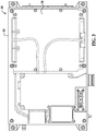
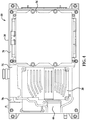
- the thermally conductive housing 38 is provided to hold the DC/DC voltage converter 42 therein that is electrically coupled to the battery cells of the battery module 34.
- the thermally conductive housing 38 transfers heat from the DC/DC voltage converter 42 to air flowing past the thermally conductive housing.
- the thermally conductive housing 38 is disposed in the interior space 78 of the interior region 74 of the battery pack housing 30 between the battery module 34 and the outlet aperture 114 of the battery pack housing 30.
- the thermally conductive housing 38 defines a flow path portion 804 between the thermally conductive housing 38 and the battery pack housing 30.
- the flow path portion 804 fluidly communicates with the flow path portions 540, 574, 584 of the battery module 34 and with the outlet aperture 114.
- the thermally conductive housing 38 includes a housing portion 800 and a frame member 802.
- the housing portion 800 includes bottom wall 810 and cooling fins 820, 822, 824, 826, 840, 842, 844, 846, 848 extending outwardly from the bottom wall 810 in a first direction.
- the cooling fins 820-848 are spaced apart from one another such that the flow path portion 804 is defined between the cooling fins 820-848.
- the cooling fins 820-848 are disposed on the bottom wall 90 (shown in FIG. 5 ) of the base portion 70.
- the thermally conductive housing 38 is constructed of aluminum.
- the thermally conductive housing 38 can be constructed of other materials such as steel or other metal alloys for example.
- the frame member 802 is coupled to an exterior of the thermally conductive housing 38 and includes an outlet portion 870 that directs air toward the fan 46 and the outlet aperture 114 of the battery pack housing 30.
- the electric fan 46 is disposed in the interior region 74 of the battery pack housing 30 proximate to the outlet aperture 114 of the battery pack housing 30.
- the electric fan 46 is adapted to urge air to flow through the inlet aperture 112 and through the flow path portions 540, 574, 584 of the battery module and the flow path portion 804 and further through a portion of the electric fan 46 and through the outlet aperture 114 of the battery pack housing 30.
- the electric fan 46 is disposed proximate to the inlet aperture 112.
- FIGS. 6 , 14 , 16, 17 and 27 a flowchart of a method of assembling a portion of the battery module 34 in accordance with another exemplary embodiment is provided.
- step 900 a user provides the battery cells 154, 184. After step 900, the method advances to step 902.
- the user provides the frame member 120 having the substantially rectangular ring-shaped outer plastic frame 260 and the heat exchanger 264.
- the heat exchanger 264 has first and second thermally conductive plates 360, 362 that are coupled together and define a flow path portion 540 (shown in FIG. 17 ) extending therethrough.
- the flow path portion 540 has at least flow path subportions 554, 558 extending through the first and second thermally conductive plates 360, 362.
- the substantially rectangular ring-shaped outer plastic frame 260 is coupled around an outer peripheral region of the first and second thermally conductive plates 360, 362.
- the substantially rectangular ring-shaped outer plastic frame 260 has first, second, third, and fourth side walls 280, 282, 284, 286.
- the first and second side walls 280, 282 extend substantially parallel to one another.
- the third and fourth side walls 284, 286 are coupled between the first and second side walls 280, 282 and extend substantially parallel to one another and perpendicular to the first and second side walls 280, 282.
- the first side wall 280 has apertures 302, 304 (shown in FIG. 14 ) extending therethrough that communicate with the flow path subportions 554, 558, respectively.
- the second side wall 282 has apertures 312, 314 (shown in FIG. 17 ) extending therethrough that communicate with the flow path subportions 554, 558, respectively.
- step 904 the user disposes the battery cell 154 on and against a first side of the first thermally conductive plate 360 of the heat exchanger 264. After step 904, the method advances to step 906.
- step 906 the user disposes the battery cell 184 on and against the first side of the first thermally conductive plate 360 of the heat exchanger 264.
- the battery cell 184 is further disposed proximate to the battery cell 154.
- step 908 the method advances to step 908.
- step 908 the user provides battery cells 158, 188 and the frame member 124 having the heat exchanger 572. After step 908, the method advances to step 910.
- step 910 the user disposes the battery cell 158 on and against the battery cell 154. After step 910, the method advances to step 912.
- step 912 the user disposes the battery cell 188 on and against the battery cell 184. After step 912, the method advances to step 914.
- the user disposes the heat exchanger 572 on the battery cells 158, 188.
- FIGS. 2 , 6 and 28 a flowchart of a method of assembling the battery pack 10 in accordance with another exemplary embodiment is provided.
- the user provides the battery pack housing 30, the battery module 34, the thermally conductive housing 38, and the electric fan 46.
- the battery pack housing 30 defines the interior region 74.
- the battery pack housing 30 further includes the inlet aperture 112 and the outlet aperture 114 communicating with the interior region 74.
- the battery module 34 has the battery cell 154, the heat exchanger 264, and end plates 230, 232.
- the battery cell 154 and the heat exchanger 264 are disposed against one another, and are further disposed between the end plates 230, 232.
- the heat exchanger 264 defines a flow path portion 540 therethrough.
- the battery cell 154 has a first end and a second end.
- the end plate 230 extends substantially parallel to the longitudinal axis 768 of the battery module 34.
- the end plate 230 has the first end portion 770 and the second end portion 772.
- the first end portion 770 of the end plate 230 extends longitudinally past the first end of the battery cell 154.
- the second end portion 772 of the end plate 230 extends longitudinally past the second end of the battery cell 154.
- the end plate 232 extends substantially parallel to the longitudinal axis 768 of the battery module 34.
- the end plate 232 having the first end portion 780 and the second end portion 782.
- the first end portion 780 of the end plate 232 extends longitudinally past the first end of the battery cell 154.
- the second end portion 782 of the end plate 232 extends longitudinally past the second end of the battery cell 154.
- step 932 the user disposes the battery module 34 in the interior region 74 of the battery pack housing 30 proximate to the inlet aperture 112. After step 932, the method advances to step 934.
- the user disposes the thermally conductive housing 38 in the interior region 74 of the battery pack housing 30 between the battery module 34 and the outlet aperture 114 of the battery pack housing 30.
- the thermally conductive housing 38 defines the path portion 804 between the thermally conductive housing 38 and the battery pack housing 30.
- the flow path portion 804 fluidly communicates with the flow path portion 540.
- the user disposes the electric fan 46 in the interior region 74 of the battery pack housing 30 proximate to the outlet aperture 114 of the battery pack housing 30.
- the electric fan 46 is adapted to urge air to flow through the inlet aperture 112 and through the path portions 540, 804 and further through a portion of the electric fan 46 and through the outlet aperture 114 of the battery pack housing 30.
- the battery module and the method of assembling the battery module provide a substantial advantage over other battery modules and methods.
- the battery module utilizes at least one frame member which holds two battery cells on each side thereof and has an integrated cooling manifold for cooling the battery cells.
Landscapes
- Chemical & Material Sciences (AREA)
- Chemical Kinetics & Catalysis (AREA)
- Electrochemistry (AREA)
- General Chemical & Material Sciences (AREA)
- Engineering & Computer Science (AREA)
- Manufacturing & Machinery (AREA)
- Secondary Cells (AREA)
- Battery Mounting, Suspending (AREA)
- Sealing Battery Cases Or Jackets (AREA)
Claims (11)
- Module de batterie (34), comprenant :une première cellule de batterie (170) ;un premier organe de cadre (128) ayant un premier cadre en plastique extérieur en forme d'anneau sensiblement rectangulaire (580) et un premier échangeur de chaleur (582) ;le premier échangeur de chaleur (582) ayant des première et seconde plaques thermiquement conductrices (360, 362) couplées ensemble et définissant une première portion de trajet d'écoulement (540) s'étendant au travers, la première portion de trajet d'écoulement ayant au moins des première et seconde sous-portions de trajet d'écoulement (550, 552 et 554, 556) s'étendant chacune à travers les première et seconde plaques thermiquement conductrices (360, 362) ;le premier cadre en plastique extérieur en forme d'anneau sensiblement rectangulaire (580) étant couplé autour d'une région périphérique extérieure des première et seconde plaques thermiquement conductrices (360, 362) ; le premier cadre en plastique extérieur en forme d'anneau sensiblement rectangulaire (580) ayant des première, deuxième, troisième et quatrième parois de côté (280, 282, 284, 286) ; les première et deuxième parois de côté (280, 282) s'étendant sensiblement parallèles l'une à l'autre ; les troisième et quatrième parois de côté (284, 286) étant couplées entre les première et deuxième parois de côté (280, 282) et s'étendant sensiblement parallèles l'une à l'autre et perpendiculaires aux première et deuxième parois de côté (280, 282) ; la première paroi de côté (280) ayant des première et deuxième ouvertures (300, 302) s'étendant au travers qui communiquent avec les première et seconde sous-portions de trajet d'écoulement (550, 552 et 554, 556), respectivement ; la deuxième paroi de côté (282) ayant des troisième et quatrième ouvertures (310, 312) s'étendant au travers qui communiquent avec les première et seconde sous-portions de trajet d'écoulement (550, 552 et 554, 556), respectivement ; la première cellule de batterie (170) étant disposée sur et contre un premier côté (380) de la première plaque thermiquement conductrice (360) ;caractérisé en ce que le module de batterie (34) comprend en outre une deuxième cellule de batterie (200) disposée sur et contre le premier côté (380) de la première plaque thermiquement conductrice (360), la deuxième cellule de batterie (200) étant en outre disposée à proximité de la première cellule de batterie (170), et en ce que une couche isolante (140) est disposée entre le premier organe de cadre (128) et les première et deuxième cellules de batterie (170, 200), l'organe de cadre (128) et la couche isolante (140) maintenant les cellules de batterie (170, 200) entre elles.
- Module de batterie (34) selon la revendication 1, dans lequel :le premier organe de cadre (128) comporte en outre une paroi en plastique centrale s'étendant entre les troisième et quatrième parois de côté (284, 286) sensiblement parallèles aux première et deuxième parois de côté (280, 282) ; la paroi en plastique centrale étant disposée sur une portion du premier côté (380) de la première plaque thermiquement conductrice (360) ;la première cellule de batterie (170) étant disposée sur et contre le premier côté (380) de la première plaque thermiquement conductrice (360) dans une première région définie par les première, troisième et quatrième parois de côté (280, 284, 286), et la paroi en plastique centrale ; etla deuxième cellule de batterie (200) étant disposée sur et contre le premier côté (380) de la première plaque thermiquement conductrice (360) adjacente à la première cellule de batterie (170) dans une seconde région définie par les deuxième, troisième et quatrième parois de côté (282, 284, 286), et la paroi en plastique centrale.
- Module de batterie (34) selon la revendication 1, dans lequel la première cellule de batterie (170) a un corps de forme sensiblement rectangulaire (690) et des première et seconde bornes électriques (692, 694) s'étendant vers l'extérieur depuis le corps de forme sensiblement rectangulaire (690).
- Module de batterie (34) selon la revendication 3, dans lequel la troisième paroi de côté (284) a une rainure (320) adaptée pour recevoir la première borne électrique (692) au travers ; et la quatrième paroi de côté (286) a une rainure (330) adaptée pour recevoir la seconde borne électrique (694) au travers.
- Module de batterie (34) selon la revendication 1, dans lequel les première et seconde plaques thermiquement conductrices (360, 362) sont construites chacune en aluminium.
- Module de batterie (34) selon la revendication 1, comprenant en outre des première et seconde plaques d'extrémité (230, 232) ; les première et deuxième cellules de batterie (170, 200) et le premier organe de cadre (128) étant disposés entre les première et seconde plaques d'extrémité (230, 232) ; la première cellule de batterie (170) ayant une première extrémité et une seconde extrémité ; la deuxième cellule de batterie (200) ayant une première extrémité et une seconde extrémité ;
la première plaque d'extrémité (230) s'étendant sensiblement parallèle à un axe longitudinal (768) du module de batterie (34), la première plaque d'extrémité (230) ayant une première portion d'extrémité (770) et une seconde portion d'extrémité (772), la première portion d'extrémité (770) de la première plaque d'extrémité (230) s'étendant longitudinalement au-delà de la première extrémité de la première cellule de batterie (170) et la première extrémité de la deuxième cellule de batterie (200) ; la seconde portion d'extrémité (772) de la première plaque d'extrémité (230) s'étendant longitudinalement au-delà de la seconde extrémité de la première cellule de batterie (170) et la seconde extrémité de la deuxième cellule de batterie (200) ; et
la seconde plaque d'extrémité (232) s'étendant sensiblement parallèle à l'axe longitudinal (768) du module de batterie (34), la seconde plaque d'extrémité (232) ayant une première portion d'extrémité (780) et une seconde portion d'extrémité (782), la première portion d'extrémité (780) de la seconde plaque d'extrémité (232) s'étendant longitudinalement au-delà de la première extrémité de la première cellule de batterie (170) et la première extrémité de la deuxième cellule de batterie (200) ; la seconde portion d'extrémité (782) de la seconde plaque d'extrémité (232) s'étendant longitudinalement au-delà de la seconde extrémité de la première cellule de batterie (170) et la seconde extrémité de la deuxième cellule de batterie (200). - Module de batterie (34) selon la revendication 6, dans lequel les première et seconde plaques d'extrémité (230, 232) sont construites chacune en plastique.
- Module de batterie (34) selon la revendication 1, comprenant en outre des troisième et quatrième cellules de batterie (158, 188) ; la troisième cellule de batterie (158) étant disposée sur et contre la première cellule de batterie (170) ; la quatrième cellule de batterie (188) étant disposée sur et contre la deuxième cellule de batterie (200).
- Module de batterie (34) selon la revendication 8, comprenant en outre un second organe de cadre (124) ayant un second échangeur de chaleur (572) disposé sur et contre les troisième et quatrième cellules de batterie (158 et 188).
- Procédé d'assemblage d'un module de batterie (34), comprenant :la fourniture d'une première cellule de batterie (170) ;la fourniture d'un premier organe de cadre (128) ayant un premier cadre en plastique extérieur en forme d'anneau sensiblement rectangulaire (580) et un premier échangeur de chaleur (582) ; le premier échangeur de chaleur (582) ayant des première et seconde plaques thermiquement conductrices (360, 362) couplées ensemble et définissant une première portion de trajet d'écoulement (540) s'étendant au travers, la première portion de trajet d'écoulement ayant au moins des première et seconde sous-portions de trajet d'écoulement (550, 552 et 554, 556) s'étendant chacune à travers les première et seconde plaques thermiquement conductrices (360, 362) ; le premier cadre en plastique extérieur en forme d'anneau sensiblement rectangulaire (580) étant couplé autour d'une région périphérique extérieure des première et seconde plaques thermiquement conductrices (360, 362) ; le premier cadre en plastique extérieur en forme d'anneau sensiblement rectangulaire (580) ayant des première, deuxième, troisième et quatrième parois de côté (280, 282, 284, 286) ; les première et deuxième parois de côté (280, 282) s'étendant sensiblement parallèles l'une à l'autre ; les troisième et quatrième parois de côté (284, 286) étant couplées entre les première et deuxième parois de côté (280, 282) et s'étendant sensiblement parallèles l'une à l'autre et perpendiculaires aux première et deuxième parois de côté (280, 282) ; la première paroi de côté (280) ayant des première et seconde ouvertures (300, 302) s'étendant au travers qui communiquent avec les première et seconde sous-portions de trajet d'écoulement (550, 552 et 554, 556), respectivement ; la deuxième paroi de côté (282) ayant des troisième et quatrième ouvertures (310, 312) s'étendant au travers qui communiquent avec les première et seconde sous-portions de trajet d'écoulement (550, 552 et 554, 556), respectivement ; la disposition de la première cellule de batterie (170) sur et contre un premier côté (380) de la première plaque thermiquement conductrice (360) ;caractérisé en ce que le procédé comprend en outre :la fourniture d'une deuxième cellule de batterie (200),la disposition de la deuxième cellule de batterie (200) sur et contre le premier côté (380) de la première plaque thermiquement conductrice (360), la deuxième cellule de batterie (200) étant en outre disposée à proximité de la première cellule de batterie (170), etla disposition d'une couche isolante (140) entre le premier organe de cadre (128) et les première et deuxième cellules de batterie (170, 200), l'organe de cadre (128) et la couche isolante (140) maintenant les cellules de batterie (170, 200) entre elles.
- Procédé selon la revendication 10, comprenant en outre :la fourniture de troisième et quatrième cellules de batterie (158 et 188) et d'un second organe de cadre (124), le second organe de cadre (124) ayant un second cadre en plastique extérieur en forme d'anneau sensiblement rectangulaire et un second échangeur de chaleur (572) ;la disposition de la troisième cellule de batterie (158) sur et contre la première cellule de batterie (170) ;la disposition de la quatrième cellule de batterie (188) sur et contre la deuxième cellule de batterie (200) ; etla disposition du second échangeur de chaleur (572) sur les troisième et quatrième cellules de batterie (158, 188).
Applications Claiming Priority (2)
| Application Number | Priority Date | Filing Date | Title |
|---|---|---|---|
| US14/273,586 US10770762B2 (en) | 2014-05-09 | 2014-05-09 | Battery module and method of assembling the battery module |
| PCT/KR2015/004505 WO2015170870A1 (fr) | 2014-05-09 | 2015-05-06 | Module de batterie et procédé d'assemblage d'un module de batterie |
Publications (3)
| Publication Number | Publication Date |
|---|---|
| EP3121893A4 EP3121893A4 (fr) | 2017-01-25 |
| EP3121893A1 EP3121893A1 (fr) | 2017-01-25 |
| EP3121893B1 true EP3121893B1 (fr) | 2018-07-04 |
Family
ID=54368593
Family Applications (1)
| Application Number | Title | Priority Date | Filing Date |
|---|---|---|---|
| EP15789675.4A Active EP3121893B1 (fr) | 2014-05-09 | 2015-05-06 | Module de batterie et procédé d'assemblage d'un module de batterie |
Country Status (6)
| Country | Link |
|---|---|
| US (1) | US10770762B2 (fr) |
| EP (1) | EP3121893B1 (fr) |
| JP (1) | JP6824551B2 (fr) |
| KR (1) | KR101968718B1 (fr) |
| CN (1) | CN106575805B (fr) |
| WO (1) | WO2015170870A1 (fr) |
Families Citing this family (5)
| Publication number | Priority date | Publication date | Assignee | Title |
|---|---|---|---|---|
| US9966641B2 (en) | 2015-12-29 | 2018-05-08 | Lg Chem, Ltd. | Battery pack |
| CN105762314B (zh) * | 2016-04-15 | 2019-01-08 | 宁德时代新能源科技股份有限公司 | 电芯缓冲结构及采用该结构的电池包 |
| CN106627199A (zh) * | 2016-11-02 | 2017-05-10 | 上海钧希新能源科技有限公司 | 一种车载级燃料电池控制板的固定结构 |
| CN110612616B (zh) * | 2017-05-31 | 2021-11-05 | 宁德时代新能源科技股份有限公司 | 固定架、电池模块以及电池包 |
| JP7183811B2 (ja) | 2019-01-24 | 2022-12-06 | Tdk株式会社 | 電池パック |
Family Cites Families (266)
| Publication number | Priority date | Publication date | Assignee | Title |
|---|---|---|---|---|
| DE436922C (de) | 1923-06-18 | 1926-11-11 | Fried Krupp Akt Ges Germaniawe | Kuehlvorrichtung fuer Akkumulatorenzellen |
| US2391859A (en) | 1931-11-07 | 1946-01-01 | Hoover Co | Room cooling device |
| GB481891A (en) | 1936-09-18 | 1938-03-18 | India Rubber Gutta Percha Tele | Improvements in or relating to containers for electric storage cells |
| US2210833A (en) | 1937-10-28 | 1940-08-06 | Gen Tire & Rubber Co | Sealing gasket |
| US2273244A (en) | 1940-04-03 | 1942-02-17 | Electric Storage Battery Co | Storage battery cell |
| SE319224B (fr) | 1966-12-19 | 1970-01-12 | Asea Ab | |
| US3503558A (en) | 1968-03-14 | 1970-03-31 | Electrolux Corp | Exhaust diffusion manifold for a vacuum cleaner or the like |
| US3550681A (en) | 1968-12-30 | 1970-12-29 | Gen Motors Corp | Self-adjusting thermal connector |
| US4009752A (en) | 1975-02-24 | 1977-03-01 | Honeywell Information Systems Inc. | Warp-resistant heat sink |
| US3964930A (en) | 1975-07-21 | 1976-06-22 | United Technologies Corporation | Fuel cell cooling system |
| US4063590A (en) | 1976-10-22 | 1977-12-20 | Mcconnell Christopher L | Preheater for clothes dryer |
| US4305456A (en) | 1977-08-12 | 1981-12-15 | Paul Mueller Company | Condenser and hot water system |
| US4298904A (en) | 1979-12-17 | 1981-11-03 | The Boeing Company | Electronic conduction cooling clamp |
| US4337626A (en) | 1980-05-01 | 1982-07-06 | Tyler Refrigeration Corporation | Well type refrigerated case with defrost air intake and colliding band air defrost |
| US4322776A (en) | 1980-08-04 | 1982-03-30 | Hughes Aircraft Company | Thermal interconnection |
| US4444994A (en) | 1982-01-29 | 1984-04-24 | Varo, Inc. | Electrically insulated quick disconnect heat sink |
| US4518663A (en) | 1983-07-01 | 1985-05-21 | Energy Development Associates, Inc. | Electrolyte circulation subsystem |
| GB8329269D0 (en) | 1983-11-02 | 1983-12-07 | British Aerospace | Electronic apparatus stowage |
| US4777561A (en) | 1985-03-26 | 1988-10-11 | Hughes Aircraft Company | Electronic module with self-activated heat pipe |
| FR2580433B1 (fr) | 1985-04-16 | 1987-08-14 | Socapex | Connecteur thermique pour carte de circuit imprime revetue de composants electroniques |
| US4849858A (en) | 1986-10-20 | 1989-07-18 | Westinghouse Electric Corp. | Composite heat transfer means |
| US4995240A (en) | 1987-01-27 | 1991-02-26 | Eaton Corporation | Controlling refrigeration having control module directly attached on valve body |
| US5057968A (en) | 1989-10-16 | 1991-10-15 | Lockheed Corporation | Cooling system for electronic modules |
| US4982785A (en) | 1990-03-06 | 1991-01-08 | Inter-City Products Corporation (Usa) | Serpentine heat exchanger |
| US5186250A (en) | 1990-05-11 | 1993-02-16 | Showa Aluminum Kabushiki Kaisha | Tube for heat exchangers and a method for manufacturing the tube |
| CH679620A5 (fr) | 1990-12-11 | 1992-03-13 | Sulzer Ag | |
| US5071652A (en) | 1990-12-11 | 1991-12-10 | Globe-Union Inc. | Metal oxide hydrogen battery having improved heat transfer properties |
| US5392873A (en) | 1992-01-22 | 1995-02-28 | Honda Giken Kogyo Kabushiki Kaisha | Structure for securing batteries used in an electric vehicle |
| US5214564A (en) | 1992-04-23 | 1993-05-25 | Sunstrand Corporation | Capacitor assembly with integral cooling apparatus |
| FR2697677B1 (fr) | 1992-11-02 | 1994-12-30 | Europ Accumulateurs | Batterie d'accumulateurs thermorégulée, notamment pour véhicule électrique. |
| JP2903913B2 (ja) | 1992-11-10 | 1999-06-14 | 松下電器産業株式会社 | 蓄電池システム |
| US5275012A (en) | 1993-01-07 | 1994-01-04 | Ford Motor Company | Climate control system for electric vehicle |
| US5356735A (en) | 1993-05-10 | 1994-10-18 | General Motors Corporation | Heated/cooled battery |
| US5329988A (en) | 1993-05-28 | 1994-07-19 | The Allen Group, Inc. | Heat exchanger |
| US5520976A (en) | 1993-06-30 | 1996-05-28 | Simmonds Precision Products Inc. | Composite enclosure for electronic hardware |
| US5472802A (en) | 1993-10-25 | 1995-12-05 | Ovonic Battery Company, Inc. | Sealed hydride batteries, including a new lid-terminal seal and electrode tab collecting comb |
| JP3260951B2 (ja) | 1994-02-23 | 2002-02-25 | 松下電器産業株式会社 | 密閉形アルカリ蓄電池の単電池及び単位電池 |
| US5663007A (en) | 1994-02-23 | 1997-09-02 | Matsushita Electric Industrial Co., Ltd. | Sealed storage battery and method for manufacturing the same |
| US5346786A (en) | 1994-03-21 | 1994-09-13 | Hodgetts Philip J | Modular rack mounted battery system |
| JPH08111244A (ja) | 1994-10-12 | 1996-04-30 | Nissan Motor Co Ltd | 積層型バッテリ装置 |
| JP3451141B2 (ja) | 1994-11-14 | 2003-09-29 | 本田技研工業株式会社 | バッテリ温度調節装置 |
| JP3451142B2 (ja) | 1994-11-18 | 2003-09-29 | 本田技研工業株式会社 | 温度制御機構を備えたバッテリ組立体 |
| US5620057A (en) | 1994-12-19 | 1997-04-15 | General Motors Corporation | Electric vehicle battery enclosure |
| US5586444A (en) | 1995-04-25 | 1996-12-24 | Tyler Refrigeration | Control for commercial refrigeration system |
| US5678421A (en) | 1995-12-26 | 1997-10-21 | Habco Beverage Systems Inc. | Refrigeration unit for cold space merchandiser |
| JP3745424B2 (ja) | 1995-11-06 | 2006-02-15 | 東芝電池株式会社 | 電池の製造方法 |
| JPH09199186A (ja) | 1996-01-22 | 1997-07-31 | Toyota Autom Loom Works Ltd | 蓄電池冷却構造体、蓄電池冷却構造体を使用した蓄電池モジュール、および蓄電池冷却方法 |
| JPH09219213A (ja) | 1996-02-09 | 1997-08-19 | Nissan Motor Co Ltd | 電気自動車用二次電池及びその温度上昇緩和装置 |
| JP3225192B2 (ja) | 1996-04-10 | 2001-11-05 | 本田技研工業株式会社 | バッテリの排気ガス制御システム |
| DE19639115C2 (de) | 1996-09-24 | 2003-08-07 | Behr Gmbh & Co | Plattenförmiges Wärmeübertragerelement |
| US5816062A (en) | 1997-01-15 | 1998-10-06 | Yu Feng Enterprise Co., Ltd. | Air conditioning system with supplemental ice storing and cooling capacity |
| JP3240973B2 (ja) | 1997-03-05 | 2001-12-25 | トヨタ自動車株式会社 | 車両用電池冷却システム |
| EP1030390B1 (fr) | 1997-03-24 | 2004-02-04 | Matsushita Electric Industrial Co., Ltd. | Batterie d'alimentation électrique |
| US6087036A (en) | 1997-07-25 | 2000-07-11 | 3M Innovative Properties Company | Thermal management system and method for a solid-state energy storing device |
| JP3830243B2 (ja) | 1997-10-06 | 2006-10-04 | トヨタ自動車株式会社 | 電池電源装置 |
| JP3790946B2 (ja) | 1997-12-08 | 2006-06-28 | 株式会社ヴァレオサーマルシステムズ | 熱交換器 |
| FR2774215B1 (fr) | 1998-01-29 | 2000-02-25 | Alsthom Cge Alcatel | Batterie monobloc etanche munie d'un dispositif de refroidissement |
| DE69815288T2 (de) | 1998-03-30 | 2004-05-06 | Renata Ag | Sicherheitsentlüftung für Akkumulator oder Batterie |
| US7264901B2 (en) | 1998-08-23 | 2007-09-04 | Ovonic Battery Company, Inc. | Monoblock battery |
| US6255015B1 (en) | 1998-08-23 | 2001-07-03 | Ovonic Battery Company, Inc. | Monoblock battery assembly |
| JP4231127B2 (ja) | 1998-09-03 | 2009-02-25 | パナソニック株式会社 | 集積電池の温度管理方法及びその装置 |
| US6176095B1 (en) | 1999-01-19 | 2001-01-23 | Carrier Corporation | Pretrip device for testing of a refrigeration system compressor |
| JP5025039B2 (ja) | 1999-07-07 | 2012-09-12 | 株式会社日本自動車部品総合研究所 | バッテリ温調装置 |
| JP4778602B2 (ja) | 1999-07-22 | 2011-09-21 | パナソニック株式会社 | 二次電池 |
| JP4416266B2 (ja) | 1999-10-08 | 2010-02-17 | パナソニック株式会社 | 密閉角形蓄電池 |
| JP4252172B2 (ja) | 1999-10-12 | 2009-04-08 | 株式会社日本自動車部品総合研究所 | バッテリ冷却装置 |
| US6399238B1 (en) | 1999-12-13 | 2002-06-04 | Alcatel | Module configuration |
| JP4921629B2 (ja) | 2000-03-31 | 2012-04-25 | パナソニック株式会社 | 流体冷却式電池パックシステム |
| US6560980B2 (en) | 2000-04-10 | 2003-05-13 | Thermo King Corporation | Method and apparatus for controlling evaporator and condenser fans in a refrigeration system |
| JP3777981B2 (ja) | 2000-04-13 | 2006-05-24 | トヨタ自動車株式会社 | 車両用電源装置 |
| WO2001080333A1 (fr) | 2000-04-13 | 2001-10-25 | Fmc Corporation | Bloc de batteries et batterie assurant une meilleure dissipation thermique |
| DE10021161A1 (de) | 2000-04-29 | 2001-10-31 | Vb Autobatterie Gmbh | Verfahren zur Ermittlung des Ladezustands und der Belastbarkeit eines elektrischen Akkumulators |
| JP4116238B2 (ja) | 2000-05-19 | 2008-07-09 | 株式会社タイカ | 電磁波遮蔽性を有する熱伝導性シート |
| US6462949B1 (en) | 2000-08-07 | 2002-10-08 | Thermotek, Inc. | Electronic enclosure cooling system |
| JP3727840B2 (ja) | 2000-09-29 | 2005-12-21 | 株式会社東芝 | 電池パック及び携帯用電子機器 |
| JP3576092B2 (ja) | 2000-11-10 | 2004-10-13 | 松下冷機株式会社 | 冷蔵庫 |
| JP3616005B2 (ja) | 2000-12-20 | 2005-02-02 | 本田技研工業株式会社 | ハイブリッド車両の冷却装置 |
| FR2819036B1 (fr) | 2001-01-04 | 2004-01-16 | Cit Alcatel | Soupape et generateur electrochimique comprenant une telle soupape |
| US6569556B2 (en) | 2001-01-29 | 2003-05-27 | General Motors Corporation | Cooling system for a battery pack |
| JP4892788B2 (ja) | 2001-04-23 | 2012-03-07 | トヨタ自動車株式会社 | 電池モジュール |
| US6422027B1 (en) | 2001-05-03 | 2002-07-23 | Ford Global Tech., Inc. | System and method for cooling a battery pack |
| CN1194436C (zh) | 2001-05-11 | 2005-03-23 | 上海神力科技有限公司 | 一种改进型燃料电池 |
| US6506111B2 (en) | 2001-05-16 | 2003-01-14 | Sanmina-Sci Corporation | Cooling airflow distribution device |
| JP4361229B2 (ja) | 2001-07-04 | 2009-11-11 | 日産自動車株式会社 | 電池システム |
| JP3850688B2 (ja) | 2001-07-19 | 2006-11-29 | 松下電器産業株式会社 | 角形電池及び組電池の冷却装置 |
| US6512347B1 (en) | 2001-10-18 | 2003-01-28 | General Motors Corporation | Battery having an integral cooling system |
| JP3969254B2 (ja) | 2001-10-29 | 2007-09-05 | 株式会社デンソー | バッテリ温度管理装置 |
| JP2003188323A (ja) | 2001-12-19 | 2003-07-04 | Sony Corp | グラファイトシート及びその製造方法 |
| WO2003054465A1 (fr) | 2001-12-21 | 2003-07-03 | Behr Gmbh & Co. | Dispositif d'echange de chaleur |
| KR20100088625A (ko) | 2002-02-19 | 2010-08-09 | 쓰리엠 이노베이티브 프로퍼티즈 컴파니 | 고에너지 전기 화학 전지를 위한 온도 제어 장치 및 방법 |
| US6821671B2 (en) | 2002-03-01 | 2004-11-23 | Lg Chem, Ltd. | Method and apparatus for cooling and positioning prismatic battery cells |
| JP2003282112A (ja) | 2002-03-26 | 2003-10-03 | Denso Corp | 燃料電池用の中間熱交換器 |
| JP3733079B2 (ja) | 2002-03-29 | 2006-01-11 | 三洋電機株式会社 | 低温貯蔵庫 |
| JP4041334B2 (ja) | 2002-04-08 | 2008-01-30 | 株式会社不二工機 | 膨張弁及び冷凍サイクル |
| US6889762B2 (en) | 2002-04-29 | 2005-05-10 | Bergstrom, Inc. | Vehicle air conditioning and heating system providing engine on and engine off operation |
| JP4242665B2 (ja) | 2002-05-13 | 2009-03-25 | パナソニック株式会社 | 組電池の冷却装置及び二次電池 |
| KR100471233B1 (ko) | 2002-06-26 | 2005-03-10 | 현대자동차주식회사 | 하이브리드 전기자동차 배터리의 최대 충전 및 방전전류값 생성방법 |
| CA2392610C (fr) | 2002-07-05 | 2010-11-02 | Long Manufacturing Ltd. | Echangeur de chaleur refroidi par parois cloisonnees |
| US7010644B2 (en) | 2002-08-29 | 2006-03-07 | Micron Technology, Inc. | Software refreshed memory device and method |
| CA2445622C (fr) | 2002-10-18 | 2011-06-28 | Habco Beverage Systems Inc. | Groupe frigorifique modulaire et refrigerateur |
| US7070874B2 (en) | 2002-12-24 | 2006-07-04 | Fuelcell Energy, Inc. | Fuel cell end unit with integrated heat exchanger |
| WO2004077590A2 (fr) | 2003-02-27 | 2004-09-10 | Protonex Technology Corporation | Piles de cellules electrochimiques a membranes a collecteurs exterieurs |
| JP3867060B2 (ja) | 2003-03-28 | 2007-01-10 | 三菱電機株式会社 | 車両用電源システム |
| JP2004333115A (ja) | 2003-04-16 | 2004-11-25 | Showa Denko Kk | 熱交換器およびその製造方法 |
| TWI309290B (en) | 2003-05-30 | 2009-05-01 | Sanyo Electric Co | Cooling apparatus |
| US20050026014A1 (en) | 2003-07-31 | 2005-02-03 | Michael Fogaing | Polymer batteries having thermal exchange apparatus |
| JP4045340B2 (ja) | 2003-08-13 | 2008-02-13 | 現代自動車株式会社 | バッテリー有効パワー算出方法及び算出システム |
| JP4578867B2 (ja) | 2003-09-30 | 2010-11-10 | 株式会社日立製作所 | 水素貯蔵・供給装置とそのシステム及びそれを用いた分散電源並びに自動車 |
| US7270910B2 (en) | 2003-10-03 | 2007-09-18 | Black & Decker Inc. | Thermal management systems for battery packs |
| US6826948B1 (en) | 2003-10-09 | 2004-12-07 | Delphi Technologies, Inc. | Leak detection apparatus for a liquid circulation cooling system |
| JP3972884B2 (ja) * | 2003-10-10 | 2007-09-05 | 日産自動車株式会社 | 組電池 |
| JP4078553B2 (ja) | 2003-10-21 | 2008-04-23 | 新神戸電機株式会社 | 車両用リチウム電池モジュール |
| JP2005147443A (ja) | 2003-11-12 | 2005-06-09 | Calsonic Kansei Corp | 積層型熱交換器 |
| JP3784813B2 (ja) | 2003-11-26 | 2006-06-14 | 本田技研工業株式会社 | 車両モータ用高圧電装の冷却装置及びハイブリッド車両 |
| US20050134038A1 (en) | 2003-12-17 | 2005-06-23 | Eaton Corporation | Fitting for fluid conveyance |
| US7237395B2 (en) | 2003-12-22 | 2007-07-03 | General Electric Company | Methods and apparatus for controlling refrigerators |
| KR100799866B1 (ko) | 2004-03-16 | 2008-01-31 | 주식회사 엘지화학 | 안전성이 우수한 이차 전지 |
| JP4570888B2 (ja) | 2004-03-18 | 2010-10-27 | 富士重工業株式会社 | 蓄電体装置 |
| JP2005349955A (ja) | 2004-06-10 | 2005-12-22 | Toyota Motor Corp | 蓄電機構の冷却構造 |
| JP4707346B2 (ja) | 2004-08-16 | 2011-06-22 | 三洋電機株式会社 | 車両用の電源装置 |
| US20080248338A1 (en) | 2004-10-05 | 2008-10-09 | Masaya Yano | Fuel Cell and Power Generating Method |
| KR101088081B1 (ko) | 2004-10-29 | 2011-11-30 | 한라공조주식회사 | 열교환기 |
| JP2006139928A (ja) | 2004-11-10 | 2006-06-01 | Nissan Motor Co Ltd | バッテリシステム |
| KR100637472B1 (ko) | 2004-12-07 | 2006-10-23 | 삼성에스디아이 주식회사 | 이차 전지 모듈 |
| KR100876458B1 (ko) | 2004-12-24 | 2008-12-29 | 주식회사 엘지화학 | 신규한 구조의 전지 카트리지와 그것을 포함하고 있는개방형 전지 모듈 |
| US7931073B2 (en) | 2005-02-02 | 2011-04-26 | Carrier Corporation | Heat exchanger with fluid expansion in header |
| JP2006236826A (ja) | 2005-02-25 | 2006-09-07 | Toyota Motor Corp | 電池パック |
| CA2600595C (fr) | 2005-03-16 | 2013-07-23 | Ford Global Technologies, Llc | Systeme d'alimentation electrique |
| US7716937B2 (en) | 2005-03-17 | 2010-05-18 | Electrolux Home Products, Inc. | Electronic refrigeration control system including a variable speed compressor |
| KR100965049B1 (ko) | 2005-03-23 | 2010-06-21 | 에스케이에너지 주식회사 | 고출력 리튬 2차 전지 유닛셀의 적층 구조 |
| KR20060102853A (ko) | 2005-03-25 | 2006-09-28 | 삼성에스디아이 주식회사 | 이차 전지 모듈 |
| US9653748B2 (en) | 2005-04-14 | 2017-05-16 | Enerdel, Inc. | Apparatus and method for securing battery cell packs |
| AU2006201260B2 (en) | 2005-04-19 | 2011-09-15 | Fisher & Paykel Appliances Limited | Linear Compressor Controller |
| US7278389B2 (en) | 2005-04-19 | 2007-10-09 | Murat Kirakosyan | Automobile intake air flow plenum and plenum diverter |
| KR100880386B1 (ko) | 2005-06-03 | 2009-01-23 | 주식회사 엘지화학 | 신규한 구조의 이차전지 및 이를 포함하는 전지팩 |
| JP4415910B2 (ja) | 2005-07-12 | 2010-02-17 | トヨタ自動車株式会社 | ハイブリッド車両の構造 |
| KR100765659B1 (ko) | 2005-08-09 | 2007-10-10 | 현대자동차주식회사 | 자동차용 연료전지 스택 구조 |
| JP2007048750A (ja) | 2005-08-10 | 2007-02-22 | Samsung Sdi Co Ltd | 電池モジュール |
| JP4600212B2 (ja) | 2005-08-23 | 2010-12-15 | 株式会社デンソー | 超臨界冷凍サイクル装置 |
| US7658224B2 (en) | 2005-09-19 | 2010-02-09 | Dana Canada Corporation | Flanged connection for heat exchanger |
| JP2007107684A (ja) | 2005-10-17 | 2007-04-26 | Nsk Ltd | リニアガイド装置のエンドキャップ |
| US20070087266A1 (en) | 2005-10-18 | 2007-04-19 | Debbi Bourke | Modular battery system |
| US8030886B2 (en) | 2005-12-21 | 2011-10-04 | Nuventix, Inc. | Thermal management of batteries using synthetic jets |
| KR100948003B1 (ko) | 2006-02-27 | 2010-03-18 | 주식회사 엘지화학 | 우수한 냉각 효율성의 중대형 전지팩 |
| US20070209378A1 (en) | 2006-03-10 | 2007-09-13 | Larson Gerald L | Vehicle integrated power and control strategy for cold plate refrigeration system |
| DE102006015568B3 (de) | 2006-04-04 | 2007-05-31 | Daimlerchrysler Ag | Verfahren zur Herstellung eines Wärmetauscher-Moduls für Wärmetauscher für elektrochemische Energiespeicher, sowie Vorrichtung zur Durchführung des Verfahrens |
| JP4857896B2 (ja) | 2006-05-11 | 2012-01-18 | トヨタ自動車株式会社 | 組電池および車両 |
| DE102007028252B4 (de) | 2006-06-26 | 2017-02-02 | Denso Corporation | Kältemittelkreisvorrichtung mit Ejektorpumpe |
| CN101101997A (zh) | 2006-07-05 | 2008-01-09 | 大同股份有限公司 | 燃料电池及其组装方法 |
| JP2008054379A (ja) | 2006-08-22 | 2008-03-06 | Calsonic Kansei Corp | 車両用バッテリ冷却システム |
| JP4251204B2 (ja) | 2006-08-31 | 2009-04-08 | 日産自動車株式会社 | 電池モジュール |
| JP2008062875A (ja) | 2006-09-11 | 2008-03-21 | Calsonic Kansei Corp | 車両用バッテリ冷却システム |
| KR100921346B1 (ko) | 2006-09-25 | 2009-10-13 | 주식회사 엘지화학 | 중대형 전지모듈 및 전지모듈 어셈블리 |
| JP2008080995A (ja) | 2006-09-28 | 2008-04-10 | Denso Corp | 冷却システム |
| US7531270B2 (en) | 2006-10-13 | 2009-05-12 | Enerdel, Inc. | Battery pack with integral cooling and bussing devices |
| KR100889241B1 (ko) | 2006-10-23 | 2009-03-17 | 주식회사 엘지화학 | 전지모듈의 전극단자 접속부재 |
| US20080226976A1 (en) | 2006-11-01 | 2008-09-18 | Eveready Battery Company, Inc. | Alkaline Electrochemical Cell with Reduced Gassing |
| US7797958B2 (en) | 2006-11-15 | 2010-09-21 | Glacier Bay, Inc. | HVAC system controlled by a battery management system |
| KR101064240B1 (ko) | 2006-11-27 | 2011-09-14 | 주식회사 엘지화학 | 열복사 방지 구조를 포함하고 있는 전원 시스템 |
| JP2008159439A (ja) | 2006-12-25 | 2008-07-10 | Toyota Motor Corp | 蓄電モジュール |
| JP2008159440A (ja) | 2006-12-25 | 2008-07-10 | Calsonic Kansei Corp | 車両用バッテリ冷却システム |
| US8268505B2 (en) | 2007-01-25 | 2012-09-18 | Honda Motor Co., Ltd. | Fuel cell system |
| DE102007004567A1 (de) | 2007-01-30 | 2008-07-31 | Robert Bosch Gmbh | Vorrichtung mit wenigstens einer elektrochemischen Zelle |
| EP2136167A1 (fr) | 2007-03-13 | 2009-12-23 | Hoshizaki Denki Kabushiki Kaisha | Chambre de stockage de refroidissement et son procédé de fonctionnement |
| KR100942985B1 (ko) | 2007-03-21 | 2010-02-17 | 주식회사 엘지화학 | 냉매 유량의 분배 균일성이 향상된 중대형 전지팩 케이스 |
| JP2008251378A (ja) | 2007-03-30 | 2008-10-16 | Toyota Motor Corp | 電池パックの冷却構造 |
| KR101212362B1 (ko) | 2007-04-04 | 2012-12-13 | 에스케이이노베이션 주식회사 | 열전 반도체소자를 이용한 전기 자동차의 배터리 온도 조절장치 |
| JP5236210B2 (ja) | 2007-05-10 | 2013-07-17 | カルソニックカンセイ株式会社 | バッテリの電池モジュール構造 |
| US7846573B2 (en) | 2007-06-01 | 2010-12-07 | Cobasys, Llc | Coolant manifold |
| JP4438830B2 (ja) | 2007-06-19 | 2010-03-24 | コニカミノルタビジネステクノロジーズ株式会社 | 樹脂組成物、成形体、電子写真用転写ベルト、および画像形成装置 |
| KR101141057B1 (ko) | 2007-06-28 | 2012-05-03 | 주식회사 엘지화학 | 중대형 전지팩 |
| JP5137480B2 (ja) | 2007-06-29 | 2013-02-06 | 三洋電機株式会社 | 車両用の電源装置 |
| JP2009054297A (ja) | 2007-08-23 | 2009-03-12 | Toshiba Corp | 電池パック |
| JP4508221B2 (ja) | 2007-08-27 | 2010-07-21 | 豊田合成株式会社 | 組電池装置 |
| DE102007045183A1 (de) | 2007-09-21 | 2009-04-02 | Robert Bosch Gmbh | Temperierte Batterieeinrichtung und Verfahren hierzu |
| KR100872225B1 (ko) | 2007-11-05 | 2008-12-05 | 엘지전자 주식회사 | 냉장고의 제어방법 |
| US8846231B2 (en) * | 2007-11-07 | 2014-09-30 | Enerdel, Inc. | Battery assembly with temperature control device |
| KR100949334B1 (ko) | 2007-11-12 | 2010-03-26 | 삼성에스디아이 주식회사 | 전지 모듈 |
| US9283826B2 (en) | 2007-11-13 | 2016-03-15 | Mahle International Gmbh | Device for cooling a heat source of a motor vehicle |
| US8409743B2 (en) | 2007-11-28 | 2013-04-02 | Sanyo Electric Co., Ltd. | Battery system with battery cells arranged in array alignment |
| JP5147373B2 (ja) | 2007-11-29 | 2013-02-20 | 三洋電機株式会社 | バッテリシステム |
| CN101904042B (zh) | 2007-12-05 | 2014-11-05 | 埃纳德尔公司 | 带温度控制装置的电池组件 |
| JP2009158316A (ja) | 2007-12-27 | 2009-07-16 | Calsonic Kansei Corp | バッテリ冷却装置 |
| US8628872B2 (en) | 2008-01-18 | 2014-01-14 | Lg Chem, Ltd. | Battery cell assembly and method for assembling the battery cell assembly |
| DE102008011466A1 (de) | 2008-02-27 | 2009-09-03 | Robert Bosch Gmbh | Batteriemodul |
| WO2009119037A1 (fr) | 2008-03-24 | 2009-10-01 | 三洋電機株式会社 | Dispositif de batterie et unité de batterie |
| JP5258348B2 (ja) | 2008-03-27 | 2013-08-07 | 三洋電機株式会社 | 車両用の電源装置 |
| KR20090107443A (ko) | 2008-04-08 | 2009-10-13 | 쏘씨에떼 드 베이뀔르 엘렉트리끄 | 가요성의 발전 소자와 상기 발전 소자들의 기계적, 열적 조절 시스템을 포함하는 전기 배터리 |
| US7851080B2 (en) | 2008-04-09 | 2010-12-14 | Gm Global Technology Operations, Inc. | Battery cooling plate design with discrete channels |
| US8465863B2 (en) | 2008-04-09 | 2013-06-18 | GM Global Technology Operations LLC | Batteries and components thereof and methods of making and assembling the same |
| US8215432B2 (en) | 2008-05-09 | 2012-07-10 | GM Global Technology Operations LLC | Battery thermal system for vehicle |
| US8486552B2 (en) | 2008-06-30 | 2013-07-16 | Lg Chem, Ltd. | Battery module having cooling manifold with ported screws and method for cooling the battery module |
| US8426050B2 (en) | 2008-06-30 | 2013-04-23 | Lg Chem, Ltd. | Battery module having cooling manifold and method for cooling battery module |
| US9759495B2 (en) | 2008-06-30 | 2017-09-12 | Lg Chem, Ltd. | Battery cell assembly having heat exchanger with serpentine flow path |
| US9140501B2 (en) | 2008-06-30 | 2015-09-22 | Lg Chem, Ltd. | Battery module having a rubber cooling manifold |
| US8067111B2 (en) | 2008-06-30 | 2011-11-29 | Lg Chem, Ltd. | Battery module having battery cell assembly with heat exchanger |
| US7883793B2 (en) | 2008-06-30 | 2011-02-08 | Lg Chem, Ltd. | Battery module having battery cell assemblies with alignment-coupling features |
| DE102008034860B4 (de) | 2008-07-26 | 2011-07-14 | Daimler AG, 70327 | Batterie mit einem Batteriegehäuse und einer Wärmeleitplatte zum Temperieren der Batterie |
| EP2200109B1 (fr) | 2008-12-12 | 2015-01-07 | Behr GmbH & Co. KG | Dispositif de retenue et de refroidissement pour une cellule galvanique |
| DE102009005124A1 (de) | 2009-01-19 | 2010-07-29 | Li-Tec Battery Gmbh | Elektrochemische Energiespeichervorrichtung |
| DE102009005854A1 (de) | 2009-01-23 | 2010-07-29 | Li-Tec Battery Gmbh | Batteriezelle mit Umhüllung |
| DE102009006426A1 (de) | 2009-01-28 | 2010-07-29 | Li-Tec Battery Gmbh | Batterie mit Gehäuse |
| EP2634028B1 (fr) | 2009-03-30 | 2017-01-11 | MAHLE Behr GmbH & Co. KG | Dispositif de liaison thermique d'un accumulateur d'énergie |
| US9337456B2 (en) | 2009-04-20 | 2016-05-10 | Lg Chem, Ltd. | Frame member, frame assembly and battery cell assembly made therefrom and methods of making the same |
| US8663829B2 (en) | 2009-04-30 | 2014-03-04 | Lg Chem, Ltd. | Battery systems, battery modules, and method for cooling a battery module |
| US8852778B2 (en) | 2009-04-30 | 2014-10-07 | Lg Chem, Ltd. | Battery systems, battery modules, and method for cooling a battery module |
| US20100275619A1 (en) | 2009-04-30 | 2010-11-04 | Lg Chem, Ltd. | Cooling system for a battery system and a method for cooling the battery system |
| US8403030B2 (en) | 2009-04-30 | 2013-03-26 | Lg Chem, Ltd. | Cooling manifold |
| ITBO20090427A1 (it) | 2009-07-02 | 2011-01-03 | Ferrari Spa | Veicolo a trazione elettrica con raffreddamento mediante ciclo frigorifero |
| US8399118B2 (en) | 2009-07-29 | 2013-03-19 | Lg Chem, Ltd. | Battery module and method for cooling the battery module |
| US8703318B2 (en) | 2009-07-29 | 2014-04-22 | Lg Chem, Ltd. | Battery module and method for cooling the battery module |
| US8399119B2 (en) | 2009-08-28 | 2013-03-19 | Lg Chem, Ltd. | Battery module and method for cooling the battery module |
| JP4877373B2 (ja) | 2009-08-28 | 2012-02-15 | 日産自動車株式会社 | 組電池および組電池の製造方法 |
| KR20110024954A (ko) | 2009-09-03 | 2011-03-09 | 삼성전자주식회사 | 냉각용 유로를 갖는 이차 전지 모듈 |
| JP5496604B2 (ja) * | 2009-10-30 | 2014-05-21 | 三洋電機株式会社 | 電源装置及びこれを備える車両 |
| KR101093959B1 (ko) | 2010-02-04 | 2011-12-15 | 에스비리모티브 주식회사 | 전지 모듈의 방열 장치 |
| KR101230954B1 (ko) | 2010-04-08 | 2013-02-07 | 주식회사 엘지화학 | 신규한 구조의 센싱부재를 포함하는 전지모듈 |
| DE102010020065A1 (de) * | 2010-05-11 | 2011-11-17 | Bayerische Motoren Werke Aktiengesellschaft | Energiespeichermodul aus mehreren prismatischen Speicherzellen und Verfahren zur Herstellung eines Energiespeichermoduls |
| KR101205180B1 (ko) | 2010-05-18 | 2012-11-27 | 주식회사 엘지화학 | 콤팩트하고 안정성이 우수한 냉각부재와 이를 포함하는 전지모듈 |
| CN203398243U (zh) | 2010-05-21 | 2014-01-15 | 格拉弗技术国际控股有限公司 | 用于具有相对主表面的电池单元的热管理组件 |
| EP2390951A1 (fr) | 2010-05-26 | 2011-11-30 | MANN+HUMMEL GmbH | Module de transfert de chaleur pour cellules de batterie et ensemble de batterie le comprenant |
| US9065158B2 (en) | 2010-05-28 | 2015-06-23 | GM Global Technology Operations LLC | Corrugated fin and frame assembly for battery cooling |
| DE102010021922A1 (de) | 2010-05-28 | 2011-12-01 | Li-Tec Battery Gmbh | Kühlelement und Verfahren zum Herstellen desselben; elektrochemische Energiespeichervorrichtung mit Kühlelement |
| US8460815B2 (en) | 2010-05-28 | 2013-06-11 | GM Global Technology Operations LLC | Stackable repeating frame with integrated cell sensing connection |
| KR101156527B1 (ko) | 2010-06-01 | 2012-06-21 | 에스비리모티브 주식회사 | 전지팩 |
| JP5464168B2 (ja) | 2010-06-04 | 2014-04-09 | 株式会社デンソー | 電源装置 |
| US9196938B2 (en) | 2010-07-06 | 2015-11-24 | Samsung Sdi Co., Ltd. | Battery module |
| DE102010032899A1 (de) | 2010-07-30 | 2012-02-02 | Valeo Klimasysteme Gmbh | Kühlvorrichtung für eine Fahrzeugbatterie sowie Fahrzeugbatteriebaugruppe mit einer solchen Kühlvorrichtung |
| US8673473B2 (en) | 2010-08-10 | 2014-03-18 | GM Global Technology Operations LLC | Integrated cooling fin and frame |
| JP5606872B2 (ja) | 2010-08-20 | 2014-10-15 | 愛三工業株式会社 | 電池モジュール |
| US8662153B2 (en) * | 2010-10-04 | 2014-03-04 | Lg Chem, Ltd. | Battery cell assembly, heat exchanger, and method for manufacturing the heat exchanger |
| KR101243908B1 (ko) | 2010-10-12 | 2013-03-14 | 삼성에스디아이 주식회사 | 단위 전지 및 전지 모듈 |
| CN201859929U (zh) | 2010-10-27 | 2011-06-08 | 法雷奥汽车空调湖北有限公司 | 电动汽车用动力电池的冷却液及加热装置 |
| KR101252944B1 (ko) | 2011-03-08 | 2013-04-15 | 로베르트 보쉬 게엠베하 | 방열 특성이 향상된 배터리 팩 |
| KR101247462B1 (ko) | 2011-05-20 | 2013-03-25 | 세방전지(주) | 전지냉각용 전지팩 |
| JP5484403B2 (ja) * | 2011-06-08 | 2014-05-07 | 本田技研工業株式会社 | バッテリモジュール |
| KR101469518B1 (ko) | 2011-08-01 | 2014-12-05 | 주식회사 엘지화학 | 안전성이 향상된 전지모듈 |
| KR20130017289A (ko) | 2011-08-10 | 2013-02-20 | 현대자동차주식회사 | 고전압 배터리팩용 배터리 모듈 |
| WO2013025608A1 (fr) | 2011-08-15 | 2013-02-21 | Graftech International Holdings Inc. | Ensemble bloc-pile |
| WO2013031613A1 (fr) | 2011-08-26 | 2013-03-07 | 三洋電機株式会社 | Dispositif d'alimentation électrique ainsi que véhicule équipé de celui-ci, et dispositif de stockage |
| US8974938B2 (en) | 2011-08-30 | 2015-03-10 | Lg Chem, Ltd. | Battery system and method for coupling a battery cell assembly to an electrically non-conductive base member |
| KR20130033531A (ko) | 2011-09-27 | 2013-04-04 | 에스케이이노베이션 주식회사 | 배터리 모듈 |
| KR101883915B1 (ko) | 2011-09-30 | 2018-08-02 | 삼성에스디아이 주식회사 | 지지부재를 포함하는 배터리 모듈 |
| US8512890B2 (en) | 2011-11-07 | 2013-08-20 | Bren-Tronics Batteries International, L.L.C. | Lithium ion cell with cooling features |
| KR20130054715A (ko) | 2011-11-17 | 2013-05-27 | 삼성전기주식회사 | 전지팩 케이스 |
| JP5768683B2 (ja) | 2011-11-28 | 2015-08-26 | 富士通株式会社 | 受信データ処理方法、通信装置、及びプログラム |
| KR101750066B1 (ko) | 2011-12-02 | 2017-06-23 | 에스케이이노베이션 주식회사 | 수냉식 이차전지 |
| KR101382011B1 (ko) | 2011-12-23 | 2014-04-15 | 세방전지(주) | 이차 전지팩 |
| US9379420B2 (en) | 2012-03-29 | 2016-06-28 | Lg Chem, Ltd. | Battery system and method for cooling the battery system |
| US9105950B2 (en) | 2012-03-29 | 2015-08-11 | Lg Chem, Ltd. | Battery system having an evaporative cooling member with a plate portion and a method for cooling the battery system |
| TWM435052U (en) * | 2012-05-17 | 2012-08-01 | Asia Vital Components Co Ltd | In the battery pack water-cooling plate unit |
| US8852781B2 (en) | 2012-05-19 | 2014-10-07 | Lg Chem, Ltd. | Battery cell assembly and method for manufacturing a cooling fin for the battery cell assembly |
| KR101987773B1 (ko) | 2012-07-16 | 2019-06-11 | 에스케이이노베이션 주식회사 | 전지팩 |
| US9306199B2 (en) | 2012-08-16 | 2016-04-05 | Lg Chem, Ltd. | Battery module and method for assembling the battery module |
| US9960395B2 (en) | 2012-08-16 | 2018-05-01 | Lg Chem, Ltd. | Battery module |
| US20140120390A1 (en) | 2012-10-31 | 2014-05-01 | Lg Chem, Ltd. | Battery cell assembly and method for manufacturing a cooling fin for the battery cell assembly |
| US9083066B2 (en) | 2012-11-27 | 2015-07-14 | Lg Chem, Ltd. | Battery system and method for cooling a battery cell assembly |
| US8852783B2 (en) | 2013-02-13 | 2014-10-07 | Lg Chem, Ltd. | Battery cell assembly and method for manufacturing the battery cell assembly |
| KR101572447B1 (ko) | 2013-03-19 | 2015-11-27 | 주식회사 엘지화학 | 전압 검출부재 및 이를 포함하는 전지모듈 |
| US9647292B2 (en) | 2013-04-12 | 2017-05-09 | Lg Chem, Ltd. | Battery cell assembly and method for manufacturing a cooling fin for the battery cell assembly |
| JP6089980B2 (ja) | 2013-06-03 | 2017-03-08 | 株式会社デンソー | 電池冷却装置 |
| US9184424B2 (en) | 2013-07-08 | 2015-11-10 | Lg Chem, Ltd. | Battery assembly |
| US9444124B2 (en) | 2014-01-23 | 2016-09-13 | Lg Chem, Ltd. | Battery cell assembly and method for coupling a cooling fin to first and second cooling manifolds |
| US9484559B2 (en) | 2014-10-10 | 2016-11-01 | Lg Chem, Ltd. | Battery cell assembly |
| US9412980B2 (en) | 2014-10-17 | 2016-08-09 | Lg Chem, Ltd. | Battery cell assembly |
| US9786894B2 (en) | 2014-11-03 | 2017-10-10 | Lg Chem, Ltd. | Battery pack |
-
2014
- 2014-05-09 US US14/273,586 patent/US10770762B2/en active Active
-
2015
- 2015-05-06 KR KR1020167029113A patent/KR101968718B1/ko active IP Right Grant
- 2015-05-06 WO PCT/KR2015/004505 patent/WO2015170870A1/fr active Application Filing
- 2015-05-06 JP JP2016564154A patent/JP6824551B2/ja active Active
- 2015-05-06 EP EP15789675.4A patent/EP3121893B1/fr active Active
- 2015-05-06 CN CN201580021308.7A patent/CN106575805B/zh active Active
Non-Patent Citations (1)
| Title |
|---|
| None * |
Also Published As
| Publication number | Publication date |
|---|---|
| CN106575805A (zh) | 2017-04-19 |
| KR101968718B1 (ko) | 2019-04-12 |
| US10770762B2 (en) | 2020-09-08 |
| KR20170003535A (ko) | 2017-01-09 |
| WO2015170870A1 (fr) | 2015-11-12 |
| EP3121893A4 (fr) | 2017-01-25 |
| US20150325823A1 (en) | 2015-11-12 |
| JP2017517841A (ja) | 2017-06-29 |
| EP3121893A1 (fr) | 2017-01-25 |
| CN106575805B (zh) | 2019-03-08 |
| JP6824551B2 (ja) | 2021-02-03 |
Similar Documents
| Publication | Publication Date | Title |
|---|---|---|
| EP3125356B1 (fr) | Bloc-batterie et son procédé d'assemblage | |
| EP3249739B1 (fr) | Bloc-batterie | |
| EP3121893B1 (fr) | Module de batterie et procédé d'assemblage d'un module de batterie | |
| US10276843B2 (en) | Battery module | |
| EP3182503A1 (fr) | Bloc-batterie | |
| EP2999045B1 (fr) | Ensemble batterie | |
| US8709636B2 (en) | Repeating frame battery with joining of cell tabs via welded-on male and female slip-fit connectors | |
| EP2744015A1 (fr) | Bloc de batteries et module de batteries le contenant | |
| EP3096391B1 (fr) | Module de batterie | |
| EP3018731B1 (fr) | Bloc-batterie et procédé de commande de ventilateur électrique dans un bloc-batterie | |
| EP3142183B1 (fr) | Bloc-batterie et procédé de commande de ventilateur électrique de bloc-batterie | |
| EP3062382B1 (fr) | Ensemble d'élément de batterie | |
| EP3890048A1 (fr) | Module de batterie | |
| EP3340366B1 (fr) | Bloc batterie |
Legal Events
| Date | Code | Title | Description |
|---|---|---|---|
| STAA | Information on the status of an ep patent application or granted ep patent |
Free format text: STATUS: THE INTERNATIONAL PUBLICATION HAS BEEN MADE |
|
| PUAI | Public reference made under article 153(3) epc to a published international application that has entered the european phase |
Free format text: ORIGINAL CODE: 0009012 |
|
| STAA | Information on the status of an ep patent application or granted ep patent |
Free format text: STATUS: REQUEST FOR EXAMINATION WAS MADE |
|
| 17P | Request for examination filed |
Effective date: 20161020 |
|
| A4 | Supplementary search report drawn up and despatched |
Effective date: 20161221 |
|
| AK | Designated contracting states |
Kind code of ref document: A1 Designated state(s): AL AT BE BG CH CY CZ DE DK EE ES FI FR GB GR HR HU IE IS IT LI LT LU LV MC MK MT NL NO PL PT RO RS SE SI SK SM TR |
|
| AX | Request for extension of the european patent |
Extension state: BA ME |
|
| DAV | Request for validation of the european patent (deleted) | ||
| DAX | Request for extension of the european patent (deleted) | ||
| GRAP | Despatch of communication of intention to grant a patent |
Free format text: ORIGINAL CODE: EPIDOSNIGR1 |
|
| STAA | Information on the status of an ep patent application or granted ep patent |
Free format text: STATUS: GRANT OF PATENT IS INTENDED |
|
| INTG | Intention to grant announced |
Effective date: 20180327 |
|
| GRAS | Grant fee paid |
Free format text: ORIGINAL CODE: EPIDOSNIGR3 |
|
| GRAA | (expected) grant |
Free format text: ORIGINAL CODE: 0009210 |
|
| STAA | Information on the status of an ep patent application or granted ep patent |
Free format text: STATUS: THE PATENT HAS BEEN GRANTED |
|
| AK | Designated contracting states |
Kind code of ref document: B1 Designated state(s): AL AT BE BG CH CY CZ DE DK EE ES FI FR GB GR HR HU IE IS IT LI LT LU LV MC MK MT NL NO PL PT RO RS SE SI SK SM TR |
|
| REG | Reference to a national code |
Ref country code: GB Ref legal event code: FG4D |
|
| REG | Reference to a national code |
Ref country code: CH Ref legal event code: EP |
|
| REG | Reference to a national code |
Ref country code: AT Ref legal event code: REF Ref document number: 1015486 Country of ref document: AT Kind code of ref document: T Effective date: 20180715 |
|
| REG | Reference to a national code |
Ref country code: IE Ref legal event code: FG4D |
|
| REG | Reference to a national code |
Ref country code: DE Ref legal event code: R096 Ref document number: 602015013168 Country of ref document: DE |
|
| REG | Reference to a national code |
Ref country code: NL Ref legal event code: MP Effective date: 20180704 |
|
| REG | Reference to a national code |
Ref country code: LT Ref legal event code: MG4D |
|
| REG | Reference to a national code |
Ref country code: AT Ref legal event code: MK05 Ref document number: 1015486 Country of ref document: AT Kind code of ref document: T Effective date: 20180704 |
|
| PG25 | Lapsed in a contracting state [announced via postgrant information from national office to epo] |
Ref country code: NL Free format text: LAPSE BECAUSE OF FAILURE TO SUBMIT A TRANSLATION OF THE DESCRIPTION OR TO PAY THE FEE WITHIN THE PRESCRIBED TIME-LIMIT Effective date: 20180704 |
|
| PG25 | Lapsed in a contracting state [announced via postgrant information from national office to epo] |
Ref country code: PL Free format text: LAPSE BECAUSE OF FAILURE TO SUBMIT A TRANSLATION OF THE DESCRIPTION OR TO PAY THE FEE WITHIN THE PRESCRIBED TIME-LIMIT Effective date: 20180704 Ref country code: LT Free format text: LAPSE BECAUSE OF FAILURE TO SUBMIT A TRANSLATION OF THE DESCRIPTION OR TO PAY THE FEE WITHIN THE PRESCRIBED TIME-LIMIT Effective date: 20180704 Ref country code: IS Free format text: LAPSE BECAUSE OF FAILURE TO SUBMIT A TRANSLATION OF THE DESCRIPTION OR TO PAY THE FEE WITHIN THE PRESCRIBED TIME-LIMIT Effective date: 20181104 Ref country code: RS Free format text: LAPSE BECAUSE OF FAILURE TO SUBMIT A TRANSLATION OF THE DESCRIPTION OR TO PAY THE FEE WITHIN THE PRESCRIBED TIME-LIMIT Effective date: 20180704 Ref country code: NO Free format text: LAPSE BECAUSE OF FAILURE TO SUBMIT A TRANSLATION OF THE DESCRIPTION OR TO PAY THE FEE WITHIN THE PRESCRIBED TIME-LIMIT Effective date: 20181004 Ref country code: BG Free format text: LAPSE BECAUSE OF FAILURE TO SUBMIT A TRANSLATION OF THE DESCRIPTION OR TO PAY THE FEE WITHIN THE PRESCRIBED TIME-LIMIT Effective date: 20181004 Ref country code: AT Free format text: LAPSE BECAUSE OF FAILURE TO SUBMIT A TRANSLATION OF THE DESCRIPTION OR TO PAY THE FEE WITHIN THE PRESCRIBED TIME-LIMIT Effective date: 20180704 Ref country code: CZ Free format text: LAPSE BECAUSE OF FAILURE TO SUBMIT A TRANSLATION OF THE DESCRIPTION OR TO PAY THE FEE WITHIN THE PRESCRIBED TIME-LIMIT Effective date: 20180704 Ref country code: GR Free format text: LAPSE BECAUSE OF FAILURE TO SUBMIT A TRANSLATION OF THE DESCRIPTION OR TO PAY THE FEE WITHIN THE PRESCRIBED TIME-LIMIT Effective date: 20181005 Ref country code: FI Free format text: LAPSE BECAUSE OF FAILURE TO SUBMIT A TRANSLATION OF THE DESCRIPTION OR TO PAY THE FEE WITHIN THE PRESCRIBED TIME-LIMIT Effective date: 20180704 Ref country code: SE Free format text: LAPSE BECAUSE OF FAILURE TO SUBMIT A TRANSLATION OF THE DESCRIPTION OR TO PAY THE FEE WITHIN THE PRESCRIBED TIME-LIMIT Effective date: 20180704 |
|
| PG25 | Lapsed in a contracting state [announced via postgrant information from national office to epo] |
Ref country code: HR Free format text: LAPSE BECAUSE OF FAILURE TO SUBMIT A TRANSLATION OF THE DESCRIPTION OR TO PAY THE FEE WITHIN THE PRESCRIBED TIME-LIMIT Effective date: 20180704 Ref country code: LV Free format text: LAPSE BECAUSE OF FAILURE TO SUBMIT A TRANSLATION OF THE DESCRIPTION OR TO PAY THE FEE WITHIN THE PRESCRIBED TIME-LIMIT Effective date: 20180704 Ref country code: AL Free format text: LAPSE BECAUSE OF FAILURE TO SUBMIT A TRANSLATION OF THE DESCRIPTION OR TO PAY THE FEE WITHIN THE PRESCRIBED TIME-LIMIT Effective date: 20180704 Ref country code: ES Free format text: LAPSE BECAUSE OF FAILURE TO SUBMIT A TRANSLATION OF THE DESCRIPTION OR TO PAY THE FEE WITHIN THE PRESCRIBED TIME-LIMIT Effective date: 20180704 |
|
| REG | Reference to a national code |
Ref country code: DE Ref legal event code: R097 Ref document number: 602015013168 Country of ref document: DE |
|
| PG25 | Lapsed in a contracting state [announced via postgrant information from national office to epo] |
Ref country code: IT Free format text: LAPSE BECAUSE OF FAILURE TO SUBMIT A TRANSLATION OF THE DESCRIPTION OR TO PAY THE FEE WITHIN THE PRESCRIBED TIME-LIMIT Effective date: 20180704 Ref country code: EE Free format text: LAPSE BECAUSE OF FAILURE TO SUBMIT A TRANSLATION OF THE DESCRIPTION OR TO PAY THE FEE WITHIN THE PRESCRIBED TIME-LIMIT Effective date: 20180704 Ref country code: RO Free format text: LAPSE BECAUSE OF FAILURE TO SUBMIT A TRANSLATION OF THE DESCRIPTION OR TO PAY THE FEE WITHIN THE PRESCRIBED TIME-LIMIT Effective date: 20180704 |
|
| PLBE | No opposition filed within time limit |
Free format text: ORIGINAL CODE: 0009261 |
|
| STAA | Information on the status of an ep patent application or granted ep patent |
Free format text: STATUS: NO OPPOSITION FILED WITHIN TIME LIMIT |
|
| PG25 | Lapsed in a contracting state [announced via postgrant information from national office to epo] |
Ref country code: SM Free format text: LAPSE BECAUSE OF FAILURE TO SUBMIT A TRANSLATION OF THE DESCRIPTION OR TO PAY THE FEE WITHIN THE PRESCRIBED TIME-LIMIT Effective date: 20180704 Ref country code: DK Free format text: LAPSE BECAUSE OF FAILURE TO SUBMIT A TRANSLATION OF THE DESCRIPTION OR TO PAY THE FEE WITHIN THE PRESCRIBED TIME-LIMIT Effective date: 20180704 Ref country code: SK Free format text: LAPSE BECAUSE OF FAILURE TO SUBMIT A TRANSLATION OF THE DESCRIPTION OR TO PAY THE FEE WITHIN THE PRESCRIBED TIME-LIMIT Effective date: 20180704 |
|
| 26N | No opposition filed |
Effective date: 20190405 |
|
| PG25 | Lapsed in a contracting state [announced via postgrant information from national office to epo] |
Ref country code: SI Free format text: LAPSE BECAUSE OF FAILURE TO SUBMIT A TRANSLATION OF THE DESCRIPTION OR TO PAY THE FEE WITHIN THE PRESCRIBED TIME-LIMIT Effective date: 20180704 |
|
| REG | Reference to a national code |
Ref country code: CH Ref legal event code: PL |
|
| PG25 | Lapsed in a contracting state [announced via postgrant information from national office to epo] |
Ref country code: LI Free format text: LAPSE BECAUSE OF NON-PAYMENT OF DUE FEES Effective date: 20190531 Ref country code: MC Free format text: LAPSE BECAUSE OF FAILURE TO SUBMIT A TRANSLATION OF THE DESCRIPTION OR TO PAY THE FEE WITHIN THE PRESCRIBED TIME-LIMIT Effective date: 20180704 Ref country code: CH Free format text: LAPSE BECAUSE OF NON-PAYMENT OF DUE FEES Effective date: 20190531 |
|
| REG | Reference to a national code |
Ref country code: BE Ref legal event code: MM Effective date: 20190531 |
|
| PG25 | Lapsed in a contracting state [announced via postgrant information from national office to epo] |
Ref country code: LU Free format text: LAPSE BECAUSE OF NON-PAYMENT OF DUE FEES Effective date: 20190506 |
|
| PG25 | Lapsed in a contracting state [announced via postgrant information from national office to epo] |
Ref country code: TR Free format text: LAPSE BECAUSE OF FAILURE TO SUBMIT A TRANSLATION OF THE DESCRIPTION OR TO PAY THE FEE WITHIN THE PRESCRIBED TIME-LIMIT Effective date: 20180704 |
|
| PG25 | Lapsed in a contracting state [announced via postgrant information from national office to epo] |
Ref country code: IE Free format text: LAPSE BECAUSE OF NON-PAYMENT OF DUE FEES Effective date: 20190506 |
|
| PG25 | Lapsed in a contracting state [announced via postgrant information from national office to epo] |
Ref country code: BE Free format text: LAPSE BECAUSE OF NON-PAYMENT OF DUE FEES Effective date: 20190531 |
|
| PG25 | Lapsed in a contracting state [announced via postgrant information from national office to epo] |
Ref country code: PT Free format text: LAPSE BECAUSE OF FAILURE TO SUBMIT A TRANSLATION OF THE DESCRIPTION OR TO PAY THE FEE WITHIN THE PRESCRIBED TIME-LIMIT Effective date: 20181104 |
|
| PG25 | Lapsed in a contracting state [announced via postgrant information from national office to epo] |
Ref country code: CY Free format text: LAPSE BECAUSE OF FAILURE TO SUBMIT A TRANSLATION OF THE DESCRIPTION OR TO PAY THE FEE WITHIN THE PRESCRIBED TIME-LIMIT Effective date: 20180704 |
|
| PG25 | Lapsed in a contracting state [announced via postgrant information from national office to epo] |
Ref country code: MT Free format text: LAPSE BECAUSE OF FAILURE TO SUBMIT A TRANSLATION OF THE DESCRIPTION OR TO PAY THE FEE WITHIN THE PRESCRIBED TIME-LIMIT Effective date: 20180704 Ref country code: HU Free format text: LAPSE BECAUSE OF FAILURE TO SUBMIT A TRANSLATION OF THE DESCRIPTION OR TO PAY THE FEE WITHIN THE PRESCRIBED TIME-LIMIT; INVALID AB INITIO Effective date: 20150506 |
|
| PG25 | Lapsed in a contracting state [announced via postgrant information from national office to epo] |
Ref country code: MK Free format text: LAPSE BECAUSE OF FAILURE TO SUBMIT A TRANSLATION OF THE DESCRIPTION OR TO PAY THE FEE WITHIN THE PRESCRIBED TIME-LIMIT Effective date: 20180704 |
|
| P01 | Opt-out of the competence of the unified patent court (upc) registered |
Effective date: 20230512 |
|
| REG | Reference to a national code |
Ref country code: DE Ref legal event code: R081 Ref document number: 602015013168 Country of ref document: DE Owner name: LG ENERGY SOLUTION, LTD., KR Free format text: FORMER OWNER: LG CHEM, LTD., SEOUL, KR |
|
| PGFP | Annual fee paid to national office [announced via postgrant information from national office to epo] |
Ref country code: FR Payment date: 20230420 Year of fee payment: 9 Ref country code: DE Payment date: 20230420 Year of fee payment: 9 |
|
| REG | Reference to a national code |
Ref country code: GB Ref legal event code: 732E Free format text: REGISTERED BETWEEN 20230824 AND 20230831 |
|
| PGFP | Annual fee paid to national office [announced via postgrant information from national office to epo] |
Ref country code: GB Payment date: 20230420 Year of fee payment: 9 |