EP3111065B1 - System und verfahren zur reinigung eins abgasstroms durch verwendung von zwei reduktionkatalysatoren - Google Patents
System und verfahren zur reinigung eins abgasstroms durch verwendung von zwei reduktionkatalysatoren Download PDFInfo
- Publication number
- EP3111065B1 EP3111065B1 EP15755558.2A EP15755558A EP3111065B1 EP 3111065 B1 EP3111065 B1 EP 3111065B1 EP 15755558 A EP15755558 A EP 15755558A EP 3111065 B1 EP3111065 B1 EP 3111065B1
- Authority
- EP
- European Patent Office
- Prior art keywords
- catalyst
- slip
- reduction catalyst
- reduction
- scr
- Prior art date
- Legal status (The legal status is an assumption and is not a legal conclusion. Google has not performed a legal analysis and makes no representation as to the accuracy of the status listed.)
- Active
Links
- 239000003054 catalyst Substances 0.000 title claims description 1113
- 230000009467 reduction Effects 0.000 title claims description 543
- 238000000034 method Methods 0.000 title claims description 56
- 238000000746 purification Methods 0.000 title description 30
- MWUXSHHQAYIFBG-UHFFFAOYSA-N nitrogen oxide Inorganic materials O=[N] MWUXSHHQAYIFBG-UHFFFAOYSA-N 0.000 claims description 755
- 238000006722 reduction reaction Methods 0.000 claims description 573
- JCXJVPUVTGWSNB-UHFFFAOYSA-N nitrogen dioxide Inorganic materials O=[N]=O JCXJVPUVTGWSNB-UHFFFAOYSA-N 0.000 claims description 320
- 229910002089 NOx Inorganic materials 0.000 claims description 252
- 230000003647 oxidation Effects 0.000 claims description 222
- 238000007254 oxidation reaction Methods 0.000 claims description 222
- 239000000654 additive Substances 0.000 claims description 210
- 230000000996 additive effect Effects 0.000 claims description 199
- 238000006243 chemical reaction Methods 0.000 claims description 163
- 238000010531 catalytic reduction reaction Methods 0.000 claims description 146
- MGWGWNFMUOTEHG-UHFFFAOYSA-N 4-(3,5-dimethylphenyl)-1,3-thiazol-2-amine Chemical compound CC1=CC(C)=CC(C=2N=C(N)SC=2)=C1 MGWGWNFMUOTEHG-UHFFFAOYSA-N 0.000 claims description 87
- 230000008929 regeneration Effects 0.000 claims description 62
- 238000011069 regeneration method Methods 0.000 claims description 62
- 150000002430 hydrocarbons Chemical class 0.000 claims description 51
- QGZKDVFQNNGYKY-UHFFFAOYSA-N Ammonia Chemical compound N QGZKDVFQNNGYKY-UHFFFAOYSA-N 0.000 claims description 49
- 239000011248 coating agent Substances 0.000 claims description 49
- 238000000576 coating method Methods 0.000 claims description 49
- 238000002485 combustion reaction Methods 0.000 claims description 49
- NINIDFKCEFEMDL-UHFFFAOYSA-N Sulfur Chemical compound [S] NINIDFKCEFEMDL-UHFFFAOYSA-N 0.000 claims description 48
- 239000005864 Sulphur Substances 0.000 claims description 48
- 238000011144 upstream manufacturing Methods 0.000 claims description 46
- 239000004071 soot Substances 0.000 claims description 45
- 230000002829 reductive effect Effects 0.000 claims description 37
- 239000000446 fuel Substances 0.000 claims description 35
- 229930195733 hydrocarbon Natural products 0.000 claims description 31
- 229910021529 ammonia Inorganic materials 0.000 claims description 22
- 230000003197 catalytic effect Effects 0.000 claims description 22
- 238000004590 computer program Methods 0.000 claims description 13
- 238000009826 distribution Methods 0.000 claims description 13
- 239000002245 particle Substances 0.000 claims description 13
- 239000002244 precipitate Substances 0.000 claims description 12
- 238000010438 heat treatment Methods 0.000 claims description 11
- 239000000126 substance Substances 0.000 claims description 11
- 230000003584 silencer Effects 0.000 claims description 10
- 230000006978 adaptation Effects 0.000 claims description 9
- 150000001722 carbon compounds Chemical class 0.000 claims description 9
- 229910002091 carbon monoxide Inorganic materials 0.000 claims description 9
- UGFAIRIUMAVXCW-UHFFFAOYSA-N Carbon monoxide Chemical compound [O+]#[C-] UGFAIRIUMAVXCW-UHFFFAOYSA-N 0.000 claims description 6
- IJGRMHOSHXDMSA-UHFFFAOYSA-N Atomic nitrogen Chemical compound N#N IJGRMHOSHXDMSA-UHFFFAOYSA-N 0.000 claims description 5
- 150000001875 compounds Chemical class 0.000 claims description 4
- 229910052799 carbon Inorganic materials 0.000 claims description 3
- 239000001257 hydrogen Substances 0.000 claims description 3
- 229910052739 hydrogen Inorganic materials 0.000 claims description 3
- OKTJSMMVPCPJKN-UHFFFAOYSA-N Carbon Chemical compound [C] OKTJSMMVPCPJKN-UHFFFAOYSA-N 0.000 claims 2
- UFHFLCQGNIYNRP-UHFFFAOYSA-N Hydrogen Chemical compound [H][H] UFHFLCQGNIYNRP-UHFFFAOYSA-N 0.000 claims 2
- 229910052757 nitrogen Inorganic materials 0.000 claims 2
- 239000003638 chemical reducing agent Substances 0.000 description 45
- GQPLMRYTRLFLPF-UHFFFAOYSA-N nitrous oxide Inorganic materials [O-][N+]#N GQPLMRYTRLFLPF-UHFFFAOYSA-N 0.000 description 43
- 230000008901 benefit Effects 0.000 description 31
- 230000006870 function Effects 0.000 description 31
- XSQUKJJJFZCRTK-UHFFFAOYSA-N Urea Chemical compound NC(N)=O XSQUKJJJFZCRTK-UHFFFAOYSA-N 0.000 description 18
- 239000007788 liquid Substances 0.000 description 18
- 239000004202 carbamide Substances 0.000 description 17
- 229910052751 metal Inorganic materials 0.000 description 17
- 239000002184 metal Substances 0.000 description 17
- BASFCYQUMIYNBI-UHFFFAOYSA-N platinum Substances [Pt] BASFCYQUMIYNBI-UHFFFAOYSA-N 0.000 description 16
- XKMRRTOUMJRJIA-UHFFFAOYSA-N ammonia nh3 Chemical compound N.N XKMRRTOUMJRJIA-UHFFFAOYSA-N 0.000 description 15
- -1 platinum metals Chemical class 0.000 description 14
- 229910052697 platinum Inorganic materials 0.000 description 13
- 239000000758 substrate Substances 0.000 description 13
- 238000004364 calculation method Methods 0.000 description 12
- 230000000694 effects Effects 0.000 description 11
- 238000012360 testing method Methods 0.000 description 11
- 230000031068 symbiosis, encompassing mutualism through parasitism Effects 0.000 description 10
- OWIKHYCFFJSOEH-UHFFFAOYSA-N Isocyanic acid Chemical compound N=C=O OWIKHYCFFJSOEH-UHFFFAOYSA-N 0.000 description 9
- 230000000295 complement effect Effects 0.000 description 9
- 238000002347 injection Methods 0.000 description 9
- 239000007924 injection Substances 0.000 description 9
- 238000004519 manufacturing process Methods 0.000 description 9
- 230000007062 hydrolysis Effects 0.000 description 8
- 238000006460 hydrolysis reaction Methods 0.000 description 8
- 230000001052 transient effect Effects 0.000 description 8
- 239000007789 gas Substances 0.000 description 7
- 239000000203 mixture Substances 0.000 description 7
- CURLTUGMZLYLDI-UHFFFAOYSA-N Carbon dioxide Chemical compound O=C=O CURLTUGMZLYLDI-UHFFFAOYSA-N 0.000 description 6
- GWEVSGVZZGPLCZ-UHFFFAOYSA-N Titan oxide Chemical compound O=[Ti]=O GWEVSGVZZGPLCZ-UHFFFAOYSA-N 0.000 description 6
- 238000001321 HNCO Methods 0.000 description 5
- 229910021536 Zeolite Inorganic materials 0.000 description 5
- 239000010949 copper Substances 0.000 description 5
- 230000008021 deposition Effects 0.000 description 5
- 230000000670 limiting effect Effects 0.000 description 5
- 229910000069 nitrogen hydride Inorganic materials 0.000 description 5
- 239000000243 solution Substances 0.000 description 5
- 238000009834 vaporization Methods 0.000 description 5
- 239000010457 zeolite Substances 0.000 description 5
- XEEYBQQBJWHFJM-UHFFFAOYSA-N Iron Chemical compound [Fe] XEEYBQQBJWHFJM-UHFFFAOYSA-N 0.000 description 4
- XLJMAIOERFSOGZ-UHFFFAOYSA-N anhydrous cyanic acid Natural products OC#N XLJMAIOERFSOGZ-UHFFFAOYSA-N 0.000 description 4
- 229910002092 carbon dioxide Inorganic materials 0.000 description 4
- 230000002349 favourable effect Effects 0.000 description 4
- RYGMFSIKBFXOCR-UHFFFAOYSA-N Copper Chemical compound [Cu] RYGMFSIKBFXOCR-UHFFFAOYSA-N 0.000 description 3
- 239000006227 byproduct Substances 0.000 description 3
- 229910052802 copper Inorganic materials 0.000 description 3
- 230000007423 decrease Effects 0.000 description 3
- 238000013461 design Methods 0.000 description 3
- HNPSIPDUKPIQMN-UHFFFAOYSA-N dioxosilane;oxo(oxoalumanyloxy)alumane Chemical compound O=[Si]=O.O=[Al]O[Al]=O HNPSIPDUKPIQMN-UHFFFAOYSA-N 0.000 description 3
- 238000005516 engineering process Methods 0.000 description 3
- 229910017464 nitrogen compound Inorganic materials 0.000 description 3
- 150000002830 nitrogen compounds Chemical class 0.000 description 3
- 239000001272 nitrous oxide Substances 0.000 description 3
- 235000013842 nitrous oxide Nutrition 0.000 description 3
- 230000008569 process Effects 0.000 description 3
- 230000001105 regulatory effect Effects 0.000 description 3
- 229910052720 vanadium Inorganic materials 0.000 description 3
- GPPXJZIENCGNKB-UHFFFAOYSA-N vanadium Chemical compound [V]#[V] GPPXJZIENCGNKB-UHFFFAOYSA-N 0.000 description 3
- 206010008428 Chemical poisoning Diseases 0.000 description 2
- KDLHZDBZIXYQEI-UHFFFAOYSA-N Palladium Chemical compound [Pd] KDLHZDBZIXYQEI-UHFFFAOYSA-N 0.000 description 2
- 230000032683 aging Effects 0.000 description 2
- 230000033228 biological regulation Effects 0.000 description 2
- 239000001569 carbon dioxide Substances 0.000 description 2
- 238000004891 communication Methods 0.000 description 2
- 238000002425 crystallisation Methods 0.000 description 2
- 230000006866 deterioration Effects 0.000 description 2
- 238000011049 filling Methods 0.000 description 2
- 239000000463 material Substances 0.000 description 2
- 238000002156 mixing Methods 0.000 description 2
- 230000036961 partial effect Effects 0.000 description 2
- 230000002085 persistent effect Effects 0.000 description 2
- 239000010970 precious metal Substances 0.000 description 2
- 230000036632 reaction speed Effects 0.000 description 2
- 230000004044 response Effects 0.000 description 2
- 238000003860 storage Methods 0.000 description 2
- 230000009466 transformation Effects 0.000 description 2
- PAWQVTBBRAZDMG-UHFFFAOYSA-N 2-(3-bromo-2-fluorophenyl)acetic acid Chemical compound OC(=O)CC1=CC=CC(Br)=C1F PAWQVTBBRAZDMG-UHFFFAOYSA-N 0.000 description 1
- 229910002651 NO3 Inorganic materials 0.000 description 1
- KJTLSVCANCCWHF-UHFFFAOYSA-N Ruthenium Chemical compound [Ru] KJTLSVCANCCWHF-UHFFFAOYSA-N 0.000 description 1
- 229920001807 Urea-formaldehyde Polymers 0.000 description 1
- 230000002411 adverse Effects 0.000 description 1
- 238000013459 approach Methods 0.000 description 1
- 230000015572 biosynthetic process Effects 0.000 description 1
- 230000008859 change Effects 0.000 description 1
- 238000004140 cleaning Methods 0.000 description 1
- 230000001276 controlling effect Effects 0.000 description 1
- 238000001816 cooling Methods 0.000 description 1
- 238000012937 correction Methods 0.000 description 1
- 239000013078 crystal Substances 0.000 description 1
- 238000000354 decomposition reaction Methods 0.000 description 1
- 230000001419 dependent effect Effects 0.000 description 1
- 230000002542 deteriorative effect Effects 0.000 description 1
- 229910001873 dinitrogen Inorganic materials 0.000 description 1
- 238000001704 evaporation Methods 0.000 description 1
- 230000008020 evaporation Effects 0.000 description 1
- 230000030279 gene silencing Effects 0.000 description 1
- JEGUKCSWCFPDGT-UHFFFAOYSA-N h2o hydrate Chemical compound O.O JEGUKCSWCFPDGT-UHFFFAOYSA-N 0.000 description 1
- 230000020169 heat generation Effects 0.000 description 1
- 238000007210 heterogeneous catalysis Methods 0.000 description 1
- 125000004435 hydrogen atom Chemical class [H]* 0.000 description 1
- 230000000977 initiatory effect Effects 0.000 description 1
- 229910052741 iridium Inorganic materials 0.000 description 1
- GKOZUEZYRPOHIO-UHFFFAOYSA-N iridium atom Chemical compound [Ir] GKOZUEZYRPOHIO-UHFFFAOYSA-N 0.000 description 1
- 229910052742 iron Inorganic materials 0.000 description 1
- 150000002739 metals Chemical class 0.000 description 1
- 229910052762 osmium Inorganic materials 0.000 description 1
- SYQBFIAQOQZEGI-UHFFFAOYSA-N osmium atom Chemical compound [Os] SYQBFIAQOQZEGI-UHFFFAOYSA-N 0.000 description 1
- 230000001590 oxidative effect Effects 0.000 description 1
- 229910052763 palladium Inorganic materials 0.000 description 1
- 231100000614 poison Toxicity 0.000 description 1
- 230000007096 poisonous effect Effects 0.000 description 1
- 238000012545 processing Methods 0.000 description 1
- 239000000047 product Substances 0.000 description 1
- 238000006479 redox reaction Methods 0.000 description 1
- 229910052703 rhodium Inorganic materials 0.000 description 1
- 239000010948 rhodium Substances 0.000 description 1
- MHOVAHRLVXNVSD-UHFFFAOYSA-N rhodium atom Chemical compound [Rh] MHOVAHRLVXNVSD-UHFFFAOYSA-N 0.000 description 1
- 229910052707 ruthenium Inorganic materials 0.000 description 1
- 238000004513 sizing Methods 0.000 description 1
- 230000003019 stabilising effect Effects 0.000 description 1
- 230000003068 static effect Effects 0.000 description 1
- 238000001149 thermolysis Methods 0.000 description 1
- 239000004408 titanium dioxide Substances 0.000 description 1
- 238000012876 topography Methods 0.000 description 1
- 238000012546 transfer Methods 0.000 description 1
- 230000007704 transition Effects 0.000 description 1
- 229910052723 transition metal Inorganic materials 0.000 description 1
- 150000003624 transition metals Chemical class 0.000 description 1
- WFKWXMTUELFFGS-UHFFFAOYSA-N tungsten Chemical compound [W] WFKWXMTUELFFGS-UHFFFAOYSA-N 0.000 description 1
- 229910052721 tungsten Inorganic materials 0.000 description 1
- 239000010937 tungsten Substances 0.000 description 1
- XLYOFNOQVPJJNP-UHFFFAOYSA-N water Substances O XLYOFNOQVPJJNP-UHFFFAOYSA-N 0.000 description 1
Images
Classifications
-
- F—MECHANICAL ENGINEERING; LIGHTING; HEATING; WEAPONS; BLASTING
- F01—MACHINES OR ENGINES IN GENERAL; ENGINE PLANTS IN GENERAL; STEAM ENGINES
- F01N—GAS-FLOW SILENCERS OR EXHAUST APPARATUS FOR MACHINES OR ENGINES IN GENERAL; GAS-FLOW SILENCERS OR EXHAUST APPARATUS FOR INTERNAL COMBUSTION ENGINES
- F01N9/00—Electrical control of exhaust gas treating apparatus
-
- F—MECHANICAL ENGINEERING; LIGHTING; HEATING; WEAPONS; BLASTING
- F01—MACHINES OR ENGINES IN GENERAL; ENGINE PLANTS IN GENERAL; STEAM ENGINES
- F01N—GAS-FLOW SILENCERS OR EXHAUST APPARATUS FOR MACHINES OR ENGINES IN GENERAL; GAS-FLOW SILENCERS OR EXHAUST APPARATUS FOR INTERNAL COMBUSTION ENGINES
- F01N3/00—Exhaust or silencing apparatus having means for purifying, rendering innocuous, or otherwise treating exhaust
- F01N3/08—Exhaust or silencing apparatus having means for purifying, rendering innocuous, or otherwise treating exhaust for rendering innocuous
- F01N3/10—Exhaust or silencing apparatus having means for purifying, rendering innocuous, or otherwise treating exhaust for rendering innocuous by thermal or catalytic conversion of noxious components of exhaust
- F01N3/18—Exhaust or silencing apparatus having means for purifying, rendering innocuous, or otherwise treating exhaust for rendering innocuous by thermal or catalytic conversion of noxious components of exhaust characterised by methods of operation; Control
- F01N3/20—Exhaust or silencing apparatus having means for purifying, rendering innocuous, or otherwise treating exhaust for rendering innocuous by thermal or catalytic conversion of noxious components of exhaust characterised by methods of operation; Control specially adapted for catalytic conversion ; Methods of operation or control of catalytic converters
- F01N3/2066—Selective catalytic reduction [SCR]
- F01N3/208—Control of selective catalytic reduction [SCR], e.g. dosing of reducing agent
-
- B—PERFORMING OPERATIONS; TRANSPORTING
- B01—PHYSICAL OR CHEMICAL PROCESSES OR APPARATUS IN GENERAL
- B01D—SEPARATION
- B01D46/00—Filters or filtering processes specially modified for separating dispersed particles from gases or vapours
- B01D46/0027—Filters or filtering processes specially modified for separating dispersed particles from gases or vapours with additional separating or treating functions
-
- B—PERFORMING OPERATIONS; TRANSPORTING
- B01—PHYSICAL OR CHEMICAL PROCESSES OR APPARATUS IN GENERAL
- B01D—SEPARATION
- B01D46/00—Filters or filtering processes specially modified for separating dispersed particles from gases or vapours
- B01D46/66—Regeneration of the filtering material or filter elements inside the filter
- B01D46/80—Chemical processes for the removal of the retained particles, e.g. by burning
- B01D46/82—Chemical processes for the removal of the retained particles, e.g. by burning with catalysts
-
- B—PERFORMING OPERATIONS; TRANSPORTING
- B01—PHYSICAL OR CHEMICAL PROCESSES OR APPARATUS IN GENERAL
- B01D—SEPARATION
- B01D53/00—Separation of gases or vapours; Recovering vapours of volatile solvents from gases; Chemical or biological purification of waste gases, e.g. engine exhaust gases, smoke, fumes, flue gases, aerosols
- B01D53/34—Chemical or biological purification of waste gases
- B01D53/92—Chemical or biological purification of waste gases of engine exhaust gases
- B01D53/94—Chemical or biological purification of waste gases of engine exhaust gases by catalytic processes
- B01D53/9404—Removing only nitrogen compounds
- B01D53/9409—Nitrogen oxides
- B01D53/9413—Processes characterised by a specific catalyst
- B01D53/9418—Processes characterised by a specific catalyst for removing nitrogen oxides by selective catalytic reduction [SCR] using a reducing agent in a lean exhaust gas
-
- B—PERFORMING OPERATIONS; TRANSPORTING
- B01—PHYSICAL OR CHEMICAL PROCESSES OR APPARATUS IN GENERAL
- B01D—SEPARATION
- B01D53/00—Separation of gases or vapours; Recovering vapours of volatile solvents from gases; Chemical or biological purification of waste gases, e.g. engine exhaust gases, smoke, fumes, flue gases, aerosols
- B01D53/34—Chemical or biological purification of waste gases
- B01D53/92—Chemical or biological purification of waste gases of engine exhaust gases
- B01D53/94—Chemical or biological purification of waste gases of engine exhaust gases by catalytic processes
- B01D53/9459—Removing one or more of nitrogen oxides, carbon monoxide, or hydrocarbons by multiple successive catalytic functions; systems with more than one different function, e.g. zone coated catalysts
- B01D53/9477—Removing one or more of nitrogen oxides, carbon monoxide, or hydrocarbons by multiple successive catalytic functions; systems with more than one different function, e.g. zone coated catalysts with catalysts positioned on separate bricks, e.g. exhaust systems
-
- B—PERFORMING OPERATIONS; TRANSPORTING
- B01—PHYSICAL OR CHEMICAL PROCESSES OR APPARATUS IN GENERAL
- B01D—SEPARATION
- B01D53/00—Separation of gases or vapours; Recovering vapours of volatile solvents from gases; Chemical or biological purification of waste gases, e.g. engine exhaust gases, smoke, fumes, flue gases, aerosols
- B01D53/34—Chemical or biological purification of waste gases
- B01D53/92—Chemical or biological purification of waste gases of engine exhaust gases
- B01D53/94—Chemical or biological purification of waste gases of engine exhaust gases by catalytic processes
- B01D53/9495—Controlling the catalytic process
-
- F—MECHANICAL ENGINEERING; LIGHTING; HEATING; WEAPONS; BLASTING
- F01—MACHINES OR ENGINES IN GENERAL; ENGINE PLANTS IN GENERAL; STEAM ENGINES
- F01N—GAS-FLOW SILENCERS OR EXHAUST APPARATUS FOR MACHINES OR ENGINES IN GENERAL; GAS-FLOW SILENCERS OR EXHAUST APPARATUS FOR INTERNAL COMBUSTION ENGINES
- F01N11/00—Monitoring or diagnostic devices for exhaust-gas treatment apparatus, e.g. for catalytic activity
- F01N11/002—Monitoring or diagnostic devices for exhaust-gas treatment apparatus, e.g. for catalytic activity the diagnostic devices measuring or estimating temperature or pressure in, or downstream of the exhaust apparatus
-
- F—MECHANICAL ENGINEERING; LIGHTING; HEATING; WEAPONS; BLASTING
- F01—MACHINES OR ENGINES IN GENERAL; ENGINE PLANTS IN GENERAL; STEAM ENGINES
- F01N—GAS-FLOW SILENCERS OR EXHAUST APPARATUS FOR MACHINES OR ENGINES IN GENERAL; GAS-FLOW SILENCERS OR EXHAUST APPARATUS FOR INTERNAL COMBUSTION ENGINES
- F01N13/00—Exhaust or silencing apparatus characterised by constructional features ; Exhaust or silencing apparatus, or parts thereof, having pertinent characteristics not provided for in, or of interest apart from, groups F01N1/00 - F01N5/00, F01N9/00, F01N11/00
- F01N13/009—Exhaust or silencing apparatus characterised by constructional features ; Exhaust or silencing apparatus, or parts thereof, having pertinent characteristics not provided for in, or of interest apart from, groups F01N1/00 - F01N5/00, F01N9/00, F01N11/00 having two or more separate purifying devices arranged in series
- F01N13/0093—Exhaust or silencing apparatus characterised by constructional features ; Exhaust or silencing apparatus, or parts thereof, having pertinent characteristics not provided for in, or of interest apart from, groups F01N1/00 - F01N5/00, F01N9/00, F01N11/00 having two or more separate purifying devices arranged in series the purifying devices are of the same type
-
- F—MECHANICAL ENGINEERING; LIGHTING; HEATING; WEAPONS; BLASTING
- F01—MACHINES OR ENGINES IN GENERAL; ENGINE PLANTS IN GENERAL; STEAM ENGINES
- F01N—GAS-FLOW SILENCERS OR EXHAUST APPARATUS FOR MACHINES OR ENGINES IN GENERAL; GAS-FLOW SILENCERS OR EXHAUST APPARATUS FOR INTERNAL COMBUSTION ENGINES
- F01N13/00—Exhaust or silencing apparatus characterised by constructional features ; Exhaust or silencing apparatus, or parts thereof, having pertinent characteristics not provided for in, or of interest apart from, groups F01N1/00 - F01N5/00, F01N9/00, F01N11/00
- F01N13/009—Exhaust or silencing apparatus characterised by constructional features ; Exhaust or silencing apparatus, or parts thereof, having pertinent characteristics not provided for in, or of interest apart from, groups F01N1/00 - F01N5/00, F01N9/00, F01N11/00 having two or more separate purifying devices arranged in series
- F01N13/0097—Exhaust or silencing apparatus characterised by constructional features ; Exhaust or silencing apparatus, or parts thereof, having pertinent characteristics not provided for in, or of interest apart from, groups F01N1/00 - F01N5/00, F01N9/00, F01N11/00 having two or more separate purifying devices arranged in series the purifying devices are arranged in a single housing
-
- F—MECHANICAL ENGINEERING; LIGHTING; HEATING; WEAPONS; BLASTING
- F01—MACHINES OR ENGINES IN GENERAL; ENGINE PLANTS IN GENERAL; STEAM ENGINES
- F01N—GAS-FLOW SILENCERS OR EXHAUST APPARATUS FOR MACHINES OR ENGINES IN GENERAL; GAS-FLOW SILENCERS OR EXHAUST APPARATUS FOR INTERNAL COMBUSTION ENGINES
- F01N3/00—Exhaust or silencing apparatus having means for purifying, rendering innocuous, or otherwise treating exhaust
- F01N3/02—Exhaust or silencing apparatus having means for purifying, rendering innocuous, or otherwise treating exhaust for cooling, or for removing solid constituents of, exhaust
- F01N3/021—Exhaust or silencing apparatus having means for purifying, rendering innocuous, or otherwise treating exhaust for cooling, or for removing solid constituents of, exhaust by means of filters
- F01N3/023—Exhaust or silencing apparatus having means for purifying, rendering innocuous, or otherwise treating exhaust for cooling, or for removing solid constituents of, exhaust by means of filters using means for regenerating the filters, e.g. by burning trapped particles
-
- F—MECHANICAL ENGINEERING; LIGHTING; HEATING; WEAPONS; BLASTING
- F01—MACHINES OR ENGINES IN GENERAL; ENGINE PLANTS IN GENERAL; STEAM ENGINES
- F01N—GAS-FLOW SILENCERS OR EXHAUST APPARATUS FOR MACHINES OR ENGINES IN GENERAL; GAS-FLOW SILENCERS OR EXHAUST APPARATUS FOR INTERNAL COMBUSTION ENGINES
- F01N3/00—Exhaust or silencing apparatus having means for purifying, rendering innocuous, or otherwise treating exhaust
- F01N3/02—Exhaust or silencing apparatus having means for purifying, rendering innocuous, or otherwise treating exhaust for cooling, or for removing solid constituents of, exhaust
- F01N3/021—Exhaust or silencing apparatus having means for purifying, rendering innocuous, or otherwise treating exhaust for cooling, or for removing solid constituents of, exhaust by means of filters
- F01N3/033—Exhaust or silencing apparatus having means for purifying, rendering innocuous, or otherwise treating exhaust for cooling, or for removing solid constituents of, exhaust by means of filters in combination with other devices
- F01N3/035—Exhaust or silencing apparatus having means for purifying, rendering innocuous, or otherwise treating exhaust for cooling, or for removing solid constituents of, exhaust by means of filters in combination with other devices with catalytic reactors, e.g. catalysed diesel particulate filters
-
- F—MECHANICAL ENGINEERING; LIGHTING; HEATING; WEAPONS; BLASTING
- F01—MACHINES OR ENGINES IN GENERAL; ENGINE PLANTS IN GENERAL; STEAM ENGINES
- F01N—GAS-FLOW SILENCERS OR EXHAUST APPARATUS FOR MACHINES OR ENGINES IN GENERAL; GAS-FLOW SILENCERS OR EXHAUST APPARATUS FOR INTERNAL COMBUSTION ENGINES
- F01N3/00—Exhaust or silencing apparatus having means for purifying, rendering innocuous, or otherwise treating exhaust
- F01N3/08—Exhaust or silencing apparatus having means for purifying, rendering innocuous, or otherwise treating exhaust for rendering innocuous
- F01N3/10—Exhaust or silencing apparatus having means for purifying, rendering innocuous, or otherwise treating exhaust for rendering innocuous by thermal or catalytic conversion of noxious components of exhaust
- F01N3/103—Oxidation catalysts for HC and CO only
-
- F—MECHANICAL ENGINEERING; LIGHTING; HEATING; WEAPONS; BLASTING
- F01—MACHINES OR ENGINES IN GENERAL; ENGINE PLANTS IN GENERAL; STEAM ENGINES
- F01N—GAS-FLOW SILENCERS OR EXHAUST APPARATUS FOR MACHINES OR ENGINES IN GENERAL; GAS-FLOW SILENCERS OR EXHAUST APPARATUS FOR INTERNAL COMBUSTION ENGINES
- F01N3/00—Exhaust or silencing apparatus having means for purifying, rendering innocuous, or otherwise treating exhaust
- F01N3/08—Exhaust or silencing apparatus having means for purifying, rendering innocuous, or otherwise treating exhaust for rendering innocuous
- F01N3/10—Exhaust or silencing apparatus having means for purifying, rendering innocuous, or otherwise treating exhaust for rendering innocuous by thermal or catalytic conversion of noxious components of exhaust
- F01N3/105—General auxiliary catalysts, e.g. upstream or downstream of the main catalyst
- F01N3/106—Auxiliary oxidation catalysts
-
- F—MECHANICAL ENGINEERING; LIGHTING; HEATING; WEAPONS; BLASTING
- F01—MACHINES OR ENGINES IN GENERAL; ENGINE PLANTS IN GENERAL; STEAM ENGINES
- F01N—GAS-FLOW SILENCERS OR EXHAUST APPARATUS FOR MACHINES OR ENGINES IN GENERAL; GAS-FLOW SILENCERS OR EXHAUST APPARATUS FOR INTERNAL COMBUSTION ENGINES
- F01N3/00—Exhaust or silencing apparatus having means for purifying, rendering innocuous, or otherwise treating exhaust
- F01N3/08—Exhaust or silencing apparatus having means for purifying, rendering innocuous, or otherwise treating exhaust for rendering innocuous
- F01N3/10—Exhaust or silencing apparatus having means for purifying, rendering innocuous, or otherwise treating exhaust for rendering innocuous by thermal or catalytic conversion of noxious components of exhaust
- F01N3/18—Exhaust or silencing apparatus having means for purifying, rendering innocuous, or otherwise treating exhaust for rendering innocuous by thermal or catalytic conversion of noxious components of exhaust characterised by methods of operation; Control
- F01N3/20—Exhaust or silencing apparatus having means for purifying, rendering innocuous, or otherwise treating exhaust for rendering innocuous by thermal or catalytic conversion of noxious components of exhaust characterised by methods of operation; Control specially adapted for catalytic conversion ; Methods of operation or control of catalytic converters
- F01N3/2066—Selective catalytic reduction [SCR]
-
- F—MECHANICAL ENGINEERING; LIGHTING; HEATING; WEAPONS; BLASTING
- F02—COMBUSTION ENGINES; HOT-GAS OR COMBUSTION-PRODUCT ENGINE PLANTS
- F02D—CONTROLLING COMBUSTION ENGINES
- F02D41/00—Electrical control of supply of combustible mixture or its constituents
- F02D41/02—Circuit arrangements for generating control signals
- F02D41/021—Introducing corrections for particular conditions exterior to the engine
- F02D41/0235—Introducing corrections for particular conditions exterior to the engine in relation with the state of the exhaust gas treating apparatus
- F02D41/024—Introducing corrections for particular conditions exterior to the engine in relation with the state of the exhaust gas treating apparatus to increase temperature of the exhaust gas treating apparatus
- F02D41/025—Introducing corrections for particular conditions exterior to the engine in relation with the state of the exhaust gas treating apparatus to increase temperature of the exhaust gas treating apparatus by changing the composition of the exhaust gas, e.g. for exothermic reaction on exhaust gas treating apparatus
-
- B—PERFORMING OPERATIONS; TRANSPORTING
- B01—PHYSICAL OR CHEMICAL PROCESSES OR APPARATUS IN GENERAL
- B01D—SEPARATION
- B01D2251/00—Reactants
- B01D2251/20—Reductants
- B01D2251/206—Ammonium compounds
- B01D2251/2062—Ammonia
-
- B—PERFORMING OPERATIONS; TRANSPORTING
- B01—PHYSICAL OR CHEMICAL PROCESSES OR APPARATUS IN GENERAL
- B01D—SEPARATION
- B01D2251/00—Reactants
- B01D2251/20—Reductants
- B01D2251/206—Ammonium compounds
- B01D2251/2067—Urea
-
- B—PERFORMING OPERATIONS; TRANSPORTING
- B01—PHYSICAL OR CHEMICAL PROCESSES OR APPARATUS IN GENERAL
- B01D—SEPARATION
- B01D2255/00—Catalysts
- B01D2255/10—Noble metals or compounds thereof
- B01D2255/102—Platinum group metals
- B01D2255/1021—Platinum
-
- B—PERFORMING OPERATIONS; TRANSPORTING
- B01—PHYSICAL OR CHEMICAL PROCESSES OR APPARATUS IN GENERAL
- B01D—SEPARATION
- B01D2255/00—Catalysts
- B01D2255/90—Physical characteristics of catalysts
- B01D2255/904—Multiple catalysts
-
- B—PERFORMING OPERATIONS; TRANSPORTING
- B01—PHYSICAL OR CHEMICAL PROCESSES OR APPARATUS IN GENERAL
- B01D—SEPARATION
- B01D2279/00—Filters adapted for separating dispersed particles from gases or vapours specially modified for specific uses
- B01D2279/30—Filters adapted for separating dispersed particles from gases or vapours specially modified for specific uses for treatment of exhaust gases from IC Engines
-
- F—MECHANICAL ENGINEERING; LIGHTING; HEATING; WEAPONS; BLASTING
- F01—MACHINES OR ENGINES IN GENERAL; ENGINE PLANTS IN GENERAL; STEAM ENGINES
- F01N—GAS-FLOW SILENCERS OR EXHAUST APPARATUS FOR MACHINES OR ENGINES IN GENERAL; GAS-FLOW SILENCERS OR EXHAUST APPARATUS FOR INTERNAL COMBUSTION ENGINES
- F01N2430/00—Influencing exhaust purification, e.g. starting of catalytic reaction, filter regeneration, or the like, by controlling engine operating characteristics
-
- F—MECHANICAL ENGINEERING; LIGHTING; HEATING; WEAPONS; BLASTING
- F01—MACHINES OR ENGINES IN GENERAL; ENGINE PLANTS IN GENERAL; STEAM ENGINES
- F01N—GAS-FLOW SILENCERS OR EXHAUST APPARATUS FOR MACHINES OR ENGINES IN GENERAL; GAS-FLOW SILENCERS OR EXHAUST APPARATUS FOR INTERNAL COMBUSTION ENGINES
- F01N2510/00—Surface coverings
- F01N2510/06—Surface coverings for exhaust purification, e.g. catalytic reaction
-
- F—MECHANICAL ENGINEERING; LIGHTING; HEATING; WEAPONS; BLASTING
- F01—MACHINES OR ENGINES IN GENERAL; ENGINE PLANTS IN GENERAL; STEAM ENGINES
- F01N—GAS-FLOW SILENCERS OR EXHAUST APPARATUS FOR MACHINES OR ENGINES IN GENERAL; GAS-FLOW SILENCERS OR EXHAUST APPARATUS FOR INTERNAL COMBUSTION ENGINES
- F01N2560/00—Exhaust systems with means for detecting or measuring exhaust gas components or characteristics
- F01N2560/02—Exhaust systems with means for detecting or measuring exhaust gas components or characteristics the means being an exhaust gas sensor
- F01N2560/026—Exhaust systems with means for detecting or measuring exhaust gas components or characteristics the means being an exhaust gas sensor for measuring or detecting NOx
-
- F—MECHANICAL ENGINEERING; LIGHTING; HEATING; WEAPONS; BLASTING
- F01—MACHINES OR ENGINES IN GENERAL; ENGINE PLANTS IN GENERAL; STEAM ENGINES
- F01N—GAS-FLOW SILENCERS OR EXHAUST APPARATUS FOR MACHINES OR ENGINES IN GENERAL; GAS-FLOW SILENCERS OR EXHAUST APPARATUS FOR INTERNAL COMBUSTION ENGINES
- F01N2570/00—Exhaust treating apparatus eliminating, absorbing or adsorbing specific elements or compounds
- F01N2570/14—Nitrogen oxides
-
- F—MECHANICAL ENGINEERING; LIGHTING; HEATING; WEAPONS; BLASTING
- F01—MACHINES OR ENGINES IN GENERAL; ENGINE PLANTS IN GENERAL; STEAM ENGINES
- F01N—GAS-FLOW SILENCERS OR EXHAUST APPARATUS FOR MACHINES OR ENGINES IN GENERAL; GAS-FLOW SILENCERS OR EXHAUST APPARATUS FOR INTERNAL COMBUSTION ENGINES
- F01N2590/00—Exhaust or silencing apparatus adapted to particular use, e.g. for military applications, airplanes, submarines
- F01N2590/08—Exhaust or silencing apparatus adapted to particular use, e.g. for military applications, airplanes, submarines for heavy duty applications, e.g. trucks, buses, tractors, locomotives
-
- F—MECHANICAL ENGINEERING; LIGHTING; HEATING; WEAPONS; BLASTING
- F01—MACHINES OR ENGINES IN GENERAL; ENGINE PLANTS IN GENERAL; STEAM ENGINES
- F01N—GAS-FLOW SILENCERS OR EXHAUST APPARATUS FOR MACHINES OR ENGINES IN GENERAL; GAS-FLOW SILENCERS OR EXHAUST APPARATUS FOR INTERNAL COMBUSTION ENGINES
- F01N2610/00—Adding substances to exhaust gases
- F01N2610/02—Adding substances to exhaust gases the substance being ammonia or urea
-
- F—MECHANICAL ENGINEERING; LIGHTING; HEATING; WEAPONS; BLASTING
- F01—MACHINES OR ENGINES IN GENERAL; ENGINE PLANTS IN GENERAL; STEAM ENGINES
- F01N—GAS-FLOW SILENCERS OR EXHAUST APPARATUS FOR MACHINES OR ENGINES IN GENERAL; GAS-FLOW SILENCERS OR EXHAUST APPARATUS FOR INTERNAL COMBUSTION ENGINES
- F01N2610/00—Adding substances to exhaust gases
- F01N2610/14—Arrangements for the supply of substances, e.g. conduits
- F01N2610/1433—Pumps
- F01N2610/144—Control thereof
-
- F—MECHANICAL ENGINEERING; LIGHTING; HEATING; WEAPONS; BLASTING
- F01—MACHINES OR ENGINES IN GENERAL; ENGINE PLANTS IN GENERAL; STEAM ENGINES
- F01N—GAS-FLOW SILENCERS OR EXHAUST APPARATUS FOR MACHINES OR ENGINES IN GENERAL; GAS-FLOW SILENCERS OR EXHAUST APPARATUS FOR INTERNAL COMBUSTION ENGINES
- F01N2900/00—Details of electrical control or of the monitoring of the exhaust gas treating apparatus
- F01N2900/04—Methods of control or diagnosing
-
- F—MECHANICAL ENGINEERING; LIGHTING; HEATING; WEAPONS; BLASTING
- F01—MACHINES OR ENGINES IN GENERAL; ENGINE PLANTS IN GENERAL; STEAM ENGINES
- F01N—GAS-FLOW SILENCERS OR EXHAUST APPARATUS FOR MACHINES OR ENGINES IN GENERAL; GAS-FLOW SILENCERS OR EXHAUST APPARATUS FOR INTERNAL COMBUSTION ENGINES
- F01N2900/00—Details of electrical control or of the monitoring of the exhaust gas treating apparatus
- F01N2900/06—Parameters used for exhaust control or diagnosing
- F01N2900/14—Parameters used for exhaust control or diagnosing said parameters being related to the exhaust gas
- F01N2900/1402—Exhaust gas composition
-
- F—MECHANICAL ENGINEERING; LIGHTING; HEATING; WEAPONS; BLASTING
- F01—MACHINES OR ENGINES IN GENERAL; ENGINE PLANTS IN GENERAL; STEAM ENGINES
- F01N—GAS-FLOW SILENCERS OR EXHAUST APPARATUS FOR MACHINES OR ENGINES IN GENERAL; GAS-FLOW SILENCERS OR EXHAUST APPARATUS FOR INTERNAL COMBUSTION ENGINES
- F01N2900/00—Details of electrical control or of the monitoring of the exhaust gas treating apparatus
- F01N2900/06—Parameters used for exhaust control or diagnosing
- F01N2900/14—Parameters used for exhaust control or diagnosing said parameters being related to the exhaust gas
- F01N2900/1404—Exhaust gas temperature
-
- F—MECHANICAL ENGINEERING; LIGHTING; HEATING; WEAPONS; BLASTING
- F01—MACHINES OR ENGINES IN GENERAL; ENGINE PLANTS IN GENERAL; STEAM ENGINES
- F01N—GAS-FLOW SILENCERS OR EXHAUST APPARATUS FOR MACHINES OR ENGINES IN GENERAL; GAS-FLOW SILENCERS OR EXHAUST APPARATUS FOR INTERNAL COMBUSTION ENGINES
- F01N2900/00—Details of electrical control or of the monitoring of the exhaust gas treating apparatus
- F01N2900/06—Parameters used for exhaust control or diagnosing
- F01N2900/16—Parameters used for exhaust control or diagnosing said parameters being related to the exhaust apparatus, e.g. particulate filter or catalyst
- F01N2900/1616—NH3-slip from catalyst
-
- Y—GENERAL TAGGING OF NEW TECHNOLOGICAL DEVELOPMENTS; GENERAL TAGGING OF CROSS-SECTIONAL TECHNOLOGIES SPANNING OVER SEVERAL SECTIONS OF THE IPC; TECHNICAL SUBJECTS COVERED BY FORMER USPC CROSS-REFERENCE ART COLLECTIONS [XRACs] AND DIGESTS
- Y02—TECHNOLOGIES OR APPLICATIONS FOR MITIGATION OR ADAPTATION AGAINST CLIMATE CHANGE
- Y02A—TECHNOLOGIES FOR ADAPTATION TO CLIMATE CHANGE
- Y02A50/00—TECHNOLOGIES FOR ADAPTATION TO CLIMATE CHANGE in human health protection, e.g. against extreme weather
- Y02A50/20—Air quality improvement or preservation, e.g. vehicle emission control or emission reduction by using catalytic converters
-
- Y—GENERAL TAGGING OF NEW TECHNOLOGICAL DEVELOPMENTS; GENERAL TAGGING OF CROSS-SECTIONAL TECHNOLOGIES SPANNING OVER SEVERAL SECTIONS OF THE IPC; TECHNICAL SUBJECTS COVERED BY FORMER USPC CROSS-REFERENCE ART COLLECTIONS [XRACs] AND DIGESTS
- Y02—TECHNOLOGIES OR APPLICATIONS FOR MITIGATION OR ADAPTATION AGAINST CLIMATE CHANGE
- Y02T—CLIMATE CHANGE MITIGATION TECHNOLOGIES RELATED TO TRANSPORTATION
- Y02T10/00—Road transport of goods or passengers
- Y02T10/10—Internal combustion engine [ICE] based vehicles
- Y02T10/12—Improving ICE efficiencies
-
- Y—GENERAL TAGGING OF NEW TECHNOLOGICAL DEVELOPMENTS; GENERAL TAGGING OF CROSS-SECTIONAL TECHNOLOGIES SPANNING OVER SEVERAL SECTIONS OF THE IPC; TECHNICAL SUBJECTS COVERED BY FORMER USPC CROSS-REFERENCE ART COLLECTIONS [XRACs] AND DIGESTS
- Y02—TECHNOLOGIES OR APPLICATIONS FOR MITIGATION OR ADAPTATION AGAINST CLIMATE CHANGE
- Y02T—CLIMATE CHANGE MITIGATION TECHNOLOGIES RELATED TO TRANSPORTATION
- Y02T10/00—Road transport of goods or passengers
- Y02T10/10—Internal combustion engine [ICE] based vehicles
- Y02T10/40—Engine management systems
Definitions
- the present invention relates to an exhaust treatment system according to the preamble to claim 1 and a method for exhaust treatment according to the preamble to claim 13.
- the invention also pertains to a computer program and a computer program product which implement the method according to the invention.
- Such emission standards often consist of requirements, defining acceptable limits of exhaust emissions from combustion engines in for example vehicles. For example, emission levels of nitrogen oxides NO x , hydrocarbons C x H y , carbon monoxide CO and particles PM are often regulated by such standards for most types of vehicles. Vehicles equipped with combustion engines typically give rise to such emissions in varying degrees. In this document, the invention will be described mainly for its application in vehicles. However, the invention may be used in substantially all applications where combustion engines are used, for example in vessels such as ships or aeroplanes/helicopters, wherein regulations and standards for such applications limit emissions from the combustion engines.
- a common way of treating exhausts from a combustion engine consists of a so-called catalytic purification process, which is why vehicles equipped with a combustion engine usually comprise at least one catalyst.
- catalysts There are different types of catalysts, where the different respective types may be suitable depending on for example the combustion concept, combustion strategies and/or fuel types which are used in the vehicles, and/or the types of compounds in the exhaust stream to be purified.
- nitrogen oxides NO x In relation to at least nitrous gases (nitrogen monoxide, nitrogen dioxide), referred to below as nitrogen oxides NO x , vehicles often comprise a catalyst, wherein an additive is supplied to the exhaust stream resulting from the combustion in the combustion engine, in order to reduce nitrogen oxides NO x , primarily to nitrogen gas and aqueous vapour. This is described in more detail below.
- SCR (Selective Catalytic Reduction) catalysts are a commonly used type of catalyst for this type of reduction, primarily for heavy goods vehicles.
- SCR catalysts usually use ammonia NH 3 , or a composition from which ammonia may be generated/formed, as an additive to reduce the amount of nitrogen oxides NO x in the exhausts.
- the additive is injected into the exhaust stream resulting from the combustion engine upstream of the catalyst.
- the additive added to the catalyst is adsorbed (stored) in the catalyst, in the form of ammonia NH 3 , so that a redox-reaction may occur between nitrogen oxides NO x in the exhausts and ammonia NH 3 available via the additive.
- a modern combustion engine is a system where there is cooperation and mutual impact between the engine and the exhaust treatment. Specifically, there is a correlation between the exhaust treatment system's ability to reduce nitrogen oxides NO x and the fuel efficiency of the combustion engine. For the combustion engine, there is a correlation between the engine's fuel efficiency/total efficiency and the nitrogen oxides NO x produced by it. This correlation specifies that for a given system there is a positive correlation between nitrogen oxides NO x produced and fuel efficiency, in other words an engine that is permitted to emit more nitrogen oxides NO x may be induced to consume less fuel by way of, for example, a more optimal selection of the injection timing, which may yield a higher combustion efficiency.
- the performance of the exhaust treatment system may be enhanced by increasing the substrate volumes comprised in the exhaust treatment system, which in particular reduces losses due to uneven distribution of the exhaust flow through the substrate.
- a larger substrate volume provides a greater back pressure, which may counteract gains in fuel efficiency due to the higher conversion degree.
- Larger substrate volumes also entail an increased cost. It is thus important to be able to use the exhaust treatment system optimally, for example by avoiding over-sizing and/or by limiting the exhaust treatment system's spread in terms of size and/or manufacturing cost.
- the function and efficiency for catalysts in general, and for reduction catalysts in particular, is strongly dependent on the temperature over the reduction catalyst.
- the term "temperature over the reduction catalyst" as used herein, means the temperature in/at/for the exhaust stream through the reduction catalyst. The substrate will assume this temperature due to its heat exchanging ability. At a low temperature over the reduction catalyst, the reduction of nitrogen oxides NO x is typically ineffective.
- the NO 2 /NO x fraction in the exhausts provides a certain potential for increasing the catalytic activity, also at lower exhaust temperatures.
- the temperature over the reduction catalyst and the NO 2 /NO x -fraction are however generally difficult to control, since they largely depend on a number of factors, for example how the driver drives the vehicle. For example, the temperature over the reduction catalyst depends on the torque requested by a driver and/or by a cruise control, on the appearance of the road section in which the vehicle is located, and/or the driving style of the driver.
- One objective of the present invention is to improve the purification of exhausts in an exhaust treatment system, while improving the conditions for achieving a higher fuel efficiency.
- the first reduction catalyst device fitted upstream in the exhaust treatment system according to the invention may, in some operating modes, operate at more favourable temperatures than the temperatures of the second reduction catalyst device fitted downstream. For example, at cold starts and throttle from low temperatures, the first reduction catalyst device sooner reaches operating temperatures, at which an efficient reduction of nitrogen oxides NO x is obtained.
- the available heat is used in a more energy efficient manner, resulting in an earlier and/or more efficient reduction of nitrogen oxides NO x , for example at cold starts and at throttle from low exhaust temperatures, than what would have been possible with the above described prior art exhaust treatment systems.
- the second reduction catalyst device fitted downstream may operate at more favourable temperatures than the temperatures of the first reduction catalyst device fitted upstream.
- the first and the second reduction catalyst device may be optimised differently with respect to activity and selectivity.
- the first and second reduction catalyst devices may be optimised from a system perspective, that is to say from a perspective relating to the entire exhaust treatment system's function, and may therefore be used to provide an overall more efficient purification of the exhausts than what the separate optimised catalysts would have been able to provide.
- Such optimisation of the first and second reduction catalyst devices according to the invention may be used to provide this overall more efficient purification at for example cold start, but also at substantially all vehicle operation, since the temperature- and/or flow transient elements often occur also at normal vehicle operation.
- the invention may also be used for exhaust purification in other units than vehicles, such as in different types of vessels, where an overall more efficient purification of the exhausts from the unit is obtained.
- the present invention uses the thermal inertia/mass of the particulate filter to the function's advantage, by optimising the function for both the first and the second reduction catalyst devices, based on this inertia. Accordingly, through the present invention a cooperation/symbiosis is obtained between the first reduction catalyst device, which is optimised for the first thermal mass and the first temperature function/temperature process to which it is exposed, and the second reduction catalyst device, which is optimised for the second thermal mass and the second temperature process to which it is exposed.
- the use of two oxidising steps in the exhaust treatment system that is to say the use of the oxidation catalyst fitted upstream of the first reduction catalyst device and the particulate filter, or the second oxidation catalyst results in an increased fraction of nitrogen monoxide NO 2 in the exhaust stream, when the exhaust stream reaches the first reduction catalyst device and the second reduction catalyst device, respectively.
- the fraction of the total conversion of nitrogen oxides NO x occurring via a fast reaction path that is to say via a fast SCR, where the reduction occurs via reaction paths over both nitrogen oxide NO and nitrogen dioxide NO 2 , may be increased.
- the increased fraction of conversion by fast SCR means that the response with which the NO x -conversion occurs increases rapidly, and the requirements relating to the catalyst volume decrease. Quick SCR described in more detail below.
- the oxidation catalyst fitted upstream of the first reduction catalyst device may also be used to generate heat in the exhaust treatment system, according to the present invention.
- the oxidation catalyst may generate this heat, since it is set up among others to oxidise hydrocarbon compounds in the exhaust stream, which generates heat.
- This generated heat may, according to one embodiment, be used at the regeneration of an exhaust treatment component, such as for example a reduction catalyst device, or of the particulate filter in the exhaust treatment system, so that a robust regeneration may be achieved with the use of the present invention.
- the first reduction catalyst device and/or the second reduction catalyst device may thus be optimised based on characteristics, for example catalytic characteristics, for the second reduction catalyst device and/or the first reduction catalyst device.
- the second reduction catalyst device may be construed/selected so that its catalytic characteristics at low temperatures become less efficient, facilitating that its catalytic characteristics at high temperatures may be optimised. If these catalytic characteristics of the second reduction catalyst device are taken into account, the first reduction catalyst device's catalytic characteristics may then be optimised in such a way that it need not be as efficient at high temperatures.
- the present invention provides an exhaust purification which is suitable for emissions arising at substantially all types of driving modes, especially for highly transient operation, which results in a variable temperature- and/or flow profile.
- Transient operation may for example comprise relatively many starts and brakes of the vehicle, or relatively many uphill and downhill slopes. Since relatively many vehicles, such as for example buses that often stop at bus stops, and/or vehicles driven in urban traffic or hilly topography, experience such transient operation, the present invention provides an important and very useful exhaust purification, which overall reduces the emissions from the vehicles in which it is implemented.
- the present invention thus uses the previously problematic thermal mass and heat exchange in, primarily, the particulate filter in the Euro VI-system as a positive characteristic.
- the exhaust treatment system according to the present invention may, similarly to the Euro VI-system, contribute with heat to the exhaust stream and the reduction catalyst device fitted downstream for brief dragging periods, or other low temperature operation, if such low temperature operation was preceded by operation with higher operating temperatures. Due to its thermal inertia, the particulate filter at this point is warmer than the exhaust stream, and accordingly the exhaust stream may be heated by the particulate filter.
- this good characteristic is complemented by the fact that the reduction catalyst device placed upstream may, especially at transient operation, use the higher temperature arising in connection with throttle.
- the first reduction catalyst device experiences a higher temperature after the throttle, than what the second reduction catalyst device experiences.
- Such higher temperature for the first reduction catalyst device is used by the present invention in order to improve the NO x -reduction of the first reduction catalyst device.
- the present invention which uses two reduction catalyst devices, may use both these positive characteristics by adding a possibility for NO x -reduction with a small thermal inertia, that is to say the exhaust treatment system according to the invention comprises both a NO x -conversion upstream of a large thermal inertia, and a NO x -conversion downstream of a large thermal inertia.
- the exhaust treatment system according to the present invention may thus maximise the use of available heat in an energy efficient manner.
- the oxidation catalyst also generates heat at the oxidation of, among others, hydrocarbon compounds. Through the present invention, this heat may also be used to improve the NO x -reduction for the first reduction catalyst device.
- the exhaust treatment system's various components and their products from the exhaust purification may be used to provide an overall efficient exhaust treatment system.
- the exhaust treatment system according to the present invention has potential to meet the emission requirements in the Euro VI emission standard. Additionally, the exhaust treatment system according to the present invention has potential to meet the emission requirements in several other existing and/or future emission standards.
- the exhaust treatment system according to the present invention may be made compact, since the component parts, for example the reduction catalyst device, do not need to have a large volume. Since the size of these units is minimised by the present invention, the exhaust back pressure may also be limited, which entails a lower fuel consumption for the vehicle. Catalytic performance per substrate volume unit may be exchanged for a smaller substrate volume, to obtain a certain catalytic purification.
- a smaller substrate volume means that a larger volume within the predetermined size of the exhaust purification may be used for distribution, mixture and turning of the exhaust stream within the exhaust purification device.
- the exhaust back pressure may be reduced for an exhaust purification device with a predetermined size and/or a predetermined external geometry, if the performance per substrate volume unit is increased.
- the total volume of the exhaust treatment system according to the invention may be reduced, compared with at least some prior art systems.
- the exhaust back pressure may be reduced with the use of the present invention.
- exhaust Gas Recirculation Exhaust Gas Recirculation; EGR
- EGR exhaust Gas Recirculation
- a reduction of the need to use an exhaust gas recirculation system has advantages, among others relating to robustness, gas exchange complexity and power output.
- the engine's ratio between nitrogen oxides and soot (NO x /soot-ratio), and the control of the reductant dosage with the first dosage device, fitted upstream in the exhaust treatment system according to the invention may need to fulfil certain criteria.
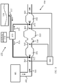
- the oxidising coating for example comprising precious metals, which in Euro VI-systems is located in the oxidation catalyst DOC, may according to one embodiment of the invention at least partly be implemented for example in a first slip-catalyst SC 1 , which is comprised in the first reduction catalyst device 331, wherein conditions for a sufficient NO 2 -based soot oxidation may be obtained.
- the catalytic coating for the first reduction catalyst device may, according to one embodiment, be selected to be robust in withstanding chemical poisoning, which may, over time, provide a more stable level for the ratio between nitrogen dioxide and nitrogen oxides NO 2 /NO x reaching the second reduction catalyst device.
- the supply of the first additive is controlled with the use of said first dosage device, based on a distribution of the ratio between nitrogen dioxide and nitrogen oxides NO 2 /NO x in the first reduction catalyst device.
- the present invention also has an advantage in that two cooperating dosage devices are used in combination for the dosage of a reductant, for example urea, upstream of the first and second reduction catalyst devices, which relieves and facilitates mixture and potential evaporation of the reductant, since the injection of the reductant is divided between two physically separate positions. This reduces the risk of the reductant cooling down the exhaust treatment system locally, which may potentially form deposits at the positions where the reductant is injected, or downstream of such positions.
- a reductant for example urea
- the relief of vaporisation of the reductant means that the exhaust back pressure may potentially be reduced, since the requirement for NO x -conversion per reduction step is reduced, so that the amount of reductant that must be vaporised is also reduced, since the injection of the reductant is divided between two positions, compared to the previous single dosage position. It is also possible, with the present invention, to shut off dosage in one dosage position, and then to remove potential precipitates that may arise, using heat. Accordingly, for example a larger dosage amount (a more ample dosage) may be allowed in the first dosage position for the first reduction catalyst device, since potential precipitates may be removed with heat at the same time as the emission requirements are met by the second reduction catalyst device during this time. This larger/more ample dosage may be viewed as a more aggressive dosage, providing dosage amounts closer to/above a dosage threshold value at which a risk of precipitates/crystallisations of additive arises.
- a non-limiting example may be that, if the single dosage device in the Euro VI-system had been optimised to provide a vaporisation and a distribution of the reductant providing a 98% NO x -conversion, the NO x -conversion of the two respective reduction catalyst devices in the exhaust treatment system according to the present invention may be reduced, for example to 60% and 95%, respectively.
- the amounts of reductant, which in this case have to be vaporised in the respective two positions become lower, and the allocations of reductant need not be as optimised in the system according to the invention as in the Euro VI-system.
- the two dosage positions used in the present invention thus facilitate that, overall, more additive may be supplied to the exhaust stream, than if only one dosage position had been used in the system. This means an improved performance may be provided.
- the present invention thus provides a removal of load for the mixing and the potential vaporisation.
- the double dosage positions mean, on the one hand, that the reductant is mixed and potentially vaporised in two positions, instead of in one position as in the Euro VI-system and, on the other hand, the double dosage positions mean that lower conversion levels, and thus a dosage with a less unfavourable ratio, may be used.
- the influence of the size of the conversion level and the ratio of the dosage is described in further detail below.
- the vaporisation is also improved, when the system according to the invention is used.
- the total amount of additive to be supplied to the exhaust stream is split in two physically separate dosage positions and, on the other hand, the system may be loaded more heavily than systems with only one dosage position.
- the system may be loaded more heavily since the dosage in the position where residue of additive potentially arises may, where needed, be reduced/closed with the system according to the invention, while criteria for the total emissions simultaneously may be met.
- the exhaust treatment system according to the present invention also provides for a robustness against errors in the dosage amounts of reductant.
- an NO x -sensor is placed between the two dosage devices in the exhaust treatment system. This means it is possible to correct a potential dosage error at the first dosage device, in connection with administration of a dose with the second dosage device.
- Table 1 below shows a non-limiting example of conversion levels and emissions, which are the result of a 10% dosage error for the reductant in a case with 10 g/kWh NO x .
- a 98% conversion of NO x is requested.
- a 60% conversion of NO x is requested for the first reduction catalyst device, and a 95% conversion of NO x is requested for the second reduction catalyst device.
- a system with one reduction step such as in the Euro VI-system, results in a 1.18 g/kWh emission.
- This embodiment may be implemented with a low level of added complexity, since an NO x -sensor, which is already present in today's Euro VI-system, may be used in connection with the correction.
- the NO x -sensor normally sits in the silencer inlet.
- the first reduction catalyst device and its first dosage in the present invention does not necessarily need to remove all nitrogen oxides NO x from the exhaust stream, the first reduction catalyst device, and its first dosage, may potentially cope without any measured information about nitrogen oxides NO x upstream of the first reduction catalyst device.
- This position i.e. the position at or upstream of the second reduction catalyst device, should therefore, according to one embodiment of the invention, suitably be equipped with a NO x -sensor.
- This NO x -sensor may thus, according to the embodiment of the invention, be placed downstream of the particulate filter, which is also a less aggressive environment from a chemical poisoning perspective, compared to the environment upstream of the particulate filter.
- an adaptation/calibration of several NO x -sensors in the exhaust treatment system may easily be carried out in the system according to the present invention, since the sensors may be subjected to the same NO x -level, at the same time as the emission levels may be kept at reasonable levels during the adaptation/calibration.
- the adaptation/calibration often entails that the emissions become too high during, and also partly after, the adaptation/calibration itself.
- the first and second reduction catalyst devices may be optimised individually, and with consideration of the entire exhaust treatment system's function, which may result in an overall very efficient purification of the exhausts.
- This individual optimisation may also be used to reduce one or several of the volumes taken up by the first and second reduction catalyst devices, so that a compact exhaust treatment system is obtained.
- the exhaust treatment system according to the invention theoretically requires a total volume for the first and second reduction catalyst devices, equalling the size required of the reduction catalyst device in the Euro VI-system, to provide a NO x -conversion representing 98% with only one reduction catalyst.
- the Euro VI-system's requirement regarding the high 98% conversion level means that a larger catalyst volume is required than catalyst volumes representing the sum of the lower conversion levels 60% and 95%, respectively, according to the present inventions requirement. This is due to the non-linear relationship between volume and conversion level.
- high conversion levels such as for example 98%, imperfections in the distribution of exhausts and/or reductant impact the requirement for catalyst volume to a greater extent.
- High conversion levels also require a larger catalyst volume, since the high conversion levels result in a greater deposition/cover level of reductant on the catalyst surface. There is a risk that such deposited reductant may then desorb at some exhaust conditions, i.e. a so-called ammonia slip may arise.
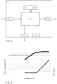
- FIG. 6 One example of the effect of the distribution of reductant and the effect of the increasing NH 3 -slip is illustrated in Figure 6 .
- the figure shows that the ratio, that is to say the gradient/derivative, for the conversion level (y axis to the left) decreases in relation to stoichiometry (x axis) at high conversion levels, that is to say that the curve for the conversion level planes out for high conversion levels, which among others is due to imperfections in the distribution of exhausts and/or reductant.
- the figure also shows that an increase of NH 3 -slip (y axis to the right) arises at higher conversion levels. At higher values than one (1) for the stoichiometry, more reductant is added than theoretically needed, which also increases the risk of NH 3 -slip.
- the present invention also facilitates, according to one embodiment, control of a ratio NO 2 /NO x , between the amount of nitrogen dioxide NO 2 and the amount of nitrogen oxides NO x , for the second reduction step, which means that the system may avoid excessively high values for this ratio, for example avoiding NO 2 /NO x > 50%, and that the system, by increasing the dosage, may increase the value for the ratio NO 2 /NO x when the value is too low, for example if NO 2 /NO x ⁇ 50%.
- the value for the ratio NO 2 /NO x may here, for example through the use of an embodiment of the present invention, be increased by reducing the level of nitrogen oxides NO x .
- the value for the ratio NO 2 /NO x for the first reduction step may be controlled, since the level of nitrogen oxides NO x at the first oxidation step is controlled by way of engine measures.
- the ratio NO 2 /NO x may assume lower values, for example after the system has aged for some time.
- the present invention thus provides for a possibility to counteract this characteristic which deteriorates over time and is negative to the system, resulting in values which are too low for the ratio NO 2 /NO x .
- the level of nitrogen dioxide NO 2 may thus be actively controlled, which is facilitated since the NO x -level may be adjusted upstream of the particulate filter 320.
- This control of the ratio NO 2 /NO x may, apart from advantages in catalytic performance, such as higher NO x -conversion, also provide for a possibility of specifically reducing emissions of nitrogen dioxide NO 2 , which result in a very poisonous and strong smelling emission. This may result in advantages at a potential future introduction of a separate regulatory requirement relating to nitrogen dioxide NO 2 , and facilitate a reduction of harmful emissions of nitrogen dioxide NO 2 .
- This may be compared with for example the Euro VI-system, in which the fraction of nitrogen dioxide NO 2 provided at the exhaust purification may not be impacted in the exhaust treatment system itself.
- the active control of the level of nitrogen dioxide NO 2 is facilitated at the use of the present invention, where the active control may be used to increase the level of nitrogen dioxide NO 2 in driving modes for which this is necessary. Accordingly, an exhaust treatment system may be selected/specified, which for example requires less precious metal and thus also is cheaper to manufacture.
- the fraction of the total conversion of nitrogen oxides NO x occurring via a rapid reaction path that is to say via a fast SCR, wherein the reduction occurs via reaction paths over both nitrogen oxide NO and nitrogen dioxide NO 2 , may be increased through active control of the level of nitrogen dioxide NO 2 , then the catalyst volume requirement described above may also be reduced.
- the first reduction catalyst device in the exhaust treatment system is active at a lower reduction temperature interval T red than the oxidation temperature interval T ox , which is required for the nitrogen dioxide based soot oxidation in the particulate filter DPF.
- the nitrogen dioxide based soot oxidation in the particulate filter DPF may occur at temperatures exceeding 275 °C.
- the reduction of nitrogen oxides NO x in the first reduction catalyst device does not significantly compete with the soot oxidation in the particulate filter DPF, since they are active within at least partly different temperature intervals T red ⁇ T ox .
- a well selected and optimised first reduction catalyst device may result in a significant conversion of nitrogen oxides NO x at approximately 200 °C, which means that this first reduction catalyst device does not need to compete with the particulate filter's soot oxidation performance.
- secondary emissions such as emissions of ammonia NH 3 and/or nitrous oxide (laughing gas) N 2 O may be reduced in relation to a given conversion level, and/or a given NO x -level.
- a catalyst for example an SC (Slip Catalyst), which may be comprised in the second reduction step if the emissions for certain jurisdictions must be reduced to very low levels, may have a certain selectivity against, for example, nitrous oxide N 2 O, which means that the reduction of the NO x -level through the use of the additional reduction step according to the present invention also shifts the resulting levels for nitrous oxide N 2 O downwards.
- the resulting levels for ammonia NH 3 may be shifted downwards in a similar way, when the present invention is used.
- a better fuel optimisation may be obtained for the vehicle, since there is thus potential to control the engine in a more fuel efficient manner, so that a higher efficiency for the engine is obtained.
- a performance gain and/or a reduced emission of carbon dioxide CO 2 may be obtained when the present invention is used.
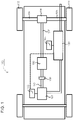
- FIG. 1 schematically shows an example vehicle 100, comprising an exhaust treatment system 150, which may be an exhaust treatment system 150 according to one embodiment of the present invention.
- the power-train comprises a combustion engine 101, which in a customary manner, via an output shaft 102 on the combustion engine 101, usually via a flywheel, is connected to a gearbox 103 via a clutch 106.
- the combustion engine 101 is controlled by the engine's control system via a control device 115.
- the clutch 106 and the gearbox 103 may be controlled by the vehicle's control system with the help of one or more applicable control devices (not shown).
- the vehicle's driveline may also be of another type, such as a type with a conventional automatic gearbox, of a type with a hybrid driveline, etc.
- An output shaft 107 from the gearbox 103 drives the wheels 113, 114 via a final drive 108, such as e.g. a customary differential, and the drive shafts 104, 105 connected to the said final drive 108.
- a final drive 108 such as e.g. a customary differential
- the vehicle 100 also comprises an exhaust treatment system/exhaust purification system 150 for treatment/purification of exhaust emissions resulting from combustion in the combustion chamber of the combustion engine 101, which may consist of cylinders.
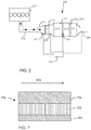
- FIG. 2 shows a prior art exhaust treatment system 250, which may illustrate the above mentioned Euro VI-system, and which is connected to a combustion engine 201 via an exhaust conduit 202, wherein the exhausts generated at combustion, that is to say the exhaust stream 203, is indicated with arrows.
- the exhaust stream 203 is led to a diesel particulate filter (DPF) 220, via a diesel oxidation catalyst (DOC) 210.
- DPF diesel particulate filter
- DOC diesel oxidation catalyst
- soot particles are formed, and the particulate filter 220 is used to catch these soot particles.
- the exhaust stream 203 is here led through a filter structure, where soot particles are caught from the exhaust stream 203 passing through, and are stored in the particulate filter 220.
- the oxidation catalyst DOC 210 has several functions and is normally used primarily to oxidise, during the exhaust treatment, remaining hydrocarbons C x H y (also referred to as HC) and carbon monoxide CO in the exhaust stream 203 into carbon dioxide CO 2 and water H 2 O.
- the oxidation catalyst DOC 210 may also oxidise a large fraction of the nitrogen monoxides NO occurring in the exhaust stream into nitrogen dioxide NO 2 .
- the oxidation of nitrogen monoxide NO into nitrogen dioxide NO 2 is important to the nitrogen dioxide based soot oxidation in the filter, and is also advantageous at a potential subsequent reduction of nitrogen oxides NO x .
- the exhaust treatment system 250 further comprises an SCR (Selective Catalytic Reduction) catalyst 230, downstream of the particulate filter DPF 220.
- SCR catalysts use ammonia NH 3 , or a composition from which ammonia may be generated/formed, e.g. urea, as an additive for the reduction of nitrogen oxides NO x in the exhaust stream.
- the reaction rate of this reduction is impacted, however, by the ratio between nitrogen monoxide NO and nitrogen dioxide NO 2 in the exhaust stream, so that the reductive reaction is impacted in a positive direction by the previous oxidation of NO into NO 2 in the oxidation catalyst DOC. This applies up to a value representing approximately 50% of the molar ratio NO 2 /NO x . For higher fractions of the molar ratio NO 2 /NO x , that is to say for values exceeding 50%, the reaction speed is impacted in a strongly negative manner.
- the SCR-catalyst 230 requires additives to reduce the concentration of a compound, such as for example nitrogen oxides NO x , in the exhaust stream 203.
- a compound such as for example nitrogen oxides NO x
- Such additive is injected into the exhaust stream upstream of the SCR-catalyst 230 (not shown in figure 2 ).
- Such additive is often ammonia and/or urea based, or consists of a substance from which ammonia may be extracted or released, and may for example consist of AdBlue, which basically consists of urea mixed with water.
- Urea forms ammonia at heating (thermolysis) and at heterogeneous catalysis on an oxidizing surface (hydrolysis), which surface may, for example, consist of titanium dioxide TiO2, within the SCR-catalyst.
- the exhaust treatment system may also comprise a separate hydrolysis catalyst.
- the exhaust treatment system 250 is also equipped with a slip-catalyst (SC), which is arranged to oxidise a surplus of ammonia, which may remain after the SCR-catalyst 230, and/or to assist the SCR-catalyst with additional NO x -reduction. Accordingly, the slip-catalyst SC may provide a potential for improving the system's total conversion/reduction of NOx.
- SC slip-catalyst
- the exhaust treatment system 250 is also equipped with one or several sensors, such as one or several NO x and/or temperature sensors 261, 262, 263, 264 for the determination of nitrogen oxides and/or temperatures in the exhaust treatment system.
- sensors such as one or several NO x and/or temperature sensors 261, 262, 263, 264 for the determination of nitrogen oxides and/or temperatures in the exhaust treatment system.
- the prior art exhaust treatment system shown in Figure 2 that is to say the Euro VI-system, has a problem in that catalysts are efficient heat exchangers, which jointly with the rest of the exhaust system, comprising for example the exhaust conduit 202, as well as material and space for silencing and various connections, has a substantial thermal mass/inertia.
- the catalyst temperature is below its optimal operating temperature, which may for example be approximately 300 °C, and at a throttle from low exhaust temperatures, which may for example occur when light city driving transitions into motorway driving, or after idling and power take-off, the exhaust temperature is filtered by this large thermal mass.
- the function, and therefore the efficiency of the reduction is impacted by for example nitrogen oxides NO x in the SCR-catalyst 230, which may entail that a poor exhaust purification is provided by the system shown in Figure 2 .
- a so-called fast SCR may be used, for controlling reduction, so that it occurs to as great an extent as possible via reaction paths over both nitrogen oxide NO and nitrogen dioxide NO 2 .
- the reaction uses equal parts of nitrogen monoxide NO and nitrogen dioxide NO 2 , which means that an optimal value of the molar ration NO 2 /NO x is near 50%.
- This higher fraction of nitrogen dioxides NO 2 results in a greater volume requirement for the SCR-catalyst, and/or in a limitation of the amount of nitrogen oxides released from the engine, and accordingly in a poorer fuel efficiency for the vehicle. Additionally, there is a risk that the higher fraction of nitrogen dioxides NO 2 also results in emissions of laughing gas N 2 O. These risks of a non-advantageous fraction of nitrogen dioxide NO 2 arising also exist due to the system's ageing. For example, the ratio NO 2 /NO x may assume lower values when the system has aged, which may entail that a catalyst specification, which results in too high fractions of NO 2 /NO x in a non-aged state, must be used to compensate for ageing.
- a poor control robustness against dosage errors regarding the amount of reductant and/or a poor control robustness against a sensor error may also constitute a problem for the exhaust treatment system at high NO x -conversion levels.
- the exhaust system must consist of a close connected SCR-catalyst (ccSCR), which shall be connected near, less than 1 metre away from, the engine's or the turbo's exhaust outlet, followed by an SCRT-system downstream.
- ccSCR close connected SCR-catalyst
- SCRT-system is defined by the authors of US2005/0069476 as a prior art system in the direction of the exhaust stream, comprising a DOC-catalyst, a DPF-filter, a urea dosage device, and an SCR-catalyst.
- the exhaust treatment system described in US2005/0069476 consists of the following sequential, separate components in the direction of the exhaust stream's flow: the close connected ccSCR-catalyst, the DOC-catalyst, the DPF-filter, and the SCR-catalyst; ccSCR-DOC-DPF-SCR.
- FIG. 3 schematically shows an exhaust treatment system 350, which is connected via an exhaust pipe 302 to a combustion engine 301.
- Exhausts generated at combustion in the engine 301 and the exhaust stream 303 (indicated with arrows) are led to an oxidation catalyst DOC 310, which is arranged to oxidise nitrogen compounds, carbon compounds and/or hydrocarbon compounds in the exhaust stream 303 in the exhaust treatment system 350.
- DOC 310 oxidise nitrogen compounds, carbon compounds and/or hydrocarbon compounds in the exhaust stream 303 in the exhaust treatment system 350.
- a first dosage device 371 which is arranged downstream of the oxidation catalyst DOC 310, and is arranged to supply a first additive in the exhaust stream 303.
- a first reduction catalyst device 331 is arranged downstream of the first dosage device 371.
- the first reduction catalyst device 331 is arranged to reduce nitrogen oxides NO x in the exhaust stream 303, through the use of the first additive added to the exhaust stream by the first dosage device 331.
- the first reduction catalyst device 331 uses an additive, for example ammonia NH 3 or urea, from which ammonia may be generated/formed/released, for the reduction of nitrogen oxides NO x in the exhaust stream 303.
- This additive may for example consist of the above mentioned AdBlue.
- the first reduction catalyst device 331 is also arranged to generate heat with at least one exothermal reaction with the exhaust stream 303 through the use of at least one oxidising coating, where the generated heat enables regeneration of one or more sulphur contaminated components in the exhaust treatment system 350, including the first reduction catalyst device 331, a particulate filter 320 and/or a silencer.
- a first hydrolysis catalyst which may consist of substantially any suitable hydrolysis coating, and/or a first mixer, may be arranged in connection with the first dosage device 371.
- the first hydrolysis catalyst, and/or the first mixer are then used to increase the speed of the decomposition of urea into ammonia, and/or to mix the additive with the emissions, and/or to vaporise the additive.
- the increased fraction of nitrogen dioxide NO 2 in the exhaust stream 303 which is obtained with the use of the oxidation catalyst placed upstream of the first reduction catalyst device DOC 310, means that a larger fraction of the total conversion of nitrogen oxides NO x occurs via the fast reaction path, that is to say via fast SCR, when the reduction occurs via reaction paths over both nitrogen oxide and nitrogen dioxide NO 2 .
- the oxidation catalyst 310 fitted upstream of the first reduction catalyst device, also generates heat at oxidation of potential hydrocarbon compounds in the exhaust stream, which means that this heat may be used, for example, to optimise the NO x -reduction.
- the exhaust treatment system 350 may, according to one embodiment, comprise at least one external injector, which supplies the oxidation catalyst, and/or a selective catalytic reduction catalyst having an oxidising coating at its outlet SCR 1_komb , with hydrocarbons HC.
- the engine may in this case also be seen as an injector, supplying the oxidation catalyst and/or SCR 1_komb with hydrocarbons HC, wherein the hydrocarbons HC may be used to generate heat.
- the present invention facilitates, according to one embodiment, a control of a ratio NO 2 /NO x , between the amount of nitrogen dioxide NO 2 and the amount of nitrogen oxides NO x , for the first reduction step, by way of adjusting, with engine- and/or combustion measures, the level/amount of nitrogen oxides NO x reaching the oxidation catalyst 310.
- a ratio NO 2_1 NO x_1 between the first amount of nitrogen dioxide NO 2_1 and the first amount of nitrogen oxides NO x_1 , reaching the first reduction catalyst device 331.
- the adjustment is achieved by way of an active control with engine and/or combustion measures, of an amount of nitrogen oxides NO x_DOC that is emitted from the engine and subsequently reaches the oxidation catalyst 310.
- an active control is thereby obtained also of the first amount of nitrogen oxides NO x_1 reaching the first reduction catalyst device 331, since the level of the first amount of nitrogen oxides NO x_1 depends on the amount of nitrogen oxides NO x_DOC emitted from the engine.
- the present invention also facilitates, according to one embodiment, a control of a ratio NO 2 /NO x , between the amount of nitrogen dioxide NO 2 and the amount of nitrogen oxides NO x , for the second reduction step, by adapting the dosage of additive at the first reduction catalyst device.
- the exhaust treatment system 350 comprises a particulate filter 320 downstream of the first reduction catalyst device 331.
- the particulate filter 320 is arranged to catch and oxidise soot particles.
- the exhaust stream 303 is here led through the filter structure of the particulate filter, where soot particles are caught in the filter structure from the exhaust stream 303 passing through, and are stored and oxidised in the particulate filter.
- the particulate filter 320 is arranged so that the particulate filter 320 is the first exhaust treatment system component which the exhaust stream 303 reaches, after it has passed the first reduction catalyst device 331.
- the particulate filter 320 according to the embodiment is connected downstream of the reduction catalyst device 331, without any intermediate exhaust treatment system components, except potential conduit connections between the reduction catalyst device 331 and the particulate filter 320.
- the first reduction catalyst device 331 may comprise a first selective catalytic reduction catalyst device SCR 1 , and/or a first slip-catalyst SC 1 , and/or an additional first slip-catalyst SC 1b .
- SCR 1 selective catalytic reduction catalyst device
- SC 1 slip-catalyst SC 1
- SC 1b additional first slip-catalyst SC 1b .
- One advantage with connecting the particulate filter 320 downstream of the reduction catalyst device 331, without any intermediate exhaust treatment system components, apart from potential pipe connections, is that the number of substrates in the exhaust treatment system 350 is smaller than if, for example, the oxidation catalyst DOC had been arranged between the particulate filter 320 and the reduction catalyst device 331. Fewer substrates results in a possibility for a more compact exhaust treatment system 350 with lower back pressure, which is simpler and cheaper to manufacture and/or fit.
- the system according to the embodiment of the present invention relates to cleaning the filter of soot with the NO 2 -based passive regeneration/oxidation.
- the present invention may also advantageously be used in connection with active regeneration of the filter, for example by way of using an injector, which supplies fuel upstream of the filter.
- the exhaust treatment system according to the invention has one advantage in that the first reduction catalyst device may itself cope with a certain NO x -conversion, while, due to the regeneration, the second reduction catalyst device, arranged downstream of the filter, experiences such a high temperature that it has difficulties in achieving a high conversion level.
- the engine's injection system at a regeneration of the particulate filter DPF, or of another exhaust treatment component, such as for example the first reduction catalyst device, it will be possible to use the oxidation catalyst to generate necessary heat.
- the first reduction catalyst device will also at least partly assist the particulate filter DPF with oxidising the fuel into primarily carbon monoxide CO.
- the regeneration of the particulate filter DPF is simplified, compared to exhaust treatment systems that do not have a first reduction catalyst device and an oxidation catalyst DOC according to the present invention.
- the exhaust treatment system 350 Downstream of the particulate filter DPF 320, the exhaust treatment system 350 is equipped with a second dosage device 372, which is arranged to supply a second additive to the exhaust stream 303, where such second additive comprises ammonia NH 3 , or a substance, for example AdBlue, from which ammonia may be generated/formed/released, as described above.
- the second additive may here consist of the same additive as the above mentioned first additive, that is to say that the first and second additives are of the same type and may possibly also come from the same tank.
- the first and second additives may also be of different types and may come from different tanks.
- a second hydrolysis catalyst and/or a second mixer may also be arranged in connection with the second dosage device 372.
- the function and embodiment of the second hydrolysis catalyst and/or the second mixer correspond to those described above for the first hydrolysis catalyst and the first mixer.
- the exhaust treatment system 350 also comprises a second reduction catalyst device 332, which is arranged downstream of the second dosage device 372.
- the second reduction catalyst device 332 is arranged to reduce nitrogen oxides NO x in the exhaust stream 303 through use of the second additive and, if the first additive remains in the exhaust stream 303 when this reaches the second reduction catalyst device 332, also through use of the first additive.
- the exhaust treatment system 350 may also be equipped with one or several sensors, such as one or several NO x -sensors 361, 363, 364, 365, and/or one or several temperature sensors 362, 363, 365, which are arranged for the determination of NO x -concentrations and temperatures in the exhaust treatment system 350, respectively.
- a robustness against errors in administered doses of reductant may be achieved by way of an embodiment of the invention, wherein an NO x -sensor 363 is placed between the two dosage devices 371, 372, and preferably between the particulate filter 320 and the second dosage device 372, in the exhaust treatment system 350. This makes it possible, by way of the second dosage device 372, to correct a potential dosage error, which has created unforeseen emission levels downstream of the first reduction device 371, and/or the particulate filter 320.
- This placement of NO x -sensor 363 between the two dosage devices 371, 372 and, preferably, between the particulate filter DPF 320 and the second dosage device 372, also makes it possible to correct the amount of additive administered by the second dosage device 372 for nitrogen oxides NO x , which may be created over the particulate filter DPF 320 from excess remainders of additive from the dosage carried out by the first dosage device 371.
- the NO x -sensor 364 downstream of the second reduction catalyst device 332 may be used at feedback of dosage of additive.
- both the first reduction catalyst device 331 and the second reduction catalyst device 332 may be optimised with respect to a selection of catalyst characteristics for the reduction of nitrogen oxides NO x , and/or with respect to volumes for the first 331 and second 332 reduction catalyst devices, respectively.
- the particulate filter 320 is used to the advantage of the function, by taking into account its thermal mass impacts the temperature of the second reduction catalyst.
- the thermal inertia of the particulate filter 320, the first reduction catalyst device 331 and the second reduction catalyst device 332, respectively, may be optimised with respect to the specific temperature function each will experience. Since the optimised first 331 and second 332 reduction catalyst devices are set up to purify the exhausts in cooperation, according to the present invention, the exhaust treatment system 350, or at least a part of its components, may be made compact. Since the space allocated to the exhaust treatment system 350 for example in a vehicle is limited, it is a great advantage to provide a compact exhaust treatment system, through a high usage level of the catalysts used according to the present invention. Such high usage level and the associated smaller volume requirement, also provide a possibility for a reduced back pressure, and accordingly also a lower fuel consumption.
- the present invention provides for an exhaust treatment system 350, which efficiently reduces the amount of nitrogen oxides NO x in the exhaust stream in substantially all driving modes, comprising especially cold starts and throttle, that is to say increased requested torque, from a low exhaust temperature and a load deduction, that is to say from a reduced requested torque.
- the exhaust treatment system 350 according to the present invention is suitable in substantially all driving modes, which give rise to a transient temperature evolution in the exhaust treatment.
- a driving mode may consist of city driving comprising many starts and decelerations.
- the problems with prior art technology which are related to a too high fraction of nitrogen dioxides NO 2 , may be resolved at least partly with the use of the present invention, since two reduction catalyst devices 371, 372 are comprised in the exhaust treatment system 350.
- the problem may be resolved by way of combining the present invention with the knowledge that the amount of nitrogen oxides NO x controls, how large a fraction of nitrogen dioxides NO 2 is obtained downstream of a filter/substrate coated with a catalytically oxidising coating, meaning that the amount of nitrogen oxides NO x may be used to control the value of the ratio NO 2 /NO x .
- the first reduction catalyst device 331 in the exhaust treatment system 350 is, according to one embodiment, active at a lower reductant temperature interval T red than the oxidation temperature interval T ox , at which the nitrogen dioxide based soot oxidation, that is to say the oxidation of incompletely oxidised carbon compounds in the particulate filter 320, is active.
- the temperature for a so-called “light-off” for soot oxidation in the particulate filter 320 is higher than the "light-off” for the reduction of nitrogen oxides NO x in the first reduction catalyst device 331.
- the reduction of nitrogen oxides NO x in the first reduction catalyst device 331 does not necessarily compete with the soot oxidation in the particulate filter 320, since they are active within at least partly different temperature intervals; T red ⁇ T ox .
- the exhaust treatment system sometimes requests that the engine generate heat for the exhaust treatment system, to be able to achieve a sufficient efficiency with respect to exhaust purification. This heat generation is in this case achieved at the expense of the engine's total efficiency relating to fuel consumption, which decreases.
- One advantageous characteristic of the exhaust treatment system according to the present invention is that the first reduction catalyst device upstream of the filter may be made to react faster to such generated heat, than what would have been possible for example with the Euro VI-system. Therefore, less fuel is consumed overall with the use of the present invention.
- the engine is controlled so that it generates such heat with a scope making the first reduction catalyst device reach a certain given temperature/performance. Therefore, an efficient exhaust purification may be obtained, since the first reduction catalyst device may operate at a favourable temperature, while unnecessary heating, and therefore fuel inefficiency, is avoided.
- the first reduction catalyst device 331 according to the present invention does not need to be closely connected to the engine and/or the turbo.
- the fact that the first reduction catalyst device 331 according to the present invention may be fitted further away from the engine and/or the turbo, and for example may be located in the silencer, has an advantage in that a longer mixing distance for additive may be obtained in the exhaust stream between the engine, and/or the turbo and the first reduction catalyst device 331. This means that an improved utilisation is obtained for the first reduction catalyst device 331.
- the many advantages mentioned in this document associated with the potential reduction of nitrogen oxides NO x both upstream and downstream of the thermally inertial filter are achieved.
- An additional advantage of the present invention may be attributed to the fact that the oxidation catalyst DOC 310, and the second reduction catalyst device 332, are situated/placed in thermally different positions. This entails, for example, that at a throttle the oxidation catalyst DOC 310 and the first reduction catalyst device 331 will achieve a higher exhaust temperature, before the second reduction catalyst device 332 reaches a higher temperature.
- the first reduction catalyst device 331 then provides, as mentioned above, for a possible reduction of nitrogen oxides NO x , before the second reduction catalyst device 332.
- the layout/configuration of the exhaust treatment system 350 will also mean that the second reduction catalyst device 332 has greater possibilities of carrying out the reduction according to fast SCR, since the oxidation catalyst DOC 310 may begin to convert nitrogen monoxide NO into nitrogen dioxide NO 2 early.
- the critical throttle when there is a shortage of high exhaust temperatures, with the use of the present invention a more favourable environment is obtained for the first, and/or the second reduction catalyst device, via a more advantageous ratio between nitrogen dioxide and nitrogen oxides NO 2 /NO x , than what would have been the case if the oxidation catalyst DOC 310 had not been included in the exhaust treatment system 350.
- the first reduction catalyst device 331 consists of one of:
- slip-catalyst SC is used generally to denote a catalyst, which is arranged to oxidise additive in the exhaust stream 303, and/or which is arranged so that it is able to reduce residual nitrogen oxides NO x in the exhaust stream 303.
- a slip catalyst SC is arranged primarily to reduce nitrogen oxides NO x , and secondarily to oxidise a residue of additive, that is to say that the slip-catalyst SC is a multifunctional slip-catalyst.
- the multifunctional slip-catalyst SC may take care of slip-residues of both additive and nitrogen oxides NO x .
- slip-catalyst SC being an extended ammonia slip-catalyst ASC, which is set up to reduce nitrogen oxides NO x in the exhaust stream 303, so that a general/multifunctional slip-catalyst SC is obtained, which takes care of several types of slip, meaning it takes care of residues of both additive and nitrogen oxides NO x .
- first slip-catalyst SC 1 and/or the additional first slip-catalyst SC 1b , which may be comprised in the first reduction catalyst device 331, may be used in order to generate heat via exothermal reactions with the exhaust stream 303, which heat may be forwarded to the particulate filter DPF, and may be used to increase the temperature of the particulate filter DPF.
- At least the following reactions may for example be carried out in a multifunctional slip-catalyst SC, which both reduces nitrogen oxides NO x and oxidises residues of additive: NH 3 + O 2 ⁇ N 2 ; and NO x + NH 3 ⁇ N 2 + H 2 0 .
- the reaction according to equation 1 results in an oxidation of residue of additive, comprising ammonia.
- the reaction according to equation 2 results in a reduction of nitrogen oxides NO x .
- the additive may here be oxidised, as well as residue of ammonia NH 3 , isocyanic acid HNCO, urea or similar may be oxidised.
- residues of the additive that is ammonia NH3, HNCO, urea or similar, may here also be used to oxidise the nitrogen oxides NOx.
- the first reduction catalyst device 33 that is to say the first slip-catalyst SC 1 , the first reduction catalyst SCR 1 , and/or the additional first slip-catalyst SC 1b , may be used for oxidation of hydrocarbons HC and/or carbon monoxide CO, which occur naturally in the exhaust stream.
- the oxidation of hydrocarbons in the first reduction catalyst device 331 may also comprise at least one exothermal reaction, that is to say a reaction which generates heat, so that a temperature increase ensues for the first reduction catalyst device 331, and/or for components following downstream, such as the particulate filter DPF 320 and/or a silencer, in the exhaust treatment system 350.
- Such temperature increase may be used at soot oxidation in the particulate filter DPF 320, and/or to clean the silencer of by-products, such as for example urea. Through this at least one exothermal reaction, oxidation of hydrocarbons HC is also facilitated in the first reduction catalyst device 331.
- the slip-catalyst may according to one embodiment comprise one or several substances comprised in platinum metals (PGM; Platinum Group Metals), that is to say one or several of iridium, osmium, palladium, platinum, rhodium and ruthenium.
- PGM Platinum Group Metals
- the slip-catalyst may also comprise one or several other substances, which give the slip-catalyst similar characteristics as platinum group metals.
- the slip-catalyst may also comprise an NO x -reducing coating, where the coating may for example comprise Cu- or Fe-Zeolite or vanadium. Zeolite may here be activated with an active metal, such as for example copper (Cu) or iron (Fe).
- first 331 and second 332 reduction catalyst device these catalytic characteristics may be selected based on the environment to which it is exposed, or will be exposed to. Additionally, the catalytic characteristics for the first 331 and second 332 reduction catalyst device may be adapted so that they may be allowed to operate in symbiosis with each other.
- the first 331 and second 332 reduction catalyst device may also comprise one or several materials, providing the catalytic characteristic. For example, transition metals such as vanadium and/or tungsten may be used, for example in a catalyst comprising V 2 O 5 /WO 3 /TiO 2 . Metals such as iron and/or copper may also be comprised in the first 331 and/or second 332 reduction catalyst device, for example in a Zeolite-based catalyst.
- the exhaust treatment system 350 which is schematically illustrated in Figure 3 , may, according to different embodiments accordingly have a number of different structures/configurations, which may be summarised as below, and where the respective units DOC, SCR 1 , SCR 1_komb , SCR 2 , DPF, SC 1 , SC 1b SC 2 have the respective characteristics described in this entire document.
- the catalytically oxidising coating of the first slip-catalyst SC 1 , the additional first slip-catalyst SC 1b , the first selective catalytic reduction catalyst SCR 1 , the first selective catalytic reduction catalyst SCR 1_komb , combined with a purely oxidising coating in its outlet part on the same substrate, the second selective catalytic reduction catalyst SCR 2 , and/or the second slip-catalyst SC 2 may be adapted according to these characteristics, to oxidise nitrogen oxide NO, and to oxidise incompletely oxidised carbon compounds. Incompletely oxidised carbon compounds may for example consist of fuel residue created through the engine's injection system.
- the exhaust treatment system has the structure DOC-SCR 1 -DPF-SCR 2 .
- the exhaust treatment system 350 comprises an oxidation catalyst DOC, followed downstream by a first selective catalytic reduction catalyst SCR 1 , which is arranged to be able to generate heat, followed downstream by a particulate filter DPF, followed downstream by a second selective catalytic reduction catalyst SCR 2 .
- a symbiotic usage in the exhaust treatment system 350 of both the first selectively catalytic reduction catalyst SCR 1 , jointly with the second selectively catalytic reduction catalyst SCR 2 may facilitate the omission of a second slip-catalyst SC 2 in the exhaust treatment system 350 for certain applications, for example at limited NO x -levels, which result in limited conversion level requirements.
- This is an advantage, for example compared with the above mentioned Euro VI-system, in which a slip-catalyst is, in practice, required. Since an SCR-catalyst is typically cheaper than an SC-catalyst, thanks to this embodiment of the invention, the manufacturing cost may be reduced by omitting the second slip-catalyst SC 2 .
- the first selective catalytic reduction catalyst SCR 1 may here be used with the objective of generating heat, for example by oxidation of hydrocarbons HC in the exhaust stream, which enables regeneration of sulphur contaminated components, such as the catalyst, and/or components arranged downstream of the latter. At the regeneration of the sulphur contaminated components, the amount of sulphur intercalated in the components is reduced.
- the first selective catalytic reduction catalyst SCR 1 may be used to generate heat through exothermal reactions with the exhaust stream 303, which heat may also be conveyed to the particulate filter DPF, and may be used there to increase the temperature of the particulate filter DPF.
- the particulate filter may, thanks to this at least one exothermal reaction with the exhaust stream 303, be heated, which may be used to obtain a more efficient soot oxidation in the particulate filter DPF, and may also be used at the regeneration of the particulate filter DPF.
- the increased fraction of nitrogen dioxide NO 2 in the exhaust stream 303 which is obtained with the use of the oxidation catalyst, means that a larger fraction of the total conversion of nitrogen oxides NO x occurs via the fast reaction path, that is to say via fast SCR, when the reduction occurs via reaction paths over both nitrogen oxide and nitrogen dioxide NO 2 .
- the oxidation catalyst DOC fitted upstream of the first reduction catalyst device, also generates heat at oxidation of potential hydrocarbon compounds in the exhaust stream, which means that this heat may be used, for example, to optimise the NO x -reduction.
- the exhaust treatment system has the structure DOC-SCR 1 -SC 1 -DPF-SCR 2 . That is to say, the exhaust treatment system 350 comprises an oxidation catalyst DOC, followed downstream by a first selective catalytic reduction catalyst SCR 1 , followed downstream by a first slip-catalyst SC 1 , followed downstream by a particulate filter DPF, followed downstream by a second selective catalytic reduction catalyst SCR 2 .
- the use of both the first selectively catalytic reduction catalyst SCR 1 and the second selectively catalytic reduction catalyst SCR 2 in the exhaust treatment system 350 facilitates the omission of a second slip-catalyst SC 2 in the exhaust treatment system 350 for some applications, which reduces the manufacturing cost for the vehicle.
- the use of the first slip-catalyst SC 1 facilitates a greater load, and therefore a better use of the first selective catalytic reduction catalyst SCR 1 , and it also facilitates a reduction of the starting temperature (the "light off"- temperature) for the NO x -reduction.
- the first reduction catalyst device 331 here comprises a slip-catalyst SC 1 that is multifunctional, and therefore reduces nitrogen oxides NO x by using residues of the additive, and also oxidising the residues of the additive (as described above). This entails a number of advantages for the exhaust treatment system.
- the first slip-catalyst SC 1 may here be used in symbiosis with the first reduction catalyst SCR 1 , so that the activity of the first slip-catalyst SC 1 , with respect to reduction of nitrogen oxides NO x and oxidation of residues of additive, as well as the slip-catalyst's SC 1 deposition characteristics for the reductant, constitute a complement to the function of the first reduction catalyst SCR 1 .
- the combination of these characteristics for the first reduction catalyst device 331, comprising the first reduction catalyst SCR 1 and the first slip-catalyst SC 1 means that a higher conversion level may be obtained over the first reduction catalyst device 331.
- first slip-catalyst SC 1 in the first reduction catalyst device 331 results in conditions making it possible to avoid that a non-selective oxidation of reductant occurs in components, placed downstream of the first reduction catalyst device 331 in the exhaust treatment system, which may potentially comprise platinum metals.
- the first selective catalytic reduction catalyst SCR 1 and/or the first slip-catalyst SC 1 , may be used with the objective of generating heat, for example through oxidation of hydrocarbons HC in the exhaust stream, which enables regeneration of sulphur contaminated components, such as the catalyst and/or components arranged downstream of the latter. At the regeneration of the sulphur contaminated components, the amount of sulphur intercalated in the components is reduced.
- the first selective catalytic reduction catalyst SCR 1 , and/or the first slip-catalyst SC 1 , comprised in the first reduction catalyst device 331, may be used in order to generate heat via exothermal reactions with the exhaust stream 303, which heat may be conveyed to the particulate filter DPF, and may be used there to increase the temperature of the particulate filter DPF.
- the particulate filter may, thanks to this at least one exothermal reaction with the exhaust stream 303, be heated, which may be used to obtain a more efficient soot oxidation in the particulate filter DPF, and may also be used at the regeneration of the particulate filter DPF.
- the increased fraction of nitrogen dioxide NO 2 in the exhaust stream 303 which is obtained with the use of the oxidation catalyst, means that a larger fraction of the total conversion of nitrogen oxides NO x occurs via the fast reaction path, that is to say via fast SCR, when the reduction occurs via reaction paths over both nitrogen oxide and nitrogen dioxide NO 2 .
- the oxidation catalyst DOC fitted upstream of the first reduction catalyst device, also generates heat at oxidation of potential hydrocarbon compounds in the exhaust stream, which means that this heat may be used, for example, to optimise the NO x -reduction.
- the exhaust treatment system has the structure DOC-SCR 1 -DPF-SCR 2 -SC 2 . That is to say, the exhaust treatment system 350 comprises an oxidation catalyst, followed downstream by a first selective catalytic reduction catalyst SCR 1 , followed downstream by a particulate filter DPF, followed downstream by a second selective catalytic reduction catalyst SCR 2 , followed downstream by a second slip-catalyst SC 2 .
- This exhaust treatment system 350 facilitates emission levels for nitrogen oxides NO x close to zero, since the second reduction catalyst SCR 2 may be heavily loaded, for example by increased dosage of the second additive, since it is followed downstream by the second slip-catalyst SC 2 .
- the use of the second slip-catalyst SC 2 results in additionally improved performance for the system, since additional slip may be taken care of by the second slip-catalyst SC 2 .
- the first selective catalytic reduction catalyst SCR 1 may be used with the objective of generating heat, for example by oxidation of hydrocarbons HC in the exhaust stream, which enables regeneration of sulphur contaminated components, such as the catalyst, and/or components arranged downstream of the latter. At the regeneration of the sulphur contaminated components, the amount of sulphur intercalated in the components is reduced.
- the first selective catalytic reduction catalyst SCR 1 may be used to generate heat through exothermal reactions with the exhaust stream 303, which heat may also be conveyed to the particulate filter DPF, and may be used there to increase the temperature of the particulate filter DPF.
- the particulate filter may, thanks to this at least one exothermal reaction with the exhaust stream 303, be heated, which may be used to obtain a more efficient soot oxidation in the particulate filter DPF, and may also be used at the regeneration of the particulate filter DPF.
- the increased fraction of nitrogen dioxide NO 2 in the exhaust stream 303 which is obtained with the use of the oxidation catalyst, means that a larger fraction of the total conversion of nitrogen oxides NO x occurs via the fast reaction path, that is to say via fast SCR, when the reduction occurs via reaction paths over both nitrogen oxide and nitrogen dioxide NO 2 .
- the oxidation catalyst DOC fitted upstream of the first reduction catalyst device, also generates heat at oxidation of potential hydrocarbon compounds in the exhaust stream, which means that this heat may be used, for example, to optimise the NO x -reduction.
- the exhaust treatment system has the structure DOC- SCR 1 -SC 1 -DPF-SCR 2 -SC 2 . That is to say, the exhaust treatment system 350 comprises an oxidation catalyst, followed downstream by a first selective catalytic reduction catalyst SCR 1 , followed downstream by first slip-catalyst SC 1 , followed downstream by a particulate filter DPF, followed downstream by a second selective catalytic reduction catalyst SCR 2 , followed downstream by a second slip-catalyst SC 2 .
- This exhaust treatment system 350 facilitates emission levels for nitrogen oxides NO x close to zero, since the second reduction catalyst SCR 2 may be made to work hard, for example by increased dosage of the second additive, since it is followed downstream by the second slip-catalyst SC 2 .
- the use of the second slip-catalyst SC 2 results in additionally improved performance for the system, since additional slip may be taken care of by the second slip-catalyst SC 2 .
- the use of the first slip-catalyst SC 1 also facilitates a reduction of the starting temperature (the "light-off"-temperature) for the NO x -reduction, and may also result in a greater load, and thus an improved utilisation of the first selective catalytic reduction catalyst SCR 1 .
- the first reduction catalyst device 331 herein comprises an above described slip-catalyst SC 1 , which is multifunctional, and therefore reduces nitrogen oxides NO x through the use of residues of additive, and also oxidises the residues of the additive (as described above). This entails a number of advantages for the exhaust treatment system.
- the first slip-catalyst SC 1 may here be used in symbiosis with the first reduction catalyst SCR 1 , so that the activity of the first slip-catalyst SC 1 , with respect to reduction of nitrogen oxides NO x and oxidation of residues of additive, as well as the slip-catalyst's SC 1 deposition characteristics for the reductant, constitute a complement to the function of the first reduction catalyst SCR 1 .
- the combination of these characteristics for the first reduction catalyst device 331, comprising the first reduction catalyst SCR 1 and the first slip-catalyst SC 1 means that a higher conversion level may be obtained over the first reduction catalyst device 331.
- first slip-catalyst SC 1 in the first reduction catalyst device 331 results in conditions making it possible to avoid that a non-selective oxidation of reductant occurs in components, placed downstream of the first reduction catalyst device 331 in the exhaust treatment system, which may potentially comprise platinum metals.
- the first selective catalytic reduction catalyst SCR 1 and/or the first slip-catalyst SC 1 , may be used with the objective of generating heat, for example through oxidation of hydrocarbons HC in the exhaust stream, which enables regeneration of sulphur contaminated components, such as the catalyst and/or components arranged downstream of the latter. At the regeneration of the sulphur contaminated components, the amount of sulphur intercalated in the components is reduced.
- the first selective catalytic reduction catalyst SCR 1 , and/or the first slip-catalyst SC 1 , comprised in the first reduction catalyst device 331, may be used in order to generate heat via exothermal reactions with the exhaust stream 303, which heat may be conveyed to the particulate filter DPF, and may be used there to increase the temperature of the particulate filter DPF.
- the particulate filter may be heated, because the first selective catalytic reduction catalyst SCR 1 , and/or the first slip-catalyst SC 1 , creates at least one exothermal reaction with the exhaust stream 303, which is used to obtain a more efficient soot oxidation in the particulate filter DPF, and may also be used at the regeneration of the particulate filter.
- the increased fraction of nitrogen dioxide NO 2 in the exhaust stream 303 which is obtained with the use of the oxidation catalyst, means that a larger fraction of the total conversion of nitrogen oxides NO x occurs via the fast reaction path, that is to say via fast SCR, when the reduction occurs via reaction paths over both nitrogen oxide and nitrogen dioxide NO 2 .
- the oxidation catalyst DOC fitted upstream of the first reduction catalyst device, also generates heat at oxidation of potential hydrocarbon compounds in the exhaust stream, which means that this heat may be used, for example, to optimise the NO x -reduction.
- the exhaust treatment system has the structure DOC-SC 1 -DPF-SCR 2 .
- the exhaust treatment system 350 comprises an oxidation catalyst DOC, followed downstream by first slip-catalyst SC 1 , followed downstream by a particulate filter DPF, followed downstream by a second selective catalytic reduction catalyst SCR 2 .
- the second slip-catalyst SC 2 may be omitted from the exhaust treatment system 350 for certain applications.
- the use of the first slip-catalyst SC 1 facilitates a reduction of the starting temperature (the "light-off" temperature) for the NO x -reduction.
- the first reduction catalyst device 331 herein comprises only a slip-catalyst SC 1 that is multifunctional, and both reduces nitrogen oxides NO x through the use of the additive, and also oxidises the additive.
- This entails a number of advantages for the exhaust treatment system. Tests have shown that the reduction of nitrogen oxides NO x with the first multifunctional slip-catalyst SC 1 in the first catalyst device 331 becomes surprisingly efficient. This is a result of sufficient amounts of nitrogen oxides NO x being present in the exhaust stream 303 at the first slip-catalyst SC 1 in the first catalyst device 331, in order for an efficient reduction of nitrogen oxides NO x to be obtained.
- the relatively good availability of nitrogen oxides NO x at the first slip-catalyst SC 1 may be used to achieve a very good performance, and/or a very good utilisation, when a multifunctional slip-catalyst SC 1 is used in the first catalyst device 331.
- the first slip-catalyst SC 1 may be used with the objective of generating heat, for example by oxidation of hydrocarbons HC in the exhaust stream, which also enables regeneration of sulphur contaminated components, such as the catalyst, and/or components arranged downstream of the latter. At the regeneration of the sulphur contaminated components, the amount of sulphur intercalated in the components is reduced.
- the slip-catalyst SC 1 which is comprised in the first reduction catalyst device 331, may be used to generate heat through exothermal reactions with the exhaust stream 303, which heat may also be conveyed to the particulate filter DPF, and may be used there to increase the temperature of the particulate filter DPF.
- the particulate filter may, thanks to the first slip-catalyst SC 1 creating at least one exothermal reaction with the exhaust stream 303, be heated, which heating may be used to obtain a more efficient soot oxidation in the particulate filter DPF, and may also be used at the regeneration of the particulate filter DPF.
- the increased fraction of nitrogen dioxide NO 2 in the exhaust stream 303 which is obtained with the use of the oxidation catalyst, means that a larger fraction of the total conversion of nitrogen oxides NO x occurs via the fast reaction path, that is to say via fast SCR, when the reduction occurs via reaction paths over both nitrogen oxide and nitrogen dioxide NO 2 .
- the oxidation catalyst DOC fitted upstream of the first reduction catalyst device, also generates heat at oxidation of potential hydrocarbon compounds in the exhaust stream, which means that this heat may be used, for example, to optimise the NO x -reduction.
- the exhaust treatment system has the structure DOC-SC 1 -DPF-SCR 2 -SC 2 . That is to say, the exhaust treatment system 350 comprises an oxidation catalyst DOC, followed downstream by a first slip-catalyst SC 1 , followed downstream by a particulate filter DPF, followed downstream by a second selective catalytic reduction catalyst SCR 2 , followed downstream by a second slip-catalyst SC 2 .
- This exhaust treatment system 350 facilitates emission levels for nitrogen oxides NO x close to zero, since the second reduction catalyst SCR 2 may be made to work hard, that is to say with a relatively high dosage of the second additive, since it is followed downstream by the second slip-catalyst SC 2 .
- the use of the second slip-catalyst SC 2 results in additionally improved performance for the system, since additional slip may be taken care of by the second slip-catalyst SC 2 .
- the use of the first slip-catalyst SC 1 facilitates a reduction of the starting temperature (the "light-off" temperature) for the NO x -reduction.
- the first reduction catalyst device 331 herein comprises only a slip-catalyst SC 1 that is multifunctional, and both reduces nitrogen oxides NO x through the use of the additive, and also oxidises the additive (as described above).
- This entails a number of advantages for the exhaust treatment system. Tests have shown that the reduction of nitrogen oxides NO x with the first multifunctional slip-catalyst SC 1 in the first catalyst device 331 becomes surprisingly efficient. This is a result of sufficient amounts of nitrogen oxides NO x being present in the exhaust stream 303 at the first slip-catalyst SC 1 in the first catalyst device 331, in order for an efficient reduction of nitrogen oxides NO x to be obtained.
- the relatively good availability of nitrogen oxides NO x at the first slip-catalyst SC 1 may be used to achieve a very good performance, and/or a very good utilisation, when a multifunctional slip-catalyst SC 1 is used in the first catalyst device 331.
- the first slip-catalyst SC 1 may be used with the objective of generating heat, for example by oxidation of hydrocarbons HC in the exhaust stream, which also enables regeneration of sulphur contaminated components, such as the catalyst, and/or components arranged downstream of the latter. At the regeneration of sulphur contaminated components, the amount of sulphur which is stored in the components is reduced.
- the slip-catalyst SC 1 which is comprised in the first reduction catalyst device 331, may be used to generate heat through exothermal reactions with the exhaust stream 303, which heat may also be conveyed to the particulate filter DPF, and may there be used there to increase the temperature for the particulate filter DPF.
- the particulate filter may, thanks to the first slip-catalyst SC 1 creating at least one exothermal reaction with the exhaust stream 303, be heated, which heating is used to obtain a more efficient soot oxidation in the particulate filter DPF, and may also be used at the regeneration of the particulate filter DPF.
- the increased fraction of nitrogen dioxide NO 2 in the exhaust stream 303 which is obtained with the use of the oxidation catalyst, means that a larger fraction of the total conversion of nitrogen oxides NO x occurs via the fast reaction path, that is to say via fast SCR, when the reduction occurs via reaction paths over both nitrogen oxide and nitrogen dioxide NO 2 .
- the oxidation catalyst DOC fitted upstream of the first reduction catalyst device, also generates heat at oxidation of potential hydrocarbon compounds in the exhaust stream, which means that this heat may be used, for example, to optimise the NO x -reduction.
- the exhaust treatment system has the structure DOC-SC 1 -SCR 1 -DPF-SCR 2 . That is to say, the exhaust treatment system 350 comprises an oxidation catalyst DOC, followed downstream by a first slip-catalyst SC 1 , followed downstream by a first selective catalytic reduction catalyst SCR 1 , followed downstream by a particulate filter DPF, followed downstream by a second selective catalytic reduction catalyst SCR 2 .
- the use of both the first selectively catalytic reduction catalyst SCR 1 and the second selectively catalytic reduction catalyst SCR 2 in the exhaust treatment system 350 facilitates the omission of a second slip-catalyst SC 2 in the exhaust treatment system 350 for some applications, which reduces the manufacturing cost for the vehicle.
- the use of the first slip-catalyst SC 1 facilitates a greater load, and therefore a better use of the first selective catalytic reduction catalyst SCR 1 , and it also facilitates a reduction of the starting temperature (the "light off"- temperature) for the NO x -reduction.
- the first reduction catalyst device 331 comprises a slip-catalyst SC 1 that is multifunctional, and accordingly both reduces nitrogen oxides NO x through the use of the additive, and also oxidises the additive (as described above), which results in a number of advantages for the exhaust treatment system.
- the first slip-catalyst SC 1 may here be used in symbiosis with the first reduction catalyst SCR 1 , so that the activity of the first slip-catalyst SC 1 with respect to reduction of nitrogen oxides NO x and oxidation of additive, and the slip-catalyst's SC 1 deposition characteristics for the reductant, constitute a complement to the function of the first reduction catalyst SCR 1 .
- the combination of these characteristics for the first reduction catalyst device 331, comprising the first reduction catalyst SCR 1 and the first slip-catalyst SC 1 means that a higher conversion level may be obtained over the first reduction catalyst device 331.
- the use of the first slip-catalyst SC 1 in the first reduction catalyst device 331 results in conditions making it possible to avoid that a non-selective oxidation of reductant occurs in components, placed downstream of the first reduction catalyst device 331 in the exhaust treatment system, which may potentially comprise platinum metals.
- the first selective catalytic reduction catalyst SCR 1 and/or the first slip-catalyst SC 1 , may be used with the objective of generating heat, for example through oxidation of hydrocarbons HC in the exhaust stream, which enables regeneration of sulphur contaminated components, such as the catalyst and/or components arranged downstream of the latter. At the regeneration of the sulphur contaminated components, the amount of sulphur intercalated in the components is reduced.
- the use of the first slip-catalyst SC 1 upstream of the first selective catalytic reduction catalyst SCR 1 , results in good possibilities for generating this heat.
- the heat generated here in the first reduction catalyst device 331 may, through exothermal reactions with the exhaust stream 303, be conveyed to the particulate filter DPF, and may be used to increase the temperature of the particulate filter DPF.
- the particulate filter may, thanks to this, be heated, which heating is used to obtain a more efficient soot oxidation in the particulate filter DPF, and may also be used at the regeneration of the particulate filter DPF.
- the increased fraction of nitrogen dioxide NO 2 in the exhaust stream 303 which is obtained with the use of the oxidation catalyst, means that a larger fraction of the total conversion of nitrogen oxides NO x occurs via the fast reaction path, that is to say via fast SCR, when the reduction occurs via reaction paths over both nitrogen oxide and nitrogen dioxide NO 2 .
- the oxidation catalyst DOC fitted upstream of the first reduction catalyst device, also generates heat at oxidation of potential hydrocarbon compounds in the exhaust stream, which means that this heat may be used, for example, to optimise the NO x -reduction.
- the exhaust treatment system has the structure DOC-SC 1 -SCR 1 -DPF-SCR 2 -SC 2 . That is to say, the exhaust treatment system 350 comprises an oxidation catalyst, followed downstream by a first slip-catalyst SC 1 , followed downstream by a first selective catalytic reduction catalyst SCR 1 , followed downstream by a particulate filter DPF, followed downstream by a second selective catalytic reduction catalyst SCR 2 , followed downstream by a second slip-catalyst SC 2 .
- This exhaust treatment system 350 facilitates emission levels for nitrogen oxides NO x close to zero, since the second reduction catalyst SCR 2 may be made to work hard, for example by increased dosage of the second additive, since it is followed downstream by the second slip-catalyst SC 2 .
- the use of the first slip-catalyst SC 1 also facilitates a reduction of the starting temperature (the "light-off"-temperature) for the NO x -reduction, and may also result in a greater load, and thus an improved utilisation of the first selective catalytic reduction catalyst SCR 1 .
- the use of the second slip-catalyst SC 2 results in additionally improved performance for the system, since additional slip may be taken care of by the second slip-catalyst SC 2 .
- the first reduction catalyst device 331 comprises a slip-catalyst SC 1 that is multifunctional, and accordingly both reduces nitrogen oxides NO x through the use of the additive, and also oxidises the additive (as described above), which results in a number of advantages for the exhaust treatment system.
- the first slip-catalyst SC 1 may here be used in symbiosis with the first reduction catalyst SCR 1 , so that the activity of the first slip-catalyst SC 1 with respect to reduction of nitrogen oxides NO x and oxidation of additive, and the slip-catalyst's SC 1 deposition characteristics for the reductant, constitute a complement to the function of the first reduction catalyst SCR 1 .
- the combination of these characteristics for the first reduction catalyst device 331, comprising the first reduction catalyst SCR 1 and the first slip-catalyst SC 1 means that a higher conversion level may be obtained over the first reduction catalyst device 331.
- the use of the first slip-catalyst SC 1 in the first reduction catalyst device 331 results in conditions making it possible to avoid that a non-selective oxidation of reductant occurs in components, placed downstream of the first reduction catalyst device 331 in the exhaust treatment system, which may potentially comprise platinum metals.
- the first selective catalytic reduction catalyst SCR 1 and/or the first slip-catalyst SC 1 , may be used with the objective of generating heat, for example through oxidation of hydrocarbons HC in the exhaust stream, which enables regeneration of sulphur contaminated components, such as the catalyst and/or components arranged downstream of the latter. At the regeneration of the sulphur contaminated components, the amount of sulphur intercalated in the components is reduced.
- the use of the first slip-catalyst SC 1 upstream of the first selective catalytic reduction catalyst SCR 1 , results in good possibilities for generating this heat.
- the heat generated here in the first reduction catalyst device 331 may, through exothermal reactions with the exhaust stream 303, be conveyed to the particulate filter DPF, and may be used to increase the temperature of the particulate filter DPF.
- the particulate filter may, thanks to this, be heated, which heating is used to obtain a more efficient soot oxidation in the particulate filter DPF, and may also be used at the regeneration of the particulate filter DPF.
- the increased fraction of nitrogen dioxide NO 2 in the exhaust stream 303 which is obtained with the use of the oxidation catalyst, means that a larger fraction of the total conversion of nitrogen oxides NO x occurs via the fast reaction path, that is to say via fast SCR, when the reduction occurs via reaction paths over both nitrogen oxide and nitrogen dioxide NO 2 .
- the oxidation catalyst DOC fitted upstream of the first reduction catalyst device, also generates heat at oxidation of potential hydrocarbon compounds in the exhaust stream, which means that this heat may be used, for example, to optimise the NO x -reduction.
- the exhaust treatment system has the structure DOC-SC 1 -SCR 1 -SC 1b -DPF-SCR 2 . That is to say, the exhaust treatment system 350 comprises an oxidation catalyst DOC, followed downstream by a first slip-catalyst SC 1 , followed downstream by a first selective catalytic reduction catalyst SCR 1 , followed downstream by an additional first slip-catalyst SC1b, followed downstream by a particulate filter, followed downstream by a second selective catalytic reduction catalyst SCR 2 .
- the use of both the first selectively catalytic reduction catalyst SCR 1 and the second selectively catalytic reduction catalyst SCR 2 in the exhaust treatment system 350 facilitates the omission of a second slip-catalyst SC 2 in the exhaust treatment system 350 for some applications, which reduces the manufacturing cost for the vehicle.
- the use of the first slip-catalyst SC 1 and the additional first slip-catalyst SC 1b facilitates a greater load, and therefore a better use of the first selective catalytic reduction catalyst SCR 1 , and also facilitates a reduction of the starting temperature (the "light off"- temperature) for the NO x -reduction.
- the first reduction catalyst device 331 herein comprises a slip-catalyst SC 1 , and an additional first slip-catalyst SC 1b , of which at least one is multifunctional, and accordingly reduces nitrogen oxides NO x through the use of the additive, and also oxidises the additive (as described above).
- This entails a number of advantages for the exhaust treatment system.
- the first slip-catalyst SC 1 , and/or the additional first slip-catalyst SC 1b may here be used in symbiosis with the first reduction catalyst SCR 1 , so that the activity of the first slip-catalyst SC 1 and/or the additional first slip-catalyst SC 1b , with respect to the reduction of nitrogen oxides NO x and oxidation of additive, and the slip-catalyst's SC 1 and/or the additional first slip-catalyst's SC 1b deposit characteristics for reductant, constitutes a complement to the function of the first reduction catalyst SCR 1 .
- the combination of these characteristics for the first reduction catalyst device 331, comprising the first reduction catalyst SCR 1 , the first slip-catalyst SC 1 , and the additional first slip-catalyst SC 1b , means that a higher conversion level may be obtained over the first reduction catalyst device 331. Additionally, the use of the first slip-catalyst SC 1 , and/or the additional first slip-catalyst SC 1b , in the first reduction catalyst device 331 result in conditions making it possible to avoid that a non-selective oxidation of reductant occurs in components, placed downstream of the first reduction catalyst device 331 in the exhaust treatment system, which may potentially comprise platinum metals.
- the relatively good availability of nitrogen oxides NO x at the first slip-catalyst SC 1 , and/or at the additional first slip-catalyst SC 1b may be used to achieve a very good performance and/or a very good utilisation when a multifunctional slip-catalyst SC 1 , and/or a multifunctional additional first slip-catalyst SC 1b , is used in the first catalyst device 331.
- the first selective catalytic reduction catalyst SCR 1 , the first slip-catalyst SC 1 , and/or the additional first slip-catalyst SC 1b may be used with the objective of generating heat, for example by oxidation of hydrocarbons HC in the exhaust stream, which enables regeneration of sulphur contaminated components, such as the catalyst, and/or components arranged downstream of the latter. At the regeneration of the sulphur contaminated components, the amount of sulphur intercalated in the components is reduced.
- the use of the first slip-catalyst SC 1 , upstream of the first selective catalytic reduction catalyst SCR 1 results in good possibilities for generating this heat.
- the heat generated here in the first reduction catalyst device 331 may, through exothermal reactions with the exhaust stream 303, be conveyed to the particulate filter DPF, and may be used to increase the temperature of the particulate filter DPF.
- the particulate filter may, thanks to this, be heated, which heating is used to obtain a more efficient soot oxidation in the particulate filter DPF, and may also be used at the regeneration of the particulate filter DPF.
- the increased fraction of nitrogen dioxide NO 2 in the exhaust stream 303 which is obtained with the use of the oxidation catalyst, means that a larger fraction of the total conversion of nitrogen oxides NO x occurs via the fast reaction path, that is to say via fast SCR, when the reduction occurs via reaction paths over both nitrogen oxide and nitrogen dioxide NO 2 .
- the oxidation catalyst DOC fitted upstream of the first reduction catalyst device, also generates heat at oxidation of potential hydrocarbon compounds in the exhaust stream, which means that this heat may be used, for example, to optimise the NO x -reduction.
- the exhaust treatment system has the structure DOC-SC 1 -SCR 1 -SC 1b -DPF-SCR 2 -SC 2 That is to say, the exhaust treatment system 350 comprises an oxidation catalyst DOC, followed downstream by a first slip-catalyst SC 1 , followed downstream by a first selective catalytic reduction catalyst SCR 1 , followed downstream by an additional first slip-catalyst SC 1b , , followed downstream by a particulate filter DPF, followed downstream by a second selective catalytic reduction catalyst SCR 2 , followed downstream by a second slip-catalyst SC 2 .
- This exhaust treatment system 350 facilitates emission levels for nitrogen oxides NO x close to zero, since the second reduction catalyst SCR 2 may be made to work hard, for example by increased dosage of the second additive, since it is followed downstream by the second slip-catalyst SC 2 .
- the use of the second slip-catalyst SC 2 results in additionally improved performance for the system, since additional slip may be taken care of by the second slip-catalyst SC 2 .
- first slip-catalyst SC 1 and the additional first slip-catalyst SC 1b , also facilitates a reduction of the starting temperature (the "light off"- temperature) for the NO x -reduction, and may also result in a larger load and therefore an improved use of the first selective catalytic reduction catalyst SCR 1 .
- the first reduction catalyst device 331 herein comprises a slip-catalyst SC 1 , and/or an additional first slip-catalyst SC 1b that is multifunctional, and accordingly reduces nitrogen oxides NO x through the use of the additive, and also oxidises the additive (as described above). This entails a number of advantages for the exhaust treatment system.
- the first slip-catalyst SC 1 , and/or the additional first slip-catalyst SC 1b may here be used in symbiosis with the first reduction catalyst SCR 1 , so that the activity of the first slip-catalyst SC 1 and/or the additional first slip-catalyst SC 1b , with respect to the reduction of nitrogen oxides NO x and oxidation of additive, and the slip-catalyst's SC 1 and/or the additional first slip-catalyst's SC 1b deposit characteristics for reductant, constitute a complement to the function of the first reduction catalyst SCR 1 .
- the combination of these characteristics for the first reduction catalyst device 331, comprising the first reduction catalyst SCR 1 , the first slip-catalyst SC 1 , and the additional first slip-catalyst SC 1b , means that a higher conversion level may be obtained over the first reduction catalyst device 331. Additionally, the use of the first slip-catalyst SC 1 , and/or of the additional first slip-catalyst SC 1b , in the first reduction catalyst device 331, result in conditions making it possible to avoid that a non-selective oxidation of reductant occurs in components placed downstream of the first reduction catalyst device 331 in the exhaust treatment system, which may potentially comprise platinum metals.
- the relatively good availability of nitrogen oxides NO x at the first slip-catalyst SC 1 , and/or at the additional first slip-catalyst SC 1b may be used to achieve a very good performance and/or a very good utilisation when a multifunctional slip-catalyst SC 1 , and/or a multifunctional additional first slip-catalyst SC 1b , is used in the first catalyst device 331.
- the first selective catalytic reduction catalyst SCR 1 , the first slip-catalyst SC 1 , and/or the additional first slip-catalyst SC 1b may be used with the objective of generating heat, for example by oxidation of hydrocarbons HC in the exhaust stream, which enables regeneration of sulphur contaminated components, such as the catalyst, and/or components arranged downstream of the latter. At the regeneration of the sulphur contaminated components, the amount of sulphur intercalated in the components is reduced.
- the use of the first slip-catalyst SC 1 , upstream of the first selective catalytic reduction catalyst SCR 1 results in good possibilities for generating this heat.
- the heat generated here in the first reduction catalyst device 331 may, through exothermal reactions with the exhaust stream 303, be conveyed to the particulate filter DPF, and may be used to increase the temperature of the particulate filter DPF.
- the particulate filter may, thanks to this, be heated, which heating is used to obtain a more efficient soot oxidation in the particulate filter DPF, and may also be used at the regeneration of the particulate filter DPF.
- the increased fraction of nitrogen dioxide NO 2 in the exhaust stream 303 which is obtained with the use of the oxidation catalyst, means that a larger fraction of the total conversion of nitrogen oxides NO x occurs via the fast reaction path, that is to say via fast SCR, when the reduction occurs via reaction paths over both nitrogen oxide and nitrogen dioxide NO 2 .
- the oxidation catalyst DOC fitted upstream of the first reduction catalyst device, also generates heat at oxidation of potential hydrocarbon compounds in the exhaust stream, which means that this heat may be used, for example, to optimise the NO x -reduction.
- the exhaust treatment system has the structure DOC-SCR 1_komb -DPF-SCR 2 .
- the exhaust treatment system 350 comprises an oxidation catalyst DOC, followed downstream by a first selective catalytic reduction catalyst SCR 1_komb , combined with a purely oxidising coating in its outlet part, which is arranged to be able to generate heat, followed downstream by a particulate filter DPF, followed downstream by a second selective catalytic reduction catalyst SCR 2 .
- a symbiotic usage of both the first selectively catalytic reduction catalyst SCR 1_komb , combined with a purely oxidising coating in its outlet part, jointly with the second selectively catalytic reduction catalyst SCR 2 in the exhaust treatment system 350, may facilitate the omission of a second slip-catalyst SC 2 in the exhaust treatment system 350 for certain applications, for example, at limited NO x -levels resulting in limited conversion level requirements.
- This is an advantage, for example compared with the above mentioned Euro VI-system, in which a slip-catalyst is, in practice, required.
- the manufacturing cost may be reduced by omitting the second slip-catalyst SC 2 .
- the first selective catalytic reduction catalyst SCR 1_komb combined with a purely oxidising coating in its outlet part, may here be used with the objective of generating heat, for example through oxidation of hydrocarbons HC in the exhaust stream, which enables regeneration of sulphur contaminated components, such as the catalyst, and/or components arranged downstream of the latter. At the regeneration of the sulphur contaminated components, the amount of sulphur intercalated in the components is reduced.
- the first selective catalytic reduction catalyst SCR 1_komb may be used to generate heat through exothermal reactions with the exhaust stream 303, which heat may also be conveyed to the particulate filter DPF, and may be used there to increase the temperature for the particulate filter DPF.
- the particulate filter may, thanks to this at least one exothermal reaction with the exhaust stream 303, be heated, which may be used to obtain a more efficient soot oxidation in the particulate filter DPF, and may also be used at the regeneration of the particulate filter DPF.
- the increased fraction of nitrogen dioxide NO 2 in the exhaust stream 303 which is obtained with the use of the oxidation catalyst, means that a larger fraction of the total conversion of nitrogen oxides NO x occurs via the fast reaction path, that is to say via fast SCR, when the reduction occurs via reaction paths over both nitrogen oxide and nitrogen dioxide NO 2 .
- the oxidation catalyst DOC fitted upstream of the first reduction catalyst device, also generates heat at oxidation of potential hydrocarbon compounds in the exhaust stream, which means that this heat may be used, for example, to optimise the NO x -reduction.
- the exhaust treatment system has the structure DOC-SCR 1_komb -DPF-SCR 2 -SC 2 . That is to say, the exhaust treatment system 350 comprises an oxidation catalyst, followed downstream by a first selective catalytic reduction catalyst SCR 1_komb , combined with a purely oxidising coating in its outlet part, followed downstream by a particulate filter DPF, followed downstream by a second selective catalytic reduction catalyst SCR 2 , followed downstream by a second slip-catalyst SC 2 .
- This exhaust treatment system 350 facilitates emission levels for nitrogen oxides NO x close to zero, since the second reduction catalyst SCR 2 may be heavily loaded, for example by increased dosage of the second additive, since it is followed downstream by the second slip-catalyst SC 2 .
- the use of the second slip-catalyst SC 2 results in additionally improved performance for the system, since additional slip may be taken care of by the second slip-catalyst SC 2 .
- the first selective catalytic reduction catalyst SCR 1_komb combined with a purely oxidising coating in its outlet part, may here be used here with the objective of generating creating heat, for example through oxidation of hydrocarbons HC in the exhaust stream, which enables regeneration of sulphur contaminated components, such as the catalyst, and/or components arranged downstream of the latter. At the regeneration of the sulphur contaminated components, the amount of sulphur intercalated in the components is reduced.
- the first selective catalytic reduction catalyst SCR 1_komb may be used to generate heat through exothermal reactions with the exhaust stream 303, which heat may also be conveyed to the particulate filter DPF, and may be used there to increase the temperature for the particulate filter DPF.
- the particulate filter may, thanks to this at least one exothermal reaction with the exhaust stream 303, be heated, which may be used to obtain a more efficient soot oxidation in the particulate filter DPF, and may also be used at the regeneration of the particulate filter DPF.
- the increased fraction of nitrogen dioxide NO 2 in the exhaust stream 303 which is obtained with the use of the oxidation catalyst, means that a larger fraction of the total conversion of nitrogen oxides NO x occurs via the fast reaction path, that is to say via fast SCR, when the reduction occurs via reaction paths over both nitrogen oxide and nitrogen dioxide NO 2 .
- the oxidation catalyst DOC fitted upstream of the first reduction catalyst device, also generates heat at oxidation of potential hydrocarbon compounds in the exhaust stream, which means that this heat may be used, for example, to optimise the NO x -reduction.
- the exhaust treatment system has the structure DOC-SC 1 -SCR 1_komb -DPF-SCR 2 . That is to say, the exhaust treatment system 350 comprises an oxidation catalyst, followed downstream by a first slip-catalyst SC 1 , followed downstream by a first selective catalytic reduction catalyst SCR 1_komb , combined with a purely oxidising coating in its outlet part, followed downstream by a particulate filter DPF, followed downstream by a second selective catalytic reduction catalyst SCR 2 .
- the use of both the first selectively catalytic reduction catalyst SCR 1_komb , combined with a purely oxidising coating in its outlet part, and the second selectively catalytic reduction catalyst SCR 2 in the exhaust treatment system 350 facilitates the omission of a second slip-catalyst SC 2 may in the exhaust treatment system 350 for some applications, which reduces the manufacturing cost for the vehicle.
- the use of the first slip-catalyst SC 1 facilitates a greater load, and therefore a better use of the first selective catalytic reduction catalyst SCR 1_komb , combined with a purely oxidising coating in its outlet part, and also facilitates a reduction of the starting temperature (the "light off"- temperature) for the NO x -reduction.
- the first reduction catalyst device 331 comprises a slip-catalyst SC 1 that is multifunctional, and accordingly both reduces nitrogen oxides NO x through the use of the additive, and also oxidises the additive (as described above), which results in a number of advantages for the exhaust treatment system.
- the first slip-catalyst SC 1 may here be used in symbiosis with the first reduction catalyst SCR 1_komb , combined with a purely oxidising coating in its outlet part, so that the activity of the first slip-catalyst SC 1 , with respect to reduction of nitrogen oxides NO x and oxidation of additive, as well as the slip-catalyst's SC 1 deposit characteristics for reductant, constitutes a complement to the function of the first reduction catalyst SCR 1_komb , combined with a purely oxidising coating in its outlet part.
- the combination of these characteristics for the first reduction catalyst device 331, comprising the first reduction catalyst SCR 1_komb , combined with a purely oxidising coating in its outlet part, and the first slip-catalyst SC 1 , means that a higher conversion level may be obtained over the first reduction catalyst device 331.
- the use of the first slip-catalyst SC 1 in the first reduction catalyst device 331 results in conditions making it possible to avoid that a non-selective oxidation of reductant occurs in components, placed downstream of the first reduction catalyst device 331 in the exhaust treatment system, which may potentially comprise platinum metals.
- the first selective catalytic reduction catalyst SCR 1_komb combined with an oxidising coating in the outlet part, and/or the first slip-catalyst SC 1 , may be used with the objective of generating heat, for example through oxidation of hydrocarbons HC in the exhaust stream, which enables regeneration of sulphur contaminated components, such as the catalyst and/or components arranged downstream of the latter. At the regeneration of the sulphur contaminated components, the amount of sulphur intercalated in the components is reduced.
- the heat generated here in the first reduction catalyst device 331 may, through exothermal reactions with the exhaust stream 303, be conveyed to the particulate filter DPF, and may be used to increase the temperature of the particulate filter DPF.
- the particulate filter may, thanks to this, be heated, which heating is used to obtain a more efficient soot oxidation in the particulate filter DPF, and may also be used at the regeneration of the particulate filter DPF.
- the increased fraction of nitrogen dioxide NO 2 in the exhaust stream 303 which is obtained with the use of the oxidation catalyst, means that a larger fraction of the total conversion of nitrogen oxides NO x occurs via the fast reaction path, that is to say via fast SCR, when the reduction occurs via reaction paths over both nitrogen oxide and nitrogen dioxide NO 2 .
- the oxidation catalyst DOC fitted upstream of the first reduction catalyst device, also generates heat at oxidation of potential hydrocarbon compounds in the exhaust stream, which means that this heat may be used, for example, to optimise the NO x -reduction.
- the exhaust treatment system has the structure DOC-SC 1 -SCR 1_komb -DPF-SCR 2 -SC 2 . That is to say, the exhaust treatment system 350 comprises an oxidation catalyst, followed downstream by a first slip-catalyst SC 1 , followed downstream by a first selective catalytic reduction catalyst SCR 1_komb , combined with a purely oxidising coating in its outlet part, followed downstream by a particulate filter DPF, followed downstream by a second selective catalytic reduction catalyst SCR 2 , followed downstream by a second slip-catalyst SC 2 .
- This exhaust treatment system 350 facilitates emission levels for nitrogen oxides NO x close to zero, since the second reduction catalyst SCR 2 may be made to work hard, for example by increased dosage of the second additive, since it is followed downstream by the second slip-catalyst SC 2 .
- the use of the first slip-catalyst SC 1 also facilitates a reduction of the starting temperature (the "light off"- temperature) for the NO x -reduction, and may also facilitate a greater load, and therefore a better use of the first selective catalytic reduction catalyst SCR 1_komb , combined with a purely oxidising coating in its outlet part.
- the use of the second slip-catalyst SC 2 results in additionally improved performance for the system, since additional slip may be taken care of by the second slip-catalyst SC 2 .
- the first reduction catalyst device 331 comprises a slip-catalyst SC 1 that is multifunctional, and accordingly both reduces nitrogen oxides NO x through the use of the additive, and also oxidises the additive (as described above), which results in a number of advantages for the exhaust treatment system.
- the first slip-catalyst SC 1 may here be used in symbiosis with the first reduction catalyst SCR 1_komb , combined with a purely oxidising coating in its outlet part, so that the activity of the first slip-catalyst SC 1 , with respect to reduction of nitrogen oxides NO x and oxidation of additive, as well as the slip-catalyst's SC 1 deposit characteristics for reductant, constitutes a complement to the function of the first reduction catalyst SCR 1_komb , combined with a purely oxidising coating in its outlet part.
- the combination of these characteristics for the first reduction catalyst device 331, comprising the first reduction catalyst SCR 1_komb , combined with a purely oxidising coating in its outlet part, and the first slip-catalyst SC 1 , means that a higher conversion level may be obtained over the first reduction catalyst device 331.
- the use of the first slip-catalyst SC 1 in the first reduction catalyst device 331 results in conditions making it possible to avoid that a non-selective oxidation of reductant occurs in components, placed downstream of the first reduction catalyst device 331 in the exhaust treatment system, which may potentially comprise platinum metals.
- the first selective catalytic reduction catalyst SCR 1_komb combined with an oxidising coating in the outlet part, and/or the first slip-catalyst SC 1 , may be used with the objective of generating heat, for example through oxidation of hydrocarbons HC in the exhaust stream, which enables regeneration of sulphur contaminated components, such as the catalyst and/or components arranged downstream of the latter. At the regeneration of the sulphur contaminated components, the amount of sulphur intercalated in the components is reduced.
- the heat generated here in the first reduction catalyst device 331 may, through exothermal reactions with the exhaust stream 303, be conveyed to the particulate filter DPF, and may be used to increase the temperature of the particulate filter DPF.
- the particulate filter may, thanks to this, be heated, which heating is used to obtain a more efficient soot oxidation in the particulate filter DPF, and may also be used at the regeneration of the particulate filter DPF.
- the increased fraction of nitrogen dioxide NO 2 in the exhaust stream 303 which is obtained with the use of the oxidation catalyst, means that a larger fraction of the total conversion of nitrogen oxides NO x occurs via the fast reaction path, that is to say via fast SCR, when the reduction occurs via reaction paths over both nitrogen oxide and nitrogen dioxide NO 2 .
- the oxidation catalyst DOC fitted upstream of the first reduction catalyst device, also generates heat at oxidation of potential hydrocarbon compounds in the exhaust stream, which means that this heat may be used, for example, to optimise the NO x -reduction.
- the above mentioned at least one exothermal reaction with the exhaust stream 303 comprises, according to one embodiment, an oxidation of fuel, which is used to operate the combustion engine 101, that is to say an oxidation of fuel residue from the combustion and/or of fuel supplied to the exhaust stream, intended to be burned in the first reduction catalyst device 331.
- the heat created in the exothermal reactions may then be used, for example, at a regeneration of the particulate filter DPF and/or to make soot oxidation in the particulate filter DPF more effective, as described above.
- the at least one exothermal reaction may herein, for example, comprise an oxidation of hydrocarbons, an oxidation of nitrogen monoxide NO, and/or an oxidation of carbon monoxide CO.
- the first reduction catalyst SCR 1 and the first slip-catalyst SC 1 may consist of an integrated unit, comprising both SCR 1 and SC 1 , or may consist of separate units for SCR 1 and SC 1 .
- the first reduction catalyst SCR 1 , the first slip-catalyst SC 1 , and the additional first slip-catalyst SC 1b may comprise an integrated unit comprising two or all of SCR 1 , SC 1 and SC 1b , or may consist of separate units for SCR 1 , SC 1 and SC 1b .
- first reduction catalyst device 331 and the particulate filter DPF 320 may consist of an integrated unit, comprising both the first reduction catalyst device 331 and the particulate filter DPF 320, or may consist of separate units for the first reduction catalyst device 331 and the filter DPF 320.
- the second reduction catalyst SCR 2 and the second slip-catalyst SC 2 may either consist of an integrated unit, comprising both SCR 2 and SC 2 , or may consist of separate units for SCR 2 and SC 2 .
- first slip-catalyst SC 1 and DPF 320 may constitute at least partly integrated units, or comprise separate units.
- the exhaust treatment system 350 comprises a system 370 for supply of additive, which comprises at least one pump 373 arranged to supply the first 371 and the second 372 dosage devices with additive, that is to say for example ammonia or urea.
- the system 370 supplies, according to one embodiment, at least one of the first 371 and the second 372 dosage devices with additive in liquid form.
- Additive in liquid form may be filled up at many filling stations/petrol stations where fuel is provided, so that the additive may be refilled, and accordingly an optimised use of the two reduction steps in the exhaust treatment system may be ensured, wherein the optimised use may, for example, entail that both the first and the second dosage device is used for dosage at different types of operation.
- the optimised use is then, for example, not limited to the first dosage device being used only at cold starts.
- the vehicle needs only to be completed with an additional dosage device, the first 371 dosage device, if only liquid additive is available for use. Accordingly, added complexity is minimised through the use of only liquid additive. If, for example, gaseous additive is also used, in addition to the liquid additive, the exhaust treatment system needs to be used with a complete system for supply of the gaseous additive. In addition, a distribution network and/or logistics for supply of the gaseous additive needs to be built.
- the total exhaust treatment system's secondary emission of, for example, ammonia NH 3 , nitrogen dioxides NO 2 , and/or laughing gas N 2 O at ordinary operation of the combustion engine, that is to say not only at cold starts, may through the use of one embodiment of the present invention be reduced, by way of the additive being administered at both the first 371 and the second 372 dosage device.
- the additive By using additive in liquid form, the additive lasts longer without interruption for service, since additive in liquid form is available for purchase at ordinary petrol stations. Accordingly, substantially continuous dosage with both the first 371 and the second 372 dosage device may be made during the entire normal service intervals for a vehicle.
- the possibility of continuous dosage with both the first 371 and second 372 dosage device means that the exhaust treatment system may be used to its full potential.
- the system may be controlled, so that robust and very high total levels of NO x -conversion may be obtained over time, without the system having to compensate for running out of additive.
- the secured availability of additive also means that a reliable control of the NO 2 -level NO 2 /NO x may always be carried out, that is to say during the entire service interval.
- additive in liquid form for dosage with both the first 371 and the second 372 dosage device means that the complexity of the system 370 is kept low, since a joint tank may be used for storage of the additive.
- Additive in liquid form may be filled up at many filling stations/petrol stations where fuel is provided, so that the additive may be refilled, and accordingly an optimised use of the two reduction steps in the exhaust treatment system may be ensured.
- the system 370 supplies at least one of the first 371 and the second 372 dosage devices with additive in gaseous form.
- this additive may consist of hydrogen H 2 .
- FIG. 3 One example of such a system 370 for supply of additive is shown schematically in Figure 3 , where the system comprises the first dosage device 371 and the second dosage device 372, which are arranged upstream of the first reduction catalyst 331, and upstream of the second reduction catalyst 332, respectively.
- the first and second dosage devices 371, 372, often consisting of dosage nozzles which administer additive to, and mix such additive with, the exhaust stream 303, are supplied with additive by the at least one pump 373, via conduits 375 for additive.
- the at least one pump 373 obtains additive from one or several tanks 376 for additive, via one or several conduits 377 between the tank/tanks 376, and the at least one pump 373.
- the additive may be in liquid form and/or gaseous form, as described above.
- the pump 373 is a liquid pump
- the one or several tanks 376 are liquid tanks.
- the pump 373 is a gas pump
- the one or several tanks 376 are gas tanks. If both gaseous and liquid additives are used, several tanks and pumps are arranged, wherein at least one tank and one pump are set up to supply liquid additive, and at least one tank and one pump are set up to supply gaseous additive.
- the at least one pump 373 comprises a joint pump, which feeds both the first 371 and the second 372 dosage device with the first and the second additive, respectively.
- the at least one pump comprises a first and a second pump, which feed the first 371 and the second 372 dosage device, respectively, with the first and the second additive, respectively.
- the specific function of the additive system 370 is well described in prior art technology, and the exact method for the injection of additive is therefore not described in any further detail herein. Generally, however, the temperature at the point of injection/SCR-catalyst should be above a lower threshold temperature, to avoid precipitates and formation of unwanted by-products, such as ammonium nitrate NH 4 NO 3 .
- the system 370 for supply of additive comprises a dosage control device 374, arranged to control the at least one pump 373, so that the additive is supplied to the exhaust stream.
- the dosage control device 374 comprises, according to one embodiment, a first pump control device 378, arranged to control the at least one pump 373, in such a manner that a first dosage of the first additive is supplied to the exhaust stream 303, via the first dosage device 371.
- the dosage control device 374 also comprises a second pump control device 379, arranged to control the at least one pump 373, so that a second dosage of the second additive is supplied to the exhaust stream 303, via the second dosage device 372.
- the first and second additives usually consist of the same type of additive, for example urea.
- the first additive and the second additive may be of different types, for example urea and ammonia, which means that the dosage to each one of the first 331 and second 332 reduction catalyst devices, and accordingly also the function for each of the first 331 and second 332 reduction catalyst devices, may be optimised also with respect to the type of additive.
- the tank 376 comprises several sub-tanks, which contain the different respective types of additive.
- One or several pumps 373 may be used to supply the different types of additive to the first dosage device 371 and the second dosage device 372.
- the one or several tanks, and the one or several pumps are adapted according to the state of the additive, that is to say according to whether the additive is gaseous or liquid.
- the one or several pumps 373 are thus controlled by a dosage control device 374, which generates control signals for the control of supply of additive, so that a desired amount is injected into the exhaust stream 303 with the help of the first 371 and the second 372 dosage device, respectively, upstream of the first 331 and the second 332 reduction catalyst device, respectively.
- the first pump control device 378 is arranged to control either a joint pump, or a pump dedicated to the first dosage device 371, so that the first dosage is controlled to be supplied to the exhaust stream 303 via the first dosage device 371.
- the second pump control device 379 is arranged to control either a joint pump, or a pump dedicated to the second dosage device 372, so that the second dosage is controlled to be supplied to the exhaust stream 303 via the second dosage device 372.
- a method for the treatment of an exhaust stream 303, which is emitted by a combustion engine 301. This method is described herein with the help of Figure 4 , in which the method steps follow the flow of the exhaust stream through the exhaust treatment system 350.
- a first step 401 of the method an oxidation of nitrogen compounds, carbon compounds, and/or hydrocarbon compounds in the exhaust stream 303 is carried out. This oxidation is carried out by the oxidation catalyst 310, arranged so that the exhaust stream 303 passes through it.
- a second step 402 of the method the exhaust stream is supplied with a first additive with the use of a first dosage device 371, arranged downstream of the oxidation catalyst 310.
- a reduction of nitrogen oxides NO x is carried out in the exhaust stream, with the use of this first additive in a first reduction catalyst device 331, which may comprise a first selective catalytic reduction catalyst SCR 1 , and/or a first slip-catalyst SC 1 and/or the additional first slip-catalyst SC 1b , arranged downstream of the first dosage device 371.
- the first slip-catalyst SC 1 here oxidises a residue of the additive, wherein such residue may consist, for example, of urea, ammonia NH 3 , or isocyanic acid HNCO, and/or provides an additional reduction of nitrogen oxides NO x in the exhaust stream 303. It should be noted that the reduction of nitrogen oxides NO x with the first reduction catalyst device 331 in this document may comprise partial oxidation, as long as the total reaction constitutes a reduction of nitrogen oxides NO x .
- a fourth step 404 of the method which may be carried out before, at the same time as, or after the third step 403, heat is generated by way of at least one exothermal reaction with the exhaust stream 303 in the first reduction catalyst device 331, as described above.
- the first reduction catalyst device 331 is arranged to generate heat with at least one exothermal reaction with the exhaust stream 303 through the use of at least one oxidising coating, where the generated heat enables regeneration of one or more sulphur contaminated components in the exhaust treatment system 350, including the first reduction catalyst device 331, a particulate filter 320 and/or a silencer.
- a fifth step 405 of the method the exhaust stream is filtered, so that soot particles are caught up and oxidised by a particulate filter 320
- a second additive is supplied to the exhaust stream 303, with the use of a second dosage device 372.
- a reduction of the nitrogen oxides NO x in the exhaust stream 303 is carried out, through the use of at least the second additive in a second reduction catalyst device 332, which may comprise a second selective catalytic reduction catalyst SCR 2 , and in some configurations a second slip-catalyst SC 2 , arranged downstream of the second dosage device 371.
- the second slip-catalyst here oxidises a surplus of ammonia, and/or provides an additional reduction of nitrogen oxides NO x in the exhaust stream 303.
- the reduction of nitrogen oxides NO x with the second reduction catalyst device 332 in this document may comprise partial oxidation, as long as the total reaction constitutes a reduction of nitrogen oxides NO x .
- a first temperature T1 which the first reduction catalyst device 331 is exposed to, and a second temperature T2, which the second reduction catalyst device 332 is exposed to, is very significant to the function of the exhaust treatment system 350.
- T1, T2 it is difficult to control these temperatures T1, T2, since they to a great extent depend on how the driver drives the vehicle, that is to say that the first T1 and second T2 temperatures depend on the current operation of the vehicle, and inputs via, for example, the accelerator pedal in the vehicle.
- the method for exhaust treatment, and the exhaust treatment system 350 itself become considerably more efficient than a traditional system (as shown in Figure 2 ) by way of the first temperature T1 for the first reduction catalyst device 331 reaching, at for example starting processes, higher values for the first temperature T1 faster, and therefore achieving a higher efficiency at the reduction of nitrogen oxides NO x , through the method according to the present invention. Accordingly, a more efficient reduction of nitrogen oxides NO x is obtained, for example at cold starts and throttle from low exhaust temperatures, resulting in a smaller increase of fuel consumption in such driving modes.
- the present invention utilises the first T1 and second T2 temperatures, which are difficult to control, to its advantage, so that they contribute to increasing the overall efficiency of the exhaust purification system.
- the slip-catalyst SC 1 , SC 2 may be a multifunctional slip-catalyst, which both reduces nitrogen oxides NO x , and oxidises residues of additive, for example by way of primarily reducing nitrogen oxides NO x , and secondarily oxidising residues of additive.
- the slip-catalyst may, according to one embodiment, comprise one or several substances comprised in platinum metals, and/or one or several other substances that provide the slip-catalyst with similar characteristics as for the platinum metal group.
- Such a multifunctional slip-catalyst SC 1 comprised in the first reduction catalyst device 331, may according to one embodiment of the invention constitute the first reduction catalyst device 331 on its own, meaning that the first reduction catalyst device 331 consists only of the multifunctional slip-catalyst SC 1 .
- Such a multifunctional slip-catalyst SC 1 , SC 1b , comprised in the first reduction catalyst device 331, may, according to another embodiment of the invention, constitute the first reduction catalyst device 331 in combination with a first reduction catalyst SCR 1 , meaning that the first reduction catalyst device 331 consists of the first reduction catalyst SCR 1 and the multifunctional slip-catalyst SC 1 , and according to some embodiments also of an additional first slip-catalyst SC 1b .
- Such a multifunctional slip-catalyst SC 1 , SC 1b , comprised in the first reduction catalyst device 331, may, according to one embodiment of a method according to the invention, be used in a novel way in relation to prior art uses of slip-catalysts.
- This novel method for use of the multifunction slip-catalyst SC 1 , SC 1b uses the fact that the exhaust stream 303, when it passes through the first slip-catalyst SC 1 , and/or the additional first slip-catalyst SC 1b , placed in the first reduction catalyst device 331, is rich in nitrogen oxides NO x , that is to say, it contains a relatively large fraction of nitrogen oxides NO x , meaning that the exhaust stream contains a surplus of NO x -content in relation to the NH 3 -content.
- the exhaust stream 303 contains much less of a surplus of nitrogen oxides NO x , that is to say a much smaller surplus of NO x in relation to NH 3 , at the second reduction catalyst device 332, than at the first reduction catalyst device 331.
- the first slip-catalyst SC 1 , and/or the additional first slip-catalyst SC 1b , in the first reduction catalyst device 331 has good access to nitrogen oxides NO x , that is to say when it has a relatively large surplus of NO x in relation to NH 3 , it may thus be used as a multifunctional slip-catalyst both for reduction of nitrogen oxides NO x , and for oxidation of additive, such as for example residues of additive having passed through a first reduction catalyst SCR 1 .
- the multifunctional first slip-catalyst SC 1 , and/or the additional first slip-catalyst SC 1b 700 comprise at least two active layers/strata arranged on at least one stabilising layer/stratum 701, which is schematically illustrated in Figure 7 . It should be noted that the embodiment shown in Figure 7 only is an example of a possible design of a multifunctional first slip-catalyst SC 1 , and/or an additional first slip-catalyst SC 1b .
- a multifunctional first slip-catalyst SC 1 , and/or an additional first slip-catalyst SC 1b may be adapted in a number of other ways, as long as the above described reactions, which may for example correspond to equations 1 and 2, are achieved by the multifunctional first slip-catalyst SC 1 , and/or the additional first slip-catalyst SC 1b .
- a number of designs, apart from the one shown in Figure 7 , of the multifunctional first slip-catalyst SC 1 , and/or the additional first slip-catalyst SC 1b , which result in an oxidation of additive and a reduction of nitrogen oxides NO x , may be used for the multifunctional first slip-catalyst SC 1 , and/or the additional first slip-catalyst SC 1b .
- the first layer 702 of these active layers comprises one or several substances, comprised in the platinum metals, or one or several other substances, which provide the slip-catalyst with similar characteristics as does the platinum metal group, that is to say for example oxidation of ammonia.
- the second layer 703 may comprise an NO x -reducing coating, for example comprising Cu- or Fe-Zeolite or vanadium. Zeolite is here activated with an active metal, such as for example copper (Cu) or iron (Fe).
- the second layer 703 is here in direct contact with the exhaust stream 303 that passes through the exhaust treatment system.
- the multifunctional first slip-catalyst SC 1 , and/or the additional first slip-catalyst SC 1b are of a relatively small size, so that a space velocity of over approximately 50,000 per hour may be obtained for a majority of driving modes.
- the first slip-catalyst SC 1 , and/or the additional first slip-catalyst SC 1b may thus be used here as a multifunctional slip-catalyst, both for reduction of nitrogen oxides NO x and for oxidation of additive.
- the excellent availability of nitrogen oxides NO x at the first slip-catalyst SC 1 , and/or at the additional first slip-catalyst SC 1b results in a very efficient, good reduction of nitrogen oxides NO x with the first slip-catalyst SC 1 , and/or at the additional first slip-catalyst SC 1b .
- first slip-catalyst SC 1 and/or the additional first slip-catalyst SC 1b , are used surprisingly intensely under these conditions, that is to say at a brief dwell-time and with a high fraction of nitrogen oxides NO x , which results in a very good reduction of nitrogen oxides NO x .
- the ability of the first slip-catalyst SC 1 , and/or the additional first slip-catalyst SC 1b , to contribute with a reduction of the nitrogen oxides NO x , and/or with oxidation of for example hydrocarbons and/or ammonia NH 3 may be impacted through selection of a suitable size for the first slip-catalyst SC 1 and/or the additional first slip-catalyst SC 1b , and/or by adding a suitable exhaust composition, for example containing suitable fractions of NO x , and/or NH 3 .
- the first reduction catalyst device 331 that is to say the first slip-catalyst SC 1 , the first reduction catalyst SCR 1 , and/or the additional first slip-catalyst SC 1b may be used for oxidation of hydrocarbons HC and/or carbon monoxide CO, which occur naturally in the exhaust stream.
- hydrocarbons HC in the exhaust stream 303 may be comprised in fuel residues from the combustion in the combustion engine 101, and/or from extra injections of fuel in connection with regeneration of the particulate filter DPF.
- the oxidation of hydrocarbons in the first reduction catalyst device 331 may also comprise at least one exothermal reaction, that is to say a reaction which generates heat, so that a temperature increase ensues for the first reduction catalyst device 331, and/or for components following downstream, such as the particulate filter DPF 320 and/or a silencer, in the exhaust treatment system 350.
- a temperature increase may be used at soot oxidation in the particulate filter DPF 320, and/or to clean the silencer of by-products, such as for example urea.
- oxidation of hydrocarbons HC is also facilitated in the first reduction catalyst device 331.
- the SCR-layer in the first slip-catalyst SC 1 , and/or the additional first slip-catalyst SC 1b may be deactivated over time by for example sulphur, which means that a heat generating exothermal reaction may be needed in order to secure the function, through a regeneration of the first slip-catalyst SC 1 , and/or the additional first slip-catalyst SC 1b .
- a heat generating exothermal reaction may be used in order to secure, through a regeneration, the function of a first selective reduction catalyst SCR 1 .
- the regeneration reduces the amount of sulphur in the catalyst/component which is regenerated.
- nitrogen dioxide NO 2 is supplied to the particulate filter DPF placed downstream, which enables an efficient soot oxidation in the particulate filter DPF, where soot oxidation is a nitrogen dioxide based oxidation.
- Availability of nitrogen dioxide NO 2 downstream of the first multifunctional slip-catalyst SC 1 , and/or the additional first slip-catalyst SC 1b also means that an increased reduction of nitrogen oxides NO x over the second reduction catalyst device 332 may be obtained.
- the first multifunctional slip-catalyst SC 1 , and/or the multifunctional additional first slip-catalyst SC 1b comprise one or several suitable substances, such as the mentioned platinum metals, which create the at least one exothermal reaction, which results in the temperature increase, when the one or several suitable substances react with the exhaust stream 303.
- suitable substances such as the mentioned platinum metals
- nitrogen monoxide NO is oxidised into nitrogen dioxide NO 2 .
- carbon monoxide NO, and/or hydrocarbons HC are oxidised as described above.
- first multifunctional slip-catalyst SC 1 and/or the additional first slip-catalyst SC 1b in the first reduction catalyst device 331, may be made to function very well for an exhaust treatment system 350 as described above, that is to say with a first reduction catalyst device 331, followed downstream by a particulate filter DPF 320, followed downstream by a second reduction catalyst device 332, and without any oxidation catalyst DOC between the first reduction catalyst device 331 and the filter DPF 320.
- one oxidising step is used in the exhaust treatment system according to the present invention, that is to say, in the first method step 401, in which oxidation of nitrogen compounds, carbon compounds, and/or hydrocarbon compounds is carried out with the oxidation catalyst 310, an increased fraction of the total NO x -conversion may be made to happen via fast SCR, that is to say with nitrogen monoxide No and nitrogen dioxide NO 2 .
- the reduction to a greater fraction occurs via reaction paths over both nitrogen monoxide NO and nitrogen dioxide NO 2 , the total required catalyst volume may be reduced, while the transient response for the NO x -reduction is improved.
- the oxidation catalyst 310 fitted upstream of the first reduction catalyst device 331, may also be used to generate heat in components fitted downstream, which, according to one embodiment, may be used for a robust initiation of regeneration of the particulate filter 320 in the exhaust treatment system 350, and/or may be used to optimise the NO x -reduction in the exhaust treatment system 350.
- the reduction is controlled with the first reduction catalyst device 331 to occur within a reduction temperature interval T red , which at least partly differs from an oxidation temperature interval T ox , within which a significant soot oxidation with the particulate filter 320 occurs, T red ⁇ T ox , so that the reduction of nitrogen oxides NO x in the first reduction catalyst device does not compete significantly with the nitrogen dioxide based soot oxidation in the particulate filter DPF, since they are active within at least partly different temperature intervals T red ⁇ T ox .
- the supply of additive to the first dosage device 371, and/or the second dosage device 372 is increased to a level of supplied additive at which residues/precipitates/crystallisation may arise.
- This level may for example be determined by way of a comparison with a predetermined threshold value for the supply. The use of this embodiment may thus result in residues/precipitates/crystals of additive being created.
- the supply of additive to the first dosage device 371, and/or the second dosage device 372 is reduced when precipitates/residues of additive have formed, so that these precipitates may be heated away.
- the reduction may entail that the supply is cut completely. Accordingly, for example a larger dosage amount in the first dosage position for the first reduction catalyst device may be allowed, since potential precipitates/residues may be heated away naturally, at the same time as the emission requirements are met by the second reduction catalyst device during this time.
- the reduction/interruption of supply may here depend on current and/or predicted operating conditions for the combustion engine, and/or the exhaust treatment system.
- the second reduction catalyst device 332 does not have to be set up to cope with an interruption of the supply through the first dosage device 371 for all operating modes.
- An intelligent control therefore facilitates a smaller system, which may be used when suitable, and when this system may provide a required catalytic function.
- the first reduction catalyst device 371 is optimised based on characteristics, such as catalytic characteristics, for the first 371 and/or the second 372 reduction catalyst device.
- the second reduction catalyst device 372 may be optimised based on characteristics, such as catalytic characteristics, for the first 371, and/or the second 372 reduction catalyst device.
- the above mentioned characteristics for the first 371 and/or second 372 reduction catalyst device may be related to one or several catalytic characteristics for the first 371 and/or the second 372 reduction catalyst device, a catalyst type for the first 371 and/or the second 372 reduction catalyst device, a temperature interval, within which the first 371 and/or the second 372 reduction catalyst device is active, and a coverage of ammonia for the first 371 and/or the second 372 reduction catalyst device 372.
- the first reduction catalyst device 371, and the second reduction catalyst device 372, respectively are optimised based on operating conditions for the first 371 and the second 372 reduction catalyst device, respectively.
- These operating conditions may be related to a temperature, that is to say a static temperature, for the first 371, and the second 372 reduction catalyst device, respectively, and/or to a temperature trend, that is to say to a change of the temperature, for the first 371, and the second 372 reduction catalyst device, respectively.
- the supply of the first additive is controlled with the use of said first dosage device 371, based on a distribution of the ratio between nitrogen dioxide and nitrogen oxides NO 2 /NO x in the first reduction catalyst device 371.
- the availability of nitrogen dioxide NO 2 may here be guaranteed during the particulate filter's 320 soot oxidation, since the dosage of the first additive may be controlled, so that there is always nitrogen dioxide NO 2 remaining in the exhaust stream 303 when it reaches the particulate filter 320.
- the amount of nitrogen dioxide NO 2 and accordingly the allocation of the ratio between nitrogen dioxide and nitrogen oxides NO 2 /NO x , upstream of the first reduction catalyst device 371, may for example be determined based on predetermined data for the first oxidation catalyst 310, for example in the form of mapped values for nitrogen dioxide NO 2 after the first oxidation catalyst 310.
- control may be carried out in such a way that the administration of the first additive very rarely corresponds to an NO x -conversion exceeding the value for twice the ratio between the fraction of nitrogen dioxide NO 2 and the fraction of nitrogen oxides NO x , meaning that the dosage of the first additive corresponds to an NO x -conversion less than (NO 2 /NO x )*2.
- an active control is carried out of the reduction, implemented by the first reduction catalyst device 331, based on a relationship between the amount of nitrogen dioxide NO 2_2 and the amount of nitrogen oxides NO x_2 reaching the second reduction catalyst device 332.
- the ratio NO 2_2 /NO x_2 is controlled, so that it has a suitable value for the reduction in the second reduction catalyst device 332, through which a more efficient reduction may be obtained.
- the first reduction catalyst device 331 has a first reduction of a first amount of nitrogen oxides NO x_1 , which reaches the first reduction catalyst device 331.
- a second reduction of a second amount of nitrogen oxides NO x_2 is carried out, reaching the second reduction catalyst device 332, wherein an adaptation is carried out of the ratio NO 2_2/ NO x_2 , between the amount of nitrogen dioxide NO 2_2 and the second amount of nitrogen oxides NO x_2 , reaching the second reduction catalyst device 332.
- This adaptation is carried out herein with the use of an active control of the first reduction, based on a value for the ratio N0 2_2 /NO x_2 , with the intention of providing the ratio NO 2_2 /NO x_2 with a value making the second reduction more efficient.
- the value for the ratio NO 2_2 /NO x_2 may herein consist of a measured value, a modelled value and/or a predicted value.
- the value for the ratio NO 2 /NO x for the first reduction step 331 may be controlled, since the level of nitrogen oxides NO x at the first reduction step 331 is controlled through control/adjustment of engine- and/or combustion measures, which are implemented for the engine.
- a method for treatment of an exhaust stream according to the present invention may also be implemented in a computer program, which when executed in a computer will cause the computer to execute the method.
- the computer program usually forms a part of a computer program product 503, wherein the computer program product comprises a suitable digital non-volatile / permanent / persistent / durable storage medium on which the computer program is stored.
- Said non-volatile / permanent / persistent / durable computer readable medium consists of a suitable memory, e.g.: ROM (Read-Only Memory), PROM (Programmable Read-Only Memory), EPROM (Erasable PROM), Flash, EEPROM (Electrically Erasable PROM), a hard disk device, etc.
- FIG. 5 schematically shows a control device 500.
- the control device 500 comprises a calculation unit 501, which may consist of essentially a suitable type of processor or microcomputer, e.g. a circuit for digital signal processing (Digital Signal Processor, DSP), or a circuit with a predetermined specific function (Application Specific Integrated Circuit, ASIC).
- the calculation unit 501 is connected to a memory unit 502 installed in the control device 500, providing the calculation device 501 with e.g. the stored program code and/or the stored data, which the calculation device 501 needs in order to be able to carry out calculations.
- the calculation unit 501 is also set up to store interim or final results of calculations in the memory unit 502.
- control device 500 is equipped with devices 511, 512, 513, 514 for receiving and sending of input and output signals, respectively.
- These input and output signals may contain wave shapes, pulses, or other attributes, which may be detected as information by the devices 511, 513 for the receipt of input signals, and may be converted into signals that may be processed by the calculation unit 501. These signals are then provided to the calculation unit 501.
- the devices 512, 514 for sending output signals are arranged to convert the calculation result from the calculation unit 501 into output signals for transfer to other parts of the vehicle's control system and/or the component(s) for which the signals are intended.
- Each one of the connections to the devices for receiving and sending of input and output signals may consist of one or several of a cable; a data bus, such as a CAN (Controller Area Network) bus, a MOST (Media Oriented Systems Transport) bus, or any other bus configuration; or of a wireless connection.
- a data bus such as a CAN (Controller Area Network) bus, a MOST (Media Oriented Systems Transport) bus, or any other bus configuration
- a wireless connection such as a Wi-Fi
- control systems in modern vehicles consist of a communications bus system, consisting of one or several communications buses to connect a number of electronic control devices (ECUs), or controllers, and different components localised on the vehicle.
- ECUs electronice control devices
- Such a control system may comprise a large number of control devices, and the responsibility for a specific function may be distributed among more than one control device.
- Vehicles of the type shown thus often comprise significantly more control devices than what is shown in Figure 5 , which is well known to a person skilled in the art within the technology area.
- control device 500 in Figure 5 may comprise one or several of the control devices 115 and 160 in Figure 1 , the control device 260 in Figure 2 , the control device 360 in Figure 3 and the control device 374 in Figure 3 .
- the present invention in the embodiment shown, is implemented in the control device 500.
- the invention may, however, also be implemented wholly or partly in one or several other control devices already existing in the vehicle, or in a control device dedicated to the present invention.
- the invention relates to the motor vehicle 100, for example a car, a truck or a bus, or another unit comprising at least one exhaust treatment system according to the invention, such as for example a vessel or a voltage/current-generator.
Claims (37)
- Abgasbehandlungssystem (350), das zur Behandlung eines aus einer Verbrennung in einem Verbrennungsmotor (301) stammenden Abgasstroms (303) angeordnet ist, umfassend- einen Oxidationskatalysator (310), der dazu angeordnet ist, Verbindungen die eines oder mehrere aus Stickstoff, Kohlenstoff und Wasserstoff umfassen, in dem Abgasstrom zu oxidieren,- eine erste Dosiervorrichtung (371), die stromabwärts des Oxidationskatalysators (310) angeordnet ist, und zum Liefern eines ersten Additivs in den Abgasstrom (303) angeordnet ist;- eine erste Reduktionskatalysatorvorrichtung (331), die stromabwärts der ersten Dosiervorrichtung (371) angeordnet ist, und zur Reduktion von Stickoxiden NOx in dem Abgasstrom (303) mittels des ersten Additivs und zum Erzeugen von Wärme mit zumindest einer exothermen Reaktion mit dem Abgasstrom (303) unter Verwendung mindestens einer oxidierenden Beschichtung angeordnet ist, wobei die erzeugte Wärme das Regenerieren von einer oder mehreren mit Schwefel kontaminierter Komponenten in dem Abgasbehandlungssystem (350) ermöglicht, einschließlich der ersten Reduktionskatalysatorvorrichtung (331), eines Partikelfilters (320) und/oder eines Schalldämpfers;- den Partikelfilter (320), der stromabwärts der ersten Reduktionskatalysatorvorrichtung (331) angeordnet ist und zum Auffangen und Oxidieren von Rußpartikeln angeordnet ist;- eine zweite Dosiervorrichtung (372), die stromabwärts des Partikelfilters (320) angeordnet ist, und zum Liefern eines zweiten Additivs in den Abgasstrom (303) angeordnet ist; und- eine zweite Reduktionskatalysatorvorrichtung (332), die stromabwärts der zweiten Dosiervorrichtung (372) angeordnet ist und zur Reduktion von Stickoxiden NOx in dem Abgasstrom (303) unter Verwendung des ersten und/oder des zweiten Additivs angeordnet ist.
- Abgasbehandlungssystem (350) nach Anspruch 1, wobei das erste und/oder das zweite Additiv Ammoniak oder eine Substanz umfasst, aus der Ammoniak extrahiert und/oder freigesetzt werden kann.
- Abgasbehandlungssystem (350) nach einem der Ansprüche 1-2, wobei die erste Reduktionskatalysatorvorrichtung (331) aufweist einen aus der Gruppe aus:- einem ersten selektiven katalytischen Reduktionskatalysator (SCR1), der zum Erzeugen der Wärme angeordnet ist;- einem ersten selektiven katalytischen Reduktionskatalysator (SCR1), der mit einem ersten Schlupfkatalysator (SC1) nachgelagert integriert ist, wobei der erste selektive katalytische Reduktionskatalysator (SCR1) und/oder der erste Schlupfkatalysator (SC1) zum Erzeugen der Wärme angeordnet sind, und wobei der erste Schlupfkatalysator (SC1) zum Oxidieren eines Additivrückstands und/oder zum Unterstützen des ersten selektiven katalytischen Reduktionskatalysators (SCR1) bei einer zusätzlichen Reduktion von Stickoxiden NOx in dem Abgasstrom (303) angeordnet ist;- einem ersten selektiven katalytischen Reduktionskatalysator (SCR1), dem nachgelagert ein getrennter erster Schlupfkatalysator (SC1) folgt, wobei der erste selektive katalytische Reduktionskatalysator (SCR1) und/oder der erste Schlupfkatalysator (SC1) zum Erzeugen der Wärme angeordnet sind, und wobei der erste Schlupfkatalysator (SC1) zum Oxidieren eines Additivrückstands und/oder zum Unterstützen des ersten selektiven katalytischen Reduktionskatalysator (SCR1) bei einer zusätzlichen Reduktion von Stickoxiden NOx in dem Abgasstrom (303) angeordnet ist;- einem ersten Schlupfkatalysator (SC1), der zum Erzeugen der Wärme angeordnet ist, und der vorrangig zum Reduzieren von Stickoxiden NOx und zweitrangig zur Oxidation eines Additivrückstands in dem Abgasstrom (303) angeordnet ist;- einem ersten Schlupfkatalysator (SC1), der mit einem ersten selektiven katalytischen Reduktionskatalysator (SCR1) nachgelagert integriert ist, wobei der erste Schlupfkatalysator (SC1) zum Oxidieren von Additiv und/oder zum Unterstützen des ersten selektiven katalytischen Reduktionskatalysators (SCR1) bei einer Reduktion von Stickoxiden NOx im Abgasstrom (303) angeordnet ist, und wobei der erste selektive katalytische Reduktionskatalysator (SCR1) und/oder der erste Schlupfkatalysator (SC1) zum Erzeugen der Wärme angeordnet sind;- einem ersten Schlupfkatalysator (SC1), dem nachgelagert ein getrennter erster selektiver katalytischer Reduktionskatalysator (SCR1) folgt, wobei der erste Schlupfkatalysator (SC1) zum Oxidieren von Additiv und/oder zum Unterstützen des ersten selektiven katalytischen Reduktionskatalysators (SCR1) bei einer Reduktion von Stickoxiden NOx im Abgasstrom (303) angeordnet ist, und wobei der erste selektive katalytische Reduktionskatalysator (SCR1) und/oder der erste Schlupfkatalysator (SC1) zum Erzeugen der Wärme angeordnet sind;- einem ersten Schlupfkatalysator (SC1), der mit einem ersten selektiven katalytischen Reduktionskatalysator (SCR1) nachgelagert integriert ist, der mit einem zusätzlichen ersten Schlupfkatalysator (SC1b) nachgelagert integriert ist, wobei der erste Schlupfkatalysator (SC1) und/oder der zusätzliche erste Schlupfkatalysator (SC1b) zum Oxidieren von Additiv und/oder zum Unterstützen des ersten selektiven katalytischen Reduktionskatalysator (SCR1) bei einer Reduktion von Stickoxiden NOx im Abgasstrom (303) angeordnet sind, und wobei der erste selektive katalytische Reduktionskatalysator (SCR1), der erste Schlupfkatalysator (SC1) und/oder der zusätzliche erste Schlupfkatalysator (SC1b) zum Erzeugen der Wärme angeordnet sind;- einem ersten Schlupfkatalysator (SC1), dem nachgelagert ein getrennter erster selektiver katalytischer Reduktionskatalysator (SCR1) folgt, dem nachgelagert ein getrennter zusätzlicher erster Schlupfkatalysator (SC1b) folgt, wobei der erste Schlupfkatalysator (SC1) und/oder der zusätzliche erste Schlupfkatalysator (SC1b) zum Oxidieren von Additiv und/oder zum Unterstützen des ersten selektiven katalytischen Reduktionskatalysators (SCR1) bei einer Reduktion von Stickoxiden NOx im Abgasstrom (303) angeordnet sind, und wobei der erste selektive katalytische Reduktionskatalysator (SCR1), der erste Schlupfkatalysator (SC1) und/oder der zusätzliche erste Schlupfkatalysator (SC1b) zum Erzeugen der Wärme angeordnet sind;- einem ersten Schlupfkatalysator (SC1), der mit einem ersten selektiven katalytischen Reduktionskatalysator (SCR1) nachgelagert integriert ist, dem nachgelagert ein getrennter zusätzlicher erster Schlupfkatalysator (SC1b) folgt, wobei der erste Schlupfkatalysator (SC1) und/oder der zusätzliche erste Schlupfkatalysator (SC1b) vorrangig zur Reduktion von Stickoxiden NOx und zweitrangig zur Oxidation von Additiv im Abgasstrom (303) angeordnet sind, und wobei der erste selektive katalytische Reduktionskatalysator (SCR1), der erste Schlupfkatalysator (SC1) und/oder der zusätzliche erste Schlupfkatalysator (SC1b) zum Erzeugen der Wärme angeordnet sind; und- einem ersten Schlupfkatalysator (SC1), dem nachgelagert ein getrennter erster selektiver katalytischer Reduktionskatalysator (SCR1) folgt, der mit einem getrennten zusätzlichen ersten Schlupfkatalysator (SC1b) nachgelagert integriert ist, wobei der erste Schlupfkatalysator (SC1) und/oder der zusätzliche erste Schlupfkatalysator (SC1b) vorrangig zur Reduktion von Stickoxiden NOx und zweitrangig zur Oxidation von Additiv im Abgasstrom (303) angeordnet sind, und wobei der erste selektive katalytische Reduktionskatalysator (SCR1), der erste Schlupfkatalysator (SC1) und/oder der zusätzliche erste Schlupfkatalysator (SC1b) zum Erzeugen der Wärme angeordnet sind;- einem ersten selektiven katalytischen Reduktionskatalysator (SCR1) kombiniert mit einer rein oxidierenden Beschichtung in dessen Austrittabschnitt, wobei der erste selektive katalytische Reduktionskatalysator (SCR1), kombiniert mit einer rein oxidierenden Beschichtung in dessen Austrittabschnitt, zum Erzeugen der Wärme angeordnet ist;- einem ersten Schlupfkatalysator (SC1), der mit einem ersten selektiven katalytischen Reduktionskatalysator (SCR1), kombiniert mit einer rein oxidierenden Beschichtung in dessen Austrittabschnitt, nachgelagert integriert ist, wobei der erste Schlupfkatalysator (SC1) vorrangig zum Reduzieren von Stickoxiden NOx und zweitrangig zur Oxidation von Additiv in dem Abgasstrom (303) angeordnet ist, und wobei der erste Schlupfkatalysator (SC1) und/oder der erste selektive katalytische Reduktionskatalysator (SCR1), kombiniert mit einer rein oxidierenden Beschichtung in dessen Austrittabschnitt, zum Erzeugen der Wärme angeordnet sind; und- einem ersten Schlupfkatalysator (SC1), dem nachgelagert ein getrennter erster selektiver katalytischer Reduktionskatalysator (SCR1), kombiniert mit einer rein oxidierenden Beschichtung in dessen Austritt, folgt, wobei der erste Schlupfkatalysator (SC1) vorrangig zum Reduzieren von Stickoxiden NOx und zweitrangig zur Oxidation von Additiv in dem Abgasstrom (303) angeordnet ist, und wobei der erste Schlupfkatalysator (SC1) und/oder der erste selektive katalytische Reduktionskatalysator (SCR1), kombiniert mit einer rein oxidierenden Beschichtung in dessen Austrittabschnitt, zum Erzeugen der Wärme angeordnet sind.
- Abgasbehandlungssystem (350) nach einem der Ansprüche 1-3, wobei die erste Reduktionskatalysatorvorrichtung (331) dazu angeordnet ist, eine Oxidation von Brennstoff, der zum Betreiben des Verbrennungsmotors (101) verwendet wird, in der mindestens einen exothermen Reaktion mit dem Abgasstrom (303) zu umfassen.
- Abgasbehandlungssystem (350) nach einem der Ansprüche 1-4, wobei die erste Reduktionskatalysatorvorrichtung (331) dazu angeordnet ist, eine oder mehrere aus:- einer Oxidation von Kohlenwasserstoffen HC;- einer Oxidation von Stickstoffmonoxid NO; und- einer Oxidation von Kohlenmonoxid COin der mindestens einen exothermen Reaktion mit dem Abgasstrom (303) zu umfassen.
- Abgasbehandlungssystem (350) nach einem der Ansprüche 1-5, wobei der Partikelfilter dazu angeordnet ist, die erzeugte Wärme bei einer Regeneration des Partikelfilters zu verwenden.
- Abgasbehandlungssystem (350) nach einem der Ansprüche 1-3, wobei die zweite Reduktionskatalysatorvorrichtung (332) aufweist einen aus der Gruppe aus:- einem zweiten selektiven katalytischen Reduktionskatalysator (SCR2);- einem zweiten selektiven katalytischen Reduktionskatalysator (SCR2), der nachgelagert mit einem zweiten Schlupfkatalysator (SC2) integriert ist, wobei der zweite Schlupfkatalysator (SC2) zum Oxidieren eines Additivrückstands und/oder zum Unterstützen des zweiten selektiven katalytischen Reduktionskatalysators (SCR2) bei einer zusätzlichen Reduktion von Stickoxiden NOx in dem Abgasstrom (303) angeordnet ist; und- einem zweiten selektiven katalytischen Reduktionskatalysator (SCR2), dem nachgelagert ein getrennter zweiter Schlupfkatalysator (SC2) folgt, wobei der zweite Schlupfkatalysator (SC2) zum Oxidieren eines Additivrückstands und/oder zum Unterstützen des zweiten selektiven katalytischen Reduktionskatalysators (SCR2) bei einer zusätzlichen Reduktion von Stickoxiden NOx in dem Abgasstrom (303) angeordnet ist.
- Abgasbehandlungssystem (350) nach einem der Ansprüche 1-7, wobei der Partikelfilter (320) die erste Abgasbehandlungssystemkomponente ist, die der Abgasstrom (303) erreicht, nachdem er die erste Reduktionskatalysatorvorrichtung (331) passiert hat.
- Abgasbehandlungssystem (350) nach einem der Ansprüche 1-8, wobei das Abgasbehandlungssystem (350) ein System (370) zum Liefern von Additiv umfasst, das mindestens eine Pumpe (373) umfasst, die zum Beliefern der ersten (371) und der zweiten (372) Dosiervorrichtung mit dem ersten bzw. zweiten Additiv angeordnet ist.
- Abgasbehandlungssystem (350) nach Anspruch 9, wobei das System (370) zum Liefern von Additiv eine Dosiersteuerungsvorrichtung (374) umfasst, die zum Steuern der mindestens einen Pumpe (373) angeordnet ist.
- Abgasbehandlungssystem (350) nach Anspruch 9, wobei das System (370) zum Liefern von Additiv eine Dosiersteuerungsvorrichtung (374) umfasst, mit:- einer ersten Pumpensteuerungsvorrichtung (378), die zum Steuern der mindestens einen Pumpe (373) angeordnet ist, wobei eine erste Dosierung des ersten Additivs in den Abgasstrom mittels der ersten Dosiervorrichtung (371) geliefert wird; und- einer zweiten Pumpensteuerungsvorrichtung (379), die zum Steuern der mindestens einen Pumpe (373) angeordnet ist, wobei eine zweite Dosierung des zweiten Additivs in den Abgasstrom mittels der zweiten Dosiervorrichtung (372) geliefert wird.
- Abgasbehandlungssystem nach einem der Ansprüche 1-11, wobei die erste Reduktionskatalysatorvorrichtung (331) zur Reduktion der Stickoxide NOx innerhalb eines Reduktionstemperaturintervalls Tred angeordnet ist, das sich zumindest teilweise von einem Oxidationstemperaturintervall Tox unterscheidet, innerhalb dessen eine Oxidation von unvollständig oxidierten Kohlenstoffverbindungen in dem Partikelfilter (320) auftreten kann; Tred ≠ Tox.
- Abgasbehandlungssystem nach einem der Ansprüche 1-12, wobei der erste Oxidationskatalysator (310) zum Erzeugen von Wärme für stromabwärts montierte Komponenten angeordnet ist.
- Verfahren zur Behandlung eines Abgasstroms (303), der aus einer Verbrennung in einem Verbrennungsmotor (301) resultiert, umfassend- Oxidation (401) von Komponenten, die eines oder mehrere aus Stickstoff, Kohlenstoff und Wasserstoff in dem Abgasstrom umfassen, unter Verwendung eines ersten Oxidationskatalysators (310);- Steuern einer Zufuhr (402) eines ersten Additivs in den Abgasstrom unter Verwendung einer ersten Dosiervorrichtung (371), die stromabwärts des ersten Oxidationskatalysators (310) angeordnet ist, wobei sich die Zufuhr (402) des ersten Additivs auf eine Reduktion (403) von Stickoxiden NOx in dem Abgasstrom unter Verwendung des ersten Additivs in zumindest einer ersten Reduktionskatalysatorvorrichtung (331) auswirkt, die stromabwärts der ersten Dosiervorrichtung (371) angeordnet ist;- Erzeugen (404) von Wärme mittels mindestens einer exothermen Reaktion mit dem Abgasstrom (303) in der ersten Reduktionskatalysatorvorrichtung (331) unter Verwendung mindestens einer oxidierenden Beschichtung, die in der ersten Reduktionskatalysatorvorrichtung (331) enthalten ist, wobei die erzeugte Wärme das Regenerieren einer oder mehreren mit Schwefel kontaminierter Komponenten in dem Abgasbehandlungssystem (350) ermöglicht, einschließlich der ersten Reduktionskatalysatorvorrichtung (331), eines Partikelfilters (320) und/oder eines Schalldämpfers;- Auffangen und Oxidation (405) von Rußpartikeln in dem Abgasstrom (303) unter Verwendung des Partikelfilters (320), der stromabwärts der ersten Reduktionskatalysatorvorrichtung (331) angeordnet ist; und- Steuern der Zufuhr (406) eines zweiten Additivs in den Abgasstrom (303) unter Verwendung einer zweiten Dosiervorrichtung (372), die stromabwärts des Partikelfilters (320) angeordnet ist, wobei sich die Zufuhr (406) des zweiten Additivs auf eine Reduktion (407) von Stickoxiden NOx in dem Abgasstrom (303) unter Verwendung des ersten und/oder des zweiten Additivs in einer zweiten Reduktionskatalysatorvorrichtung (332) auswirkt, die stromabwärts der zweiten Dosiervorrichtung (372) angeordnet ist.
- Verfahren nach Anspruch 14, wobei der Verbrennungsmotor (301) so gesteuert wird, dass er Wärme zum Erhitzen des Oxidationskatalysators (310) und/oder der ersten Reduktionskatalysatorvorrichtung (331) in einem Ausmaß erzeugt, dass die erste Reduktionskatalysatorvorrichtung (331) eine vorgegebene Leistung zum Umwandeln von Stickoxiden NOx erreicht.
- Verfahren nach einem der Ansprüche 14-15, wobei die Reduktion mittels der ersten Reduktionskatalysatorvorrichtung (331) so gesteuert wird, dass sie innerhalb eines Reduktionstemperaturintervalls Tred stattfindet, das sich zumindest teilweise von einem Oxidationstemperaturintervall Tox unterscheidet, innerhalb dessen die Oxidation von unvollständig oxidierten Kohlenstoffverbindungen in dem Partikelfilter (320) auftreten kann; Tred ≠ Tox.
- Verfahren nach einem der Ansprüche 14-16, wobei die Zufuhr des ersten und/oder des zweiten Additivs mittels der ersten Dosiervorrichtung (371) bzw. der zweiten Dosiervorrichtung (372) auf ein Maß erhöht wird, bei dem ein Risiko für Ausfällungen des Additivs entsteht.
- Verfahren nach einem der Ansprüche 14-17, wobei die erste Reduktionskatalysatorvorrichtung (331) einen ersten Schlupfkatalysator (SC1) umfasst, der die Wärme erzeugt und auch vorrangig eine Reduktion von Stickoxiden NOx durchführt und zweitrangig eine Oxidation eines Additivrückstands in dem Abgasstrom (303) durchführt.
- Verfahren nach einem der Ansprüche 14-18, wobei die Zufuhr des ersten und/oder des zweiten Additivs unter Verwendung der ersten Dosiervorrichtung (371) bzw. der zweiten Dosiervorrichtung (372) reduziert wird, woraufhin Rückstände des ersten und/oder des zweiten Additivs durch Wärme in dem Abgasstrom beseitigt werden, wobei das Reduzieren der Zufuhr durchgeführt wird, wenn nach dem Reduzieren die erforderliche gesamte katalytische Funktion für ein Abgasbehandlungssystem (350), welches das Verfahren durchführt, bereitgestellt werden kann.
- Verfahren nach Anspruch 19, wobei die erforderliche katalytische Funktion von aktuell gemessenen und/oder vorhergesagten Betriebsbedingungen für den Verbrennungsmotor (301) abhängt.
- Verfahren nach einem der Ansprüche 19-20, wobei das Reduzieren der Zufuhr ein Unterbrechen der Zufuhr darstellt.
- Verfahren nach einem der Ansprüche 14-21, wobei die Auswirkung auf die Reduktion von Stickoxiden NOx für die erste Reduktionskatalysatorvorrichtung (371) basierend auf einer oder mehrerern Eigenschaften und/oder Betriebsbedingungen für die erste Reduktionskatalysatorvorrichtung (371) gesteuert wird.
- Verfahren nach einem der Ansprüche 14-21, wobei die Auswirkung auf die Reduktion von Stickoxiden NOx für die erste Reduktionskatalysatorvorrichtung (371) basierend auf einer oder mehreren Eigenschaften und/oder Betriebsbedingungen für die zweite Reduktionskatalysatorvorrichtung (372) gesteuert wird.
- Verfahren nach einem der Ansprüche 14-21, wobei die Auswirkung auf die zweite Reduktionskatalysatorvorrichtung (372) basierend auf einer oder mehreren Eigenschaften und/oder Betriebsbedingungen für die zweite Reduktionskatalysatorvorrichtung (372) gesteuert wird.
- Verfahren nach einem der Ansprüche 14-21, wobei die Auswirkung auf die zweite Reduktionskatalysatorvorrichtung (372) basierend auf einer oder mehreren Eigenschaften und/oder Betriebsbedingungen für die erste Reduktionskatalysatorvorrichtung (371) gesteuert wird.
- Verfahren nach einem der Ansprüche 22-25, wobei die Eigenschaften für die erste (371) bzw. die zweite (372) Reduktionskatalysatorvorrichtung in Verbindung stehen mit einem oder mehreren aus der Gruppe aus- katalytischen Eigenschaften für die erste Reduktionskatalysatorvorrichtung (371);- katalytischen Eigenschaften für die zweite Reduktionskatalysatorvorrichtung (372);- einem Katalysatortyp für die erste Reduktionskatalysatorvorrichtung (371);- einem Katalysatortyp für die zweite Reduktionskatalysatorvorrichtung (372);- einem Temperaturintervall, innerhalb dessen die erste Reduktionskatalysatorvorrichtung (371) aktiv ist;- einem Temperaturintervall, innerhalb dessen die zweite Reduktionskatalysatorvorrichtung (372) aktiv ist;- einem Ammoniakbedeckungsgrad für die erste Reduktionskatalysatorvorrichtung (371); und- einem Ammoniakbedeckungsgrad für die zweite Reduktionskatalysatorvorrichtung (372).
- Verfahren nach einem der Ansprüche 22-26, wobei die Betriebsbedingungen für die erste (371) bzw. die zweite (372) Reduktionskatalysatorvorrichtung in Verbindung stehen mit einem oder mehreren aus der Gruppe aus:- einer Temperatur für die erste Reduktionskatalysatorvorrichtung (371);- einer Temperatur für die zweite Reduktionskatalysatorvorrichtung (372);- einer Temperaturtendenz für die erste Reduktionskatalysatorvorrichtung (371); und- einer Temperaturtendenz für die zweite Reduktionskatalysatorvorrichtung (372).
- Verfahren nach einem der Ansprüche 14-27, wobei die Zufuhr des ersten Additivs unter Verwendung der ersten Dosiervorrichtung (371) basierend auf einer Verteilung des Verhältnisses zwischen Stickstoffdioxid und Stickoxiden NO2/NOx stromaufwärts der ersten Reduktionskatalysatorvorrichtung (371) gesteuert wird.
- Verfahren nach einem der Ansprüche 14-28, wobei die erste Reduktionskatalysatorvorrichtung (331) eine erste Reduktion einer ersten Menge der Stickoxide NOx_1 durchführt, die die erste Reduktionskatalysatorvorrichtung (331) erreicht; und- ein Anpassen eines Verhältnisses NO2_1/NOx_1 zwischen einer ersten Menge Stickstoffdioxid NO2_1 und der ersten Menge Stickoxide NOx_1, die die erste Reduktionskatalysatorvorrichtung (331) erreichen, nach Bedarf ausgeführt wird, sodass eine aktive Steuerung der ersten Menge Stickoxide NOx_1 mit Motor- und/oder Verbrennungsmaßnahmen durchgeführt wird.
- Verfahren nach einem der Ansprüche 14-29, das wobei- die zweite Reduktionskatalysatorvorrichtung (332) eine zweite Reduktion einer zweiten Menge der Stickoxide NOx_2 durchführt, die die zweite Reduktionskatalysatorvorrichtung (332) erreicht; und- ein Anpassen eines Verhältnisses NO2_2/NOx_2 zwischen einer Menge Stickstoffdioxid NO2_2 und der zweiten Menge Stickoxide NOx_2, die die zweite Reduktionskatalysatorvorrichtung (332) erreichen, nach Bedarf ausgeführt wird, wobei ein aktives Steuern der ersten Reduktion der ersten Menge Stickoxide NOx_1 basierend auf einem Wert für das Verhältnis NO2_2/NOx_2 ausgeführt wird.
- Verfahren nach Anspruch 30, wobei der Wert für das Verhältnis NO2_2/NOx_2 besteht aus einem aus der Gruppe aus- einem gemessenen Wert;- einem modellierten Wert;- einem vorhergesagten Wert.
- Verfahren nach einem der Ansprüche 14-31, wobei die mindestens eine exotherme Reaktion mit dem Abgasstrom (303) eine Oxidation von Brennstoff umfasst, der zum Betreiben des Verbrennungsmotors (101) verwendet wird.
- Verfahren nach einem der Ansprüche 14-32, wobei die mindestens eine exotherme Reaktion mit dem Abgasstrom (303) eine oder mehrere aus:- einer Oxidation von Kohlenwasserstoffen HC;- einer Oxidation von Stickstoffmonoxid NO; und- einer Oxidation von Kohlenmonoxid CObeinhaltet.
- Verfahren nach einem der Ansprüche 14-33, wobei die erzeugte Wärme bei einer Regeneration des Partikelfilters verwendet wird.
- Verfahren nach einem der Ansprüche 14-34, wobei der erste Oxidationskatalysator (310) Wärme für Komponenten erzeugt, die nachgelagert montiert sind.
- Computerprogramm, das einen Programmcode umfasst, der beim Ausführen des Programmcodes auf einem Computer bewirkt, dass der Computer das Verfahren nach einem der Ansprüche 14-35 ausführt.
- Computerprogrammprodukt, das ein computerlesbares Medium und ein Computerprogramm nach Anspruch 36 beinhaltet, wobei das Computerprogramm in dem computerlesbaren Medium enthalten ist.
Applications Claiming Priority (3)
| Application Number | Priority Date | Filing Date | Title |
|---|---|---|---|
| SE1450229A SE540691C2 (sv) | 2014-02-28 | 2014-02-28 | Avgasbehandlingssystem och förfarande för behandling av en avgasström |
| SE1450230A SE542085C2 (sv) | 2014-02-28 | 2014-02-28 | Avgasbehandlingssystem och förfarande för behandling av en avgasström |
| PCT/SE2015/050225 WO2015130216A1 (en) | 2014-02-28 | 2015-02-27 | System and method for purification of an exhaust stream by use of two reduction catalysts |
Publications (3)
| Publication Number | Publication Date |
|---|---|
| EP3111065A1 EP3111065A1 (de) | 2017-01-04 |
| EP3111065A4 EP3111065A4 (de) | 2017-10-11 |
| EP3111065B1 true EP3111065B1 (de) | 2019-08-07 |
Family
ID=54009415
Family Applications (9)
| Application Number | Title | Priority Date | Filing Date |
|---|---|---|---|
| EP15755558.2A Active EP3111065B1 (de) | 2014-02-28 | 2015-02-27 | System und verfahren zur reinigung eins abgasstroms durch verwendung von zwei reduktionkatalysatoren |
| EP15755785.1A Active EP3111067B1 (de) | 2014-02-28 | 2015-02-27 | Abgasbehandlungssystem und verfahren zur behandlung eines abgasstroms |
| EP15754802.5A Active EP3111064B1 (de) | 2014-02-28 | 2015-02-27 | Abgasbehandlungssystem und verfahren zur behandlung eines abgasstroms |
| EP15755143.3A Active EP3111072B1 (de) | 2014-02-28 | 2015-02-27 | Vorrichtung und verfahren zur verdichtung der anzahl der stickoxide in abgasen eines verbrennungsmotors |
| EP15755946.9A Active EP3111071B1 (de) | 2014-02-28 | 2015-02-27 | Verfahren und system zur steuerung von stickoxidemissionen aus einem verbrennungsmotor |
| EP15754739.9A Withdrawn EP3111063A4 (de) | 2014-02-28 | 2015-02-27 | Abgasbehandlungssystem und verfahren zur behandlung eines abgasstroms |
| EP15755231.6A Active EP3134624B1 (de) | 2014-02-28 | 2015-02-27 | Abgasbehandlungssystem und verfahren zur behandlung eines abgasstroms |
| EP15755632.5A Active EP3134625B1 (de) | 2014-02-28 | 2015-02-27 | Vorrichtung und verfahren mit doppelreduzierungsvorrichtungen und katalytisch beschichtetem partikelfilter zur behandlung von abgasströmen |
| EP15755634.1A Active EP3111066B1 (de) | 2014-02-28 | 2015-02-27 | Verfahren und system zur steuerung von stickoxidemissionen aus einem verbrennungsmotor |
Family Applications After (8)
| Application Number | Title | Priority Date | Filing Date |
|---|---|---|---|
| EP15755785.1A Active EP3111067B1 (de) | 2014-02-28 | 2015-02-27 | Abgasbehandlungssystem und verfahren zur behandlung eines abgasstroms |
| EP15754802.5A Active EP3111064B1 (de) | 2014-02-28 | 2015-02-27 | Abgasbehandlungssystem und verfahren zur behandlung eines abgasstroms |
| EP15755143.3A Active EP3111072B1 (de) | 2014-02-28 | 2015-02-27 | Vorrichtung und verfahren zur verdichtung der anzahl der stickoxide in abgasen eines verbrennungsmotors |
| EP15755946.9A Active EP3111071B1 (de) | 2014-02-28 | 2015-02-27 | Verfahren und system zur steuerung von stickoxidemissionen aus einem verbrennungsmotor |
| EP15754739.9A Withdrawn EP3111063A4 (de) | 2014-02-28 | 2015-02-27 | Abgasbehandlungssystem und verfahren zur behandlung eines abgasstroms |
| EP15755231.6A Active EP3134624B1 (de) | 2014-02-28 | 2015-02-27 | Abgasbehandlungssystem und verfahren zur behandlung eines abgasstroms |
| EP15755632.5A Active EP3134625B1 (de) | 2014-02-28 | 2015-02-27 | Vorrichtung und verfahren mit doppelreduzierungsvorrichtungen und katalytisch beschichtetem partikelfilter zur behandlung von abgasströmen |
| EP15755634.1A Active EP3111066B1 (de) | 2014-02-28 | 2015-02-27 | Verfahren und system zur steuerung von stickoxidemissionen aus einem verbrennungsmotor |
Country Status (8)
| Country | Link |
|---|---|
| US (10) | US10364724B2 (de) |
| EP (9) | EP3111065B1 (de) |
| KR (7) | KR101890840B1 (de) |
| CN (2) | CN106062332A (de) |
| BR (5) | BR112016017662B1 (de) |
| RU (4) | RU2677024C2 (de) |
| SE (9) | SE543192C2 (de) |
| WO (9) | WO2015130216A1 (de) |
Families Citing this family (60)
| Publication number | Priority date | Publication date | Assignee | Title |
|---|---|---|---|---|
| DE112014006732T5 (de) * | 2014-06-11 | 2017-05-11 | Tenneco Automotive Operating Company Inc. | Fluidzufuhrsystem mit Leitungsdrucksteuerventil |
| CN105673154B (zh) | 2014-11-21 | 2019-11-08 | 天纳克(苏州)排放系统有限公司 | 共轨、该共轨的应用、尿素喷射系统及其控制方法 |
| WO2016078538A1 (zh) * | 2014-11-21 | 2016-05-26 | 天纳克(苏州)排放系统有限公司 | 共轨组件、尿素喷射系统及其应用 |
| SE539134C2 (sv) * | 2015-08-27 | 2017-04-11 | Scania Cv Ab | Avgasbehandlingssystem och förfarande för behandling av en avgasström |
| EP3162427A1 (de) | 2015-10-28 | 2017-05-03 | Casale SA | Verfahren und vorrichtung zum entfernen von nox und n2o aus einem gas |
| DE102015015260A1 (de) * | 2015-11-26 | 2017-06-01 | Daimler Ag | Abgasnachbehandlungseinrichtung für eine Verbrennungskraftmaschine sowie Verfahren zum Betreiben einer Antriebseinrichtung mit einer solchen Abgasnachbehandlungseinrichtung |
| KR101713743B1 (ko) * | 2015-12-08 | 2017-03-08 | 현대자동차 주식회사 | 선택적 환원 촉매가 코팅된 디젤 매연 필터의 재생 방법 및 배기 가스 정화 장치 |
| DE102016223558B4 (de) * | 2015-12-22 | 2023-12-14 | Ford Global Technologies, Llc | Abgasreinigung mit zweifacher Reduktionsmitteleinleitung |
| US9903247B2 (en) | 2015-12-31 | 2018-02-27 | Cummins Emission Solutions Inc. | Reductant apportionment for multi-dosing architectures |
| DE102016206554A1 (de) * | 2016-04-19 | 2017-10-19 | Continental Automotive Gmbh | Verfahren und Vorrichtung zur Einstellung des Massenstromes eines Abgasrückführventils |
| JP6508229B2 (ja) * | 2017-02-10 | 2019-05-08 | トヨタ自動車株式会社 | 内燃機関の排気浄化装置の異常診断装置 |
| KR102301890B1 (ko) * | 2017-04-03 | 2021-09-13 | 현대자동차주식회사 | Sdpf의 재생 제어 |
| DE102017206425A1 (de) * | 2017-04-13 | 2018-10-18 | Continental Automotive Gmbh | Abgassystem |
| BR112019022419B1 (pt) * | 2017-04-26 | 2024-01-16 | Haldor Topsøe A/S | Método e sistema para a remoção de matéria particulada e compostos nocivos dos gases de combustão |
| WO2018224651A2 (en) | 2017-06-09 | 2018-12-13 | Basf Se | Catalytic article and exhaust gas treatment systems |
| CN110869125B (zh) | 2017-06-09 | 2023-08-18 | 巴斯夫公司 | 催化制品和废气处理系统 |
| DE102017006059A1 (de) * | 2017-06-27 | 2018-12-27 | Daimler Ag | Abgasanlage für einen Kraftwagen |
| US10365258B2 (en) * | 2017-08-11 | 2019-07-30 | GM Global Technology Operations LLC | Methods for determining oxidation performance of oxidation catalyst devices |
| DE102017124757A1 (de) * | 2017-10-23 | 2017-12-28 | FEV Europe GmbH | Abgasbehandlungssystem für ein kraftfahrzeug |
| DE102017219570A1 (de) * | 2017-11-03 | 2019-05-09 | Robert Bosch Gmbh | Abgasstrang für einen Verbrennungsmotor und Verfahren des Betreibens eines Verbrennungsmotors |
| DE102017010825A1 (de) | 2017-11-23 | 2019-05-23 | Daimler Ag | Verfahren zum Betreiben einer Abgasanlage, insbesondere eines Kraftfahrzeugs |
| DE102017221573A1 (de) * | 2017-11-30 | 2019-06-06 | Robert Bosch Gmbh | Verfahren zur Korrektur eines modellierten Ammoniakfüllstandes |
| KR102394626B1 (ko) * | 2017-11-30 | 2022-05-09 | 현대자동차주식회사 | 엔진의 이산화질소 배출량 예측 방법 |
| CN108087071B (zh) * | 2017-12-05 | 2021-09-28 | 南京依柯卡特排放技术股份有限公司 | 对dpf碳载量的判断方法 |
| US11441502B2 (en) | 2017-12-29 | 2022-09-13 | Volvo Truck Corporation | Start-up method for a vehicle with a hybrid propulsion system |
| DE102018000434B4 (de) * | 2018-01-19 | 2021-05-27 | Daimler Ag | Verfahren zum Betreiben einer Abgasanlage einer Verbrennungskraftmaschine eines Kraftwagens und Abgasanlage für eine Verbrennungskraftmaschine eines Kraftwagens |
| WO2019159151A1 (en) | 2018-02-19 | 2019-08-22 | Basf Corporation | Exhaust gas treatment system with upstream scr catalyst |
| US10526947B2 (en) * | 2018-04-12 | 2020-01-07 | Ai Alpine Us Bidco Inc | Exhaust aftertreatment system |
| JP2019190424A (ja) * | 2018-04-27 | 2019-10-31 | いすゞ自動車株式会社 | 排気浄化装置および車両 |
| JP2019190423A (ja) * | 2018-04-27 | 2019-10-31 | いすゞ自動車株式会社 | 排気浄化装置および車両 |
| US10746071B2 (en) * | 2018-05-01 | 2020-08-18 | Caterpillar Inc. | Engine aftertreatment system |
| JP2020041428A (ja) * | 2018-09-06 | 2020-03-19 | いすゞ自動車株式会社 | 排気後処理装置 |
| KR101991633B1 (ko) * | 2018-09-19 | 2019-06-20 | 에프케이엔지니어링 주식회사 | 질소산화물 저감장치가 구비된 화장로 시스템 |
| SE542582C2 (en) | 2018-10-04 | 2020-06-09 | Scania Cv Ab | Control of pre-SCR ammonia dosing based on look-ahead data |
| DE102018220715A1 (de) * | 2018-11-30 | 2020-06-04 | Volkswagen Aktiengesellschaft | Abgasnachbehandlungssystem sowie Verfahren zur Abgasnachbehandlung eines Verbrennungsmotors |
| US10669908B1 (en) | 2018-12-03 | 2020-06-02 | Wellhead Power Solutions, Llc | Power generating systems and methods for reducing startup NOx emissions in fossile fueled power generation system |
| DE102019100752A1 (de) * | 2019-01-14 | 2020-07-16 | Volkswagen Ag | Regenerationsluftsystem für ein Abgasnachbehandlungssystem eines Verbrennungsmotors sowie Verfahren zur Abgasnachbehandlung |
| CN109763883B (zh) * | 2019-02-11 | 2021-03-12 | 无锡威孚力达催化净化器有限责任公司 | 一种scr系统氨气泄露的检测方法、装置及系统 |
| SE542977C2 (en) | 2019-02-20 | 2020-09-22 | Scania Cv Ab | Four-Stroke Internal Combustion Engine and Method of Operating Four-Stroke Internal Combustion Engine |
| DE102019105748A1 (de) * | 2019-03-07 | 2020-09-10 | Volkswagen Aktiengesellschaft | Verfahren zur Abgasnachbehandlung eines Verbrennungsmotors sowie Abgasnachbehandlungssystem |
| AT522238B1 (de) * | 2019-03-14 | 2022-08-15 | Avl List Gmbh | Verfahren zur Einstellung der Beladung eines Partikelfilters |
| KR20220016466A (ko) | 2019-04-29 | 2022-02-09 | 바스프 코포레이션 | 초저 NOx 및 콜드 스타트용 배기 가스 처리 시스템 |
| BR112021022142A2 (pt) * | 2019-05-09 | 2022-01-04 | Cummins Emission Solutions Inc | Disposição de válvula para catalisador com acoplamento curto de fluxo dividido |
| CN110206621B (zh) * | 2019-05-29 | 2022-01-11 | 一汽解放汽车有限公司 | 一种宽温度窗口的高效柴油机后处理装置及其控制方法 |
| AT522617A2 (de) * | 2019-07-05 | 2020-12-15 | Avl List Gmbh | Verfahren zur Regelung eines Abgasnachbehandlungssystems eines Abgasstromes einer Verbrennungskraftmaschine sowie Abgasnachbehandlungssystem |
| KR102257395B1 (ko) * | 2019-10-11 | 2021-05-26 | 서울대학교산학협력단 | 배기가스 후처리 시스템 제어 장치 |
| US11156143B2 (en) | 2019-10-28 | 2021-10-26 | Caterpillar Inc. | Aftertreatment system and method |
| US11628396B2 (en) | 2019-11-09 | 2023-04-18 | Leo N Pineda | Carbon dioxide reduction filter |
| SE543753C2 (en) * | 2019-11-19 | 2021-07-13 | Scania Cv Ab | Method and system for diagnosing oxidation of a substance in an exhaust gas stream |
| DE102019131829B3 (de) * | 2019-11-25 | 2021-01-14 | Volkswagen Aktiengesellschaft | Verfahren zur Abgasnachbehandlung eines Verbrennungsmotors |
| US11378278B2 (en) * | 2019-12-11 | 2022-07-05 | Umicore Ag & Co. Kg | System and process for efficient SCR at high NO2 to NOx ratios |
| RU2730756C1 (ru) * | 2020-01-22 | 2020-08-25 | Федеральное государственное унитарное предприятие "Центральный ордена Трудового Красного Знамени научно-исследовательский автомобильный и автомоторный институт "НАМИ" (ФГУП "НАМИ") | Устройство каталитической очистки выхлопных газов двигателя внутреннего сгорания |
| DK202000153A1 (en) * | 2020-02-06 | 2021-10-07 | Maersk Drilling As | Method and Apparatus for Controlling Temperature in Selective Catalytic Reduction Systems |
| KR102481523B1 (ko) | 2020-09-14 | 2022-12-27 | 주식회사 동이기술 | 질소산화물 저감을 위한 선박용 연료첨가제 및 첨가제 공급장치 |
| EP3985235A1 (de) * | 2020-10-13 | 2022-04-20 | Volvo Truck Corporation | Verfahren zur bestimmung der harnstoffzufuhr in einem abgasnachbehandlungssystem, abgasnachbehandlungssystem und fahrzeug mit einem verbrennungsmotor und einem abgasnachbehandlungssystem |
| IT202100005366A1 (it) * | 2021-03-08 | 2022-09-08 | Fpt Ind Spa | Dispositivo di abbattimento di inquinanti e sistema di abbattimento di inquinanti per motori ad accensione spontanea |
| US11808194B2 (en) * | 2021-04-21 | 2023-11-07 | Paccar Inc. | Modular exhaust aftertreatment subsystem |
| KR102550734B1 (ko) * | 2021-09-14 | 2023-07-05 | 한국생산기술연구원 | 연소 배출 물질 저감을 위한 능동형 질소산화물과 황산화물 저감 시스템 및 이를 이용한 질소산화물과 황산화물 저감 방법 |
| US11905873B1 (en) | 2022-07-22 | 2024-02-20 | Caterpillar Inc. | Engine aftertreatment system |
| CN116771473B (zh) * | 2023-08-18 | 2023-11-17 | 潍柴动力股份有限公司 | 一种尿素喷射量计算方法、装置、车辆及存储介质 |
Family Cites Families (72)
| Publication number | Priority date | Publication date | Assignee | Title |
|---|---|---|---|---|
| US1181531A (en) | 1910-06-29 | 1916-05-02 | Whitin Machine Works | Creel. |
| US2354833A (en) | 1943-05-08 | 1944-08-01 | Horace L Roberts | Hose clamp |
| US2390480A (en) * | 1943-06-16 | 1945-12-04 | American Cyanamid Co | Metallized azo triazoles |
| DE3733501A1 (de) | 1987-10-03 | 1989-04-13 | Ruhrgas Ag | Verfahren zur verminderung von emissionen beim betrieb von stationaeren verbrennungsmotoren |
| US5120695A (en) * | 1989-07-28 | 1992-06-09 | Degusaa Aktiengesellschaft (Degussa Ag) | Catalyst for purifying exhaust gases from internal combustion engines and gas turbines operated at above the stoichiometric ratio |
| US5239860A (en) | 1991-05-13 | 1993-08-31 | General Motors Corporation | Sensor for measuring alcohol content of alcohol/gasoline fuel mixtures |
| WO2000050874A1 (de) | 1999-02-24 | 2000-08-31 | Ruhrgas Aktiengesellschaft | Verfahren und anordnung zur messung des brennwertes und/oder des wobbeindexes von brenngas, insbesondere von erdgas |
| JP2003526833A (ja) | 1999-02-26 | 2003-09-09 | レヴェオ・インコーポレーテッド | グローバル時間同期システム、装置および方法 |
| EP1458960B1 (de) | 2001-12-20 | 2011-02-09 | Johnson Matthey Public Limited Company | Verbesserungen bei der selektiven katalytischen reduktion |
| US7134273B2 (en) * | 2002-09-04 | 2006-11-14 | Ford Global Technologies, Llc | Exhaust emission control and diagnostics |
| US6823663B2 (en) | 2002-11-21 | 2004-11-30 | Ford Global Technologies, Llc | Exhaust gas aftertreatment systems |
| DE10257113A1 (de) * | 2002-12-05 | 2004-06-24 | Emitec Gesellschaft Für Emissionstechnologie Mbh | Partikelfalle mit beschichteter Faserlage |
| DE10338628A1 (de) | 2003-08-22 | 2005-03-17 | Daimlerchrysler Ag | Verfahren zum Betreiben einer Brennkraftmaschine mit Abgasreinigungsanlage |
| SE526404C2 (sv) | 2004-01-20 | 2005-09-06 | Scania Cv Abp | Förfarande och anordning för styrning av insprutning av reduktionsmedel |
| US7481983B2 (en) * | 2004-08-23 | 2009-01-27 | Basf Catalysts Llc | Zone coated catalyst to simultaneously reduce NOx and unreacted ammonia |
| US7248357B2 (en) | 2004-10-29 | 2007-07-24 | Gas Technology Institute | Method and apparatus for optically measuring the heating value of a multi-component fuel gas using nir absorption spectroscopy |
| EP3106094B1 (de) * | 2004-11-26 | 2021-09-08 | Hologic, Inc. | Integriertes multimodus-mammographie-/tomosynthese-röntgensystem |
| DE102006011411B3 (de) | 2006-03-11 | 2007-11-29 | Argillon Gmbh | Katalysator |
| DE102006031659A1 (de) * | 2006-07-08 | 2008-01-10 | Man Nutzfahrzeuge Aktiengesellschaft | Anordnung zur Verminderung von Stickoxiden in Abgasen |
| DE102006031650B4 (de) | 2006-07-08 | 2014-11-20 | Man Truck & Bus Ag | Anordnung zur Verminderung von Stickoxiden in Abgasen |
| WO2008021319A2 (en) | 2006-08-11 | 2008-02-21 | Abdou M Samy | Spinal motion preservation devices and methods of use |
| US20080060348A1 (en) | 2006-09-08 | 2008-03-13 | Caterpillar Inc. | Emissions reduction system |
| JP4645586B2 (ja) * | 2006-12-21 | 2011-03-09 | トヨタ自動車株式会社 | 内燃機関の排気浄化システム |
| US7799289B2 (en) | 2007-07-31 | 2010-09-21 | Caterpillar Inc | Exhaust treatment system with NO2 control |
| US20090035194A1 (en) | 2007-07-31 | 2009-02-05 | Caterpillar Inc. | Exhaust treatment system with an oxidation device for NO2 control |
| FR2922304B1 (fr) | 2007-10-12 | 2009-11-20 | Sp3H | Dispositif de spectrometrie pour l'analyse d'un fluide |
| DE102007060623B4 (de) | 2007-12-15 | 2011-04-14 | Umicore Ag & Co. Kg | Entstickung von Dieselmotorenabgasen unter Verwendung eines temperierten Vorkatalysators zur bedarfsgerechten NO2-Bereitstellung |
| EP2072773A1 (de) | 2007-12-21 | 2009-06-24 | Umicore AG & Co. KG | Verfahren zur Behandlung von NOx im Abgas und dazugehöriges System |
| US8201394B2 (en) * | 2008-04-30 | 2012-06-19 | Cummins Ip, Inc. | Apparatus, system, and method for NOx signal correction in feedback controls of an SCR system |
| DE102008026191B4 (de) * | 2008-05-30 | 2020-10-08 | Daimler Ag | Kraftfahrzeug mit Brennkraftmaschine und einer Abgasnachbehandlungseinrichtung sowie Verfahren zur Partikel- und Stickoxidverminderung |
| GB0812544D0 (en) | 2008-07-09 | 2008-08-13 | Johnson Matthey Plc | Exhaust system for a lean burn IC engine |
| US20100050604A1 (en) | 2008-08-28 | 2010-03-04 | John William Hoard | SCR-LNT CATALYST COMBINATION FOR IMPROVED NOx CONTROL OF LEAN GASOLINE AND DIESEL ENGINES |
| FR2940447B1 (fr) | 2008-12-23 | 2011-10-21 | Continental Automotive France | Spectrometre miniature embarque dans un vehicule automobile a detecteur de mesure et detecteur de reference unique |
| FR2940448B1 (fr) | 2008-12-23 | 2011-10-14 | Continental Automotive France | Guide d'onde perfectionne et spectrometre associe embarque dans un vehicule automobile |
| US8544260B2 (en) | 2008-12-24 | 2013-10-01 | Basf Corporation | Emissions treatment systems and methods with catalyzed SCR filter and downstream SCR catalyst |
| US8635855B2 (en) | 2009-06-17 | 2014-01-28 | GM Global Technology Operations LLC | Exhaust gas treatment system including a lean NOx trap and two-way catalyst and method of using the same |
| DE102009038835A1 (de) * | 2009-08-25 | 2011-03-03 | Bayerische Motoren Werke Aktiengesellschaft | Abgasreinigungsanlage für eine Brennkraftmaschine |
| KR20110024598A (ko) * | 2009-09-02 | 2011-03-09 | 현대자동차주식회사 | 디젤 자동차의 질소산화물 저감 장치 |
| DE102009053950A1 (de) | 2009-11-19 | 2011-05-26 | Man Nutzfahrzeuge Aktiengesellschaft | Vorrichtung zur Nachbehandlung von Abgasen von Brennkraftmaschinen |
| US8139222B2 (en) | 2010-03-01 | 2012-03-20 | Gas Technology Institute | Pressure controlled spectroscopic heating value sensor |
| US20140229010A1 (en) | 2010-04-09 | 2014-08-14 | Real-Time Analysers, Inc. | Method of monitoring and controlling activity involving a fuel composition |
| US8293182B2 (en) * | 2010-05-05 | 2012-10-23 | Basf Corporation | Integrated SCR and AMOx catalyst systems |
| JP5721346B2 (ja) * | 2010-05-25 | 2015-05-20 | 本田技研工業株式会社 | 内燃機関の排気浄化システム |
| SE535930C2 (sv) | 2010-06-21 | 2013-02-26 | Scania Cv Ab | Förfarande och anordning för undvikande av överhettning hos en doseringsenhet vid ett SCR-system |
| JP5882333B2 (ja) | 2010-09-15 | 2016-03-09 | ジョンソン、マッセイ、パブリック、リミテッド、カンパニーJohnson Matthey Publiclimited Company | スリップ触媒と炭化水素発熱触媒の組合せ |
| DE102010050312A1 (de) | 2010-11-03 | 2012-05-03 | Süd-Chemie AG | Ammoniak-Oxidationskatalysator mit geringer N2O Nebenproduktbildung |
| EP3715207A1 (de) | 2011-01-06 | 2020-09-30 | Cummins Intellectual Properties, Inc. | Wärmemanagement-überwachungssystem und -verfahren zur erwärmung und regeneration eines motorsystems |
| US9567890B2 (en) | 2011-01-07 | 2017-02-14 | Delphi International Operations Luxembourg S.A.R.L. | Internal combustion engine with exhaust aftertreatment and its method of operation |
| JP5351186B2 (ja) * | 2011-01-25 | 2013-11-27 | 本田技研工業株式会社 | 内燃機関の排気浄化システム |
| JP5366988B2 (ja) | 2011-02-09 | 2013-12-11 | 本田技研工業株式会社 | 内燃機関の排気浄化システム |
| JP5732297B2 (ja) | 2011-03-31 | 2015-06-10 | エヌ・イーケムキャット株式会社 | アンモニア酸化触媒、および排気ガス浄化装置並びに排気ガス浄化方法 |
| JP5284408B2 (ja) * | 2011-04-05 | 2013-09-11 | 本田技研工業株式会社 | 内燃機関の排気浄化システム |
| US8929831B2 (en) * | 2011-07-18 | 2015-01-06 | Nokia Corporation | Method, apparatus, and computer program product for wireless network discovery based on geographical location |
| WO2013022517A1 (en) | 2011-08-09 | 2013-02-14 | International Engine Intellectual Property Company, Llc | Method and system for reducing nox in engine exhaust using a cooling element |
| WO2013095214A1 (en) | 2011-12-23 | 2013-06-27 | Volvo Lastvagnar Ab | Exhaust aftertreatment system and method for operating the system |
| WO2013100846A1 (en) | 2011-12-28 | 2013-07-04 | Scania Cv Ab | Method and system for reduction of deposits in an aftertreatment system |
| JP6129215B2 (ja) | 2012-03-02 | 2017-05-17 | ハルドール・トプサー・アクチエゼルスカベット | エンジン排ガスから有害化合物を除去するための方法及びシステム |
| US9162183B2 (en) | 2012-03-06 | 2015-10-20 | Cummins Inc. | System and method to manage SCR catalyst NO2/NOX ratio |
| DE102013200361B4 (de) | 2012-03-09 | 2017-04-06 | Ford Global Technologies, Llc | Abgasnachbehandlungssystem, Kraftfahrzeug und Verfahren zur Abgasnachbehandlung |
| US8997461B2 (en) | 2012-05-21 | 2015-04-07 | Cummins Emission Solutions Inc. | Aftertreatment system having two SCR catalysts |
| SE539491C2 (sv) | 2012-07-05 | 2017-10-03 | Scania Cv Ab | SCR-system och förfarande vid ett SCR-system |
| GB201213443D0 (en) | 2012-07-27 | 2012-09-12 | Perkins Engines Co Ltd | Apparatus and method for exhaust gas after treatment |
| JP2016500786A (ja) * | 2012-10-18 | 2016-01-14 | ジョンソン、マッセイ、パブリック、リミテッド、カンパニーJohnson Matthey Publiclimited Company | 近位連結されたscrシステム |
| DE112014000618T5 (de) | 2013-02-18 | 2015-10-22 | Cummins, Inc. | System, Verfahren und Vorrichtung zum Verwalten der Nachbehandlungstemperatur |
| DE202013101028U1 (de) | 2013-03-07 | 2013-03-18 | Ford Global Technologies, Llc. | System zur selektiven katalytischen Reduktion |
| US9546584B2 (en) | 2013-08-20 | 2017-01-17 | Baohua Qi | Multi-stage SCR system |
| US9488570B2 (en) | 2013-10-11 | 2016-11-08 | Pason Systems Corp. | Systems and methods for pressure differential molecular spectroscopy of compressible fluids |
| US20150337702A1 (en) | 2014-05-23 | 2015-11-26 | Tenneco Automotive Operating Company Inc. | Exhaust aftertreatment system with low-temperature scr |
| EP2993472A1 (de) | 2014-09-02 | 2016-03-09 | Ecole Polytechnique Federale de Lausanne (EPFL) | Gassensor |
| SE539133C2 (sv) * | 2015-08-27 | 2017-04-11 | Scania Cv Ab | Avgasbehandlingssystem och förfarande för behandling av en avgasström |
| DE102015015260A1 (de) | 2015-11-26 | 2017-06-01 | Daimler Ag | Abgasnachbehandlungseinrichtung für eine Verbrennungskraftmaschine sowie Verfahren zum Betreiben einer Antriebseinrichtung mit einer solchen Abgasnachbehandlungseinrichtung |
| JP2018159334A (ja) * | 2017-03-23 | 2018-10-11 | 日本碍子株式会社 | 排ガス浄化装置 |
-
2015
- 2015-02-27 KR KR1020167026602A patent/KR101890840B1/ko active IP Right Grant
- 2015-02-27 BR BR112016017662-6A patent/BR112016017662B1/pt active IP Right Grant
- 2015-02-27 EP EP15755558.2A patent/EP3111065B1/de active Active
- 2015-02-27 WO PCT/SE2015/050225 patent/WO2015130216A1/en active Application Filing
- 2015-02-27 KR KR1020167026603A patent/KR101890380B1/ko active IP Right Grant
- 2015-02-27 EP EP15755785.1A patent/EP3111067B1/de active Active
- 2015-02-27 US US15/314,451 patent/US10364724B2/en active Active
- 2015-02-27 EP EP15754802.5A patent/EP3111064B1/de active Active
- 2015-02-27 SE SE1550227A patent/SE543192C2/sv unknown
- 2015-02-27 WO PCT/SE2015/050224 patent/WO2015130215A1/en active Application Filing
- 2015-02-27 KR KR1020167026597A patent/KR101858683B1/ko active IP Right Grant
- 2015-02-27 WO PCT/SE2015/050228 patent/WO2015130218A1/en active Application Filing
- 2015-02-27 SE SE1550220A patent/SE1550220A1/sv not_active Application Discontinuation
- 2015-02-27 EP EP15755143.3A patent/EP3111072B1/de active Active
- 2015-02-27 CN CN201580010939.9A patent/CN106062332A/zh active Pending
- 2015-02-27 CN CN201580010763.7A patent/CN106062331A/zh active Pending
- 2015-02-27 SE SE1550226A patent/SE538724C2/sv unknown
- 2015-02-27 US US15/120,055 patent/US10260391B2/en active Active
- 2015-02-27 US US15/314,441 patent/US10054023B2/en active Active
- 2015-02-27 US US15/120,107 patent/US10267198B2/en active Active
- 2015-02-27 BR BR112016017664-2A patent/BR112016017664B1/pt active IP Right Grant
- 2015-02-27 RU RU2016137649A patent/RU2677024C2/ru active
- 2015-02-27 EP EP15755946.9A patent/EP3111071B1/de active Active
- 2015-02-27 WO PCT/SE2015/050229 patent/WO2015130219A1/en active Application Filing
- 2015-02-27 WO PCT/SE2015/050222 patent/WO2015130213A1/en active Application Filing
- 2015-02-27 US US15/120,075 patent/US10267197B2/en active Active
- 2015-02-27 EP EP15754739.9A patent/EP3111063A4/de not_active Withdrawn
- 2015-02-27 RU RU2016137489A patent/RU2667852C2/ru active
- 2015-02-27 EP EP15755231.6A patent/EP3134624B1/de active Active
- 2015-02-27 EP EP15755632.5A patent/EP3134625B1/de active Active
- 2015-02-27 US US15/120,081 patent/US10273850B2/en active Active
- 2015-02-27 WO PCT/SE2015/050226 patent/WO2015130217A1/en active Application Filing
- 2015-02-27 SE SE1550223A patent/SE1550223A1/sv not_active Application Discontinuation
- 2015-02-27 KR KR1020167026599A patent/KR101890838B1/ko active IP Right Grant
- 2015-02-27 SE SE1550222A patent/SE540528C2/sv unknown
- 2015-02-27 BR BR112016017578-6A patent/BR112016017578B1/pt active IP Right Grant
- 2015-02-27 EP EP15755634.1A patent/EP3111066B1/de active Active
- 2015-02-27 RU RU2016137488A patent/RU2669129C2/ru active
- 2015-02-27 KR KR1020167026601A patent/KR101890839B1/ko active IP Right Grant
- 2015-02-27 WO PCT/SE2015/050223 patent/WO2015130214A1/en active Application Filing
- 2015-02-27 WO PCT/SE2015/050220 patent/WO2015130211A1/en active Application Filing
- 2015-02-27 KR KR1020167026604A patent/KR101858685B1/ko active IP Right Grant
- 2015-02-27 BR BR112016017572-7A patent/BR112016017572B1/pt active IP Right Grant
- 2015-02-27 SE SE1550228A patent/SE539093C2/sv unknown
- 2015-02-27 RU RU2016134217A patent/RU2670480C2/ru active
- 2015-02-27 BR BR112016017659-6A patent/BR112016017659B1/pt active IP Right Grant
- 2015-02-27 SE SE1550224A patent/SE538728C2/sv unknown
- 2015-02-27 US US15/120,101 patent/US10273852B2/en active Active
- 2015-02-27 US US15/120,089 patent/US10273851B2/en active Active
- 2015-02-27 SE SE1550225A patent/SE540144C2/sv unknown
- 2015-02-27 SE SE1550221A patent/SE538726C2/sv unknown
- 2015-02-27 US US15/120,104 patent/US10260392B2/en active Active
- 2015-02-27 WO PCT/SE2015/050221 patent/WO2015130212A1/en active Application Filing
- 2015-02-27 KR KR1020167026598A patent/KR101858684B1/ko active IP Right Grant
-
2018
- 2018-07-11 US US16/032,706 patent/US10626769B2/en active Active
Non-Patent Citations (1)
| Title |
|---|
| None * |
Also Published As
Similar Documents
| Publication | Publication Date | Title |
|---|---|---|
| US10626769B2 (en) | Exhaust treatment system and method for treatment of an exhaust stream | |
| EP3341600B1 (de) | Abgasbehandlungssystem und verfahren zur behandlung eines abgasstroms | |
| US10807041B2 (en) | Exhaust treatment system and method for treatment of an exhaust gas stream |
Legal Events
| Date | Code | Title | Description |
|---|---|---|---|
| PUAI | Public reference made under article 153(3) epc to a published international application that has entered the european phase |
Free format text: ORIGINAL CODE: 0009012 |
|
| STAA | Information on the status of an ep patent application or granted ep patent |
Free format text: STATUS: REQUEST FOR EXAMINATION WAS MADE |
|
| 17P | Request for examination filed |
Effective date: 20160928 |
|
| AK | Designated contracting states |
Kind code of ref document: A1 Designated state(s): AL AT BE BG CH CY CZ DE DK EE ES FI FR GB GR HR HU IE IS IT LI LT LU LV MC MK MT NL NO PL PT RO RS SE SI SK SM TR |
|
| AX | Request for extension of the european patent |
Extension state: BA ME |
|
| DAX | Request for extension of the european patent (deleted) | ||
| A4 | Supplementary search report drawn up and despatched |
Effective date: 20170912 |
|
| RIC1 | Information provided on ipc code assigned before grant |
Ipc: F01N 3/10 20060101ALI20170906BHEP Ipc: F01N 3/021 20060101ALI20170906BHEP Ipc: F01N 11/00 20060101ALI20170906BHEP Ipc: F01N 13/00 20100101ALI20170906BHEP Ipc: F01N 3/20 20060101AFI20170906BHEP Ipc: F01N 3/023 20060101ALI20170906BHEP Ipc: B01D 53/94 20060101ALI20170906BHEP Ipc: F01N 3/035 20060101ALI20170906BHEP Ipc: F01N 9/00 20060101ALI20170906BHEP Ipc: B01D 46/00 20060101ALI20170906BHEP |
|
| STAA | Information on the status of an ep patent application or granted ep patent |
Free format text: STATUS: EXAMINATION IS IN PROGRESS |
|
| 17Q | First examination report despatched |
Effective date: 20180927 |
|
| GRAP | Despatch of communication of intention to grant a patent |
Free format text: ORIGINAL CODE: EPIDOSNIGR1 |
|
| STAA | Information on the status of an ep patent application or granted ep patent |
Free format text: STATUS: GRANT OF PATENT IS INTENDED |
|
| INTG | Intention to grant announced |
Effective date: 20190503 |
|
| GRAS | Grant fee paid |
Free format text: ORIGINAL CODE: EPIDOSNIGR3 |
|
| GRAA | (expected) grant |
Free format text: ORIGINAL CODE: 0009210 |
|
| STAA | Information on the status of an ep patent application or granted ep patent |
Free format text: STATUS: THE PATENT HAS BEEN GRANTED |
|
| AK | Designated contracting states |
Kind code of ref document: B1 Designated state(s): AL AT BE BG CH CY CZ DE DK EE ES FI FR GB GR HR HU IE IS IT LI LT LU LV MC MK MT NL NO PL PT RO RS SE SI SK SM TR |
|
| REG | Reference to a national code |
Ref country code: GB Ref legal event code: FG4D |
|
| REG | Reference to a national code |
Ref country code: CH Ref legal event code: EP Ref country code: AT Ref legal event code: REF Ref document number: 1164216 Country of ref document: AT Kind code of ref document: T Effective date: 20190815 |
|
| REG | Reference to a national code |
Ref country code: DE Ref legal event code: R096 Ref document number: 602015035315 Country of ref document: DE |
|
| REG | Reference to a national code |
Ref country code: IE Ref legal event code: FG4D |
|
| REG | Reference to a national code |
Ref country code: NL Ref legal event code: MP Effective date: 20190807 |
|
| REG | Reference to a national code |
Ref country code: LT Ref legal event code: MG4D |
|
| PG25 | Lapsed in a contracting state [announced via postgrant information from national office to epo] |
Ref country code: HR Free format text: LAPSE BECAUSE OF FAILURE TO SUBMIT A TRANSLATION OF THE DESCRIPTION OR TO PAY THE FEE WITHIN THE PRESCRIBED TIME-LIMIT Effective date: 20190807 Ref country code: SE Free format text: LAPSE BECAUSE OF FAILURE TO SUBMIT A TRANSLATION OF THE DESCRIPTION OR TO PAY THE FEE WITHIN THE PRESCRIBED TIME-LIMIT Effective date: 20190807 Ref country code: FI Free format text: LAPSE BECAUSE OF FAILURE TO SUBMIT A TRANSLATION OF THE DESCRIPTION OR TO PAY THE FEE WITHIN THE PRESCRIBED TIME-LIMIT Effective date: 20190807 Ref country code: PT Free format text: LAPSE BECAUSE OF FAILURE TO SUBMIT A TRANSLATION OF THE DESCRIPTION OR TO PAY THE FEE WITHIN THE PRESCRIBED TIME-LIMIT Effective date: 20191209 Ref country code: NO Free format text: LAPSE BECAUSE OF FAILURE TO SUBMIT A TRANSLATION OF THE DESCRIPTION OR TO PAY THE FEE WITHIN THE PRESCRIBED TIME-LIMIT Effective date: 20191107 Ref country code: NL Free format text: LAPSE BECAUSE OF FAILURE TO SUBMIT A TRANSLATION OF THE DESCRIPTION OR TO PAY THE FEE WITHIN THE PRESCRIBED TIME-LIMIT Effective date: 20190807 Ref country code: BG Free format text: LAPSE BECAUSE OF FAILURE TO SUBMIT A TRANSLATION OF THE DESCRIPTION OR TO PAY THE FEE WITHIN THE PRESCRIBED TIME-LIMIT Effective date: 20191107 Ref country code: LT Free format text: LAPSE BECAUSE OF FAILURE TO SUBMIT A TRANSLATION OF THE DESCRIPTION OR TO PAY THE FEE WITHIN THE PRESCRIBED TIME-LIMIT Effective date: 20190807 |
|
| REG | Reference to a national code |
Ref country code: AT Ref legal event code: MK05 Ref document number: 1164216 Country of ref document: AT Kind code of ref document: T Effective date: 20190807 |
|
| PG25 | Lapsed in a contracting state [announced via postgrant information from national office to epo] |
Ref country code: RS Free format text: LAPSE BECAUSE OF FAILURE TO SUBMIT A TRANSLATION OF THE DESCRIPTION OR TO PAY THE FEE WITHIN THE PRESCRIBED TIME-LIMIT Effective date: 20190807 Ref country code: LV Free format text: LAPSE BECAUSE OF FAILURE TO SUBMIT A TRANSLATION OF THE DESCRIPTION OR TO PAY THE FEE WITHIN THE PRESCRIBED TIME-LIMIT Effective date: 20190807 Ref country code: AL Free format text: LAPSE BECAUSE OF FAILURE TO SUBMIT A TRANSLATION OF THE DESCRIPTION OR TO PAY THE FEE WITHIN THE PRESCRIBED TIME-LIMIT Effective date: 20190807 Ref country code: ES Free format text: LAPSE BECAUSE OF FAILURE TO SUBMIT A TRANSLATION OF THE DESCRIPTION OR TO PAY THE FEE WITHIN THE PRESCRIBED TIME-LIMIT Effective date: 20190807 Ref country code: GR Free format text: LAPSE BECAUSE OF FAILURE TO SUBMIT A TRANSLATION OF THE DESCRIPTION OR TO PAY THE FEE WITHIN THE PRESCRIBED TIME-LIMIT Effective date: 20191108 Ref country code: IS Free format text: LAPSE BECAUSE OF FAILURE TO SUBMIT A TRANSLATION OF THE DESCRIPTION OR TO PAY THE FEE WITHIN THE PRESCRIBED TIME-LIMIT Effective date: 20191207 |
|
| PG25 | Lapsed in a contracting state [announced via postgrant information from national office to epo] |
Ref country code: TR Free format text: LAPSE BECAUSE OF FAILURE TO SUBMIT A TRANSLATION OF THE DESCRIPTION OR TO PAY THE FEE WITHIN THE PRESCRIBED TIME-LIMIT Effective date: 20190807 |
|
| PG25 | Lapsed in a contracting state [announced via postgrant information from national office to epo] |
Ref country code: EE Free format text: LAPSE BECAUSE OF FAILURE TO SUBMIT A TRANSLATION OF THE DESCRIPTION OR TO PAY THE FEE WITHIN THE PRESCRIBED TIME-LIMIT Effective date: 20190807 Ref country code: PL Free format text: LAPSE BECAUSE OF FAILURE TO SUBMIT A TRANSLATION OF THE DESCRIPTION OR TO PAY THE FEE WITHIN THE PRESCRIBED TIME-LIMIT Effective date: 20190807 Ref country code: RO Free format text: LAPSE BECAUSE OF FAILURE TO SUBMIT A TRANSLATION OF THE DESCRIPTION OR TO PAY THE FEE WITHIN THE PRESCRIBED TIME-LIMIT Effective date: 20190807 Ref country code: DK Free format text: LAPSE BECAUSE OF FAILURE TO SUBMIT A TRANSLATION OF THE DESCRIPTION OR TO PAY THE FEE WITHIN THE PRESCRIBED TIME-LIMIT Effective date: 20190807 Ref country code: AT Free format text: LAPSE BECAUSE OF FAILURE TO SUBMIT A TRANSLATION OF THE DESCRIPTION OR TO PAY THE FEE WITHIN THE PRESCRIBED TIME-LIMIT Effective date: 20190807 Ref country code: IT Free format text: LAPSE BECAUSE OF FAILURE TO SUBMIT A TRANSLATION OF THE DESCRIPTION OR TO PAY THE FEE WITHIN THE PRESCRIBED TIME-LIMIT Effective date: 20190807 |
|
| PG25 | Lapsed in a contracting state [announced via postgrant information from national office to epo] |
Ref country code: SM Free format text: LAPSE BECAUSE OF FAILURE TO SUBMIT A TRANSLATION OF THE DESCRIPTION OR TO PAY THE FEE WITHIN THE PRESCRIBED TIME-LIMIT Effective date: 20190807 Ref country code: CZ Free format text: LAPSE BECAUSE OF FAILURE TO SUBMIT A TRANSLATION OF THE DESCRIPTION OR TO PAY THE FEE WITHIN THE PRESCRIBED TIME-LIMIT Effective date: 20190807 Ref country code: IS Free format text: LAPSE BECAUSE OF FAILURE TO SUBMIT A TRANSLATION OF THE DESCRIPTION OR TO PAY THE FEE WITHIN THE PRESCRIBED TIME-LIMIT Effective date: 20200224 Ref country code: SK Free format text: LAPSE BECAUSE OF FAILURE TO SUBMIT A TRANSLATION OF THE DESCRIPTION OR TO PAY THE FEE WITHIN THE PRESCRIBED TIME-LIMIT Effective date: 20190807 |
|
| REG | Reference to a national code |
Ref country code: DE Ref legal event code: R097 Ref document number: 602015035315 Country of ref document: DE |
|
| PLBE | No opposition filed within time limit |
Free format text: ORIGINAL CODE: 0009261 |
|
| STAA | Information on the status of an ep patent application or granted ep patent |
Free format text: STATUS: NO OPPOSITION FILED WITHIN TIME LIMIT |
|
| PG2D | Information on lapse in contracting state deleted |
Ref country code: IS |
|
| 26N | No opposition filed |
Effective date: 20200603 |
|
| PG25 | Lapsed in a contracting state [announced via postgrant information from national office to epo] |
Ref country code: SI Free format text: LAPSE BECAUSE OF FAILURE TO SUBMIT A TRANSLATION OF THE DESCRIPTION OR TO PAY THE FEE WITHIN THE PRESCRIBED TIME-LIMIT Effective date: 20190807 |
|
| REG | Reference to a national code |
Ref country code: CH Ref legal event code: PL |
|
| PG25 | Lapsed in a contracting state [announced via postgrant information from national office to epo] |
Ref country code: MC Free format text: LAPSE BECAUSE OF FAILURE TO SUBMIT A TRANSLATION OF THE DESCRIPTION OR TO PAY THE FEE WITHIN THE PRESCRIBED TIME-LIMIT Effective date: 20190807 Ref country code: LU Free format text: LAPSE BECAUSE OF NON-PAYMENT OF DUE FEES Effective date: 20200227 |
|
| PG25 | Lapsed in a contracting state [announced via postgrant information from national office to epo] |
Ref country code: CH Free format text: LAPSE BECAUSE OF NON-PAYMENT OF DUE FEES Effective date: 20200229 Ref country code: LI Free format text: LAPSE BECAUSE OF NON-PAYMENT OF DUE FEES Effective date: 20200229 |
|
| PG25 | Lapsed in a contracting state [announced via postgrant information from national office to epo] |
Ref country code: IE Free format text: LAPSE BECAUSE OF NON-PAYMENT OF DUE FEES Effective date: 20200227 |
|
| PG25 | Lapsed in a contracting state [announced via postgrant information from national office to epo] |
Ref country code: MT Free format text: LAPSE BECAUSE OF FAILURE TO SUBMIT A TRANSLATION OF THE DESCRIPTION OR TO PAY THE FEE WITHIN THE PRESCRIBED TIME-LIMIT Effective date: 20190807 Ref country code: CY Free format text: LAPSE BECAUSE OF FAILURE TO SUBMIT A TRANSLATION OF THE DESCRIPTION OR TO PAY THE FEE WITHIN THE PRESCRIBED TIME-LIMIT Effective date: 20190807 |
|
| PG25 | Lapsed in a contracting state [announced via postgrant information from national office to epo] |
Ref country code: MK Free format text: LAPSE BECAUSE OF FAILURE TO SUBMIT A TRANSLATION OF THE DESCRIPTION OR TO PAY THE FEE WITHIN THE PRESCRIBED TIME-LIMIT Effective date: 20190807 |
|
| PGFP | Annual fee paid to national office [announced via postgrant information from national office to epo] |
Ref country code: FR Payment date: 20230110 Year of fee payment: 9 |
|
| PGFP | Annual fee paid to national office [announced via postgrant information from national office to epo] |
Ref country code: GB Payment date: 20230105 Year of fee payment: 9 Ref country code: DE Payment date: 20221230 Year of fee payment: 9 Ref country code: BE Payment date: 20230117 Year of fee payment: 9 |
|
| P01 | Opt-out of the competence of the unified patent court (upc) registered |
Effective date: 20230518 |