EP3097626B1 - Systems and methods for utilizing an array of power storage devices, such as batteries - Google Patents
Systems and methods for utilizing an array of power storage devices, such as batteries Download PDFInfo
- Publication number
- EP3097626B1 EP3097626B1 EP15740969.9A EP15740969A EP3097626B1 EP 3097626 B1 EP3097626 B1 EP 3097626B1 EP 15740969 A EP15740969 A EP 15740969A EP 3097626 B1 EP3097626 B1 EP 3097626B1
- Authority
- EP
- European Patent Office
- Prior art keywords
- energy storage
- electrical energy
- storage devices
- array
- storage device
- Prior art date
- Legal status (The legal status is an assumption and is not a legal conclusion. Google has not performed a legal analysis and makes no representation as to the accuracy of the status listed.)
- Active
Links
Images



Classifications
-
- H—ELECTRICITY
- H02—GENERATION; CONVERSION OR DISTRIBUTION OF ELECTRIC POWER
- H02J—ELECTRIC POWER NETWORKS; CIRCUIT ARRANGEMENTS OR SYSTEMS FOR SUPPLYING OR DISTRIBUTING ELECTRIC POWER; SYSTEMS FOR STORING ELECTRIC ENERGY
- H02J7/00—Circuit arrangements for charging or discharging batteries or for supplying loads from batteries
- H02J7/50—Circuit arrangements for charging or discharging batteries or for supplying loads from batteries acting upon multiple batteries simultaneously or sequentially
- H02J7/575—Parallel/serial switching of connection of batteries to charge or load circuit
-
- H—ELECTRICITY
- H02—GENERATION; CONVERSION OR DISTRIBUTION OF ELECTRIC POWER
- H02J—ELECTRIC POWER NETWORKS; CIRCUIT ARRANGEMENTS OR SYSTEMS FOR SUPPLYING OR DISTRIBUTING ELECTRIC POWER; SYSTEMS FOR STORING ELECTRIC ENERGY
- H02J7/00—Circuit arrangements for charging or discharging batteries or for supplying loads from batteries
- H02J7/50—Circuit arrangements for charging or discharging batteries or for supplying loads from batteries acting upon multiple batteries simultaneously or sequentially
- H02J7/585—Sequential battery discharge in systems with a plurality of batteries
-
- H—ELECTRICITY
- H02—GENERATION; CONVERSION OR DISTRIBUTION OF ELECTRIC POWER
- H02J—ELECTRIC POWER NETWORKS; CIRCUIT ARRANGEMENTS OR SYSTEMS FOR SUPPLYING OR DISTRIBUTING ELECTRIC POWER; SYSTEMS FOR STORING ELECTRIC ENERGY
- H02J7/00—Circuit arrangements for charging or discharging batteries or for supplying loads from batteries
- H02J7/855—Circuit arrangements for charging or discharging batteries or for supplying loads from batteries with circuits adapted for supplying loads from the battery
-
- G—PHYSICS
- G01—MEASURING; TESTING
- G01R—MEASURING ELECTRIC VARIABLES; MEASURING MAGNETIC VARIABLES
- G01R31/00—Arrangements for testing electric properties; Arrangements for locating electric faults; Arrangements for electrical testing characterised by what is being tested not provided for elsewhere
- G01R31/36—Arrangements for testing, measuring or monitoring the electrical condition of accumulators or electric batteries, e.g. capacity or state of charge [SoC]
- G01R31/392—Determining battery ageing or deterioration, e.g. state of health
-
- H—ELECTRICITY
- H02—GENERATION; CONVERSION OR DISTRIBUTION OF ELECTRIC POWER
- H02J—ELECTRIC POWER NETWORKS; CIRCUIT ARRANGEMENTS OR SYSTEMS FOR SUPPLYING OR DISTRIBUTING ELECTRIC POWER; SYSTEMS FOR STORING ELECTRIC ENERGY
- H02J7/00—Circuit arrangements for charging or discharging batteries or for supplying loads from batteries
- H02J7/34—Parallel operation in networks using both storage and other DC sources, e.g. providing buffering
- H02J7/345—Parallel operation in networks using both storage and other DC sources, e.g. providing buffering using capacitors as storage or buffering devices
Definitions
- the present disclosure generally relates to the charging and energy release from rechargeable electrical energy storage devices (e.g., secondary batteries, supercapacitors or ultracapacitors), which may be suitable for use in a variety of fields or applications, for instance transportation and non-transportation uses.
- rechargeable electrical energy storage devices e.g., secondary batteries, supercapacitors or ultracapacitors
- a system and method for utilizing electrical energy storage device is for example also known from US 2010/261043 A1 , in which a dynamically reconfigurable battery framework for management of a large-scale battery system is provided, wherein the framework monitors, reconfigures, and controls large-scale battery systems online, wherein the framework is built upon a topology-based bypassing mechanism that provides a set of rules for changing the battery-pack configuration, and a semantic bypassing mechanism by which the battery-cell connectivity is reconfigured to recover from a battery-cell failure, wherein, more specifically, the semantic bypassing mechanism implements a constant-voltage-keeping policy and a dynamic-voltage-allowing policy, and the former policy is effective in preventing unavoidable voltage drops during the battery lifetime, while the latter policy is effective in supplying different amounts of power to meet a wide-range of application requirements
- ordinals such as first, second and third does not necessarily imply a ranked sense of order, but rather may only distinguish between multiple instances of an act or structure.
- references herein to electrical energy storage device means any device capable of storing electrical power and releasing stored electrical power including but not limited to cells, batteries, supercapacitors or ultracapacitors.
- a cell is an electrical energy storage device in which chemical energy is converted into electricity and used as a source of power.
- a battery is a container including one or more cells.
- reference to batteries herein means chemical storage cell or cells, for instance, rechargeable or secondary cells including but not limited to nickel cadmium alloy or lithium ion cells.
- a battery pack refers to a plurality of electrically connected cells. As one example, a battery pack may have 120 cells, but the number of cells may vary in different embodiments. The organization of cells in the battery pack is referred to herein as an array of cells. Battery packs may also be electrically connected together into what is referred to herein as an array of battery packs, or a battery pack array.
- Massively paralleled arrays of battery packs have a failure rate that is proportional to the number of paralleled battery packs in the array. In other words, an array of 10 battery packs fails twice as often as an array of 5 battery packs. This similarly applies to arrays of battery packs. Described herein is a system for utilizing an array of battery packs in which groups of smart battery packs can isolate themselves from an array of paralleled battery packs and groups of paralleled battery packs can be depleted concurrently separate from other groups of paralleled battery packs in the array. These paralleled battery packs might be part of a larger array of battery packs also.
- Figure 1 is a schematic view of system 100 for utilizing an array of electrical energy storage devices, which may each be individual battery packs or alternatively be individual cells, according to one non-limiting illustrated embodiment.
- Shown in the system 100 are electrical energy storage devices 106a to 106j arranged in an array 112.
- the electrical energy storage devices 106a to 106j in the array 112 are electrically connected to each other in a circuit, the types of connections of which may be controlled by smart manager 102.
- smart manager 102 may change the type of circuit connection (e.g., parallel or serial) between any two or more of the electrical energy storage devices 106a to 106j in the array.
- Smart manager 102 is electrically connected to the circuit of the array 112 by positive electrical circuit line 114a and negative electrical circuit line 114b.
- Smart manager also has electrical circuit line 114c representing a positive terminal of the array 112 and electrical circuit line 114d representing a negative terminal of the array 112 to which one or more devices to be powered by the array 112 may be electrically connected to draw power from one or more electrical energy storage devices 106a to 106j in the array 112.
- Smart manager 102 is also communicatively connected to the array 112 by data link 108.
- each of the electrical energy storage devices 106a to 106j may provide information via data link 108 regarding the particular electrical energy storage device over data link 108 to the smart manager 102.
- each of the electrical energy storage devices 106a to 106j has a data storage and communication module and coupled processor (not shown) that enables such communication.
- Such information may be communicated over data link 108 using any applicable data communication protocol for providing such data.
- the data link 108 may be a wired or wireless point-to-point or client-server data communications link.
- Such information communicated over data link 108 may include information regarding status of one or more of the electrical energy storage devices 106a to 106j or groups of electrical energy storage devices within the array 112.
- the information regarding status may include, but is not limited to information regarding one or more of: indications whether one or more of the plurality of electrical energy storage devices 106a to 106j is faulty; amount of remaining capacity of original electrical energy storage device capacity of each of the plurality of electrical energy storage devices 106a to 106j; an age of each of the plurality of electrical energy storage devices 106a to 106j; remaining life expectancy of each of the plurality of electrical energy storage devices 106a to 106j; present electrical resistance of each of the plurality of electrical energy storage devices 106a to 106j; current load contribution of each of the plurality of electrical energy storage devices 106a to 106j; usage history of one or more of the electrical energy storage devices 106a to 106j; appearance of a short on a circuit to which one or more of the plurality of electrical energy storage devices 106a
- the array 112 may include a plurality of receivers, compartments or receptacles (not shown) to removably receive electrical energy storage devices (e.g., batteries, supercapacitors or ultracapacitors) 106a to 106j for powering of one or more devices connected to the array 112 via the smart manager 102 on electrical terminals 114c and 114d.
- electrical energy storage devices e.g., batteries, supercapacitors or ultracapacitors
- the electrical terminals 114c and 114d allow charge to be delivered from the electrical energy storage devices 106a to 106j via the smart manager 102, as well as allow charge to be delivered to the electrical energy storage devices 106a to 106j via smart manager 102 for charging or recharging the same.
- the size of the array 112 shown in Figure 1 is one example embodiment and, in various embodiments, there may be more or fewer electrical energy storage devices than that shown in the array 112.
- array 112 illustrated in Figure 1 may have a capacity capable of simultaneously holding 40, 80 or 120 electrical energy storage devices. Also, there may be one or more empty electrical energy storage device receivers, compartments or receptacles in the array 112.
- the electrical energy storage devices 106a to 106j may take a variety of forms, for example batteries ( e . g ., array of cells) or supercapacitors or ultracapacitors ( e.g ., array of ultracapacitor cells).
- the electrical energy storage devices 106a to 106j may take the form of rechargeable battery packs ( i.e ., including secondary cells or batteries).
- the electrical energy storage devices 106a to 106j may, for instance, be sized to physically fit, and may have been used to electrically power personal transportation vehicles, such as all-electric scooters or motorbikes or other electric vehicles. Electric scooters and motorbikes are common in many large cities, for example in Asia, Europe and the Middle East.
- the ability to conveniently reuse batteries in array 112 that were previously used to power such electric vehicles, but no longer have the capacity to power such vehicles, as a back-up power source for buildings or to power other devices may save energy and alleviate air pollution that may otherwise be made as a result of creating or finding new reliable power sources for such uses.
- the smart manager 102 may be communicatively coupled to one or more remotely located computer systems.
- An example of such a remotely located computer system is that of an electrical energy storage device replacement authority 118 that is authorized to replace electrical energy storage devices in the array 112 on an as-needed basis based on information received from the smart manager 102.
- the electrical energy storage device replacement authority 118 may collect data from and/or control a plurality of systems for utilizing arrays of electrical energy storage devices, such as the system 100 for utilizing the array 112 of electrical energy storage devices 106a to 106j shown in Figure 1 .
- the communications may occur over one or more communications channels including one or more networks 122 to which the smart manager 102 is connected via communication line 110, or non-networked communications channels.
- Communications may be over one or more wired communications channels (e . g ., twisted pair wiring, optical fiber), wireless communications channels (e . g ., radio, microwave, satellite, 801.11 compliant).
- Networked communications channels may include one or more local area networks (LANs), wide area networks (WANs), extranets, intranets, or the internet including the Worldwide Web portion of the Internet.
- the smart manager 102 may also include a user interface (not shown).
- the user interface may include a variety of input/output (I/O) devices to allow an end user to interact with system 100 for utilizing an array of electrical energy storage devices.
- Figure 2 is a schematic view of the system 100 of Figure 1 for utilizing an array of electrical energy storage devices and shows one of the electrical energy storage devices in the array 112 as being faulty, according to one non-limiting illustrated embodiment.
- the combined capacity is 20 AH. If electrical energy storage device 106c, for example, experiences a short or fault, then electrical energy storage device 106c can disconnect itself from the electrical circuit of the array 112. In that case, the capacity of the array 112 becomes 18 AH.
- a signal can be sent to the electrical energy storage device replacement authority 118 via communication line 110 over network 122 to initiate a replacement of electrical energy storage device 106c.
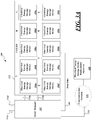
- Figure 3A is a schematic view of the system 100 for utilizing an array of electrical energy storage devices of Figure 2 showing the electrical energy storage devices 106a to 106j in the array categorized according to electrical energy storage device characteristics, according to one non-limiting illustrated embodiment.
- the braces shown in Figure 3A indicate into which category (A, B, C or D) each electrical energy storage device 106a to 106j has been categorized by the smart manager 102 based on electrical energy storage device status information received over data link 108. While each electrical energy storage device 106a to 106j began life with the same capacity, because each electrical energy storage device 106a to 106j is at a different stage of end-of-life in the present example, the internal resistance of each electrical energy storage device 106a to 106j can be dramatically different.
- electrical energy storage devices in category A are 30% of original capacity
- electrical energy storage devices in category B are 40% of original capacity
- electrical energy storage devices in category C are 50% of original capacity
- electrical energy storage devices in category D are 60% of original capacity (see also the table in Figure 3B for reference).
- There may be fewer or additional relevant categories depending on the differences in capacities of the electrical energy storage devices 106a to 106j in the array 112 and other information regarding status of the electrical energy storage devices 106a to 106j in the array 112. These categories may be dynamically updated and/or changed by the smart manager 102 based on the information received over data link 108 regarding status of the electrical energy storage devices 106a to 106j in the array 112.
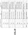
- Figure 3B is a table showing a depletion plan determined by the system 100 for utilizing an array of electrical energy storage devices of Figure 3A based on to the categorizations of the electrical energy storage devices 106a to 106j in the array 112, according to one non-limiting illustrated embodiment.
- the smart manager 102 may be configured to isolate failed/shorted electrical energy storage devices in the array 112 such as failed electrical energy storage device 106c, but it may also put electrical energy storage devices into parallel configurations according to their categories which are based on electrical energy storage device age and thus, individual internal electrical resistance of the electrical energy storage device. For example, as shown in the depletion plan determined by the smart manager 102 illustrated in the table in Figure 3B , electrical energy storage devices 106a, 106b and 106e in category A are to be depleted together, followed by electrical energy storage devices 106d and 106f in category B, followed by electrical energy storage devices 106g, 106h and 106j in category D, and finally followed by electrical energy storage device 106i in category D.
- the categories may be based on electrical energy storage device age and/or other applicable electrical energy storage device status information received over data link 108 indicative of the presently existing internal electrical resistance of the individual electrical energy storage devices 106a to 106j.
- electrical energy storage device age a limited number of electrical energy storage devices are shown for ease of reference.
- a greater benefit may be provided when the system 100 includes a very large array of electrical energy storage devices that are assembled without any regard to their actual capacity. Historically, much care and effort had been required when assembling a large array of electrical energy storage devices, but the system 100 for utilizing an array of electrical energy storage devices as provided herein saves such time and effort by helping to alleviate the need to carefully consider and physically reconfigure the location of individual electrical energy storage devices in the array 112.
- the system 100 also facilitates forecasting actual capacity and thus helps to guarantee available capacity and to actively maintain capacity via maintenance crews that need simply remove and replace battery packs as advised by a computer system of the electrical energy Storage device replacement authority 118 shown in Figure 1 .
- the system 100 facilitates permitting a quality of service (QoS) to be provided to mission critical entities (banks, hospitals, etc.).
- the array 112 may generate an AC voltage that could provide power routinely (in emerging markets) or supplement power (during failures).
- such entities subscribe to a nearly guaranteed capacity that is transparently maintained for them by a service provider that may control the system 100 directly or via communications network 122.
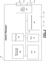
- Figure 4 is a schematic view of the smart manager 102 of the system 100 for utilizing an array of electrical energy storage devices shown in Figure 1 through Figure 3B , according to one non-limiting illustrated embodiment.
- the smart manager 102 includes a controller 410, a communications subsystem 406, a power interface/manager 420, and alternatively includes read-only memory (ROM) 412 random access memory (RAM) 414 and/or other storage 416.
- ROM read-only memory
- RAM random access memory
- the controller 410 for example is a microprocessor, microcontroller, programmable logic controller (PLC), programmable gate array (PGA), application specific integrated circuit (ASIC) or another controller capable of receiving signals from various sensors, performing logical operations, and sending signals to various components.
- the controller 410 may take the form of a microprocessor (e.g ., INTEL or AMD).
- the smart manager 102 may also include one or more non-transitory processor- or computer-readable storage media, for example read only memory (ROM) 412, random access memory (RAM) 414, and other storage 416 (e . g ., solid-state storage media such as flash memory or EEPROM, spinning storage media such as hard disk).
- the non-transitory processor- or computer-readable storage media 412, 414, 416 may be in addition to any non-transitory storage medium (e . g ., registers) which is part of the controller 410.
- the smart manager 102 may include one or more buses 418 (only one illustrated) coupling various components together, for example one or more power buses, instruction buses, data buses, etc.
- the ROM 412 stores instructions and/or data or values for variables or parameters.
- the sets of data may take a variety of forms, for example a lookup table, a set of records in a database, etc.
- the instructions and sets of data or values are executable by the controller 410.
- Execution of the instructions and sets of data or values causes the controller 410 to perform specific acts to cause the smart manager 102 to generate control signals to allow or prevent one or more of the electrical energy storage devices 106a to 106j from accepting a charge and/or releasing energy and to cause power to be drawn from one or more particular electrical energy storage devices of electrical energy storage devices 106a to 106j by one or more connected devices.
- Specific operation of the smart manager 102 is described herein and also below with reference to various flow diagrams ( Figures 5-7 ).
- the instructions and sets of data or values are executable by the controller 410.
- Execution of the instructions and sets of data or values causes the controller 410 to perform specific acts to cause the smart manager 102 to perform the functions of the system 100 described herein. For example, execution of the instructions and sets of data or values causes the controller 410 to perform specific acts to cause the smart manager 102 to determine whether an electrical energy storage device of the plurality of electrical energy storage devices 106a to 106j is faulty based on the received information regarding status of each of the plurality of electrical energy storage devices, and in response to a determination that the electrical energy storage device is faulty, determine to prevent power from being drawn from the electrical energy storage device.
- Execution of the instructions and sets of data or values also causes the controller 410 to perform specific acts to categorize, based on the received information regarding status, electrical energy storage devices of the plurality of electrical energy storage devices 106a to 106j into categories based on matching characteristics regarding one or more of: electrical energy storage device age, present electrical resistance, amount of remaining capacity of original electrical energy storage device capacity, and life expectancy, of various electrical energy storage devices of the plurality of electrical energy storage devices; for each particular category of the categories into which the electrical energy storage devices of the plurality of electrical energy storage devices 106a to 106j were categorized, enable concurrent depletion of charge of each electrical energy storage device in the particular category with each other electrical energy storage device in the particular category; and determine a depletion plan which indicates an order in which a depletion of charge will occur sequentially for each particular category of electrical energy storage device with respect to each other particular category.
- execution of the instructions and sets of data or values causes the controller 410 to perform specific acts to connect, disconnect and/or cause each electrical energy storage device in the particular category to be electrically connected in parallel or series with respect other electrical energy storage devices in the plurality of electrical energy storage devices 106a to 106j in the array 112 shown in Figure 1 to Figure 3 .
- the controller 410 may use RAM 414 in a conventional fashion, for volatile storage of instructions, data, etc.
- the controller 410 may use data store 416 to log or retain information, for example, information regarding status of the electrical energy storage devices 106a to 106j received via data link 108 or other sources.
- the instructions are executable by the controller 410 to control operation of the smart manager 102 in response to input from remote systems such as those of external devices including but not limited to: those of electrical energy storage device replacement authority 118, a remote system of a service provider in control of the system 100, user mobile devices, end user or operator input, etc.
- the control subsystem 402 may also receive signals from various sensors and/or components of an external device via the communications subsystem 406. This information may include information that characterizes or is indicative of the authenticity, authorization level, operation, status, or condition of such components.
- the communications subsystem 406 may include one or more communications modules or components which facilities communications with the various components of external devices (e.g., such as to receive software updates via communication line 110 or data updates of electrical energy storage devices via data link 108).
- the communications subsystem 406 may provide wired and/or wireless communications.
- the communications subsystem 406 may include one or more ports, wireless receivers, wireless transmitters or wireless transceivers to provide wireless signal paths to the various remote components or systems.
- the communications subsystem 406 may, for example, include components enabling short range (e.g., via Bluetooth, near field communication (NFC), radio frequency identification (RFID) components and protocols) or longer range wireless communications (e.g., over a wireless LAN, satellite, or cellular network) and may include one or more modems or one or more Ethernet or other types of communications cards or components for doing so.
- the communications network 122 to which the communications subsystem 406 may be communicatively connected may include one or more bridges or routers suitable to handle network traffic including switched packet type communications protocols (TCP/IP), Ethernet or other networking protocols.
- some or all of the components of the smart manager 102 may be located outside smart manager 102 as a separate device that actuates the switches within the array 112 (e.g., via a wireless control signal) sent via the communications subsystem 406.
- the Power Interface/Manager 420 is controllable by the controller 410 and is configured to provide power to the smart manager 102 and to one or more devices connected to terminals 114c and 114d from the electrical energy storage devices of the array 112 and generally manages power output of the array 112.
- Power Interface/Manager 420 may be configured to regulate the release of power from and/or disconnect one or more of the electrical energy storage devices 106a to 106j of the array 112 according to control signals received from the controller 410 and includes various applicable components operable for doing so such as electrical transformers, switches, converters, rectifiers, etc.
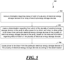
- Figure 5 is a flow diagram showing a high level method 500 in the system 100 for utilizing an array of electrical energy storage devices shown in Figure 1 through Figure 3B , according to one non-limiting illustrated embodiment.
- the system 100 for utilizing an array of electrical energy storage devices receives information regarding status of each of a plurality of electrical energy storage devices of an array of electrical energy storage devices.
- the system 100 for utilizing an array of electrical energy storage makes a determination regarding from which of the plurality of electrical energy storage devices in the array to allow power to be drawn and when to allow power to be drawn from particular electrical energy storage devices of the plurality of electrical energy storage devices in the array. This is based on the received information regarding status of each of the plurality of electrical energy storage devices.
- the system 100 for utilizing an array of electrical energy storage causes power to be drawn from the particular electrical energy storage devices of the plurality of electrical energy storage devices according to the determination made in 504.
- Figure 6 is a flow diagram showing a high level method 600 in the system 100 for utilizing an array of electrical energy storage devices shown in Figure 1 through Figure 3B , according to an alternative illustrated embodiment.
- the system 100 for utilizing an array of electrical energy storage devices receives information regarding status of each of a plurality of electrical energy storage devices of the array of electrical energy storage devices.
- the system 100 for utilizing an array of electrical energy storage devices makes a determination regarding when to allow power to be drawn from each particular electrical energy storage device of the plurality of electrical energy storage devices in the array, based on the received information regarding status of each of the plurality of electrical energy storage devices.
- the system 100 for utilizing an array of electrical energy storage devices causes power to be drawn from the particular electrical energy storage devices of the plurality of electrical energy storage devices according to the determination made in 604.
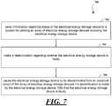
- Figure 7 is a flow diagram showing a high level method 700 in an example one of the electrical energy storage devices (e.g., 106c) shown in Figure 1 through Figure 3B , according to one non-limiting illustrated embodiment.
- the electrical energy storage devices e.g., 106c
- the electrical energy storage device 106c sends information regarding status of the electrical energy storage device 106c to the system 100 for utilizing an array of electrical energy storage devices including the electrical energy storage device 106c.
- the electrical energy storage device 106c makes a determination regarding whether the electrical energy storage device 106c is faulty.
- the electrical energy storage device 106c causes the electrical energy storage device 106c to be disconnected from an electrical circuit of the array 112 if a determination is made by the electrical energy storage device 106c that the electrical energy storage device is faulty.
- the various methods described herein may include additional acts, omit some acts, and/or may perform the acts in a different order than set out in the various flow diagrams.
- ASICs Application Specific Integrated Circuits
- computers e . g ., as one or more programs running on one or more computer systems
- controllers e . g ., microcontrollers
- processors e . g ., microprocessors
- firmware or as various combinations thereof, and that designing the circuitry and/or writing the code for the software and/or firmware would be well within the skill of one of ordinary skill in the art in light of the teachings of this disclosure.
- logic or information can be stored on any non-transitory computer-readable medium for use by or in connection with any processor-related system or method.
- a memory is a nontransitory computer- or processor-readable storage medium that is an electronic, magnetic, optical, or other physical device or means that non-transitorily contains or stores a computer and/or processor program.
- Logic and/or the information can be embodied in any computer-readable medium for use by or in connection with an instruction execution system, apparatus, or device, such as a computer-based system, processor-containing system, or other system that can fetch the instructions from the instruction execution system, apparatus, or device and execute the instructions associated with logic and/or information.
- a "computer-readable medium” can be any physical element that can store the program associated with logic and/or information for use by or in connection with the instruction execution system, apparatus, and/or device.
- the computer-readable medium can be, for example, but is not limited to, an electronic, magnetic, optical, electromagnetic, infrared, or semiconductor system, apparatus or device. More specific examples (a non-exhaustive list) of the computer readable medium would include the following: a portable computer memory device (magnetic, compact flash card, secure digital, or the like), a random access memory (RAM), a read-only memory (ROM), an erasable programmable read-only memory (EPROM, EEPROM, or Flash memory), and a portable compact disc read-only memory (CDROM).
- a portable computer memory device magnetic, compact flash card, secure digital, or the like
- RAM random access memory
- ROM read-only memory
- EPROM erasable programmable read-only memory
- CDROM portable compact disc read-only memory
Landscapes
- Engineering & Computer Science (AREA)
- Power Engineering (AREA)
- Charge And Discharge Circuits For Batteries Or The Like (AREA)
- Secondary Cells (AREA)
- Tests Of Electric Status Of Batteries (AREA)
- Techniques For Improving Reliability Of Storages (AREA)
Applications Claiming Priority (2)
| Application Number | Priority Date | Filing Date | Title |
|---|---|---|---|
| US201461930727P | 2014-01-23 | 2014-01-23 | |
| PCT/US2015/012222 WO2015112584A1 (en) | 2014-01-23 | 2015-01-21 | Systems and methods for utilizing an array of power storage devices, such as batteries |
Publications (3)
| Publication Number | Publication Date |
|---|---|
| EP3097626A1 EP3097626A1 (en) | 2016-11-30 |
| EP3097626A4 EP3097626A4 (en) | 2017-10-11 |
| EP3097626B1 true EP3097626B1 (en) | 2019-03-20 |
Family
ID=53545672
Family Applications (1)
| Application Number | Title | Priority Date | Filing Date |
|---|---|---|---|
| EP15740969.9A Active EP3097626B1 (en) | 2014-01-23 | 2015-01-21 | Systems and methods for utilizing an array of power storage devices, such as batteries |
Country Status (8)
| Country | Link |
|---|---|
| US (1) | US9837842B2 (cg-RX-API-DMAC10.html) |
| EP (1) | EP3097626B1 (cg-RX-API-DMAC10.html) |
| JP (1) | JP6629213B2 (cg-RX-API-DMAC10.html) |
| CN (1) | CN106507694B (cg-RX-API-DMAC10.html) |
| ES (1) | ES2721000T3 (cg-RX-API-DMAC10.html) |
| PH (1) | PH12016501420A1 (cg-RX-API-DMAC10.html) |
| TW (1) | TWI645646B (cg-RX-API-DMAC10.html) |
| WO (1) | WO2015112584A1 (cg-RX-API-DMAC10.html) |
Families Citing this family (19)
| Publication number | Priority date | Publication date | Assignee | Title |
|---|---|---|---|---|
| JP5919525B2 (ja) * | 2011-11-22 | 2016-05-18 | パナソニックIpマネジメント株式会社 | 車両管理システム |
| CN107078360A (zh) * | 2014-08-22 | 2017-08-18 | 佩颂股份有限公司 | 在能量系统中进行串级动态重新配置的方法和装置 |
| ES2934213T3 (es) | 2015-06-05 | 2023-02-20 | Gogoro Inc | Sistemas y métodos para detección de carga de vehículo y respuesta |
| JP6565625B2 (ja) * | 2015-11-17 | 2019-08-28 | オムロン株式会社 | 充放電制御装置、充放電制御システムおよびバッテリ残容量調整方法 |
| DE102016223154A1 (de) | 2016-11-23 | 2018-05-24 | Robert Bosch Gmbh | Batterieeinheit |
| CN107105438B (zh) * | 2017-04-20 | 2020-06-26 | 成都瑞沣信息科技有限公司 | 一种基于QoS的数能一体传输策略设计方法 |
| WO2018222261A1 (en) * | 2017-06-01 | 2018-12-06 | Florida Atlantic University Board Of Trustees | Systems and methods for federated power management |
| FR3076111B1 (fr) * | 2017-12-27 | 2020-01-03 | Commissariat A L'energie Atomique Et Aux Energies Alternatives | Batterie d'accumulateurs electriques |
| KR102156404B1 (ko) * | 2018-01-09 | 2020-09-15 | 주식회사 엘지화학 | 배터리 셀 성능 테스트 장치 및 방법 |
| CN112005425B (zh) * | 2018-04-23 | 2024-07-09 | 松下知识产权经营株式会社 | 数据中心的备用电源系统、备用电池架 |
| WO2020179262A1 (ja) * | 2019-03-06 | 2020-09-10 | パナソニックIpマネジメント株式会社 | バッテリ管理システム、バッテリ管理方法および端末装置 |
| WO2020218032A1 (ja) * | 2019-04-23 | 2020-10-29 | 株式会社Gsユアサ | 蓄電装置、及び、充電状態の低下抑制方法 |
| WO2021019548A1 (en) * | 2019-07-29 | 2021-02-04 | SONALI. M., Jalan | Method and system for managing the usage of a plurality of battery units to power an electric vehicle |
| JP7593711B2 (ja) * | 2020-06-25 | 2024-12-03 | ミルウォーキー エレクトリック ツール コーポレイション | マルチベイ電源の充電均衡 |
| US20230261490A1 (en) * | 2020-07-01 | 2023-08-17 | Vestas Wind Systems A/S | Energy storage adaptive augmentation for load response |
| DE102020210046A1 (de) * | 2020-08-07 | 2022-02-10 | Robert Bosch Gesellschaft mit beschränkter Haftung | Verfahren zum Betreiben eines Batteriesystems |
| WO2024100967A1 (ja) | 2022-11-10 | 2024-05-16 | 株式会社デンソー | 電池監視プログラム、記録媒体、電池監視システム |
| US12530005B2 (en) * | 2023-03-02 | 2026-01-20 | Fluence Energy, Llc | Synthetic inertia for energy systems |
| CN120295571B (zh) * | 2025-03-25 | 2026-05-29 | 郑州祥和电力设计有限公司 | 电力系统中能源设备的分布式能源存储方法及系统 |
Family Cites Families (298)
| Publication number | Priority date | Publication date | Assignee | Title |
|---|---|---|---|---|
| US1387848A (en) | 1916-08-30 | 1921-08-16 | Good Inventions Co | Internal-combustion-engine power plant |
| US3470974A (en) | 1965-10-22 | 1969-10-07 | Dominic L Pefine | Vehicle brake apparatus |
| SE343533B (cg-RX-API-DMAC10.html) | 1969-06-02 | 1972-03-13 | B Engman | |
| US3678455A (en) | 1971-01-14 | 1972-07-18 | Richard S Levey | Cycle theft alarm |
| CH616269A5 (cg-RX-API-DMAC10.html) | 1975-07-18 | 1980-03-14 | Hug Interlizenz Ag | |
| FR2354897A1 (fr) | 1976-06-17 | 1978-01-13 | Peugeot | Dispositif pour l'echange rapide d'une batterie d'accumulateur sur un vehicule electrique |
| US4216839A (en) | 1978-07-20 | 1980-08-12 | Unique Mobility Inc. | Electrically powered motor vehicle |
| FR2565178B1 (fr) | 1984-06-01 | 1987-07-17 | Perret Maurice | Dispositif antivol pour vehicule automobile agissant sur le circuit hydraulique de freinage |
| AU655424B2 (en) | 1990-06-15 | 1994-12-22 | Inn-Room Systems, Inc. | Interactive vending machines |
| US5189325A (en) | 1990-06-15 | 1993-02-23 | General Electric Company | Liquid cooling the rotor of an electrical machine |
| US5187423A (en) | 1991-05-15 | 1993-02-16 | Marton Louis L | System for replenishment of energy stored in a battery on an electric vehicle |
| JPH09508256A (ja) | 1991-08-01 | 1997-08-19 | ウエイブドラィバー・リミテッド | バッテリー式電気車両及び電気供給システム |
| JP2996559B2 (ja) | 1992-01-29 | 2000-01-11 | 本田技研工業株式会社 | 電気自動車の充電状況表示システム |
| US5236069A (en) | 1992-07-02 | 1993-08-17 | Peng, Huan-Yau | Braking device for indoor exercise bicycles |
| US5349535A (en) | 1992-10-20 | 1994-09-20 | Digicomp Research Corporation | Battery condition monitoring and recording system for electric vehicles |
| US5376869A (en) | 1993-02-11 | 1994-12-27 | General Electric Company | Electric vehicle drive train with rollback detection and compensation |
| JPH0731008A (ja) | 1993-07-06 | 1995-01-31 | Toyota Motor Corp | 電気自動車の電力供給制御装置 |
| JPH0736504U (ja) | 1993-11-30 | 1995-07-04 | 株式会社三ツ葉電機製作所 | 疑似エンジン音発生装置 |
| DE4432539C2 (de) | 1993-12-02 | 1996-09-26 | Alfred Zielke | Wegfahrsperre für ein Kraftfahrzeug mit einem Batterieschloß |
| DE4344369C2 (de) | 1993-12-24 | 1997-12-11 | Daimler Benz Ag | Verbrauchsorientierte Fahrleistungsbegrenzung eines Fahrzeugantriebs |
| US6274950B1 (en) * | 1994-03-03 | 2001-08-14 | American Power Conversion | Battery communication system |
| US5631536A (en) | 1994-05-16 | 1997-05-20 | Tseng; Ling-Yuan | Rechargeable battery vending apparatus |
| EP0693813A1 (en) | 1994-07-22 | 1996-01-24 | Chen-Chi Yang | Battery vending system |
| US6900720B2 (en) | 2001-12-27 | 2005-05-31 | Micro Enhanced Technology, Inc. | Vending machines with field-programmable locks |
| JP3089958B2 (ja) | 1994-12-06 | 2000-09-18 | 三菱自動車工業株式会社 | 電気自動車の制動制御装置 |
| JP3264123B2 (ja) | 1995-03-06 | 2002-03-11 | 三菱自動車工業株式会社 | ハイブリッド電気自動車用ナビゲーションシステム |
| US5544784A (en) | 1995-05-26 | 1996-08-13 | Motorola, Inc. | Rechargeable battery vending machine |
| JPH09119839A (ja) | 1995-10-24 | 1997-05-06 | Suzuki Motor Corp | 電気自動車用ナビシステム |
| JP3861321B2 (ja) | 1996-05-02 | 2006-12-20 | トヨタ自動車株式会社 | ハイブリッド車 |
| JP3622020B2 (ja) | 1996-07-31 | 2005-02-23 | ヤマハ発動機株式会社 | 電動自転車のバッテリボックス脱着構造 |
| CA2182630C (en) | 1996-08-02 | 2003-02-11 | Piotr Drozdz | A control system for a hybrid vehicle |
| CN1078560C (zh) | 1996-11-12 | 2002-01-30 | 无限电动汽车体系公司 | 用于电力驱动车辆的蓄电池充电和更换系统 |
| JPH10170293A (ja) | 1996-12-05 | 1998-06-26 | Nissan Motor Co Ltd | 電気自動車の経路探索装置 |
| KR19980045020U (ko) | 1996-12-27 | 1998-09-25 | 김영귀 | 전기자동차의 시동확인장치 |
| JP3910255B2 (ja) | 1997-04-18 | 2007-04-25 | 本田技研工業株式会社 | バッテリ・レンタルシステム |
| US6177879B1 (en) | 1997-05-09 | 2001-01-23 | Honda Giken Kogyo Kabushiki Kaisha | Battery rental system and apparatus |
| JPH10307952A (ja) | 1997-05-09 | 1998-11-17 | Honda Motor Co Ltd | 電動車両レンタルシステムにおけるバッテリ供給装置 |
| JPH1149079A (ja) | 1997-08-04 | 1999-02-23 | Mitsubishi Heavy Ind Ltd | 補助駆動モータ付き自転車 |
| JPH1151681A (ja) | 1997-08-08 | 1999-02-26 | Aisin Aw Co Ltd | 車両用ナビゲーション装置及び記録媒体 |
| JPH11176487A (ja) | 1997-12-10 | 1999-07-02 | Nissan Motor Co Ltd | 電気自動車のバッテリ温度調整装置および調整方法 |
| JPH11205914A (ja) | 1998-01-12 | 1999-07-30 | Yamaha Motor Co Ltd | 電動車両の出力制御装置 |
| US5998963A (en) | 1998-06-11 | 1999-12-07 | Aarseth; Einar | Electric vehicle service center and method for exchanging and charging vehicle batteries |
| US6236333B1 (en) | 1998-06-17 | 2001-05-22 | Lear Automotive Dearborn, Inc. | Passive remote keyless entry system |
| JP2000102102A (ja) | 1998-09-18 | 2000-04-07 | Oki Electric Ind Co Ltd | 電気走行車の残電気量管理及び緊急充電方法及びそのシステム |
| JP2000102103A (ja) | 1998-09-18 | 2000-04-07 | Oki Electric Ind Co Ltd | 電気走行車のバッテリー管理システム |
| US20030209375A1 (en) | 1999-01-25 | 2003-11-13 | Zip Charge Corporation | Electrical vehicle energy supply system, electrical vehicle battery, electrical vehicle battery charging apparatus, battery supply apparatus, and electrical vehicle battery management system |
| US6177867B1 (en) | 1999-04-09 | 2001-01-23 | Eaton Corporation | System for wireless communication between components of a vehicle |
| JP4319289B2 (ja) | 1999-05-25 | 2009-08-26 | 本田技研工業株式会社 | バッテリ交換装置 |
| IT1320305B1 (it) | 1999-05-25 | 2003-11-26 | Honda Motor Co Ltd | Apparecchiatura per il cambio di batterie. |
| US6796396B2 (en) | 1999-06-04 | 2004-09-28 | Deka Products Limited Partnership | Personal transporter |
| JP4229545B2 (ja) | 1999-10-25 | 2009-02-25 | ヤマハ発動機株式会社 | 電動車両及び該電動車両の総合診断装置 |
| US6403251B1 (en) | 2000-01-31 | 2002-06-11 | Moltech Power Systems, Inc | Battery pack with multiple secure modules |
| US20030163434A1 (en) | 2000-02-10 | 2003-08-28 | Barends Steve Hjalmar | Parking fee payment system |
| JP4066589B2 (ja) | 2000-03-06 | 2008-03-26 | トヨタ自動車株式会社 | 内燃機関のアイドリングストップ制御装置およびこれを備える車両 |
| JP4001708B2 (ja) * | 2000-04-28 | 2007-10-31 | 松下電器産業株式会社 | 二次電池の交換方法 |
| JP2002037028A (ja) | 2000-07-26 | 2002-02-06 | Moric Co Ltd | 車両の盗難防止装置 |
| TW500673B (en) | 2000-07-26 | 2002-09-01 | Moric Kabushiki Kaisha | Antitheft device for vehicles |
| JP3651772B2 (ja) | 2000-08-04 | 2005-05-25 | スズキ株式会社 | ハイブリッド車両の制御装置 |
| JP3904135B2 (ja) | 2000-08-04 | 2007-04-11 | スズキ株式会社 | ハイブリッド車両の制御装置 |
| JP4649037B2 (ja) | 2000-09-04 | 2011-03-09 | 株式会社フルタイムシステム | 電子ロッカーシステム |
| US6603394B2 (en) | 2000-12-08 | 2003-08-05 | Spx Corporation | Multi-protocol wireless communication module |
| US7596709B2 (en) | 2000-12-30 | 2009-09-29 | Intel Corporation | CPU power management based on utilization with lowest performance mode at the mid-utilization range |
| FR2825544B1 (fr) | 2001-05-31 | 2003-12-05 | Schlumberger Systems & Service | Procede et dispositif de reservation d'une place de stationnement |
| US6952795B2 (en) | 2001-09-24 | 2005-10-04 | Motorola, Inc. | Method and apparatus for verifying the integrity of control module operation |
| JP2003118397A (ja) | 2001-10-10 | 2003-04-23 | Toyota Industries Corp | バッテリ装置の取り付け構造 |
| US7111179B1 (en) | 2001-10-11 | 2006-09-19 | In-Hand Electronics, Inc. | Method and apparatus for optimizing performance and battery life of electronic devices based on system and application parameters |
| US20030141840A1 (en) | 2002-01-29 | 2003-07-31 | Grant Sanders | Recharging system for personal electronic devices |
| US7392068B2 (en) | 2002-03-01 | 2008-06-24 | Mobilewise | Alternative wirefree mobile device power supply method and system with free positioning |
| DE10209766B4 (de) | 2002-03-05 | 2004-02-19 | Daimlerchrysler Ag | Komponententausch-Warnsystem |
| JP2003262525A (ja) | 2002-03-08 | 2003-09-19 | Nissan Motor Co Ltd | 充電スタンド情報提供装置 |
| US20030236601A1 (en) | 2002-03-18 | 2003-12-25 | Club Car, Inc. | Control and diagnostic system for vehicles |
| US7131005B2 (en) | 2002-06-28 | 2006-10-31 | Motorola, Inc. | Method and system for component authentication of a vehicle |
| US7010682B2 (en) | 2002-06-28 | 2006-03-07 | Motorola, Inc. | Method and system for vehicle authentication of a component |
| KR100461271B1 (ko) | 2002-07-08 | 2004-12-10 | 현대자동차주식회사 | 하이브리드 전기자동차의 아이들 스톱 모드 결정방법 |
| FR2842493B1 (fr) | 2002-07-18 | 2005-09-09 | De Meder Laurent Bourgine | Procede et dispositif de securite pour vehicule deux roues et similaires |
| US6977483B2 (en) * | 2002-08-23 | 2005-12-20 | Nissan Motor Co., Ltd. | Battery pack malfunction detection apparatus and method for detecting a disconnection at a connecting line between a given cell and a corresponding detection terminal |
| TW547534U (en) | 2002-12-27 | 2003-08-11 | Ching-Tian Lin | Press type door lock device used in fireproof doors |
| US7102500B2 (en) | 2003-06-05 | 2006-09-05 | Arachnid, Inc. | System and method for indicating a turn by a vehicle |
| JP2005067453A (ja) | 2003-08-26 | 2005-03-17 | Honda Motor Co Ltd | 移動検出装置を備えた車両 |
| JP2005196568A (ja) | 2004-01-08 | 2005-07-21 | Denso Corp | 車両の部品管理方法及び装置、車両の部品管理データ更新方法及び装置、並びに車両部品管理センタ |
| US7482916B2 (en) | 2004-03-15 | 2009-01-27 | Anita Au | Automatic signaling systems for vehicles |
| CN1953886B (zh) | 2004-06-30 | 2011-05-18 | 福特汽车公司 | 车辆的信息显示器及其显示信息的方法 |
| US20060001399A1 (en) | 2004-07-02 | 2006-01-05 | Lembit Salasoo | High temperature battery system for hybrid locomotive and offhighway vehicles |
| US7340331B2 (en) | 2004-08-12 | 2008-03-04 | Snap-On Incorporated | Vehicle data recorder using digital and analog diagnostic data |
| US20060047400A1 (en) | 2004-08-25 | 2006-03-02 | Raj Prakash | Method and apparatus for braking and stopping vehicles having an electric drive |
| US20060092583A1 (en) * | 2004-10-01 | 2006-05-04 | Alahmad Mahmoud A | Switch array and power management system for batteries and other energy storage elements |
| WO2006044693A2 (en) | 2004-10-18 | 2006-04-27 | Black & Decker Inc. | Cordless power system |
| JP4400414B2 (ja) | 2004-10-25 | 2010-01-20 | 日産自動車株式会社 | 電源装置およびこれを搭載した車両 |
| CN101080693B (zh) | 2004-12-14 | 2010-07-28 | 宝马股份公司 | 用于在具有更新装置的汽车中使用至少一个移动终端设备的系统 |
| US7908020B2 (en) | 2004-12-24 | 2011-03-15 | Donald Pieronek | Architecture for control systems |
| US8412401B2 (en) | 2004-12-30 | 2013-04-02 | Service Solutions U.S. Llc | Method and system for retrieving diagnostic information from a vehicle |
| US8355965B2 (en) | 2005-02-22 | 2013-01-15 | Sharp Kabushiki Kaisha | Battery exchange service system and charging method therefor, and portable device |
| JP2006254650A (ja) | 2005-03-14 | 2006-09-21 | Mitsumi Electric Co Ltd | 電池保護回路 |
| JP2006353042A (ja) | 2005-06-17 | 2006-12-28 | Ntt Docomo Inc | 送電装置、受電装置、認証課金代行装置、充電システム、送電方法、受電方法、充電方法 |
| JP4155287B2 (ja) | 2005-08-01 | 2008-09-24 | トヨタ自動車株式会社 | 車両用自動変速機の変速制御装置 |
| US7617893B2 (en) | 2005-08-02 | 2009-11-17 | Ford Global Technologies, Llc | Method and system for determining final desired wheel power in a hybrid electric vehicle powertrain |
| US7420467B2 (en) | 2005-08-10 | 2008-09-02 | General Motors Corporation | RFID asset management method and system for vehicles |
| JP2007060353A (ja) | 2005-08-25 | 2007-03-08 | Nec Corp | 携帯電話装置、携帯電話システム、電源ユニット、電源ユニット認証方法、およびプログラム |
| JP4155408B2 (ja) | 2005-09-29 | 2008-09-24 | ソニー・エリクソン・モバイルコミュニケーションズ株式会社 | 充電装置および充電システム |
| US7667429B2 (en) | 2005-10-14 | 2010-02-23 | Research In Motion Limited | Battery pack authentication for a mobile device |
| US7999656B2 (en) | 2005-10-26 | 2011-08-16 | Sentrilock, Llc | Electronic lock box with key presence sensing |
| JP5039980B2 (ja) * | 2005-11-14 | 2012-10-03 | 日立ビークルエナジー株式会社 | 二次電池モジュール |
| JP5089883B2 (ja) | 2005-12-16 | 2012-12-05 | 日立ビークルエナジー株式会社 | 蓄電池管理装置 |
| US20070159297A1 (en) | 2005-12-27 | 2007-07-12 | Paulk Howard L | Secure Key Lock Box System |
| US20070145945A1 (en) | 2005-12-28 | 2007-06-28 | Mcginley James W | Method and apparatus to authenticate battery charging device |
| US8026698B2 (en) | 2006-02-09 | 2011-09-27 | Scheucher Karl F | Scalable intelligent power supply system and method |
| US7554288B2 (en) | 2006-03-10 | 2009-06-30 | Atmel Corporation | Random number generator in a battery pack |
| TWI315116B (en) | 2006-05-09 | 2009-09-21 | Ind Tech Res Inst | Battery exchange/recharge apparatus with renewable energy and wireless communication abilities and the management system thereof |
| WO2007133500A2 (en) | 2006-05-10 | 2007-11-22 | Jones Robert M | Electric machine having segmented stator |
| JP2007325458A (ja) | 2006-06-02 | 2007-12-13 | Toyota Motor Corp | 車両用組電池均等化システム |
| JP4929967B2 (ja) * | 2006-10-13 | 2012-05-09 | 富士通株式会社 | バッテリユニット制御方法およびバッテリユニット制御装置 |
| US8118132B2 (en) | 2006-10-18 | 2012-02-21 | The United States Of America As Represented By The Administrator Of The U.S. Environmental Protection Agency | Hydraulic hybrid vehicle method of safe operation |
| US7426910B2 (en) | 2006-10-30 | 2008-09-23 | Ford Global Technologies, Llc | Engine system having improved efficiency |
| JP4799619B2 (ja) | 2006-11-15 | 2011-10-26 | 三菱電機株式会社 | 車両用ハイブリッドエンジンアシストシステム |
| JP2008127894A (ja) | 2006-11-22 | 2008-06-05 | Tokai Rika Co Ltd | 無線通信データ処理装置及び無線通信データ処理方法 |
| JP4793237B2 (ja) | 2006-11-28 | 2011-10-12 | トヨタ自動車株式会社 | 二次電池の充放電制御装置、および、それを備える車両 |
| JP4257360B2 (ja) | 2006-11-30 | 2009-04-22 | Necシステムテクノロジー株式会社 | 電池交換システム、管理装置及び電池交換方法 |
| JP4434217B2 (ja) | 2007-02-14 | 2010-03-17 | 株式会社デンソー | 充電制御装置 |
| JP4714170B2 (ja) | 2007-02-28 | 2011-06-29 | 本田技研工業株式会社 | 燃料電池車両 |
| JP2008235078A (ja) * | 2007-03-22 | 2008-10-02 | Sanoh Industrial Co Ltd | 放電容量ランク別電池セルの選別方法 |
| US7923144B2 (en) | 2007-03-31 | 2011-04-12 | Tesla Motors, Inc. | Tunable frangible battery pack system |
| JP4830953B2 (ja) | 2007-04-09 | 2011-12-07 | トヨタ自動車株式会社 | 車両 |
| US7840239B2 (en) | 2007-05-03 | 2010-11-23 | Texas Instruments Incorporated | Distributed power management |
| JP2008285075A (ja) | 2007-05-18 | 2008-11-27 | Toyota Motor Corp | 車両および車両の故障診断方法 |
| JP4751854B2 (ja) | 2007-05-30 | 2011-08-17 | トヨタ自動車株式会社 | 車両の制御装置、制御方法、その方法を実現するプログラムおよびそのプログラムを記録した記録媒体 |
| US8319605B2 (en) | 2007-06-19 | 2012-11-27 | Magna Electronics, Inc. | Remote vehicle control system utilizing multiple antennas |
| KR101540129B1 (ko) | 2007-07-20 | 2015-07-28 | 퀄컴 인코포레이티드 | 원격 액세스 진단 디바이스 및 이의 방법들 |
| JP4365429B2 (ja) | 2007-07-24 | 2009-11-18 | トヨタ自動車株式会社 | 充電情報を表示するナビゲーション装置およびその装置を備えた車両 |
| JP5017009B2 (ja) | 2007-07-30 | 2012-09-05 | 株式会社東芝 | 並列接続蓄電システム |
| US20090033456A1 (en) | 2007-08-02 | 2009-02-05 | Gilbert Castillo | Compact electronic security locker system |
| JP4513844B2 (ja) | 2007-09-14 | 2010-07-28 | 富士ゼロックス株式会社 | 交換ユニット、シート搬送装置及び画像形成装置 |
| EP2195184A4 (en) | 2007-09-20 | 2011-03-09 | Better Place GmbH | NETWORK FOR ELECTRIC VEHICLES |
| US20090112394A1 (en) | 2007-10-30 | 2009-04-30 | Sosy Technologies Stu, Inc. | Apparatus for collecting, storing and transmitting vehicle information |
| JP5623287B2 (ja) | 2007-12-05 | 2014-11-12 | ジョンソン コントロールズテクノロジーカンパニーJohnson Controls Technology Company | 車両ユーザインターフェースシステム及び方法 |
| AU2008345706A1 (en) | 2007-12-21 | 2009-07-09 | Richard Oliver | Vehicle immobilization system |
| JP2009171646A (ja) | 2008-01-10 | 2009-07-30 | Chugoku Electric Power Co Inc:The | 電気自動車の節電制御装置及びそれを備える電気自動車 |
| JP5020105B2 (ja) | 2008-01-10 | 2012-09-05 | 中国電力株式会社 | 電気自動車の節電運転支援装置及びそれを備える電気自動車 |
| EP2081276A1 (en) | 2008-01-21 | 2009-07-22 | Marco Cipriani | Electro-magnetical device with reversible generator-motor operation |
| US20090198372A1 (en) | 2008-02-05 | 2009-08-06 | Unlimited Range Electric Car Systems Company | Battery charging and transfer system for electrically powered vehicles |
| US8437908B2 (en) | 2008-03-10 | 2013-05-07 | 4 Peaks Technology Llc | Battery monitor system attached to a vehicle wiring harness |
| PL384704A1 (pl) | 2008-03-14 | 2009-09-28 | Chargee Spółka Z Ograniczoną Odpowiedzialnością | Samoobsługowe urządzenie do ładowania baterii i obsługi urządzeń elektronicznych oraz sposób kontrolowania przebiegu ładowania baterii |
| US7898439B2 (en) | 2008-03-20 | 2011-03-01 | Isabelle Bettez | Bicycle rental system and station |
| WO2009128080A1 (en) | 2008-04-17 | 2009-10-22 | Eran Ofek | Method and apparatus for rapidly charging a battery |
| US8063762B2 (en) | 2008-05-23 | 2011-11-22 | Goren Trade Inc. | Alarm system for monitoring at rural locations |
| US7728548B2 (en) | 2008-06-02 | 2010-06-01 | Physio-Control, Inc. | Defibrillator battery authentication system |
| US20090294188A1 (en) | 2008-06-02 | 2009-12-03 | Monty Cole | Motorized axle for use with environmentally friendly vehicles |
| JP4582205B2 (ja) | 2008-06-12 | 2010-11-17 | トヨタ自動車株式会社 | 電動車両 |
| JPWO2010005052A1 (ja) | 2008-07-10 | 2012-01-05 | 見敏 石井 | 電気自動車の蓄電池管理の表示方法 |
| JP5202143B2 (ja) | 2008-07-11 | 2013-06-05 | 株式会社一宮電機 | アウターロータ型車両用発電機 |
| KR20100012401A (ko) | 2008-07-28 | 2010-02-08 | 콘티넨탈 오토모티브 시스템 주식회사 | 자동차의 고장 진단 방법 및 장치 |
| US8006793B2 (en) | 2008-09-19 | 2011-08-30 | Better Place GmbH | Electric vehicle battery system |
| US20100094496A1 (en) | 2008-09-19 | 2010-04-15 | Barak Hershkovitz | System and Method for Operating an Electric Vehicle |
| US7993155B2 (en) | 2008-09-19 | 2011-08-09 | Better Place GmbH | System for electrically connecting batteries to electric vehicles |
| EP2323866A2 (en) | 2008-09-19 | 2011-05-25 | Better Place GmbH | System and method for operating an electric vehicle |
| US8035349B2 (en) | 2008-09-30 | 2011-10-11 | Toyota Motor Engineering & Manufacturing North America, Inc. | Systems and methods for absorbing waste electricity from regenerative braking in hybridized vehicles |
| US8575897B2 (en) | 2008-10-03 | 2013-11-05 | Denso Corporation | Battery temperature control system |
| US8229625B2 (en) | 2008-10-03 | 2012-07-24 | Robert Bosch Gmbh | Method and apparatus for customizing a wireless network architecture |
| US7979147B1 (en) | 2008-10-06 | 2011-07-12 | James Francis Dunn | Engine sound replication device |
| WO2010042517A1 (en) * | 2008-10-07 | 2010-04-15 | Boston-Power, Inc. | Li-ion battery array for vehicle and other large capacity applications |
| US9960461B2 (en) | 2008-10-15 | 2018-05-01 | General Electric Company | System and method for temperature control of multi-battery systems |
| US8085034B2 (en) | 2008-10-31 | 2011-12-27 | Yaniv Sirton | Managing charging of electric vehicles |
| JP5509577B2 (ja) | 2008-10-31 | 2014-06-04 | 日本電気株式会社 | 充電装置、管理装置、バッテリシステム、バッテリ管理方法、およびバッテリ管理プログラム |
| JP5453769B2 (ja) | 2008-11-06 | 2014-03-26 | トヨタ自動車株式会社 | 車両用電池診断システムおよび車両用電池診断方法 |
| JP2010148246A (ja) | 2008-12-18 | 2010-07-01 | Alpha Corp | 電気自動車の充電システム |
| US9505317B2 (en) | 2008-12-22 | 2016-11-29 | General Electric Company | System and method for electric vehicle charging and billing using a wireless vehicle communication service |
| US8068952B2 (en) | 2008-12-23 | 2011-11-29 | Telefonaktiebolaget L M Ericsson (Publ) | Interworking among automobile buses, portable user equipment and mobile networks |
| US8342583B2 (en) | 2009-01-30 | 2013-01-01 | GM Global Technology Operations LLC | Vehicle panel control system |
| US20100198535A1 (en) | 2009-02-03 | 2010-08-05 | Leviton Manufacturing Co., Inc. | Power distribution unit monitoring network and components |
| US8791790B2 (en) | 2009-02-10 | 2014-07-29 | Yikes Llc | System and method for accessing a structure using a mobile device |
| JP4743293B2 (ja) | 2009-02-17 | 2011-08-10 | 日本電気株式会社 | 電力配分システムおよび方法 |
| JP5249079B2 (ja) | 2009-02-17 | 2013-07-31 | 株式会社 動研 | 電動装置のバッテリ交換システム |
| JP2010200405A (ja) | 2009-02-23 | 2010-09-09 | Toyota Motor Corp | 充電器付建物 |
| JP5184406B2 (ja) | 2009-03-11 | 2013-04-17 | 富士重工業株式会社 | 電気自動車の制御装置 |
| KR101197349B1 (ko) | 2009-03-17 | 2012-11-05 | 알리스 에이알케이 코. 엘티디. | 플러그-인 하이브리드 및 전기 차량을 위한 전력 관리 방법 |
| ES2428724T3 (es) | 2009-03-27 | 2013-11-11 | Honda Motor Co., Ltd. | Vehículo eléctrico montado a horcajadas |
| DE102009016869A1 (de) | 2009-04-08 | 2010-10-14 | Li-Tec Battery Gmbh | Verfahren zum Betreiben eines Fahrzeugs |
| US8330419B2 (en) | 2009-04-10 | 2012-12-11 | The Regents Of The University Of Michigan | Dynamically reconfigurable framework for a large-scale battery system |
| US8681457B2 (en) | 2009-04-23 | 2014-03-25 | Toyota Jidosha Kabushiki Kaisha | Power source system for electric powered vehicle and control method therefor |
| DE102009019753A1 (de) | 2009-05-02 | 2010-11-04 | Daimler Ag | Verfahren und Anordnung zur Datenkommunikation zwischen einem Diensteanbieter und einem Fahrzeug |
| JP2010269686A (ja) | 2009-05-21 | 2010-12-02 | Asahi Denso Co Ltd | ターンシグナルスイッチ装置 |
| TWM379789U (en) | 2009-06-05 | 2010-05-01 | Chen Tech Electric Mfg Co Ltd | Battery power control device for variable voltage outputs |
| TWM371880U (en) | 2009-06-05 | 2010-01-01 | Chen Tech Electric Mfg Co Ltd | Battery detection device with anti-noise function |
| TW201043986A (en) | 2009-06-05 | 2010-12-16 | Chen Tech Electric Mfg Co Ltd | Stand-alone battery detection device |
| TW201044266A (en) | 2009-06-05 | 2010-12-16 | Chen Tech Electric Mfg Co Ltd | Coding system having battery parameter setting function |
| US9174570B2 (en) | 2009-06-09 | 2015-11-03 | Joseph Gasper | Wireless light and accessory control system for golf carts and other vehicles |
| JP2010288319A (ja) | 2009-06-09 | 2010-12-24 | Toyota Industries Corp | 充電装置 |
| KR101102618B1 (ko) | 2009-07-07 | 2012-01-03 | 경원대학교 산학협력단 | 전기자동차의 배터리교체 충전에 따른 부가서비스 제공 방법 및 시스템 |
| US9608460B2 (en) | 2009-07-30 | 2017-03-28 | Aerovironment, Inc. | Remote rechargeable monitoring system and method |
| WO2011014773A2 (en) | 2009-07-31 | 2011-02-03 | Deka Products Limited Partnership | Systems, methods and apparatus for vehicle battery charging |
| JP5062229B2 (ja) | 2009-08-05 | 2012-10-31 | 株式会社デンソー | 給電コントローラおよび給電システム |
| JP5413042B2 (ja) | 2009-08-07 | 2014-02-12 | 株式会社デンソー | 蓄電情報出力装置および蓄電情報出力システム |
| KR100971278B1 (ko) | 2009-09-08 | 2010-07-20 | 동아대학교 산학협력단 | 모터사이클 도난 방지 방법 및 시스템 |
| US20110082621A1 (en) | 2009-10-02 | 2011-04-07 | Eric Berkobin | Method and system for predicting battery life based on vehicle battery, usage, and environmental data |
| KR20110041783A (ko) | 2009-10-16 | 2011-04-22 | 한국과학기술원 | 전기 구동 이동체의 에너지 절약 제어시스템 및 제어방법 |
| TWM379269U (en) | 2009-10-26 | 2010-04-21 | Chu Li Hwa | Fixed-point type battery exchange apparatus |
| US20110106329A1 (en) | 2009-11-03 | 2011-05-05 | GRIDbot, LLC | Methods and apparatus for charging station with sms user interface |
| JP4893804B2 (ja) | 2009-11-05 | 2012-03-07 | トヨタ自動車株式会社 | 車両用電源装置 |
| DE102009052853B4 (de) | 2009-11-11 | 2017-07-20 | Dr. Ing. H.C. F. Porsche Aktiengesellschaft | Verfahren zur Reichweitenabschätzung eines Kraftfahrzeugs |
| FR2952612B1 (fr) | 2009-11-17 | 2012-01-13 | Eurocopter France | Aeronef a grande distance franchissable et a vitesse d'avancement elevee en vol de croisiere |
| JP4877382B2 (ja) | 2009-11-20 | 2012-02-15 | トヨタ自動車株式会社 | ハイブリッド自動車およびその制御方法 |
| JP5407835B2 (ja) | 2009-12-18 | 2014-02-05 | 日産自動車株式会社 | 電動車両用バッテリの取り付け構造 |
| US9896044B2 (en) | 2009-12-18 | 2018-02-20 | Fca Us Llc | System and method for vehicle range extension on detection of a low fuel condition |
| FR2954265B1 (fr) | 2009-12-22 | 2012-05-04 | Jcdecaux Sa | Systeme automatique de stockage de cycles, cycle pour un tel systeme et structure d'accueil pour un tel cycle. |
| JP5399884B2 (ja) | 2009-12-22 | 2014-01-29 | 株式会社東海理化電機製作所 | ターンシグナル点灯制御装置 |
| JP4915447B2 (ja) | 2009-12-25 | 2012-04-11 | トヨタ自動車株式会社 | バッテリの車両搭載構造 |
| JP2011142704A (ja) | 2010-01-05 | 2011-07-21 | Mitsubishi Heavy Ind Ltd | 作業車の二次電池充電マネージメント方法及び充電システム |
| US20110169447A1 (en) | 2010-01-11 | 2011-07-14 | Leviton Manufacturing Co., Inc. | Electric vehicle supply equipment |
| US20110200193A1 (en) | 2010-02-12 | 2011-08-18 | Daniel Ray Blitz | Method and apparatus for controlling the recharging of electric vehicles and detecting stolen vehicles and vehicular components |
| DK2362362T3 (da) | 2010-02-18 | 2013-07-15 | Kapsch Trafficcom Ag | Fremgangsmåde til opladning af eldrevne køretøjer i geografisk fordelte opladningsstationer |
| JP5017398B2 (ja) | 2010-03-09 | 2012-09-05 | 日立オートモティブシステムズ株式会社 | 経路計画装置及び経路計画システム |
| TWM385047U (en) | 2010-03-12 | 2010-07-21 | Chen Tech Electric Mfg Co Ltd | Structure of RFID wireless identification information battery pack |
| JP2011211880A (ja) | 2010-03-31 | 2011-10-20 | Motion:Kk | 車載バッテリー充電システム、管理サーバー、管理サーバーの制御方法、及び、プログラム |
| WO2011126600A1 (en) | 2010-04-07 | 2011-10-13 | Silver Spring Networks, Inc. | Systems and methods for charging electric vehicles |
| JP5499872B2 (ja) | 2010-04-21 | 2014-05-21 | ソニー株式会社 | バッテリー制御装置、バッテリー制御方法及びプログラム |
| JP5895839B2 (ja) | 2010-04-26 | 2016-03-30 | 日本電気株式会社 | 二次電池状態管理システム、充電器、二次電池状態管理方法及び電気特性測定方法 |
| US9059595B2 (en) | 2010-04-28 | 2015-06-16 | Toyota Jidosha Kabushiki Kaisha | Charging control method for secondary battery and control device |
| JP5585188B2 (ja) | 2010-04-30 | 2014-09-10 | ソニー株式会社 | バッテリモジュール、電動移動体、及びバッテリモジュールの放電制御方法 |
| US8498771B2 (en) | 2010-05-05 | 2013-07-30 | Ford Global Technologies, Llc | Wireless vehicle servicing |
| EP2385349A1 (en) | 2010-05-06 | 2011-11-09 | Leica Geosystems AG | Method and guidance unit for guiding battery-operated transportation means to reconditioning stations |
| US8838308B2 (en) | 2010-05-27 | 2014-09-16 | Boxx Corp. | Two wheeled vehicle with modular features |
| US9090207B2 (en) | 2010-05-27 | 2015-07-28 | Boxx Corp. | Two wheeled vehicle with lighting system that generates defined image on riding surface |
| JP5450812B2 (ja) | 2010-05-31 | 2014-03-26 | 三洋電機株式会社 | 電池システム、電動車両、移動体、電力貯蔵装置、電源装置及び電池電圧検出装置 |
| WO2011156776A2 (en) | 2010-06-10 | 2011-12-15 | The Regents Of The University Of California | Smart electric vehicle (ev) charging and grid integration apparatus and methods |
| US8035341B2 (en) | 2010-07-12 | 2011-10-11 | Better Place GmbH | Staged deployment for electrical charge spots |
| US8853997B2 (en) | 2010-07-20 | 2014-10-07 | Superior Electron Llc | Apparatus, system and method for charging batteries |
| WO2012012008A2 (en) | 2010-07-23 | 2012-01-26 | Electric Transportation Engineering Corp. | System for advertising and communicating at a vehicle charging station and method of using the same |
| US8692663B2 (en) | 2010-08-10 | 2014-04-08 | General Motors Llc. | Wireless monitoring of battery for lifecycle management |
| KR20120020554A (ko) | 2010-08-30 | 2012-03-08 | 삼성전기주식회사 | 전기 차량용 통합형 충전 장치 |
| DE102010040388A1 (de) | 2010-09-08 | 2012-03-08 | Siemens Aktiengesellschaft | Serviceautomat zum Beziehen und/oder Aufladen eines Energiespeichers für ein Elektrofahrrad |
| JP5600530B2 (ja) | 2010-09-09 | 2014-10-01 | 株式会社東海理化電機製作所 | 車両の無線通信システム |
| US8593252B2 (en) | 2010-09-16 | 2013-11-26 | Sentrilock, Llc | Electronic lock box proximity access control |
| US20120078413A1 (en) | 2010-09-29 | 2012-03-29 | Baker Jr Therman A | Secured electrical recharging facility method and apparatus |
| US20120109519A1 (en) | 2010-10-27 | 2012-05-03 | Honda Motor Co., Ltd. | System and method for routing bev to charging station |
| US8766648B2 (en) | 2010-11-01 | 2014-07-01 | Ford Global Technologies, Llc | Method and system for determining an operating characteristic associated with an inductor in a power converter system |
| US8326259B2 (en) | 2010-11-05 | 2012-12-04 | GM Global Technology Operations LLC | Remote application of vehicle component settings |
| US20120126969A1 (en) | 2010-11-23 | 2012-05-24 | Aptera Motors, Inc. | Automotive vehicle warning system |
| US8335547B2 (en) | 2010-12-16 | 2012-12-18 | General Motors Llc | System and method for providing discharge authorization to a battery-powered vehicle via a telematics system |
| US9166515B2 (en) | 2010-12-20 | 2015-10-20 | Toyota Jidosha Kabushiki Kaisha | Electrically powered vehicle and method for controlling the same |
| KR20120071243A (ko) | 2010-12-22 | 2012-07-02 | 한국전자통신연구원 | 차량의 소프트웨어 업데이트 장치 및 그 방법 |
| JP5665224B2 (ja) | 2011-01-14 | 2015-02-04 | 株式会社Jsol | 蓄電池システム |
| TWI424381B (zh) | 2011-01-28 | 2014-01-21 | Ind Tech Res Inst | 電動車的駕駛輔助方法及駕駛輔助系統 |
| US9079586B2 (en) | 2011-02-17 | 2015-07-14 | Ford Global Technologies, Llc | Method and system for extending an operating range of a motor vehicle |
| JP5725544B2 (ja) | 2011-03-01 | 2015-05-27 | オムロンオートモーティブエレクトロニクス株式会社 | 電力変換装置および電力制御方法 |
| EP2642630B1 (en) | 2011-03-25 | 2016-06-29 | Sanyo Electric Co., Ltd. | Battery system, electric-powered vehicle, mobile object, power storage device, power supply device |
| US10778008B2 (en) | 2011-03-28 | 2020-09-15 | Paul S. Levy | Method and process for acquiring and delivering electric vehicle owner-operator preference data which is used to schedule and regulate the charging of multiple electric vehicle batteries within a shared local power distribution network |
| US20120248868A1 (en) | 2011-04-04 | 2012-10-04 | Fahim Usshihab Mobin | Swappable battery car and battery car station |
| US8731974B2 (en) | 2011-04-05 | 2014-05-20 | Hartford Fire Insurance Company | Systems and methods associated with insurance for electric vehicles |
| JP2012228165A (ja) | 2011-04-07 | 2012-11-15 | Honda Motor Co Ltd | 電気自動車充電制御システム |
| JP5668136B2 (ja) * | 2011-04-18 | 2015-02-12 | 日立オートモティブシステムズ株式会社 | 蓄電装置 |
| US9123035B2 (en) | 2011-04-22 | 2015-09-01 | Angel A. Penilla | Electric vehicle (EV) range extending charge systems, distributed networks of charge kiosks, and charge locating mobile apps |
| US20120296512A1 (en) | 2011-04-26 | 2012-11-22 | University Of Cincinnati | Method and system for electric vehicle battery prognostics and health management |
| WO2012160407A1 (en) | 2011-05-20 | 2012-11-29 | Better Place GmbH | Multi-motor latch assembly |
| US9060213B2 (en) | 2011-05-24 | 2015-06-16 | Spireon, Inc. | Battery monitoring system |
| US8265816B1 (en) | 2011-05-27 | 2012-09-11 | General Electric Company | Apparatus and methods to disable an electric vehicle |
| ES2720202T3 (es) | 2011-07-26 | 2019-07-18 | Gogoro Inc | Aparato, método y artículo para un compartimento de dispositivo de almacenamiento de energía |
| EP2737593B1 (en) * | 2011-07-26 | 2023-11-22 | Gogoro Inc. | Apparatus, method and article for authentication, security and control of power storage devices, such as batteries |
| EP2736760A4 (en) | 2011-07-26 | 2015-11-04 | Gogoro Inc | DYNAMIC LIMITATION OF VEHICLE OPERATION FOR POSSIBLE ECONOMIC USE |
| CN103858305A (zh) | 2011-07-26 | 2014-06-11 | Gogoro有限公司 | 用于在预订电能存储设备的收集、充电及分配机处预订电能存储设备的装置、方法及物品 |
| WO2013016545A2 (en) | 2011-07-26 | 2013-01-31 | Gogoro, Inc. | Apparatus, method and article for providing vehicle diagnostic data |
| EP2737572B1 (en) | 2011-07-26 | 2022-08-24 | Gogoro Inc. | Thermal management of components in electric motor drive vehicles |
| TWI560637B (en) | 2011-07-26 | 2016-12-01 | Gogoro Inc | Apparatus, method and article for providing information regarding availability of power storage devices at a power storage device collection, charging and distribution machine |
| JP6010619B2 (ja) | 2011-07-26 | 2016-10-19 | ゴゴロ インク | ユーザープロファイルに基づいた電池などの電力貯蔵装置の認証、セキュリティ、及び制御のための装置、方法、及び物品 |
| ES2701745T3 (es) | 2011-07-26 | 2019-02-25 | Gogoro Inc | Aparato, método y artículo para la redistribución de dispositivos de almacenamiento de energía, como por ejemplo baterías, entre máquinas de recogida, carga y distribución |
| ES2791691T3 (es) | 2011-07-26 | 2020-11-05 | Gogoro Inc | Aparato, método y artículo para la recogida, carga y distribución de dispositivos de almacenamiento de energía, como por ejemplo baterías |
| TWI618020B (zh) | 2011-07-26 | 2018-03-11 | 睿能創意公司 | 用於提供電力儲存器件收集、充電及分配機器之位置之方法、系統及電腦可讀媒體 |
| TWI485572B (zh) | 2011-07-26 | 2015-05-21 | 睿能創意公司 | 用於車輛中之電力儲存器件之實體保全之裝置、方法及物品 |
| CN103814394A (zh) | 2011-08-16 | 2014-05-21 | 佳境有限公司 | 电动交通工具网络中的负载的估计和管理 |
| EP2744682A2 (en) | 2011-08-16 | 2014-06-25 | Better Place GmbH | Identification of an electric vehicle adjacent to a power replenishment station |
| WO2013042216A1 (ja) | 2011-09-21 | 2013-03-28 | トヨタ自動車株式会社 | 電動車両の充電システムおよび充電制御方法 |
| US8539990B2 (en) | 2011-09-28 | 2013-09-24 | Tesla Motors, Inc. | Vehicle port door with wirelessly actuated unlatching assembly |
| TWI569992B (zh) | 2011-10-05 | 2017-02-11 | 睿能創意公司 | 電動車輛待命模式之可偵測指示 |
| WO2013056024A1 (en) | 2011-10-12 | 2013-04-18 | Gogoro, Inc. | Electric devices |
| KR20130046234A (ko) * | 2011-10-27 | 2013-05-07 | 삼성에스디아이 주식회사 | 배터리 팩 및 이의 제어 방법 |
| ES2692526T3 (es) | 2011-11-08 | 2018-12-04 | Gogoro Inc. | Aparato, método y artículo para la seguridad de vehículos |
| US20140310165A1 (en) | 2011-11-16 | 2014-10-16 | Tricopian, Llc | Two-way vending |
| US20130132307A1 (en) | 2011-11-17 | 2013-05-23 | Rwdg Enterprises, Inc. | Managing the use of secure compartments in charging stations for portable electronic devices |
| WO2013080211A1 (en) | 2011-12-02 | 2013-06-06 | Better Place GmbH | Battery selection system and method |
| JP2013123279A (ja) | 2011-12-09 | 2013-06-20 | Honda Motor Co Ltd | 電動車両 |
| US8620506B2 (en) | 2011-12-21 | 2013-12-31 | Ford Global Technologies, Llc | Method and system for thermal management of a high voltage battery for a vehicle |
| WO2013102894A1 (en) | 2012-01-04 | 2013-07-11 | Better Place GmbH | System and method for management of electric power consumption |
| WO2013108246A2 (en) | 2012-01-17 | 2013-07-25 | Better Place GmbH | Approximation of remaining travelable distance of a vehicle powered by a battery |
| JP5919857B2 (ja) | 2012-02-03 | 2016-05-18 | スズキ株式会社 | 充放電制御装置 |
| WO2013118113A2 (en) | 2012-02-06 | 2013-08-15 | Better Place GmbH | Method and system for optimization of deployment of battery service stations for electric vehicles |
| US8907629B2 (en) | 2012-02-28 | 2014-12-09 | Tesla Motors, Inc. | Electric vehicle battery lifetime optimization operational mode |
| DE102012101799A1 (de) | 2012-03-02 | 2013-09-05 | ropa development GmbH | Netzinfrastrukturkomponente, Verbundsystem mit einer Mehrzahl von Netzinfrastrukturkomponenten sowie Verwendung des Verbundsystems |
| DE102012101800A1 (de) | 2012-03-02 | 2013-09-05 | ropa development GmbH | Versorgungsnetzkomponente für ein Versorgungsnetz |
| US20130254097A1 (en) | 2012-03-20 | 2013-09-26 | At&T Intellectual Property I, L.P. | Methods, Systems, and Products for Charging Batteries |
| WO2013142154A1 (en) | 2012-03-20 | 2013-09-26 | Tricopian, Llc | Two-way exchange vending |
| IL218923A (en) | 2012-03-29 | 2016-12-29 | Better Place GmbH | Battery service system for electric vehicle |
| US9231440B2 (en) | 2012-04-18 | 2016-01-05 | Samsung Sdi Co., Ltd. | Power supply apparatus and controlling method of the same |
| US9381826B2 (en) | 2012-10-19 | 2016-07-05 | Gogoro Inc. | Battery configuration for an electric vehicle |
| US9216687B2 (en) | 2012-11-16 | 2015-12-22 | Gogoro Inc. | Apparatus, method and article for vehicle turn signals |
| US9854438B2 (en) | 2013-03-06 | 2017-12-26 | Gogoro Inc. | Apparatus, method and article for authentication, security and control of portable charging devices and power storage devices, such as batteries |
| JP2016521389A (ja) | 2013-03-12 | 2016-07-21 | ゴゴロ インク | ポータブル電力蓄積デバイス交換プランを変更するための装置、方法、および物品 |
| US11222485B2 (en) | 2013-03-12 | 2022-01-11 | Gogoro Inc. | Apparatus, method and article for providing information regarding a vehicle via a mobile device |
| US8798852B1 (en) | 2013-03-14 | 2014-08-05 | Gogoro, Inc. | Apparatus, system, and method for authentication of vehicular components |
| BR112015023047A2 (pt) | 2013-03-15 | 2017-07-18 | Gogoro Inc | sistema modular para coleta e distribuição de dispositivos de armazenagento elétricos |
| US9770996B2 (en) | 2013-08-06 | 2017-09-26 | Gogoro Inc. | Systems and methods for powering electric vehicles using a single or multiple power cells |
-
2015
- 2015-01-21 TW TW104101911A patent/TWI645646B/zh active
- 2015-01-21 ES ES15740969T patent/ES2721000T3/es active Active
- 2015-01-21 US US14/601,840 patent/US9837842B2/en active Active
- 2015-01-21 CN CN201580015333.4A patent/CN106507694B/zh active Active
- 2015-01-21 WO PCT/US2015/012222 patent/WO2015112584A1/en not_active Ceased
- 2015-01-21 JP JP2016547531A patent/JP6629213B2/ja active Active
- 2015-01-21 EP EP15740969.9A patent/EP3097626B1/en active Active
-
2016
- 2016-07-19 PH PH12016501420A patent/PH12016501420A1/en unknown
Non-Patent Citations (1)
| Title |
|---|
| None * |
Also Published As
| Publication number | Publication date |
|---|---|
| JP2017509867A (ja) | 2017-04-06 |
| CN106507694A (zh) | 2017-03-15 |
| TW201541801A (zh) | 2015-11-01 |
| TWI645646B (zh) | 2018-12-21 |
| ES2721000T3 (es) | 2019-07-26 |
| EP3097626A4 (en) | 2017-10-11 |
| US20150207355A1 (en) | 2015-07-23 |
| EP3097626A1 (en) | 2016-11-30 |
| WO2015112584A1 (en) | 2015-07-30 |
| US9837842B2 (en) | 2017-12-05 |
| PH12016501420B1 (en) | 2016-09-14 |
| PH12016501420A1 (en) | 2016-09-14 |
| CN106507694B (zh) | 2019-04-30 |
| JP6629213B2 (ja) | 2020-01-15 |
Similar Documents
| Publication | Publication Date | Title |
|---|---|---|
| US9837842B2 (en) | Systems and methods for utilizing an array of power storage devices, such as batteries | |
| CN116529978B (zh) | 大型电池管理系统 | |
| US11245268B1 (en) | Mode-based disabling of communiction bus of a battery management system | |
| Ci et al. | Reconfigurable battery techniques and systems: A survey | |
| KR101473385B1 (ko) | 전력 저장 장치, 이를 이용한 전력 저장 시스템 및 전력 저장 시스템의 구성 방법 | |
| Rahimi-Eichi et al. | Battery management system: An overview of its application in the smart grid and electric vehicles | |
| EP3054554B1 (en) | Battery pack and method of controlling the same | |
| US9088052B2 (en) | Battery multi-series system and communication method thereof | |
| US9136715B2 (en) | Rechargeable battery pack and method of charge/discharge equalizing | |
| US20170170449A1 (en) | System and method for a dynamically configurable power distribution control and management system | |
| US12224603B2 (en) | Mode-based disabling of communication bus of a battery management system | |
| WO2009128079A1 (en) | Method and apparatus of performance balancing of battery cells | |
| EP3098926B1 (en) | Method and system for self-registration and self-assembly of electrical devices | |
| CN106300546A (zh) | 一种用于电池管理系统的隔离均衡电路及均衡方法 | |
| KR20210087404A (ko) | 하이브리드 밸런싱 기술을 이용한 배터리 셀의 충방전 장치 및 그 방법 | |
| CN205791596U (zh) | 一种电动车及其电池包维护系统 | |
| KR20130067676A (ko) | 배터리 전압 측정 장치 및 방법 | |
| US20130141049A1 (en) | Battery and method for operating a battery | |
| Bharath et al. | Supercapacitor Assisted Self‐Reconfigurable Battery System for Enhanced Cell Balancing and Voltage Stability | |
| US20260066369A1 (en) | Battery management device, energy storage device including same and controlling method of energy storage device | |
| KR20250081205A (ko) | 안전성이 개선된 배터리 팩 시스템 | |
| TWM440538U (en) | Hybrid combination |
Legal Events
| Date | Code | Title | Description |
|---|---|---|---|
| PUAI | Public reference made under article 153(3) epc to a published international application that has entered the european phase |
Free format text: ORIGINAL CODE: 0009012 |
|
| 17P | Request for examination filed |
Effective date: 20160823 |
|
| AK | Designated contracting states |
Kind code of ref document: A1 Designated state(s): AL AT BE BG CH CY CZ DE DK EE ES FI FR GB GR HR HU IE IS IT LI LT LU LV MC MK MT NL NO PL PT RO RS SE SI SK SM TR |
|
| AX | Request for extension of the european patent |
Extension state: BA ME |
|
| DAX | Request for extension of the european patent (deleted) | ||
| A4 | Supplementary search report drawn up and despatched |
Effective date: 20170911 |
|
| RIC1 | Information provided on ipc code assigned before grant |
Ipc: H02J 7/00 20060101ALI20170905BHEP Ipc: G01R 31/36 20060101ALI20170905BHEP Ipc: H01M 10/44 20060101ALI20170905BHEP Ipc: H02J 7/34 20060101ALI20170905BHEP Ipc: H02J 7/04 20060101AFI20170905BHEP |
|
| STAA | Information on the status of an ep patent application or granted ep patent |
Free format text: STATUS: EXAMINATION IS IN PROGRESS |
|
| RIC1 | Information provided on ipc code assigned before grant |
Ipc: H02J 7/00 20060101ALI20180430BHEP Ipc: H02J 7/04 20060101AFI20180430BHEP Ipc: H02J 7/34 20060101ALI20180430BHEP Ipc: H01M 10/44 20060101ALI20180430BHEP Ipc: G01R 31/36 20060101ALI20180430BHEP |
|
| 17Q | First examination report despatched |
Effective date: 20180515 |
|
| GRAP | Despatch of communication of intention to grant a patent |
Free format text: ORIGINAL CODE: EPIDOSNIGR1 |
|
| STAA | Information on the status of an ep patent application or granted ep patent |
Free format text: STATUS: GRANT OF PATENT IS INTENDED |
|
| INTG | Intention to grant announced |
Effective date: 20181109 |
|
| GRAS | Grant fee paid |
Free format text: ORIGINAL CODE: EPIDOSNIGR3 |
|
| GRAA | (expected) grant |
Free format text: ORIGINAL CODE: 0009210 |
|
| STAA | Information on the status of an ep patent application or granted ep patent |
Free format text: STATUS: THE PATENT HAS BEEN GRANTED |
|
| AK | Designated contracting states |
Kind code of ref document: B1 Designated state(s): AL AT BE BG CH CY CZ DE DK EE ES FI FR GB GR HR HU IE IS IT LI LT LU LV MC MK MT NL NO PL PT RO RS SE SI SK SM TR |
|
| REG | Reference to a national code |
Ref country code: GB Ref legal event code: FG4D |
|
| REG | Reference to a national code |
Ref country code: CH Ref legal event code: EP |
|
| REG | Reference to a national code |
Ref country code: DE Ref legal event code: R096 Ref document number: 602015026764 Country of ref document: DE |
|
| REG | Reference to a national code |
Ref country code: AT Ref legal event code: REF Ref document number: 1111499 Country of ref document: AT Kind code of ref document: T Effective date: 20190415 |
|
| REG | Reference to a national code |
Ref country code: IE Ref legal event code: FG4D |
|
| REG | Reference to a national code |
Ref country code: NL Ref legal event code: FP |
|
| REG | Reference to a national code |
Ref country code: ES Ref legal event code: FG2A Ref document number: 2721000 Country of ref document: ES Kind code of ref document: T3 Effective date: 20190726 |
|
| PG25 | Lapsed in a contracting state [announced via postgrant information from national office to epo] |
Ref country code: NO Free format text: LAPSE BECAUSE OF FAILURE TO SUBMIT A TRANSLATION OF THE DESCRIPTION OR TO PAY THE FEE WITHIN THE PRESCRIBED TIME-LIMIT Effective date: 20190620 Ref country code: SE Free format text: LAPSE BECAUSE OF FAILURE TO SUBMIT A TRANSLATION OF THE DESCRIPTION OR TO PAY THE FEE WITHIN THE PRESCRIBED TIME-LIMIT Effective date: 20190320 Ref country code: FI Free format text: LAPSE BECAUSE OF FAILURE TO SUBMIT A TRANSLATION OF THE DESCRIPTION OR TO PAY THE FEE WITHIN THE PRESCRIBED TIME-LIMIT Effective date: 20190320 Ref country code: LT Free format text: LAPSE BECAUSE OF FAILURE TO SUBMIT A TRANSLATION OF THE DESCRIPTION OR TO PAY THE FEE WITHIN THE PRESCRIBED TIME-LIMIT Effective date: 20190320 |
|
| REG | Reference to a national code |
Ref country code: LT Ref legal event code: MG4D |
|
| PG25 | Lapsed in a contracting state [announced via postgrant information from national office to epo] |
Ref country code: LV Free format text: LAPSE BECAUSE OF FAILURE TO SUBMIT A TRANSLATION OF THE DESCRIPTION OR TO PAY THE FEE WITHIN THE PRESCRIBED TIME-LIMIT Effective date: 20190320 Ref country code: HR Free format text: LAPSE BECAUSE OF FAILURE TO SUBMIT A TRANSLATION OF THE DESCRIPTION OR TO PAY THE FEE WITHIN THE PRESCRIBED TIME-LIMIT Effective date: 20190320 Ref country code: GR Free format text: LAPSE BECAUSE OF FAILURE TO SUBMIT A TRANSLATION OF THE DESCRIPTION OR TO PAY THE FEE WITHIN THE PRESCRIBED TIME-LIMIT Effective date: 20190621 Ref country code: RS Free format text: LAPSE BECAUSE OF FAILURE TO SUBMIT A TRANSLATION OF THE DESCRIPTION OR TO PAY THE FEE WITHIN THE PRESCRIBED TIME-LIMIT Effective date: 20190320 Ref country code: BG Free format text: LAPSE BECAUSE OF FAILURE TO SUBMIT A TRANSLATION OF THE DESCRIPTION OR TO PAY THE FEE WITHIN THE PRESCRIBED TIME-LIMIT Effective date: 20190620 |
|
| REG | Reference to a national code |
Ref country code: AT Ref legal event code: MK05 Ref document number: 1111499 Country of ref document: AT Kind code of ref document: T Effective date: 20190320 |
|
| PG25 | Lapsed in a contracting state [announced via postgrant information from national office to epo] |
Ref country code: EE Free format text: LAPSE BECAUSE OF FAILURE TO SUBMIT A TRANSLATION OF THE DESCRIPTION OR TO PAY THE FEE WITHIN THE PRESCRIBED TIME-LIMIT Effective date: 20190320 Ref country code: CZ Free format text: LAPSE BECAUSE OF FAILURE TO SUBMIT A TRANSLATION OF THE DESCRIPTION OR TO PAY THE FEE WITHIN THE PRESCRIBED TIME-LIMIT Effective date: 20190320 Ref country code: RO Free format text: LAPSE BECAUSE OF FAILURE TO SUBMIT A TRANSLATION OF THE DESCRIPTION OR TO PAY THE FEE WITHIN THE PRESCRIBED TIME-LIMIT Effective date: 20190320 Ref country code: SK Free format text: LAPSE BECAUSE OF FAILURE TO SUBMIT A TRANSLATION OF THE DESCRIPTION OR TO PAY THE FEE WITHIN THE PRESCRIBED TIME-LIMIT Effective date: 20190320 Ref country code: AL Free format text: LAPSE BECAUSE OF FAILURE TO SUBMIT A TRANSLATION OF THE DESCRIPTION OR TO PAY THE FEE WITHIN THE PRESCRIBED TIME-LIMIT Effective date: 20190320 Ref country code: PT Free format text: LAPSE BECAUSE OF FAILURE TO SUBMIT A TRANSLATION OF THE DESCRIPTION OR TO PAY THE FEE WITHIN THE PRESCRIBED TIME-LIMIT Effective date: 20190720 |
|
| PG25 | Lapsed in a contracting state [announced via postgrant information from national office to epo] |
Ref country code: SM Free format text: LAPSE BECAUSE OF FAILURE TO SUBMIT A TRANSLATION OF THE DESCRIPTION OR TO PAY THE FEE WITHIN THE PRESCRIBED TIME-LIMIT Effective date: 20190320 Ref country code: PL Free format text: LAPSE BECAUSE OF FAILURE TO SUBMIT A TRANSLATION OF THE DESCRIPTION OR TO PAY THE FEE WITHIN THE PRESCRIBED TIME-LIMIT Effective date: 20190320 |
|
| PG25 | Lapsed in a contracting state [announced via postgrant information from national office to epo] |
Ref country code: AT Free format text: LAPSE BECAUSE OF FAILURE TO SUBMIT A TRANSLATION OF THE DESCRIPTION OR TO PAY THE FEE WITHIN THE PRESCRIBED TIME-LIMIT Effective date: 20190320 Ref country code: IS Free format text: LAPSE BECAUSE OF FAILURE TO SUBMIT A TRANSLATION OF THE DESCRIPTION OR TO PAY THE FEE WITHIN THE PRESCRIBED TIME-LIMIT Effective date: 20190720 |
|
| REG | Reference to a national code |
Ref country code: DE Ref legal event code: R097 Ref document number: 602015026764 Country of ref document: DE |
|
| PLBE | No opposition filed within time limit |
Free format text: ORIGINAL CODE: 0009261 |
|
| STAA | Information on the status of an ep patent application or granted ep patent |
Free format text: STATUS: NO OPPOSITION FILED WITHIN TIME LIMIT |
|
| PG25 | Lapsed in a contracting state [announced via postgrant information from national office to epo] |
Ref country code: DK Free format text: LAPSE BECAUSE OF FAILURE TO SUBMIT A TRANSLATION OF THE DESCRIPTION OR TO PAY THE FEE WITHIN THE PRESCRIBED TIME-LIMIT Effective date: 20190320 |
|
| 26N | No opposition filed |
Effective date: 20200102 |
|
| PG25 | Lapsed in a contracting state [announced via postgrant information from national office to epo] |
Ref country code: SI Free format text: LAPSE BECAUSE OF FAILURE TO SUBMIT A TRANSLATION OF THE DESCRIPTION OR TO PAY THE FEE WITHIN THE PRESCRIBED TIME-LIMIT Effective date: 20190320 |
|
| PG25 | Lapsed in a contracting state [announced via postgrant information from national office to epo] |
Ref country code: TR Free format text: LAPSE BECAUSE OF FAILURE TO SUBMIT A TRANSLATION OF THE DESCRIPTION OR TO PAY THE FEE WITHIN THE PRESCRIBED TIME-LIMIT Effective date: 20190320 |
|
| PG25 | Lapsed in a contracting state [announced via postgrant information from national office to epo] |
Ref country code: MC Free format text: LAPSE BECAUSE OF FAILURE TO SUBMIT A TRANSLATION OF THE DESCRIPTION OR TO PAY THE FEE WITHIN THE PRESCRIBED TIME-LIMIT Effective date: 20190320 |
|
| REG | Reference to a national code |
Ref country code: CH Ref legal event code: PL |
|
| REG | Reference to a national code |
Ref country code: BE Ref legal event code: MM Effective date: 20200131 |
|
| PG25 | Lapsed in a contracting state [announced via postgrant information from national office to epo] |
Ref country code: LU Free format text: LAPSE BECAUSE OF NON-PAYMENT OF DUE FEES Effective date: 20200121 |
|
| PG25 | Lapsed in a contracting state [announced via postgrant information from national office to epo] |
Ref country code: LI Free format text: LAPSE BECAUSE OF NON-PAYMENT OF DUE FEES Effective date: 20200131 Ref country code: BE Free format text: LAPSE BECAUSE OF NON-PAYMENT OF DUE FEES Effective date: 20200131 Ref country code: CH Free format text: LAPSE BECAUSE OF NON-PAYMENT OF DUE FEES Effective date: 20200131 |
|
| PG25 | Lapsed in a contracting state [announced via postgrant information from national office to epo] |
Ref country code: IE Free format text: LAPSE BECAUSE OF NON-PAYMENT OF DUE FEES Effective date: 20200121 |
|
| PG25 | Lapsed in a contracting state [announced via postgrant information from national office to epo] |
Ref country code: MT Free format text: LAPSE BECAUSE OF FAILURE TO SUBMIT A TRANSLATION OF THE DESCRIPTION OR TO PAY THE FEE WITHIN THE PRESCRIBED TIME-LIMIT Effective date: 20190320 Ref country code: CY Free format text: LAPSE BECAUSE OF FAILURE TO SUBMIT A TRANSLATION OF THE DESCRIPTION OR TO PAY THE FEE WITHIN THE PRESCRIBED TIME-LIMIT Effective date: 20190320 |
|
| PG25 | Lapsed in a contracting state [announced via postgrant information from national office to epo] |
Ref country code: MK Free format text: LAPSE BECAUSE OF FAILURE TO SUBMIT A TRANSLATION OF THE DESCRIPTION OR TO PAY THE FEE WITHIN THE PRESCRIBED TIME-LIMIT Effective date: 20190320 |
|
| PGFP | Annual fee paid to national office [announced via postgrant information from national office to epo] |
Ref country code: GB Payment date: 20230127 Year of fee payment: 9 |
|
| GBPC | Gb: european patent ceased through non-payment of renewal fee |
Effective date: 20240121 |
|
| PG25 | Lapsed in a contracting state [announced via postgrant information from national office to epo] |
Ref country code: GB Free format text: LAPSE BECAUSE OF NON-PAYMENT OF DUE FEES Effective date: 20240121 |
|
| PG25 | Lapsed in a contracting state [announced via postgrant information from national office to epo] |
Ref country code: GB Free format text: LAPSE BECAUSE OF NON-PAYMENT OF DUE FEES Effective date: 20240121 |
|
| PGFP | Annual fee paid to national office [announced via postgrant information from national office to epo] |
Ref country code: NL Payment date: 20250127 Year of fee payment: 11 |
|
| PGFP | Annual fee paid to national office [announced via postgrant information from national office to epo] |
Ref country code: DE Payment date: 20250129 Year of fee payment: 11 |
|
| PGFP | Annual fee paid to national office [announced via postgrant information from national office to epo] |
Ref country code: ES Payment date: 20250203 Year of fee payment: 11 |
|
| PGFP | Annual fee paid to national office [announced via postgrant information from national office to epo] |
Ref country code: FR Payment date: 20250127 Year of fee payment: 11 |
|
| PGFP | Annual fee paid to national office [announced via postgrant information from national office to epo] |
Ref country code: IT Payment date: 20250121 Year of fee payment: 11 |