EP3054355B1 - Abdeckungsöffnungs- und -schliesseinheit und bilderzeugungsvorrichtung damit - Google Patents
Abdeckungsöffnungs- und -schliesseinheit und bilderzeugungsvorrichtung damit Download PDFInfo
- Publication number
- EP3054355B1 EP3054355B1 EP16160879.9A EP16160879A EP3054355B1 EP 3054355 B1 EP3054355 B1 EP 3054355B1 EP 16160879 A EP16160879 A EP 16160879A EP 3054355 B1 EP3054355 B1 EP 3054355B1
- Authority
- EP
- European Patent Office
- Prior art keywords
- cover
- link
- image forming
- forming apparatus
- main body
- Prior art date
- Legal status (The legal status is an assumption and is not a legal conclusion. Google has not performed a legal analysis and makes no representation as to the accuracy of the status listed.)
- Active
Links
Images


Classifications
-
- G—PHYSICS
- G03—PHOTOGRAPHY; CINEMATOGRAPHY; ANALOGOUS TECHNIQUES USING WAVES OTHER THAN OPTICAL WAVES; ELECTROGRAPHY; HOLOGRAPHY
- G03G—ELECTROGRAPHY; ELECTROPHOTOGRAPHY; MAGNETOGRAPHY
- G03G15/00—Apparatus for electrographic processes using a charge pattern
-
- G—PHYSICS
- G03—PHOTOGRAPHY; CINEMATOGRAPHY; ANALOGOUS TECHNIQUES USING WAVES OTHER THAN OPTICAL WAVES; ELECTROGRAPHY; HOLOGRAPHY
- G03G—ELECTROGRAPHY; ELECTROPHOTOGRAPHY; MAGNETOGRAPHY
- G03G15/00—Apparatus for electrographic processes using a charge pattern
- G03G15/65—Apparatus which relate to the handling of copy material
- G03G15/6502—Supplying of sheet copy material; Cassettes therefor
- G03G15/6514—Manual supply devices
-
- G—PHYSICS
- G03—PHOTOGRAPHY; CINEMATOGRAPHY; ANALOGOUS TECHNIQUES USING WAVES OTHER THAN OPTICAL WAVES; ELECTROGRAPHY; HOLOGRAPHY
- G03G—ELECTROGRAPHY; ELECTROPHOTOGRAPHY; MAGNETOGRAPHY
- G03G21/00—Arrangements not provided for by groups G03G13/00 - G03G19/00, e.g. cleaning, elimination of residual charge
- G03G21/16—Mechanical means for facilitating the maintenance of the apparatus, e.g. modular arrangements
- G03G21/1604—Arrangement or disposition of the entire apparatus
- G03G21/1623—Means to access the interior of the apparatus
- G03G21/1633—Means to access the interior of the apparatus using doors or covers
-
- G—PHYSICS
- G03—PHOTOGRAPHY; CINEMATOGRAPHY; ANALOGOUS TECHNIQUES USING WAVES OTHER THAN OPTICAL WAVES; ELECTROGRAPHY; HOLOGRAPHY
- G03G—ELECTROGRAPHY; ELECTROPHOTOGRAPHY; MAGNETOGRAPHY
- G03G21/00—Arrangements not provided for by groups G03G13/00 - G03G19/00, e.g. cleaning, elimination of residual charge
- G03G21/16—Mechanical means for facilitating the maintenance of the apparatus, e.g. modular arrangements
- G03G21/1604—Arrangement or disposition of the entire apparatus
- G03G21/1623—Means to access the interior of the apparatus
- G03G21/1638—Means to access the interior of the apparatus directed to paper handling or jam treatment
-
- G—PHYSICS
- G03—PHOTOGRAPHY; CINEMATOGRAPHY; ANALOGOUS TECHNIQUES USING WAVES OTHER THAN OPTICAL WAVES; ELECTROGRAPHY; HOLOGRAPHY
- G03G—ELECTROGRAPHY; ELECTROPHOTOGRAPHY; MAGNETOGRAPHY
- G03G21/00—Arrangements not provided for by groups G03G13/00 - G03G19/00, e.g. cleaning, elimination of residual charge
- G03G21/16—Mechanical means for facilitating the maintenance of the apparatus, e.g. modular arrangements
- G03G21/1642—Mechanical means for facilitating the maintenance of the apparatus, e.g. modular arrangements for connecting the different parts of the apparatus
- G03G21/1647—Mechanical connection means
Definitions
- the invention relates to a cover opening and closing unit and an image forming apparatus including the same, and more particularly, to a cover opening and closing unit in which, when a cover is opened when a manual paper feed tray is opened, an angle of the manual paper feed tray with respect to the cover is adjusted so that sheets of paper do not fall.
- electrophotographic image forming apparatuses form a desired image by forming a desired electrostatic latent image on a photosensitive medium by using a light exposure unit, developing the electrostatic latent image as a toner image by using powder-type toner, transferring the toner image onto a recording medium by using a transferring medium, and fixing the toner image thereon.
- Image forming apparatuses may include paper feed cassettes installed below a printing unit to be opened and closed and store sheets of paper and manual paper feed units installed at a side of the printing unit to be opened and closed for a sheet of paper to be manually fed by users.
- the manual paper feed unit may be rotatably attached to a cover. When the cover is opened, the manual paper feed unit may also be opened.
- the cover may be installed to easily remove jammed sheets of paper during printing or to open and close the image forming apparatus in order to replace parts constituting the printing unit.
- Japanese Patent Laid-Open Publication Nos. 2007-70044 and 2006-341987 discloses a method of preventing sheets of paper loaded on a manual paper feed tray from falling even though the manual paper feed tray is tilted, by attaching to the manual paper feed tray a separate device capable of fixing sheets of paper to the manual paper feed tray.
- EP1577103A2 relates to an image forming apparatus having a cover and an automatic document reader provided on the top surface of the apparatus, each of which can be opened and closed.
- a cover opening and closing unit in which, when a cover is opened, a manual paper feed tray may be connected to the cover in a simplified structure by using an existing link for supporting the cover and an angle of the manual paper feed tray may be adjusted to correspond to an angle at which the cover is opened, thereby preventing sheets of paper from falling.
- the link element may include a plurality of main links that are rotatably connected to one another and a plurality of springs that are respectively installed in connection portions between the plurality of main links to apply an elastic force in a direction in which the plurality of main links are unfolded from each other.
- a cover-side main link connected to the cover, among the plurality of main links, may include a protrusion to which the first end of the connection link is rotatably connected.
- a guide protrusion may be installed at the second end of the connection link to be inserted into the guide rail to slide along the guide rail.
- the open angle may be 90 degrees or less with respect to the vertical direction regardless of whether the cover is opened or closed.
- the cover may be opened at an angle of 50 degrees or less with respect to the main body.
- One of the plurality of links may include a connection part to which the first end of the connection link is rotatably connected, wherein, when the cover is opened, the plurality of links are unfolded from each other and the connection part is moved away from the cover.
- the image forming apparatus may include at least one developing unit for developing an electrostatic latent image; a fixing unit for fixing a toner image developed by the developing unit on paper; and the cover opening and closing unit described above.
- FIG. 1 is a schematic side view illustrating a structure of an image forming apparatus 100 including a cover opening and closing unit according to an embodiment.
- the image forming apparatus 100 which may print an image on paper in an electrophotographic process, may include a cassette 110, in which sheets of paper P may be loaded, at a lower portion of and detachably attached to a main body 101.
- the cassette 110 may be elastically biased upward by a spring 112 and may include a paper support 111 on which the sheets of paper P may be loaded.
- a pickup roller 113 may be installed at an upper portion of the cassette 110 to pick up a sheet of paper P by rotating.
- the image forming apparatus 100 may include a development unit 120, a light exposure unit 130, transfer rollers 140, a transfer belt 151, a fixing unit 160, and a paper delivering unit 170.
- the development unit 120 may store toner and provide the toner to an electrostatic latent image corresponding to a printing signal, thereby developing the electrostatic latent image as a toner image.
- the development unit 120 may include a plurality of developing cartridges 120C, 120M, 120Y, and 120K that may respectively store cyan (C) toner, magenta (M) toner, yellow (Y) toner, and black (K) toner to realize colored images.
- the light exposure unit 130 may radiate light to a photosensitive drum 123 to form an electrostatic latent image corresponding to a printing signal, and may include a plurality of light exposure units 130C, 130M, 130Y, and 130K that respectively may correspond to the plurality of developing cartridges 120C, 120M, 120Y, and 120K. Light radiated from the plurality of light exposure units 130C, 130M, 130Y, and 130K may transmit through openings formed in the development unit 120, thereby being radiated onto the photosensitive drum 123.
- the transfer belt 151 may be supported by a plurality of rollers 152, 153, 154 and 155, and, by rotating in a loop form, the transfer belt 151 may transfer a sheet of paper P that is picked from the cassette 110 and then transferred by transfer rollers 174 so that the sheet of paper P sequentially passes by the developing cartridges 120C, 120M, 120Y, and 120K.
- the transfer rollers 140 may be installed inside the transfer belt 151 to respectively correspond to the developing cartridges 120C, 120M, 120Y, and 120K with the transfer belt 151 therebetween and may transfer a toner image formed on a photosensitive drum 123 onto the sheet of paper P transferred by the transfer belt 151.
- the fixing unit 160 may fix the toner image on the sheet of paper P and may include a heating roller 161 that heats the toner image and a pressing roller 162 that contacts the heating roller 161 and presses the sheet of paper P passing through between the heating roller 161 and the pressing roller 162 against the heating roller 161.
- the paper delivering unit 170 may deliver the sheet of paper P with the toner image fixed thereon to the outside of the image forming apparatus after the sheet of paper P passes through the fixing unit 160.
- the paper delivering unit 170 may include a pair of rollers that are installed to face each other and may deliver the sheet of paper P with the toner image fixed thereon to the outside.
- the sheet of paper P may be delivered by the paper delivering unit 170 and stacked on a paper delivery plate 102.
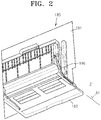
- FIG. 2 is a partial perspective view illustrating when a manual paper feed tray 182 of the cover opening and closing unit 180 of FIG. 1 is opened from a cover 181 of the cover opening and closing unit 180, according to an embodiment.
- FIG. 3 is a partial exploded view of the cover opening and closing unit 180 of FIG. 2 , according to an embodiment.
- FIG. 4 is a partial perspective view of a link element 190 illustrated in FIG. 3 , according to an embodiment.
- FIG. 5 is a partial perspective view of the manual paper feed tray 182 of FIG. 2 , according to an embodiment.
- the cover opening and closing unit 180 may be installed at a side of the main body 101.
- the cover opening and closing unit 180 may include the cover 181, the manual paper feed tray 182, the link element 190, and a connection link 196.
- the cover 181 may be rotatably installed on the main body 101 so as to be opened from and close a part of the main body 101.
- the cover 181 may be combined to the main body 101 so as to rotate with respect to a hinge part 1811.
- the manual paper feed tray 182 may be hinge-combined to the cover 181 to rotate to a closed position (refer to FIG. 1 ) and an opened position (refer to FIG. 2 ) having a first open angle (A1 in FIG. 2 ) with respect to a vertical direction (Z axis).
- the link element 190 may connect the cover 181 to the main body 101.
- the link element 190 may include a plurality of links that rotate with respect to each other when the cover 181 is opened from and closes the main body 101.
- the connection link 196 may connect the manual paper feed tray 182 to the link element 190, i.e., any one of the plurality of links.
- the connection link 196 may interact with a rotation of the link element 190 and maintain a second open angle (A2 in FIG. 6 ) of the manual paper feed tray 182 with respect to a vertical direction (Z axis) within an acute angle range, i.e., within 90 degrees.
- the manual paper feed tray 182 may include a paper support 183 on which paper is loaded, hinge holes 184 and 185 that are hinge-combined to the cover 181, and a guide rail 186 located on a side of the paper support 183.
- the link element 190 may be installed on a side of the cover 101.
- the link element 190 may include a cover-side main link 191, a main body-side main link 192, and a cover fixing link 193.
- a first end of the main body-side main link 192 may be rotatably connected to the cover-side main link 191 and a second end of the main body-side main link 192 may be rotatably connected to the main body 101.
- a first end of the cover fixing link 193 may be rotatably connected to the cover-side main link 191 and a second end of the cover fixing link 193 may be fixed on the cover 181 by, for example, a screw (not shown).
- the link element 190 may further include a first spring 194.
- the first spring 194 may apply an elastic force so that the main body-side main link 192 and the cover-side main link 191 rotate with respect to each other in a direction in which the main body-side main link 192 and the cover-side main link 191 are unfolded from each other.
- the first spring 194 may be a torsion spring that is installed in a connection portion between the cover-side main link 191 and the main body-side main link 192.
- the link member 190 may further include a second spring 195.
- the second spring 195 may apply an elastic force in a direction in which the cover-side main link 191 and the cover fixing link 193 are unfolded from each other.
- the second spring 195 may be a torsion spring that is installed in a connection portion between the cover-side main link 191 and the cover fixing link 193.
- connection link 196 may be connected to the cover-side main link 191 and the guide rail 186 of the manual paper feed tray 182.
- the cover-side main link 191 may include a connection part to which a first end of the connection link 196 may be rotatably connected.
- the connection part may include a protrusion 1911 protruding from the cover-side main link 191.
- a second end of the connection link 196 may include a guide protrusion 1961 that may be inserted into the guide rail 186 of the manual paper feed tray 182 to slide along the guide rail 186. As the guide protrusion 1961 slides along the guide rail 186, the manual paper feed tray 182 may rotate to a closed position and an opened position with respect to the cover 181.
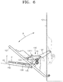
- FIG. 6 is a side view illustrating an operation of a cover opening and closing unit according to an embodiment.
- a view represented by a dashed line illustrates, as illustrated in FIG. 3 , when the cover 181 is attached to the main body 101 and the manual paper feed tray 182 is positioned in an opened position.
- the cover 181 is in a closed state, the cover-side main link 191 and the main body-side main link 192 of the link element 190 may be folded with each other as illustrated by dotted lines in FIGS. 3 and 6 .
- a guide protrusion 1961 that is arranged at an end of the connection link 196 may contact an end of the guide rail 186 of the manual paper feed tray 182, and thus the manual paper feed tray 182 may no longer rotate downward, and the first open angle A1 of the manual paper feed tray 182 with respect to a vertical direction (Z axis) may be maintained within 90 degrees. Therefore, sheets of paper P loaded on the manual paper feed tray 182 may not fall.
- the cover-side main link 191 and the main body-side main link 192 of the link element 190 may be unfolded from each other.
- the cover-side main link 191 may be moved more upward than the original position.
- the cover-side main link 191 and the main body-side main link 192 may be folded with each other and thus the protrusion 1911 may be positioned close to the cover 181.
- the cover-side main link 191 and the main body-side main link 192 may be unfolded from each other and thus the protrusion 1911 may be positioned away from the cover 181.
- the connection link 196 When the connection link 196 is connected to the protrusion 1911, the connection link 196 may be pulled toward the cover 181.
- the guide protrusion 1961 of the connection link 196 may contact the guide rail 186 of the manual paper feed tray 182 and thus, when the cover 181 is opened, the manual paper feed tray 182 may be pulled by the connection link 196 to rotate toward the cover 181.
- the second open angle A2 of the manual paper feed tray 182 may be maintained within 90° with respect to a vertical direction (Z axis) and sheets of paper P loaded on the manual paper feed tray 182 may not fall.
- An angle at which the cover 181 is opened with respect to the main body 101 may be determined by a degree to which an access to the inside of the main body 101 is possible through an opened space between the cover 181 and the main body 101.
- the angle may be set to be within about 50 degrees.
- the first and second open angles A1 and A2 of the manual paper feed tray 182 may be within 90 degrees, for example, 85 ⁇ 3 degrees.
- the image forming apparatus may be applied not only to an electrophotographic image forming apparatus but also to other image forming apparatuses, and the electrophotographic image forming apparatus may be used for colour printing or black and white printing.
- the scope of the invention is defined in the claims.
Landscapes
- Physics & Mathematics (AREA)
- General Physics & Mathematics (AREA)
- Electrophotography Configuration And Component (AREA)
- Manual Feeding Of Sheets (AREA)
- Accessory Devices And Overall Control Thereof (AREA)
Claims (11)
- Bilderzeugungsvorrichtung, die Folgendes umfasst:einen Hauptkörper (101);eine Abdeckung (181), die an einer lateralen Seite des Hauptkörpers (101) installiert ist, um von dem Hauptkörper (101) geöffnet zu werden und diesen zu schließen;ein manuelles Papierzufuhrfach (182) zum Aufnehmen von Papierbögen, wobei das manuelle Papierzufuhrfach (182) auf der Abdeckung (181) installiert ist, um sich zwischen einer geschlossenen Position und einer geöffneten Position zu drehen, wobei die geöffnete Position einen Öffnungswinkel in Bezug auf eine vertikale Richtung (Z) des Hauptkörpers (101) definiert;ein Gelenkgliedelement (190), das die Abdeckung (181) mit dem Hauptkörper (101) verbindet, wobei das Gelenkgliedelement (190) mehrere Gelenkglieder (191, 192, 193) umfasst, die drehbar verbunden sind, um sich in Bezug aufeinander zu drehen, wenn die Abdeckung (181) geöffnet oder geschlossen ist; undein Verbindungsgelenkglied (196), das ein erstes Ende, das mit dem Gelenkgliedelement (190) verbunden ist, und ein zweites Ende, das mit dem manuellen Papierzufuhrfach (182) verbunden ist, aufweist,wobei, wenn die Abdeckung (181) geöffnet ist und das manuelle Papierzufuhrfach (182) in der geöffneten Position positioniert ist, das Verbindungsgelenkglied (196) mit einer Drehung des Gelenkgliedelements (190) interagiert, um das manuelle Papierzufuhrfach (182) zu der Abdeckung (181) zu ziehen, um den Öffnungswinkel des manuellen Papiereinzugsfachs (182) innerhalb von 90 Grad in Bezug auf die vertikale Richtung zu halten,wobei die mehreren Gelenkglieder (191, 192, 193) ein abdeckungsseitiges Hauptgelenkglied (191), das mit der Abdeckung (181) drehbar verbunden ist, und ein hauptkörperseitiges Gelenkglied (192) umfassen, das ein erstes Ende, das mit dem abdeckungsseitigen Hauptgelenkglied (191) drehbar verbunden ist, und ein zweites Ende, das mit dem Hauptkörper (101) drehbar verbunden ist, aufweist, undwenn die Abdeckung (181) geöffnet ist, das hauptkörperseitige Gelenkglied (192) und das abdeckungsseitige Hauptgelenkglied (191) voneinander ausgeklappt sind.
- Bilderzeugungsvorrichtung nach Anspruch 1, die ferner eine Feder (194, 195) umfasst, die in Verbindungsteilen zwischen den mehreren Gelenkgliedern installiert ist.
- Bilderzeugungsvorrichtung nach Anspruch 2, wobei die Feder (194, 195) eine Torsionsfeder umfasst.
- Bilderzeugungsvorrichtung nach einem der vorhergehenden Ansprüche, wobei das erste Ende des Verbindungsgelenkglieds (196) mit dem abdeckungsseitigen Hauptgelenkglied (191) drehbar verbunden ist.
- Bilderzeugungsvorrichtung nach Anspruch 4, wobei das abdeckungsseitige Hauptgelenkglied (191) einen Vorsprung (1911) umfasst, mit dem das erste Ende des Verbindungsgelenkglieds (196) verbunden ist.
- Bilderzeugungsvorrichtung nach Anspruch 4, wenn abhängig von Anspruch 2, wobei die Feder (194, 195) eine erste Feder (194) umfasst, um eine elastische Kraft auf das hauptkörperseitige Hauptgelenkglied (192) und das abdeckungsseitige Hauptgelenkglied (191) in einer Richtung aufzubringen, in der das hauptkörperseitige Hauptgelenkglied (192) und das abdeckungsseitige Hauptgelenkglied (191) voneinander ausgeklappt sind.
- Bilderzeugungsvorrichtung nach Anspruch 6, wobei die mehreren Gelenkglieder ferner ein Abdeckungsbefestigungsgelenkglied (193) umfassen, das an der Abdeckung (181) befestigt ist und mit dem das abdeckungsseitige Hauptgelenkglied (191) drehbar verbunden ist,
die ferner eine zweite Feder (195) umfasst, um eine elastische Kraft auf das abdeckungsseitige Hauptgelenkglied (191) in einer Richtung aufzubringen, in der das abdeckungsseitige Hauptgelenkglied (191) aus dem Abdeckungsbefestigungsgelenklied (193) ausgeklappt ist. - Bilderzeugungsvorrichtung nach Anspruch 7, wobei die zweite Feder (195) eine Torsionsfeder umfasst.
- Bilderzeugungsvorrichtung nach einem der vorhergehenden Ansprüche, wobei der Öffnungswinkel 90 Grad oder weniger in Bezug auf die vertikale Richtung beträgt, unabhängig davon, ob die Abdeckung (181) geöffnet oder geschlossen ist.
- Bilderzeugungsvorrichtung nach Anspruch 9, wobei die Abdeckung (181) in einem Winkel von 50 Grad oder weniger in Bezug auf den Hauptkörper (101) geöffnet ist.
- Bilderzeugungsvorrichtung nach einem der vorhergehenden Ansprüche, die ferner Folgendes umfasst:wenigstens eine Entwicklungseinheit (120) zum Entwickeln eines elektrostatischen latenten Bilds; undeine Befestigungseinheit (160) zum Befestigen eines Tonerbilds, das durch die Entwicklungseinheit (120) auf Papier entwickelt wird.
Applications Claiming Priority (3)
| Application Number | Priority Date | Filing Date | Title |
|---|---|---|---|
| KR20110066443 | 2011-07-05 | ||
| KR1020110109434A KR101817698B1 (ko) | 2011-07-05 | 2011-10-25 | 커버개폐유닛 및 이를 구비하는 화상형성장치 |
| EP12159174.7A EP2544054B1 (de) | 2011-07-05 | 2012-03-13 | Deckelöffnungs- und -schließeinheit und Bilderzeugungsvorrichtung damit |
Related Parent Applications (2)
| Application Number | Title | Priority Date | Filing Date |
|---|---|---|---|
| EP12159174.7A Division EP2544054B1 (de) | 2011-07-05 | 2012-03-13 | Deckelöffnungs- und -schließeinheit und Bilderzeugungsvorrichtung damit |
| EP12159174.7A Division-Into EP2544054B1 (de) | 2011-07-05 | 2012-03-13 | Deckelöffnungs- und -schließeinheit und Bilderzeugungsvorrichtung damit |
Publications (2)
| Publication Number | Publication Date |
|---|---|
| EP3054355A1 EP3054355A1 (de) | 2016-08-10 |
| EP3054355B1 true EP3054355B1 (de) | 2021-11-17 |
Family
ID=45992035
Family Applications (2)
| Application Number | Title | Priority Date | Filing Date |
|---|---|---|---|
| EP16160879.9A Active EP3054355B1 (de) | 2011-07-05 | 2012-03-13 | Abdeckungsöffnungs- und -schliesseinheit und bilderzeugungsvorrichtung damit |
| EP12159174.7A Active EP2544054B1 (de) | 2011-07-05 | 2012-03-13 | Deckelöffnungs- und -schließeinheit und Bilderzeugungsvorrichtung damit |
Family Applications After (1)
| Application Number | Title | Priority Date | Filing Date |
|---|---|---|---|
| EP12159174.7A Active EP2544054B1 (de) | 2011-07-05 | 2012-03-13 | Deckelöffnungs- und -schließeinheit und Bilderzeugungsvorrichtung damit |
Country Status (6)
| Country | Link |
|---|---|
| US (2) | US8712312B2 (de) |
| EP (2) | EP3054355B1 (de) |
| KR (1) | KR101817698B1 (de) |
| CN (2) | CN103733139B (de) |
| TW (1) | TWI612001B (de) |
| WO (1) | WO2013005907A1 (de) |
Families Citing this family (34)
| Publication number | Priority date | Publication date | Assignee | Title |
|---|---|---|---|---|
| KR101817698B1 (ko) * | 2011-07-05 | 2018-01-16 | 에스프린팅솔루션 주식회사 | 커버개폐유닛 및 이를 구비하는 화상형성장치 |
| JP2014095813A (ja) * | 2012-11-09 | 2014-05-22 | Fuji Xerox Co Ltd | 装置 |
| JP6244629B2 (ja) * | 2013-01-30 | 2017-12-13 | 株式会社リコー | 手差し給紙装置および画像形成装置 |
| JP5810124B2 (ja) * | 2013-04-15 | 2015-11-11 | 京セラドキュメントソリューションズ株式会社 | 給紙装置、およびこれを備えた画像形成装置 |
| JP6116390B2 (ja) * | 2013-06-13 | 2017-04-19 | キヤノン株式会社 | 開閉機構及び画像形成装置 |
| JP2015028610A (ja) * | 2013-06-28 | 2015-02-12 | キヤノン株式会社 | 画像形成装置 |
| JP6126971B2 (ja) * | 2013-10-25 | 2017-05-10 | 株式会社沖データ | カバー開閉機構及び画像形成装置 |
| JP6135579B2 (ja) * | 2014-03-28 | 2017-05-31 | ブラザー工業株式会社 | 給紙装置 |
| JP6372169B2 (ja) * | 2014-05-30 | 2018-08-15 | ブラザー工業株式会社 | 画像形成装置 |
| JP6478667B2 (ja) * | 2014-12-26 | 2019-03-06 | キヤノン株式会社 | プリント装置 |
| JP6414474B2 (ja) * | 2015-01-27 | 2018-10-31 | ブラザー工業株式会社 | 画像形成装置 |
| JP6252516B2 (ja) | 2015-02-25 | 2017-12-27 | コニカミノルタ株式会社 | 給紙装置および画像形成装置 |
| JP6277996B2 (ja) * | 2015-05-15 | 2018-02-14 | 京セラドキュメントソリューションズ株式会社 | シート供給装置およびこれを備える画像形成装置 |
| JP6604088B2 (ja) * | 2015-08-20 | 2019-11-13 | 富士ゼロックス株式会社 | 画像形成装置 |
| JP6300769B2 (ja) * | 2015-08-21 | 2018-03-28 | キヤノン株式会社 | シート給送装置、および画像形成装置 |
| JP6704311B2 (ja) * | 2015-10-14 | 2020-06-03 | シャープ株式会社 | 画像形成装置及び給紙装置 |
| US10241464B2 (en) * | 2016-06-28 | 2019-03-26 | Fuji Xerox Co., Ltd. | Image forming apparatus having two opening and closing portions |
| JP6816532B2 (ja) * | 2017-01-26 | 2021-01-20 | ブラザー工業株式会社 | カバー開閉ストッパおよび画像形成装置 |
| JP6658614B2 (ja) * | 2017-02-28 | 2020-03-04 | 京セラドキュメントソリューションズ株式会社 | 画像形成装置 |
| CN108628117A (zh) * | 2017-03-16 | 2018-10-09 | 柯尼卡美能达办公系统研发(无锡)有限公司 | 图像形成装置 |
| JP6870519B2 (ja) * | 2017-07-25 | 2021-05-12 | ブラザー工業株式会社 | 画像形成装置 |
| WO2019027424A2 (en) * | 2017-07-31 | 2019-02-07 | Hewlett-Packard Development Company, L.P. | PLATE COVER EXTENSION DEVICES |
| US10173851B1 (en) * | 2017-09-20 | 2019-01-08 | Kabushiki Kaisha Toshiba | Sheet feed device and image forming apparatus |
| JP6500966B2 (ja) * | 2017-11-14 | 2019-04-17 | 株式会社リコー | 手差し給紙装置および画像形成装置 |
| JP6952596B2 (ja) * | 2017-12-20 | 2021-10-20 | 株式会社Pfu | 原稿搬送装置 |
| JP7098362B2 (ja) * | 2018-03-13 | 2022-07-11 | キヤノン株式会社 | シート給送装置及び画像形成装置 |
| JP7143656B2 (ja) * | 2018-07-13 | 2022-09-29 | ブラザー工業株式会社 | 印刷装置 |
| JP6680341B2 (ja) * | 2018-12-14 | 2020-04-15 | 株式会社リコー | 手差し給紙装置および画像形成装置 |
| JP7263858B2 (ja) * | 2019-03-14 | 2023-04-25 | 富士フイルムビジネスイノベーション株式会社 | 画像形成装置 |
| JP7392459B2 (ja) * | 2019-12-24 | 2023-12-06 | ブラザー工業株式会社 | 搬送装置 |
| JP7243804B2 (ja) * | 2020-03-16 | 2023-03-22 | 株式会社リコー | 手差し給紙装置および画像形成装置 |
| JP7067579B2 (ja) * | 2020-03-16 | 2022-05-16 | 株式会社リコー | 手差し給紙装置および画像形成装置 |
| JP2021178708A (ja) * | 2020-05-13 | 2021-11-18 | 東芝テック株式会社 | 画像処理装置 |
| KR102797701B1 (ko) * | 2023-08-21 | 2025-04-23 | 주식회사신도리코 | 프린터 수동 급지대의 급지 플레이트 로킹 장치 |
Citations (2)
| Publication number | Priority date | Publication date | Assignee | Title |
|---|---|---|---|---|
| JPH09190029A (ja) * | 1996-01-09 | 1997-07-22 | Canon Inc | 排紙装置及びこれを備える画像形成装置 |
| EP1577103A2 (de) * | 2004-03-08 | 2005-09-21 | Brother Kogyo Kabushiki Kaisha | Bilderzeugungsgerät |
Family Cites Families (15)
| Publication number | Priority date | Publication date | Assignee | Title |
|---|---|---|---|---|
| JP2003287973A (ja) * | 2002-03-28 | 2003-10-10 | Seiko Epson Corp | 画像形成装置 |
| US7099618B2 (en) * | 2002-10-01 | 2006-08-29 | Brother Kogyo Kabushiki Kaisha | Paper discharge tray |
| JP4803994B2 (ja) | 2004-11-12 | 2011-10-26 | キヤノン株式会社 | 画像形成装置 |
| JP4124772B2 (ja) * | 2005-02-14 | 2008-07-23 | シャープ株式会社 | 手差し給紙機構及び画像形成装置 |
| JP2006341987A (ja) * | 2005-06-10 | 2006-12-21 | Ricoh Co Ltd | 手差し給紙装置及び画像形成装置 |
| JP2007070044A (ja) * | 2005-09-07 | 2007-03-22 | Seiko Epson Corp | 画像形成装置 |
| JP4635951B2 (ja) * | 2006-04-27 | 2011-02-23 | 富士ゼロックス株式会社 | 画像形成装置 |
| JP4848258B2 (ja) * | 2006-12-05 | 2011-12-28 | 株式会社リコー | 画像形成装置 |
| EP1939695B1 (de) * | 2006-12-28 | 2015-07-29 | Brother Kogyo Kabushiki Kaisha | Bilderzeugungsvorrichtung mit der Fähigkeit zur präzisen Positionierung der Entwicklungseinheit und der Entwicklerkartusche |
| JP4905168B2 (ja) * | 2007-02-07 | 2012-03-28 | ブラザー工業株式会社 | 画像形成装置 |
| US7917057B2 (en) * | 2007-04-13 | 2011-03-29 | Kyocera Mita Corporation | Image forming apparatus with a front cover having a release member disposed to avoid incorrect operation |
| JP2010164773A (ja) * | 2009-01-15 | 2010-07-29 | Canon Inc | 画像形成装置 |
| JP5434307B2 (ja) | 2009-07-01 | 2014-03-05 | 村田機械株式会社 | 画像形成装置 |
| JP4930578B2 (ja) | 2009-12-03 | 2012-05-16 | ブラザー工業株式会社 | 画像形成装置 |
| KR101817698B1 (ko) * | 2011-07-05 | 2018-01-16 | 에스프린팅솔루션 주식회사 | 커버개폐유닛 및 이를 구비하는 화상형성장치 |
-
2011
- 2011-10-25 KR KR1020110109434A patent/KR101817698B1/ko not_active Expired - Fee Related
-
2012
- 2012-02-22 CN CN201280039627.7A patent/CN103733139B/zh active Active
- 2012-02-22 WO PCT/KR2012/001355 patent/WO2013005907A1/en not_active Ceased
- 2012-02-22 CN CN201610579795.5A patent/CN106019885B/zh active Active
- 2012-03-13 EP EP16160879.9A patent/EP3054355B1/de active Active
- 2012-03-13 EP EP12159174.7A patent/EP2544054B1/de active Active
- 2012-03-15 US US13/420,746 patent/US8712312B2/en active Active
- 2012-06-19 TW TW101121839A patent/TWI612001B/zh not_active IP Right Cessation
-
2014
- 2014-03-04 US US14/196,472 patent/US9188928B2/en active Active
Patent Citations (2)
| Publication number | Priority date | Publication date | Assignee | Title |
|---|---|---|---|---|
| JPH09190029A (ja) * | 1996-01-09 | 1997-07-22 | Canon Inc | 排紙装置及びこれを備える画像形成装置 |
| EP1577103A2 (de) * | 2004-03-08 | 2005-09-21 | Brother Kogyo Kabushiki Kaisha | Bilderzeugungsgerät |
Also Published As
| Publication number | Publication date |
|---|---|
| CN106019885A (zh) | 2016-10-12 |
| KR101817698B1 (ko) | 2018-01-16 |
| EP2544054B1 (de) | 2020-06-24 |
| EP2544054A1 (de) | 2013-01-09 |
| WO2013005907A1 (en) | 2013-01-10 |
| CN103733139B (zh) | 2016-08-24 |
| TW201302590A (zh) | 2013-01-16 |
| KR20130005206A (ko) | 2013-01-15 |
| EP3054355A1 (de) | 2016-08-10 |
| US8712312B2 (en) | 2014-04-29 |
| US20130011174A1 (en) | 2013-01-10 |
| US9188928B2 (en) | 2015-11-17 |
| TWI612001B (zh) | 2018-01-21 |
| CN103733139A (zh) | 2014-04-16 |
| US20140186083A1 (en) | 2014-07-03 |
| CN106019885B (zh) | 2018-12-14 |
Similar Documents
| Publication | Publication Date | Title |
|---|---|---|
| EP3054355B1 (de) | Abdeckungsöffnungs- und -schliesseinheit und bilderzeugungsvorrichtung damit | |
| CN101082794B (zh) | 图像形成设备 | |
| US8401426B2 (en) | Opening/closing mechanism and image forming apparatus | |
| US9417599B2 (en) | Image forming apparatus | |
| US7764905B2 (en) | Assist members for an openable structure of an image forming apparatus | |
| US20120177400A1 (en) | Process cartridge and image forming apparatus having the same | |
| CN112526856B (zh) | 盒和成像装置 | |
| US10754292B2 (en) | Image forming apparatus | |
| EP2597530B1 (de) | Bilderzeugungsvorrichtung | |
| US9563168B2 (en) | Image forming apparatus | |
| JP2005062326A (ja) | 画像形成装置 | |
| JP4078139B2 (ja) | 画像形成装置 | |
| US9008549B2 (en) | Compact image forming apparatus with simplified cover | |
| US7317885B2 (en) | Image forming apparatus mounted with an open and close unit | |
| JP7289725B2 (ja) | 開閉機構および画像形成装置 | |
| CN120704093A (zh) | 成像设备 | |
| JP4685196B2 (ja) | 画像形成装置 | |
| CN117130246A (zh) | 盒和成像装置 | |
| JP2021096421A (ja) | 光学ヘッド保持装置及び画像形成装置 | |
| JP2005266669A (ja) | 画像形成装置及びプロセスカートリッジの着脱方法 |
Legal Events
| Date | Code | Title | Description |
|---|---|---|---|
| PUAI | Public reference made under article 153(3) epc to a published international application that has entered the european phase |
Free format text: ORIGINAL CODE: 0009012 |
|
| 17P | Request for examination filed |
Effective date: 20160321 |
|
| AC | Divisional application: reference to earlier application |
Ref document number: 2544054 Country of ref document: EP Kind code of ref document: P |
|
| AK | Designated contracting states |
Kind code of ref document: A1 Designated state(s): AL AT BE BG CH CY CZ DE DK EE ES FI FR GB GR HR HU IE IS IT LI LT LU LV MC MK MT NL NO PL PT RO RS SE SI SK SM TR |
|
| RAP1 | Party data changed (applicant data changed or rights of an application transferred) |
Owner name: S-PRINTING SOLUTION CO., LTD. |
|
| RAP1 | Party data changed (applicant data changed or rights of an application transferred) |
Owner name: HP PRINTING KOREA CO., LTD. |
|
| RAP1 | Party data changed (applicant data changed or rights of an application transferred) |
Owner name: HEWLETT-PACKARD DEVELOPMENT COMPANY, L.P. |
|
| STAA | Information on the status of an ep patent application or granted ep patent |
Free format text: STATUS: EXAMINATION IS IN PROGRESS |
|
| 17Q | First examination report despatched |
Effective date: 20200528 |
|
| GRAP | Despatch of communication of intention to grant a patent |
Free format text: ORIGINAL CODE: EPIDOSNIGR1 |
|
| STAA | Information on the status of an ep patent application or granted ep patent |
Free format text: STATUS: GRANT OF PATENT IS INTENDED |
|
| INTG | Intention to grant announced |
Effective date: 20210824 |
|
| GRAS | Grant fee paid |
Free format text: ORIGINAL CODE: EPIDOSNIGR3 |
|
| GRAA | (expected) grant |
Free format text: ORIGINAL CODE: 0009210 |
|
| STAA | Information on the status of an ep patent application or granted ep patent |
Free format text: STATUS: THE PATENT HAS BEEN GRANTED |
|
| AC | Divisional application: reference to earlier application |
Ref document number: 2544054 Country of ref document: EP Kind code of ref document: P |
|
| AK | Designated contracting states |
Kind code of ref document: B1 Designated state(s): AL AT BE BG CH CY CZ DE DK EE ES FI FR GB GR HR HU IE IS IT LI LT LU LV MC MK MT NL NO PL PT RO RS SE SI SK SM TR |
|
| REG | Reference to a national code |
Ref country code: GB Ref legal event code: FG4D |
|
| REG | Reference to a national code |
Ref country code: IE Ref legal event code: FG4D |
|
| REG | Reference to a national code |
Ref country code: DE Ref legal event code: R096 Ref document number: 602012077199 Country of ref document: DE |
|
| REG | Reference to a national code |
Ref country code: AT Ref legal event code: REF Ref document number: 1448557 Country of ref document: AT Kind code of ref document: T Effective date: 20211215 |
|
| REG | Reference to a national code |
Ref country code: NL Ref legal event code: FP |
|
| REG | Reference to a national code |
Ref country code: LT Ref legal event code: MG9D |
|
| REG | Reference to a national code |
Ref country code: AT Ref legal event code: MK05 Ref document number: 1448557 Country of ref document: AT Kind code of ref document: T Effective date: 20211117 |
|
| PG25 | Lapsed in a contracting state [announced via postgrant information from national office to epo] |
Ref country code: RS Free format text: LAPSE BECAUSE OF FAILURE TO SUBMIT A TRANSLATION OF THE DESCRIPTION OR TO PAY THE FEE WITHIN THE PRESCRIBED TIME-LIMIT Effective date: 20211117 Ref country code: LT Free format text: LAPSE BECAUSE OF FAILURE TO SUBMIT A TRANSLATION OF THE DESCRIPTION OR TO PAY THE FEE WITHIN THE PRESCRIBED TIME-LIMIT Effective date: 20211117 Ref country code: FI Free format text: LAPSE BECAUSE OF FAILURE TO SUBMIT A TRANSLATION OF THE DESCRIPTION OR TO PAY THE FEE WITHIN THE PRESCRIBED TIME-LIMIT Effective date: 20211117 Ref country code: BG Free format text: LAPSE BECAUSE OF FAILURE TO SUBMIT A TRANSLATION OF THE DESCRIPTION OR TO PAY THE FEE WITHIN THE PRESCRIBED TIME-LIMIT Effective date: 20220217 Ref country code: AT Free format text: LAPSE BECAUSE OF FAILURE TO SUBMIT A TRANSLATION OF THE DESCRIPTION OR TO PAY THE FEE WITHIN THE PRESCRIBED TIME-LIMIT Effective date: 20211117 |
|
| PG25 | Lapsed in a contracting state [announced via postgrant information from national office to epo] |
Ref country code: IS Free format text: LAPSE BECAUSE OF FAILURE TO SUBMIT A TRANSLATION OF THE DESCRIPTION OR TO PAY THE FEE WITHIN THE PRESCRIBED TIME-LIMIT Effective date: 20220317 Ref country code: SE Free format text: LAPSE BECAUSE OF FAILURE TO SUBMIT A TRANSLATION OF THE DESCRIPTION OR TO PAY THE FEE WITHIN THE PRESCRIBED TIME-LIMIT Effective date: 20211117 Ref country code: PT Free format text: LAPSE BECAUSE OF FAILURE TO SUBMIT A TRANSLATION OF THE DESCRIPTION OR TO PAY THE FEE WITHIN THE PRESCRIBED TIME-LIMIT Effective date: 20220317 Ref country code: PL Free format text: LAPSE BECAUSE OF FAILURE TO SUBMIT A TRANSLATION OF THE DESCRIPTION OR TO PAY THE FEE WITHIN THE PRESCRIBED TIME-LIMIT Effective date: 20211117 Ref country code: NO Free format text: LAPSE BECAUSE OF FAILURE TO SUBMIT A TRANSLATION OF THE DESCRIPTION OR TO PAY THE FEE WITHIN THE PRESCRIBED TIME-LIMIT Effective date: 20220217 Ref country code: LV Free format text: LAPSE BECAUSE OF FAILURE TO SUBMIT A TRANSLATION OF THE DESCRIPTION OR TO PAY THE FEE WITHIN THE PRESCRIBED TIME-LIMIT Effective date: 20211117 Ref country code: HR Free format text: LAPSE BECAUSE OF FAILURE TO SUBMIT A TRANSLATION OF THE DESCRIPTION OR TO PAY THE FEE WITHIN THE PRESCRIBED TIME-LIMIT Effective date: 20211117 Ref country code: GR Free format text: LAPSE BECAUSE OF FAILURE TO SUBMIT A TRANSLATION OF THE DESCRIPTION OR TO PAY THE FEE WITHIN THE PRESCRIBED TIME-LIMIT Effective date: 20220218 Ref country code: ES Free format text: LAPSE BECAUSE OF FAILURE TO SUBMIT A TRANSLATION OF THE DESCRIPTION OR TO PAY THE FEE WITHIN THE PRESCRIBED TIME-LIMIT Effective date: 20211117 |
|
| PGFP | Annual fee paid to national office [announced via postgrant information from national office to epo] |
Ref country code: NL Payment date: 20220217 Year of fee payment: 11 Ref country code: FR Payment date: 20220218 Year of fee payment: 11 |
|
| PG25 | Lapsed in a contracting state [announced via postgrant information from national office to epo] |
Ref country code: SM Free format text: LAPSE BECAUSE OF FAILURE TO SUBMIT A TRANSLATION OF THE DESCRIPTION OR TO PAY THE FEE WITHIN THE PRESCRIBED TIME-LIMIT Effective date: 20211117 Ref country code: SK Free format text: LAPSE BECAUSE OF FAILURE TO SUBMIT A TRANSLATION OF THE DESCRIPTION OR TO PAY THE FEE WITHIN THE PRESCRIBED TIME-LIMIT Effective date: 20211117 Ref country code: RO Free format text: LAPSE BECAUSE OF FAILURE TO SUBMIT A TRANSLATION OF THE DESCRIPTION OR TO PAY THE FEE WITHIN THE PRESCRIBED TIME-LIMIT Effective date: 20211117 Ref country code: EE Free format text: LAPSE BECAUSE OF FAILURE TO SUBMIT A TRANSLATION OF THE DESCRIPTION OR TO PAY THE FEE WITHIN THE PRESCRIBED TIME-LIMIT Effective date: 20211117 Ref country code: DK Free format text: LAPSE BECAUSE OF FAILURE TO SUBMIT A TRANSLATION OF THE DESCRIPTION OR TO PAY THE FEE WITHIN THE PRESCRIBED TIME-LIMIT Effective date: 20211117 Ref country code: CZ Free format text: LAPSE BECAUSE OF FAILURE TO SUBMIT A TRANSLATION OF THE DESCRIPTION OR TO PAY THE FEE WITHIN THE PRESCRIBED TIME-LIMIT Effective date: 20211117 |
|
| REG | Reference to a national code |
Ref country code: DE Ref legal event code: R097 Ref document number: 602012077199 Country of ref document: DE |
|
| PLBE | No opposition filed within time limit |
Free format text: ORIGINAL CODE: 0009261 |
|
| STAA | Information on the status of an ep patent application or granted ep patent |
Free format text: STATUS: NO OPPOSITION FILED WITHIN TIME LIMIT |
|
| 26N | No opposition filed |
Effective date: 20220818 |
|
| PG25 | Lapsed in a contracting state [announced via postgrant information from national office to epo] |
Ref country code: MC Free format text: LAPSE BECAUSE OF FAILURE TO SUBMIT A TRANSLATION OF THE DESCRIPTION OR TO PAY THE FEE WITHIN THE PRESCRIBED TIME-LIMIT Effective date: 20211117 Ref country code: AL Free format text: LAPSE BECAUSE OF FAILURE TO SUBMIT A TRANSLATION OF THE DESCRIPTION OR TO PAY THE FEE WITHIN THE PRESCRIBED TIME-LIMIT Effective date: 20211117 |
|
| REG | Reference to a national code |
Ref country code: CH Ref legal event code: PL |
|
| GBPC | Gb: european patent ceased through non-payment of renewal fee |
Effective date: 20220313 |
|
| PG25 | Lapsed in a contracting state [announced via postgrant information from national office to epo] |
Ref country code: SI Free format text: LAPSE BECAUSE OF FAILURE TO SUBMIT A TRANSLATION OF THE DESCRIPTION OR TO PAY THE FEE WITHIN THE PRESCRIBED TIME-LIMIT Effective date: 20211117 |
|
| REG | Reference to a national code |
Ref country code: BE Ref legal event code: MM Effective date: 20220331 |
|
| PG25 | Lapsed in a contracting state [announced via postgrant information from national office to epo] |
Ref country code: LU Free format text: LAPSE BECAUSE OF NON-PAYMENT OF DUE FEES Effective date: 20220313 Ref country code: LI Free format text: LAPSE BECAUSE OF NON-PAYMENT OF DUE FEES Effective date: 20220331 Ref country code: IE Free format text: LAPSE BECAUSE OF NON-PAYMENT OF DUE FEES Effective date: 20220313 Ref country code: GB Free format text: LAPSE BECAUSE OF NON-PAYMENT OF DUE FEES Effective date: 20220313 Ref country code: CH Free format text: LAPSE BECAUSE OF NON-PAYMENT OF DUE FEES Effective date: 20220331 |
|
| PG25 | Lapsed in a contracting state [announced via postgrant information from national office to epo] |
Ref country code: BE Free format text: LAPSE BECAUSE OF NON-PAYMENT OF DUE FEES Effective date: 20220331 |
|
| PG25 | Lapsed in a contracting state [announced via postgrant information from national office to epo] |
Ref country code: IT Free format text: LAPSE BECAUSE OF FAILURE TO SUBMIT A TRANSLATION OF THE DESCRIPTION OR TO PAY THE FEE WITHIN THE PRESCRIBED TIME-LIMIT Effective date: 20211117 |
|
| REG | Reference to a national code |
Ref country code: NL Ref legal event code: MM Effective date: 20230401 |
|
| PG25 | Lapsed in a contracting state [announced via postgrant information from national office to epo] |
Ref country code: NL Free format text: LAPSE BECAUSE OF NON-PAYMENT OF DUE FEES Effective date: 20230401 |
|
| PG25 | Lapsed in a contracting state [announced via postgrant information from national office to epo] |
Ref country code: FR Free format text: LAPSE BECAUSE OF NON-PAYMENT OF DUE FEES Effective date: 20230331 |
|
| PG25 | Lapsed in a contracting state [announced via postgrant information from national office to epo] |
Ref country code: HU Free format text: LAPSE BECAUSE OF FAILURE TO SUBMIT A TRANSLATION OF THE DESCRIPTION OR TO PAY THE FEE WITHIN THE PRESCRIBED TIME-LIMIT; INVALID AB INITIO Effective date: 20120313 |
|
| PG25 | Lapsed in a contracting state [announced via postgrant information from national office to epo] |
Ref country code: MK Free format text: LAPSE BECAUSE OF FAILURE TO SUBMIT A TRANSLATION OF THE DESCRIPTION OR TO PAY THE FEE WITHIN THE PRESCRIBED TIME-LIMIT Effective date: 20211117 Ref country code: CY Free format text: LAPSE BECAUSE OF FAILURE TO SUBMIT A TRANSLATION OF THE DESCRIPTION OR TO PAY THE FEE WITHIN THE PRESCRIBED TIME-LIMIT Effective date: 20211117 |
|
| PG25 | Lapsed in a contracting state [announced via postgrant information from national office to epo] |
Ref country code: MT Free format text: LAPSE BECAUSE OF FAILURE TO SUBMIT A TRANSLATION OF THE DESCRIPTION OR TO PAY THE FEE WITHIN THE PRESCRIBED TIME-LIMIT Effective date: 20211117 |
|
| PGFP | Annual fee paid to national office [announced via postgrant information from national office to epo] |
Ref country code: DE Payment date: 20250218 Year of fee payment: 14 |
|
| REG | Reference to a national code |
Ref country code: DE Ref legal event code: R082 Ref document number: 602012077199 Country of ref document: DE Representative=s name: NOVAGRAAF BREVETS, FR |
|
| PG25 | Lapsed in a contracting state [announced via postgrant information from national office to epo] |
Ref country code: TR Free format text: LAPSE BECAUSE OF FAILURE TO SUBMIT A TRANSLATION OF THE DESCRIPTION OR TO PAY THE FEE WITHIN THE PRESCRIBED TIME-LIMIT Effective date: 20211117 |