EP3045333A2 - Lüftungsanordnung - Google Patents
Lüftungsanordnung Download PDFInfo
- Publication number
- EP3045333A2 EP3045333A2 EP16150805.6A EP16150805A EP3045333A2 EP 3045333 A2 EP3045333 A2 EP 3045333A2 EP 16150805 A EP16150805 A EP 16150805A EP 3045333 A2 EP3045333 A2 EP 3045333A2
- Authority
- EP
- European Patent Office
- Prior art keywords
- fin
- vehicle cabin
- register
- main body
- leading end
- Prior art date
- Legal status (The legal status is an assumption and is not a legal conclusion. Google has not performed a legal analysis and makes no representation as to the accuracy of the status listed.)
- Granted
Links
Images

Classifications
-
- B—PERFORMING OPERATIONS; TRANSPORTING
- B60—VEHICLES IN GENERAL
- B60H—ARRANGEMENTS OF HEATING, COOLING, VENTILATING OR OTHER AIR-TREATING DEVICES SPECIALLY ADAPTED FOR PASSENGER OR GOODS SPACES OF VEHICLES
- B60H1/00—Heating, cooling or ventilating [HVAC] devices
- B60H1/34—Nozzles; Air-diffusers
- B60H1/3414—Nozzles; Air-diffusers with means for adjusting the air stream direction
- B60H1/3421—Nozzles; Air-diffusers with means for adjusting the air stream direction using only pivoting shutters
-
- B—PERFORMING OPERATIONS; TRANSPORTING
- B60—VEHICLES IN GENERAL
- B60H—ARRANGEMENTS OF HEATING, COOLING, VENTILATING OR OTHER AIR-TREATING DEVICES SPECIALLY ADAPTED FOR PASSENGER OR GOODS SPACES OF VEHICLES
- B60H1/00—Heating, cooling or ventilating [HVAC] devices
- B60H1/34—Nozzles; Air-diffusers
- B60H1/3414—Nozzles; Air-diffusers with means for adjusting the air stream direction
-
- B—PERFORMING OPERATIONS; TRANSPORTING
- B60—VEHICLES IN GENERAL
- B60H—ARRANGEMENTS OF HEATING, COOLING, VENTILATING OR OTHER AIR-TREATING DEVICES SPECIALLY ADAPTED FOR PASSENGER OR GOODS SPACES OF VEHICLES
- B60H1/00—Heating, cooling or ventilating [HVAC] devices
- B60H1/00642—Control systems or circuits; Control members or indication devices for heating, cooling or ventilating devices
- B60H1/00664—Construction or arrangement of damper doors
-
- B—PERFORMING OPERATIONS; TRANSPORTING
- B60—VEHICLES IN GENERAL
- B60H—ARRANGEMENTS OF HEATING, COOLING, VENTILATING OR OTHER AIR-TREATING DEVICES SPECIALLY ADAPTED FOR PASSENGER OR GOODS SPACES OF VEHICLES
- B60H1/00—Heating, cooling or ventilating [HVAC] devices
- B60H1/00507—Details, e.g. mounting arrangements, desaeration devices
- B60H1/00557—Details of ducts or cables
- B60H1/00564—Details of ducts or cables of air ducts
-
- B—PERFORMING OPERATIONS; TRANSPORTING
- B60—VEHICLES IN GENERAL
- B60H—ARRANGEMENTS OF HEATING, COOLING, VENTILATING OR OTHER AIR-TREATING DEVICES SPECIALLY ADAPTED FOR PASSENGER OR GOODS SPACES OF VEHICLES
- B60H1/00—Heating, cooling or ventilating [HVAC] devices
- B60H1/00642—Control systems or circuits; Control members or indication devices for heating, cooling or ventilating devices
- B60H1/0065—Control members, e.g. levers or knobs
-
- B—PERFORMING OPERATIONS; TRANSPORTING
- B60—VEHICLES IN GENERAL
- B60H—ARRANGEMENTS OF HEATING, COOLING, VENTILATING OR OTHER AIR-TREATING DEVICES SPECIALLY ADAPTED FOR PASSENGER OR GOODS SPACES OF VEHICLES
- B60H1/00—Heating, cooling or ventilating [HVAC] devices
- B60H1/00642—Control systems or circuits; Control members or indication devices for heating, cooling or ventilating devices
- B60H1/00814—Control systems or circuits characterised by their output, for controlling particular components of the heating, cooling or ventilating installation
- B60H1/00821—Control systems or circuits characterised by their output, for controlling particular components of the heating, cooling or ventilating installation the components being ventilating, air admitting or air distributing devices
- B60H1/00871—Air directing means, e.g. blades in an air outlet
-
- B—PERFORMING OPERATIONS; TRANSPORTING
- B60—VEHICLES IN GENERAL
- B60H—ARRANGEMENTS OF HEATING, COOLING, VENTILATING OR OTHER AIR-TREATING DEVICES SPECIALLY ADAPTED FOR PASSENGER OR GOODS SPACES OF VEHICLES
- B60H1/00—Heating, cooling or ventilating [HVAC] devices
- B60H1/00642—Control systems or circuits; Control members or indication devices for heating, cooling or ventilating devices
- B60H1/00664—Construction or arrangement of damper doors
- B60H2001/00707—Details of pivots of damper doors
-
- B—PERFORMING OPERATIONS; TRANSPORTING
- B60—VEHICLES IN GENERAL
- B60H—ARRANGEMENTS OF HEATING, COOLING, VENTILATING OR OTHER AIR-TREATING DEVICES SPECIALLY ADAPTED FOR PASSENGER OR GOODS SPACES OF VEHICLES
- B60H1/00—Heating, cooling or ventilating [HVAC] devices
- B60H1/00642—Control systems or circuits; Control members or indication devices for heating, cooling or ventilating devices
- B60H1/00664—Construction or arrangement of damper doors
- B60H2001/00721—Air deflecting or air directing means
-
- B—PERFORMING OPERATIONS; TRANSPORTING
- B60—VEHICLES IN GENERAL
- B60H—ARRANGEMENTS OF HEATING, COOLING, VENTILATING OR OTHER AIR-TREATING DEVICES SPECIALLY ADAPTED FOR PASSENGER OR GOODS SPACES OF VEHICLES
- B60H1/00—Heating, cooling or ventilating [HVAC] devices
- B60H1/34—Nozzles; Air-diffusers
- B60H2001/3471—Details of actuators
Definitions
- the present invention relates to a register for use in a vehicle.
- Registers for use in a vehicle have structures in which an operation knob is attached to a fin, and the fin is inclined by manually pivoting the operation knob (for example, Japanese Utility Model Registration No. 3176607 , and Japanese Patent Application Laid-Open ( JP-A) No. 2011-148455 ).
- JP-A Japanese Patent Application Laid-Open
- a projection amount of the fin toward a vehicle cabin side with respect to a pivot axis of the fin that supports the operation knob is sometimes set short from the perspective of styling or the like (see, for example, JP-ANo. 2011-148455 ).
- an object of the present invention is to obtain a register capable of preventing or effectively suppressing damage to a fin during operation of an operation knob.
- a register of a first aspect of the present invention includes: a tube shaped retainer that is disposed in a register opening overlooking a vehicle cabin and that forms an air duct; a first fin that is axially supported at an inner side of the retainer so as to be capable of pivoting, and that is capable of being set in a standard orientation disposed along a tube axis of the retainer; a restricting mechanism that restricts a pivot range of the first fin; a second fin that includes a second fin main body that is disposed alongside and parallel to the first fin in a plate thickness direction of the first fin, that is capable of pivoting integrally with the first fin, and that, in a standard state in which the first fin is set in the standard orientation, has a leading end position at the vehicle cabin side of the second fin main body set further toward the vehicle cabin side than a leading end position at the vehicle cabin side of the first fin; an operation knob that is attached to an extension direction center portion of the first fin in a front view of the register, that extends out toward the vehicle cabin side
- the second fin includes the second fin main body that is disposed alongside and parallel to the first fin in the plate thickness direction of the first fin, and is capable of pivoting integrally with the first fin.
- the leading end position at the vehicle cabin side of the second fin main body is set further toward the vehicle cabin side than the leading end position at the vehicle cabin side of the first fin. This enables the first fin to be less noticeable in terms of styling.
- the operation knob is attached to the extension direction center portion of the first fin, and the operation knob extends out toward the vehicle cabin side. This enables the first fin and the second fin to be pivoted by operating the operation knob from the vehicle cabin side.
- the minimum gap between the location of the operation knob further to the vehicle cabin side than the pivot axis of the first fin and the second fin main body is set narrower than the minimum gap between the first fin and the second fin main body.
- the leading end position at the vehicle cabin side of the operation knob is set further toward the vehicle cabin side than the leading end position at the vehicle cabin side of the second fin main body.
- leading end at the vehicle cabin side of the operation knob and the leading end at the vehicle cabin side of the second fin main body are set such that the positions in a direction along the tube axis of the retainer are aligned with each other in the restricted state, in which the leading end at the vehicle cabin side of the operation knob has pivoted to the opposite side to the second fin main body side, and the first fin is restricted from pivoting by the restricting mechanism.
- the fingers of the operator contact the second fin main body, and so the fingers bounce off toward the vehicle cabin side.
- a situation in which the first fin in the restricted state, in which pivoting is restricted, is further pressed toward the side at which pivoting is restricted can be avoided, and so damage to the first fin is prevented or effectively suppressed.
- a register of a second aspect of the present invention has the configuration of the first aspect, wherein the second fin includes a pair of the second fin main bodies that are each respectively disposed alongside and parallel on either side of the first fin in the plate thickness direction of the first fin.
- the register of the present invention has an excellent advantageous effect of enabling damage to the fin during operation of the operation knob to be prevented or effectively suppressed.
- a register according to an exemplary embodiment of the present invention, with reference to Fig. 1 to Fig. 7 .
- the arrow FR indicates the vehicle front side
- the arrow UP indicates the vehicle upper side
- the arrow W indicates the vehicle width direction, as appropriate.
- simple reference to the up-down direction refers to up-down viewed from in front of the register
- simple reference to the left-right direction refers to left-right viewed from in front of the register.
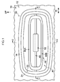
- Fig. 1 is a schematic front view illustrating a register 20 according to the present exemplary embodiment, in a state viewed from a vehicle cabin inside.
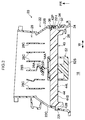
- Fig. 2 is a vertical cross-section in a state sectioned along line 2-2 in Fig. 1
- Fig. 3 is a horizontal cross-section sectioned along line 3-3 in Fig. 1 .
- Fig. 1 illustrates a portion at a location at the vehicle width direction outside of a vehicle cabin front section 10, and the register 20 described in the present exemplary embodiment configures a side register.
- an instrument panel 12 is disposed in the vehicle cabin front section 10.
- An air conditioning unit (not illustrated in the drawings) is disposed at the vehicle front side of the instrument panel 12 (the far side of the page in Fig. 1 ).
- a register opening 14 that overlooks a vehicle cabin 16 is formed piercing through the instrument panel 12.
- the register opening 14 is set with a longer length along the vehicle width direction than along the vehicle up-down direction.
- the register 20 is disposed in the register opening 14.
- the register 20 is connected to a main body section of the air conditioning unit, configures a location that blows out air that is temperature-adjusted by the main body section of the air conditioning unit, and has a flow direction adjustment function capable of distributing airflow inside the vehicle cabin.
- the register 20 is provided with a tube shaped retainer 22 that is disposed in the register opening 14 and forms an air duct.
- a direction running along a tube axis 22X of the retainer 22 is set along the vehicle front-rear direction.
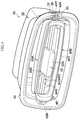
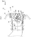
- Fig. 4 is a schematic perspective view illustrating the register 20
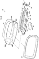
- Fig. 5 is a schematic exploded perspective view illustrating part of the register 20.
- the retainer 22 is formed in a substantially rectangular tube shape in a front view of the register, and is set with a longer length along the vehicle width direction than along the vehicle up-down direction.
- a bezel 24 is attached to an open end portion 22A (see Fig. 5 ) at the vehicle cabin side of the retainer 22.
- Plural attaching tabs are formed at intervals along the vehicle width direction at an upper portion and a lower portion of the bezel 24.
- the attaching tabs are attached to attachment portions, not illustrated in the drawings, formed to the open end portion 22A at the vehicle cabin side of the retainer 22.
- the open end portion 22A and the bezel 24 at the vehicle cabin 16 side of the retainer 22 are disposed adjacent to the register opening 14.
- a downstream side flow direction adjuster 26 is provided at the inner side and air duct downstream side of the retainer 22.
- the downstream side flow direction adjuster 26, described in detail later, is configured including a flow direction adjustment member 40 and an operation knob 52.
- An upstream side flow direction adjuster 28 is provided at the inner side and air duct upstream side of the retainer 22.
- the upstream side flow direction adjuster 28 has a known configuration and so detailed explanation is omitted.
- plural upright fins 28B, 28C are axially supported by the retainer 22 so as to be capable of pivoting.
- a cutout portion 22H is formed at a vehicle cabin side end portion of an up-down direction intermediate portion of a side wall portion 22B at the right side of the retainer 22, and a plate 32 is attached so as to block a portion of the cutout portion 22H.
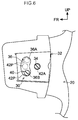
- Fig. 6 is a drawing illustrating an enlarged state of part of a side portion at the right side of the register 20 including the plate 32, as viewed from the vehicle width direction inside of the register.
- a shaft bearing portion 34 is formed to the plate 32, and a guide hole 36 is formed piercing through the plate 32 at the opposite side of the shaft bearing portion 34 to the vehicle cabin side.
- the guide hole 36 is formed in a circular arc shape about the shaft bearing portion 34.
- a shaft bearing portion 221 is formed to a side wall portion 22C at the left side of the retainer 22.
- the shaft bearing portion 221 is a portion set facing the shaft bearing portion 34 previously described.
- a shaft 42A formed projecting out from a right side end portion of the flow direction adjustment member 40 is axially supported by the shaft bearing portion 34 of the plate 32 so as to be capable of rotating
- a shaft 42B formed projecting out from a left side end portion of the flow direction adjustment member 40 is axially supported by the shaft bearing portion 221 of the retainer 22 so as to be capable of rotating.
- a stopper pin 42P formed projecting out from the right side end portion of the flow direction adjustment member 40 is inserted through the guide hole 36 of the plate 32 so as to be capable of moving.
- a first fin 44 disposed with its length direction along the vehicle left-right direction, is formed to the flow direction adjustment member 40.
- the above-described shafts 42A, 42B are integrally formed at each end portion side of the first fin 44 in front view.
- the first fin 44 is thereby axially supported so as to be capable of pivoting at the inner side of the retainer 22.
- the first fin 44 is capable of being set in a standard orientation 44X disposed along the tube axis 22X of the retainer 22 (the orientation illustrated in Fig. 2 ).
- the above-described stopper pin 42P is integrally set in the flow direction adjustment member 40 at the right side end portion side of the first fin 44.
- the stopper pin 42P is set at the opposite side of the shaft 42A to the vehicle cabin side.
- Downward pivoting of the first fin 44 is restricted by the stopper pin 42P abutting an inner peripheral upper end face 36A of the guide hole 36 (see Fig. 6 )
- upward pivoting of the first fin 44 is restricted by the stopper pin 42P abutting an inner peripheral lower end face 36B of the guide hole 36 (see Fig. 6 ).
- the stopper pin 42P, together with the inner peripheral upper end face 36A and the inner peripheral lower end face 36B of the guide hole 36 configure a restricting mechanism 30 that restricts the pivot range of the first fin 44.
- the flow direction adjustment member 40 is also provided with a second fin 46 at the outer peripheral side of the first fin 44.
- the respective plate thicknesses of the first fin 44 and the second fin 46 may be set as appropriate, and the first fin 44 is preferably set thinner than the plate thickness of the second fin 46 from the perspective of styling.
- the second fin 46 is formed in a short tube shape that has a substantially rectangular shape with rounded corners (or a substantially oval shape) in a front view of the register, and is set with a longer length along the vehicle width direction than along the vehicle up-down direction.
- the respective length direction end portions of the first fin 44 are integrally connected to respective inner face sides at up-down direction intermediate portions of side portions 48A, 48B configuring respective left and right sides of the second fin 46.
- Outer face sides at the up-down direction intermediate portions of the side portions 48A, 48B are integrally connected to the shafts 42A, 42B.
- the second fin 46 is thereby capable of pivoting integrally with the first fin 44.
- the stopper pin 42P is integrally connected to the outer face side at the up-down direction intermediate portion of the side portion 48A configuring the right side of the second fin 46.
- the second fin 46 is provided with a pair of second fin main bodies 50A, 50B that are each respectively disposed alongside and parallel to either side of the first fin 44 in the plate thickness direction of the first fin 44.
- positions of leading ends 50S, 50T at the vehicle cabin side of the second fin main bodies 50A, 50B of the second fin 46 are set further toward the vehicle cabin 16 side (vehicle rear side) than a position of a leading end 44S at the vehicle cabin side of the first fin 44.
- the operation knob 52 is attached to an extension direction center portion of the first fin 44 of the flow direction adjustment member 40 in a front view of the register. Although the operation knob 52 is capable of sliding along the vehicle width direction, a slide range of the operation knob 52 is within a relatively small range at the extension direction center portion of the first fin 44.
- a rack 54A is integrally provided to a vehicle front side of the operation knob 52.
- the rack 54A is disposed such that plural teeth, further to the vehicle front side than the first fin 44, are oriented toward the vehicle front side in a row along the vehicle width direction.
- a fan-shaped gear wheel 28A is enmeshed with the rack 54A.
- the fan shaped gear wheel 28A is provided to the upright fin 28B configuring the upstream side flow direction adjuster 28.
- the upright fins 28C disposed alongside either side of the upright fin 28B are coupled to the upright fin 28B by a coupling mechanism, not illustrated in the drawings.
- a minimum gap between a location 52A further to the vehicle cabin 16 side than a pivot axis 44L of the first fin 44, and the second fin main bodies 50A, 50B is set narrower (specifically, at a dimension at which the fingers of an operator do not enter) than a minimum gap between the first fin 44 and the second fin main bodies 50A, 50B.
- the position of a leading end 52S at the vehicle cabin side is set further to the vehicle cabin 16 side (vehicle rear side) than the positions of the leading ends 50S, 50T at the vehicle cabin side of the second fin main bodies 50A, 50B.
- the leading end 52S at the vehicle cabin side of the operation knob 52, and the leading end 50S at the vehicle cabin side of the second fin main body 50A at the upper side of the leading end 52S are set such that vehicle front-rear direction positions (positions in a direction running along the tube axis 22X of the retainer 22) are aligned with each other in a restricted state, in which the leading end 52S at the vehicle cabin side of the operation knob 52 has pivoted to the opposite side to the second fin main body 50A side, and the first fin 44 is restricted from pivoting by the restricting mechanism 30 (see Fig. 6 ) (see the straight line L running along the vehicle up-down direction).
- the leading end 52S at the vehicle cabin side of the operation knob 52 illustrated in Fig. 2 , and the leading end 50T at the vehicle cabin side of the second fin main body 50B at the lower side of the leading end 52S are set such that vehicle front-rear direction positions (positions in a direction running along the tube axis 22X of the retainer 22) are aligned with each other in a restricted state, in which the leading end 52S at the vehicle cabin side of the operation knob 52 has pivoted to the opposite side to the second fin main body 50B side (namely, the upper side), and the first fin 44 is restricted from pivoting by the restricting mechanism 30 (see Fig. 6 ).
- the second fin 46 is provided with the second fin main bodies 50A, 50B that are disposed alongside and parallel to the first fin 44 in the plate thickness direction of the first fin 44, and is capable of pivoting integrally with the first fin 44.
- the positions of the leading ends 50S, 50T at the vehicle cabin side of the second fin main bodies 50A, 50B are set further toward the vehicle cabin 16 side than the position of the leading end 44S at the vehicle cabin side of the first fin 44. This enables the first fin 44 to be less noticeable in terms of styling.
- the operation knob 52 is attached to the extension direction center portion of the first fin 44, and the operation knob 52 extends out toward the vehicle cabin 16 side. This enables the first fin 44 and the second fin 46 to be pivoted by operating the operation knob 52 from the vehicle cabin 16 side.
- the minimum gap between the location 52A further to the vehicle cabin side than the pivot axis 44L of the first fin 44, and the second fin main bodies 50A, 50B is set narrower than the minimum gap between the first fin 44 and the second fin main bodies 50A, 50B.
- the fingers of the operator are less liable to enter between the extension direction center portion of the first fin 44 and the second fin main bodies 50A, 50B.
- this prevents or effectively suppresses pressing at the extension direction center portion of the first fin 44 toward the vicinity of the pivot axis 44L. This accordingly prevents or effectively suppresses damage to the first fin 44 caused by such pressing.
- locations at the side direction sides of the operation knob 52 of the first fin 44 illustrated in Fig. 1 are less liable to deform than the extension direction center portion of the first fin 44, and design in order to secure rigidity is easier. Thus, even supposing that the fingers of the operator enter between the first fin 44 at the side direction sides of the operation knob 52 and the second fin main bodies 50A, 50B and operating force acts on the first fin 44, the first fin 44 is not easily damaged.
- the position of the leading end 52S at the vehicle cabin side of the operation knob 52 is set further to the vehicle cabin 16 side than the positions of the leading ends 50S, 50T at the vehicle cabin side of the second fin main bodies 50A, 50B.
- the gap between the location 52A at the vehicle cabin side of the operation knob 52 and the second fin main bodies 50A, 50B is narrower than the pivot axis 44L of the first fin 44 as described above, the operator can easily finger-operate a leading end portion at the vehicle cabin side of the operation knob 52 in the standard state.
- the leading end 52S at the vehicle cabin side of the operation knob 52, and the leading end 50S at the vehicle cabin side of the second fin main body 50A at the upper side of the leading end 52S are set such that the vehicle front-rear direction positions (positions in a direction running along the tube axis 22X of the retainer 22) are aligned with each other in the restricted state, in which the leading end 52S at the vehicle cabin side of the operation knob 52 has pivoted to the opposite side to the second fin main body 50A side (namely, the lower side), and the first fin 44 is restricted from pivoting by the restricting mechanism 30 (see Fig. 6 ) (see the double-dotted dashed line L).
- the fingers of the operator contact the leading end 50S at the vehicle cabin side of the second fin main body 50A, or a portion in the vicinity thereof, and so the fingers bounce off toward the vehicle cabin 16 side.
- a situation in which the first fin 44 in the restricted state, in which pivoting toward the lower side is restricted, is further pressed toward the lower side can be avoided, and so damage to the first fin 44 is prevented or effectively suppressed.
- leading end 52S at the vehicle cabin side of the operation knob 52 illustrated in Fig. 2 and the leading end 50T at the vehicle cabin side of the second fin main body 50B at the lower side of the leading end 52S are set such that vehicle front-rear direction positions (positions in a direction running along the tube axis 22X of the retainer 22) are aligned with each other in the restricted state, in which the leading end 52S at the vehicle cabin side of the operation knob 52 has pivoted to the opposite side to the second fin main body 50B side (namely, the upper side), and the first fin 44 is restricted from pivoting by the restricting mechanism 30 (see Fig. 6 ).
- the fingers of the operator contact the leading end 50T at the vehicle cabin side of the second fin main body 50B, or a portion in the vicinity thereof, and so the fingers bounce off toward the vehicle cabin 16 side.
- a situation in which the first fin 44, in the restricted state in which pivoting toward the upper side is restricted is further pressed toward the upper side can be avoided, and so damage to the first fin 44 is prevented or effectively suppressed.
- the register of the present invention enables damage to the first fin 44 during operation of the operation knob 52 to be prevented or effectively suppressed.
- the length direction center portion of the first fin 44 is essentially not pressed downward or pressed upward due to the above-described operation, thereby enabling damage to the first fin 44 to be prevented or effectively suppressed.
- the register 20 is configured as a side register; however, the register applied with the present invention may, for example, be a register such as a side register disposed at another location of the vehicle cabin front section, or disposed at a location other than the vehicle cabin front section, such as a vehicle cabin rear section.
- first fin 44 and the second fin main bodies 50A, 50B are disposed so as to extend along the lateral direction in a front view of the register; however, as a modified example of the above exemplary embodiment, a first fin and a second fin main body may be disposed so as to extend along the vertical direction in a front view of the register.
- the second fin 46 is provided with the pair of second fin main bodies 50A, 50B that are each respectively disposed alongside and parallel to either side of the first fin 44 in the plate thickness direction of the first fin 44; however, a second fin may be configured provided with a single second fin main body disposed alongside and parallel to a first fin in the plate thickness direction of the first fin.
- a configuration may be applied in which the position of a lower wall portion of a retainer (22) is set at the position of the second fin main body 50B in Fig. 2 , and a second fin is formed with locations of the second fin 46 of the above exemplary embodiment removed that are further to the lower side than the first fin 44.
- a configuration may be applied in which the position of an upper wall portion of a retainer (22) is set at the position of the second fin main body 50A in Fig. 2 , and a second fin is formed with locations of the second fin 46 of the above exemplary embodiment removed that are further to the upper side than the first fin 44.
- positions in a direction along the tube axis of the retainer are aligned with each other includes cases in which the positions are completely aligned with each other in the direction running along the tube axis of the retainer.
- the concept also includes cases in which, as in the above exemplary embodiment, although the positions cannot be said to be completely aligned with each other in the direction running along the tube axis of the retainer, basically the same operation and advantageous effects can be obtained as when the positions are completely aligned with each other, and the positions may be considered as substantially aligned with each other in the direction running along the tube axis of the retainer.
Landscapes
- Physics & Mathematics (AREA)
- Thermal Sciences (AREA)
- Engineering & Computer Science (AREA)
- Mechanical Engineering (AREA)
- Air-Conditioning For Vehicles (AREA)
- Air-Flow Control Members (AREA)
- Mechanical Control Devices (AREA)
Applications Claiming Priority (1)
| Application Number | Priority Date | Filing Date | Title |
|---|---|---|---|
| JP2015004383A JP6260543B2 (ja) | 2015-01-13 | 2015-01-13 | レジスタ |
Publications (3)
| Publication Number | Publication Date |
|---|---|
| EP3045333A2 true EP3045333A2 (de) | 2016-07-20 |
| EP3045333A3 EP3045333A3 (de) | 2016-11-30 |
| EP3045333B1 EP3045333B1 (de) | 2020-01-01 |
Family
ID=55085595
Family Applications (1)
| Application Number | Title | Priority Date | Filing Date |
|---|---|---|---|
| EP16150805.6A Active EP3045333B1 (de) | 2015-01-13 | 2016-01-11 | Lüftungsanordnung |
Country Status (5)
| Country | Link |
|---|---|
| US (1) | US10792976B2 (de) |
| EP (1) | EP3045333B1 (de) |
| JP (1) | JP6260543B2 (de) |
| CN (1) | CN105774475B (de) |
| AU (1) | AU2016200118B2 (de) |
Families Citing this family (12)
| Publication number | Priority date | Publication date | Assignee | Title |
|---|---|---|---|---|
| DE102016108356A1 (de) * | 2016-05-04 | 2017-11-09 | Illinois Tool Works Inc. | Luftausströmer für ein Kraftfahrzeug |
| CN107160971B (zh) * | 2017-06-08 | 2020-05-12 | 芜湖艾卡汽车技术有限公司 | 一种去除汽车窗雾气装置 |
| JP7013149B2 (ja) * | 2017-06-30 | 2022-01-31 | 豊和化成株式会社 | レジスタ |
| CN107962932B (zh) * | 2017-11-14 | 2020-01-14 | 江苏菲尔诺车业有限公司 | 一种汽车装饰用空调口空气清新剂夹 |
| JP6893481B2 (ja) * | 2018-01-24 | 2021-06-23 | 株式会社豊田自動織機 | レジスタ |
| JP7372742B2 (ja) * | 2019-01-25 | 2023-11-01 | 豊和化成株式会社 | レジスタ |
| JP6909906B1 (ja) * | 2020-07-09 | 2021-07-28 | マレリ株式会社 | ベンチレータ |
| USD965754S1 (en) * | 2020-12-09 | 2022-10-04 | Classic Auto Air Manufacturing LP | Vent for vehicle heating and air conditioning systems |
| EP4279302A4 (de) * | 2021-01-13 | 2024-11-13 | Zhejiang Geely Holding Group Co., Ltd. | Luftauslassanordnung und fahrzeug |
| JP7489935B2 (ja) | 2021-03-03 | 2024-05-24 | 株式会社豊田自動織機 | レジスタ |
| CN113619358B (zh) * | 2021-08-16 | 2023-04-25 | 诺博汽车系统有限公司 | 一种用于车辆的出风组件和具有其的车辆 |
| JP7785425B2 (ja) * | 2021-11-02 | 2025-12-15 | しげる工業株式会社 | 車両用レジスタ装置 |
Citations (2)
| Publication number | Priority date | Publication date | Assignee | Title |
|---|---|---|---|---|
| JP2011148455A (ja) | 2010-01-22 | 2011-08-04 | Howa Kasei Kk | レジスタ |
| JP3176607U (ja) | 2012-04-02 | 2012-06-28 | 豊和化成株式会社 | レジスタの操作ノブ装置 |
Family Cites Families (38)
| Publication number | Priority date | Publication date | Assignee | Title |
|---|---|---|---|---|
| US3552295A (en) * | 1969-02-13 | 1971-01-05 | Gen Motors Corp | Air conditioner grill having pivoting horizontal and vertical louvers |
| US3662668A (en) * | 1970-08-24 | 1972-05-16 | Randall W Johnson | Bezel inner guide frame |
| US3701311A (en) * | 1970-12-07 | 1972-10-31 | Cary Products Inc | Louver construction |
| US4653386A (en) * | 1984-11-20 | 1987-03-31 | Toyota Jidosha Kabushiki Kaisha | Wind direction adjusting mechanism for air conditioner |
| SE461997B (sv) * | 1987-11-17 | 1990-04-23 | Saab Scania Ab | Arrangemang foer roerelseoeverfoering i ett fordons ventilationssystem |
| JP2547279B2 (ja) * | 1989-12-15 | 1996-10-23 | 株式会社マスダハーモ | 空気循環装置 |
| JPH0789338A (ja) * | 1993-09-21 | 1995-04-04 | Suzuki Motor Corp | 自動車用空調装置の空気吹出口構造 |
| JP3298749B2 (ja) * | 1994-09-14 | 2002-07-08 | 関東自動車工業株式会社 | 自動車用レジスタ |
| DE4433698C1 (de) * | 1994-09-21 | 1995-12-14 | Siemens Ag | Luftverteilungsvorrichtung |
| AUPN164695A0 (en) * | 1995-03-10 | 1995-04-06 | Luminis Pty Limited | Improved induction nozzle and arrangement |
| US5921860A (en) * | 1996-04-01 | 1999-07-13 | Bowles Fluidics Corporation | Vehicle air outlet with uniform precision feel to operator |
| JP3913334B2 (ja) * | 1996-11-20 | 2007-05-09 | 三菱電機株式会社 | 換気送風装置および換気送風システム |
| JP3605577B2 (ja) * | 2001-05-15 | 2004-12-22 | 本田技研工業株式会社 | 空調用吹出口装置 |
| US6736719B1 (en) * | 2002-11-08 | 2004-05-18 | Collins & Aikman Products Co. | Air duct outlet with joystick louver control |
| JP3971991B2 (ja) * | 2002-12-03 | 2007-09-05 | 株式会社日立産機システム | エアシャワ装置 |
| US20060052050A1 (en) * | 2004-09-09 | 2006-03-09 | Dometic Corporation | Air distribution apparatus |
| CA2484305A1 (en) * | 2004-10-08 | 2006-04-08 | Progressive Moulded Products Limited | Control wheel |
| JP4890203B2 (ja) * | 2006-11-20 | 2012-03-07 | 豊和化成株式会社 | 車室内用空気吹出装置 |
| JP4980812B2 (ja) | 2007-07-23 | 2012-07-18 | 本田技研工業株式会社 | 車両のエアダンパ装置 |
| JP4371326B2 (ja) * | 2007-10-16 | 2009-11-25 | 森六テクノロジー株式会社 | 空調用吹出口の送風方向変更装置 |
| US8113229B2 (en) * | 2008-07-24 | 2012-02-14 | Honda Motor Co., Ltd. | Gear operated shut valve for a ventilation system |
| US20100124876A1 (en) * | 2008-11-20 | 2010-05-20 | Edilbert Yu | Air duct outlet |
| FR2956065B1 (fr) * | 2010-02-10 | 2012-04-20 | Faurecia Interieur Ind | Dispositif de sortie d'air pour planche de bord de vehicule automobile |
| JP5223124B2 (ja) * | 2010-03-25 | 2013-06-26 | 豊田合成株式会社 | 空調用レジスタ |
| JP5632992B2 (ja) * | 2010-11-22 | 2014-12-03 | 日本電子株式会社 | ターボ分子ポンプの接続装置 |
| JP5763449B2 (ja) * | 2011-06-30 | 2015-08-12 | 本田技研工業株式会社 | 排気浄化システム |
| GB2494421A (en) * | 2011-09-07 | 2013-03-13 | Jaguar Cars | Retractable vent deployable dependant on air demand |
| JP2013112256A (ja) | 2011-11-30 | 2013-06-10 | Toyoda Gosei Co Ltd | 空調用レジスタ |
| JP5724852B2 (ja) | 2011-11-30 | 2015-05-27 | 豊田合成株式会社 | 空調用レジスタ |
| KR101316488B1 (ko) * | 2011-12-23 | 2013-10-08 | 현대자동차주식회사 | 에어벤트 윙노브 조절장치 |
| KR101929554B1 (ko) * | 2012-05-21 | 2018-12-17 | 현대모비스 주식회사 | 차량의 에어 벤트 조립체 |
| JP6086669B2 (ja) * | 2012-08-01 | 2017-03-01 | 豊和化成株式会社 | レジスタ |
| JP5958438B2 (ja) * | 2012-10-30 | 2016-08-02 | 豊田合成株式会社 | 空調用レジスタ |
| FR3004997B1 (fr) | 2013-04-26 | 2016-03-11 | Renault Sas | Aerateur de ventilation d'un vehicule automobile |
| KR102078983B1 (ko) * | 2013-07-24 | 2020-02-19 | 현대모비스 주식회사 | 댐퍼 유닛 및 이를 이용한 차량용 에어벤트 |
| JP5892127B2 (ja) * | 2013-08-28 | 2016-03-23 | 豊田合成株式会社 | 空調用レジスタ |
| KR20150068900A (ko) * | 2013-12-12 | 2015-06-22 | 가부시키가이샤 니프코 | 풍향조정장치 |
| DE102017103760A1 (de) * | 2017-02-23 | 2018-08-23 | Dr. Schneider Kunststoffwerke Gmbh | Luftausströmer |
-
2015
- 2015-01-13 JP JP2015004383A patent/JP6260543B2/ja not_active Expired - Fee Related
-
2016
- 2016-01-06 US US14/989,481 patent/US10792976B2/en not_active Expired - Fee Related
- 2016-01-06 CN CN201610008543.7A patent/CN105774475B/zh not_active Expired - Fee Related
- 2016-01-08 AU AU2016200118A patent/AU2016200118B2/en not_active Ceased
- 2016-01-11 EP EP16150805.6A patent/EP3045333B1/de active Active
Patent Citations (2)
| Publication number | Priority date | Publication date | Assignee | Title |
|---|---|---|---|---|
| JP2011148455A (ja) | 2010-01-22 | 2011-08-04 | Howa Kasei Kk | レジスタ |
| JP3176607U (ja) | 2012-04-02 | 2012-06-28 | 豊和化成株式会社 | レジスタの操作ノブ装置 |
Also Published As
| Publication number | Publication date |
|---|---|
| EP3045333B1 (de) | 2020-01-01 |
| JP2016130067A (ja) | 2016-07-21 |
| US10792976B2 (en) | 2020-10-06 |
| US20160200167A1 (en) | 2016-07-14 |
| JP6260543B2 (ja) | 2018-01-17 |
| AU2016200118B2 (en) | 2018-03-15 |
| CN105774475B (zh) | 2018-05-01 |
| EP3045333A3 (de) | 2016-11-30 |
| AU2016200118A1 (en) | 2016-07-28 |
| CN105774475A (zh) | 2016-07-20 |
Similar Documents
| Publication | Publication Date | Title |
|---|---|---|
| EP3045333A2 (de) | Lüftungsanordnung | |
| US9989275B2 (en) | Register | |
| US9162551B2 (en) | Register | |
| US9879877B2 (en) | Air conditioning register | |
| US10328774B2 (en) | Vane adjustment device for an air register and an air register assembly | |
| JP2002337544A (ja) | 空調用吹出口装置 | |
| CN105091288A (zh) | 空调调风器 | |
| EP2009332A2 (de) | Dichtungselement | |
| US11987100B2 (en) | Fluid discharge device | |
| CN104114389B (zh) | 车辆空调装置 | |
| JP2017087760A (ja) | 空調用薄型レジスタ | |
| US20190061476A1 (en) | Low-profile air-conditioning register | |
| US7350855B2 (en) | Vehicle water drainage structure | |
| JP6424723B2 (ja) | 空調用レジスタ | |
| EP3173269A1 (de) | Innenraumlüfter für ein fahrzeug und verfahren zur montage eines innenraumlüfters | |
| JP6883452B2 (ja) | 車両用空気吹出装置 | |
| KR101305807B1 (ko) | 에어벤트윙 조립체 | |
| US20190047375A1 (en) | Air-conditioning register | |
| US20210101452A1 (en) | Vehicle register assembly | |
| JP7427403B2 (ja) | デフロスタダクト構造 | |
| JP2015078787A (ja) | 空調用レジスタ | |
| JP2015051656A (ja) | 車両用導風構造 | |
| JP2015006815A (ja) | 風向調整装置 | |
| US11585563B2 (en) | Air-conditioning register | |
| JP5995170B2 (ja) | 車両用空調ユニット |
Legal Events
| Date | Code | Title | Description |
|---|---|---|---|
| PUAI | Public reference made under article 153(3) epc to a published international application that has entered the european phase |
Free format text: ORIGINAL CODE: 0009012 |
|
| 17P | Request for examination filed |
Effective date: 20160111 |
|
| AK | Designated contracting states |
Kind code of ref document: A2 Designated state(s): AL AT BE BG CH CY CZ DE DK EE ES FI FR GB GR HR HU IE IS IT LI LT LU LV MC MK MT NL NO PL PT RO RS SE SI SK SM TR |
|
| AX | Request for extension of the european patent |
Extension state: BA ME |
|
| PUAL | Search report despatched |
Free format text: ORIGINAL CODE: 0009013 |
|
| AK | Designated contracting states |
Kind code of ref document: A3 Designated state(s): AL AT BE BG CH CY CZ DE DK EE ES FI FR GB GR HR HU IE IS IT LI LT LU LV MC MK MT NL NO PL PT RO RS SE SI SK SM TR |
|
| AX | Request for extension of the european patent |
Extension state: BA ME |
|
| RIC1 | Information provided on ipc code assigned before grant |
Ipc: B60H 1/00 20060101ALI20161024BHEP Ipc: B60H 1/34 20060101AFI20161024BHEP |
|
| STAA | Information on the status of an ep patent application or granted ep patent |
Free format text: STATUS: EXAMINATION IS IN PROGRESS |
|
| 17Q | First examination report despatched |
Effective date: 20170808 |
|
| GRAP | Despatch of communication of intention to grant a patent |
Free format text: ORIGINAL CODE: EPIDOSNIGR1 |
|
| STAA | Information on the status of an ep patent application or granted ep patent |
Free format text: STATUS: GRANT OF PATENT IS INTENDED |
|
| INTG | Intention to grant announced |
Effective date: 20190703 |
|
| GRAS | Grant fee paid |
Free format text: ORIGINAL CODE: EPIDOSNIGR3 |
|
| GRAA | (expected) grant |
Free format text: ORIGINAL CODE: 0009210 |
|
| STAA | Information on the status of an ep patent application or granted ep patent |
Free format text: STATUS: THE PATENT HAS BEEN GRANTED |
|
| RIN1 | Information on inventor provided before grant (corrected) |
Inventor name: WADA, TOSHINAO |
|
| RAP1 | Party data changed (applicant data changed or rights of an application transferred) |
Owner name: TOYOTA JIDOSHA KABUSHIKI KAISHA |
|
| AK | Designated contracting states |
Kind code of ref document: B1 Designated state(s): AL AT BE BG CH CY CZ DE DK EE ES FI FR GB GR HR HU IE IS IT LI LT LU LV MC MK MT NL NO PL PT RO RS SE SI SK SM TR |
|
| REG | Reference to a national code |
Ref country code: GB Ref legal event code: FG4D |
|
| REG | Reference to a national code |
Ref country code: CH Ref legal event code: EP Ref country code: AT Ref legal event code: REF Ref document number: 1219339 Country of ref document: AT Kind code of ref document: T Effective date: 20200115 |
|
| REG | Reference to a national code |
Ref country code: DE Ref legal event code: R096 Ref document number: 602016027119 Country of ref document: DE |
|
| REG | Reference to a national code |
Ref country code: IE Ref legal event code: FG4D |
|
| REG | Reference to a national code |
Ref country code: NL Ref legal event code: MP Effective date: 20200101 |
|
| REG | Reference to a national code |
Ref country code: LT Ref legal event code: MG4D |
|
| PG25 | Lapsed in a contracting state [announced via postgrant information from national office to epo] |
Ref country code: NO Free format text: LAPSE BECAUSE OF FAILURE TO SUBMIT A TRANSLATION OF THE DESCRIPTION OR TO PAY THE FEE WITHIN THE PRESCRIBED TIME-LIMIT Effective date: 20200401 Ref country code: FI Free format text: LAPSE BECAUSE OF FAILURE TO SUBMIT A TRANSLATION OF THE DESCRIPTION OR TO PAY THE FEE WITHIN THE PRESCRIBED TIME-LIMIT Effective date: 20200101 Ref country code: RS Free format text: LAPSE BECAUSE OF FAILURE TO SUBMIT A TRANSLATION OF THE DESCRIPTION OR TO PAY THE FEE WITHIN THE PRESCRIBED TIME-LIMIT Effective date: 20200101 Ref country code: PT Free format text: LAPSE BECAUSE OF FAILURE TO SUBMIT A TRANSLATION OF THE DESCRIPTION OR TO PAY THE FEE WITHIN THE PRESCRIBED TIME-LIMIT Effective date: 20200527 Ref country code: NL Free format text: LAPSE BECAUSE OF FAILURE TO SUBMIT A TRANSLATION OF THE DESCRIPTION OR TO PAY THE FEE WITHIN THE PRESCRIBED TIME-LIMIT Effective date: 20200101 Ref country code: CZ Free format text: LAPSE BECAUSE OF FAILURE TO SUBMIT A TRANSLATION OF THE DESCRIPTION OR TO PAY THE FEE WITHIN THE PRESCRIBED TIME-LIMIT Effective date: 20200101 Ref country code: LT Free format text: LAPSE BECAUSE OF FAILURE TO SUBMIT A TRANSLATION OF THE DESCRIPTION OR TO PAY THE FEE WITHIN THE PRESCRIBED TIME-LIMIT Effective date: 20200101 |
|
| PG25 | Lapsed in a contracting state [announced via postgrant information from national office to epo] |
Ref country code: HR Free format text: LAPSE BECAUSE OF FAILURE TO SUBMIT A TRANSLATION OF THE DESCRIPTION OR TO PAY THE FEE WITHIN THE PRESCRIBED TIME-LIMIT Effective date: 20200101 Ref country code: GR Free format text: LAPSE BECAUSE OF FAILURE TO SUBMIT A TRANSLATION OF THE DESCRIPTION OR TO PAY THE FEE WITHIN THE PRESCRIBED TIME-LIMIT Effective date: 20200402 Ref country code: LV Free format text: LAPSE BECAUSE OF FAILURE TO SUBMIT A TRANSLATION OF THE DESCRIPTION OR TO PAY THE FEE WITHIN THE PRESCRIBED TIME-LIMIT Effective date: 20200101 Ref country code: SE Free format text: LAPSE BECAUSE OF FAILURE TO SUBMIT A TRANSLATION OF THE DESCRIPTION OR TO PAY THE FEE WITHIN THE PRESCRIBED TIME-LIMIT Effective date: 20200101 Ref country code: BG Free format text: LAPSE BECAUSE OF FAILURE TO SUBMIT A TRANSLATION OF THE DESCRIPTION OR TO PAY THE FEE WITHIN THE PRESCRIBED TIME-LIMIT Effective date: 20200401 Ref country code: IS Free format text: LAPSE BECAUSE OF FAILURE TO SUBMIT A TRANSLATION OF THE DESCRIPTION OR TO PAY THE FEE WITHIN THE PRESCRIBED TIME-LIMIT Effective date: 20200501 |
|
| REG | Reference to a national code |
Ref country code: CH Ref legal event code: PL |
|
| REG | Reference to a national code |
Ref country code: DE Ref legal event code: R097 Ref document number: 602016027119 Country of ref document: DE |
|
| REG | Reference to a national code |
Ref country code: BE Ref legal event code: MM Effective date: 20200131 |
|
| PG25 | Lapsed in a contracting state [announced via postgrant information from national office to epo] |
Ref country code: SK Free format text: LAPSE BECAUSE OF FAILURE TO SUBMIT A TRANSLATION OF THE DESCRIPTION OR TO PAY THE FEE WITHIN THE PRESCRIBED TIME-LIMIT Effective date: 20200101 Ref country code: MC Free format text: LAPSE BECAUSE OF FAILURE TO SUBMIT A TRANSLATION OF THE DESCRIPTION OR TO PAY THE FEE WITHIN THE PRESCRIBED TIME-LIMIT Effective date: 20200101 Ref country code: EE Free format text: LAPSE BECAUSE OF FAILURE TO SUBMIT A TRANSLATION OF THE DESCRIPTION OR TO PAY THE FEE WITHIN THE PRESCRIBED TIME-LIMIT Effective date: 20200101 Ref country code: SM Free format text: LAPSE BECAUSE OF FAILURE TO SUBMIT A TRANSLATION OF THE DESCRIPTION OR TO PAY THE FEE WITHIN THE PRESCRIBED TIME-LIMIT Effective date: 20200101 Ref country code: LU Free format text: LAPSE BECAUSE OF NON-PAYMENT OF DUE FEES Effective date: 20200111 Ref country code: DK Free format text: LAPSE BECAUSE OF FAILURE TO SUBMIT A TRANSLATION OF THE DESCRIPTION OR TO PAY THE FEE WITHIN THE PRESCRIBED TIME-LIMIT Effective date: 20200101 Ref country code: ES Free format text: LAPSE BECAUSE OF FAILURE TO SUBMIT A TRANSLATION OF THE DESCRIPTION OR TO PAY THE FEE WITHIN THE PRESCRIBED TIME-LIMIT Effective date: 20200101 Ref country code: RO Free format text: LAPSE BECAUSE OF FAILURE TO SUBMIT A TRANSLATION OF THE DESCRIPTION OR TO PAY THE FEE WITHIN THE PRESCRIBED TIME-LIMIT Effective date: 20200101 |
|
| PLBE | No opposition filed within time limit |
Free format text: ORIGINAL CODE: 0009261 |
|
| STAA | Information on the status of an ep patent application or granted ep patent |
Free format text: STATUS: NO OPPOSITION FILED WITHIN TIME LIMIT |
|
| REG | Reference to a national code |
Ref country code: AT Ref legal event code: MK05 Ref document number: 1219339 Country of ref document: AT Kind code of ref document: T Effective date: 20200101 |
|
| PG25 | Lapsed in a contracting state [announced via postgrant information from national office to epo] |
Ref country code: LI Free format text: LAPSE BECAUSE OF NON-PAYMENT OF DUE FEES Effective date: 20200131 Ref country code: CH Free format text: LAPSE BECAUSE OF NON-PAYMENT OF DUE FEES Effective date: 20200131 Ref country code: BE Free format text: LAPSE BECAUSE OF NON-PAYMENT OF DUE FEES Effective date: 20200131 |
|
| 26N | No opposition filed |
Effective date: 20201002 |
|
| PG25 | Lapsed in a contracting state [announced via postgrant information from national office to epo] |
Ref country code: AT Free format text: LAPSE BECAUSE OF FAILURE TO SUBMIT A TRANSLATION OF THE DESCRIPTION OR TO PAY THE FEE WITHIN THE PRESCRIBED TIME-LIMIT Effective date: 20200101 Ref country code: IE Free format text: LAPSE BECAUSE OF NON-PAYMENT OF DUE FEES Effective date: 20200111 Ref country code: IT Free format text: LAPSE BECAUSE OF FAILURE TO SUBMIT A TRANSLATION OF THE DESCRIPTION OR TO PAY THE FEE WITHIN THE PRESCRIBED TIME-LIMIT Effective date: 20200101 |
|
| PG25 | Lapsed in a contracting state [announced via postgrant information from national office to epo] |
Ref country code: PL Free format text: LAPSE BECAUSE OF FAILURE TO SUBMIT A TRANSLATION OF THE DESCRIPTION OR TO PAY THE FEE WITHIN THE PRESCRIBED TIME-LIMIT Effective date: 20200101 Ref country code: SI Free format text: LAPSE BECAUSE OF FAILURE TO SUBMIT A TRANSLATION OF THE DESCRIPTION OR TO PAY THE FEE WITHIN THE PRESCRIBED TIME-LIMIT Effective date: 20200101 |
|
| GBPC | Gb: european patent ceased through non-payment of renewal fee |
Effective date: 20200401 |
|
| PG25 | Lapsed in a contracting state [announced via postgrant information from national office to epo] |
Ref country code: GB Free format text: LAPSE BECAUSE OF NON-PAYMENT OF DUE FEES Effective date: 20200401 |
|
| REG | Reference to a national code |
Ref country code: DE Ref legal event code: R084 Ref document number: 602016027119 Country of ref document: DE |
|
| PGFP | Annual fee paid to national office [announced via postgrant information from national office to epo] |
Ref country code: FR Payment date: 20211217 Year of fee payment: 7 |
|
| PGFP | Annual fee paid to national office [announced via postgrant information from national office to epo] |
Ref country code: DE Payment date: 20211130 Year of fee payment: 7 |
|
| PG25 | Lapsed in a contracting state [announced via postgrant information from national office to epo] |
Ref country code: TR Free format text: LAPSE BECAUSE OF FAILURE TO SUBMIT A TRANSLATION OF THE DESCRIPTION OR TO PAY THE FEE WITHIN THE PRESCRIBED TIME-LIMIT Effective date: 20200101 Ref country code: MT Free format text: LAPSE BECAUSE OF FAILURE TO SUBMIT A TRANSLATION OF THE DESCRIPTION OR TO PAY THE FEE WITHIN THE PRESCRIBED TIME-LIMIT Effective date: 20200101 Ref country code: CY Free format text: LAPSE BECAUSE OF FAILURE TO SUBMIT A TRANSLATION OF THE DESCRIPTION OR TO PAY THE FEE WITHIN THE PRESCRIBED TIME-LIMIT Effective date: 20200101 |
|
| PG25 | Lapsed in a contracting state [announced via postgrant information from national office to epo] |
Ref country code: MK Free format text: LAPSE BECAUSE OF FAILURE TO SUBMIT A TRANSLATION OF THE DESCRIPTION OR TO PAY THE FEE WITHIN THE PRESCRIBED TIME-LIMIT Effective date: 20200101 Ref country code: AL Free format text: LAPSE BECAUSE OF FAILURE TO SUBMIT A TRANSLATION OF THE DESCRIPTION OR TO PAY THE FEE WITHIN THE PRESCRIBED TIME-LIMIT Effective date: 20200101 |
|
| REG | Reference to a national code |
Ref country code: DE Ref legal event code: R119 Ref document number: 602016027119 Country of ref document: DE |
|
| PG25 | Lapsed in a contracting state [announced via postgrant information from national office to epo] |
Ref country code: DE Free format text: LAPSE BECAUSE OF NON-PAYMENT OF DUE FEES Effective date: 20230801 |
|
| PG25 | Lapsed in a contracting state [announced via postgrant information from national office to epo] |
Ref country code: FR Free format text: LAPSE BECAUSE OF NON-PAYMENT OF DUE FEES Effective date: 20230131 |