EP3027790B1 - Electrochemical methods using metal oxidation - Google Patents
Electrochemical methods using metal oxidation Download PDFInfo
- Publication number
- EP3027790B1 EP3027790B1 EP14832631.7A EP14832631A EP3027790B1 EP 3027790 B1 EP3027790 B1 EP 3027790B1 EP 14832631 A EP14832631 A EP 14832631A EP 3027790 B1 EP3027790 B1 EP 3027790B1
- Authority
- EP
- European Patent Office
- Prior art keywords
- anode
- metal
- oxidation state
- liquid
- reactor
- Prior art date
- Legal status (The legal status is an assumption and is not a legal conclusion. Google has not performed a legal analysis and makes no representation as to the accuracy of the status listed.)
- Active
Links
- 238000007254 oxidation reaction Methods 0.000 title claims description 330
- 230000003647 oxidation Effects 0.000 title claims description 329
- 229910052751 metal Inorganic materials 0.000 title claims description 126
- 239000002184 metal Substances 0.000 title claims description 126
- 238000002848 electrochemical method Methods 0.000 title description 3
- 239000003792 electrolyte Substances 0.000 claims description 329
- 238000000034 method Methods 0.000 claims description 277
- 229910001510 metal chloride Inorganic materials 0.000 claims description 220
- 238000000926 separation method Methods 0.000 claims description 207
- WSLDOOZREJYCGB-UHFFFAOYSA-N 1,2-Dichloroethane Chemical compound ClCCCl WSLDOOZREJYCGB-UHFFFAOYSA-N 0.000 claims description 192
- VGGSQFUCUMXWEO-UHFFFAOYSA-N Ethene Chemical compound C=C VGGSQFUCUMXWEO-UHFFFAOYSA-N 0.000 claims description 175
- 239000005977 Ethylene Substances 0.000 claims description 169
- 239000007788 liquid Substances 0.000 claims description 163
- XLYOFNOQVPJJNP-UHFFFAOYSA-N water Substances O XLYOFNOQVPJJNP-UHFFFAOYSA-N 0.000 claims description 152
- 238000006243 chemical reaction Methods 0.000 claims description 146
- 229910001868 water Inorganic materials 0.000 claims description 145
- FAPWRFPIFSIZLT-UHFFFAOYSA-M Sodium chloride Chemical compound [Na+].[Cl-] FAPWRFPIFSIZLT-UHFFFAOYSA-M 0.000 claims description 120
- 239000012736 aqueous medium Substances 0.000 claims description 103
- 230000008569 process Effects 0.000 claims description 96
- SZIFAVKTNFCBPC-UHFFFAOYSA-N 2-chloroethanol Chemical compound OCCCl SZIFAVKTNFCBPC-UHFFFAOYSA-N 0.000 claims description 87
- HEMHJVSKTPXQMS-UHFFFAOYSA-M Sodium hydroxide Chemical compound [OH-].[Na+] HEMHJVSKTPXQMS-UHFFFAOYSA-M 0.000 claims description 84
- 150000002894 organic compounds Chemical class 0.000 claims description 84
- 238000000746 purification Methods 0.000 claims description 65
- 239000011780 sodium chloride Substances 0.000 claims description 60
- 238000004821 distillation Methods 0.000 claims description 47
- 239000003513 alkali Substances 0.000 claims description 46
- 238000001816 cooling Methods 0.000 claims description 41
- 150000003839 salts Chemical class 0.000 claims description 34
- 239000006227 byproduct Substances 0.000 claims description 33
- 238000001179 sorption measurement Methods 0.000 claims description 20
- 238000005201 scrubbing Methods 0.000 claims description 16
- 230000001590 oxidative effect Effects 0.000 claims description 13
- 239000012535 impurity Substances 0.000 claims description 10
- 238000007701 flash-distillation Methods 0.000 claims description 7
- 238000010908 decantation Methods 0.000 claims description 3
- 229910021645 metal ion Inorganic materials 0.000 description 285
- 239000000243 solution Substances 0.000 description 164
- 210000004027 cell Anatomy 0.000 description 138
- 239000000047 product Substances 0.000 description 137
- -1 polyethylene Polymers 0.000 description 98
- 239000000463 material Substances 0.000 description 96
- 235000002639 sodium chloride Nutrition 0.000 description 95
- 229930195735 unsaturated hydrocarbon Natural products 0.000 description 79
- 150000008282 halocarbons Chemical class 0.000 description 77
- 239000012528 membrane Substances 0.000 description 70
- 238000012856 packing Methods 0.000 description 69
- 239000003011 anion exchange membrane Substances 0.000 description 64
- ORTQZVOHEJQUHG-UHFFFAOYSA-L copper(II) chloride Chemical compound Cl[Cu]Cl ORTQZVOHEJQUHG-UHFFFAOYSA-L 0.000 description 48
- 229930195734 saturated hydrocarbon Natural products 0.000 description 48
- 239000003463 adsorbent Substances 0.000 description 46
- 239000010949 copper Substances 0.000 description 46
- 238000009792 diffusion process Methods 0.000 description 45
- 239000007789 gas Substances 0.000 description 43
- JPVYNHNXODAKFH-UHFFFAOYSA-N Cu2+ Chemical compound [Cu+2] JPVYNHNXODAKFH-UHFFFAOYSA-N 0.000 description 41
- MYMOFIZGZYHOMD-UHFFFAOYSA-N Dioxygen Chemical compound O=O MYMOFIZGZYHOMD-UHFFFAOYSA-N 0.000 description 40
- 229910001882 dioxygen Inorganic materials 0.000 description 40
- 229930195733 hydrocarbon Natural products 0.000 description 40
- 150000002430 hydrocarbons Chemical class 0.000 description 40
- UFHFLCQGNIYNRP-UHFFFAOYSA-N Hydrogen Chemical compound [H][H] UFHFLCQGNIYNRP-UHFFFAOYSA-N 0.000 description 39
- 238000002474 experimental method Methods 0.000 description 39
- RYGMFSIKBFXOCR-UHFFFAOYSA-N Copper Chemical compound [Cu] RYGMFSIKBFXOCR-UHFFFAOYSA-N 0.000 description 38
- 229910052802 copper Inorganic materials 0.000 description 38
- VEXZGXHMUGYJMC-UHFFFAOYSA-N Hydrochloric acid Chemical compound Cl VEXZGXHMUGYJMC-UHFFFAOYSA-N 0.000 description 37
- OKTJSMMVPCPJKN-UHFFFAOYSA-N Carbon Chemical compound [C] OKTJSMMVPCPJKN-UHFFFAOYSA-N 0.000 description 35
- VMQMZMRVKUZKQL-UHFFFAOYSA-N Cu+ Chemical compound [Cu+] VMQMZMRVKUZKQL-UHFFFAOYSA-N 0.000 description 34
- 239000000203 mixture Substances 0.000 description 34
- 239000003446 ligand Substances 0.000 description 33
- HFFLGKNGCAIQMO-UHFFFAOYSA-N trichloroacetaldehyde Chemical compound ClC(Cl)(Cl)C=O HFFLGKNGCAIQMO-UHFFFAOYSA-N 0.000 description 33
- 239000004215 Carbon black (E152) Substances 0.000 description 32
- CURLTUGMZLYLDI-UHFFFAOYSA-N Carbon dioxide Chemical compound O=C=O CURLTUGMZLYLDI-UHFFFAOYSA-N 0.000 description 32
- QVGXLLKOCUKJST-UHFFFAOYSA-N atomic oxygen Chemical compound [O] QVGXLLKOCUKJST-UHFFFAOYSA-N 0.000 description 30
- 239000007791 liquid phase Substances 0.000 description 30
- 239000001301 oxygen Substances 0.000 description 30
- 229910052760 oxygen Inorganic materials 0.000 description 30
- 238000000605 extraction Methods 0.000 description 29
- BASFCYQUMIYNBI-UHFFFAOYSA-N platinum Chemical compound [Pt] BASFCYQUMIYNBI-UHFFFAOYSA-N 0.000 description 27
- 235000011121 sodium hydroxide Nutrition 0.000 description 27
- 239000008346 aqueous phase Substances 0.000 description 25
- 230000002708 enhancing effect Effects 0.000 description 25
- 150000005826 halohydrocarbons Chemical class 0.000 description 25
- 239000010936 titanium Substances 0.000 description 25
- 229910021592 Copper(II) chloride Inorganic materials 0.000 description 23
- 239000003014 ion exchange membrane Substances 0.000 description 23
- 229920000642 polymer Polymers 0.000 description 23
- RTAQQCXQSZGOHL-UHFFFAOYSA-N Titanium Chemical compound [Ti] RTAQQCXQSZGOHL-UHFFFAOYSA-N 0.000 description 22
- 229910052719 titanium Inorganic materials 0.000 description 22
- XEEYBQQBJWHFJM-UHFFFAOYSA-N Iron Chemical compound [Fe] XEEYBQQBJWHFJM-UHFFFAOYSA-N 0.000 description 21
- PMZURENOXWZQFD-UHFFFAOYSA-L Sodium Sulfate Chemical compound [Na+].[Na+].[O-]S([O-])(=O)=O PMZURENOXWZQFD-UHFFFAOYSA-L 0.000 description 20
- 238000005658 halogenation reaction Methods 0.000 description 20
- 239000012071 phase Substances 0.000 description 20
- 229910052938 sodium sulfate Inorganic materials 0.000 description 20
- 239000000919 ceramic Substances 0.000 description 19
- XEKOWRVHYACXOJ-UHFFFAOYSA-N Ethyl acetate Chemical compound CCOC(C)=O XEKOWRVHYACXOJ-UHFFFAOYSA-N 0.000 description 18
- HPALAKNZSZLMCH-UHFFFAOYSA-M sodium;chloride;hydrate Chemical compound O.[Na+].[Cl-] HPALAKNZSZLMCH-UHFFFAOYSA-M 0.000 description 18
- 229910021591 Copper(I) chloride Inorganic materials 0.000 description 17
- 239000012267 brine Substances 0.000 description 17
- OXBLHERUFWYNTN-UHFFFAOYSA-M copper(I) chloride Chemical compound [Cu]Cl OXBLHERUFWYNTN-UHFFFAOYSA-M 0.000 description 17
- 238000005260 corrosion Methods 0.000 description 17
- 230000007797 corrosion Effects 0.000 description 17
- 238000000066 reactive distillation Methods 0.000 description 17
- 235000011152 sodium sulphate Nutrition 0.000 description 17
- 239000000126 substance Substances 0.000 description 17
- VEXZGXHMUGYJMC-UHFFFAOYSA-M Chloride anion Chemical class [Cl-] VEXZGXHMUGYJMC-UHFFFAOYSA-M 0.000 description 16
- 230000015572 biosynthetic process Effects 0.000 description 16
- 239000001569 carbon dioxide Substances 0.000 description 16
- 229910002092 carbon dioxide Inorganic materials 0.000 description 16
- 229910001507 metal halide Inorganic materials 0.000 description 16
- 150000005309 metal halides Chemical class 0.000 description 16
- 238000013508 migration Methods 0.000 description 16
- 230000005012 migration Effects 0.000 description 16
- 238000006722 reduction reaction Methods 0.000 description 16
- NWQWQKUXRJYXFH-UHFFFAOYSA-N 2,2-Dichloroacetaldehyde Chemical compound ClC(Cl)C=O NWQWQKUXRJYXFH-UHFFFAOYSA-N 0.000 description 15
- 150000001450 anions Chemical class 0.000 description 15
- 230000026030 halogenation Effects 0.000 description 15
- 230000009467 reduction Effects 0.000 description 15
- FVAUCKIRQBBSSJ-UHFFFAOYSA-M sodium iodide Chemical compound [Na+].[I-] FVAUCKIRQBBSSJ-UHFFFAOYSA-M 0.000 description 15
- 229940029273 trichloroacetaldehyde Drugs 0.000 description 15
- 238000005341 cation exchange Methods 0.000 description 14
- 150000001768 cations Chemical class 0.000 description 14
- 238000012546 transfer Methods 0.000 description 14
- QSKPIOLLBIHNAC-UHFFFAOYSA-N 2-chloro-acetaldehyde Chemical compound ClCC=O QSKPIOLLBIHNAC-UHFFFAOYSA-N 0.000 description 13
- KZBUYRJDOAKODT-UHFFFAOYSA-N Chlorine Chemical compound ClCl KZBUYRJDOAKODT-UHFFFAOYSA-N 0.000 description 13
- 230000001965 increasing effect Effects 0.000 description 13
- 239000012808 vapor phase Substances 0.000 description 13
- QAOWNCQODCNURD-UHFFFAOYSA-L Sulfate Chemical compound [O-]S([O-])(=O)=O QAOWNCQODCNURD-UHFFFAOYSA-L 0.000 description 12
- BZHJMEDXRYGGRV-UHFFFAOYSA-N Vinyl chloride Chemical compound ClC=C BZHJMEDXRYGGRV-UHFFFAOYSA-N 0.000 description 12
- 239000011651 chromium Substances 0.000 description 12
- 150000002500 ions Chemical class 0.000 description 12
- 229910052697 platinum Inorganic materials 0.000 description 12
- 239000011148 porous material Substances 0.000 description 12
- 230000008929 regeneration Effects 0.000 description 12
- 238000011069 regeneration method Methods 0.000 description 12
- 241000894007 species Species 0.000 description 12
- 239000011135 tin Substances 0.000 description 12
- KDLHZDBZIXYQEI-UHFFFAOYSA-N Palladium Chemical compound [Pd] KDLHZDBZIXYQEI-UHFFFAOYSA-N 0.000 description 11
- 239000004696 Poly ether ether ketone Substances 0.000 description 11
- 238000006555 catalytic reaction Methods 0.000 description 11
- BAUYGSIQEAFULO-UHFFFAOYSA-L iron(2+) sulfate (anhydrous) Chemical compound [Fe+2].[O-]S([O-])(=O)=O BAUYGSIQEAFULO-UHFFFAOYSA-L 0.000 description 11
- 238000004519 manufacturing process Methods 0.000 description 11
- 229920002530 polyetherether ketone Polymers 0.000 description 11
- NLXLAEXVIDQMFP-UHFFFAOYSA-N Ammonia chloride Chemical compound [NH4+].[Cl-] NLXLAEXVIDQMFP-UHFFFAOYSA-N 0.000 description 10
- ATJFFYVFTNAWJD-UHFFFAOYSA-N Tin Chemical compound [Sn] ATJFFYVFTNAWJD-UHFFFAOYSA-N 0.000 description 10
- 238000003843 chloralkali process Methods 0.000 description 10
- 238000006297 dehydration reaction Methods 0.000 description 10
- 230000002829 reductive effect Effects 0.000 description 10
- JHJLBTNAGRQEKS-UHFFFAOYSA-M sodium bromide Chemical compound [Na+].[Br-] JHJLBTNAGRQEKS-UHFFFAOYSA-M 0.000 description 10
- 239000007787 solid Substances 0.000 description 10
- 229910052718 tin Inorganic materials 0.000 description 10
- VYZAMTAEIAYCRO-UHFFFAOYSA-N Chromium Chemical compound [Cr] VYZAMTAEIAYCRO-UHFFFAOYSA-N 0.000 description 9
- YMWUJEATGCHHMB-UHFFFAOYSA-N Dichloromethane Chemical compound ClCCl YMWUJEATGCHHMB-UHFFFAOYSA-N 0.000 description 9
- 239000002253 acid Substances 0.000 description 9
- 239000002585 base Substances 0.000 description 9
- 230000008901 benefit Effects 0.000 description 9
- 229910052799 carbon Inorganic materials 0.000 description 9
- 229910052804 chromium Inorganic materials 0.000 description 9
- 238000004090 dissolution Methods 0.000 description 9
- 239000013505 freshwater Substances 0.000 description 9
- 229910052742 iron Inorganic materials 0.000 description 9
- 239000010410 layer Substances 0.000 description 9
- 230000036961 partial effect Effects 0.000 description 9
- 239000004800 polyvinyl chloride Substances 0.000 description 9
- 238000001556 precipitation Methods 0.000 description 9
- 238000012360 testing method Methods 0.000 description 9
- BVKZGUZCCUSVTD-UHFFFAOYSA-M Bicarbonate Chemical compound OC([O-])=O BVKZGUZCCUSVTD-UHFFFAOYSA-M 0.000 description 8
- 239000004698 Polyethylene Substances 0.000 description 8
- 239000004743 Polypropylene Substances 0.000 description 8
- 239000003570 air Substances 0.000 description 8
- 238000009835 boiling Methods 0.000 description 8
- 229960003280 cupric chloride Drugs 0.000 description 8
- 230000018044 dehydration Effects 0.000 description 8
- 239000010411 electrocatalyst Substances 0.000 description 8
- 229910000359 iron(II) sulfate Inorganic materials 0.000 description 8
- 239000012074 organic phase Substances 0.000 description 8
- 229920000573 polyethylene Polymers 0.000 description 8
- 229920001155 polypropylene Polymers 0.000 description 8
- 229920000915 polyvinyl chloride Polymers 0.000 description 8
- IJGRMHOSHXDMSA-UHFFFAOYSA-N Atomic nitrogen Chemical compound N#N IJGRMHOSHXDMSA-UHFFFAOYSA-N 0.000 description 7
- 229910021578 Iron(III) chloride Inorganic materials 0.000 description 7
- PXHVJJICTQNCMI-UHFFFAOYSA-N Nickel Chemical compound [Ni] PXHVJJICTQNCMI-UHFFFAOYSA-N 0.000 description 7
- 239000004793 Polystyrene Substances 0.000 description 7
- 229910001431 copper ion Inorganic materials 0.000 description 7
- 238000003487 electrochemical reaction Methods 0.000 description 7
- 235000019439 ethyl acetate Nutrition 0.000 description 7
- 239000011790 ferrous sulphate Substances 0.000 description 7
- 235000003891 ferrous sulphate Nutrition 0.000 description 7
- 239000011521 glass Substances 0.000 description 7
- XLYOFNOQVPJJNP-UHFFFAOYSA-M hydroxide Chemical compound [OH-] XLYOFNOQVPJJNP-UHFFFAOYSA-M 0.000 description 7
- RBTARNINKXHZNM-UHFFFAOYSA-K iron trichloride Chemical compound Cl[Fe](Cl)Cl RBTARNINKXHZNM-UHFFFAOYSA-K 0.000 description 7
- 239000002609 medium Substances 0.000 description 7
- 150000002736 metal compounds Chemical class 0.000 description 7
- 150000002739 metals Chemical class 0.000 description 7
- 239000000178 monomer Substances 0.000 description 7
- 238000001728 nano-filtration Methods 0.000 description 7
- 229910001415 sodium ion Inorganic materials 0.000 description 7
- 229910052715 tantalum Inorganic materials 0.000 description 7
- GUVRBAGPIYLISA-UHFFFAOYSA-N tantalum atom Chemical compound [Ta] GUVRBAGPIYLISA-UHFFFAOYSA-N 0.000 description 7
- WEVYAHXRMPXWCK-UHFFFAOYSA-N Acetonitrile Chemical compound CC#N WEVYAHXRMPXWCK-UHFFFAOYSA-N 0.000 description 6
- BVKZGUZCCUSVTD-UHFFFAOYSA-L Carbonate Chemical compound [O-]C([O-])=O BVKZGUZCCUSVTD-UHFFFAOYSA-L 0.000 description 6
- ZMXDDKWLCZADIW-UHFFFAOYSA-N N,N-Dimethylformamide Chemical compound CN(C)C=O ZMXDDKWLCZADIW-UHFFFAOYSA-N 0.000 description 6
- BQCADISMDOOEFD-UHFFFAOYSA-N Silver Chemical compound [Ag] BQCADISMDOOEFD-UHFFFAOYSA-N 0.000 description 6
- 230000008859 change Effects 0.000 description 6
- 230000000875 corresponding effect Effects 0.000 description 6
- 238000013461 design Methods 0.000 description 6
- 229910002804 graphite Inorganic materials 0.000 description 6
- 239000010439 graphite Substances 0.000 description 6
- 238000010438 heat treatment Methods 0.000 description 6
- 230000007935 neutral effect Effects 0.000 description 6
- 239000012466 permeate Substances 0.000 description 6
- 238000010926 purge Methods 0.000 description 6
- 229920006395 saturated elastomer Polymers 0.000 description 6
- 239000013535 sea water Substances 0.000 description 6
- 238000006277 sulfonation reaction Methods 0.000 description 6
- OGIDPMRJRNCKJF-UHFFFAOYSA-N titanium oxide Inorganic materials [Ti]=O OGIDPMRJRNCKJF-UHFFFAOYSA-N 0.000 description 6
- 241000196324 Embryophyta Species 0.000 description 5
- 235000019270 ammonium chloride Nutrition 0.000 description 5
- 239000007864 aqueous solution Substances 0.000 description 5
- 239000011324 bead Substances 0.000 description 5
- 230000009286 beneficial effect Effects 0.000 description 5
- 239000003054 catalyst Substances 0.000 description 5
- 239000003518 caustics Substances 0.000 description 5
- 239000000460 chlorine Substances 0.000 description 5
- QSWDMMVNRMROPK-UHFFFAOYSA-K chromium(3+) trichloride Chemical compound [Cl-].[Cl-].[Cl-].[Cr+3] QSWDMMVNRMROPK-UHFFFAOYSA-K 0.000 description 5
- 150000001875 compounds Chemical class 0.000 description 5
- 230000001419 dependent effect Effects 0.000 description 5
- 230000005611 electricity Effects 0.000 description 5
- 238000001914 filtration Methods 0.000 description 5
- 238000004817 gas chromatography Methods 0.000 description 5
- 239000003365 glass fiber Substances 0.000 description 5
- PCHJSUWPFVWCPO-UHFFFAOYSA-N gold Chemical compound [Au] PCHJSUWPFVWCPO-UHFFFAOYSA-N 0.000 description 5
- 229910052737 gold Inorganic materials 0.000 description 5
- 239000010931 gold Substances 0.000 description 5
- 229910052757 nitrogen Inorganic materials 0.000 description 5
- 239000003960 organic solvent Substances 0.000 description 5
- 229920003023 plastic Polymers 0.000 description 5
- 239000004033 plastic Substances 0.000 description 5
- QQONPFPTGQHPMA-UHFFFAOYSA-N propylene Natural products CC=C QQONPFPTGQHPMA-UHFFFAOYSA-N 0.000 description 5
- 125000004805 propylene group Chemical group [H]C([H])([H])C([H])([*:1])C([H])([H])[*:2] 0.000 description 5
- 230000035484 reaction time Effects 0.000 description 5
- 230000003134 recirculating effect Effects 0.000 description 5
- 239000012266 salt solution Substances 0.000 description 5
- 229910052709 silver Inorganic materials 0.000 description 5
- 239000004332 silver Substances 0.000 description 5
- 235000009518 sodium iodide Nutrition 0.000 description 5
- HPGGPRDJHPYFRM-UHFFFAOYSA-J tin(iv) chloride Chemical compound Cl[Sn](Cl)(Cl)Cl HPGGPRDJHPYFRM-UHFFFAOYSA-J 0.000 description 5
- KNKRKFALVUDBJE-UHFFFAOYSA-N 1,2-dichloropropane Chemical compound CC(Cl)CCl KNKRKFALVUDBJE-UHFFFAOYSA-N 0.000 description 4
- XKRFYHLGVUSROY-UHFFFAOYSA-N Argon Chemical compound [Ar] XKRFYHLGVUSROY-UHFFFAOYSA-N 0.000 description 4
- HEDRZPFGACZZDS-UHFFFAOYSA-N Chloroform Chemical compound ClC(Cl)Cl HEDRZPFGACZZDS-UHFFFAOYSA-N 0.000 description 4
- 229910021556 Chromium(III) chloride Inorganic materials 0.000 description 4
- CWYNVVGOOAEACU-UHFFFAOYSA-N Fe2+ Chemical compound [Fe+2] CWYNVVGOOAEACU-UHFFFAOYSA-N 0.000 description 4
- VTLYFUHAOXGGBS-UHFFFAOYSA-N Fe3+ Chemical compound [Fe+3] VTLYFUHAOXGGBS-UHFFFAOYSA-N 0.000 description 4
- 229920002430 Fibre-reinforced plastic Polymers 0.000 description 4
- 239000002033 PVDF binder Substances 0.000 description 4
- XYFCBTPGUUZFHI-UHFFFAOYSA-N Phosphine Chemical compound P XYFCBTPGUUZFHI-UHFFFAOYSA-N 0.000 description 4
- KJTLSVCANCCWHF-UHFFFAOYSA-N Ruthenium Chemical compound [Ru] KJTLSVCANCCWHF-UHFFFAOYSA-N 0.000 description 4
- 239000004280 Sodium formate Substances 0.000 description 4
- 229910009848 Ti4O7 Inorganic materials 0.000 description 4
- 229910021627 Tin(IV) chloride Inorganic materials 0.000 description 4
- GWEVSGVZZGPLCZ-UHFFFAOYSA-N Titan oxide Chemical compound O=[Ti]=O GWEVSGVZZGPLCZ-UHFFFAOYSA-N 0.000 description 4
- 229910001420 alkaline earth metal ion Inorganic materials 0.000 description 4
- 150000001336 alkenes Chemical class 0.000 description 4
- 230000005587 bubbling Effects 0.000 description 4
- 230000003197 catalytic effect Effects 0.000 description 4
- 229910052801 chlorine Inorganic materials 0.000 description 4
- 125000001309 chloro group Chemical group Cl* 0.000 description 4
- NEHMKBQYUWJMIP-UHFFFAOYSA-N chloromethane Chemical class ClC NEHMKBQYUWJMIP-UHFFFAOYSA-N 0.000 description 4
- 239000011636 chromium(III) chloride Substances 0.000 description 4
- 238000000576 coating method Methods 0.000 description 4
- 230000001276 controlling effect Effects 0.000 description 4
- 230000002596 correlated effect Effects 0.000 description 4
- 238000003795 desorption Methods 0.000 description 4
- 229910003460 diamond Inorganic materials 0.000 description 4
- 239000010432 diamond Substances 0.000 description 4
- 230000000694 effects Effects 0.000 description 4
- 238000005868 electrolysis reaction Methods 0.000 description 4
- 229910001447 ferric ion Inorganic materials 0.000 description 4
- 239000011151 fibre-reinforced plastic Substances 0.000 description 4
- 150000004820 halides Chemical class 0.000 description 4
- 230000010354 integration Effects 0.000 description 4
- 229910052741 iridium Inorganic materials 0.000 description 4
- GKOZUEZYRPOHIO-UHFFFAOYSA-N iridium atom Chemical compound [Ir] GKOZUEZYRPOHIO-UHFFFAOYSA-N 0.000 description 4
- SOQBVABWOPYFQZ-UHFFFAOYSA-N oxygen(2-);titanium(4+) Chemical class [O-2].[O-2].[Ti+4] SOQBVABWOPYFQZ-UHFFFAOYSA-N 0.000 description 4
- 229910052763 palladium Inorganic materials 0.000 description 4
- 229920003229 poly(methyl methacrylate) Polymers 0.000 description 4
- 229920001467 poly(styrenesulfonates) Polymers 0.000 description 4
- 239000004926 polymethyl methacrylate Substances 0.000 description 4
- 229920002223 polystyrene Polymers 0.000 description 4
- 229920002981 polyvinylidene fluoride Polymers 0.000 description 4
- 239000002244 precipitate Substances 0.000 description 4
- 230000002787 reinforcement Effects 0.000 description 4
- 239000010948 rhodium Substances 0.000 description 4
- 229910052703 rhodium Inorganic materials 0.000 description 4
- MHOVAHRLVXNVSD-UHFFFAOYSA-N rhodium atom Chemical compound [Rh] MHOVAHRLVXNVSD-UHFFFAOYSA-N 0.000 description 4
- 229910052707 ruthenium Inorganic materials 0.000 description 4
- 239000011734 sodium Substances 0.000 description 4
- 229910052708 sodium Inorganic materials 0.000 description 4
- HLBBKKJFGFRGMU-UHFFFAOYSA-M sodium formate Chemical compound [Na+].[O-]C=O HLBBKKJFGFRGMU-UHFFFAOYSA-M 0.000 description 4
- 235000019254 sodium formate Nutrition 0.000 description 4
- 239000002904 solvent Substances 0.000 description 4
- 238000004448 titration Methods 0.000 description 4
- UBOXGVDOUJQMTN-UHFFFAOYSA-N 1,1,2-trichloroethane Chemical compound ClCC(Cl)Cl UBOXGVDOUJQMTN-UHFFFAOYSA-N 0.000 description 3
- CPELXLSAUQHCOX-UHFFFAOYSA-M Bromide Chemical class [Br-] CPELXLSAUQHCOX-UHFFFAOYSA-M 0.000 description 3
- OYPRJOBELJOOCE-UHFFFAOYSA-N Calcium Chemical compound [Ca] OYPRJOBELJOOCE-UHFFFAOYSA-N 0.000 description 3
- FYYHWMGAXLPEAU-UHFFFAOYSA-N Magnesium Chemical compound [Mg] FYYHWMGAXLPEAU-UHFFFAOYSA-N 0.000 description 3
- 239000007832 Na2SO4 Substances 0.000 description 3
- KWYUFKZDYYNOTN-UHFFFAOYSA-M Potassium hydroxide Chemical compound [OH-].[K+] KWYUFKZDYYNOTN-UHFFFAOYSA-M 0.000 description 3
- PPBRXRYQALVLMV-UHFFFAOYSA-N Styrene Chemical compound C=CC1=CC=CC=C1 PPBRXRYQALVLMV-UHFFFAOYSA-N 0.000 description 3
- QAOWNCQODCNURD-UHFFFAOYSA-N Sulfuric acid Chemical compound OS(O)(=O)=O QAOWNCQODCNURD-UHFFFAOYSA-N 0.000 description 3
- 239000004809 Teflon Substances 0.000 description 3
- 229920006362 Teflon® Polymers 0.000 description 3
- QCWXUUIWCKQGHC-UHFFFAOYSA-N Zirconium Chemical compound [Zr] QCWXUUIWCKQGHC-UHFFFAOYSA-N 0.000 description 3
- 125000001931 aliphatic group Chemical group 0.000 description 3
- 239000012670 alkaline solution Substances 0.000 description 3
- 229910045601 alloy Inorganic materials 0.000 description 3
- 239000000956 alloy Substances 0.000 description 3
- 238000010533 azeotropic distillation Methods 0.000 description 3
- 229910052791 calcium Inorganic materials 0.000 description 3
- 239000011575 calcium Substances 0.000 description 3
- 125000002091 cationic group Chemical group 0.000 description 3
- 238000005660 chlorination reaction Methods 0.000 description 3
- 239000011248 coating agent Substances 0.000 description 3
- 239000002131 composite material Substances 0.000 description 3
- 230000003750 conditioning effect Effects 0.000 description 3
- 238000010276 construction Methods 0.000 description 3
- 125000004122 cyclic group Chemical group 0.000 description 3
- 230000003247 decreasing effect Effects 0.000 description 3
- 238000001035 drying Methods 0.000 description 3
- 239000008151 electrolyte solution Substances 0.000 description 3
- 239000004744 fabric Substances 0.000 description 3
- 230000002349 favourable effect Effects 0.000 description 3
- 239000012530 fluid Substances 0.000 description 3
- 229910052736 halogen Inorganic materials 0.000 description 3
- 125000005843 halogen group Chemical group 0.000 description 3
- 150000002367 halogens Chemical class 0.000 description 3
- 238000006703 hydration reaction Methods 0.000 description 3
- 239000011261 inert gas Substances 0.000 description 3
- 229910052749 magnesium Inorganic materials 0.000 description 3
- 239000011777 magnesium Substances 0.000 description 3
- 238000005259 measurement Methods 0.000 description 3
- 238000002156 mixing Methods 0.000 description 3
- 230000004048 modification Effects 0.000 description 3
- 238000012986 modification Methods 0.000 description 3
- VLKZOEOYAKHREP-UHFFFAOYSA-N n-Hexane Chemical compound CCCCCC VLKZOEOYAKHREP-UHFFFAOYSA-N 0.000 description 3
- 229910052759 nickel Inorganic materials 0.000 description 3
- 229920000098 polyolefin Polymers 0.000 description 3
- 229920001343 polytetrafluoroethylene Polymers 0.000 description 3
- 239000004810 polytetrafluoroethylene Substances 0.000 description 3
- 239000000843 powder Substances 0.000 description 3
- 238000010791 quenching Methods 0.000 description 3
- 239000000376 reactant Substances 0.000 description 3
- 239000012429 reaction media Substances 0.000 description 3
- 230000009257 reactivity Effects 0.000 description 3
- 239000011347 resin Substances 0.000 description 3
- 229920005989 resin Polymers 0.000 description 3
- 230000002441 reversible effect Effects 0.000 description 3
- 159000000000 sodium salts Chemical class 0.000 description 3
- 238000003756 stirring Methods 0.000 description 3
- 229910052726 zirconium Inorganic materials 0.000 description 3
- QPFMBZIOSGYJDE-UHFFFAOYSA-N 1,1,2,2-tetrachloroethane Chemical compound ClC(Cl)C(Cl)Cl QPFMBZIOSGYJDE-UHFFFAOYSA-N 0.000 description 2
- SCYULBFZEHDVBN-UHFFFAOYSA-N 1,1-Dichloroethane Chemical compound CC(Cl)Cl SCYULBFZEHDVBN-UHFFFAOYSA-N 0.000 description 2
- QGZKDVFQNNGYKY-UHFFFAOYSA-N Ammonia Chemical compound N QGZKDVFQNNGYKY-UHFFFAOYSA-N 0.000 description 2
- SOGAXMICEFXMKE-UHFFFAOYSA-N Butylmethacrylate Chemical compound CCCCOC(=O)C(C)=C SOGAXMICEFXMKE-UHFFFAOYSA-N 0.000 description 2
- UGFAIRIUMAVXCW-UHFFFAOYSA-N Carbon monoxide Chemical compound [O+]#[C-] UGFAIRIUMAVXCW-UHFFFAOYSA-N 0.000 description 2
- IAZDPXIOMUYVGZ-UHFFFAOYSA-N Dimethylsulphoxide Chemical compound CS(C)=O IAZDPXIOMUYVGZ-UHFFFAOYSA-N 0.000 description 2
- OTMSDBZUPAUEDD-UHFFFAOYSA-N Ethane Chemical compound CC OTMSDBZUPAUEDD-UHFFFAOYSA-N 0.000 description 2
- 229910052693 Europium Inorganic materials 0.000 description 2
- 239000004812 Fluorinated ethylene propylene Substances 0.000 description 2
- 108090000862 Ion Channels Proteins 0.000 description 2
- 102000004310 Ion Channels Human genes 0.000 description 2
- 229910018965 MCl2 Inorganic materials 0.000 description 2
- TWRXJAOTZQYOKJ-UHFFFAOYSA-L Magnesium chloride Chemical compound [Mg+2].[Cl-].[Cl-] TWRXJAOTZQYOKJ-UHFFFAOYSA-L 0.000 description 2
- ZOKXTWBITQBERF-UHFFFAOYSA-N Molybdenum Chemical compound [Mo] ZOKXTWBITQBERF-UHFFFAOYSA-N 0.000 description 2
- IMNFDUFMRHMDMM-UHFFFAOYSA-N N-Heptane Chemical class CCCCCCC IMNFDUFMRHMDMM-UHFFFAOYSA-N 0.000 description 2
- 229920001774 Perfluoroether Polymers 0.000 description 2
- WCUXLLCKKVVCTQ-UHFFFAOYSA-M Potassium chloride Chemical compound [Cl-].[K+] WCUXLLCKKVVCTQ-UHFFFAOYSA-M 0.000 description 2
- ATUOYWHBWRKTHZ-UHFFFAOYSA-N Propane Chemical compound CCC ATUOYWHBWRKTHZ-UHFFFAOYSA-N 0.000 description 2
- VYPSYNLAJGMNEJ-UHFFFAOYSA-N Silicium dioxide Chemical class O=[Si]=O VYPSYNLAJGMNEJ-UHFFFAOYSA-N 0.000 description 2
- 229910021607 Silver chloride Inorganic materials 0.000 description 2
- NINIDFKCEFEMDL-UHFFFAOYSA-N Sulfur Chemical compound [S] NINIDFKCEFEMDL-UHFFFAOYSA-N 0.000 description 2
- 229910003087 TiOx Inorganic materials 0.000 description 2
- 229920004738 ULTEM® Polymers 0.000 description 2
- 229910052770 Uranium Inorganic materials 0.000 description 2
- HCHKCACWOHOZIP-UHFFFAOYSA-N Zinc Chemical compound [Zn] HCHKCACWOHOZIP-UHFFFAOYSA-N 0.000 description 2
- 230000002378 acidificating effect Effects 0.000 description 2
- PNEYBMLMFCGWSK-UHFFFAOYSA-N aluminium oxide Inorganic materials [O-2].[O-2].[O-2].[Al+3].[Al+3] PNEYBMLMFCGWSK-UHFFFAOYSA-N 0.000 description 2
- 125000000129 anionic group Chemical group 0.000 description 2
- 239000010405 anode material Substances 0.000 description 2
- 229910052786 argon Inorganic materials 0.000 description 2
- 229910052797 bismuth Inorganic materials 0.000 description 2
- JCXGWMGPZLAOME-UHFFFAOYSA-N bismuth atom Chemical compound [Bi] JCXGWMGPZLAOME-UHFFFAOYSA-N 0.000 description 2
- 229910052793 cadmium Inorganic materials 0.000 description 2
- BDOSMKKIYDKNTQ-UHFFFAOYSA-N cadmium atom Chemical compound [Cd] BDOSMKKIYDKNTQ-UHFFFAOYSA-N 0.000 description 2
- 125000004432 carbon atom Chemical group C* 0.000 description 2
- 150000004649 carbonic acid derivatives Chemical class 0.000 description 2
- 229910010293 ceramic material Inorganic materials 0.000 description 2
- NEHMKBQYUWJMIP-NJFSPNSNSA-N chloro(114C)methane Chemical compound [14CH3]Cl NEHMKBQYUWJMIP-NJFSPNSNSA-N 0.000 description 2
- 229910017052 cobalt Inorganic materials 0.000 description 2
- 239000010941 cobalt Substances 0.000 description 2
- GUTLYIVDDKVIGB-UHFFFAOYSA-N cobalt atom Chemical compound [Co] GUTLYIVDDKVIGB-UHFFFAOYSA-N 0.000 description 2
- 238000010960 commercial process Methods 0.000 description 2
- 230000006835 compression Effects 0.000 description 2
- 238000007906 compression Methods 0.000 description 2
- 239000012141 concentrate Substances 0.000 description 2
- 230000001143 conditioned effect Effects 0.000 description 2
- 230000002939 deleterious effect Effects 0.000 description 2
- 230000002999 depolarising effect Effects 0.000 description 2
- JXTHNDFMNIQAHM-UHFFFAOYSA-N dichloroacetic acid Chemical compound OC(=O)C(Cl)Cl JXTHNDFMNIQAHM-UHFFFAOYSA-N 0.000 description 2
- 229960001760 dimethyl sulfoxide Drugs 0.000 description 2
- 238000005265 energy consumption Methods 0.000 description 2
- HQQADJVZYDDRJT-UHFFFAOYSA-N ethene;prop-1-ene Chemical group C=C.CC=C HQQADJVZYDDRJT-UHFFFAOYSA-N 0.000 description 2
- OGPBJKLSAFTDLK-UHFFFAOYSA-N europium atom Chemical compound [Eu] OGPBJKLSAFTDLK-UHFFFAOYSA-N 0.000 description 2
- 238000011049 filling Methods 0.000 description 2
- 239000003546 flue gas Substances 0.000 description 2
- 238000005194 fractionation Methods 0.000 description 2
- 229910052735 hafnium Inorganic materials 0.000 description 2
- VBJZVLUMGGDVMO-UHFFFAOYSA-N hafnium atom Chemical compound [Hf] VBJZVLUMGGDVMO-UHFFFAOYSA-N 0.000 description 2
- 229910000856 hastalloy Inorganic materials 0.000 description 2
- XLYOFNOQVPJJNP-ZSJDYOACSA-N heavy water Substances [2H]O[2H] XLYOFNOQVPJJNP-ZSJDYOACSA-N 0.000 description 2
- 238000009616 inductively coupled plasma Methods 0.000 description 2
- 229920000554 ionomer Polymers 0.000 description 2
- HTXDPTMKBJXEOW-UHFFFAOYSA-N iridium(IV) oxide Inorganic materials O=[Ir]=O HTXDPTMKBJXEOW-UHFFFAOYSA-N 0.000 description 2
- WPBNNNQJVZRUHP-UHFFFAOYSA-L manganese(2+);methyl n-[[2-(methoxycarbonylcarbamothioylamino)phenyl]carbamothioyl]carbamate;n-[2-(sulfidocarbothioylamino)ethyl]carbamodithioate Chemical compound [Mn+2].[S-]C(=S)NCCNC([S-])=S.COC(=O)NC(=S)NC1=CC=CC=C1NC(=S)NC(=O)OC WPBNNNQJVZRUHP-UHFFFAOYSA-L 0.000 description 2
- 230000007246 mechanism Effects 0.000 description 2
- QSHDDOUJBYECFT-UHFFFAOYSA-N mercury Chemical compound [Hg] QSHDDOUJBYECFT-UHFFFAOYSA-N 0.000 description 2
- 229910052753 mercury Inorganic materials 0.000 description 2
- 229910044991 metal oxide Inorganic materials 0.000 description 2
- 150000004706 metal oxides Chemical class 0.000 description 2
- VNWKTOKETHGBQD-UHFFFAOYSA-N methane Chemical compound C VNWKTOKETHGBQD-UHFFFAOYSA-N 0.000 description 2
- 229910003455 mixed metal oxide Inorganic materials 0.000 description 2
- 239000002808 molecular sieve Substances 0.000 description 2
- 229910052750 molybdenum Inorganic materials 0.000 description 2
- 239000011733 molybdenum Substances 0.000 description 2
- 238000012544 monitoring process Methods 0.000 description 2
- 229910052758 niobium Inorganic materials 0.000 description 2
- 239000010955 niobium Substances 0.000 description 2
- GUCVJGMIXFAOAE-UHFFFAOYSA-N niobium atom Chemical compound [Nb] GUCVJGMIXFAOAE-UHFFFAOYSA-N 0.000 description 2
- JRZJOMJEPLMPRA-UHFFFAOYSA-N olefin Natural products CCCCCCCC=C JRZJOMJEPLMPRA-UHFFFAOYSA-N 0.000 description 2
- 239000012044 organic layer Substances 0.000 description 2
- 229910052762 osmium Inorganic materials 0.000 description 2
- SYQBFIAQOQZEGI-UHFFFAOYSA-N osmium atom Chemical compound [Os] SYQBFIAQOQZEGI-UHFFFAOYSA-N 0.000 description 2
- 230000035515 penetration Effects 0.000 description 2
- 229920009441 perflouroethylene propylene Polymers 0.000 description 2
- 230000000737 periodic effect Effects 0.000 description 2
- 229910000073 phosphorus hydride Inorganic materials 0.000 description 2
- PXXKQOPKNFECSZ-UHFFFAOYSA-N platinum rhodium Chemical compound [Rh].[Pt] PXXKQOPKNFECSZ-UHFFFAOYSA-N 0.000 description 2
- CFQCIHVMOFOCGH-UHFFFAOYSA-N platinum ruthenium Chemical compound [Ru].[Pt] CFQCIHVMOFOCGH-UHFFFAOYSA-N 0.000 description 2
- 229920001490 poly(butyl methacrylate) polymer Polymers 0.000 description 2
- 229920000205 poly(isobutyl methacrylate) Polymers 0.000 description 2
- 230000027756 respiratory electron transport chain Effects 0.000 description 2
- 229910052702 rhenium Inorganic materials 0.000 description 2
- WUAPFZMCVAUBPE-UHFFFAOYSA-N rhenium atom Chemical compound [Re] WUAPFZMCVAUBPE-UHFFFAOYSA-N 0.000 description 2
- 239000000523 sample Substances 0.000 description 2
- HKZLPVFGJNLROG-UHFFFAOYSA-M silver monochloride Chemical compound [Cl-].[Ag+] HKZLPVFGJNLROG-UHFFFAOYSA-M 0.000 description 2
- URGAHOPLAPQHLN-UHFFFAOYSA-N sodium aluminosilicate Chemical compound [Na+].[Al+3].[O-][Si]([O-])=O.[O-][Si]([O-])=O URGAHOPLAPQHLN-UHFFFAOYSA-N 0.000 description 2
- 239000002594 sorbent Substances 0.000 description 2
- 239000011550 stock solution Substances 0.000 description 2
- 229910052717 sulfur Inorganic materials 0.000 description 2
- 239000011593 sulfur Substances 0.000 description 2
- 150000003467 sulfuric acid derivatives Chemical class 0.000 description 2
- 239000006228 supernatant Substances 0.000 description 2
- 229910052713 technetium Inorganic materials 0.000 description 2
- GKLVYJBZJHMRIY-UHFFFAOYSA-N technetium atom Chemical compound [Tc] GKLVYJBZJHMRIY-UHFFFAOYSA-N 0.000 description 2
- VZGDMQKNWNREIO-UHFFFAOYSA-N tetrachloromethane Chemical compound ClC(Cl)(Cl)Cl VZGDMQKNWNREIO-UHFFFAOYSA-N 0.000 description 2
- HLLICFJUWSZHRJ-UHFFFAOYSA-N tioxidazole Chemical compound CCCOC1=CC=C2N=C(NC(=O)OC)SC2=C1 HLLICFJUWSZHRJ-UHFFFAOYSA-N 0.000 description 2
- 238000003325 tomography Methods 0.000 description 2
- WFKWXMTUELFFGS-UHFFFAOYSA-N tungsten Chemical compound [W] WFKWXMTUELFFGS-UHFFFAOYSA-N 0.000 description 2
- 229910052721 tungsten Inorganic materials 0.000 description 2
- 239000010937 tungsten Substances 0.000 description 2
- DNYWZCXLKNTFFI-UHFFFAOYSA-N uranium Chemical compound [U][U][U][U][U][U][U][U][U][U][U][U][U][U][U][U][U][U][U][U][U][U][U][U][U][U][U][U][U][U][U][U][U][U][U][U][U][U][U][U][U][U][U][U][U][U][U][U][U][U][U][U][U][U][U][U][U][U][U][U][U][U][U][U][U][U][U][U][U][U][U][U][U][U][U][U][U][U][U][U][U][U][U][U][U][U][U][U][U][U][U][U][U][U][U][U][U][U][U][U][U][U][U][U][U][U][U][U][U][U][U][U][U][U] DNYWZCXLKNTFFI-UHFFFAOYSA-N 0.000 description 2
- 229910052720 vanadium Inorganic materials 0.000 description 2
- GPPXJZIENCGNKB-UHFFFAOYSA-N vanadium Chemical compound [V]#[V] GPPXJZIENCGNKB-UHFFFAOYSA-N 0.000 description 2
- 238000005406 washing Methods 0.000 description 2
- 239000002351 wastewater Substances 0.000 description 2
- 229910052725 zinc Inorganic materials 0.000 description 2
- 239000011701 zinc Substances 0.000 description 2
- JIAARYAFYJHUJI-UHFFFAOYSA-L zinc dichloride Chemical compound [Cl-].[Cl-].[Zn+2] JIAARYAFYJHUJI-UHFFFAOYSA-L 0.000 description 2
- BQCIDUSAKPWEOX-UHFFFAOYSA-N 1,1-Difluoroethene Chemical compound FC(F)=C BQCIDUSAKPWEOX-UHFFFAOYSA-N 0.000 description 1
- LGXVIGDEPROXKC-UHFFFAOYSA-N 1,1-dichloroethene Chemical compound ClC(Cl)=C LGXVIGDEPROXKC-UHFFFAOYSA-N 0.000 description 1
- KJDRSWPQXHESDQ-UHFFFAOYSA-N 1,4-dichlorobutane Chemical compound ClCCCCCl KJDRSWPQXHESDQ-UHFFFAOYSA-N 0.000 description 1
- ZEQCMXZRJAAKCJ-UHFFFAOYSA-N 2,2,2-trichloroethane-1,1-diol Chemical compound OC(O)C(Cl)(Cl)Cl.OC(O)C(Cl)(Cl)Cl ZEQCMXZRJAAKCJ-UHFFFAOYSA-N 0.000 description 1
- 229920003934 Aciplex® Polymers 0.000 description 1
- 229910000975 Carbon steel Inorganic materials 0.000 description 1
- 108091006146 Channels Proteins 0.000 description 1
- ZAMOUSCENKQFHK-UHFFFAOYSA-N Chlorine atom Chemical compound [Cl] ZAMOUSCENKQFHK-UHFFFAOYSA-N 0.000 description 1
- 229910021555 Chromium Chloride Inorganic materials 0.000 description 1
- 229910021554 Chromium(II) chloride Inorganic materials 0.000 description 1
- 229910000881 Cu alloy Inorganic materials 0.000 description 1
- 229910002476 CuII Inorganic materials 0.000 description 1
- XDTMQSROBMDMFD-UHFFFAOYSA-N Cyclohexane Chemical compound C1CCCCC1 XDTMQSROBMDMFD-UHFFFAOYSA-N 0.000 description 1
- 229920001780 ECTFE Polymers 0.000 description 1
- LFQSCWFLJHTTHZ-UHFFFAOYSA-N Ethanol Chemical compound CCO LFQSCWFLJHTTHZ-UHFFFAOYSA-N 0.000 description 1
- 229920000181 Ethylene propylene rubber Polymers 0.000 description 1
- 229920002449 FKM Polymers 0.000 description 1
- 229920003935 Flemion® Polymers 0.000 description 1
- DGAQECJNVWCQMB-PUAWFVPOSA-M Ilexoside XXIX Chemical compound C[C@@H]1CC[C@@]2(CC[C@@]3(C(=CC[C@H]4[C@]3(CC[C@@H]5[C@@]4(CC[C@@H](C5(C)C)OS(=O)(=O)[O-])C)C)[C@@H]2[C@]1(C)O)C)C(=O)O[C@H]6[C@@H]([C@H]([C@@H]([C@H](O6)CO)O)O)O.[Na+] DGAQECJNVWCQMB-PUAWFVPOSA-M 0.000 description 1
- 229910021577 Iron(II) chloride Inorganic materials 0.000 description 1
- 229920006370 Kynar Polymers 0.000 description 1
- WHXSMMKQMYFTQS-UHFFFAOYSA-N Lithium Chemical compound [Li] WHXSMMKQMYFTQS-UHFFFAOYSA-N 0.000 description 1
- 229910000990 Ni alloy Inorganic materials 0.000 description 1
- IOVCWXUNBOPUCH-UHFFFAOYSA-M Nitrite anion Chemical compound [O-]N=O IOVCWXUNBOPUCH-UHFFFAOYSA-M 0.000 description 1
- 102000015863 Nuclear Factor 90 Proteins Human genes 0.000 description 1
- 108010010424 Nuclear Factor 90 Proteins Proteins 0.000 description 1
- CYTYCFOTNPOANT-UHFFFAOYSA-N Perchloroethylene Chemical compound ClC(Cl)=C(Cl)Cl CYTYCFOTNPOANT-UHFFFAOYSA-N 0.000 description 1
- 229920002319 Poly(methyl acrylate) Polymers 0.000 description 1
- 229920002367 Polyisobutene Polymers 0.000 description 1
- 241000183024 Populus tremula Species 0.000 description 1
- LSNNMFCWUKXFEE-UHFFFAOYSA-N Sulfurous acid Chemical compound OS(O)=O LSNNMFCWUKXFEE-UHFFFAOYSA-N 0.000 description 1
- 229920006355 Tefzel Polymers 0.000 description 1
- 229910021626 Tin(II) chloride Inorganic materials 0.000 description 1
- XSTXAVWGXDQKEL-UHFFFAOYSA-N Trichloroethylene Chemical group ClC=C(Cl)Cl XSTXAVWGXDQKEL-UHFFFAOYSA-N 0.000 description 1
- 238000001632 acidimetric titration Methods 0.000 description 1
- 150000007513 acids Chemical class 0.000 description 1
- 239000000654 additive Substances 0.000 description 1
- 230000000996 additive effect Effects 0.000 description 1
- 150000001335 aliphatic alkanes Chemical class 0.000 description 1
- 150000007824 aliphatic compounds Chemical class 0.000 description 1
- 229910001508 alkali metal halide Inorganic materials 0.000 description 1
- 150000008045 alkali metal halides Chemical class 0.000 description 1
- HSFWRNGVRCDJHI-UHFFFAOYSA-N alpha-acetylene Natural products C#C HSFWRNGVRCDJHI-UHFFFAOYSA-N 0.000 description 1
- 229910052782 aluminium Inorganic materials 0.000 description 1
- XAGFODPZIPBFFR-UHFFFAOYSA-N aluminium Chemical compound [Al] XAGFODPZIPBFFR-UHFFFAOYSA-N 0.000 description 1
- 239000012080 ambient air Substances 0.000 description 1
- 150000001412 amines Chemical class 0.000 description 1
- XQJHRCVXRAJIDY-UHFFFAOYSA-N aminophosphine Chemical class PN XQJHRCVXRAJIDY-UHFFFAOYSA-N 0.000 description 1
- 229910003481 amorphous carbon Inorganic materials 0.000 description 1
- 230000003466 anti-cipated effect Effects 0.000 description 1
- 239000003125 aqueous solvent Substances 0.000 description 1
- 150000001491 aromatic compounds Chemical class 0.000 description 1
- 125000003118 aryl group Chemical group 0.000 description 1
- 125000004429 atom Chemical group 0.000 description 1
- 229910052788 barium Inorganic materials 0.000 description 1
- DSAJWYNOEDNPEQ-UHFFFAOYSA-N barium atom Chemical compound [Ba] DSAJWYNOEDNPEQ-UHFFFAOYSA-N 0.000 description 1
- 239000010953 base metal Substances 0.000 description 1
- 238000010923 batch production Methods 0.000 description 1
- JUPQTSLXMOCDHR-UHFFFAOYSA-N benzene-1,4-diol;bis(4-fluorophenyl)methanone Chemical compound OC1=CC=C(O)C=C1.C1=CC(F)=CC=C1C(=O)C1=CC=C(F)C=C1 JUPQTSLXMOCDHR-UHFFFAOYSA-N 0.000 description 1
- 230000033228 biological regulation Effects 0.000 description 1
- 239000011449 brick Substances 0.000 description 1
- QXJJQWWVWRCVQT-UHFFFAOYSA-K calcium;sodium;phosphate Chemical compound [Na+].[Ca+2].[O-]P([O-])([O-])=O QXJJQWWVWRCVQT-UHFFFAOYSA-K 0.000 description 1
- 238000004364 calculation method Methods 0.000 description 1
- 239000006229 carbon black Substances 0.000 description 1
- 239000010962 carbon steel Substances 0.000 description 1
- 239000003575 carbonaceous material Substances 0.000 description 1
- 210000005056 cell body Anatomy 0.000 description 1
- 238000005119 centrifugation Methods 0.000 description 1
- 238000001311 chemical methods and process Methods 0.000 description 1
- 239000003153 chemical reaction reagent Substances 0.000 description 1
- FOCAUTSVDIKZOP-UHFFFAOYSA-N chloroacetic acid Chemical compound OC(=O)CCl FOCAUTSVDIKZOP-UHFFFAOYSA-N 0.000 description 1
- XBWRJSSJWDOUSJ-UHFFFAOYSA-L chromium(ii) chloride Chemical compound Cl[Cr]Cl XBWRJSSJWDOUSJ-UHFFFAOYSA-L 0.000 description 1
- 239000000470 constituent Substances 0.000 description 1
- 239000004035 construction material Substances 0.000 description 1
- 238000005112 continuous flow technique Methods 0.000 description 1
- 238000007796 conventional method Methods 0.000 description 1
- 229920001577 copolymer Polymers 0.000 description 1
- XTVVROIMIGLXTD-UHFFFAOYSA-N copper(II) nitrate Chemical compound [Cu+2].[O-][N+]([O-])=O.[O-][N+]([O-])=O XTVVROIMIGLXTD-UHFFFAOYSA-N 0.000 description 1
- ARUVKPQLZAKDPS-UHFFFAOYSA-L copper(II) sulfate Chemical compound [Cu+2].[O-][S+2]([O-])([O-])[O-] ARUVKPQLZAKDPS-UHFFFAOYSA-L 0.000 description 1
- 238000005336 cracking Methods 0.000 description 1
- 238000009295 crossflow filtration Methods 0.000 description 1
- 150000003983 crown ethers Chemical class 0.000 description 1
- 239000013078 crystal Substances 0.000 description 1
- 150000001924 cycloalkanes Chemical class 0.000 description 1
- 238000000354 decomposition reaction Methods 0.000 description 1
- 230000006837 decompression Effects 0.000 description 1
- 238000010612 desalination reaction Methods 0.000 description 1
- 238000010586 diagram Methods 0.000 description 1
- 238000000502 dialysis Methods 0.000 description 1
- 229960005215 dichloroacetic acid Drugs 0.000 description 1
- ZOMNIUBKTOKEHS-UHFFFAOYSA-L dimercury dichloride Chemical class Cl[Hg][Hg]Cl ZOMNIUBKTOKEHS-UHFFFAOYSA-L 0.000 description 1
- 229910001873 dinitrogen Inorganic materials 0.000 description 1
- 238000010494 dissociation reaction Methods 0.000 description 1
- 230000005593 dissociations Effects 0.000 description 1
- 239000002019 doping agent Substances 0.000 description 1
- 239000002001 electrolyte material Substances 0.000 description 1
- 230000008030 elimination Effects 0.000 description 1
- 238000003379 elimination reaction Methods 0.000 description 1
- QHSJIZLJUFMIFP-UHFFFAOYSA-N ethene;1,1,2,2-tetrafluoroethene Chemical compound C=C.FC(F)=C(F)F QHSJIZLJUFMIFP-UHFFFAOYSA-N 0.000 description 1
- 239000002024 ethyl acetate extract Substances 0.000 description 1
- 125000002534 ethynyl group Chemical group [H]C#C* 0.000 description 1
- 230000007717 exclusion Effects 0.000 description 1
- 239000000284 extract Substances 0.000 description 1
- 239000000835 fiber Substances 0.000 description 1
- 239000000706 filtrate Substances 0.000 description 1
- 238000004401 flow injection analysis Methods 0.000 description 1
- 230000009969 flowable effect Effects 0.000 description 1
- 239000011888 foil Substances 0.000 description 1
- 239000002803 fossil fuel Substances 0.000 description 1
- 238000004508 fractional distillation Methods 0.000 description 1
- 239000000446 fuel Substances 0.000 description 1
- 238000002290 gas chromatography-mass spectrometry Methods 0.000 description 1
- 125000001072 heteroaryl group Chemical group 0.000 description 1
- 125000000623 heterocyclic group Chemical group 0.000 description 1
- 230000036571 hydration Effects 0.000 description 1
- 239000001257 hydrogen Substances 0.000 description 1
- 229910052739 hydrogen Inorganic materials 0.000 description 1
- XMBWDFGMSWQBCA-UHFFFAOYSA-N hydrogen iodide Chemical class I XMBWDFGMSWQBCA-UHFFFAOYSA-N 0.000 description 1
- 230000002209 hydrophobic effect Effects 0.000 description 1
- 229910001026 inconel Inorganic materials 0.000 description 1
- 229920000831 ionic polymer Polymers 0.000 description 1
- FBAFATDZDUQKNH-UHFFFAOYSA-M iron chloride Chemical compound [Cl-].[Fe] FBAFATDZDUQKNH-UHFFFAOYSA-M 0.000 description 1
- NMCUIPGRVMDVDB-UHFFFAOYSA-L iron dichloride Chemical compound Cl[Fe]Cl NMCUIPGRVMDVDB-UHFFFAOYSA-L 0.000 description 1
- 150000002576 ketones Chemical class 0.000 description 1
- 230000000670 limiting effect Effects 0.000 description 1
- 229910052744 lithium Inorganic materials 0.000 description 1
- 230000007774 longterm Effects 0.000 description 1
- 229910001629 magnesium chloride Inorganic materials 0.000 description 1
- VTHJTEIRLNZDEV-UHFFFAOYSA-L magnesium dihydroxide Chemical compound [OH-].[OH-].[Mg+2] VTHJTEIRLNZDEV-UHFFFAOYSA-L 0.000 description 1
- 239000000347 magnesium hydroxide Substances 0.000 description 1
- 229910001862 magnesium hydroxide Inorganic materials 0.000 description 1
- 239000011159 matrix material Substances 0.000 description 1
- 238000005374 membrane filtration Methods 0.000 description 1
- 229910001509 metal bromide Inorganic materials 0.000 description 1
- 229910001511 metal iodide Inorganic materials 0.000 description 1
- 150000001455 metallic ions Chemical class 0.000 description 1
- 238000012806 monitoring device Methods 0.000 description 1
- 150000002825 nitriles Chemical class 0.000 description 1
- 125000004433 nitrogen atom Chemical group N* 0.000 description 1
- RVTZCBVAJQQJTK-UHFFFAOYSA-N oxygen(2-);zirconium(4+) Chemical class [O-2].[O-2].[Zr+4] RVTZCBVAJQQJTK-UHFFFAOYSA-N 0.000 description 1
- 238000006213 oxygenation reaction Methods 0.000 description 1
- BNIXVQGCZULYKV-UHFFFAOYSA-N pentachloroethane Chemical compound ClC(Cl)C(Cl)(Cl)Cl BNIXVQGCZULYKV-UHFFFAOYSA-N 0.000 description 1
- 230000005501 phase interface Effects 0.000 description 1
- 238000005191 phase separation Methods 0.000 description 1
- OJMIONKXNSYLSR-UHFFFAOYSA-N phosphorous acid Chemical compound OP(O)O OJMIONKXNSYLSR-UHFFFAOYSA-N 0.000 description 1
- 239000006187 pill Substances 0.000 description 1
- HWLDNSXPUQTBOD-UHFFFAOYSA-N platinum-iridium alloy Chemical group [Ir].[Pt] HWLDNSXPUQTBOD-UHFFFAOYSA-N 0.000 description 1
- 239000003880 polar aprotic solvent Substances 0.000 description 1
- 230000010287 polarization Effects 0.000 description 1
- 229920000172 poly(styrenesulfonic acid) Polymers 0.000 description 1
- 229920002492 poly(sulfone) Polymers 0.000 description 1
- 229920001748 polybutylene Polymers 0.000 description 1
- 229920006254 polymer film Polymers 0.000 description 1
- 239000002952 polymeric resin Substances 0.000 description 1
- 238000006116 polymerization reaction Methods 0.000 description 1
- 239000011116 polymethylpentene Substances 0.000 description 1
- 229920000306 polymethylpentene Polymers 0.000 description 1
- 229920006124 polyolefin elastomer Polymers 0.000 description 1
- 229940005642 polystyrene sulfonic acid Drugs 0.000 description 1
- 229920002717 polyvinylpyridine Polymers 0.000 description 1
- 239000001103 potassium chloride Substances 0.000 description 1
- 235000011164 potassium chloride Nutrition 0.000 description 1
- 239000010970 precious metal Substances 0.000 description 1
- 229910000923 precious metal alloy Inorganic materials 0.000 description 1
- 239000012716 precipitator Substances 0.000 description 1
- 238000002360 preparation method Methods 0.000 description 1
- 238000012545 processing Methods 0.000 description 1
- 238000011027 product recovery Methods 0.000 description 1
- 239000001294 propane Substances 0.000 description 1
- 230000005855 radiation Effects 0.000 description 1
- 150000003254 radicals Chemical class 0.000 description 1
- 229910052705 radium Inorganic materials 0.000 description 1
- HCWPIIXVSYCSAN-UHFFFAOYSA-N radium atom Chemical compound [Ra] HCWPIIXVSYCSAN-UHFFFAOYSA-N 0.000 description 1
- 238000011084 recovery Methods 0.000 description 1
- 238000004064 recycling Methods 0.000 description 1
- 238000006479 redox reaction Methods 0.000 description 1
- 239000012779 reinforcing material Substances 0.000 description 1
- 230000029058 respiratory gaseous exchange Effects 0.000 description 1
- 238000001223 reverse osmosis Methods 0.000 description 1
- 238000005488 sandblasting Methods 0.000 description 1
- 239000012047 saturated solution Substances 0.000 description 1
- 229940082569 selenite Drugs 0.000 description 1
- MCAHWIHFGHIESP-UHFFFAOYSA-L selenite(2-) Chemical compound [O-][Se]([O-])=O MCAHWIHFGHIESP-UHFFFAOYSA-L 0.000 description 1
- 230000009919 sequestration Effects 0.000 description 1
- 239000007790 solid phase Substances 0.000 description 1
- 125000006850 spacer group Chemical group 0.000 description 1
- 238000003892 spreading Methods 0.000 description 1
- 230000007480 spreading Effects 0.000 description 1
- 230000006641 stabilisation Effects 0.000 description 1
- 238000011105 stabilization Methods 0.000 description 1
- 229910001256 stainless steel alloy Inorganic materials 0.000 description 1
- 235000011150 stannous chloride Nutrition 0.000 description 1
- 230000003068 static effect Effects 0.000 description 1
- 229910052712 strontium Inorganic materials 0.000 description 1
- CIOAGBVUUVVLOB-UHFFFAOYSA-N strontium atom Chemical compound [Sr] CIOAGBVUUVVLOB-UHFFFAOYSA-N 0.000 description 1
- 239000013589 supplement Substances 0.000 description 1
- 239000003115 supporting electrolyte Substances 0.000 description 1
- 238000010408 sweeping Methods 0.000 description 1
- 229920003002 synthetic resin Polymers 0.000 description 1
- 239000012085 test solution Substances 0.000 description 1
- 229950011008 tetrachloroethylene Drugs 0.000 description 1
- 229920001169 thermoplastic Polymers 0.000 description 1
- 239000004416 thermosoftening plastic Substances 0.000 description 1
- AXZWODMDQAVCJE-UHFFFAOYSA-L tin(II) chloride (anhydrous) Chemical compound [Cl-].[Cl-].[Sn+2] AXZWODMDQAVCJE-UHFFFAOYSA-L 0.000 description 1
- 230000001052 transient effect Effects 0.000 description 1
- YNJBWRMUSHSURL-UHFFFAOYSA-N trichloroacetic acid Chemical compound OC(=O)C(Cl)(Cl)Cl YNJBWRMUSHSURL-UHFFFAOYSA-N 0.000 description 1
- 229960004319 trichloroacetic acid Drugs 0.000 description 1
- 230000008016 vaporization Effects 0.000 description 1
- 238000013022 venting Methods 0.000 description 1
- 230000000007 visual effect Effects 0.000 description 1
- 239000011800 void material Substances 0.000 description 1
- 238000010792 warming Methods 0.000 description 1
- 238000009736 wetting Methods 0.000 description 1
- 239000002023 wood Substances 0.000 description 1
- 230000037303 wrinkles Effects 0.000 description 1
- 239000010457 zeolite Substances 0.000 description 1
- 239000011592 zinc chloride Substances 0.000 description 1
- 235000005074 zinc chloride Nutrition 0.000 description 1
Images


Classifications
-
- C—CHEMISTRY; METALLURGY
- C07—ORGANIC CHEMISTRY
- C07C—ACYCLIC OR CARBOCYCLIC COMPOUNDS
- C07C17/00—Preparation of halogenated hydrocarbons
- C07C17/013—Preparation of halogenated hydrocarbons by addition of halogens
- C07C17/02—Preparation of halogenated hydrocarbons by addition of halogens to unsaturated hydrocarbons
-
- C—CHEMISTRY; METALLURGY
- C25—ELECTROLYTIC OR ELECTROPHORETIC PROCESSES; APPARATUS THEREFOR
- C25B—ELECTROLYTIC OR ELECTROPHORETIC PROCESSES FOR THE PRODUCTION OF COMPOUNDS OR NON-METALS; APPARATUS THEREFOR
- C25B1/00—Electrolytic production of inorganic compounds or non-metals
-
- C—CHEMISTRY; METALLURGY
- C25—ELECTROLYTIC OR ELECTROPHORETIC PROCESSES; APPARATUS THEREFOR
- C25B—ELECTROLYTIC OR ELECTROPHORETIC PROCESSES FOR THE PRODUCTION OF COMPOUNDS OR NON-METALS; APPARATUS THEREFOR
- C25B1/00—Electrolytic production of inorganic compounds or non-metals
- C25B1/01—Products
- C25B1/24—Halogens or compounds thereof
- C25B1/26—Chlorine; Compounds thereof
-
- C—CHEMISTRY; METALLURGY
- C25—ELECTROLYTIC OR ELECTROPHORETIC PROCESSES; APPARATUS THEREFOR
- C25B—ELECTROLYTIC OR ELECTROPHORETIC PROCESSES FOR THE PRODUCTION OF COMPOUNDS OR NON-METALS; APPARATUS THEREFOR
- C25B1/00—Electrolytic production of inorganic compounds or non-metals
- C25B1/01—Products
- C25B1/34—Simultaneous production of alkali metal hydroxides and chlorine, oxyacids or salts of chlorine, e.g. by chlor-alkali electrolysis
- C25B1/46—Simultaneous production of alkali metal hydroxides and chlorine, oxyacids or salts of chlorine, e.g. by chlor-alkali electrolysis in diaphragm cells
-
- C—CHEMISTRY; METALLURGY
- C25—ELECTROLYTIC OR ELECTROPHORETIC PROCESSES; APPARATUS THEREFOR
- C25B—ELECTROLYTIC OR ELECTROPHORETIC PROCESSES FOR THE PRODUCTION OF COMPOUNDS OR NON-METALS; APPARATUS THEREFOR
- C25B3/00—Electrolytic production of organic compounds
- C25B3/20—Processes
- C25B3/23—Oxidation
-
- C—CHEMISTRY; METALLURGY
- C25—ELECTROLYTIC OR ELECTROPHORETIC PROCESSES; APPARATUS THEREFOR
- C25B—ELECTROLYTIC OR ELECTROPHORETIC PROCESSES FOR THE PRODUCTION OF COMPOUNDS OR NON-METALS; APPARATUS THEREFOR
- C25B9/00—Cells or assemblies of cells; Constructional parts of cells; Assemblies of constructional parts, e.g. electrode-diaphragm assemblies; Process-related cell features
- C25B9/17—Cells comprising dimensionally-stable non-movable electrodes; Assemblies of constructional parts thereof
- C25B9/19—Cells comprising dimensionally-stable non-movable electrodes; Assemblies of constructional parts thereof with diaphragms
Definitions
- caustic soda may be required to achieve a chemical reaction, e.g., to neutralize an acid, or buffer pH of a solution, or precipitate an insoluble hydroxide from a solution.
- a chemical reaction e.g., to neutralize an acid, or buffer pH of a solution, or precipitate an insoluble hydroxide from a solution.
- One method by which the caustic soda may be produced is by an electrochemical system. In producing the caustic soda electrochemically, such as via chlor-alkali process, a large amount of energy, salt, and water may be used.
- Polyvinyl chloride commonly known as PVC
- PVC may be the third-most widely-produced plastic, after polyethylene and polypropylene.
- PVC is widely used in construction because it is durable, cheap, and easily worked.
- PVC may be made by polymerization of vinyl chloride monomer which in turn may be made from ethylene dichloride.
- Ethylene dichloride may be made by direct chlorination of ethylene using chlorine gas made from the chlor-alkali process.
- the production of chlorine and caustic soda by electrolysis of aqueous solutions of sodium chloride or brine is one of the electrochemical processes demanding high-energy consumption.
- the total energy requirement is for instance about 2% in the USA and about 1% in Japan of the gross electric power generated, to maintain this process by the chlor-alkali industry.
- the high energy consumption may be related to high carbon dioxide emission owing to burning of fossil fuels. Therefore, reduction in the electrical power demand needs to be addressed to curtail environment pollution and global warming.
- US 2012/0292197 A1 provides a method for the preparation of halogenated or sulfonated hydrocarbons from saturated or unsaturated hydrocarbons via an electrochemical method.
- US 4,376,019 A provides a process for the manufacture of halogenated hydrocarbons which makes use of a three chamber electrolysis system with alkali metal halide in the central compartment.
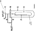
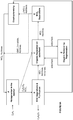
- a system comprising: an electrochemical system comprising an anode chamber comprising an anode in contact with an anode electrolyte comprising metal ions wherein the anode is configured to oxidize the metal ions from a lower oxidation state to a higher oxidation state; and a reactor operably connected to the anode chamber and configured to contact the anode electrolyte comprising the metal ions in the higher oxidation state with an unsaturated and/or saturated hydrocarbon to form one or more organic compounds comprising halogenated or sulfonated hydrocarbon and the metal ion in the lower oxidation state, wherein the reactor has a length:diameter ratio of between 2-40.
- the reactor is configured to produce the halogenated or sulfonated hydrocarbon with more than 0.5 STY or more than 80% selectivity. In some instances of the above noted aspect and instance, the reactor has a length/diameter ratio of between about 20-40. In some instances of the above noted aspect and instances, the reactor is a packed-bed reactor or a trickle-bed reactor. In some instances of the above noted aspect and instances, the reactor has a packing material comprising structured packing material, unstructured packing material, or combination thereof. In some instances of the above noted aspect and instances, the structured packing material comprises thin corrugated metal plates or gauzes.
- the unstructured packing material comprises raschig rings, pall rings, lessing rings, michael bialecki rings, berl saddles, intalox saddles, super intalox saddles, tellerette® rings, or combinations thereof.
- diameter of the structured packing material is the diameter of the reactor.
- size of the unstructured packing material is between about 1 ⁇ 4 of an inch to about 5 inches.
- the unsaturated hydrocarbon is ethylene
- the halogenated hydrocarbon is ethylene dichloride
- the metal ion is copper chloride, or combinations thereof.
- the electrochemical system further comprises a cathode chamber comprising a cathode in contact with a cathode electrolyte wherein the anode chamber and the cathode chamber are separated by an anion exchange membrane comprising a reinforcing material comprising polymer and wherein thickness of the membrane is between 20-130um.
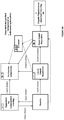
- a system comprising an electrochemical system comprising an anode chamber comprising an anode in contact with an anode electrolyte comprising metal ion wherein the anode is configured to oxidize the metal ion from a lower oxidation state to a higher oxidation state; a reactor operably connected to the anode chamber and configured to react an unsaturated hydrocarbon or saturated hydrocarbon in an aqueous medium with the anode electrolyte comprising the metal ion in the higher oxidation state to form one or more organic compounds comprising halogenated or sulfonated hydrocarbon and the metal ion in the lower oxidation state; and a separator configured to separate and purify the one or more organic compounds comprising halogenated or sulfonated hydrocarbon from the aqueous medium.
- the separator comprises reaction separation reactor system, compression-cooling system, liquid-liquid separation system, vapor-liquid separation system, scrubbing system, purification subprocess system, adsorbent, or combinations thereof.
- the reactor is a reaction separation reactor.
- the reaction separation reactor is a reactive distillation reactor, reactive extraction reactor, or combination thereof.
- the liquid-liquid separation system comprises decanter, extractant, or combination thereof;
- the vapor-liquid separation system comprises flash column, a distillation column, or combination thereof;
- the purification subprocess system comprises decanter, sorbent, distillation column, or combinations thereof; and/or the scrubber comprises column comprising an alkali.
- the separator is configured to produce the halogenated or sulfonated hydrocarbon with more than about 90% yield and/or more than about 90% purity.
- the aqueous medium obtained after the separator comprises the metal ion and less than about 1% or no organic compound.
- the reactor is a trickle-bed reactor.
- the reactor is a packed-bed reactor.
- the reactor has a length/diameter ratio of the reactor is between about 2-30; or between 4-25, or between 6-15; or between 2:1-10:1 or about 3:1 or about 4:1.
- the reactor has a packing material comprising structured or unstructured packing material.
- the structured packing material comprises thin corrugated metal plates or gauzes.
- the unstructured packing material comprises Raschig rings, Pall rings, Lessing rings, Michael Bialecki rings, Berl saddles, Intalox saddles, super intalox saddles, tellerette® rings, or combinations thereof.
- the size of the packing material may be between about 1 ⁇ 4 of an inch to about 5 inches.
- the unsaturated hydrocarbon is ethylene and the halogenated hydrocarbon is EDC.
- the metal ion is copper.
- the electrochemical system is made of corrosion resistant material comprising titanium.
- the electrochemical system comprises bipolar electrolyzers.
- the systems further include one or more heat exchange units.
- the one or more heat exchange units are configured to exchange heat between the anode electrolyte, the unsaturated or saturated hydrocarbon, the aqueous medium comprising the metal ion in the lower and higher oxidation state, steam, water, or combinations thereof.
- the unsaturated hydrocarbon ethylene
- the saturated hydrocarbon such as formula III
- the halogenated hydrocarbon e.g., copper
- the unsaturated hydrocarbon is ethylene
- the organic compound comprises EDC, or combinations thereof.
- the anode and the cathode is separated by anion exchange membrane comprising a reinforced material and a thickness of between 20-130 um or between 20-75 um or between 50-100 um. Such membranes have been described in detail herein.
- the anion exchange membrane separates a third electrolyte from the anode electrolyte.
- the anode and the cathode are further separated by a cation exchange membrane that separates the third electrolyte from the cathode electrolyte.
- the separator further comprises a recirculating system operably connected to the anode to recirculate the aqueous medium comprising metal ion in the lower oxidation state to the anode electrolyte.
- the anode is a diffusion enhancing anode such as, but not limited to, a porous anode.
- the porous anode may be flat or corrugated, as described herein.
- the separator further comprises an adsorbent selected from activated charcoal, alumina, activated silica, polymer, and combinations thereof.
- system further comprises a ligand in the anode electrolyte wherein the ligand is configured to interact with the metal ion.
- the cathode is a gas-diffusion cathode configured to react oxygen gas and water to form hydroxide ions.
- the cathode is a hydrogen gas producing cathode configured to form hydrogen gas and hydroxide ions by reducing water.
- the cathode is a hydrogen gas producing cathode configured to reduce an acid, such as, hydrochloric acid to hydrogen gas.
- the cathode is a gas-diffusion cathode configured to react hydrochloric acid and oxygen to form water.
- the anode is configured to not form a gas.
- system further comprises a precipitator configured to contact the cathode electrolyte with divalent cations to form a carbonate and/or bicarbonate product.
- the metal ion is copper.
- the unsaturated hydrocarbon is ethylene.
- the one or more organic compounds comprise ethylene dichloride and chloroethanol, and may further comprise dichloroacetaldehyde, trichloroacetaldehyde, and combinations thereof.
- a method in accordance with claim 1, comprising: contacting an anode with an anode electrolyte wherein the anode electrolyte comprises metal chloride; oxidizing the metal chloride from a lower oxidation state to a higher oxidation state at the anode; and reacting ethylene with the anode electrolyte comprising the metal chloride in the higher oxidation state in an aqueous medium, to form one or more organic compounds comprising ethylene dichloride and chloroethanol and the metal chloride in the lower oxidation state, wherein the reacting is under one or more of reaction conditions favorable to produce the halogenated hydrocarbons with more than about 0.5 STY.
- the one or more of reaction conditions comprise temperature between 100-200°C, pressure of between 200-300psig, or combination thereof. In some embodiments of the aforementioned aspect and embodiment, the one or more of reaction conditions comprise metal ion concentration, ratio of metal ion in the lower oxidation state to the metal ion in the higher oxidation state in the anode electrolyte, partial pressure of the unsaturated or saturated hydrocarbon, partial pressure of water vapor, flow rate of the anode electrolyte, flow rate of the unsaturated or saturated hydrocarbon, density of the anode electrolyte, viscosity of the anode electrolyte, reaction time, or combinations thereof.
- the metal ion concentration is between about 1-8M, the ratio is between about 1:8-1:5, the flow rate of the anode electrolyte is between about 150-300 kg/h, or combinations thereof.
- the one or more of reaction conditions are favorable to produce the halogenated hydrocarbon with more than about 80% selectivity.
- the unsaturated hydrocarbon is ethylene
- the halogenated hydrocarbon is ethylene dichloride
- the metal ion is copper chloride, or combinations thereof.
- a method in accordance with claim 1, comprising contacting an anode with an anode electrolyte wherein the anode electrolyte comprises metal chloride; oxidizing the metal chloride from a lower oxidation state to a higher oxidation state at the anode; reacting ethylene with the anode electrolyte comprising the metal chloride in the higher oxidation state in an aqueous medium, to form one or more organic compounds comprising ethylene dichloride and chloroethanol and the metal chloride in the lower oxidation state; and separating and purifying the one or more organic compounds from the aqueous medium.
- the separating and purifying comprises reaction separation process, compression-cooling process.
- the method further comprises liquid-liquid separation process, vapor-liquid separation process and a scrubbing process, and may comprise a purification subprocess, adsorption, and combinations thereof.
- the reacting step includes reaction separation.
- the reaction separation comprises reactive distillation, reactive extraction, or combination thereof.
- the liquid-liquid separation process comprises decantation, and in some embodiments of the aforementioned aspect and embodiments, the liquid-liquid separation process further comprises extraction.
- the vapor-liquid separation process may comprise flash distillation, distillation, or combination thereof.
- the purification subprocess process may comprise decantation, adsorption, distillation, or combinations thereof.
- the scrubber comprises treatment with an alkali.
- the separation and purification produces the halogenated hydrocarbon with more than about 90% yield and/or more than about 90% purity. In some embodiments of the aforementioned aspect and embodiments, the separation and purification produces the aqueous medium comprising the metal chloride and less than about 1% or no organic compound.
- the method further comprises one or more of heat exchanges between the anode electrolyte, the ethylene, the aqueous medium comprising the metal chloride in the lower and higher oxidation state, steam, water, or combinations thereof.
- the unsaturated hydrocarbon is ethylene and the halogenated hydrocarbon is EDC.
- the metal ion is copper.
- the reaction produces EDC with about or more than 0.1 STY and more than 95% selectivity.
- the cathode is a hydrogen gas producing cathode that reduces water to hydrogen gas and hydroxide ions. In some embodiments of the aforementioned aspect, the cathode is a hydrogen gas producing cathode that reduces hydrochloric acid to hydrogen gas. In some embodiments of the aforementioned aspect, the cathode is an oxygen depolarizing cathode that reacts with hydrochloric acid and oxygen gas to form water.
- the aqueous medium that is recirculated back to the anode electrolyte comprises less than 10000ppm, or less than 1000ppm or less than 800ppm or less than 500ppm or less than 250ppm or less than 100ppm or less than 50 ppm or less than 10 ppm or less than 1 ppm of the organic compound(s). In some embodiments of the aforementioned aspect and embodiments, the aqueous medium comprises between 5-95wt% water, or between 5-90wt% water, or between 5-99wt% water.
- the metal ion includes, but not limited to, iron, chromium, copper, tin, silver, cobalt, uranium, lead, mercury, vanadium, bismuth, titanium, ruthenium, osmium, europium, zinc, cadmium, gold, nickel, palladium, platinum, rhodium, iridium, manganese, technetium, rhenium, molybdenum, tungsten, niobium, tantalum, zirconium, hafnium, and combination thereof.
- the metal ion includes, but not limited to, iron, chromium, copper, and tin.
- the metal ion is copper. In some embodiments, the lower oxidation state of the metal ion is 1+, 2+, 3+, 4+, or 5+. In some embodiments, the higher oxidation state of the metal ion is 2+, 3+, 4+, 5+, or 6+.
- the metal ion is copper that is converted from Cu + to Cu 2+
- the metal ion is iron that is converted from Fe 2+ to Fe 3+
- the metal ion is tin that is converted from Sn 2+ to Sn 4+
- the metal ion is chromium that is converted from Cr 2+ to Cr 3+
- the metal ion is platinum that is converted from Pt 2+ to Pt 4+ , or combination thereof.
- the method further comprises adding a ligand to the anode electrolyte wherein the ligand interacts with the metal ion.
- the method further comprises reacting ethylene with the anode electrolyte comprising the metal chloride in the higher oxidation state and the ligand, wherein the reaction is in an aqueous medium.
- the reaction of ethylene with the anode electrolyte comprising the metal chloride in the higher oxidation state is halogenation using the metal chloride in the higher oxidation state resulting in halohydrocarbons (comprising ethylene dichloride and chloroethanol), and the metal chloride in the lower oxidation state.
- the metal chloride in the lower oxidation state is re-circulated back to the anode electrolyte.
- the anode electrolyte comprising the metal chloride in the higher oxidation state further comprises the metal chloride in the lower oxidation state.
- the unsaturated hydrocarbon is ethylene and the halogenated hydrocarbon is ethylene dichloride.
- the method further comprises forming vinyl chloride monomer from the ethylene dichloride and forming poly(vinyl chloride) from the vinyl chloride monomer.
- the saturated hydrocarbon is methane, ethane, or propane.
- the one or more organic compounds comprise ethylene dichloride and chloroethanol, and may further comprise dichloroacetaldehyde, trichloroacetaldehyde, or combinations thereof.
- the method further comprises contacting a diffusion enhancing anode such as, but not limited to, a porous anode with the anode electrolyte.
- the diffusion enhancing anode such as, but not limited to, the porous anode has been described herein.
- the present electrochemical system and method can be configured with an alternative, equivalent salt solution, e.g., a potassium chloride solution or sodium chloride solution or a magnesium chloride solution or sodium sulfate solution or ammonium chloride solution, to produce an equivalent alkaline solution, e.g., potassium hydroxide or sodium hydroxide or magnesium hydroxide in the cathode electrolyte.
- an equivalent salt solution e.g., a potassium chloride solution or sodium chloride solution or a magnesium chloride solution or sodium sulfate solution or ammonium chloride solution
- the electrochemical cells described herein provide an efficient and low voltage system where the metal compound such as metal halide, e.g., metal chloride or a metal sulfate with the higher oxidation state produced by the anode can be used for purposes, such as, but not limited to, generation of halohydrocarbons or sulfohydrocarbons from hydrocarbons in high yield and selectivity.
- the metal compound such as metal halide, e.g., metal chloride or a metal sulfate with the higher oxidation state produced by the anode can be used for purposes, such as, but not limited to, generation of halohydrocarbons or sulfohydrocarbons from hydrocarbons in high yield and selectivity.
- methods that include contacting an anode with a metal chloride in an anode electrolyte in an anode chamber; oxidizing the metal chloride from a lower oxidation state to a higher oxidation state at the anode; contacting a cathode with a cathode electrolyte in a cathode chamber; forming an alkali, water, and/or hydrogen gas at the cathode; contacting the anode electrolyte comprising metal chloride in the higher oxidation state with ethylene to form halogenated hydrocarbon (comprising ethylene dichloride and chloroethanol) and form the metal chloride solution comprising metal chloride in the lower oxidation state; and separating and/or purifying the halogenated hydrocarbon (comprising ethylene dichloride and chloroethanol) from the metal chloride solution.
- the separated metal chloride solution comprising metal chloride in the lower oxidation state and optionally comprising metal chloride in the
- Also described are systems that include an anode chamber comprising an anode in contact with a metal ion in an anode electrolyte, wherein the anode is configured to convert the metal ion from a lower oxidation state to a higher oxidation state; and a cathode chamber comprising a cathode in contact with a cathode electrolyte wherein the cathode is configured to form an alkali, water, and/or hydrogen gas in the cathode electrolyte; a reactor operably connected to the anode chamber and configured to contact the anode electrolyte comprising metal ion in the higher oxidation state with an unsaturated and/or saturated hydrocarbon to form halogenated or sulfonated hydrocarbon and form the metal ion solution comprising metal ion in the lower oxidation state; and a separator to separate and/or purify the halogenated or sulfonated hydrocarbon from the metal ions solution.
- system further comprises a recirculation system to recirculate the separated metal ion solution comprising metal ion in the lower oxidation state and optionally comprising metal ion in the higher oxidation state, back to the anode electrolyte.
- FIG. 1A An illustrative example of an electrochemical system producing anode electrolyte with metal ion in the higher oxidation state integrated with a reactor system for generation of halohydrocarbon or sulfohydrocarbon from hydrocarbon and metal ion in the higher oxidation state, and further the reactor system integrated with the separator system to separate the halohydrocarbon or sulfohydrocarbon from the metal ion solution, is as illustrated in Fig. 1A .
- the electrochemical system 100A of Fig. 1A includes an anode and a cathode separated by anion exchange membrane and cation exchange membrane creating a third chamber containing a third electrolyte, NaCl.
- the anode chamber includes the anode and an anode electrolyte in contact with the anode.
- the cathode chamber includes the cathode and a cathode electrolyte in contact with the cathode.
- the metal ion is oxidized in the anode chamber from the lower oxidation state M L+ to the higher oxidation state M H+ which metal in the higher oxidation state is then used for reactions in a reactor, such as reaction with hydrocarbon, such as, unsaturated or saturated hydrocarbon to produce halohydrocarbon or sulfohydrocarbon.
- the metal ion in the higher oxidation state is consequently reduced to metal ion in the lower oxidation state.
- the metal ion solution is separated from the halohydrocarbon or sulfohydrocarbon (organics) in a separator before the metal ion solution is recirculated back to the anode electrolyte of the electrochemical system.
- the metal ion solution going into the anode electrolyte and the metal ion solution coming out of the anode electrolyte may contain a mix of the metal ion in the lower oxidation state and the higher oxidation state except that the metal ion solution coming out of the anode electrolyte has higher amount of metal ion in the higher oxidation state than the metal ion solution going into the anode electrolyte.
- the system 100A of Fig. 1A is for illustration purposes only and metal ions with different oxidations states (e.g., chromium, tin etc.); other electrochemical systems described herein; the third electrolyte other than sodium chloride such as sodium sulfate; and other cathodes producing water and/or hydrogen gas, are variations that are equally applicable to this system.
- the reactor may be a combination of one or more reactors and the separator may be a combination of one or more separators or separation units. The reactors and the separators have been described herein in detail.
- the metal compound produced by the anode chamber may be used as is or may be purified before reacting with unsaturated hydrocarbon or saturated hydrocarbon for the generation of halohydrocarbon or sulfohydrocarbon.
- the metal compound/solution in the higher oxidation state is treated with the ethylene gas to form a halohydrocarbon product, such as ethylene dichloride (EDC).
- EDC ethylene dichloride
- the ethylene dichloride may also be known as 1,2-dichloroethane, dichloroethane, 1,2-ethylene dichloride, glycol dichloride, freon 150, etc.
- the electrochemical system of the invention is integrated with vinyl chloride monomer (VCM) production facility or polyvinylchloride (PVC) production facility such that the EDC formed via the systems and methods of the invention is used in VCM and/or PVC production.
- VCM vinyl chloride monomer
- PVC polyvinylchloride
- the metal ion solutions may be separated and/or purified before and after the reaction in the reactor.
- the products made in the reactor may also be subjected to organic separation and/or purification before their commercial use.
- the separation and/or purification may include one or more of the separation and purification of the organic compounds from the metal ion solution; the separation and purification of the organic compounds from each other; and separation and purification of the metal ion in the lower oxidation state from the metal ion in the higher oxidation state, to improve the overall yield of the organic product, improve selectivity of the organic product, improve purity of the organic product, improve efficiency of the systems, improve ease of use of the solutions in the overall process, improve reuse of the metal solution in the electrochemical and reaction process, and to improve the overall economics of the process.
- the methods and systems including, but not limited to, the metal ions; ligands; the electrochemical cell, anode, cathode, and membranes; the reactor system integrated with the electrochemical system; and the separator system for the separation and optional purification of the organic compounds from the metal ion solution, the separation and optional purification of the organic compounds from side products, and the separation and optional purification of the metal compound in lower oxidation state mixed with metal compound in the higher oxidation state.
- the systems and methods described herein provide an electrochemical cell that produces various products, such as, but not limited to, metal salts formed at the anode, the metal salts used to form various other chemicals, alkali formed at the cathode, alkali used to form various other products, and/or hydrogen gas formed at the cathode. All of such products have been defined herein and may be called green chemicals since such chemicals are formed using the electrochemical cell that runs at low voltage or energy and high efficiency. The low voltage or less energy intensive process described herein would lead to lesser emission of carbon dioxide as compared to conventional methods of making similar chemicals or products.
- the chemicals or products are formed by the capture of carbon dioxide from flue gas in the alkali generated at the cathode, such as, but not limited to, carbonate and bicarbonate products.
- carbonate and bicarbonate products are green chemicals as they reduce the pollution and provide cleaner environment.
- the electrochemical cell provided herein may be any electrochemical cell where the metal ion in the lower oxidation state is converted to the metal ion in the higher oxidation state in the anode chamber.
- cathode reaction may be any reaction that does or does not form an alkali in the cathode chamber.
- Such cathode consumes electrons and carries out any reaction including, but not limited to, the reaction of water to form hydroxide ions and hydrogen gas or reaction of oxygen gas and water to form hydroxide ions or reduction of protons from an acid such as hydrochloric acid to form hydrogen gas or reaction of protons from hydrochloric acid and oxygen gas to form water.
- the electrochemical cells may include production of alkali in the cathode chamber of the cell.
- the alkali generated in the cathode chamber may be used as is for commercial purposes or may be treated with divalent cations to form divalent cation containing carbonates/bicarbonates.
- the alkali generated in the cathode chamber may be used to sequester or capture carbon dioxide.
- the carbon dioxide may be present in flue gas emitted by various industrial plants.
- the carbon dioxide may be sequestered in the form of carbonate and/or bicarbonate products. Therefore, both the anode electrolyte as well as the cathode electrolyte can be used for generating products that may be used for commercial purposes thereby providing a more economical, efficient, and less energy intensive process.
- electrochemical systems and methods described herein provide one or more advantages over conventional electrochemical systems known in the art, including, but not limited to, no requirement of gas diffusion anode; higher cell efficiency; lower voltages; platinum free anode; sequestration of carbon dioxide; green and environment friendly chemicals; and/or formation of various commercially viable products.
- electrochemical cells used in the methods and systems provided herein are as illustrated in the figures and as described herein. It is to be understood that the figures are for illustration purposes only and that variations in the reagents and set up are well within the scope of the invention. All the electrochemical methods and systems described herein do not produce a gas at the anode such as chlorine gas, as is found in the chlor-alkali systems. All the systems and methods that relate to the halogenation or sulfonation of the unsaturated or saturated hydrocarbon, do not use oxygen gas in the catalytic reactor.
- a gas at the anode such as chlorine gas
- All the systems and methods that relate to the halogenation or sulfonation of the unsaturated or saturated hydrocarbon do not use oxygen gas in the catalytic reactor.
- the electrochemical system 100B includes an anode chamber with an anode in contact with an anode electrolyte where the anode electrolyte contains metal ions in the lower oxidation state (represented as M L+ ) which are converted by the anode to metal ions in the higher oxidation state (represented as M H+ ).
- the metal ion may be in the form of a sulfate, chloride, bromide, or iodide.
- lower oxidation state represented as L+ in M L+ includes the lower oxidation state of the metal.
- lower oxidation state of the metal ion may be 1+, 2+, 3+, 4+, or 5+.
- higher oxidation state represented as H+ in M H+ includes the higher oxidation state of the metal.
- higher oxidation state of the metal ion may be 2+, 3+, 4+, 5+, or 6+.
- the electron(s) generated at the anode are used to drive the reaction at the cathode.
- the cathode reaction may be any reaction known in the art.
- the anode chamber and the cathode chamber may be separated by an ion exchange membrane (IEM) that may allow the passage of ions, such as, but not limited to, sodium ions in some embodiments to the cathode electrolyte if the anode electrolyte is sodium chloride, sodium bromide, sodium iodide, sodium sulfate, or ammonium ions if the anode electrolyte is ammonium chloride etc. or an equivalent solution containing metal halide.
- IEM ion exchange membrane
- Some reactions that may occur at the cathode include, but not limited to, reaction of water to form hydroxide ions and hydrogen gas; reaction of oxygen gas and water to form hydroxide ions; reduction of HCl to form hydrogen gas; or reaction of HCl and oxygen gas to form water.
- the electrochemical system includes a cathode chamber with a cathode in contact with the cathode electrolyte that forms hydroxide ions in the cathode electrolyte.
- the ion exchange membrane allows the passage of anions, such as, but not limited to, chloride ions, bromide ions, iodide ions, or sulfate ions to the anode electrolyte if the cathode electrolyte is e.g., sodium chloride, sodium bromide, sodium iodide, or sodium sulfate or an equivalent solution.
- the sodium ions combine with hydroxide ions in the cathode electrolyte to form sodium hydroxide.
- the anions combine with metal ions to form metal halide or metal sulfate. It is to be understood that other cathodes such as, cathode reducing HCl to form hydrogen gas or cathode reacting both HCl and oxygen gas to form water, are equally applicable to the systems. Such cathodes have been described herein.
- the electrochemical systems of the invention include one or more ion exchange membranes.
- the ion exchange membrane is a cation exchange membrane (CEM), an anion exchange membrane (AEM); or combination thereof.
- the electrochemical system 200 includes a cathode in contact with a cathode electrolyte and an anode in contact with an anode electrolyte.
- the cathode forms hydroxide ions in the cathode electrolyte and the anode converts metal ions from lower oxidation state (M L+ ) to higher oxidation state (M H+ ).
- the anode and the cathode are separated by an anion exchange membrane (AEM) and a cation exchange membrane (CEM).
- AEM anion exchange membrane
- CEM cation exchange membrane
- a third electrolyte (e.g., sodium chloride, sodium bromide, sodium iodide, sodium sulfate, ammonium chloride, or combinations thereof or an equivalent solution) is disposed between the AEM and the CEM.
- the sodium ions from the third electrolyte pass through CEM to form sodium hydroxide in the cathode chamber and the halide anions such as, chloride, bromide or iodide ions, or sulfate anions, from the third electrolyte pass through the AEM to form a solution for metal halide or metal sulfate in the anode chamber.
- the metal halide or metal sulfate formed in the anode electrolyte is then delivered to a reactor for reaction with an unsaturated or saturated hydrocarbon to generate halohydrocarbons or sulfohydrocarbons, respectively.
- the third electrolyte after the transfer of the ions, can be withdrawn from the middle chamber as depleted ion solution.
- the third electrolyte is sodium chloride solution
- the depleted sodium chloride solution may be withdrawn from the middle chamber.
- the depleted salt solution may be used for commercial purposes or may be transferred to the anode and/or cathode chamber as an electrolyte or concentrated for re-use as the third electrolyte. In some instances, the depleted salt solution may be useful for preparing desalinated water. It is to be understood that the hydroxide forming cathode, as illustrated in Fig. 2 is for illustration purposes only and other cathodes such as, cathode reducing HCl to form hydrogen gas or cathode reacting both HCl and oxygen gas to form water, are equally applicable to the systems and have been described further herein.
- the ion exchange membrane described herein is an anion exchange membrane, as illustrated in Fig. 3A .
- the cathode electrolyte (or the third electrolyte in the third chamber) may be a sodium halide, sodium sulfate or an equivalent solution and the AEM is such that it allows the passage of anions to the anode electrolyte but prevents the passage of metal ions from the anode electrolyte to the cathode electrolyte (or to the third electrolyte in the third chamber).
- the ion exchange membrane described herein is a cation exchange membrane, as illustrated in Fig. 3B .
- the anode electrolyte (or the third electrolyte in the third chamber) may be a sodium halide, sodium sulfate or an equivalent solution containing the metal halide solution or an equivalent solution and the CEM is such that it allows the passage of sodium cations to the cathode electrolyte but prevents the passage of metal ions from the anode electrolyte to the cathode electrolyte.
- both the AEM and CEM may be joined together in the electrochemical system.
- the use of one ion exchange membrane instead of two ion exchange membranes may reduce the resistance offered by multiple IEMs and may facilitate lower voltages for running the electrochemical reaction.
- the electrochemical cells in the methods and systems provided herein are membrane electrolyzers.
- the electrochemical cell may be a single cell or may be a stack of cells connected in series or in parallel.
- the electrochemical cell may be a stack of 5 or 6 or 50 or 100 or more electrolyzers connected in series or in parallel.
- Each cell comprises an anode, a cathode, and an ion exchange membrane, as illustrated in Fig. 1A , 1B or Fig. 2 .
- the electrolyzers provided herein are monopolar electrolyzers.
- the electrodes may be connected in parallel as illustrated in Fig. 4A where all anodes and all cathodes are connected in parallel. In such monopolar electrolyzers, the operation takes place at high amperage and low voltage.
- the electrolyzers provided herein are bipolar electrolyzers. In the bipolar electrolyzers, the electrodes may be connected in series as illustrated in Fig. 4B where all anodes and all cathodes are connected in series. In such bipolar electrolyzers, the operation takes place at low amperage and high voltage.
- the electrolyzers are a combination of monopolar and bipolar electrolyzers and may be called hybrid electrolyzers (not shown in the figures). It is to be understood that Figs. 4A and 4B show a stack of three cells for illustration purposes only and the stack may be a combination of two or more electrolyzers.
- the cells are stacked serially constituting the overall electrolyzer and are electrically connected in two ways.
- a single plate called bipolar plate, may serve as base plate for both the cathode and anode.
- the electrolyte solution may be hydraulically connected through common manifolds and collectors internal to the cell stack.
- the stack may be compressed externally to seal all frames and plates against each other which is typically referred to as a filter press design.
- the bipolar electrolyzer may also be designed as a series of cells, individually sealed, and electrically connected through back-to-back contact, typically known as a single element design.
- the single element design may also be connected in parallel in which case it would be a monopolar electrolyzer.
- the cell size may be denoted by the active area dimensions.
- the active area of the electrolyzers used herein may range from 0.5-1.5 meters tall and 0.4-3 meters wide.
- the individual compartment thicknesses may range from 0.5mm-50mm.
- the electrolyzers used in the methods and systems provided herein are made from corrosion resistant materials. Variety of materials were tested (as described in Example 4) in metal solutions such as copper and at varying temperatures, for corrosion testing.
- the materials include, but not limited to, polyvinylidene fluoride, viton, polyether ether ketone, fluorinated ethylene propylene, fiber-reinforced plastic, halar, ultem (PEI), perfluoroalkoxy, tefzel, tyvar, fibre-reinforced plastic-coated with derakane 441-400 resin, graphite, akot, tantalum, hastelloy C2000, titanium Gr.7, titanium Gr.2, or combinations thereof.
- these materials can be used for making the electrochemical cells and/or it components including, but not limited to, tank materials, piping, heat exchangers, pumps, reactors, cell housings, cell frames, electrodes, instrumentation, valves, and all other balance of plant materials.
- the material used for making the electrochemical cell and its components include, but not limited to, titanium Gr.2.
- metal ion or “metal” as used herein, includes any metal ion capable of being converted from lower oxidation state to higher oxidation state.
- metal ions include, but not limited to, iron, chromium, copper, tin, silver, cobalt, uranium, lead, mercury, vanadium, bismuth, titanium, ruthenium, osmium, europium, zinc, cadmium, gold, nickel, palladium, platinum, rhodium, iridium, manganese, technetium, rhenium, molybdenum, tungsten, niobium, tantalum, zirconium, hafnium, and combination thereof.
- the metal ions include, but not limited to, iron, copper, tin, chromium, or combination thereof.
- the metal ion is copper.
- the metal ion is tin.
- the metal ion is iron.
- the metal ion is chromium.
- the metal ion is platinum.
- the "oxidation state" as used herein includes degree of oxidation of an atom in a substance.
- the oxidation state is the net charge on the ion.
- the metal ion may be present as a compound of the metal or an alloy of the metal or combination thereof.
- the anion attached to the metal is same as the anion of the electrolyte.
- Sodium chloride is used as an electrolyte, and a metal chloride, such as, but not limited to, iron chloride, copper chloride, tin chloride, chromium chloride etc. is used as the metal compound.
- the anode electrolyte may be a combination of ions similar to the metal anion and anions different from the metal ion.
- the anode electrolyte may be a mix of sulfate ions as well as chloride ions when the metal anion is chloride.
- the metal ions used in the electrochemical systems described herein may be chosen based on the solubility of the metal in the anode electrolyte and/or cell voltages desired for the metal oxidation from the lower oxidation state to the higher oxidation state.
- the voltage required to oxidize Cr 2+ to Cr 3+ may be lower than that required for Sn 2+ to Sn 4+ , however, the amount of halo hydrocarbon (comprising ethylene dichloride and chloroethanol) formed by the reaction of ethylene with the Cr 3+ may be lower than the halohydrocarbon (ethylene dichloride and chloroethanol) formed with Sn 4+ owing to two chlorine atoms obtained per tin molecule.
- the metal ion oxidation that results in lower cell voltage may be used, such as, but not limited to Cr 2+ .
- a lower voltage may be desired.
- the metal ion that results in higher amount of the product albeit relatively higher voltages may be used, such as, but not limited to Sn 2+ .
- the voltage of the cell may be higher for tin system as compared to the chromium system, however, the concentration of the halohydrocarbon formed with Sn 4+ may offset the higher voltage of the system.
- the products formed by the systems and methods described herein, such as the halohydrocarbons, sulfohydrocarbons, carbonate, bicarbonates, etc. are still green chemicals as they are made by less energy intensive processes as compared to energy input required for conventionally known methods of making the same products.
- the metal ion in the lower oxidation state and the metal ion in the higher oxidation state are both present in the anode electrolyte. In some embodiments, it may be desirable to have the metal ion in both the lower oxidation state and the higher oxidation state in the anode electrolyte. Suitable ratios of the metal ion in the lower and higher oxidation state in the anode electrolyte have been described herein.
- the mixed metal ion in the lower oxidation state with the metal ion in the higher oxidation state may assist in lower voltages in the electrochemical systems and high yield and selectivity in corresponding catalytic reactions with hydrocarbons.
- the metal ion in the anode electrolyte is a mixed metal ion.
- the anode electrolyte containing the copper ion in the lower oxidation state and the copper ion in the higher oxidation state may also contain another metal ion such as, but not limited to, iron.
- the presence of a second metal ion in the anode electrolyte may be beneficial in lowering the total energy of the electrochemical reaction in combination with the catalytic reaction.
- metal compounds that may be used in the systems and methods of the invention include, but are not limited to, copper (I) chloride, iron (II) chloride, tin (II) chloride, chromium (II) chloride, zinc (II) chloride, etc.
- an additive such as a ligand is used in conjunction with the metal ion to improve the efficiency of the metal ion oxidation inside the anode chamber and/or improve the catalytic reactions of the metal ion inside/outside the anode chamber such as, but not limited to reactions with unsaturated hydrocarbon and/or with saturated hydrocarbon.
- the ligand is added along with the metal in the anode electrolyte.
- the ligand is attached to the metal ion.
- the ligand is attached to the metal ion by covalent, ionic and/or coordinate bonds.
- the ligand is attached to the metal ion through vanderwaal attractions.
- the ligand results in one or more of the following: enhanced reactivity of the metal chloride towards etyhylene, enhanced selectivity of the metal chloride towards halogenations of ethylene, enhanced transfer of the halogen from the metal chloride to ethylene, reduced redox potential of the electrochemical cell, enhanced solubility of the metal chloride in the aqueous medium, reduced membrane cross-over of the metal chloride to the cathode electrolyte in the electrochemical cell, reduced corrosion of the electrochemical cell and/or the reactor, enhanced separation of the metal chloride from the organic solution after reaction with ethylene, enhanced separation of the metal chloride from the halogenated hydrocarbon solution (such as adsorbents), and combination thereof.
- the attachment of the ligand to the metal ion increases the size of the metal ion sufficiently higher to prevent its migration through the ion exchange membranes in the cell.
- the anion exchange membrane in the electrochemical cell is such that the migration of the metal ion attached to the ligand from the anode electrolyte to the cathode electrolyte, is prevented. Such membranes are described herein below.
- the anion exchange membrane in the electrochemical cell may be used in conjunction with the size exclusion membrane such that the migration of the metal ion attached to the ligand from the anode electrolyte to the cathode electrolyte, is prevented.
- the attachment of the ligand to the metal ion increases the solubility of the metal ion in the aqueous medium. In some embodiments, the attachment of the ligand to the metal ion reduces the corrosion of the metals in the electrochemical cell as well as the reactor. In some embodiments, the attachment of the ligand to the metal ion increases the size of the metal ion sufficiently higher to facilitate separation of the metal ion from the halogenated hydrocarbon after the reaction. In some embodiments, the presence and/or attachment of the ligand to the metal ion may prevent formation of various halogenated species of the metal ion in the solution and favor formation of only the desired species.
- the presence of the ligand in the copper ion solution may limit the formation of the various halogenated species of the copper ion, such as, but not limited to, [CuCl 3 ] 2- or CuCl 2 0 but favor formation of Cu 2+ /Cu + ion.
- the presence and/or attachment of the ligand in the metal ion solution reduces the overall voltage of the cell by providing one or more of the advantages described above.
- ligand as used herein includes any ligand capable of enhancing the properties of the metal ion.
- ligands include, but not limited to, substituted or unsubstituted aliphatic phosphine, substituted or unsubstituted aromatic phosphine, substituted or unsubstituted amino phosphine, substituted or unsubstituted crown ether, substituted or unsubstituted aliphatic nitrogen, substituted or unsubstituted cyclic nitrogen, substituted or unsubstituted aliphatic sulfur, substituted or unsubstituted cyclic sulfur, substituted or unsubstituted heterocyclic, and substituted or unsubstituted heteroaromatic.
- the concentration of the ligand in the electrochemical cell is dependent on the concentration of the metal ion in the lower and/or the higher oxidation state. In some embodiments, the concentration of the ligand is between 0.25M-5M; or between 0.25M-4M; or between 0.25M-3M; or between 0.5M-5M; or between 0.5M-4M; or between 0.5M-3M; or between 0.5M-2.5M; or between 0.5M-2M; or between 0.5M-1.5M; or between 0.5M-1M; or between 1M-2M; or between 1.5M-2.5M; or between 1.5M-2M.
- the ratio of the concentration of the ligand and the concentration of the Cu(I) ion is between 1:1 to 4:1; or between 1:1 to 3:1; or between 1:1 to 2:1; or is 1:1; or 2:1, or 3:1, or 4:1.
- the solution used in the catalytic reaction i.e., the reaction of the metal chloride in the higher oxidation state with ethylene
- the solution used in the electrochemical reaction contain the concentration of the metal ion in the higher oxidation state, such as Cu(II), between 4.5M-7M, the concentration of the metal ion in the lower oxidation state, such as Cu(I), between 0.25M-1.5M, and the concentration of the ligand between 0.25M-6M.
- the concentration of the sodium chloride in the solution may affect the solubility of the ligand and/or the metal chloride; the yield and selectivity of the catalytic reaction; and/or the efficiency of the electrochemical cell.
- the concentration of sodium chloride in the solution is between 1M-3M.
- the solution used in the catalytic reaction i.e., the reaction of the metal chloride in the higher oxidation state with ethylene, and the solution used in the electrochemical reaction, contain the concentration of the metal ion in the higher oxidation state, such as Cu(II), between 4.5M-7M, the concentration of the metal ion in the lower oxidation state, such as Cu(I), between 0.25M-1.5M, the concentration of the ligand between 0.25M-6M, and the concentration of sodium chloride between 1M-3M.
- the anode may contain a corrosion stable, electrically conductive base support.
- a corrosion stable, electrically conductive base support such as, but not limited to, amorphous carbon, such as carbon black, fluorinated carbons like the specifically fluorinated carbons described in U.S. Pat. No. 4,908,198 and available under the trademark SFCTM carbons.
- electrically conductive base materials include, but not limited to, sub-stoichiometric titanium oxides, such as, Magneli phase sub-stoichiometric titanium oxides having the formula TiO x wherein x ranges from about 1.67 to about 1.9.
- titanium sub-oxides include, without limitation, titanium oxide Ti 4 O7.
- the electrically conductive base materials also include, without limitation, metal titanates such as M x Ti y O z such as M x Ti 4 O 7 , etc.
- metal titanates such as M x Ti y O z such as M x Ti 4 O 7 , etc.
- carbon based materials provide a mechanical support or as blending materials to enhance electrical conductivity but may not be used as catalyst support to prevent corrosion.
- the anode is not coated with an electrocatalyst.
- the gas-diffusion electrodes or general electrodes described herein contain an electrocatalyst for aiding in electrochemical dissociation, e.g. reduction of oxygen at the cathode or the oxidation of the metal chloride at the anode.
- electrocatalysts include, but not limited to, highly dispersed metals or alloys of the platinum group metals, such as platinum, palladium, ruthenium, rhodium, iridium, or their combinations such as platinum-rhodium, platinum-ruthenium, titanium mesh coated with PtIr mixed metal oxide or titanium coated with galvanized platinum; electrocatalytic metal oxides, such as, but not limited to, IrO 2 ; gold, tantalum, carbon, graphite, organometallic macrocyclic compounds, and other electrocatalysts well known in the art for electrochemical reduction of oxygen or oxidation of metal.
- platinum group metals such as platinum, palladium, ruthenium, rhodium, iridium, or their combinations such as platinum-rhodium, platinum-ruthenium, titanium mesh coated with PtIr mixed metal oxide or titanium coated with galvanized platinum
- electrocatalytic metal oxides such as, but not limited to, IrO 2
- the electrodes described herein relate to porous homogeneous composite structures as well as heterogeneous, layered type composite structures wherein each layer may have a distinct physical and compositional make-up, e.g. porosity and electroconductive base to prevent flooding, and loss of the three phase interface, and resulting electrode performance.
- the electrodes provided herein may include anodes and cathodes having porous polymeric layers on or adjacent to the anolyte or catholyte solution side of the electrode which may assist in decreasing penetration and electrode fouling.
- Stable polymeric resins or films may be included in a composite electrode layer adjacent to the anolyte comprising resins formed from non-ionic polymers, such as polystyrene, polyvinyl chloride, polysulfone, etc., or ionic-type charged polymers like those formed from polystyrenesulfonic acid, sulfonated copolymers of styrene and vinylbenzene, carboxylated polymer derivatives, sulfonated or carboxylated polymers having partially or totally fluorinated hydrocarbon chains and aminated polymers like polyvinylpyridine.
- the gas-diffusion cathodes includes such cathodes known in the art that are coated with high surface area coatings of precious metals such as gold and/or silver, precious metal alloys, nickel, and the like.
- the methods and systems provided herein include anode that allows increased diffusion of the electrolyte in and around the anode. Applicants found that the shape and/or geometry of the anode may have an effect on the flow or the velocity of the anode electrolyte around the anode in the anode chamber which in turn may improve the mass transfer and reduce the voltage of the cell.
- the methods and systems provided herein include anode that is a "diffusion enhancing" anode.
- the "diffusion enhancing" anode as used herein includes anode that enhances the diffusion of the electrolyte in and/or around the anode thereby enhancing the reaction at the anode.
- the diffusion enhancing anode is a porous anode.
- the "porous anode” as used herein includes an anode that has pores in it.
- the diffusion enhancing anode such as, but not limited to, the porous anode used in the methods and systems provided herein, may have several advantages over the non-diffusing or non-porous anode in the electrochemical systems including, but not limited to, higher surface area; increase in active sites; decrease in voltage; decrease or elimination of resistance by the anode electrolyte; increase in current density; increase in turbulence in the anode electrolyte; and/or improved mass transfer.
- the diffusion enhancing anode such as, but not limited to, the porous anode may be flat, unflat, or combinations thereof.
- the diffusion enhancing anode such as, but not limited to, the porous anode is in a flat form including, but not limited to, an expanded flattened form, a perforated plate, a reticulated structure, etc.
- the diffusion enhancing anode such as, but not limited to, the porous anode includes an expanded mesh or is a flat expanded mesh anode.
- the diffusion enhancing anode such as, but not limited to, the porous anode is unflat or has a corrugated geometry.
- the corrugated geometry of the anode may provide an additional advantage of the turbulence to the anode electrolyte and improve the mass transfer at the anode.
- the "corrugation" or “corrugated geometry” or “corrugated anode” as used herein includes an anode that is not flat or is unflat.
- the corrugated geometry of the anode includes, but not limited to, unflattened, expanded unflattened, staircase, undulations, wave like, 3-D, crimp, groove, pleat, pucker, ridge, ruche, ruffle, wrinkle, woven mesh, punched tab style, etc.
- FIG. 5 Few examples of the flat and the corrugated geometry of the diffusion enhancing anode such as, but not limited to, the porous anode are as illustrated in Fig. 5 . These examples are for illustration purposes only and any other variation from these geometries is well within the scope of the invention.
- the figure A in Fig. 5 is an example of a flat expanded anode and the figure B in Fig. 5 is an example of the corrugated anode.
- the use of the diffusion enhancing anode such as, but not limited to, the porous anode results in the voltage savings of between 10-500mV, or between 50-250mV, or between 100-200mV, or between 200-400mV, or between 25-450mV, or between 250-350mV, or between 100-500mV, as compared to the non-diffusing or the non-porous anode.
- the use of the corrugated anode results in the voltage savings of between 10-500mV, or between 50-250mV, or between 100-200mV, or between 200-400mV, or between 25-450mV, or between 250-350mV, or between 100-500mV, as compared to the flat porous anode.
- the diffusion enhancing anode such as, but not limited to, the porous anode may be characterized by various parameters including, but not limited to, mesh number which is a number of lines of mesh per inch; pore size; thickness of the wire or wire diameter; percentage open area; amplitude of the corrugation; repetition period of the corrugation, etc.
- These characteristics of the diffusion enhancing anode such as, but not limited to, the porous anode may affect the properties of the porous anode, such as, but not limited to, increase in the surface area for the anode reaction; reduction of solution resistance; reduction of voltage applied across the anode and the cathode; enhancement of the electrolyte turbulence across the anode; and/or improved mass transfer at the anode.
- the diffusion enhancing anode such as, but not limited to, the porous anode may have a pore opening size (as illustrated in Fig. 5 ) ranging between 2xlmm to 20x10mm; or between 2x1mm to 10x5mm; or between 2xlmm to 5x5mm; or between 1x1mm to 20x10mm; or between 1x1mm to 10x5mm; or between 1x1mm to 5x5mm; or between 5xlmm to 10x5mm; or between 5xlmm to 20x10mm; between 10x5mm to 20x10mm and the like.
- a pore opening size as illustrated in Fig. 5
- the pore size of the porous anode may also be dependent on the geometry of the pore.
- the geometry of the pore may be diamond shaped or square shaped.
- the pore size may be, e.g., 3x10mm with 3 mm being widthwise and 10mm being lengthwise of the diamond, or vice versa.
- the pore size would be, e.g., 3mm each side.
- the woven mesh may be the mesh with square shaped pores and the expanded mesh may be the mesh with diamond shaped pores.
- the diffusion enhancing anode such as, but not limited to, the porous anode may have a pore wire thickness or mesh thickness (as illustrated in Fig. 5 ) ranging between 0.5mm to 5mm; or between 0.5mm to 4mm; or between 0.5mm to 3mm; or between 0.5mm to 2mm; or between 0.5mm to 1mm; or between 1mm to 5mm; or between 1mm to 4mm; or between 1mm to 3mm; or between 1mm to 2mm; or between 2mm to 5mm; or between 2mm to 4mm; or between 2mm to 3mm; or between 0.5mm to 2.5mm; or between 0.5mm to 1.5mm; or between 1mm to 1.5mm; or between 1mm to 2.5mm; or between 2.5mm to 3mm; or 0.5mm; or 1mm; or 2mm; or 3mm.
- a pore wire thickness or mesh thickness as illustrated in Fig. 5 ) ranging between 0.5mm to 5mm; or between 0.5mm to 4mm; or between 0.5mm to 3mm; or between
- the diffusion enhancing anode such as, but not limited to, the porous anode is the corrugated anode
- the corrugated anode may have a corrugation amplitude (as illustrated in Fig.
- the corrugated anode when the diffusion enhancing anode such as, but not limited to, the porous anode is the corrugated anode, then the corrugated anode may have a corrugation period (not illustrated in figures) ranging between 2mm to 35mm; or between 2mm to 32mm; or between 2mm to 30mm; or between 2mm to 25mm; or between 2mm to 20mm; or between 2mm to 16mm; or between 2mm to 10mm; or between 5mm to 35mm; or between 5mm to 30mm; or between 5mm to 25mm; or between 5mm to 20mm; or between 5mm to 16mm; or between 5mm to 10mm; or between 15mm to 35mm; or between 15mm to 30mm; or between 15mm to 25mm; or between 15mm to 20mm; or between 20mm to 35mm; or between 25mm to 30mm; or between 25mm to 35mm; or between 25mm to 30mm.
- a corrugation period (not illustrated in figures) ranging between 2mm to 35mm; or between
- the diffusion enhancing anode such as, but not limited to, the porous anode is made of an electro conductive base metal such as titanium coated with or without electrocatalysts.
- electro conductive base metal such as titanium coated with or without electrocatalysts.
- electrically conductive base materials include, but not limited to, sub-stoichiometric titanium oxides, such as, Magneli phase sub-stoichiometric titanium oxides having the formula TiO x wherein x ranges from about 1.67 to about 1.9.
- titanium sub-oxides include, without limitation, titanium oxide Ti 4 O 7 .
- the electrically conductive base materials also include, without limitation, metal titanates such as M x Ti y O z such as M x Ti 4 O 7 , etc.
- electrocatalysts include, but not limited to, highly dispersed metals or alloys of the platinum group metals, such as platinum, palladium, ruthenium, rhodium, iridium, or their combinations such as platinum-rhodium, platinum-ruthenium, titanium mesh coated with PtIr mixed metal oxide or titanium coated with galvanized platinum; electrocatalytic metal oxides, such as, but not limited to, IrO 2 ; gold, tantalum, carbon, graphite, organometallic macrocyclic compounds, and other electrocatalysts well known in the art.
- the diffusion enhancing anode such as, but not limited to, the porous anode may be commercially available or may be fabricated with appropriate metals.
- the electrodes may be coated with electrocatalysts using processes well known in the art.
- the metal may be dipped in the catalytic solution for coating and may be subjected to processes such as heating, sand blasting etc.
- Such methods of fabricating the anodes and coating with catalysts are well known in the art.
- a turbulence promoter is used in the anode compartment to improve mass transfer at the anode. For example, as the current density increases in the electrochemical cell, the mass transfer controlled reaction rate at the anode is achieved. The laminar flow of the anolyte may cause resistance and diffusion issues.
- a turbulence promoter may be used in the anode compartment.
- a "turbulence promoter" as used herein includes a component in the anode compartment of the electrochemical cell that provides turbulence. In some embodiments, the turbulence promoter may be provided at the back of the anode, i.e.
- the turbulence promoter may be provided between the anode and the anion exchange membrane.
- the electrochemical systems shown in Fig. 1A , 1B , 2 , 4A or 4B may have a turbulence promoter between the anode and the ion exchange membrane such as the anion exchange membrane and/or have the turbulence promoter between the anode and the outer wall of the cell.
- the turbulence promoter is bubbling of the gas in the anode compartment.
- the gas can be any inert gas that does not react with the constituents of the anolyte.
- the gas includes, but not limited to, air, nitrogen, argon, and the like.
- the bubbling of the gas at the anode can stir up the anode electrolyte and improve the mass transfer at the anode. The improved mass transfer can result in the reduced voltage of the cell.
- turbulence promoter examples include, but not limited to, incorporating a carbon cloth next to the anode, incorporating a carbon/graphite felt next to the anode, an expanded plastic next to the anode, a fishing net next to the anode, a combination of the foregoing, and the like.
- cathodes can be used in combination with any of the anodes described above.
- the cathode used in the electrochemical systems of the present disclosure is a hydrogen gas producing cathode.
- the hydrogen gas formed at the cathode may be vented out or captured and stored for commercial purposes.
- the M H+ formed at the anode combines with halide ions, e.g. chloride ions to form metal chloride in the higher oxidation state such as, but not limited to, FeCl 3 , CrCl 3 , SnCl 4 , or CuCl 2 etc.
- the hydroxide ion formed at the cathode combines with sodium ions to form sodium hydroxide.
- the cathode used in the electrochemical systems of the present disclosure is a hydrogen gas producing cathode that does not form an alkali. Following are the reactions that take place at the cathode and the anode:
- the hydrogen gas may be vented out or captured and stored for commercial purposes.
- the M H+ formed at the anode combines with halide ions, e.g. chloride ions to form metal chloride in the higher oxidation state such as, but not limited to, FeCl 3 , CrCl 3 , SnCl 4 , or CuCl 2 etc.
- the cathode in the electrochemical systems of the present disclosure may be a gas-diffusion cathode.
- the cathode in the electrochemical systems of the present disclosure may be a gas-diffusion cathode forming an alkali at the cathode.
- the "gas-diffusion cathode,” or “gas-diffusion electrode,” or other equivalents thereof include any electrode capable of reacting a gas to form ionic species.
- the gas-diffusion cathode, as used herein is an oxygen depolarized cathode (ODC).
- ODC oxygen depolarized cathode
- Such gas-diffusion cathode may be called gas-diffusion electrode, oxygen consuming cathode, oxygen reducing cathode, oxygen breathing cathode, oxygen depolarized cathode, and the like.
- the M H+ formed at the anode combines with halide ions, e.g. chloride ions to form metal chloride MCl n such as, but not limited to, FeCl 3 , CrCl 3 , SnCl 4 , or CuCl 2 etc.
- halide ions e.g. chloride ions to form metal chloride MCl n such as, but not limited to, FeCl 3 , CrCl 3 , SnCl 4 , or CuCl 2 etc.
- the hydroxide ion formed at the cathode reacts with sodium ions to form sodium hydroxide.
- the oxygen at the cathode may be atmospheric air or any commercial available source of oxygen.
- the methods and systems containing the gas-diffusion cathode or the ODC, as described herein may result in voltage savings as compared to methods and systems that include the hydrogen gas producing cathode.
- the voltage savings in-turn may result in less electricity consumption and less carbon dioxide emission for electricity generation. This may result in the generation of greener chemicals such as sodium hydroxide, halogentated hydrocarbons and/or acids, that are formed by the efficient and energy saving methods and systems of the invention.
- both the systems i.e. systems containing the ODC and the systems containing hydrogen gas producing cathode of the invention show significant voltage savings as compared to chlor-alkali system conventionally known in the art.
- the voltage savings in-turn may result in less electricity consumption and less carbon dioxide emission for electricity generation. This may result in the generation of greener chemicals such as sodium hydroxide and/or halogentated hydrocarbons, that are formed by the efficient and energy saving methods and systems of the invention.
- the voltage savings is beneficial in production of the halogenated hydrocarbons, such as EDC, which is typically formed by reacting ethylene with chlorine gas generated by the high voltage consuming chlor-alkali process.
- the electrochemical system of the present disclosure (2 or 3-compartment cells with hydrogen gas producing cathode or ODC) has a theoretical voltage savings of more than 0.5V, or more than 1V, or more than 1.5V, or between 0.5-3V, as compared to chlor-alkali process.
- this voltage saving is achieved with a cathode electrolyte pH of between 7-15, or between 7-14, or between 6-12, or between 7-12, or between 7-10.
- Theoretical E total for the chlor-alkali process then is 2.19V.
- Theoretical E total for the hydrogen gas producing cathode in the system of the invention is between 0.989 to 1.53V and E total for ODC in the system of the present disclosure then is between -0.241 to 0.3V, depending on the concentration of copper ions in the anode electrolyte.
- the electrochemical systems of the present disclosure bring the theoretical voltage savings in the cathode chamber or the theoretical voltage savings in the cell of greater than 3V or greater than 2V or between 0.5-2.5V or between 0.5-2.0V or between 0.5-1.5V or between 0.5-1.0V or between 1-1.5V or between 1-2V or between 1-2.5V or between 1.5-2.5V, as compared to the chlor-alkali system.
- the cathode in the electrochemical systems of the present disclosure may be a gas-diffusion cathode that reacts HCl and oxygen gas to form water.
- the M H+ formed at the anode combines with chloride ions to form metal chloride MCl n such as, but not limited to, FeCl 3 , CrCl 3 , SnCl 4 , or CuCl 2 etc.
- the oxygen at the cathode may be atmospheric air or any commercial available source of oxygen.
- the cathode electrolyte containing the alkali maybe withdrawn from the cathode chamber.
- the alkali produced in the methods and systems provided herein is used as is commercially or is used in commercial processes known in the art.
- the purity of the alkali formed in the methods and systems may vary depending on the end use requirements. For example, methods and systems provided herein that use an electrochemical cell equipped with membranes may form a membrane quality alkali which may be substantially free of impurities. In some embodiments, a less pure alkali may also be formed by avoiding the use of membranes or by adding the carbon to the cathode electrolyte.
- the alkali may be separated from the cathode electrolyte using techniques known in the art, including but not limited to, diffusion dialysis. In some embodiments, the alkali formed in the cathode electrolyte is more than 2% w/w or more than 5% w/w or between 5-50% w/w.
- the systems include a collector configured to collect the alkali from the cathode chamber and connect it to the appropriate process which may be any means to collect and process the alkali including, but not limited to, tanks, collectors, pipes etc. that can collect, process, and/or transfer the alkali produced in the cathode chamber for use in the various commercial processes.
- a collector configured to collect the alkali from the cathode chamber and connect it to the appropriate process which may be any means to collect and process the alkali including, but not limited to, tanks, collectors, pipes etc. that can collect, process, and/or transfer the alkali produced in the cathode chamber for use in the various commercial processes.
- the alkali formed in the cathode electrolyte is used in making products such as, but not limited to carbonates and/or bicarbonates by contacting the carbon dioxide with the alkali.
- products such as, but not limited to carbonates and/or bicarbonates by contacting the carbon dioxide with the alkali.
- Such contact of the carbon dioxide, the sources of the carbon dioxide, and the formation of carbonate and/or bicarbonate products, is fully described in US Patent No. 9,200,375, filed March 13, 2013 .
- the cathode electrolyte and the anode electrolyte are separated in part or in full by an ion exchange membrane.
- the ion exchange membrane is an anion exchange membrane or a cation exchange membrane.
- the cation exchange membranes in the electrochemical cell, as disclosed herein are conventional and are available from, for example, Asahi Kasei of Tokyo, Japan; or from Membrane International of Glen Rock, NJ, or DuPont, in the USA. Examples of CEM include, but are not limited to, N2030WX (Dupont), F8020/F8080 (Flemion), and F6801 (Aciplex).
- CEMs that are desirable in the methods and systems of the invention have minimal resistance loss, greater than 90% selectivity, and high stability in concentrated caustic.
- AEMs, in the methods and systems of the invention are exposed to concentrated metallic salt anolytes and saturated brine stream. It is desirable for the AEM to allow passage of salt ion such as chloride ion to the anolyte but reject the metallic ion species from the anolyte ( Fig. 3A ).
- metallic salts may form various ion species (cationic, anionic, and/or neutral) including but not limited to, MCl + , MCl 2 - , MCl 2 0 , M 2+ etc. and it is desirable for such complexes to not pass through AEM or not foul the membranes.
- the AEM used in the methods and systems provided herein is also substantially resistant to the organic compounds (such as ligands or hydrocarbons in the recycled metal solution) such that AEM does not interact with the organics and/or the AEM does not react or absorb metal ions.
- this can be achieved, for example only, by using a polymer that does not contain a free radical or anion available for reaction with organics or with metal ions.
- a fully quarternized amine containing polymer may be used as an AEM.
- the membranes used in the methods and systems provided herein are ionomer membranes reinforced with a material for reinforcement and are of a certain thickness.
- the thickness of the membrane is between 20-130 um; or between 20-110 um; or between 20-110 um; or between 20-80 um; or between 20-75 um; or between 20-60 um; or between 20-50 um; or between 20-40 um; or between 20-35 um.
- the membrane may be reinforced with materials such as, but not limited to, polymers, such as, polyethylene (PET), polypropylene (PP), and polyether ether ketone (PK), and glass fibers (GF).
- the membranes used in the methods and systems provided herein can withstand high temperatures, such as, but not limited to, temperatures higher than 70°C, for example between 70-200°C; or between 70-175°C; or between 70-150°C; or between 70-100°C.
- high temperatures such as, but not limited to, temperatures higher than 70°C, for example between 70-200°C; or between 70-175°C; or between 70-150°C; or between 70-100°C.
- the examples include, but not limited to, FAS-PK-130, FAS-PK-75, FAS-PK-50, FAS-PP-20, FAS-PP-130, FAS-PP-75, FAS-PP-50, FAS-PP-20, FAS-PET-130, FAS-PET-75, FAS-PET-50, FAS-PET-20, FAS-GF-75, FAS-GF-50, FAS-GF-20, FAA-PK-130, FAA-PK-75, FAA-PK-50, FAA-PP-20, FAS-PP-130, FAA-PP-75, FAA-PP-50, FAA-PP-20, FAA-PET-130, FAA-PET-75, FAA-PET-50, FAA-PET-20, FAA-GF-75, FAA-GF-50, FAA-GF-20.
- the membrane used in the methods and systems of the invention has thickness between 20-75um, such as, e.g. FAA-PP-75.
- the nomenclature of the aforementioned membranes includes FAA or FAS-reinforcement material-thickness.
- Example 5 Provided in Example 5 herein, are some of the membranes that have been tested for the methods and systems of the invention.
- methods in accordance with claim 1, comprising contacting an anode with a metal chloride in an anode electrolyte in an anode chamber; converting the metal chloride from a lower oxidation state to a higher oxidation state at the anode; contacting a cathode with a cathode electrolyte in a cathode chamber; forming an alkali, water, or hydrogen gas at the cathode; and using an anion exchange membrane that comprises a reinforced material and a thickness of between 20-130 um.
- the foregoing method further includes reacting the metal chloride in the higher oxidation state with ethylene to form halohydrocarbon (comprising ethylene dichloride and chloroethanol).
- the foregoing methods further include using the reactor configurations described herein.
- the metal ion solution may be re-circulated back to the anode electrolyte.
- the AEM as described above prevents fouling of the membrane by the residual organics in the metal solution.
- the reinforced material is selected from, but not limited to, polymers such as, polyethylene, polypropylene, and polyether ether ketone, and glass fibers.
- the thickness of the AEM is between 20-75 um or between 50-100 um.
- the anion exchange membrane has an ohmic resistance of between 1-3 ⁇ cm 2 .
- the anion exchange membrane rejects more than 80%, or more than 90%, or more than 99%, or about 99.9% of all metal ions from the anode electrolyte passing into the third electrolyte or the brine compartment or the cathode electrolyte. In some embodiments of the aforementioned methods and embodiments, the anion exchange membrane operates at temperatures greater than 70°C.
- Also described are systems comprising an anode in contact with a metal ion in an anode electrolyte in an anode chamber wherein the anode is configured to convert the metal ion from a lower oxidation state to a higher oxidation state in the anode chamber; a cathode in contact with a cathode electrolyte in a cathode chamber wherein the cathode is configured to form an alkali, water, or hydrogen gas in the cathode chamber; and an anion exchange membrane wherein the anion exchange membrane comprises a reinforced material and a thickness of between 20-130 um or between 20-75 um or between 50-100 um.
- Also described are systems comprising an anode in contact with a metal ion in an anode electrolyte in an anode chamber wherein the anode is configured to convert the metal ion from a lower oxidation state to a higher oxidation state in the anode chamber; a cathode in contact with a cathode electrolyte in a cathode chamber wherein the cathode is configured to form an alkali in the cathode chamber; an anion exchange membrane separating the anode electrolyte from a brine compartment (or third chamber); and a cation exchange membrane separating the cathode electrolyte from the brine compartment, wherein the anion exchange membrane comprises a reinforced material and a thickness of between 20-130 um or between 20-75 um or between 50-100 um.
- the reinforced material is selected from, but not limited to, polymers such as, polyethylene, polypropylene, and polyether ether ketone, and glass fibers.
- the thickness of the AEM is between 50-100 um.
- the anion exchange membrane is configured such that the AEM has an ohmic resistance of between 1-3 ⁇ cm 2 .
- the anion exchange membrane is configured such that the AEM rejects more than 80%, or more than 90%, or more than 99%, or about 99.9% of all metal ions from the anode electrolyte to pass into the third electrolyte or the brine compartment or the cathode electrolyte.
- the anion exchange membrane operates at temperatures greater than 70°C.
- cationic exchange membranes include, but not limited to, cationic membrane consisting of a perfluorinated polymer containing anionic groups, for example sulphonic and/or carboxylic groups.
- a cation exchange membrane that is more restrictive and thus allows migration of one species of cations while restricting the migration of another species of cations may be used as, e.g., a cation exchange membrane that allows migration of sodium ions into the cathode electrolyte from the anode electrolyte while restricting migration of other ions from the anode electrolyte into the cathode electrolyte, may be used ( Fig.
- an anion exchange membrane that is more restrictive and thus allows migration of one species of anions while restricting the migration of another species of anions may be used as, e.g., an anion exchange membrane that allows migration of chloride ions into the anode electrolyte from the cathode electrolyte while restricting migration of hydroxide ions from the cathode electrolyte into the anode electrolyte, may be used.
- Such restrictive cation exchange membranes are commercially available and can be selected by one ordinarily skilled in the art.
- the membranes may be selected such that they can function in an acidic and/or basic electrolytic solution as appropriate.
- Other desirable characteristics of the membranes include high ion selectivity, low ionic resistance, high burst strength, and high stability in an acidic electrolytic solution in a temperature range of room temperature to 150°C or higher, or a alkaline solution in similar temperature range may be used.
- it is desirable that the ion exchange membrane prevents the transport of the metal ion from the anolyte to the catholyte.
- a membrane that is stable in the range of 0°C to 150°C; 0°C to 90°C; or 0°C to 80°C; or 0°C to 70°C; or 0°C to 60°C; or 0°C to 50°C; or 0°C to 40°C, or 0°C to 30°C, or 0°C to 20°C, or 0°C to 10°C, or higher may be used.
- a membrane that is stable in the range of 0°C to 90°C; or 0°C to 80°C; or 0°C to 70°C; or 0°C to 60°C; or 0°C to 50°C; or 0°C to 40°C may be used.
- the membrane may be stable and functional for a desirable length of time in the system, e.g., several days, weeks or months or years at temperatures in the range of 0°C to 90°C; or 0°C to 80°C; or 0°C to 70°C; or 0°C to 60°C; or 0°C to 50°C; or 0°C to 40°C; or 0°C to 30°C; or 0°C to 20°C; or 0°C to 10°C, and higher and/or lower.
- the membranes may be stable and functional for at least 1 day, at least 5 days, 10 days, 15 days, 20 days, 100 days, 1000 days, 5-10 years, or more in electrolyte temperatures at 100°C, 90°C, 80°C, 70°C, 60°C, 50°C, 40°C, 30°C, 20°C, 10°C, 5°C and more or less.
- the ohmic resistance of the membranes may affect the voltage drop across the anode and cathode, e.g., as the ohmic resistance of the membranes increase, the voltage across the anode and cathode may increase, and vice versa.
- Membranes that can be used include, but are not limited to, membranes with relatively low ohmic resistance and relatively high ionic mobility; and membranes with relatively high hydration characteristics that increase with temperatures, and thus decreasing the ohmic resistance. By selecting membranes with lower ohmic resistance known in the art, the voltage drop across the anode and the cathode at a specified temperature can be lowered.
- Scattered through membranes may be ionic channels including acid groups. These ionic channels may extend from the internal surface of the matrix to the external surface and the acid groups may readily bind water in a reversible reaction as water-of-hydration. This binding of water as water-of-hydration may follow first order reaction kinetics, such that the rate of reaction is proportional to temperature. Consequently, membranes can be selected to provide a relatively low ohmic and ionic resistance while providing for improved strength and resistance in the system for a range of operating temperatures.
- the anode electrolyte containing the metal chloride may contain a mixture of the metal chloride in the lower oxidation state and the metal chloride in the higher oxidation state. In some embodiments, it may be desirable to have a mix of the metal chloride in the lower oxidation state and the metal chloride in the higher oxidation state in the anode electrolyte. In some embodiments, the anode electrolyte that is contacted with ethylene contains the metal chloride in the lower oxidation state and the metal chloride in the higher oxidation state.
- the metal chloride in the lower oxidation state and the metal chloride in the higher oxidation state are present in a ratio such that the reaction of the metal ion with ethylene to form halohydrocarbon (comprising ethylene dichloride and chloroethanol) takes place.
- the ratio of the metal ion in the higher oxidation state to the metal ion in the lower oxidation state is between 20:1 to 1:20, or between 14:1 to 1:2; or between 14:1 to 8:1; or between 14:1 to 7:1: or between 2:1 to 1:2; or between 1:1 to 1:2; or between 4:1 to 1:2; or between 7:1 to 1:2.
- the anode electrolyte in the electrochemical systems and methods provided herein contains the metal chloride in the higher oxidation state in the range of 4-7M, the metal chloride in the lower oxidation state in the range of 0.1-2M and sodium chloride in the range of 1-3M.
- the anode electrolyte may optionally contain 0.01-0.1M hydrochloric acid.
- the anode electrolyte reacted with ethylene contains the metal chloride in the higher oxidation state in the range of 4-7M, the metal chloride in the lower oxidation state in the range of 0.1-2M and sodium chloride in the range of 1-3M.
- the anode electrolyte may optionally contain 0.01-0.1M hydrochloric acid.
- the anode electrolyte may contain metal chloride in the lower oxidation state and negligible or low amounts of the metal chloride in the higher oxidation state for higher voltage efficiencies.
- the metal chloride in the higher oxidation state may be supplemented to the exiting metal solution from the electrochemical cell before being fed into the reactor for the reaction with ethylene.
- the metal chloride in the higher oxidation state may be removed or separated and the solution predominantly containing the metal chloride in the lower oxidation state may be fed to the electrochemical cell.
- Such separation and/or purification of the metal solution before and after the electrochemical cell have been described in detail below.
- the anode electrolyte may contain another cation in addition to the metal ion.
- Other cation includes, but is not limited to, alkaline metal ions and/or alkaline earth metal ions, such as but not limited to, lithium, sodium, calcium, magnesium, etc.
- the amount of the other cation added to the anode electrolyte may be between 0.01-5M; or between 0.01-1M; or between 0.05-1M; or between 0.5-2M; or between 1-5M.
- the anode electrolyte may contain an acid.
- the acid may be added to the anode electrolyte to bring the pH of the anolyte to 1 or 2 or less.
- the acid may be hydrochloric acid or sulfuric acid.
- the electrolyte in the electrochemical systems and methods described herein include the aqueous medium containing more than 5wt% water.
- the aqueous medium includes more than 5wt% water; or more than 5.5wt% water; or more than 6wt%; or more than 20wt% water; or more than 50wt% water; or more than 80wt% water; or more than 90wt% water; or about 99wt% water; or between 5-100wt% water; or between 5-99wt% water; or between 5-90wt% water; or between 5-70wt% water; or between 5-50wt% water; or between 5-20wt% water; or between 5-10wt% water; or between 6-100wt% water; or between 6-99wt% water; or between 6-90wt% water; or between 6-50wt% water; or between 6-10wt% water; or between 10-100wt% water; or between 10-75wt% water; or between 10-50wt% water; or
- the amount of total metal chloride in the anode electrolyte or the amount of copper in the anode electrolyte or the amount of iron in the anode electrolyte or the amount of chromium in the anode electrolyte or the amount of tin in the anode electrolyte or the amount of platinum or the amount of metal chloride that is contacted with ethylene is between 1-12M; or between 1-11M; or between 1-10M; or between 1-9M; or between 1-8M; or between 1-7M; or between 1-6M; or between 1-5M; or between 1-4M; or between 1-3M; or between 1-2M; or between 2-12M; or between 2-11M; or between 2-10M; or between 2-9M; or between 2-8M; or between 2-7M; or between 2-6M; or between 2-5M; or between 2-4M; or between 2-3M; or between 3-12M; or between 3-11M; or between 3-10M; or between 3
- the amount of total ion in the anode electrolyte is the amount of the metal chloride in the lower oxidation state plus the amount of the metal chloride in the higher oxidation state; or the total amount of the metal chloride in the higher oxidation state; or the total amount of the metal chloride in the lower oxidation state.
- the concentration of the metal chloride in the lower oxidation state is between 0.5M to 2M or between 0.5M to 1M and the concentration of the metal chloride in the higher oxidation state is between 4M to 5M. In some embodiments, in the reactor, the concentration of the metal chloride in the lower oxidation state is between 0.5M to 2M or between 1M to 2M and the concentration of the metal chloride in the higher oxidation state is between 4M to 5M. In some embodiments, in the electrochemical cell as well as in the reactor, the concentration of the metal ion in the lower oxidation state is between 0.5M to 2M and the concentration of the metal ion in the higher oxidation state is between 4M to 5M.
- the aqueous electrolyte including the catholyte or the cathode electrolyte and/or the anolyte or the anode electrolyte, or the third electrolyte disposed between AEM and CEM, in the systems and methods provided herein include, but not limited to, saltwater or fresh water.
- the saltwater includes, but is not limited to, seawater, brine, and/or brackish water.
- the cathode electrolyte in the systems and methods provided herein include, but not limited to, seawater, freshwater, brine, brackish water, hydroxide, such as, sodium hydroxide, or combination thereof.
- Saltwater is employed in its conventional sense to refer to a number of different types of aqueous fluids other than fresh water, where the saltwater includes, but is not limited to, brackish water, sea water and brine (including, naturally occurring subterranean brines or anthropogenic subterranean brines and man-made brines, e.g., geothermal plant wastewaters, desalination waste waters, etc), as well as other salines having a salinity that is greater than that of freshwater.
- Brine is water saturated or nearly saturated with salt and has a salinity that is 50 ppt (parts per thousand) or greater.
- Brackish water is water that is saltier than fresh water, but not as salty as seawater, having a salinity ranging from 0.5 to 35 ppt.
- Seawater is water from a sea or ocean and has a salinity ranging from 35 to 50 ppt.
- the saltwater source may be a naturally occurring source, such as a sea, ocean, lake, swamp, estuary, lagoon, etc., or a man-made source.
- the systems of the present disclosure provided herein include the saltwater from terrestrial brine.
- the depleted saltwater withdrawn from the electrochemical cells is replenished with salt and re-circulated back in the electrochemical cell.
- the electrolyte including the cathode electrolyte and/or the anode electrolyte and/or the third electrolyte, such as, saltwater includes water containing more than 1% chloride content, such as, NaCl; or more than 10% NaCl; or more than 50% NaCl; or more than 70% NaCl; or between 1-99% NaCl; or between 1-70% NaCl; or between 1-50% NaCl; or between 1-10% NaCl; or between 10-99% NaCl; or between 10-50% NaCl; or between 20-99% NaCl; or between 20-50% NaCl; or between 30-99% NaCl; or between 30-50% NaCl; or between 40-99% NaCl; or between 40-50% NaCl; or between 50-90% NaCl; or between 60-99% NaCl; or between 70-99% NaCl; or between 80-99% NaCl; or between 90-99% NaCl; or between 90-95% NaCl.
- chloride content such as, NaCl
- the above recited percentages apply to ammonium chloride, ferric chloride, sodium bromide, sodium iodide, or sodium sulfate as an electrolyte.
- the percentages recited herein include wt% or wt/wt% or wt/v%. It is to be understood that all the electrochemical systems of the present disclosure described herein that contain sodium chloride can be replaced with other suitable electrolytes, such as, but not limited to, ammonium chloride, sodium bromide, sodium iodide, sodium sulfate, or combination thereof.
- the cathode electrolyte such as, saltwater, fresh water, and/or sodium hydroxide do not include alkaline earth metal ions or divalent cations.
- the divalent cations include alkaline earth metal ions, such as but not limited to, calcium, magnesium, barium, strontium, radium, etc.
- the cathode electrolyte, such as, saltwater, fresh water, and/or sodium hydroxide include less than 1% w/w divalent cations.
- the cathode electrolyte such as, seawater, freshwater, brine, brackish water, and/or sodium hydroxide include less than 1% w/w divalent cations including, but not limited to, calcium, magnesium, and combination thereof.
- the anode electrolyte includes, but not limited to, fresh water and metal chloride. In some embodiments, the anode electrolyte includes, but not limited to, saltwater and metal chloride. In some embodiments, the anode electrolyte includes metal chloride solution.
- the depleted saltwater from the cell may be circulated back to the cell.
- the cathode electrolyte includes 1-90%; 1-50%; or 1-40%; or 1-30%; or 1-15%; or 1-20%; or 1-10%; or 5-90%; or 5-50%; or 5-40%; or 5-30%; or 5-20%; or 5-10%; or 10-90%; or 10-50%; or 10-40%; or 10-30%; or 10-20%; or 15-20%; or 15-30%; or 20-30%, of the sodium hydroxide solution.
- the anode electrolyte includes 0-6 M; or 0-4.5M; or 0-4M; or 0-3.5M; or 0-3M; or 0-2.5M; or 0-2M; or 0-1.5M; or 0-1M; or 1-5M; or 1-4.5M; or 1-4M; or 1-3.5M; or 1-3M; or 1-2.5M; or 1-2M; or 1-1.5M; or 2-5M; or 2-4.5M; or 2-4M; or 2-3.5M; or 2-3M; or 2-2.5M; or 3-5M; or 3-4.5M; or 3-4M; or 3-3.5M; or 4-5M; or 4.5-6M metal chloride solution.
- the anode does not form an oxygen gas.
- the anode does not form a chlorine gas.
- the electrochemical cell may be conditioned with a first electrolyte and may be operated with a second electrolyte to prevent the fouling of the membranes with metal salts at low current densities.
- the electrochemical cell and the AEM, CEM or combination thereof are conditioned with a mix of sodium salt such as, but not limited to, sodium sulfate and ferrous salt such as, but not limited to, ferrous sulfate as the electrolyte and after the stabilization of the voltage with the mixed electrolyte, the cell may be operated with sodium chloride/metal chloride as the electrolyte.
- the conditioning of the cell with sodium salt alone such as, but not limited to, sodium sulfate alone may result in the generation of oxygen gas which may be deleterious to the anode materials.
- sodium salt alone such as, but not limited to, sodium sulfate alone
- ferrous salt such as, but not limited to, ferrous sulfate in addition to sodium sulfate avoids the generation of the oxygen gas by preventing the water decomposition to oxygen and instead providing a redox reaction of ferrous to ferric ions.
- Additional advantages of using the mix of sodium sulfate and ferrous sulfate is that the cell voltage is low as compared to the cell voltage when oxygen evolves at the anode.
- a low voltage rectifier can be used as opposed to high voltage rectifier needed when oxygen gas evolves.
- other metal salts can be used in place of ferrous sulfate as long as the anodic potential with the metal salt is lower that the potential of the operated cell. It is also desirable that the metal salt does not foul the AEMs.
- metal salts include, without limitation, stannous salt, any nitrite, any selenite, any sulfite, any chromite, any phosphite, ferrocyanide, or combinations thereof.
- the supporting electrolyte such as sodium sulfate can be any salt that is soluble in aqueous medium but does not take part in the anodic reaction. Examples of such salts include, but not limited to, chloride or sulfate salt of any alkaline or alkaline earth metal ion.
- methods that include contacting an anode with a first anode electrolyte in an anode chamber wherein the first electrolyte is a combination of two metal salts; conditioning the ion exchange membrane with the first anode electrolyte in the anode chamber; contacting the anode with a second anode electrolyte comprising a metal chloride; and oxidizing the third metal chloride from a lower oxidation state to a higher oxidation state at the anode wherein the conditioning of the ion exchange membrane with the first electrolyte prevents the fouling of the membranes with the metal of the second electrolyte at low current densities.
- the aforementioned method includes contacting a cathode with a cathode electrolyte in a cathode chamber and separating the cathode and the anode by at least one ion exchange membrane.
- the aforementioned method and embodiments include forming an alkali, water, and/or hydrogen gas at the cathode.
- the aforementioned method and embodiments include first anode electrolyte comprising a combination of two metal salts which is sodium salt mixed with ferrous salt; the second anode electrolyte which is sodium chloride; and the third metal ion in the second electrolyte is copper.
- the method further comprises contacting the second anode electrolyte comprising the metal chloride in the higher oxidation state with ethylene to form halogenated hydrocarbon (comprising ethylene dichloride and chloroethanol).
- the ion exchange membrane is a cation exchange membrane (CEM), an anion exchange membrane (AEM); or combination thereof.
- the pH of the cathode electrolyte may be adjusted and in some embodiments is maintained between 6 and 12; or between 7 and 14 or greater; or between 7 and 13; or between 7 and 12; or between 7 and 11; or between 10 and 14 or greater; or between 10 and 13; or between 10 and 12; or between 10 and 11.
- the pH of the cathode electrolyte may be adjusted to any value between 7 and 14 or greater, a pH less than 12, a pH 7.0, 7.5, 8.0, 8.5, 9.0, 9.5, 10.0, 10.5, 11.0, 11.5, 12.0, 12.5, 13.0, 13.5, 14.0, and/or greater.
- the pH of the anode electrolyte is adjusted and is maintained between 0-7; or between 0-6; or between 0-5; or between 0-4; or between 0-3; or between 0-2; or between 0-1.
- the voltage across the anode and cathode may be dependent on several factors including the difference in pH between the anode electrolyte and the cathode electrolyte (as can be determined by the Nernst equation well known in the art), in some instances, the pH of the anode electrolyte may be adjusted to a value between 0 and 7, including 0, 0.5, 1.0, 1.5, 2.0, 2.5, 3.0, 3.5, 4.0, 4.5, 5.0, 5.5, 6.0, 6.5 and 7, depending on the desired operating voltage across the anode and cathode.
- the carbon dioxide or a solution containing dissolved carbon dioxide can be added to the cathode electrolyte to achieve a desired pH difference between the anode electrolyte and cathode electrolyte.
- the system of the present disclosure may be configured to produce any desired pH difference between the anode electrolyte and the cathode electrolyte by modulating the pH of the anode electrolyte, the pH of the cathode electrolyte, the concentration of hydroxide in the cathode electrolyte, the withdrawal and replenishment of the anode electrolyte, and/or the withdrawal and replenishment of the cathode electrolyte.
- the pH difference between the anode electrolyte and the cathode electrolyte By modulating the pH difference between the anode electrolyte and the cathode electrolyte, the voltage across the anode and the cathode can be modulated.
- the system is configured to produce a pH difference of at least 4 pH units; at least 5 pH units; at least 6 pH units; at least 7 pH units; at least 8 pH units; at least 9 pH units; or between 4-12 pH units; or between 4-9 pH units; or between 3-12 pH units; or between 3-9 pH units; or between 5-12 pH units; or between 5-9 pH units; or between 6-12 pH units; or between 6-9 pH units; or between 7-12 pH units; or between 7-9 pH units; or between 8-12 pH units; or between 8-9 pH units; between the anode electrolyte and the cathode electrolyte.
- the system is configured to produce a pH difference of at least 4 pH units between the anode electrolyte and the cathode electrolyte.
- the anode electrolyte and the cathode electrolyte in the electrochemical cell are operated at room temperature or at elevated temperatures, such as, e.g., at more than 40°C, or more than 50°C, or more than 60°C, or more than 70°C, or more than 80°C, or more, or between 30-70°C, or between 70-150°C.
- the systems provided herein result in low to zero voltage systems that generate alkali as compared to chlor-alkali process or chlor-alkali process with ODC or any other process that oxidizes metal ions from lower oxidation state to the higher oxidation state in the anode chamber.
- the systems described herein run at voltage of less than 2.5V; or less than 2V; or less than 1.2V; or less than 1.1V; or less than 1V; or less than 0.9V; or less than 0.8V; or less than 0.7V; or less than 0.6V; or less than 0.5V; or less than 0.4V; or less than 0.3V; or less than 0.2V; or less than 0.1V; or at zero volts; or between 0-1.2V; or between 0-1V; or between 0-0.5 V; or between 0.5-1V; or between 0.5-2V; or between 0-0.1 V; or between 0.1-1V; or between 0.1-2V; or between 0.01-0.5V; or between 0.01-1.2V; or between 1-1.2V; or between 0.2-1V; or 0V; or 0.5V; or 0.6V; or 0.7V; or 0.8V; or 0.9V; or 1V.
- the "voltage" includes a voltage or a bias applied to or drawn from an electrochemical cell that drives a desired reaction between the anode and the cathode in the electrochemical cell.
- the desired reaction may be the electron transfer between the anode and the cathode such that an alkaline solution, water, or hydrogen gas is formed in the cathode electrolyte and the metal chloride is oxidized at the anode.
- the desired reaction may be the electron transfer between the anode and the cathode such that the metal chloride in the higher oxidation state is formed in the anode electrolyte from the metal chloride in the lower oxidation state.
- the voltage may be applied to the electrochemical cell by any means for applying the current across the anode and the cathode of the electrochemical cell.
- Such means are well known in the art and include, without limitation, devices, such as, electrical power source, fuel cell, device powered by sun light, device powered by wind, and combination thereof.
- the type of electrical power source to provide the current can be any power source known to one skilled in the art.
- the voltage may be applied by connecting the anodes and the cathodes of the cell to an external direct current (DC) power source.
- the power source can be an alternating current (AC) rectified into DC.
- the DC power source may have an adjustable voltage and current to apply a requisite amount of the voltage to the electrochemical cell.
- the current applied to the electrochemical cell is at least 50 mA/cm 2 ; or at least 100mA/cm 2 ; or at least 150mA/cm 2 ; or at least 200mA/cm 2 ; or at least 500mA/cm 2 ; or at least 1000mA/cm 2 ; or at least 1500mA/cm 2 ; or at least 2000mA/cm 2 ; or at least 2500mA/cm 2 ; or between 100-2500mA/cm 2 ; or between 100-2000mA/cm 2 ; or between 100-1500mA/cm 2 ; or between 100-1000mA/cm 2 ; or between 100-500mA/cm 2 ; or between 200-2500mA/cm 2 ; or between 200-2000mA/cm 2 ; or between 200-1500mA/cm 2 ; or between 200-1000mA/cm 2 ; or between 200-2000mA/cm 2 ; or between 200-1500m
- the cell runs at voltage of between 0-3V when the applied current is 100-250 mA/cm 2 or 100-150 mA/cm 2 or 100-200 mA/cm 2 or 100-300 mA/cm 2 or 100-400 mA/cm 2 or 100-500 mA/cm 2 or 150-200 mA/cm 2 or 200-150 mA/cm 2 or 200-300 mA/cm 2 or 200-400 mA/cm 2 or 200-500 mA/cm 2 or 150 mA/cm 2 or 200 mA/cm 2 or 300 mA/cm 2 or 400 mA/cm 2 or 500 mA/cm 2 or 600 mA/cm 2 .
- the cell runs at between 0-1V. In some embodiments, the cell runs at between 0-1.5V when the applied current is 100-250 mA/cm 2 or 100-150 mA/cm 2 or 150-200 mA/cm 2 or 150 mA/cm 2 or 200 mA/cm 2 . In some embodiments, the cell runs at between 0-1V at an amperic load of 100-250 mA/cm 2 or 100-150 mA/cm 2 or 150-200 mA/cm 2 or 150 mA/cm 2 or 200 mA/cm 2 .
- the cell runs at 0.5V at a current or an amperic load of 100-250 mA/cm 2 or 100-150 mA/cm 2 or 150-200 mA/cm 2 or 150 mA/cm 2 or 200 mA/cm 2 .
- the systems and methods provided herein further include a percolator and/or a spacer between the anode and the ion exchange membrane and/or the cathode and the ion exchange membrane.
- the systems provided herein are applicable to or can be used for any of one or more methods described herein.
- the systems provided herein further include an oxygen gas supply or delivery system operably connected to the cathode chamber.
- the oxygen gas delivery system is configured to provide oxygen gas to the gas-diffusion cathode.
- the oxygen gas delivery system is configured to deliver gas to the gas-diffusion cathode where reduction of the gas is catalyzed to hydroxide ions.
- the oxygen gas and water are reduced to hydroxide ions; un-reacted oxygen gas in the system is recovered; and re-circulated to the cathode.
- the oxygen gas may be supplied to the cathode using any means for directing the oxygen gas from the external source to the cathode.
- Such means for directing the oxygen gas from the external source to the cathode or the oxygen gas delivery system are well known in the art and include, but not limited to, pipe, duct, conduit, and the like.
- the system or the oxygen gas delivery system includes a duct that directs the oxygen gas from the external source to the cathode. It is to be understood that the oxygen gas may be directed to the cathode from the bottom of the cell, top of the cell or sideways. In some instances, the oxygen gas is directed to the back side of the cathode where the oxygen gas is not in direct contact with the catholyte.
- the oxygen gas may be directed to the cathode through multiple entry ports.
- the source of oxygen that provides oxygen gas to the gas-diffusion cathode includes any source of oxygen known in the art. Such sources include, without limitation, ambient air, commercial grade oxygen gas from cylinders, oxygen gas obtained by fractional distillation of liquefied air, oxygen gas obtained by passing air through a bed of zeolites, oxygen gas obtained from electrolysis of water, oxygen obtained by forcing air through ceramic membranes based on zirconium dioxides by either high pressure or electric current, chemical oxygen generators, oxygen gas as a liquid in insulated tankers, or combination thereof.
- the source of oxygen may also provide carbon dioxide gas.
- the oxygen from the source of oxygen gas may be purified before being administered to the cathode chamber. In some instances, the oxygen from the source of oxygen gas is used as is in the cathode chamber.
- the reaction of the metal halide or metal sulfate with the unsaturated hydrocarbons results in the generation of the above described products as well as the metal halide or metal sulfate in the lower oxidation state.
- the metal ion in the lower oxidation state may then be re-circulated back to the electrochemical system for the generation of the metal ion in the higher oxidation state.
- the separation and purification of the metal ion before being circulated back to the electrochemical cell are described herein below.
- halohydrocarbon or "halogenated hydrocarbon” as used herein, includes halo substituted hydrocarbons where halo may be any number of halogens that can be attached to the hydrocarbon based on permissible valency.
- the halogen is chloro.
- the examples of halohydrocarbons include chlorohydrocarbons.
- the chlorohydrocarbons include, but not limited to, monochlorohydrocarbons, dichlorohydrocarbons, trichlorohydrocarbons, etc.
- the metal chloride with the higher oxidation state produced by the anode chamber can be used for other purposes, such as, but not limited to, generation of chloro, such as, but not limited to, monochlorohydrocarbons, dichlorohydrocarbons, trichlorohydrocarbons, etc.
- the hydrocarbon in the halohydrocarbon is any hydrocarbon from which the halohydrocarbon is generated.
- EDC is the halogenated hydrocarbon generated from ethylene by addition of chlorine atoms on the double bond.
- the "unsaturated hydrocarbon” as used herein is ethylene.
- the unsaturated hydrocarbon is, ethylene.
- the halohydrocarbon formed from such unsaturated hydrocarbon is ethylene dichloride (EDC), and chloroethanol.
- the anode does not produce chlorine gas. In some method and system embodiments, the treatment of ethylene with the metal chloride in the higher oxidation state does not require oxygen gas and/or chlorine gas. In some method and system embodiments, the anode does not produce chlorine gas and the treatment of ethylene with the metal chloride in the higher oxidation state does not require oxygen gas and/or chlorine gas.
- the electrochemical system 600 of Fig. 6 is for illustration purposes only and other metal ions with different oxidations states, other unsaturated hydrocarbons, and other electrochemical systems forming products other than alkali, such as water or hydrogen gas in the cathode chamber, are equally applicable to the system.
- the electrochemical system 600 includes an oxygen depolarized cathode that produces hydroxide ions from water and oxygen.
- the system 600 also includes an anode that converts metal ions from 1+ oxidation state to 2+ oxidation state.
- the Cu 2+ ions combine with chloride ions to form CuCl 2 .
- the metal chloride CuCl 2 can be then reacted with an unsaturated hydrocarbon, such as, but not limited to, ethylene to undergo reduction of the metal ion to lower oxidation state to form CuCl and dichlorohydrocarbon, such as, but not limited to, ethylene dichloride.
- an unsaturated hydrocarbon such as, but not limited to, ethylene to undergo reduction of the metal ion to lower oxidation state to form CuCl and dichlorohydrocarbon, such as, but not limited to, ethylene dichloride.
- the CuCl is then re-circulated back to the anode chamber for conversion to CuCl 2 .
- the anode electrolyte comprising the CuCl 2 entering the reactor may also contain CuCl and the metal solution comprising CuCl exiting the reactor after reaction with ethylene, may also contain CuCl 2 .
- the ethylene dichloride formed by the methods and systems of the invention can be used for any commercial purposes.
- the ethylene dichloride is subjected to vinyl chloride monomer (VCM) formation through the process such as cracking/purification.
- VCM vinyl chloride monomer
- the vinyl chloride monomer may be used in the production of polyvinylchloride.
- the hydrochloric acid formed during the conversion of EDC to VCM may be separated and reacted with acetylene to further form VCM.
- the HCl generated in the process of VCM formation may be circulated to one or more of the electrochemical systems described herein where HCl is used in the cathode or anode electrolyte to form hydrogen gas or water at the cathode.
- the chlorination of ethylene in an aqueous medium with metal chloride in the higher oxidation state results in ethylene dichloride, chloroethanol, or combination thereof.
- the remaining weight percentage may be of chloroethanol optionally also containing other minor side products. In some instances, no chloroethanol is formed in the reaction. In some embodiments, less than 0.001wt% or less than 0.01wt% or less than 0.1wt% or less than 0.5wt% or less than 1wt% or less than 5wt% or less than 10wt% or less than 20wt% of chloroethanol is formed with the remaining EDC in the reaction (may also contain other minor side products). In some embodiments, less than 0.001wt% or less than 0.01wt% or less than 0.1wt% or less than 0.5wt% or less than 1wt% or less than 5wt% of metal ion is present in EDC product. In some embodiments, less than 0.001wt% or less than 0.01wt% or less than 0.1wt% of chloroethanol and/or metal chloride is present in the EDC product. Other side products may also be formed as described herein.
- the EDC product containing the metal chloride may be subjected to washing step which may include rinsing with an organic solvent or passing the EDC product through a column to remove the metal chloride.
- the EDC product may be purified by distillation where any of the side products such as 1,1,2-trichloroethane, 1,1,2,2-tetrachloroethane, pentachloroethane, 1,1-dichloroethene, trichloroethylene, tetrachloroethene, chloral (CCl 3 CHO) and/or chloral hydrate (2,2,2-trichloroethane-1,1-diol), if formed, may be separated.
- Ethylene is treated with metal chloride in higher oxidation state to form a product including, but not limited to, ethylene dichloride, and chloroethanol.
- the yield of the halogenated hydrocarbon from unsaturated hydrocarbon e.g. using the reactor described herein
- the yield of the halogenated hydrocarbon from unsaturated hydrocarbon e.g. using the reactor described herein
- the yield of EDC from ethylene, using the metal chloride is more than 90% or more than 95% or between 90-95% or between 90-99% or between 90-99.9% by weight.
- the selectivity of the halogenated hydrocarbon from unsaturated hydrocarbon, e.g. the selectivity of EDC from ethylene, using the metal chloride is more than 80% or more than 90% or between 80-99% by weight.
- the STY (space time yield) of the halogenated hydrocarbon from unsaturated hydrocarbon e.g.
- the STY of EDC from ethylene using the metal chloride is more than 0.1, or more than 0.5, or is 1, or more than 1, or more than 2, or more than 3, or more than 4, or more than 5, or between 0.1-3, or between 0.5-3, or between 0.5-2, or between 0.5-1, or between 3-5, or between 3-6, or between 3-8.
- the STY is yield per time unit per reactor volume.
- the yield of product may be expressed in mol, the time unit in hour and the volume in liter (e.g. see Example 9).
- the volume may be the nominal volume of the reactor, e.g. in a packed bed reactor, the volume of the vessel that holds the packed bed is the volume of the reactor.
- the STY may also be expressed as STY based on the consumption of the unsaturated or saturated hydrocarbon consumed to form the product.
- the STY of the ethylene dichloride product may be deduced from the amount of ethylene consumed during the reaction (e.g. see Example 10).
- the selectivity may be the mol of product/mol of ethylene (e.g. only, mol EDC made/mol ethylene consumed).
- the yield may be the amount of the product isolated.
- the purity may be the amount of the product/total amount of all products (e.g. only, amount of EDC/all the organic products formed).
- the systems provided herein include a reactor operably connected to the anode chamber that carries out the halogenations or sulfonation reactions.
- the "reactor” as used herein is any vessel or unit in which the halogenation or sulfonation reaction provided herein is carried out.
- the reactor is configured to contact the metal chloride or metal sulfate in the anode electrolyte with the unsaturated or saturated hydrocarbon.
- the reactor may be any means for contacting the metal chloride or metal sulfate in the anode electrolyte with the unsaturated or saturated hydrocarbon.
- Such means or such reactor are well known in the art and include, but not limited to, pipe, column, duct, tank, series of tanks, container, tower, conduit, and the like.
- the reactor may be equipped with one or more of controllers to control temperature sensor, pressure sensor, control mechanisms, inert gas injector, etc. to monitor, control, and/or facilitate the reaction.
- FIG. 7 An illustrative example of the reactor that is connected to the electrochemical system is illustrated in Fig. 7 .
- the anode chamber of the electrochemical system (electrochemical system can be any electrochemical system described herein) is connected to a reactor which is also connected to a source of unsaturated or saturated hydrocarbon, an example illustrated as ethylene (C 2 H 4 ) in Fig. 7 .
- the electrochemical system and the reactor are inside the same unit and are connected inside the unit.
- the anode electrolyte, containing the metal ion in the higher oxidation state optionally with the metal ion in the lower oxidation state, along with ethylene are fed to a prestressed (e.g., brick-lined) reactor.
- the chlorination of ethylene takes place inside the reactor to form ethylene dichloride (EDC or dichloroethane DCE) and the metal ion in the lower oxidation state.
- the reactor effluent gases may be quenched with water (shown as "quench” reactor in Fig. 7 ) in the prestressed (e.g., brick-lined) packed tower.
- the liquid leaving the tower maybe cooled further and separated into the aqueous phase and EDC phase.
- the aqueous phase may be split part being recycled to the tower as quench water and the remainder may be recycled to the reactor or the electrochemical system.
- the EDC product may be cooled further and flashed to separate out more water and dissolved ethylene. This dissolved ethylene may be recycled as shown in Fig. 7 .
- the uncondensed gases from the quench tower may be recycled to the reactor, except for the purge stream to remove inerts.
- the purge stream may go through the ethylene recovery system to keep the over-all utilization of ethylene high, e.g., as high as 95%.
- Experimental determinations may be made of flammability limits for ethylene gas at actual process temperature, pressure and compositions.
- the construction material of the plant may include prestressed brick linings, Hastealloys B and C, inconel, dopant grade titanium (e.g. AKOT, Grade II), tantalum, Kynar, Teflon, PEEK, glass, or other polymers or plastics.
- the reactor may also be designed to continuously flow the anode electrolyte in and out of the reactor.
- the reactor system 800 is a glass vessel A, suspended from the top portion of a metal flange B, connected to an exit line C, by means of a metal ball socket welded to the head of the flange.
- the glass reactor is encased in an electrically heated metal shell, D.
- the heat input and the temperature may be controlled by an automatic temperature regulator.
- the hydrocarbon may be introduced into the metal shell through an opening E and through the glass tube F, which may be fitted with a fritted glass foot. This arrangement may provide for pressure equalization on both sides of the glass reactor.
- the hydrocarbon may come into contact with the metal solution (metal in higher oxidation state) at the bottom of the reactor and may bubble through the medium.
- the volatile products, water vapor, and/or unreacted hydrocarbon may leave via line C, equipped optionally with valve H which may reduce the pressure to atmosphere.
- the exiting gases may be passed through an appropriate trapping system to remove the product.
- the apparatus may also be fitted with a bypass arrangement G, which permits the passage of the gas through the pressure zone without passing through the aqueous metal medium.
- the reduced metal ions in lower oxidation state that are left in the vessel are subjected to electrolysis, as described herein, to regenerate the metal ions in the higher oxidation state.
- the conditions in the reactor may be selected in such a way that the halogenated hydrocarbon such as, but not limited to, EDC, is produced with high selectivity, high yield, and/or high STY.
- EDC halogenated hydrocarbon
- the reaction between the metal chloride with metal ion in higher oxidation state and ethylene is carried out in the reactor provided herein under reaction conditions including, but not limited to, the temperature of between 100-200°C or between 100-175°C or between 150-185°C or between 150-175°C; pressure of between 100-500psig or between 100-400psig or between 100-300psig or between 150-350psig or between 200-300psig, or combinations thereof.
- the reactor provided herein is configured to operate at the temperature of between 100-200°C or between 100-185°C or between 150-200°C or between 150-175°C; pressure of between 100-500psig or between 100-400psig or between 100-300psig or between 150-350psig or between 200-300psig, or combinations thereof.
- the components of the reactor are lined with Teflon to prevent corrosion of the components.
- the reactor provided herein may operate under reaction conditions including, but not limited to, the temperature and pressure in the range of between 135-180°C, or between 135-175°C, or between 140-180°C, or between 140-170°C, or between 140-160°C, or between 150-180°C, or between 150-170°C, or between 150-160°C, or between 155-165°C, or 140°C, or 150°C, or 160°C, or 170°C and 200-300 psig.
- the reactor provided herein may operate under reaction conditions including, but not limited to, the temperature and pressure in the range of between 135-180°C, or between 135-175°C, or between 140-180°C, or between 140-170°C, or between 140-160°C, or between 150-180°C and 200-300 psig.
- the temperature and pressure conditions described above result in the production of the halogenated hydrocarbon such as, but not limited to, EDC, with high selectivity, high yield, and/or high STY.
- the above described temperature and pressure results in the production of the halogenated hydrocarbon with more than about 0.1 STY or more than about 0.5 STY or between 0.1-5 STY, or between 0.5-3 STY, or between 0.5-2, or between 0.5-1, or more than about 80% selectivity or between 80-99% selectivity.
- One or more of other reaction conditions include, such as, but not limited to, metal chloride concentration, ratio of the metal chloride in the lower oxidation state to the metal chloride in the higher oxidation state in the anode electrolyte, partial pressures of ethylene and water vapor, flow rate of the anode electrolyte, flow rate of ethylene, density (function of metal salt concentration), viscosity, and/or reaction time, can be set to assure high selectivity, high yield, and/or high STY operation.
- metal chloride concentration such as, but not limited to, metal chloride concentration, ratio of the metal chloride in the lower oxidation state to the metal chloride in the higher oxidation state in the anode electrolyte, partial pressures of ethylene and water vapor, flow rate of the anode electrolyte, flow rate of ethylene, density (function of metal salt concentration), viscosity, and/or reaction time.
- the metal chloride concentration and the ratio of the metal chloride in the lower oxidation state to the metal chloride in the higher oxidation state in the anode electrolyte has been described herein in the description as well as in the examples.
- the flow rate of the anolyte has also been described in the examples 9 and 10 and may be between 150-300 kg/h; or between 150-500 kg/h; or between 150-1000 kg/h; or between 150-250 kg/h.
- Reaction heat may be removed by vaporizing water or by using heat exchange units.
- a cooling surface may not be required in the reactor and thus no temperature gradients or close temperature control may be needed.
- a method comprising contacting an anode with an anode electrolyte wherein the anode electrolyte comprises metal chloride; oxidizing the metal chloride from a lower oxidation state to a higher oxidation state at the anode; and reacting ethylene with the anode electrolyte comprising the metal chloride in the higher oxidation state in an aqueous medium, to form one or more organic compounds comprising halogenated hydrocarbon (comprising ethylene dichloride and chloroethanol) and the metal chloride in the lower oxidation state, wherein the reacting is under one or more of reaction conditions favorable to produce the halogenated hydrocarbon (comprising ethylene dichloride and chloroethanol) with more than about 0.1 STY or more than about 0.5 STY or between 0.1-5 STY, or between 0.5-3 STY, or more than about 80% selectivity or between 80-99% selectivity.
- the reacting is under one or more of reaction conditions favorable to produce the halogenated hydrocarbon (compri
- the one or more of reaction conditions include temperature between 100-200°C, or between 150-250°C, pressure of between 100-300psig, or between 200-300psig, metal chloride concentration e.g. between 1-8M or between 3-8M, ratio of metal chloride in the lower oxidation state to the metal chloride in the higher oxidation state in the anode electrolyte, partial pressure of ethylene, partial pressure of water vapor, flow rate of the anode electrolyte e.g. between 150-300 kg/h, flow rate of ethylene, density of the anode electrolyte or the aqueous medium, viscosity of the anode electrolyte, reaction time, or combinations thereof.
- metal chloride concentration e.g. between 1-8M or between 3-8M
- partial pressure of ethylene partial pressure of water vapor
- the method further includes contacting a cathode with a cathode electrolyte to form an alkali, water, and/or hydrogen gas in the cathode electrolyte.
- the reaction conditions produce the halogenated hydrocarbon product (comprising ethylene dichloride and chloroethanol) with an STY of between 0.3-1; or between 0.5-2; or between 0.5-1; or between 0.5-3.
- the reaction conditions produce the halogenated hydrocarbon product (comprising ethylene dichloride and chloroethanol) with selectivity of more than 80%; or between about 80-99%; or between about 80-99.9%; or between about 90-99.9%; or between about 95-99.9%.
- the reaction conditions produce the halogenated hydrocarbon product (comprising ethylene dichloride and chloroethanol) with yield of more than 80%; or between about 80-99%; or between about 80-99.9%; or between about 90-99.9%; or between about 95-99.9%.
- the reaction conditions produce the halogenated hydrocarbon product (comprising ethylene dichloride and chloroethanol) with more than 90% purity (amount of the halogenated hydrocarbon product/amount of all the products) or more than 95% purity or more than 99% purity or more than 99.9% purity.
- Some embodiments of the aforementioned embodiments further comprise separating and/or purifying the halogenated hydrocarbon (comprising ethylene dichloride and chloroethanol) from the metal chloride solution.
- Some embodiments of the aforementioned embodiments further comprise recirculating the separated metal chloride solution comprising metal chloride in the lower oxidation state and optionally comprising metal chloride in the higher oxidation state, back to the anode electrolyte.
- the metal chloride, ethylene, and/or the one or more organic compounds comprising halogenated hydrocarbon have all been described herein.
- the metal ion is copper.
- the unsaturated hydrocarbon is ethylene.
- the halogenated hydrocarbon is EDC and chloroethanol.
- design and configuration of the reactor may be selected in such a way that the halogenated hydrocarbon such as, but not limited to, EDC, is produced with high selectivity, high yield, high purity, and/or high STY.
- the reactor configuration includes, but not limited to, design of the reactor such as, e.g. length/diameter ratio, flow rates of the liquid and gases, material of construction, packing material and type if reactor is packed column or trickle-bed reactor, or combinations thereof.
- the systems may include one reactor or a series of multiple reactors connected to each other or operating separately.
- the reactor may be a packed bed such as, but not limited to, a hollow tube, pipe, column or other vessel filled with packing material.
- the reactor may be a trickle-bed reactor.
- the packed bed reactor includes a reactor configured such that the aqueous medium containing the metal ions and the unsaturated or saturated hydrocarbon (e.g. ethylene gas) flow counter-currently in the reactor or includes the reactor where the aqueous medium containing the metal ions flows in from the top of the reactor and the ethylene gas is pressured in from the bottom at e.g., but not limited to, 250 psi.
- the ethylene gas may be pressured in such a way that only when the ethylene gas gets consumed and the pressure drops, that more ethylene gas flows into the reactor.
- the trickle-bed reactor includes a reactor where the aqueous medium containing the metal ions and the unsaturated or saturated hydrocarbon (e.g. ethylene gas) flow co-currently in the reactor.
- the unsaturated or saturated hydrocarbon feedstock may be fed to the halogenation or sulfonation vessel or the reactor continuously or intermittently.
- Efficient halogenation or sulfonation may be dependent upon achieving intimate contact between the feedstock and the metal ion in solution and the halogenation or sulfonation reaction may be carried out by a technique designed to improve or maximize such contact.
- the metal ion solution may be agitated by stirring or shaking or any desired technique, e.g. the reaction may be carried out in a column, such as a packed column, or a trickle-bed reactor or reactors described herein.
- a counter-current technique may be employed wherein the unsaturated or saturated hydrocarbon is passed upwardly through a column or reactor and the metal ion solution is passed downwardly through the column or reactor.
- the techniques described herein may also enhance the rate of dissolution of the unsaturated or saturated hydrocarbon in the solution, as may be desirable in the case where the solution is aqueous and the water-solubility of the unsaturated or saturated hydrocarbon is low. Dissolution of the feedstock may also be assisted by higher pressures.
- the reactor (may be a trickle bed or packed bed reactor) is configured in such a way that the length (or the height)/diameter ratio of the reactor is between 2-40 (e.g. 2:1 to 40:1); or between 2-35; or between 2-30; or between 2-20; or between 2-15; or between 2-10; or between 2-5; or between 3-40; or between 3-35; or between 3-30; or between 3-20; or between 3-10; or between 3-5; or between 4-40; or between 4-35; or between 4-30; or between 4-20; or between 4-10; or between 4-5; or between 6-40; or between 6-35; or between 6-30; or between 6-20; or between 6-10; or between 10-40; or between 10-35; or between 10-30; or between 10-25; or between 10-20; or between 10-15; or between 15-40; or between 15-35; or between 15-30; or between 15-25; or between 20-40; or between 20-35; or between 20-30; or between 20-25; or between 25-40; or between 25-35;
- the foregoing diameter is the outside diameter of the reactor. In some instances, the foregoing diameter is the inside diameter of the reactor.
- the length/diameter ratio of the reactor is between about 2-15; or 2-20; or 2-25; or 10-15; or 10-25; or 20-25; or 20-30; or 30-40; or 35-40; or 4-25; or 6-15; or between 2:1-40:1; or between 2:1-10:1 or about 3:1 or about 4:1.
- the packing material includes, but not limited to, polymer (e.g. only Teflon PTFE), ceramic, glass, metal, natural (wood or bark), or combinations thereof.
- the packing can be structured packing or loose or unstructured or random packing or combination thereof.
- the "structured packing” as used herein includes unflowable corrugated metal plates or gauzes. In some instances, the structured packing material individually or in stacks fits fully in the diameter of the reactor.
- the "unstructured packing” or "loose packing” or “random packing” as used herein includes flowable void filling packing material.
- loose or unstructured or random packing material examples include, but not limited to, raschig rings (such as in ceramic material), pall rings (e.g. in metal and plastic), lessing rings, michael bialecki rings (e.g. in metal), berl saddles, intalox saddles (e.g. in ceramic), super intalox saddles, tellerette® ring (e.g. spiral shape in polymeric material), etc.
- the size of the unstructured packing material may vary and may be between about 2mm to about 5 inches or between about 1 ⁇ 4 of an inch to about 5 inches. In some instances, the size of the packing material is between about 2mm to about 5 inches; or about 2mm to about 4 inches; or about 2mm to about 3 inches; or about 2mm to about 2 inches; or about 2mm to about 1 inch; or about 2mm to about 1 ⁇ 2 inch; or about 2mm to about 1 ⁇ 4 inch; or about 1 ⁇ 4 of an inch to about 5 inches; or about 1 ⁇ 4 of an inch to about 4 inches; or about 1 ⁇ 4 of an inch to about 3 inches; or about 1 ⁇ 4 of an inch to about 2 inches; or about 1 ⁇ 4 of an inch to about 1 inch; or about 1 ⁇ 4 of an inch to about 1 ⁇ 2 inch; or about 1/3 of an inch to about 5 inches; or about 1/3 of an inch to about 2 inches; or about 1 ⁇ 2 of an inch to about 5 inches; or about 1 ⁇ 2 of an inch to about 4 inches; or about 1 ⁇ 2 of an inch to about 1 ⁇
- structured packing material examples include, but not limited to, thin corrugated metal plates or gauzes (honeycomb structures) in different shapes with a specific surface area.
- the structured packing material may be used as a ring or a layer or a stack of rings or layers that have diameter that may fit into the diameter of the reactor.
- the ring may be an individual ring or a stack of rings fully filling the reactor. In some instances, the voids left out by the structured packing in the reactor are filled with the unstructured packing material.
- structured packing material includes, without limitation, Flexipac®, Intalox®, Flexipac® HC®, etc.
- corrugated sheets may be arranged in a crisscross pattern to create flow channels for the vapor phase. The intersections of the corrugated sheets may create mixing points for the liquid and vapor phases.
- the structured packing material may be rotated about the column (reactor) axis to provide cross mixing and spreading of the vapor and liquid streams in all directions.
- the structured packing material may be used in various corrugation sizes and the packing configuration may be optimized to attain the highest efficiency, capacity, and pressure drop requirements of the reactor.
- the structured packing material may be made of a material of construction including, but not limited to, titanium, stainless steel alloys, carbon steel, aluminum, nickel alloys, copper alloys, zirconium, thermoplastic, etc.
- the corrugation crimp in the structured packing material may be of any size, including, but not limited to, Y designated packing having an inclination angle of 45° from the horizontal or X designated packing having an inclination angle of 60° from the horizontal.
- the X packing may provide a lower pressure drop per theoretical stage for the same surface area.
- the specific surface area of the structured packing may be between 50-800 m 2 /m 3 ; or between 75-350 m 2 /m 3 ; or between 200-800 m 2 /m 3 ; or between 150-800 m 2 /m 3 ; or between 500-800 m 2 /m 3 .
- the structured or the unstructured packing material as described above is used in the distillation or flash column described herein for separation and purification of the products.
- systems comprising an electrochemical system comprising an anode chamber comprising an anode in contact with an anode electrolyte comprising metal ions wherein the anode is configured to oxidize the metal ions from a lower oxidation state to a higher oxidation state; and a reactor operably connected to the anode chamber and configured to contact the anode electrolyte comprising the metal ions in the higher oxidation state with an unsaturated and/or saturated hydrocarbon to form one or more organic compounds comprising halogenated or sulfonated hydrocarbon and the metal ion in the lower oxidation state, wherein the reactor has a length:diameter ratio of between 2-40, or 2-30, or 4-25, or 2-10, or 15-40, or 30-40 (e.g.
- the electrochemical system further includes a cathode chamber comprising a cathode in contact with a cathode electrolyte wherein the cathode is configured to form an alkali, water, and/or hydrogen gas in the cathode electrolyte.
- the reactor is a packed-bed reactor or a trickle-bed reactor.
- the reactor is packed with a packing material including, but not limited to, structured packing, unstructured packing, or combination thereof. Examples of loose or unstructured or random packing material include, but not limited to, raschig rings (such as in ceramic material), pall rings (e.g. in metal and plastic), lessing rings, michael bialecki rings (e.g.
- structured packing material include, but not limited to, thin corrugated metal plates or gauzes (honeycomb structures) in different shapes.
- the size of the unstructured packing material may vary and may be between about 2mm to about 5 inches; or about 1 ⁇ 4 of an inch to about 5 inches; or between 3mm to about 1 ⁇ 4 of an inch; or between 1 ⁇ 4 of an inch to about 1 ⁇ 2 of an inch.
- the reactor is configured to produce the halogenated or sulfonated hydrocarbon product with an STY of more than 0.5; or between 0.3-1; or between 0.5-2; or between 0.5-1; or between 0.5-3. In some instances, the reactor is configured to produce the halogenated or sulfonated hydrocarbon product with a selectivity of more than 80%; or between about 80-99%; or between about 80-99.9%; or between about 90-99.9%; or between about 95-99.9%. Some instances further comprise a separator to separate and/or purify the halogenated or sulfonated hydrocarbon from the metal ions solution.
- Some instances further comprise a recirculation system to recirculate the separated metal ion solution comprising metal ion in the lower oxidation state and optionally comprising metal ion in the higher oxidation state, back to the anode electrolyte.
- the metal ions, the unsaturated and/or saturated hydrocarbon, and/or the one or more organic compounds comprising halogenated hydrocarbon have all been described herein.
- the metal ion is copper.
- the unsaturated hydrocarbon is ethylene.
- the saturated hydrocarbon is ethane.
- the halogenated hydrocarbon is EDC.
- the reactor may be configured for both the reaction and separation of the products. Detailed description of such reactors is provided herein below in the separation and purification section.
- the processes and systems described herein may be batch processes or systems or continuous flow processes or systems.
- the methods and systems provide an advantage of conducting the metal oxidation reaction in the electrochemical cell and reduction reaction outside the cell, all in an aqueous medium.
- aqueous medium in the halogenation of ethylene, not only resulted in high yield and high selectivity of ethylene dichloride and chloroethanol (shown in examples herein) but also resulted in the generation of the reduced metal chloride with lower oxidation state in the aqueous medium which could be re-circulated back to the electrochemical system.
- the electrochemical cell runs efficiently in the aqueous medium, no removal or minimal removal of water (such as through azeotropic distillation) is required from the anode electrolyte containing the metal chloride in the higher oxidation state which is reacted with ethylene in the aqueous medium. Therefore, the use of the aqueous medium in both the electrochemical cell and the catalysis system provides efficient and less energy intensive integrated systems and methods of the invention.
- the reaction of ethylene with the metal chloride in the higher oxidation state is carried out in the aqueous medium.
- aqueous liquid medium which may be a solvent for the hydrocarbon feedstock.
- the liquid medium or solvent may be aqueous or non-aqueous.
- Suitable non-aqueous solvents being polar and non-polar aprotic solvents, for example dimethylformamide (DMF), dimethylsulphoxide (DMSO), halogenated hydrocarbons, for example only, dichloromethane, carbon tetrachloride, and 1,2-dichloroethane, and organic nitriles, for example, acetonitrile.
- Organic solvents may contain a nitrogen atom capable of forming a chemical bond with the metal in the lower oxidation state thereby imparting enhanced stability to the metal ion in the lower oxidation state.
- acetonitrile is the organic solvent.
- the water when the organic solvent is used for the reaction between the metal chloride in the higher oxidation state with ethylene, the water may need to be removed from the metal containing medium.
- the metal chloride obtained from the electrochemical systems described herein may contain water.
- the water may be removed from the metal chloride containing medium by azeotropic distillation of the mixture.
- the solvent containing the metal chloride in the higher oxidation state and ethylene may contain between 5-90%; or 5-80%; or 5-70%; or 5-60%; or 5-50%; or 5-40%; or 5-30%; or 5-20%; or 5-10% by weight of water in the reaction medium.
- the amount of water which may be tolerated in the reaction medium may depend upon the particular halide carrier in the medium, the tolerable amount of water being greater, for example, for copper chloride than for ferric chloride. Such azeotropic distillation may be avoided when the aqueous medium is used in the reactions.
- the reaction of the metal chloride in the higher oxidation state with ethylene may take place when the reaction temperature is above 50°C up to 350°C.
- the reaction may be carried out under a super atmospheric pressure of up to 1000 psi or less to maintain the reaction medium in liquid phase at a temperature of from 50°C to 200°C, typically from about 120°C to about 180°C.
- the reaction of the metal chloride in the higher oxidation state with ethylene may include a halide carrier.
- the ratio of halide ion: total metal ion in the higher oxidation state is 1:1; or greater than 1:1; or 1.5:1; or greater than 2:1 and or at least 3:1.
- the ratio in cupric halide solutions in concentrated hydrochloric acid may be about 2:1 or 3:1.
- the solutions may be buffered to maintain the pH at the desired level during the halogenation reaction.
- a non-halide salt of the metal may be added to the solution containing metal chloride in the higher oxidation state.
- the added metal salt may be soluble in the metal halide solution.
- suitable salts for incorporating in cupric chloride solutions include, but are not limited to, copper sulphate, copper nitrate and copper tetrafluoroborate.
- a metal halide may be added that is different from the metal halide employed in the methods and systems.
- ferric chloride may be added to the cupric chloride systems at the time of halogenations of the unsaturated hydrocarbon.
- halogenation reaction may continue outside the halogenation reaction vessel, for example in a separate regeneration vessel, and care may need to be exercised in controlling the reaction to avoid over-halogenation of the unsaturated or saturated hydrocarbon.
- the methods and systems described herein include separation and purification of the ethylene dichloride and chloroethanol (formed during and/or after the reaction of ethylene with metal chloride in higher oxidation state, as described herein) from the metal chloride and the separation and purification of the metal chloride before circulating the metal chloride solution back in the electrochemical cell (e.g. Fig. 1A ).
- the aqueous medium containing the metal chloride after the reaction with ethylene, contains the organic products such as, but not limited to, halogenated hydrocarbon (comprising ethylene dichloride and chloroethanol) and other side products (may be present in trace amounts).
- halogenated hydrocarbon comprising ethylene dichloride and chloroethanol
- other side products may be present in trace amounts.
- the metal chloride solution containing the metal chloride in the higher oxidation state is reacted with ethylene to form the metal chloride in the lower oxidation state and ethylene dichloride and chloroethanol.
- Other side products may be formed including, but not limited to, dichloroacetaldehyde, trichloroacetaldehyde (chloral), etc.
- the aqueous medium may be a mixture of both the metal chloride in the lower oxidation state and the metal chloride in the higher oxidation state, the ratio of the lower and higher oxidation state will vary depending on the aqueous medium from the electrochemical cell (where lower oxidation state is converted to higher oxidation state) and the aqueous medium after reaction with ethylene (where higher oxidation state is converted to the lower oxidation state).
- Fig. 9A Illustrated in Fig. 9A are some embodiments of the methods and systems provided herein. It is to be understood that one or more steps from the flow diagram illustrated in Fig. 9A may be omitted or one or more steps may be combined to carry out the methods and systems of the invention. The order of the steps may also be altered or modified to achieve ease of use, lower costs, higher purity and selectivity of the products.
- the hydrocarbon illustrated as ethylene
- the halogenated hydrocarbon illustrated as ethylene dichloride
- metal salts MCl n may be subjected to separation and purification at step B.
- MCl n shown in the figures illustrated herein is a mixture of the metal chloride in the lower oxidation state as well as the metal chloride in the higher oxidation state.
- the integer n in MCl n merely represents the metal ion in the lower and higher oxidation state and may be from 1-5 or more depending on the metal ion.
- the MCl n may be a mixture of CuCl and CuCl 2 . This mixture of copper ions in the anode electrolyte may be then contacted with ethylene to form products (comprising ethylene dichloride and chloroethanol).
- a method comprising contacting an anode with an anode electrolyte wherein the anode electrolyte comprises metal chloride; oxidizing the metal chloride from a lower oxidation state to a higher oxidation state at the anode; reacting ethylene with the anode electrolyte comprising the metal chloride in the higher oxidation state in an aqueous medium, to form one or more organic compounds comprising halogenated hydrocarbon (comprising ethylene dichloride and chloroethanol) and the metal chloride in the lower oxidation state; and separating and purifying the one or more organic compounds comprising halogenated hydrocarbon (comprising ethylene dichloride and chloroethanol) from the aqueous medium.
- a system including an electrochemical system comprising an anode chamber comprising an anode in contact with an anode electrolyte comprising metal ion wherein the anode is configured to oxidize the metal ion from a lower oxidation state to a higher oxidation state; a reactor operably connected to the anode chamber and configured to react an unsaturated hydrocarbon or saturated hydrocarbon in an aqueous medium with the anode electrolyte comprising the metal ion in the higher oxidation state to form one or more organic compounds comprising halogenated hydrocarbon and the metal ion in the lower oxidation state; and a separator configured to separate and purify the one or more organic compounds comprising halogenated hydrocarbon from the aqueous medium.
- the "separator” as used herein includes one or more vessels or units that are configured to separate the organic compound(s) (such as halo or sulfo hydrocarbon) from the aqueous metal ion solution.
- the separator may further purify the organic compound and the aqueous metal ion solution.
- Various examples of the separation and purification process as well as the systems configured to carry out the separation and purification process (the separator) are as described below.
- the step A of the halogenation reaction in the reactor may be combined with the step B of the separation of the products, referred to herein as “reactive separation” or “reaction separation”.
- “reactive separation” or “reaction separation” includes reaction of ethylene as well as partial or full separation of the halogenated products.
- “reactive separation reactor” or “reaction separation reactor” includes reactors that are configured to carry out the reaction of the hydrocarbon as well as partial or full separation of the halogenated or sulfonated product(s). Examples of reaction separation as well as reaction separation reactor are described herein.
- the separation of the products may be partial or full but some element of the separation of the products is combined with the reaction.
- the reactive separation may result in the ease of operation and separation, lower costs, and higher selectivity in the reactor.
- the reactive separation can be beneficial in reactions that are carried out in series where the product once formed undergoes further reactions to form byproducts. For example, EDC once formed from ethylene may undergo further reaction to form chloroethanol and other side products described herein. In such reactions, the reactive separation may be beneficial in reducing the separation cost and achieving high selectivity of EDC.
- a method including contacting an anode with an anode electrolyte wherein the anode electrolyte comprises metal chloride; oxidizing the metal chloride from a lower oxidation state to a higher oxidation state at the anode, causing reaction separation of ethylene with the anode electrolyte comprising the metal chloride in the higher oxidation state in an aqueous medium, to form and separate one or more organic compounds comprising halogenated hydrocarbon (comprising ethylene dichloride and chloroethanol) from the aqueous medium comprising the metal chloride in the lower oxidation state and the metal chloride in the higher oxidation state.
- halogenated hydrocarbon comprising ethylene dichloride and chloroethanol
- the method further comprises recirculating the aqueous medium comprising metal chloride in the lower oxidation state and the metal chloride in the higher oxidation state back to the anode electrolyte.
- ethylene, ethylene dichloride and chloroethanol, the metal chloride, etc. have all been described in detail herein.
- the metal ion is copper
- the unsaturated hydrocarbon is ethylene
- the organic compound comprises EDC and chloroethanol.
- the reactive separation may include, but not limited to, reactive distillation (vapor-liquid separation), reactive extraction (liquid-liquid separation), or combinations thereof.
- the reactive separation of ethylene with the anode electrolyte comprising the metal chloride in the higher oxidation state in an aqueous medium, to form and separate one or more organic compounds comprising halogenated hydrocarbon (comprising ethylene dichloride and chloroethanol) from the aqueous medium comprising the metal chloride in the lower oxidation state and the metal chloride in the higher oxidation state is reactive distillation.
- a low boiling point product once formed in the reactor may be removed from the reactor in a vapor phase.
- EDC has a lower boiling point (83.6°C) than water (100°C) and may be removed from the metal chloride containing liquid phase as a vapor.
- Chloroethanol which may be the major side product with EDC has a higher boiling point than water and would stay in the liquid phase. Therefore, reactive distillation can be used to separate the desired product from the byproducts.
- the reactive distillation method may be aided by other factors. For example only, the presence of dissolved salts in the liquid phase may increase the boiling point of water through boiling point elevation effects. Additionally, EDC may form a low boiling azeotrope with water which may increase the effective volatility of EDC. These factors may further help the reactive distillation of the desired product, such as, e.g. EDC.
- the vapor phase from the reactor containing the organic product such as, but not limited to EDC may also contain the unreacted reactant gas e.g. ethylene. In such embodiments, EDC is removed from ethylene using a compression-cooling process described in detail herein below in reference to Fig. 9B .
- a system comprising an anode in contact with an anode electrolyte comprising metal ion wherein the anode is configured to oxidize the metal ion from a lower oxidation state to a higher oxidation state; and a reaction separation reactor operably connected to the anode chamber and configured to cause reaction separation of an unsaturated hydrocarbon or saturated hydrocarbon in an aqueous medium with the anode electrolyte comprising the metal ion in the higher oxidation state to form and separate one or more organic compounds comprising halogenated or sulfonated hydrocarbon from the aqueous medium comprising the metal ion in the lower oxidation state and the metal ion in the higher oxidation state.
- the unsaturated hydrocarbon, the saturated hydrocarbon, the halogenated hydrocarbon, the metal ions, etc. have all been described in detail herein.
- the metal ion is copper
- the unsaturated hydrocarbon is ethylene
- the organic compound comprises EDC.
- the reaction separation reactor operably connected to the anode chamber and configured to cause reaction separation of an unsaturated hydrocarbon or saturated hydrocarbon in an aqueous medium with the anode electrolyte comprising the metal ion in the higher oxidation state to form and separate one or more organic compounds comprising halogenated or sulfonated hydrocarbon from the aqueous medium comprising the metal ion in the lower oxidation state and the metal ion in the higher oxidation state, is a reactive distillation reactor.
- the reactive distillation reactor may be configured with various components that aid in the reactive distillation process.
- the reactive distillation reactor may be a stirred tank and may include an ethylene sparger with a vapor phase removed from the top.
- the reactor may operate at temperature between 140-175°C and pressure between 10-20 atm or between 12-18 atm.
- the reactive distillation reactor may further include a gas-entrainment stirrer to increase vapor-liquid contacting.
- the reactive distillation reactor may include a gas-entrainment stirrer without the ethylene sparger.
- the reactive distillation reactor may be a packed bed with metal solution flowing in from the top and out from the bottom of the reactor and the ethylene entering from the bottom of the reactor and product flowing out of the top of the reactor.
- the reactive distillation reactor may be a tray or plate column with metal solution flowing in from the top and out from the bottom of the reactor and the ethylene entering from the bottom of the reactor and product flowing out of the top of the reactor.
- the reactive distillation reactor may include components such as, but not limited to, stirred tank, ethylene sparger, gas-entrainment stirrer, packed bed, tray or plate column, or combinations thereof.
- the reactive separation of ethylene with the anode electrolyte comprising the metal chloride in the higher oxidation state in an aqueous medium, to form and separate one or more organic compounds comprising halogenated hydrocarbon (comprising ethylene dichloride and chloroethanol) from the aqueous medium comprising the metal chloride in the lower oxidation state and the metal chloride in the higher oxidation state is reactive extraction.
- the low solubility of the organic product in aqueous phase may result in the extraction of the organic product from the aqueous phase.
- EDC has relatively low solubility in water, it tends to form a separate organic phase which is typically less dense than the salt-containing aqueous phase and may be removed as a separate phase.
- the removal of EDC may be facilitated by the use of an organic extractant which may serve to remove (extract) EDC from the aqueous phase.
- the reaction separation reactor operably connected to the anode chamber and configured to cause reaction separation of an unsaturated hydrocarbon or saturated hydrocarbon in an aqueous medium with the anode electrolyte comprising the metal ion in the higher oxidation state to form and separate one or more organic compounds comprising halogenated or sulfonated hydrocarbon from the aqueous medium comprising the metal ion in the lower oxidation state and the metal ion in the higher oxidation state, is a reactive extraction reactor.
- the reactive extraction reactor may be configured with various components that aid in the reactive extraction process.
- the reactive extraction reactor may be a stirred tank and may include an ethylene sparger with a vapor phase removed from the top.
- the reactor may operate at temperature between 140-175°C and pressure between 10-20 atm or between 12-18 atm.
- the reactive extraction reactor may further include a gas-entrainment stirrer to increase vapor-liquid contacting.
- the reactive extraction reactor may include a gas-entrainment stirrer without the ethylene sparger.
- the reactive extraction reactor may be a packed bed with metal solution and organic extractant flowing in from the top and out of the bottom of the reactor and the ethylene entering from the bottom of the reactor and product along with ethylene in the vapor phase flowing out of the top of the reactor.
- An organic liquid phase containing EDC and other byproducts may be removed from the bottom of the reactor that may also include an aqueous phase as the lower layer.
- the feeds in this reactor may include ethylene, aqueous MCl n , and the extractant and the organic product, such as EDC and chloroethanol is extracted in the extractant (liquid-liquid separation described below).
- the reactive extraction reactor may be integrated with a decanter which may be a separate vessel attached to the reactor.
- the liquid and vapor phases may then enter the decanter where the final separation of the phases may take place so that the effluents may include a liquid MCl n -containing aqueous phase, a liquid organic phase, and optionally a vapor phase containing ethylene, EDC, water, and other organic compounds.
- the decanter may be attached to the reactor or may be a separate vessel that is in connection with the reactor. This organic liquid phase is then subjected to the decanter for the separation of the organic layer with the aqueous layer.
- the reactive extraction reactor may be a tray or plate column with metal solution and organic extractant flowing in from the top and out of the bottom of the reactor and the ethylene entering from the bottom of the reactor and product along with ethylene in the vapor phase flowing out of the top of the reactor.
- An organic liquid phase containing EDC and other byproducts is removed from the bottom of the reactor that also includes an aqueous phase as the lower layer. This organic liquid phase is then subjected to the decanter for the separation of the organic layer with the aqueous layer.
- the reactive extraction reactor may include components, but not limited to, stirred tank, ethylene sparger, gas-entrainment stirrer, packed bed, tray or plate column, or combinations thereof optionally along with a decanter attached to the reactor or a separate vessel from the reactor.
- the reaction separation reactor may be a combination of the distillation reactor and the extraction reactor.
- the reaction separation reactor may operably be connected to the compression-cooling system described below.
- step B illustrated in Fig. 9A maximum amount of organic product may be removed (>50%, or >90% or >95% by mass) before the stream is sent to organic impurities separation step C.
- the separated organic product may be subjected to purification to improve the purity of the organic product for commercial use.
- step B may be skipped and the organic product may be separated at step C.
- step A may be a combined halogenations and separation B (reactive separation described above) and may or may not lead to step B for further separation and purification.
- Step B is illustrated in detail in Fig. 9B .
- the organic product may be removed from the aqueous phase and further purified using various processes, such as, but not limited to, compression-cooling process, liquid-liquid separation process, vapor-liquid separation process, scrubbing process, purification subprocess, and combinations thereof.
- a method including contacting an anode with an anode electrolyte wherein the anode electrolyte comprises metal chloride; oxidizing the metal chloride from a lower oxidation state to a higher oxidation state at the anode; reacting ethylene with the anode electrolyte comprising the metal chloride in the higher oxidation state in an aqueous medium, to form one or more organic compounds comprising halogenated hydrocarbon (comprising ethylene dichloride and chloroethanol) and the metal chloride in the lower oxidation state; and separating and purifying the one or more organic compounds comprising halogenated hydrocarbon (comprising ethylene dichloride and chloroethanol) using processes including, but not limited to, reaction separation process, compression-cooling process, liquid-liquid separation process, vapor-liquid separation process, scrubbing process, purification subprocess, or combinations thereof.
- the method further comprises recirculating the aqueous medium comprising metal chloride in the lower oxidation state and the metal chloride in the higher oxidation state back to the anode electrolyte.
- the unsaturated hydrocarbon, the saturated hydrocarbon, the halogenated hydrocarbon, the metal ions, etc. have all been described in detail herein.
- the metal ion is copper
- the unsaturated hydrocarbon is ethylene
- the halogenated hydrocarbon comprises EDC and chloroethanol.
- the method includes reaction separation as described above, and/or remaining organic separation (adsorbent in step C) as described further herein below.
- the order of the separation and purification process may be selected in such a way that a maximum amount of the product is isolated with minimum thermal requirements and maximum economical benefit.
- the aqueous stream exiting the reactor may be subjected first to vapor-liquid separation process where the vapors are separated and condensed followed by the liquid-liquid separation process in order to achieve high yield of the product with high purity and high economics and efficiency.
- a method including contacting an anode with an anode electrolyte wherein the anode electrolyte comprises metal chloride; oxidizing the metal chloride from a lower oxidation state to a higher oxidation state at the anode; reacting ethylene with the anode electrolyte comprising the metal chloride in the higher oxidation state in an aqueous medium, to form one or more organic compounds comprising halogenated hydrocarbon (comprising ethylene dichloride and chloroethanol) and the metal chloride in the lower oxidation state; and separating and purifying the one or more organic compounds comprising halogenated hydrocarbon (comprising ethylene dichloride and chloroethanol) using vapor-liquid separation process followed by liquid-liquid separation process.
- the anode electrolyte comprises metal chloride
- a system comprising an electrochemical system comprising an anode chamber comprising an anode in contact with an anode electrolyte comprising metal ion wherein the anode is configured to oxidize the metal ion from a lower oxidation state to a higher oxidation state; a reactor operably connected to the anode chamber and configured to react an unsaturated hydrocarbon or saturated hydrocarbon in an aqueous medium with the anode electrolyte comprising the metal ion in the higher oxidation state to form one or more organic compounds comprising halogenated hydrocarbon and the metal ion in the lower oxidation state; and a separator configured to separate and purify the one or more organic compounds comprising halogenated hydrocarbon from the aqueous medium, wherein the separator includes but not limited to, reaction separation reactor system, compression-cooling system, liquid-liquid separator system, vapor-liquid separator system, scrubbing system, purification subprocess system, or combinations thereof.
- a system comprising an electrochemical system comprising an anode chamber comprising an anode in contact with an anode electrolyte comprising metal ion wherein the anode is configured to oxidize the metal ion from a lower oxidation state to a higher oxidation state; a reactor operably connected to the anode chamber and configured to react an unsaturated hydrocarbon or saturated hydrocarbon in an aqueous medium with the anode electrolyte comprising the metal ion in the higher oxidation state to form one or more organic compounds comprising halogenated hydrocarbon and the metal ion in the lower oxidation state; and a separator configured to separate and purify the one or more organic compounds comprising halogenated hydrocarbon from the aqueous medium, wherein the separator includes vapor-liquid separator system operably connected to the reactor followed by liquid-liquid separator system operably connected to the vapor-liquid separator system.
- the unsaturated hydrocarbon, the saturated hydrocarbon, the halogenated hydrocarbon, the metal ions, etc. have all been described in detail herein.
- the metal ion is copper
- the unsaturated hydrocarbon is ethylene
- the organic compound comprises EDC.
- the system further includes reaction separation reactor (e.g. distillation reactor or extraction reactor) as described above, and/or remaining organic separator (adsorbent in step C) as described further herein below.
- the organic product in the vapor phase may also contain the hydrocarbon reactant, e.g. ethylene that may be recovered and recycled back to the reactor.
- the reactor may contain exiting stream containing a vapor stream and a liquid stream which may be separately subjected to separation and purification.
- the vapor stream containing ethylene, water, EDC, and volatile byproducts may be removed from the reactor and fed to a compression-cooling system I configured to cause the compression-cooling process where the vapor stream is compressed to a pressure above that of the reactor, followed by cooling (or in the reverse order, i.e. cooling followed by compressing) in order to condense EDC, water, and byproducts as a liquid phase.
- the compression-cooling process or “the compression-cooling system” used herein includes any process or system that compresses and cools the vapor phase to condense it to form a liquid phase.
- the compression pressure may be between 150-900 psig, or between 250-800 psig, or between 400-600 psig.
- the cooling may be between 75-225°C, or between 100-200°C, or between 125-175°C.
- a phase separation may allow the separation of the liquid phase which may further be fed to the purification subprocess system IV .
- the liquid phase from I may be fed to the liquid-liquid separation process II .
- Ethylene containing reduced amount of EDC, water, and byproducts may be then recycled back to the reactor as vapor stream.
- the compression cooling system may be any system configured to increase the pressure and reduce (or in reverse order) the temperature of the vapor stream.
- the vapor phase may be cooled at reactor pressure to 25-35°C, the condensed phases may be separated, and then the phase may be compressed to make up the pressure lost.
- the liquid stream leaving the reactor or the vapor-liquid separator and/or compression-cooling separator may be fed to a liquid-liquid separator system II configured to cause the liquid-liquid separation, in which an organic rich liquid stream may be separated from the metal salt-containing aqueous stream.
- a liquid-liquid separator system II configured to cause the liquid-liquid separation, in which an organic rich liquid stream may be separated from the metal salt-containing aqueous stream.
- the liquid-liquid separator process” or “the liquid-liquid separator system” used herein includes any process or system that partially or fully separates the organic liquid from the aqueous liquid. In such a process, a substantial quantity of organics may be removed.
- the liquid-liquid separation may be a useful tool for removing compounds with low volatility and which typically cannot be easily removed by vapor-liquid separation. For example, chloroethanol (CE), that has a normal boiling point above that of water.
- CE chloroethanol
- the two options for liquid-liquid separator include, but not limited to, a decanter in which the organics formed in the reactor are allowed to separate into a separate phase; and an extraction unit in which additional organic (extractant) is fed to the liquid-liquid separation to assist in the removal of organics with a high affinity for water.
- the temperature may be between the reactor and electrochemical cell temperatures, i.e. between 70-175°C or between 90-150°C or between 120-140°C.
- the additional organic that is fed into the extraction unit may have requirements including, but not limited to, forming a phase separate from the aqueous phase, high affinity for organic components, separability from the other organic components and from the aqueous phase at low costs, likely through a difference in volatility (boiling point), and relatively inert relative to reaction with the aqueous metal chloride system.
- CE may be an example of the extractant with a high affinity for water (tends to remain in the aqueous phase).
- extractants include, but not limited to, ethyl acetate, any ketone or alcohol, EDC, monochloro acetic acid (MCA), dichloro acetic acid (DCA), trichloro acetic acid (TCA), alkane with 4-10 carbon atoms e.g. heptanes or hexane, cycloalkane with 4-10 carbon atoms, e.g. cyclohexane, or combinations thereof. Any extractant known in the art may be used in the extraction unit provided herein.
- the organic phase may be removed and fed to the purification subprocess IV to be separated into e.g., EDC and byproducts and the aqueous phase may optionally be continued to a vapor-liquid separation unit III.
- the aqueous phase containing the metal ion may be fed directly to the electrochemical system or may be fed to the scrubber IVA .
- the vapor-liquid separator process or “the vapor-liquid separator system” used herein includes any process or system that separates the volatile components as vapor stream from the liquid stream.
- the liquid phase from the reactor is fed directly to the vapor-liquid separator system.
- the vapor-liquid separation system III may either be a distillation column or a flash drum (a single stage distillation). In the flash drum, volatile components such as EDC may be allowed to leave the vessel as vapor stream. The remaining liquid phase may continue onto organic impurities separation as liquid stream. In addition to water and dissolved salts, this liquid stream may contain residual organic.
- the flash unit is operated at pressure between 0.5-20 atm or between 1-5 atm and temperature of between 70-175°C.
- the distillation column may be similar to the flash drum, but may provide multiple stages as well as a condenser at the top of the column and a reboiler at the bottom of the column to result in greater organic removal efficiency and possibly higher water retention in the aqueous phase.
- Configurations for columns include, but not limited to, rectifying column-condenser at the top and no reboiler at the bottom, column with both condenser and reboiler, and stripping column with only reboiler.
- the column may be operated at pressure between 0.5-20 atm.
- the distillation column may be a rectifying column with packing/trays only above the feed; a stripping column with packing/trays only under the feed; a column with packing/trays above and under the feed.
- the extraction at the liquid-liquid separation step may be combined with distillation at the vapor-liquid separation step; the extraction at the liquid-liquid separation step may be combined with flash distillation at the vapor-liquid separation step; the decanter at the liquid-liquid separation step may be combined with distillation at the vapor-liquid separation step; or the decanter at the liquid-liquid separation step may be combined with flash distillation at the vapor-liquid separation step.
- the liquid-liquid separation step is omitted and the liquid stream from the reactor is directly subjected to vapor-liquid separation such as, flash distillation or distillation.
- the liquid-liquid separation step is repeated after following the liquid-liquid separation step and the vapor-liquid separation step.
- the steps may be reversed such that the vapor-liquid separation step precedes the liquid-liquid separation step.
- each step of Fig. 9B may repeated more than once in the process depending on the organic products and the impurities that need to be separated. Any of the aforementioned combinations may or may not be in combination with compression-cooling unit. Further, any of the aforementioned combinations may or may not be in combination with reaction separation reactor, described above. It is to be understood that various combinations of the separation and purification systems described herein can be combined in order to achieve a high purity organic product and high efficiency of the overall process and all of such instances are well within the scope of the present disclosure.
- the methods and systems for separation and purification of the stream exiting the reactor illustrated in Table II are not in any particular order and include vapor-liquid separation followed by liquid-liquid separation followed by compression-cooling, or liquid-liquid separation followed by vapor-liquid separation followed by compression-cooling or compression-cooling followed by vapor-liquid separation followed by liquid-liquid separation or vapor-liquid separation followed by compression-cooling followed by liquid-liquid separation etc. Any of the aforementioned methods and systems may be optionally combined with purification subprocess.
- the organic liquid phases obtained from the compression-cooling process I , liquid-liquid separation process II and/or vapor-liquid separation process III may be subjected to purification subprocess IV in the purification subprocess system.
- the purification subprocess or “the purification subprocess system” used herein includes any process or system that further reduces the water content in the organic product.
- the liquid phase may be subjected to decanter, dehydration, distillation, or combinations thereof.
- the dehydration and distillation may be repeated to obtain optimum results.
- the order of dehydration and distillation may also vary.
- the liquid phase may be distilled first followed by dehydration and second distillation; or dehydration-distillation-distillation-dehydration; or dehydration-distillation-distillation; or distillation-distillation-dehydration; etc.
- the dehydration process may substantially remove water from the liquid phase and the distillation may remove organics such as EDC from other byproducts.
- the dehydration may be carried out using sorbents such as, but not limited to, molecular sieves.
- the distillation may be carried out in e.g. distillation columns. The decanter has been explained above.
- the organic liquid phases obtained from the compression-cooling process I , the liquid-liquid separation process II and/or the vapor-liquid separation process III may be subjected to scrubbing process IVA before optionally being subjected to the purification subprocess IV .
- the scrubbing process or “the scrubbing system” used herein includes any process or system that causes or is configured to cause a reaction of an alkali with some organic byproducts and separation of the products.
- the scrubber may be a column or tank or a collection of columns with one or more columns containing an alkali such as, but not limited to, hydroxide, such as for example only, caustic (NaOH) which is or are configured to react with some organic byproducts to form other products which may easily be separable.
- an alkali such as, but not limited to, hydroxide, such as for example only, caustic (NaOH) which is or are configured to react with some organic byproducts to form other products which may easily be separable.
- the sodium hydroxide is obtained from the cathode compartment of the electrochemical cell of the system.
- the chloroacetaldehydes formed during the formation of EDC from ethylene may be treated with caustic to form sodium formate and/or chloromethanes, such as, but not limited to, methyl chloride, dichloromethane, chloroform, etc.
- the stream from the scrubber may be fed to a byproduct removal column in which heavier impurities, such as, but not limited to, chloroethanol, sodium formate etc. may leave as a bottom product.
- the overhead in the column may further be fractionated in a column to remove impurities such as chloromethanes.
- the liquid phase of the fractionation column may be fed back to the liquid liquid separator unit II such as the decanter to remove for example, an EDC rich phase which may be sent to the purification subprocess unit IV .
- any number of combinations of the compression-cooling process/system I , the liquid-liquid separation process/system II , the vapor-liquid separation process/system III , the scrubbing process/system IVA and/or the purification subprocess/system IV may be employed in the separation and purification of the products so long as the halogenated hydrocarbon is separated with a yield of more than 80%, or more than 90%, or more than 95%, or between 80-99%, or between 80-99.9%.
- the combinations of the various systems results in the purity of the product of more than 80%, or more than 90%, or more than 95%, or between 80-99%, or between 80-99.9%.
- the combinations of the various systems result in the aqueous phase or the metal chloride solution with less than 0.1 % or less than 1% organic compound, or between 0.001 %-1 % organic compound.
- the metal chloride solution is recirculated back to the electrochemical system.
- step C where, in some embodiments, the separation of the remaining organic products from the metal chloride in the aqueous medium is carried out using adsorbents.
- step C may be omitted and the aqueous medium from step B may go directly to electrochemical cell.
- the "adsorbent” as used herein includes a compound that has a high affinity for the organic compounds and none or very low affinity for the metal ions. In some embodiments, the adsorbent does not have or has very low affinity for water in addition to none or low affinity for metal ions. Accordingly, the adsorbent may be a hydrophobic compound that adsorbs organics but repels metal ions and water.
- the "organic” or “organic compound” or “organic products” as used herein includes any compound that has carbon in it.
- the foregoing methods include using adsorbents such as, but not limited to, activated charcoal, alumina, activated silica, polymers, etc., to remove the organic products from the metal chloride solution.
- adsorbents such as, but not limited to, activated charcoal, alumina, activated silica, polymers, etc.
- activated charcoal examples include, but not limited to, powdered activated charcoal, granular activated charcoal, extruded activated charcoal, bead activated carbon, impregnated carbon, polymer coated carbon, carbon cloth, etc.
- the "adsorbent polymers” or “polymers” used in the context of the adsorbent herein includes polymers that have high affinity for organic compounds but none or low affinity for metal ions and water.
- polymer that can be used as adsorbent examples include, but not limited to, polyolefins.
- the "polyolefin” or “polyalkene” used herein includes a polymer produced from an olefin (or an alkene) as a monomer.
- the olefin or the alkene may be an aliphatic compound or an aromatic compound. Examples include, but not limited to, polyethylene, polypropylene, polystyrene, polymethylpentene, polybutene-1, polyolefin elastomers, polyisobutylene, ethylene propylene rubber, polymethylacrylate, poly(methylmethacrylate), poly(isobutylmethacrylate), and the like.
- the adsorbent used herein adsorbs more than 90% w/w organic compounds; more than 95% w/w organic compounds; or more than 99% w/w; or more than 99.99% w/w organic compounds; or more than 99.999% w/w organic compounds, from the aqueous medium containing metal ions, organic compounds, and water.
- the adsorbent used herein adsorbs less than 2% w/w metal ions; or less than 1% w/w metal ions; or less than 0.1% w/w metal ions; or less than 0.01% w/w metal ions; or less than 0.001% w/w metal ions from the aqueous medium containing metal ions, organic compounds, and water. In some embodiments, the adsorbent used herein does not adsorb metal ions from the aqueous medium.
- the aqueous medium obtained after passing through the adsorbent and/or obtained after using the separation/purification systems provided herein (and that is recirculated back to the electrochemical cell) contains less than 1000ppm or less than 800ppm or less than 500ppm or less than 250ppm or less than 100ppm, or less than 50ppm, or less than 10ppm, or less than 1ppm, of the organic compound.
- the adsorbent may be used in any shape and form available commercially.
- the adsorbent is a powder, plate, mesh, beads, cloth, fiber, pills, flakes, blocks, and the like.
- the adsorbent is in the form of a bed, a packed column, and the like.
- the adsorbent may be in the form of series of beds or columns of packed adsorbent material.
- the adsorbent is one or more of packed columns (arranged in parallel or in series) containing activated charcoal powder, polystyrene beads or polystyrene powder.
- the adsorbent is regenerated (step E in Fig. 9A ) after the adsorption of the organic products by using various desorption techniques including, but not limited to, purging with an inert fluid (such as water), change of chemical conditions such as pH, increase in temperature, reduction in partial pressure, reduction in the concentration, purging with inert gas at high temperature, such as, but not limited to, purging with steam, nitrogen gas, argon gas, or air at >100°C, etc.
- an inert fluid such as water
- change of chemical conditions such as pH
- increase in temperature reduction in partial pressure
- reduction in the concentration purging with inert gas at high temperature
- the anode electrolyte exiting the electrochemical cell system may be used to regenerate the adsorbent or the adsorption column before the anode electrolyte is sent to the reactor for reaction with ethylene.
- the use of the anode electrolyte for the regeneration of the adsorbent may reduce the amount of external fluids needed for the process, thereby favorably affecting the overall economics of the process.
- the use of the anode electrolyte in the regeneration process may also assist in heat integration of the whole process as described below.
- the adsorbent may be disposed, burnt, or discarded after the desorption process. In some method and system embodiments, the adsorbent is reused in the adsorption process after the desorption. In some method and system embodiments, the adsorbent is reused in multiple adsorption and regeneration cycles before being discarded. In some method and system embodiments, the adsorbent is reused in one, two, three, four, five, or more adsorption and regeneration cycles before being discarded.
- the removal of the organic products and impurities in the decanter during the liquid-liquid separation process/system II in Fig. 9B allows the adsorption backwash/regeneration to be fed back to the reactor maintaining water/salt balance and avoiding losses of either.
- the electrochemical cell system, the reactor, and the separation/purification systems described herein may also be integrated with heat exchange systems in order to increase the heat efficiency and economics of the system.
- the "heat exchange process” or “heat exchange system” used herein include process or system that causes or is configured to cause the heating or cooling of the streams of the process. The lesser amount of external heat used during the system is beneficial since it lowers the energy load or electricity consumption of the process. The heat efficiency may also make the process environment friendly leading to greener chemicals generated during the process.
- the average temperature of the electrochemical system (and therefore the temperature of the entering and exiting anode electrolyte with the metal chloride) is between 55-105°C, or between 65-100°C, or between 70-95°C, or between 80-95°C, or between 70-85°C, or 70°C, or 80°C, or 85°C, or 90°C.
- the average temperature of the reactor (and hence the entering anode electrolyte and ethylene gas to the reactor and exiting aqueous solution from the reactor containing the one or more organic compounds comprising halogenated hydrocarbon (comprising ethylene dichloride and chloroethanol) and the metal chloride) is between 135-180°C, or between 135-175°C, or between 140-180°C, or between 140-170°C, or between 140-160°C, or between 150-180°C, or between 150-170°C, or between 150-160°C, or between 155-165°C, or 140°C, or 150°C, or 160°C, or 170°C.
- the heat gradient between the electrochemical system and the reactor allows for one or more heat exchanges between the streams entering and exiting the electrochemical and reactor systems during the process thereby reducing the overall heat requirement of the process or the system.
- the electrochemical cell system, the reactor, and the separation/purification systems described herein are connected via heat exchange systems in such a way that the overall process is self-sustainable and may not require additional heat source.
- the overall heat exchanges of the process is in such a way that not more than 1 ton steam or not more than 0.7 ton steam or not more than 0.5 ton steam is required per ton of the organic product produced.
- the overall heat integration of the process is in such a way that not more than 1 ton steam or not more than 0.7 ton steam or not more than 0.5 ton steam is required per ton of the EDC produced.
- the streams in the entire process may be integrated in such a way that the streams from one system may heat or cool the streams of the other systems depending on the temperature requirement.
- a method including contacting an anode with an anode electrolyte wherein the anode electrolyte comprises metal chloride, oxidizing the metal chloride from a lower oxidation state to a higher oxidation state at the anode, reacting ethylene with the anode electrolyte comprising the metal chloride in the higher oxidation state in an aqueous medium, to form one or more organic compounds comprising halogenated hydrocarbon (comprising ethylene dichloride and chloroethanol) and the metal chloride in the lower oxidation state, separating and purifying the one or more organic compounds comprising halogenated hydrocarbon (comprising ethylene dichloride and chloroethanol), and integrating one or more heat exchange(s) between the entering and exiting streams of processes.
- the anode electrolyte comprises metal chloride
- a method including contacting an anode with an anode electrolyte wherein the anode electrolyte comprises metal chloride, oxidizing the metal chloride from a lower oxidation state to a higher oxidation state at the anode, reacting ethylene with the anode electrolyte comprising the metal chloride in the higher oxidation state in an aqueous medium, to form one or more organic compounds comprising halogenated hydrocarbon (comprising ethylene dichloride and chloroethanol) and the metal chloride in the lower oxidation state, separating and purifying the one or more organic compounds comprising halogenated hydrocarbon (comprising ethylene dichloride and chloroethanol) using processes including, but not limited to, compression-cooling process, liquid-liquid separation process, vapor-liquid separation process, scrubbing process, purification subprocess, and combinations thereof, and integrating one or more heat exchange(s) between the entering and exiting streams of processes.
- the entering and exiting streams of processes stated above include, but not limited to, the anode electrolyte, ethylene, the aqueous medium comprising the metal chloride in the lower and higher oxidation state, steam, water, or combinations thereof.
- the one or more heat exchange(s) between the entering and exiting streams of processes includes the heat exchange between the exiting anode electrolyte from the electrochemical process and the exiting aqueous medium from the reactor comprising the one or more organic compounds comprising halogenated hydrocarbon (comprising ethylene dichloride and chloroethanol) and the metal chloride.
- the integration of the one or more heat exchange(s) between the entering and exiting streams of processes reduces the external heat requirement to less than 1 ton of steam per ton of the organic compound/product produced.
- the integration of the one or more heat exchange(s) between the entering and exiting streams of processes reduces the external heat requirement to less than 1 ton of steam per ton of the EDC produced.
- the one or more heat exchange(s) between the entering and exiting streams of processes are described herein below.
- the method further comprises recirculating the aqueous medium comprising metal chloride in the lower oxidation state and the metal chloride in the higher oxidation state back to the anode electrolyte.
- the unsaturated hydrocarbon, the halogenated hydrocarbon, the metal ions, etc. have all been described in detail herein.
- the metal ion is copper
- the unsaturated hydrocarbon is ethylene
- the organic compound comprises EDC and chloroethanol.
- the method further includes reaction separation as described above, and/or remaining organic separation (adsorbent in step C) as described further herein below.
- a system comprising an anode in contact with an anode electrolyte comprising metal ion wherein the anode is configured to oxidize the metal ion from a lower oxidation state to a higher oxidation state; a reactor operably connected to the anode chamber and configured to cause reaction of an unsaturated hydrocarbon or saturated hydrocarbon in an aqueous medium with the anode electrolyte comprising the metal ion in the higher oxidation state to form one or more organic compounds comprising halogenated or sulfonated hydrocarbon and the metal ion in the lower oxidation state; a separator configured to separate and purify the one or more organic compounds comprising halogenated or sulfonated hydrocarbon; and one or more heat exchange units configured to cause heat exchange(s) between the entering and exiting streams of the systems.
- a system comprising an anode in contact with an anode electrolyte comprising metal ion wherein the anode is configured to oxidize the metal ion from a lower oxidation state to a higher oxidation state; a reactor operably connected to the anode chamber and configured to cause reaction of an unsaturated hydrocarbon or saturated hydrocarbon in an aqueous medium with the anode electrolyte comprising the metal ion in the higher oxidation state to form one or more organic compounds comprising halogenated or sulfonated hydrocarbon and the metal ion in the lower oxidation state; a separator configured to separate and purify the one or more organic compounds comprising halogenated or sulfonated hydrocarbon using systems including, but not limited to, compression-cooling system, liquid-liquid separator system, vapor-liquid separator system, scrubbing system, purification subprocess system, and combinations thereof; and one or more heat exchange units configured to cause heat exchange(s) between
- the one or more heat exchange units are configured to exchange heat between the anode electrolyte, the unsaturated or saturated hydrocarbon, the aqueous medium comprising the metal ion in the lower and higher oxidation state, steam, water, or combinations thereof.
- the one or more heat exchange(s) units between the entering and exiting streams of systems includes the heat exchange unit between the exiting anode electrolyte from the electrochemical system and the exiting aqueous medium from the reactor comprising the one or more organic compounds comprising halogenated hydrocarbon and the metal ions.
- the one or more heat exchange(s) units between the entering and exiting streams of systems reduces the external heat requirement to less than 1 ton of steam per ton of the organic compound/product produced.
- the one or more heat exchange(s) units between the entering and exiting streams of the systems reduces the external heat requirement to less than 1 ton of steam per ton of the EDC produced.
- the one or more heat exchange(s) units between the entering and exiting streams of the systems are described herein below.
- the unsaturated hydrocarbon, the saturated hydrocarbon, the halogenated hydrocarbon, the metal ions, etc. have all been described in detail herein.
- the metal ion is copper
- the unsaturated hydrocarbon is ethylene
- the organic compound comprises EDC.
- the system further includes reaction separation reactor (e.g. distillation reactor or extraction reactor) as described above, and/or remaining organic separator (adsorbent in step C) as described further herein below.
- the heat exchange system can be any unit configured to exchange heat between the streams.
- the heat exchange unit may be a double walled hollow tube, pipe or a tank to let the two streams pass each other counter-currently inside the tube separated by a wall so that the heat exchange may take place.
- the tube may comprise one or more smaller tubes such that the streams flow counter currently through several hollow tubes inside one main tube.
- the material of the tube or the pipe may be corrosion resistant such as made from titanium.
- the inner tube is made from titanium and not the outer tube or vice versa depending on the stream passing through the tube. For example only, the stream from the electrochemical system containing the metal ions may need a corrosion resistant material but the tube carrying hot water may not need to be corrosion resistant.
- the one or more heat exchange(s) units between the entering and exiting streams of the systems are as described herein. While the exiting hotter stream of the catalysis reactor may be used to heat the relatively cooler stream exiting from the electrochemical system (and in turn cool itself down), both the exiting hot streams from the electrochemical as well as the reactor system can be used to heat the ethylene gas and/or distillation columns or other columns in the separation/purification systems of the invention. Similarly, the ethylene gas may be used to cool the condenser portion of the distillation columns in the system.
- Example of another hot stream is the sodium hydroxide solution generated in the cathode compartment of the electrochemical system which may be used to heat ethylene gas entering the reactor, heat the solution entering the distillator of the vapor-liquid separation system, heat the fractionation distillation column of the scrubber system, or combinations thereof.
- cold water may be needed to cool the stream such as to cool the condenser portion of the distillation column.
- steam may be needed to heat the stream but as noted above, no more than 1 ton of steam may be needed per ton of the organic product produced in the system or the process.
- FIG. 9C An illustrative example of the systems and methods of the invention including, but not limited to, the electrochemical cell, the reactor, the separation and purification system including but not limited to, the liquid-liquid separation II (as in Fig. 9B ), the vapor-liquid separation III , the scrubbing IVA , the purification subprocess IV , the adsorbent, and the heat exchange units, is as illustrated in Fig. 9C .
- Fig. 9C is for illustration purposes only and shows ethylene as an example of the unsaturated hydrocarbon. This process may be applied to any unsaturated or saturated hydrocarbon as described herein.
- the components shown in the figure are also for illustrative purposes only. Many variations of such separation/purification systems and heat exchange units including change in the order of the systems and/or addition or removal of some systems, are applicable to the process and all are well within the scope of the invention.
- sodium chloride 1 and water 2 along with a recycled stream of CuCl-rich aqueous solution 31 may be fed to an electrochemical process, producing aqueous sodium hydroxide 3 and hydrogen gas 5 at a cell temperature between 55-105°C, or between 65-100°C, or between 70-95°C, or between 80-95°C, or between 70-85°C, or 70°C, or 80°C, or 85°C, or 90°C.
- the hot sodium hydroxide solution possesses heat that may be utilized in a heat exchanger for heating other streams, such as, but not limited to, ethylene or the distillation columns.
- CuCl in stream 31 is converted to CuCl 2 .
- the CuCl 2 stream may be warmed in a heat exchanger HX03, exchanging heat with the reactor effluent 15.
- the CuCl 2 stream may be warmed by a series of heat exchanging units in order to achieve the optimum temperature for entering the reactor.
- the CuCl 2 stream may be used to regenerate a spent adsorption bed by passing it through the bed which may strip organic from the bed (e.g. ethylene dichloride and chloroethanol along with other byproducts) which may be then pumped through heat exchanger to the reactor (not shown in the figure).
- This hot stream 10 may be optionally heated with steam (if more heating is required) and fed to the EDC production reactor.
- Ethylene is fed to the process as stream 12.
- This cold stream 12 requires heat to reach reactor temperature and in turn can be used to provide cooling elsewhere in the process.
- the heating of stream 12 can be achieved by using it to cool NaOH 3 or EDC product 29. In some instances, ethylene may additionally be heated using steam.
- the cooler reactor effluent 15 containing the one or more organic compounds and metal ions may be subjected to liquid-liquid separation process using a decanter, when an organic phase is removed as 18.
- the aqueous phase 19 may be subjected to a vapor-liquid separation process and may be passed through a distillation column, in which organics are stripped at an overhead stream, leaving the salt-containing aqueous stream 30 to pass to the adsorption column in which the organic content may be further reduced prior to return to the electrochemical cells as stream 31.
- the organic phase from the decanter 18 and organic stripper overhead 20 may be fed to a scrubber, such as caustic scrubber 21 in which NaOH may react with byproducts, such as, but not limited to, chloroacetaldehydes, producing products such as, aqueous sodium formate and chloromethanes (e.g. methyl chloride, dichloromethane, chloroform). It is to be understood that any chemical other than sodium hydroxide may be used depending on the desired reaction and also dependent on the organic products.
- the product of the caustic scrubber may be fed to a byproduct removal column in which heavier impurities, such as but not limited to, chloroethanol and sodium formate may leave as a bottom product 23.
- the overhead 24 from this scrubbing system (scrubber and byproduct removal column) may then be sent to the purification subprocess system containing distillation column, decanter and dehydration column.
- the scrubber may be replaced with a flash distillation (vapor-liquid separation) where the organics are removed by incineration and the aqueous phase is sent to the byproduct removal column.
- a flash distillation vapor-liquid separation
- the overhead 24 may be fractionated in a distillation column, resulting in an overhead 25 containing chloromethanes which may be incinerated or sold as a product.
- the bottom of the column, stream 26, may be fed to a decanter, which may remove an EDC-rich phase 28 containing less than 2 wt% of water.
- This EDC phase may be subjected to dehydration on a drying bed, to form substantially pure EDC 29.
- the drying bed may, for example, be molecular sieves.
- the water 27 may contain some EDC and may be fed back to the byproduct removal column, with the water eventually leaving with stream 23 for treatment, and the EDC being largely recovered in overhead 24. In some instances, the water 27 may be sent to membrane or activated carbon bed to remove water from the remaining byproducts which are further incinerated.
- step D where, in some instances, the metal salts with metal ions in the lower oxidation state are separated from the metal salts with metal ions in the higher oxidation state.
- step D may be omitted such that the aqueous medium from step B may or may not go through step C before entering the electrochemical cell.
- the metal salt solution after the separation of the organic products is sent back to the electrochemical cell for the oxidation of the metal ion from the lower oxidation state to the higher oxidation state.
- the desired concentration and/or the ratio of the metal ions in the lower oxidation state and the metal ions in the higher oxidation state is different in the electrochemical system from that in the reactor system.
- lower voltage is observed for electrochemical system run with higher concentration of the metal ion in the lower oxidation state such as, e.g. high Cu(I) concentration and higher selectivity is observed in the reactor system run with higher concentration of the metal ion in the higher oxidation state such as, e.g. higher Cu(II) concentrations.
- the metal ion in the higher oxidation state may be partially or fully separated from the metal ion in the lower oxidation state before feeding the metal ion solution containing predominantly metal in the lower oxidation state to the electrochemical system.
- the metal solution from the electrochemical system may be replenished with more metal ion in the higher oxidation state before the metal solution is fed into the reactor system, as illustrated in Fig. 9A .
- a method including contacting an anode with an anode electrolyte wherein the anode electrolyte comprises metal chloride, oxidizing the metal chloride from a lower oxidation state to a higher oxidation state at the anode, reacting ethylene with the anode electrolyte comprising the metal chloride in the higher oxidation state in an aqueous medium, to form one or more organic compounds comprising halogenated hydrocarbon (comprising ethylene dichloride and chloroethanol) and the metal chloride in the lower oxidation state, and separating the metal chloride in the lower oxidation state from the metal chloride in the higher oxidation state before circulating the aqueous medium comprising the metal chloride in the lower oxidation state back to the anode electrolyte.
- the anode electrolyte comprises metal chloride
- the aqueous medium that is circulated back to the anode electrolyte comprises substantially only the metal chloride in the lower oxidation state and no or very low concentration (less than 3M, or less than 2M, or less than 1M or less than 0.5M) of the metal chloride in the higher oxidation state.
- the unsaturated hydrocarbon, the halogenated hydrocarbon, the metal ions, etc. have all been described in detail herein.
- the metal ion is copper
- the unsaturated hydrocarbon is ethylene
- the organic compound comprises EDC and chloroethanol.
- the method further includes reaction separation as described above, and/or remaining organic separation (step C) as described above.
- the method further includes separating and purifying (step B) the one or more organic compounds comprising halogenated hydrocarbon (comprising ethylene dichloride and chloroethanol) using processes including, but not limited to, compression-cooling process, liquid-liquid separation, vapor-liquid separation, and combinations thereof.
- a system comprising an anode in contact with an anode electrolyte comprising metal ion wherein the anode is configured to oxidize the metal ion from a lower oxidation state to a higher oxidation state; a reactor operably connected to the anode chamber and configured to cause reaction of an unsaturated hydrocarbon or saturated hydrocarbon in an aqueous medium with the anode electrolyte comprising the metal ion in the higher oxidation state to form one or more organic compounds comprising halogenated hydrocarbon and the metal ion in the lower oxidation state; and a metal separator configured to separate the metal ion in the lower oxidation state from the metal ion in the higher oxidation state before circulating the aqueous medium comprising the metal ion in the lower oxidation state back to the anode electrolyte.
- the metal separator is configured to separate the metal ions such that the aqueous medium that is circulated back to the anode electrolyte comprises substantially only the metal ion in the lower oxidation state and no or very low concentration (less than 3M, or less than 2M, or less than 1M or less than 0.5M) of the metal ion in the higher oxidation state.
- the unsaturated hydrocarbon, the saturated hydrocarbon, the halogenated hydrocarbon, the metal ions, etc. have all been described in detail herein.
- the metal ion is copper
- the unsaturated hydrocarbon is ethylene
- the organic compound comprises EDC.
- the system further includes reaction separation reactor as described above, and/or remaining organic separator (adsorbent) as described further herein below.
- the system further includes a separator configured to separate and purify the one or more organic compounds comprising halogenated hydrocarbon using systems including, but not limited to, compression-cooling system, liquid-liquid separator, vapor-liquid separator, and combinations thereof.
- the metal separation or the metal separator system may include, but not limited to, precipitation, nanofiltration, kinetic dissolution, or combinations thereof.
- the metal ions are separated by precipitation technique.
- the electrochemical cells are run at lower temperature than the reactors. Therefore, the metal solution exiting the reactor may need to be cooled down before being fed into the electrochemical system. In some embodiments, the cooling of the metal solution may result in the precipitation of the metal ions.
- the metal ions in the two different oxidations states may be separated.
- the reactor may operate at ⁇ 150°C while the electrochemical system may operate at much lower temperature, e.g. ⁇ 70°C. Therefore, the copper solution needs to be cooled before feeding into the electrochemical cell. It was observed that the cooling of the copper solution resulted in the precipitation of the Cu(II) salt as compared to the Cu(I) salt (an experiment described in Example 6 below).
- the Cu(I) salt solution thus obtained may be fed into the electrochemical cell.
- the solid containing the Cu(II) may be used to supplement the metal solution exiting the electrochemical cell and entering the reactor.
- Nanofiltration is a membrane filtration process which uses diffusion through a membrane, under pressure differentials that may be considerable less than those for reverse osmosis.
- NF membranes may have a slightly charged surface, with a negative charge at neutral pH. This surface charge may play a role in the transportation mechanism and separation properties of the membrane.
- Sterlitech CF042 membrane cell is a lab scale cross flow filtration unit. In this unit, a single piece of rectangular NF membrane is installed in the base of the cell and a polytetrafluoroethylene (PTFE) support membrane is used as a permeate carrier.
- PTFE polytetrafluoroethylene
- a feed stream is pumped from the feed vessel to the feed inlet, which is located on the cell bottom. Flow continues through a manifold into the membrane cavity. Once in the cavity, the solution flows tangentially across the membrane surface. A portion of the solution permeates the membrane and flows through the permeate carrier, which is located on top of the cell. The permeate flows to the center of the cell body top, is collected in a manifold and then flows out of the permeate outlet connection into a collection vessel. The concentrate stream, which contains the material rejected by the membrane, continues sweeping over the membrane then flows out of the concentrate tube back into the feed vessel.
- NF membranes examples include, Dow NF (neutral), Dow NF90 (neutral), Dow NF270 (neutral), TriSep XN45 (neutral), Koch HFM-183 (positively charged), Koch HFP-707 (negatively charged), CEM 2030, FAA130, and FAS130.
- the metal ions are separated by kinetic or transient dissolution technique.
- metal ions that have different kinetics of dissolution can be separated.
- Cu(II) dissolves faster than Cu(I).
- Example 7 described herein illustrates the separation of Cu(I) from Cu(II) using kinetics of their dissolution.
- the reactor and/or separator components in the systems of the invention may include a control station, configured to control the amount of the hydrocarbon introduced into the reactor, the amount of the anode electrolyte introduced into the reactor, the amount of the aqueous medium containing the organics and the metal ions into the separator, the adsorption time over the adsorbents, the temperature and pressure conditions in the reactor and the separator, the flow rate in and out of the reactor and the separator, the regeneration time for the adsorbent in the separator, the time and the flow rate of the aqueous medium going back to the electrochemical cell, etc.
- a control station configured to control the amount of the hydrocarbon introduced into the reactor, the amount of the anode electrolyte introduced into the reactor, the amount of the aqueous medium containing the organics and the metal ions into the separator, the adsorption time over the adsorbents, the temperature and pressure conditions in the reactor and the separator, the flow rate in and out of the reactor and the
- the control station may include a set of valves or multi-valve systems which are manually, mechanically or digitally controlled, or may employ any other convenient flow regulator protocol.
- the control station may include a computer interface, (where regulation is computer-assisted or is entirely controlled by computer) configured to provide a user with input and output parameters to control the amount and conditions, as described above.
- the methods and systems of the invention may also include one or more detectors configured for monitoring the flow of the ethylene gas or the concentration of the metal ion in the aqueous medium or the concentration of the organics in the aqueous medium, etc. Monitoring may include, but is not limited to, collecting data about the pressure, temperature and composition of the aqueous medium and gases.
- the detectors may be any convenient device configured to monitor, for example, pressure sensors (e.g., electromagnetic pressure sensors, potentiometric pressure sensors, etc.), temperature sensors (resistance temperature detectors, thermocouples, gas thermometers, thermistors, pyrometers, infrared radiation sensors, etc.), volume sensors (e.g., geophysical diffraction tomography, X-ray tomography, hydroacoustic surveyers, etc.), and devices for determining chemical makeup of the aqueous medium or the gas (e.g, IR spectrometer, NMR spectrometer, UV-vis spectrophotometer, high performance liquid chromatographs, inductively coupled plasma emission spectrometers, inductively coupled plasma mass spectrometers, ion chromatographs, X-ray diffractometers, gas chromatographs, gas chromatography-mass spectrometers, flow-injection analysis, scintillation counters, acidimetric titration, and flame emission
- detectors may also include a computer interface which is configured to provide a user with the collected data about the aqueous medium, metal ions and/or the organics.
- a detector may determine the concentration of the aqueous medium, metal ions and/or the organics and the computer interface may provide a summary of the changes in the composition within the aqueous medium, metal ions and/or the organics over time.
- the summary may be stored as a computer readable data file or may be printed out as a user readable document.
- the detector may be a monitoring device such that it can collect real-time data (e.g., internal pressure, temperature, etc.) about the aqueous medium, metal ions and/or the organics.
- the detector may be one or more detectors configured to determine the parameters of the aqueous medium, metal ions and/or the organics at regular intervals, e.g., determining the composition every 1 minute, every 5 minutes, every 10 minutes, every 30 minutes, every 60 minutes, every 100 minutes, every 200 minutes, every 500 minutes, or some other interval.
- AEM anion exchange membrane
- ClEtOH chloroethanol
- EDC ethylene dichloride
- L liter
- molar mA milliamps
- This experiment is directed to the formation of ethylene dichloride (EDC) from ethylene using cupric chloride.
- EDC ethylene dichloride
- the experiment was conducted in a pressure vessel.
- the pressure vessel contained an outer jacket containing the catalyst, i.e. cupric chloride solution and an inlet for bubbling ethylene gas in the cupric chloride solution.
- the concentration of the reactants was, as shown in Table 1 below.
- the pressure vessel was heated to 160°C and ethylene gas was passed into the vessel containing 200mL of the solution at 300psi for between 30 min-1hr in the experiments.
- the vessel was cooled to 4°C before venting and opening.
- the product formed in the solution was extracted with ethyl acetate and was then separated using a separatory funnel.
- This experiment is directed to the formation of 1,2-dichloropropane (DCP) from propylene using cupric chloride.
- the experiment was conducted in a pressure vessel.
- the pressure vessel contained an outer jacket containing the catalyst, i.e. cupric chloride solution and an inlet for bubbling propylene gas in the cupric chloride solution.
- a 150mL solution of 5M CuCl 2 , 0.5M CuCl, 1M NaCl, and 0.03M HCl was placed into a glass-lined 450mL stirred pressure vessel. After purging the closed container with N 2 , it was heated to 160°C.
- propylene was added to the container to raise the pressure from the autogenous pressure, mostly owing from water vapor, to a pressure of 130psig. After 15 minutes, more propylene was added to raise the pressure from 120psig to 140psig. After an additional 15 minutes, the pressure was 135psig.
- the reactor was cooled to 14°C, depressurized, and opened. Ethyl acetate was used to rinse the reactor parts and then was used as the extraction solvent. The product was analyzed by gas chromatography which showed 0.203g of 1,2-dichloropropane that was recovered in the ethyl acetate phase.
- This example illustrates low voltage of the electrochemical reaction when the corrugated anode and PK membrane was used in the electrochemical cell.
- the cell configuration on the 40cm 2 active area lab cell was of Ti-base corrugation bridged with coated Ti mesh anode, Ni flynet meshed cathode with platinum group metal catalyst coating, FAA-3-PK-30 anion exchange membrane (FuMA-Tech), and N2030 cation exchange membrane (Dupont).
- the cell conditions were an anolyte composed of 4.5 M CuCl 2 , 1.5M CuCl, 2.5M NaCl, a brine feed of 300 g/NaCl at a pH of 2, and a catholyte of 30wt% sodium hydroxide.
- the operating temperature of the cell was 90°C.
- the run time for the electrochemical reaction was 30 min. These conditions achieved a cell voltage of 2.35V at 3kA/m 2 .
- the adsorbents tested were: activated charcoal (Aldrich, 20-60 mesh), pelletized PMMA ((poly(methyl methacrylate) average Mw ⁇ 120,000 by GPC, Aldrich) and pelletized PBMA ((poly(isobutyl methacrylate) average Mw ⁇ 130,000 , Aldrich) (both PMMA and PBMA shown as PXMA in Fig. 10 ) and cross-linked PS (Dowex Optipore® L-493, Aldrich).
- the PS (Dowex Optipore® L-493, Aldrich) was 20-50 mesh beads with a surface area of 1100m 2 /g, average pore diameter of 4.6nm, and average crush strength of 500g/bead.
- the organic content of the treated aqueous solution was analyzed by extraction and GCMS analysis of the organic phase. It was observed that with the increasing amount of the adsorbent material, an increasing reduction of organic content was achieved. The highest reduction was observed with the crosslinked PS.
- adsorption and desorption profiles and times may be influenced by parameters such as flow rate, temperature, column dimension and others. These parameters can be used to optimize the technique for the removal of organics from the exit stream before entering the electrochemical cell.
- Corrosion testing was conducted for a wide range of metals and polymers (see Table 2 ) in highly concentrated copper chloride solutions at 90°C and 160°C. Select materials were also tested with 5 mg/mL ethylene dichloride (EDC). The change in weight was measured after 10 days and 1000 hours. These materials were all candidates for applications in tank materials, piping, heat exchangers, pumps, reactors, cell housings, cell frames, electrodes, instrumentation, valves, and all other balance of plant materials. Table 2.
- Ti Gr. 2 was found to be a lead candidate material for many of the applications mentioned above.
- Anodic polarization tests were conducted to estimate the corrosion rate in the test environment.
- Potentiodynamic sweeps were carried out in a standard three electrode cell with Titanium Gr. 2 working electrode, platinum gauze counter electrode, and saturated calomel electrode reference electrode.
- the corrosion potential (E corr ) was determined to be 0.94V vs SHE in a solution of 4.5M CuCl 2 /2.5M NaCl at 90°C. The potential was scanned at a rate of 0.5 mV/s from 0.55V to 1.2V.
- Tafel slopes ( ⁇ ) and resistance (R) were measured from the V vs log(i) plots generated from the potentiodynamic sweep.
- the corrosion rate (i corr ) was calculated to be ⁇ 0.5 mpy (mils per year) which is typically considered high stability in the given operating conditions.
- R ⁇ a ⁇ c / 2.3 * i corr * ⁇ a + ⁇ c
- anion exchange membranes from FuMA-Tech's Fumasep series were tested.
- the selected AEMs were of the form FAS and FAA with a thickness ranging from 20 um to 130 um and different reinforcements including polyethylene (PET), polypropylene (PP), glass fibers, and polyether ether ketone (PK).
- PET polyethylene
- PP polypropylene
- PK polyether ether ketone
- the through-plane area resistance was measured using AC impedance.
- the test setup was a two-electrode flow through cell with Pt-foil electrodes and an active area of 4.91 cm 2 .
- the applied DC current was 5 mA with AC amplitude of 1 mA.
- the frequency sweep was between 35 kHz and 10 -3 Hz.
- the test solution was 40g/L NaCl at 25°C.
- Fig. 12 Minimum resistance was seen for FAA-PP-75. It was observed that the resistance was a function of ionomer, reinforcement,
- the metal salts in different oxidation state were separated using precipitation technique.
- the solids were weighed and placed into beakers. DI water was added to make 100 ml volume solutions, which were then heated to 90°C. After 30 min of stirring, the samples were withdrawn for titration measurements (for [Cu(II)] and [total Cu]). The hot mixtures were then left to cool for ⁇ 4 hours at room temperature. After the precipitates were formed, they were separated from the residual liquid by filtration. Both materials (permeate liquid and filtrated solid) were analyzed using Cu(I)/Cu(II)/Total Cu titration measurements to evaluate a possible separation of Cu(I) from Cu(II) using precipitation/ dissolution.
- the concentration of Cu(I) in the cold liquid was found to be approximately the same as in the original hot solution.
- the absolute [Cu(II)] concentrations of the cold liquid were ⁇ 25-30% less than starting [Cu(II)]. Therefore, the CuI:CuII ratio increased in the cold liquid from 0.9M/4.5M to 0.9M/3M.
- the Cu(I):Cu(II) ratio of the solid filtrate was found to be ⁇ 2x less than of the cold liquid and ⁇ 1.5x less than of the hot mix, i.e. there was much less Cu(I) in the solid precipitate. Based on these results, it was observed that the Cu(I)/Cu(II) separation efficiency can be improved with liquid separation from solid phase at low temperatures: centrifugation or multiple filtrations.
- the metal solution was cooled to 90°C as compared to cooling to room temperature.
- a 1M/6.5M/2.5M mixture was heated to 150°C for 30 min. to equilibrate and then the temperature was lowered to 90°C where, using a pre-heated filtrating syringe, the liquid and solid were separated. The resulting solutions were then titrated. It was observed that there was no Cu(I) in solid samples.
- the concentration of liquid phase after filtration was Cu(I)-rich with an approximate Cu(II) concentration around 3M.
- the current density is increased from zero to the design current density such as, for example, 300 mA/cm 2 .
- the anolyte is switched to the process solution comprising of metal halide, such as, copper chloride.
- the stat-up solution of the e-chem cell may be sodium sulfate that can avoid the AEM fouling by metal such as copper containing entities at low current densities.
- use of sodium sulfate alone was seen to result in oxygen generation at the anode. The oxygen was found to be deleterious to the anode materials.
- a reactor was set up to perform halogenation of ethylene to EDC.
- An aqueous metal solution containing about 38-40 wt% CuCl 2 , 4.9-5.1 wt% CuCl and 8.5 wt% NaCl (anolyte) corresponding to about 4.4-4.6M Cu(II)Cl 2 , 0.4-0.6M Cu(I)Cl, 2.2-2.3M NaCl, was used for the reaction in the reactor.
- the density of the metal solution was measured by a Coriolis meter at 90°C.
- the metal solution was preheated to 90°C in a non-metallic tank and pumped through an oil heater set to 180-195°C into a reactor pressurized with ethylene.
- the catalysis reactor was a titanium trickle bed reactor.
- the reactor dimensions and packing material are described in Table 4 below.
- the flow rate of the metal solution (anolyte) and the resulting time averaged temperature and pressure parameters in the reactor are also illustrated in Table 4 .
- Ethylene was fed into the reactor to keep a constant pressure.
- the liquid phase containing the metal solution and the product left the reactor through a liquid level control valve at the bottom of the reactor that ensured a liquid level of 2-5 liter in the bottom of the reactor.
- the liquid phase containing the metal solution and product was allowed to decompress to 10-20 psig in the vapor-liquid separator (V-L separator).
- the vapors were removed and condensed separately by cooling to 5°C and the condensate of the vapors was collected in a liquid-liquid separator (decanter).
- the procedure may also alternatively include first cooling of the vapors in the V-L separator followed by decompression.
- the EDC product was separated from the water phase in the decanter.
- the water phase from the decanter contained small amount of products which was measured.
- the liquid phase (after removing the vapors) in the V-L separator left the V-L separator through a level control valve at the bottom of the separator and was collected in a non-metallic tank.
- the metal solution contained a small amount of products which was measured. The metal solution could be recirculated back to the initial non-metallic tank before entering the reactor.
- the space time yield (STY) was determined by the total of collected product in the EDC phase and the product that was measured in the water condensate phase and the metal solution. The total amount of product was divided by the reaction time at target conditions and the nominal packed reactor volume determined by diameter and height of the packed bed.
- the STY progressively increased as the length of the reactor increased or the ratio of the length/diameter of the reactor increased.
- the type of the packing material as well as the packing material size also affected the STY of the product (experiment 1 and 2 or 5 and 6). Therefore, the reactor configuration including, but not limited to, the length of the reactor, the ratio of the length/diameter of the reactor, packing material type, packing material size, or combinations thereof, affect the STY of the product formed.
- a reactor was set up to perform halogenation of ethylene to EDC.
- An aqueous metal solution containing about 39-47 wt% CuCl 2 , 4.9-6.5 wt% CuCl and 8-9 wt% NaCl corresponding to about 4-5.3 M CuCl 2 , 0.5-1.2M CuCl and 2.2-2.5M NaCl (anolyte) was used for the reaction in the reactor.
- the density of the metal solution was measured by a Coriolis meter at 90°C.
- the metal solution was preheated to 90°C in a non-metallic tank and pumped through an oil heater set to 175-195°C into a reactor pressurized with ethylene.
- the catalysis reactor was a titanium trickle bed reactor with temperature probes at the inlet and outlet of the reactor as well as pressure probes.
- the reactor dimensions and packing material used are described in Tables 5 and 6 below.
- the flow rate of the metal solution (anolyte) and the resulting time averaged temperature and pressure parameters in the reactor are also illustrated in Tables 5 and 6 .
- Ethylene was fed into the reactor to keep a constant pressure.
- the liquid phase containing the metal solution and the product left the reactor through a liquid level control valve at the bottom of the reactor that ensured a liquid level of 2-5 liter in the bottom of the reactor.
- the liquid phase exiting the reactor containing the metal solution and product was allowed to decompress to 10-20 psig in the vapor-liquid separator (V-L separator).
- the vapors were removed and condensed separately by cooling to 5°C and the condensate of the vapors was collected in a liquid-liquid separator (decanter).
- the EDC product was separated from the water phase in the decanter.
- the water phase contained small amount of products which was measured.
- Experiments #7 and #8 describe two single parameter change experiments.
- the ethylene flow into reactor and out through the vent was measured with flow meters over a period of 20-40 minutes under steady conditions.
- the total ethylene consumed was determined by subtracting the total ethylene flow out through the vent from the total ethylene flow into reactor over a time period with steady conditions.
- the STY was determined by the total amount of ethylene consumed in mol divided by the time period at steady conditions and the nominal packed reactor volume.
- Fig. 14 illustrates a reactor and separation scheme that used a multistage distillation column to recover ethylene dichloride from the reactor product stream.
- An aqueous copper solution (1) which contained a mixture of Cu(I)Cl and Cu(II)Cl 2 was fed to the top of a trickle bed reactor.
- Ethylene (2) was fed to the bottom and/or top of the reactor.
- the reactor was constructed of 3" Schedule 40 pipe (inside an insulated section, 8.5' high), packed with 1 ⁇ 4" ceramic Raschig rings. The temperature was controlled by preheating the copper feed (1), and the pressure was controlled by feeding pressurized ethylene (2) to maintain a pressure set point.
- the reactor product (3) which contained the copper solution, the EDC produced in the reactor, and other chlorinated organic by-products, was subjected to a vapor-liquid separation process started by feeding to the top of a distillation column. Steam was generated at the bottom of the distillation column by circulating hot oil through coil (the reboiler) which was in contact with the copper solution at the bottom of the column. The flow rate of the copper solution leaving the column (7) was controlled to keep the solution liquid level above the coil. The contact between the steam going up the column and the liquid copper solution going down the column removed the light components (organics) from the copper solution into the distillate stream (4).
- the distillate stream was condensed and cooled in a condenser and flowed into the separation vessel where non-condensable vapors/gases were separated.
- the liquid stream from the separation vessel flowed to a liquid/liquid separation vessel.
- the distillate separated into two phases, a heavy organic phase containing mainly EDC which was taken as the product (6), and a light aqueous phase which could be recycled back to the top of the column or sent for further processing.
- the distillation column was constructed of 3" Schedule 40 pipe, and had a 5' packed section containing 3/8" Intalox ceramic packing.
- the amount of heat input to the distillation column reboiler was calculated from measuring the flow rate and inlet and outlet temperature of the heating oil.
- the pressure in the distillation column was controlled by controlling the vent (8) flow rate.
- Experiment 1 The separation system described in Fig. 14 was used for a separation experiment. 280 kg/hr of aqueous copper solution (1) which contained a mixture of Cu(I)Cl and Cu(II)Cl 2 was fed to the top of the reactor. Feed temperature was varied during the 2.5 hour run between 165-174°C and outlet temperature was 152-164°C correspondingly. Ethylene was fed to the bottom of the reactor by pressure control, controlling the reactor pressure to 270 psig. The distillation column pressure was maintained at 15 psig, and reboiler temperature was at 127°C. The distillate aqueous phase (5) was not recycled back to the column, and instead DI water at the same mass rate was fed to the top of the column, in order to maintain the same copper concentration in stream 7 as in stream 1.
- EDC 2-chloroethnol
- MCA monochloroacetaldehyde
- DCA dichloroacetalydehyde
- TCA trichloroacetaldehyde
- Fig. 15 illustrates the concentration in grams per liter vs. time of the above components in the bottom (7) and aqueous distillate (5) stream over the course of the run.
- the graph on the top shows concentrations in the bottoms stream (7) and the graph on the bottom shows concentrations in aqueous distillate stream (5).
- Table 7 demonstrates the total mass of each component for the duration of the experiment in the combine distillate stream (4) and the bottoms stream (7).
- the % recovered calculation shows the percent recovered/removal of each component (to the distillate stream) by the distillation column.
- the percent removal of each component is calculated as the component mass in the distillate over the combined mass in the bottoms and distillate.
- Experiment 2 The separation system described in Fig. 14 was used for a separation experiment. In this experiment, similar conditions were used as Experiment 1, except that the feed temperature varied during the 3.5 hour run between 167-171°C and outlet temperature was 155-161°C correspondingly. Further exception was that the distillate aqueous phase (5) was recycled back to the column and at the end of the run all the aqueous phase in the liquid/liquid separation vessel was sampled. It was observed ( Table 8 ) that the EDC, DCA and TCA were fully recovered in the distillate. For CE, removal was lower than the previous example where the aqueous phase was not recycled.
- aqueous copper solution (1) which contained a mixture of Cu(I)Cl and Cu(II)Cl 2 was fed to the top of the reactor in the 30 minutes of the run, for the last hour of the run the flow was increased to 260 Kg/hr.
- Feed temperature during the 2 hour run was 159°C and outlet temperature was 161°C correspondingly.
- Ethylene was fed to the bottom of the reactor by pressure control, controlling the reactor pressure to 270 psig.
- the flash vessel pressure was maintained at 15 psig.
- the distillate aqueous phase (5) was not recycled back to the column.
- EDC 2-chloroethnol
- MCA monochloroacetaldehyde
- DCA dichloroacetalydehyde
- TCA trichloroacetaldehyde
- Fig. 16 illustrates the concentration in grams per liter vs. time of the above components in the bottom (7) and aqueous distillate (5) stream over the course of the run.
- the graph on the top shows concentrations in the bottoms stream (7) and the graph on the bottom shows concentrations in aqueous distillate stream (5).
- Table 9 demonstrates the total mass of each component for the duration of the experiment in the combine distillate stream (4) and the bottoms stream (7). The percent removal of each component is calculated as the component mass in the distillate over the combined mass in the bottoms and distillate.
- Table 9 EDC CE MCA DCA TCA Total gram in Distillate (5)+(6) 412.71 4.20 0.00 0.13 1.39 Total gram in bottoms stream (7) 21.85 37.43 0.00 0.00 0.00 % Recovered in distillate [(5)+(6)]/[(5)+(6)+(7)] 94.97% 10.10% n/a 100.00% 100.00%
Applications Claiming Priority (4)
| Application Number | Priority Date | Filing Date | Title |
|---|---|---|---|
| US201361860705P | 2013-07-31 | 2013-07-31 | |
| US201461927167P | 2014-01-14 | 2014-01-14 | |
| US201461952685P | 2014-03-13 | 2014-03-13 | |
| PCT/US2014/048976 WO2015017585A1 (en) | 2013-07-31 | 2014-07-30 | Electrochemical hydroxide systems and methods using metal oxidation |
Publications (3)
| Publication Number | Publication Date |
|---|---|
| EP3027790A1 EP3027790A1 (en) | 2016-06-08 |
| EP3027790A4 EP3027790A4 (en) | 2017-01-11 |
| EP3027790B1 true EP3027790B1 (en) | 2018-12-12 |
Family
ID=52428254
Family Applications (1)
| Application Number | Title | Priority Date | Filing Date |
|---|---|---|---|
| EP14832631.7A Active EP3027790B1 (en) | 2013-07-31 | 2014-07-30 | Electrochemical methods using metal oxidation |
Country Status (6)
| Country | Link |
|---|---|
| US (2) | US9828313B2 (zh) |
| EP (1) | EP3027790B1 (zh) |
| JP (2) | JP6246926B2 (zh) |
| CN (1) | CN105473771A (zh) |
| TW (1) | TWI633206B (zh) |
| WO (1) | WO2015017585A1 (zh) |
Families Citing this family (48)
| Publication number | Priority date | Publication date | Assignee | Title |
|---|---|---|---|---|
| SA112330516B1 (ar) * | 2011-05-19 | 2016-02-22 | كاليرا كوربوريشن | انظمة وطرق هيدروكسيد كهروكيميائية مستخدمة لأكسدة المعدن |
| US9200375B2 (en) * | 2011-05-19 | 2015-12-01 | Calera Corporation | Systems and methods for preparation and separation of products |
| US9133079B2 (en) | 2012-01-13 | 2015-09-15 | Siluria Technologies, Inc. | Process for separating hydrocarbon compounds |
| US9969660B2 (en) | 2012-07-09 | 2018-05-15 | Siluria Technologies, Inc. | Natural gas processing and systems |
| WO2014089479A1 (en) | 2012-12-07 | 2014-06-12 | Siluria Technologies, Inc. | Integrated processes and systems for conversion of methane to multiple higher hydrocarbon products |
| TWI633206B (zh) | 2013-07-31 | 2018-08-21 | 卡利拉股份有限公司 | 使用金屬氧化物之電化學氫氧化物系統及方法 |
| WO2015081122A2 (en) | 2013-11-27 | 2015-06-04 | Siluria Technologies, Inc. | Reactors and systems for oxidative coupling of methane |
| CN106068323B (zh) | 2014-01-08 | 2019-09-06 | 希路瑞亚技术公司 | 乙烯成液体的系统和方法 |
| US10377682B2 (en) | 2014-01-09 | 2019-08-13 | Siluria Technologies, Inc. | Reactors and systems for oxidative coupling of methane |
| WO2015106023A1 (en) | 2014-01-09 | 2015-07-16 | Siluria Technologies, Inc. | Oxidative coupling of methane implementations for olefin production |
| EP3195395A1 (en) * | 2014-09-15 | 2017-07-26 | Calera Corporation | Electrochemical systems and methods using metal halide to form products |
| CA2963981A1 (en) | 2014-11-10 | 2016-05-19 | Calera Corporation | Measurement of ion concentration in presence of organics |
| BR112017019072B1 (pt) * | 2015-03-16 | 2022-11-08 | Calera Corporation | Membrana de troca de íon e método eletroquímico |
| US9334204B1 (en) | 2015-03-17 | 2016-05-10 | Siluria Technologies, Inc. | Efficient oxidative coupling of methane processes and systems |
| US10793490B2 (en) | 2015-03-17 | 2020-10-06 | Lummus Technology Llc | Oxidative coupling of methane methods and systems |
| US20160289143A1 (en) | 2015-04-01 | 2016-10-06 | Siluria Technologies, Inc. | Advanced oxidative coupling of methane |
| US9328297B1 (en) | 2015-06-16 | 2016-05-03 | Siluria Technologies, Inc. | Ethylene-to-liquids systems and methods |
| WO2017059337A1 (en) * | 2015-10-02 | 2017-04-06 | Georgetown University | High-resolution in situ electrochemical nmr with interdigitated electrodes |
| EP3362425B1 (en) | 2015-10-16 | 2020-10-28 | Lummus Technology LLC | Separation methods and systems for oxidative coupling of methane |
| EP3368502B1 (en) | 2015-10-28 | 2020-09-02 | Calera Corporation | Electrochemical, halogenation, and oxyhalogenation systems and methods |
| WO2017147388A1 (en) | 2016-02-25 | 2017-08-31 | Calera Corporation | On-line monitoring of process/system |
| CA3019396A1 (en) | 2016-04-13 | 2017-10-19 | Siluria Technologies, Inc. | Oxidative coupling of methane for olefin production |
| US10407783B2 (en) | 2016-05-26 | 2019-09-10 | Calera Corporation | Anode assembly, contact strips, electrochemical cell, and methods to use and manufacture thereof |
| US10619254B2 (en) | 2016-10-28 | 2020-04-14 | Calera Corporation | Electrochemical, chlorination, and oxychlorination systems and methods to form propylene oxide or ethylene oxide |
| US20180169561A1 (en) | 2016-12-19 | 2018-06-21 | Siluria Technologies, Inc. | Methods and systems for performing chemical separations |
| US20180245226A1 (en) * | 2017-02-24 | 2018-08-30 | Calera Corporation | Monitoring condition of electrochemical cells |
| CN110573659A (zh) | 2017-04-27 | 2019-12-13 | 卡勒拉公司 | 电化学、氯化和氧氯化系统及形成环氧丙烷或环氧乙烷的方法 |
| JP6646826B2 (ja) * | 2017-05-09 | 2020-02-14 | パナソニックIpマネジメント株式会社 | 電解水生成装置 |
| US10508049B2 (en) | 2017-05-11 | 2019-12-17 | Tesla, Inc. | System for regenerating sodium hydroxide and sulfuric acid from waste water stream containing sodium and sulfate ions |
| US11001542B2 (en) | 2017-05-23 | 2021-05-11 | Lummus Technology Llc | Integration of oxidative coupling of methane processes |
| WO2019010498A1 (en) | 2017-07-07 | 2019-01-10 | Siluria Technologies, Inc. | SYSTEMS AND METHODS FOR OXIDIZING METHANE COUPLING |
| US20200115809A1 (en) * | 2017-09-19 | 2020-04-16 | Calera Corporation | Systems and methods using lanthanide halide |
| WO2019060345A1 (en) | 2017-09-19 | 2019-03-28 | Calera Corporation | SYSTEMS AND METHODS USING LANTHANIDE HALIDE |
| CN107737587A (zh) * | 2017-10-17 | 2018-02-27 | 江苏中科睿赛污染控制工程有限公司 | 用于氧化铝小球微孔活化系统中的循环配液系统 |
| US10590054B2 (en) | 2018-05-30 | 2020-03-17 | Calera Corporation | Methods and systems to form propylene chlorohydrin from dichloropropane using Lewis acid |
| WO2020230183A1 (ja) * | 2019-05-10 | 2020-11-19 | 日本電信電話株式会社 | 腐食性予測装置とその方法 |
| CN110479124A (zh) * | 2019-08-09 | 2019-11-22 | 浙江衢州巨塑化工有限公司 | 一种四氯乙烷生产装置及其方法 |
| KR102180564B1 (ko) * | 2019-08-14 | 2020-11-18 | 서울대학교 산학협력단 | 산화환원 짝반응 물질을 도입한 다중 채널 막 결합형 축전식 탈염장치 |
| CN111036276B (zh) * | 2019-12-09 | 2022-02-01 | 西南石油大学 | 一种钨基免预硫化水滑石类加氢脱硫催化剂及其制备方法 |
| US11821868B2 (en) * | 2020-03-30 | 2023-11-21 | ExxonMobil Technology and Engineering Company | Detection and analysis of olefins in petroleum by electrospray ionization mass spectrometry |
| CN112156732B (zh) * | 2020-09-27 | 2021-09-07 | 宁波昊德化学工业股份有限公司 | 一种改进的异丁烯生产设备和生产方法 |
| US20220144673A1 (en) * | 2020-11-09 | 2022-05-12 | California Institute Of Technology | Electrodialyzer and electrodialysis system for co2 capture from ocean water |
| US20220275520A1 (en) * | 2021-03-01 | 2022-09-01 | Verdagy, Inc. | Systems and methods to make hydrogen gas using metal salt |
| US11339483B1 (en) | 2021-04-05 | 2022-05-24 | Alchemr, Inc. | Water electrolyzers employing anion exchange membranes |
| CN113481525B (zh) * | 2021-06-08 | 2022-11-15 | 中国空间技术研究院 | 电化学反应器及电化学反应系统 |
| US20230390704A1 (en) * | 2021-12-22 | 2023-12-07 | The Research Foundation For The State University Of New York | System and method for electrochemical ocean alkalinity enhancement |
| WO2023177710A1 (en) * | 2022-03-15 | 2023-09-21 | The Board Of Trustees Of The Leland Stanford Junior University | Metal catalysts in tandem with carbon-based catalysts for co2 conversion to carbon-based molecules |
| CN114890513A (zh) * | 2022-05-30 | 2022-08-12 | 兰州理工大学 | 一种铜离子氧化还原电解质构筑的多通道电容脱盐装置及脱盐方法 |
Family Cites Families (236)
| Publication number | Priority date | Publication date | Assignee | Title |
|---|---|---|---|---|
| US1016105A (en) | 1910-06-08 | 1912-01-30 | Window Glass Machine Co | Glass-pot furnace. |
| US2752402A (en) | 1950-10-06 | 1956-06-26 | Dow Chemical Co | Oxychlorination of hydrocarbons |
| US2792342A (en) | 1956-01-26 | 1957-05-14 | Phelps Dodge Corp | Electrowinning of copper |
| GB812680A (en) | 1956-12-07 | 1959-04-29 | Exxon Research Engineering Co | Improvements in or relating to separation of hydrocarbons with molecular sieves |
| US3079444A (en) * | 1957-12-27 | 1963-02-26 | Knapsack Ag | Method of preparing halogen-substituted aliphatic hydrocarbons |
| FR1314407A (fr) | 1961-09-29 | 1963-01-11 | Pechiney Prod Chimiques Sa | Procédé de préparation de dérivés dichlorés de l'éthylène |
| NL132331C (zh) | 1962-06-01 | 1971-04-15 | ||
| NL6408708A (zh) | 1963-12-27 | 1965-06-28 | ||
| US3461180A (en) | 1964-01-09 | 1969-08-12 | Pullman Inc | Halogenation of ethylene by contact with aqueous cupric-cuprous chloride solution |
| US3427235A (en) | 1965-01-15 | 1969-02-11 | Pullman Inc | Electrolytic production of olefine oxides |
| US3510532A (en) | 1966-07-15 | 1970-05-05 | Pullman Inc | Halogenation of an acyclic olefin |
| US3475504A (en) | 1967-05-25 | 1969-10-28 | Detrex Chem Ind | Process for the chlorination of olefinic hydrocarbons and ethylenically unsaturated chlorohydrocarbons |
| FR1539499A (fr) | 1967-10-05 | 1968-09-13 | Phillips Petroleum Co | Procédé et dispositifs d'halogénation et d'alkylation |
| FR1579562A (zh) | 1968-04-24 | 1969-08-29 | ||
| FR1596450A (zh) | 1968-10-12 | 1970-06-15 | ||
| US3691239A (en) | 1969-05-05 | 1972-09-12 | Continental Oil Co | Process for purification of ethylene dichloride |
| US3607420A (en) | 1969-11-17 | 1971-09-21 | Du Pont | Process of operating fuel-cell half cell with cupric-cuprous redox couple |
| US3635803A (en) | 1970-09-30 | 1972-01-18 | Interoxo Ag | Preparation of olefin oxide from an olefin |
| US4111779A (en) | 1974-10-09 | 1978-09-05 | Asahi Kasei Kogyo Kabushiki Kaisha | Bipolar system electrolytic cell |
| US4056452A (en) | 1976-02-26 | 1977-11-01 | Billings Energy Research Corporation | Electrolysis apparatus |
| US4108752A (en) | 1977-05-31 | 1978-08-22 | Diamond Shamrock Corporation | Electrolytic cell bank having spring loaded intercell connectors |
| JPS5524904A (en) | 1978-06-23 | 1980-02-22 | Natl Res Inst For Metals | Removal of heavy metals in aqueous solution by electrolysis |
| DE2850564C2 (de) | 1978-11-22 | 1982-12-23 | Kernforschungsanlage Jülich GmbH, 5170 Jülich | Verfahren und Vorrichtung zum Regenerieren einer Kupfer(II)-Chlorid und/oder Eisen(III)-Chlorid enthaltenden Ätzlösung in einer Elektrolysezelle |
| AU529847B2 (en) | 1979-01-10 | 1983-06-23 | Akzo N.V. | Combined chlorinated hydrocarbon-sodium bicarbonate productio |
| WO1980002023A1 (en) | 1979-03-28 | 1980-10-02 | Gallaher Ltd | Catalytic processes and catalysts |
| IE49702B1 (en) | 1979-04-28 | 1985-11-27 | Imi Kynoch Ltd | Electrode |
| US4324625A (en) | 1979-08-14 | 1982-04-13 | E. I. Du Pont De Nemours And Company | Process for preparing alkanediols by electrochemical coupling of halohydrins |
| AU6968981A (en) | 1980-05-01 | 1981-11-05 | Imperial Chemical Industries Ltd. | Halogenation process |
| DE3164837D1 (en) | 1980-05-01 | 1984-08-23 | Ici Plc | Halogenation process using a halide carrier and process for regeneration of the halide carrier |
| JPS5727129A (en) | 1980-07-24 | 1982-02-13 | Kenichi Honda | Electrochemical system |
| US4379019A (en) | 1980-09-08 | 1983-04-05 | Pool Dan L | Masking machine |
| DE3041897A1 (de) | 1980-11-06 | 1982-06-09 | Bayer Ag, 5090 Leverkusen | Salzsaeure-elektrolysezelle zur herstellung von chlor und wasserstoff |
| DE3278880D1 (en) | 1981-03-05 | 1988-09-15 | Ciba Geigy Ag | Electrochemical process for producing benzanthrones and planar polycyclic aromatic oxo compounds |
| DE3137513A1 (de) * | 1981-09-21 | 1983-04-07 | Hoechst Ag, 6230 Frankfurt | Verfahren zur herstellung von 1,2-dichlorethan |
| US4409076A (en) | 1982-02-10 | 1983-10-11 | E. I. Du Pont De Nemours & Company | Indirect electrochemical furan synthesis |
| FR2538005B1 (fr) | 1982-12-17 | 1987-06-12 | Solvay | Cathode pour la production electrolytique d'hydrogene et son utilisation |
| US4595469A (en) | 1983-05-31 | 1986-06-17 | Chevron Research Company | Electrolytic process for production of gaseous hydrogen chloride and aqueous alkali metal hydroxide |
| US4538011A (en) | 1984-04-24 | 1985-08-27 | University Of Florida | Method for the preparation of halogen substituted methanes and ethanes |
| NO853041L (no) | 1984-08-07 | 1986-02-10 | Asahi Chemical Ind | En flercellet elektrolysator. |
| US4581116A (en) | 1984-12-04 | 1986-04-08 | The Dow Chemical Company | Gas diffusion composite electrode having novel hydrophilic layer |
| IT1200403B (it) | 1985-03-07 | 1989-01-18 | Oronzio De Nora Impianti | Celle elettrolitiche mono e bipolari e relative strutture elettrodiche |
| US4726887A (en) | 1985-12-26 | 1988-02-23 | The Dow Chemical Company | Process for preparing olefin oxides in an electrochemical cell |
| US4834847A (en) | 1986-02-18 | 1989-05-30 | The Dow Chemical Company | Electrochemical cell for the electrolysis of an alkali metal halide and the production of a halogenated hydrocarbon |
| US4814420A (en) | 1986-04-25 | 1989-03-21 | General Electric Company | Detecting the stoichiometric end point of phosgenation reactions |
| US4908198A (en) | 1986-06-02 | 1990-03-13 | The Electrosynthesis Company, Inc. | Fluorinated carbons and methods of manufacture |
| US4760207A (en) * | 1986-09-18 | 1988-07-26 | B.F. Goodrich Company | Recovery of ethylene, chlorine and HCl from vented waste gas from direct chlorination reactor |
| US4950268A (en) | 1987-02-27 | 1990-08-21 | Xintec Corporation | Laser driver and control circuit |
| AU601817B2 (en) | 1987-03-04 | 1990-09-20 | Union Carbide Canada Limited | Process for the recovery of halogenated hydrocarbons in a gas stream |
| JPS63293186A (ja) | 1987-05-27 | 1988-11-30 | Nippon Hyomen Kagaku Kk | アルカリ水溶液への金属の溶解法 |
| US5050603A (en) * | 1988-10-24 | 1991-09-24 | Public Service Marine, Inc. | Mobile vapor recovery and vapor scavenging unit |
| US4936970A (en) | 1988-11-14 | 1990-06-26 | Ebonex Technologies, Inc. | Redox reactions in an electrochemical cell including an electrode comprising Magneli phase titanium oxide |
| US4950368A (en) | 1989-04-10 | 1990-08-21 | The Electrosynthesis Co., Inc. | Method for paired electrochemical synthesis with simultaneous production of ethylene glycol |
| JPH046290A (ja) | 1990-04-25 | 1992-01-10 | Tanaka Kikinzoku Kogyo Kk | ハロゲン化物の電解合成方法 |
| JP3002232B2 (ja) | 1990-05-29 | 2000-01-24 | ペルメレック電極株式会社 | 電解用電極の再活性化方法 |
| IT1248564B (it) | 1991-06-27 | 1995-01-19 | Permelec Spa Nora | Processo di decomposizione elettrochimica di sali neutri senza co-produzione di alogeni o di acido e cella di elettrolisi adatta per la sua realizzazione. |
| US5296107A (en) | 1992-03-04 | 1994-03-22 | Hydro-Quebec | Indirect cerium medicated electrosynthesis |
| US5364508A (en) | 1992-11-12 | 1994-11-15 | Oleh Weres | Electrochemical method and device for generating hydroxyl free radicals and oxidizing chemical substances dissolved in water |
| EP0612864B1 (en) | 1993-02-26 | 1999-05-06 | Permelec Electrode Ltd. | Electrolytic cell and processes for producing alkali hydroxide and hydrogen peroxide |
| IN192223B (zh) | 1995-12-28 | 2004-03-20 | Du Pont | |
| JP3777437B2 (ja) | 1996-03-21 | 2006-05-24 | 独立行政法人産業技術総合研究所 | 炭化水素の部分酸化方法および部分酸化用触媒 |
| EP0827779A4 (en) | 1996-03-21 | 1999-06-30 | Agency Ind Science Techn | CATALYSTS AND METHOD FOR PARTIAL OXIDATION OF HYDROCARBONS |
| JPH1081986A (ja) | 1996-09-03 | 1998-03-31 | Permelec Electrode Ltd | 水平型複極式電解槽 |
| JP3553775B2 (ja) | 1997-10-16 | 2004-08-11 | ペルメレック電極株式会社 | ガス拡散電極を使用する電解槽 |
| JPH11256385A (ja) | 1998-03-10 | 1999-09-21 | Koji Hashimoto | 酸素発生用電極とその製造方法 |
| WO2000011242A1 (fr) | 1998-08-25 | 2000-03-02 | Toagosei Co., Ltd. | Cellule d'electrolyse a la soude, dotee d'une electrode de diffusion de gaz |
| WO2000022192A1 (fr) | 1998-10-13 | 2000-04-20 | Toagosei Co., Ltd. | Procede de reduction de la charge dans une electrode de diffusion de gaz et structure reduisant la charge |
| US6146787A (en) | 1998-11-11 | 2000-11-14 | Bechtel Bwxt Idaho, Llc | Solid polymer battery electrolyte and reactive metal-water battery |
| US6395153B1 (en) | 1998-12-02 | 2002-05-28 | Eltech Systems Corporation | Diaphragm cell |
| JP2000199093A (ja) | 1998-12-28 | 2000-07-18 | Ekowaado:Kk | 水電解用の電極 |
| CN1163634C (zh) | 1999-03-31 | 2004-08-25 | 东亚合成株式会社 | 使用气体扩散电极的电解槽及该电解槽的配电方法 |
| JP2000355785A (ja) | 1999-06-16 | 2000-12-26 | Mitsubishi Materials Corp | 電気化学セル |
| US6680415B1 (en) | 1999-11-22 | 2004-01-20 | Dow Global Technologies Inc. | Oxyhalogenation process using catalyst having porous rare earth halide support |
| JP3707985B2 (ja) | 2000-03-22 | 2005-10-19 | 株式会社トクヤマ | アルカリ金属塩電解槽 |
| WO2001078164A2 (en) | 2000-04-11 | 2001-10-18 | Recherche 2000 Inc. | Method and apparatus for acquisition, monitoring, display and diagnosis of operational parameters of electrolysers |
| ITMI20010362A1 (it) | 2001-02-23 | 2002-08-23 | Nora Tecnologie Elettrochimich | Cella di elettrolisi con elettrodo a diffusione di gas operante a pressione controllata |
| EP1395537A1 (en) | 2001-05-23 | 2004-03-10 | Dow Global Technologies Inc. | Process for vinyl chloride manufacture from ethane and ethylene with air feed and alternative hcl processing methods |
| DE10159615A1 (de) | 2001-12-05 | 2003-06-12 | Basf Ag | Verfahren zur Herstellung von 1,2-Dichlorethan |
| JP2003230883A (ja) | 2002-02-08 | 2003-08-19 | Sanyo Electric Co Ltd | 排水処理方法及び排水処理装置 |
| CN2530957Y (zh) | 2002-03-29 | 2003-01-15 | 上海欣晨新技术有限公司 | 带有多层振动网板电极的电解槽 |
| JP2004027267A (ja) | 2002-06-24 | 2004-01-29 | Association For The Progress Of New Chemistry | ガス拡散陰極を備えた食塩電解槽 |
| DE10238811B4 (de) | 2002-08-23 | 2006-04-13 | Austria Wirtschaftsservice Gesellschaft mit beschränkter Haftung | Oxichlorierung von Olefinen und Aromaten unter Verwendung eines neuartigen Wirbelschicht-Reaktorkonzeptes |
| CA2410927A1 (fr) | 2002-11-05 | 2004-05-05 | Michel Petitclerc | Reacteur a chauffage electrique pour le reformage en phase gazeuse |
| US7404878B2 (en) | 2003-03-31 | 2008-07-29 | Chlorine Engineers Corp., Ltd. | Gas diffusion electrode assembly, bonding method for gas diffusion electrodes, and electrolyzer comprising gas diffusion electrodes |
| CN1771354A (zh) | 2003-04-29 | 2006-05-10 | 贝克特股份有限公司 | 含金属丝的双极板 |
| US7309408B2 (en) | 2003-06-11 | 2007-12-18 | Alfonso Gerardo Benavides | Industrial wastewater treatment and metals recovery apparatus |
| DE10342148A1 (de) | 2003-09-12 | 2005-04-07 | Bayer Materialscience Ag | Verfahren zur Elektrolyse einer wässrigen Lösung von Chlorwasserstoff oder Alkalichlorid |
| JP2005144240A (ja) * | 2003-11-11 | 2005-06-09 | Honda Motor Co Ltd | 電解槽及び電解水生成装置 |
| US20050244689A1 (en) | 2004-04-28 | 2005-11-03 | Munehisa Horiguchi | Separator and fuel cell system using that separator |
| DE102004022734A1 (de) * | 2004-05-07 | 2005-12-01 | Vinnolit Gmbh & Co. Kg | Verfahren zur Destillation von Produktgemischen |
| US7863209B2 (en) | 2004-06-16 | 2011-01-04 | Sabic Innovative Plastics Ip B.V. | Methods for recycling catalyst compositions for aromatic ring halogenation |
| JP2006219694A (ja) | 2005-02-08 | 2006-08-24 | Permelec Electrode Ltd | ガス拡散電極 |
| ZA200708923B (en) * | 2005-05-04 | 2009-02-25 | Dow Global Technologies Inc | Oxidative halogenation of C1 hydrocarbons to halogenated C1 hydrocarbons |
| JP4834329B2 (ja) | 2005-05-17 | 2011-12-14 | クロリンエンジニアズ株式会社 | イオン交換膜型電解槽 |
| EP1910588B1 (en) | 2005-06-16 | 2018-05-16 | Recherche 2000 Inc. | Method and system for electrolyzer diagnosis based on curve fitting analysis and efficiency optimization |
| CA2625656C (en) | 2005-10-13 | 2014-12-09 | Mantra Energy Alternatives Ltd. | Continuous electro-chemical reduction of carbon dioxide |
| KR100882312B1 (ko) | 2005-11-17 | 2009-02-10 | 주식회사 엘지화학 | 1,2-디클로로에탄의 열분해에 의한 염화비닐의 제조장치 및이를 이용한 염화비닐의 제조방법 |
| US7818276B2 (en) | 2006-02-03 | 2010-10-19 | Recherche 2000 Inc. | Intelligent monitoring system and method for building predictive models and detecting anomalies |
| WO2007087728A1 (en) | 2006-02-03 | 2007-08-09 | Recherche 2000 Inc. | Adaptive method and system of monitoring signals for detecting anomalies |
| JP2009535198A (ja) | 2006-04-27 | 2009-10-01 | プレジデント アンド フェロウズ オブ ハーバード カレッジ | 二酸化炭素の捕捉および関連プロセス |
| DE102006023261A1 (de) | 2006-05-18 | 2007-11-22 | Bayer Materialscience Ag | Verfahren zur Herstellung von Chlor aus Chlorwasserstoff und Sauerstoff |
| EP1862798A1 (en) | 2006-06-02 | 2007-12-05 | Acreo AB | Electrically controlled ion transport device |
| US8133615B2 (en) | 2006-06-20 | 2012-03-13 | Eveready Battery Company, Inc. | Alkaline electrochemical cell |
| CN102718246A (zh) | 2006-08-29 | 2012-10-10 | 耶德研究和发展有限公司 | 用于降低流体的co2浓度的方法和设备 |
| JP5031336B2 (ja) | 2006-11-21 | 2012-09-19 | ペルメレック電極株式会社 | 食塩電解用酸素ガス拡散陰極 |
| US7967967B2 (en) | 2007-01-16 | 2011-06-28 | Tesla Laboratories, LLC | Apparatus and method for electrochemical modification of liquid streams |
| WO2008128014A1 (en) * | 2007-04-12 | 2008-10-23 | Dow Global Technologies Inc. | Process and apparatus for vapor phase purification during hydrochlorination of multi-hydroxylated aliphatic hydrocarbon compounds |
| US20090029199A1 (en) | 2007-05-02 | 2009-01-29 | Celltech Power Llc | Cathode Arrangements for Fuel Cells and Other Applications |
| JP5144124B2 (ja) | 2007-05-17 | 2013-02-13 | 本田技研工業株式会社 | 燃料電池システム |
| WO2008148055A1 (en) | 2007-05-24 | 2008-12-04 | Calera Corporation | Hydraulic cements comprising carbonate compounds compositions |
| ATE542931T2 (de) | 2007-06-11 | 2012-02-15 | Rech 2000 Inc | Effizienzoptimierung und schadenerkennung in elektrolysezellen |
| TW200911693A (en) | 2007-06-12 | 2009-03-16 | Solvay | Aqueous composition containing a salt, manufacturing process and use |
| FR2918058A1 (fr) * | 2007-06-28 | 2009-01-02 | Solvay | Produit a base de glycerol, procede pour sa purification et son utilisation dans la fabrication de dichloropropanol |
| US7753618B2 (en) | 2007-06-28 | 2010-07-13 | Calera Corporation | Rocks and aggregate, and methods of making and using the same |
| CA2659451C (en) | 2007-06-28 | 2011-04-12 | Calera Corporation | Desalination methods and systems that include carbonate compound precipitation |
| DE602008002963D1 (de) | 2007-07-02 | 2010-11-25 | Fujifilm Corp | Flachdruckplattenvorläufer und Flachdruckverfahren damit |
| ITMI20071375A1 (it) | 2007-07-10 | 2009-01-11 | Uhdenora Spa | Collettore di corrente elastico per celle elettrochimiche |
| DE102007044246A1 (de) | 2007-09-11 | 2009-03-12 | Volkswagen Ag | Membran-Elektroden-Einheit mit hydrierbarem Material für eine Brennstoffzelle |
| US7749476B2 (en) | 2007-12-28 | 2010-07-06 | Calera Corporation | Production of carbonate-containing compositions from material comprising metal silicates |
| US20100239467A1 (en) | 2008-06-17 | 2010-09-23 | Brent Constantz | Methods and systems for utilizing waste sources of metal oxides |
| US20100313794A1 (en) | 2007-12-28 | 2010-12-16 | Constantz Brent R | Production of carbonate-containing compositions from material comprising metal silicates |
| KR20100105860A (ko) | 2007-12-28 | 2010-09-30 | 칼레라 코포레이션 | Co2 분리 방법 |
| US7754169B2 (en) | 2007-12-28 | 2010-07-13 | Calera Corporation | Methods and systems for utilizing waste sources of metal oxides |
| FR2926027A1 (fr) | 2008-01-07 | 2009-07-10 | Solvay | Procede de production de bicarbonate de sodium, pour desulfuration de fumees. |
| US7919064B2 (en) | 2008-02-12 | 2011-04-05 | Michigan Technological University | Capture and sequestration of carbon dioxide in flue gases |
| DE102008015901A1 (de) | 2008-03-27 | 2009-10-01 | Bayer Technology Services Gmbh | Elektrolysezelle zur Chlorwasserstoffelektrolyse |
| CN101260530A (zh) | 2008-03-31 | 2008-09-10 | 浙江工业大学 | 用于间接电氧化合成有机物电解再生媒质的装置及工艺 |
| CN101998945B (zh) * | 2008-04-09 | 2014-04-09 | 陶氏环球技术公司 | 用于有效回收二氯代醇的方法和设备 |
| MX2008005821A (es) | 2008-05-06 | 2009-11-06 | Efrain Ajuria Ceja | Electrodo de alto rendimiento. |
| US20100144521A1 (en) | 2008-05-29 | 2010-06-10 | Brent Constantz | Rocks and Aggregate, and Methods of Making and Using the Same |
| GB2461622B (en) | 2008-05-29 | 2011-04-13 | Calera Corp | Rocks and aggregate, and methods of making and using the same |
| JP2009299111A (ja) | 2008-06-11 | 2009-12-24 | Nec Corp | 酸素発生電極触媒、酸素発生電極および水電解装置 |
| AU2009260036B2 (en) | 2008-06-17 | 2013-10-24 | Arelac, Inc. | Methods and systems for utilizing waste sources of metal oxides |
| EP2200732A4 (en) | 2008-07-10 | 2012-01-25 | Calera Corp | PREPARATION OF CARBONATE-CONTAINING COMPOSITIONS FROM METAL SILICates CONTAINING MATERIAL |
| CA2700721C (en) | 2008-07-16 | 2015-04-21 | Calera Corporation | Low-energy 4-cell electrochemical system with carbon dioxide gas |
| US7993500B2 (en) | 2008-07-16 | 2011-08-09 | Calera Corporation | Gas diffusion anode and CO2 cathode electrolyte system |
| WO2010009273A1 (en) | 2008-07-16 | 2010-01-21 | Calera Corporation | Co2 utilization in electrochemical systems |
| WO2010017618A1 (en) * | 2008-08-11 | 2010-02-18 | Her Majesty The Queen In Right Of Canada As Represented By The Minister Of Natural Resources Canada | Gas-phase hydrotreating of middle-distillates hydrocarbon feedstocks |
| US7968756B2 (en) | 2008-08-12 | 2011-06-28 | Wessex Incorporated | Process and apparatus for production of vinyl chloride monomer |
| CA2676755C (en) | 2008-08-26 | 2015-07-07 | Atomic Energy Of Canada Limited | Electrolysis cell for the conversion of cuprous chloride in hydrochloric acid to cupric chloride and hydrogen gas |
| CN101868806A (zh) | 2008-09-11 | 2010-10-20 | 卡勒拉公司 | 二氧化碳商品交易系统和方法 |
| US20120111236A1 (en) | 2008-09-30 | 2012-05-10 | Constantz Brent R | Reduced-carbon footprint compositions and methods |
| US7815880B2 (en) | 2008-09-30 | 2010-10-19 | Calera Corporation | Reduced-carbon footprint concrete compositions |
| US7771684B2 (en) | 2008-09-30 | 2010-08-10 | Calera Corporation | CO2-sequestering formed building materials |
| US8869477B2 (en) | 2008-09-30 | 2014-10-28 | Calera Corporation | Formed building materials |
| WO2010039909A1 (en) | 2008-09-30 | 2010-04-08 | Calera Corporation | Compositions and methods using substances containing carbon |
| US9061940B2 (en) | 2008-09-30 | 2015-06-23 | Calera Corporation | Concrete compositions and methods |
| US7939336B2 (en) | 2008-09-30 | 2011-05-10 | Calera Corporation | Compositions and methods using substances containing carbon |
| US20110315561A1 (en) | 2008-10-15 | 2011-12-29 | The University Of Queensland | Treatment of solutions or wastewater |
| CN101939269B (zh) | 2008-10-22 | 2014-08-06 | 卡勒拉公司 | 碳足迹减少的混凝土组合物 |
| US9133581B2 (en) | 2008-10-31 | 2015-09-15 | Calera Corporation | Non-cementitious compositions comprising vaterite and methods thereof |
| TW201033121A (en) | 2008-10-31 | 2010-09-16 | Calera Corp | Non-cementitious compositions comprising CO2 sequestering additives |
| IT1391774B1 (it) | 2008-11-17 | 2012-01-27 | Uhdenora Spa | Cella elementare e relativo elettrolizzatore modulare per processi elettrolitici |
| AU2009287464B2 (en) | 2008-12-11 | 2010-09-23 | Arelac, Inc. | Processing CO2 utilizing a recirculating solution |
| EP2291550A4 (en) | 2008-12-23 | 2011-03-09 | Calera Corp | ELECTROMECHANICAL LOW-ENERGY HYDROXIDE SYSTEM AND METHOD |
| CA2696088A1 (en) | 2008-12-23 | 2010-06-23 | Calera Corporation | Low-energy electrochemical proton transfer system and method |
| US20100258035A1 (en) | 2008-12-24 | 2010-10-14 | Brent Constantz | Compositions and methods using substances containing carbon |
| US20110091366A1 (en) | 2008-12-24 | 2011-04-21 | Treavor Kendall | Neutralization of acid and production of carbonate-containing compositions |
| JP5405129B2 (ja) | 2009-01-05 | 2014-02-05 | 三菱マテリアル株式会社 | ペルフルオロアルキルスルホン酸塩の製造方法 |
| DE102009004031A1 (de) | 2009-01-08 | 2010-07-15 | Bayer Technology Services Gmbh | Strukturierte Gasdiffusionselektrode für Elektrolysezellen |
| CA2696075A1 (en) | 2009-01-28 | 2010-07-28 | Calera Corporation | Low-energy electrochemical bicarbonate ion solution |
| EP2352574A1 (en) | 2009-02-03 | 2011-08-10 | Calera Corporation | Co2 sequestering soil stabilization composition |
| US8834688B2 (en) | 2009-02-10 | 2014-09-16 | Calera Corporation | Low-voltage alkaline production using hydrogen and electrocatalytic electrodes |
| CN101918107A (zh) | 2009-02-10 | 2010-12-15 | 卡勒拉公司 | 由盐水低电压生产碱 |
| JP5294914B2 (ja) | 2009-02-16 | 2013-09-18 | キヤノン株式会社 | レンズ鏡筒及び撮像装置 |
| US8282812B2 (en) | 2009-02-24 | 2012-10-09 | John Christopher Burtch | Apparatus for producing hydrogen from salt water by electrolysis |
| CA2694959A1 (en) | 2009-03-02 | 2010-09-02 | Calera Corporation | Gas stream multi-pollutants control systems and methods |
| US20100224503A1 (en) | 2009-03-05 | 2010-09-09 | Kirk Donald W | Low-energy electrochemical hydroxide system and method |
| US20100229725A1 (en) | 2009-03-10 | 2010-09-16 | Kasra Farsad | Systems and Methods for Processing CO2 |
| JP2010216354A (ja) | 2009-03-16 | 2010-09-30 | Daihatsu Motor Co Ltd | 排気ガス浄化装置 |
| CN102395711B (zh) | 2009-04-16 | 2014-09-03 | 氯工程公司 | 采用具有气体扩散电极的两室离子交换膜食盐水电解槽的电解方法 |
| US20100270167A1 (en) * | 2009-04-22 | 2010-10-28 | Mcfarland Eric | Process for converting hydrocarbon feedstocks with electrolytic and photoelectrocatalytic recovery of halogens |
| US9534303B2 (en) | 2009-04-30 | 2017-01-03 | GM Global Technology Operations LLC | High pressure electrolysis cell for hydrogen production from water |
| EP2253600A1 (en) | 2009-05-14 | 2010-11-24 | Aalborg Portland A/S | Portland limestone calcined clay cement |
| WO2010132863A1 (en) | 2009-05-14 | 2010-11-18 | Calera Corporation | Systems and methods for processing co2 |
| US8940139B2 (en) | 2009-05-26 | 2015-01-27 | Chlorine Engineers Corp., Ltd. | Gas diffusion electrode equipped ion exchange membrane electrolyzer |
| EP2435380B1 (en) | 2009-05-29 | 2019-09-18 | Marshalls Mono Limited | Concrete compositions |
| US20120291675A1 (en) | 2009-06-17 | 2012-11-22 | Chris Camire | Methods and products utilizing magnesium oxide for carbon dioxide sequestration |
| US7976628B2 (en) | 2009-06-19 | 2011-07-12 | Savannah River Nuclear Solutions, Llc | Carbon dioxide capture from a cement manufacturing process |
| US20110147227A1 (en) | 2009-07-15 | 2011-06-23 | Gilliam Ryan J | Acid separation by acid retardation on an ion exchange resin in an electrochemical system |
| EP2324528A1 (en) | 2009-07-15 | 2011-05-25 | Calera Corporation | Electrochemical production of an alkaline solution using co2 |
| US7993511B2 (en) | 2009-07-15 | 2011-08-09 | Calera Corporation | Electrochemical production of an alkaline solution using CO2 |
| US20110033239A1 (en) | 2009-08-07 | 2011-02-10 | Brent Constantz | Utilizing salts for carbon capture and storage |
| US7837842B1 (en) | 2009-09-09 | 2010-11-23 | Mayers Sr Fred T | Hydrogen generator and method for the production of hydrogen |
| WO2011038076A1 (en) | 2009-09-24 | 2011-03-31 | Calera Corporation | METHODS AND SYSTEMS FOR UTILIZATION OF HCl |
| JP2013506050A (ja) | 2009-09-28 | 2013-02-21 | トレッドストーン テクノロジーズ インク. | 電気化学分野の製品のための高い電気伝導性を有する表面の形成方法 |
| WO2011041800A1 (en) | 2009-10-04 | 2011-04-07 | Nanomaterials Discovery Corporation | Process for co-production of power and carboxylic acids |
| US20110091955A1 (en) | 2009-10-19 | 2011-04-21 | Constantz Brent R | Methods and systems for treating industrial waste gases |
| WO2011066293A1 (en) | 2009-11-30 | 2011-06-03 | Calera Corporation | Alkaline production using a gas diffusion anode with a hydrostatic pressure |
| GB0921045D0 (en) | 2009-12-01 | 2010-01-13 | Spruce Fuel Cells Llp | Electrode, fuel cell and battery |
| GB0921881D0 (en) | 2009-12-15 | 2010-01-27 | Priestnall Michael A | Carbonate fuel cell |
| EA201290528A1 (ru) | 2009-12-18 | 2013-01-30 | Скайоник Корпорейшн | Секвестрация диоксида углерода через образование карбонатов 2 группы и диоксида кремния |
| US8906156B2 (en) | 2009-12-31 | 2014-12-09 | Calera Corporation | Cement and concrete with reinforced material |
| EP2519483A4 (en) | 2009-12-31 | 2014-03-12 | Calera Corp | METHOD AND COMPOSITIONS WITH CALCIUM CARBONATE |
| US20110277474A1 (en) | 2010-02-02 | 2011-11-17 | Constantz Brent R | Methods and systems using natural gas power plant |
| WO2011097468A2 (en) | 2010-02-05 | 2011-08-11 | Calera Corporation | Acid separation by acid retardation on an ion exchange resin in an electrochemical system |
| WO2011102868A1 (en) | 2010-02-16 | 2011-08-25 | Calera Corporation | Neutralization of acid and production of carbonate-containing compositions |
| KR101399172B1 (ko) | 2010-02-22 | 2014-05-27 | 페르메렉크전극주식회사 | 산소 가스 확산 음극, 이것을 사용한 전해조, 염소 가스의 제조 방법, 및 수산화나트륨의 제조 방법 |
| EP3595066A3 (en) * | 2010-03-18 | 2020-04-01 | Blacklight Power, Inc. | Electrochemical hydrogen-catalyst power system |
| US8152987B2 (en) | 2010-04-02 | 2012-04-10 | Recherche 2000 Inc. | Method for ensuring and monitoring electrolyzer safety and performances |
| US20110277670A1 (en) | 2010-05-14 | 2011-11-17 | Kyle Self | Systems and methods for processing co2 |
| US20120211421A1 (en) | 2010-05-14 | 2012-08-23 | Kyle Self | Systems and methods for processing co2 |
| DE102010017491A1 (de) | 2010-06-21 | 2011-12-22 | WME Gesellschaft für windkraftbetriebene Meerwasserentsalzung mbH | Verfahren zur Erzeugung von Chlorwasserstoff oder einer wässrigen Lösung derselben unter Verwendung eines salzhaltigen Rohwassers, damit hergestelltes Produkt, Verwendung des Produkts und Elektrodialyse-System |
| WO2012018434A1 (en) | 2010-08-06 | 2012-02-09 | Calera Corporation | Calcium carbonate compositions and methods thereof |
| US8741128B2 (en) * | 2010-12-15 | 2014-06-03 | Saudi Arabian Oil Company | Integrated desulfurization and denitrification process including mild hydrotreating of aromatic-lean fraction and oxidation of aromatic-rich fraction |
| US20130034489A1 (en) | 2011-02-14 | 2013-02-07 | Gilliam Ryan J | Electrochemical hydroxide system and method using fine mesh cathode |
| US20120244053A1 (en) | 2011-03-25 | 2012-09-27 | Kyle Self | Staged absorber system and method |
| DE102011017264A1 (de) | 2011-04-15 | 2012-10-18 | Bayer Material Science Ag | Alternativer Einbau einer Gas-Diffussions-Elektrode in eine elektrochemische Zelle |
| US20120275987A1 (en) | 2011-04-26 | 2012-11-01 | Hiza Michael D | Systems and methods for carbon sequestration of synthesis gas |
| US8936773B2 (en) | 2011-04-28 | 2015-01-20 | Calera Corporation | Methods and compositions using calcium carbonate and stabilizer |
| US8691175B2 (en) | 2011-04-28 | 2014-04-08 | Calera Corporation | Calcium sulfate and CO2 sequestration |
| SA112330516B1 (ar) | 2011-05-19 | 2016-02-22 | كاليرا كوربوريشن | انظمة وطرق هيدروكسيد كهروكيميائية مستخدمة لأكسدة المعدن |
| US9200375B2 (en) | 2011-05-19 | 2015-12-01 | Calera Corporation | Systems and methods for preparation and separation of products |
| CN103732555B (zh) | 2011-07-29 | 2016-02-03 | 卡勒拉公司 | 具有增强材料的水泥和混凝土 |
| WO2013020066A2 (en) | 2011-08-03 | 2013-02-07 | Calera Corporation | Calcium sulfate and co2 sequestration |
| WO2013049401A2 (en) | 2011-09-28 | 2013-04-04 | Calera Corporation | Cement and concrete with calcium aluminates |
| WO2013077892A2 (en) | 2011-10-03 | 2013-05-30 | Calera Corporation | Concrete compositions and methods |
| WO2013082811A1 (en) | 2011-12-09 | 2013-06-13 | General Electric Company | An apparatus and method for electrochemical production of oxidant related compounds |
| CN102580492A (zh) | 2012-02-10 | 2012-07-18 | 大连理工大学 | 一种清除气体中甲醛污染物的电化学方法 |
| DE102012204040A1 (de) | 2012-03-15 | 2013-09-19 | Bayer Materialscience Aktiengesellschaft | Verfahren zur Elektrolyse von Alkalichloriden mit Sauerstoffverzehrelektroden |
| DE102012204041A1 (de) | 2012-03-15 | 2013-09-19 | Bayer Materialscience Aktiengesellschaft | Verfahren zur Elektrolyse von Alkalichloriden mit Sauerstoffverzehrelektroden, die Öffnungen aufweisen |
| JP6039054B2 (ja) | 2012-03-29 | 2016-12-07 | カレラ コーポレイション | 金属酸化を用いる電気化学的水酸化物システムおよび方法 |
| WO2013148279A1 (en) | 2012-03-29 | 2013-10-03 | Calera Corporation | Methods and systems for utilizing carbide lime |
| CN104507869A (zh) | 2012-05-03 | 2015-04-08 | 卡勒拉公司 | 包含球霰石的非胶结性组合物及其方法 |
| CN102732910B (zh) | 2012-07-04 | 2015-11-18 | 中国科学院过程工程研究所 | 一种碱性体系下强化煤浆电解制备有机物的方法 |
| CN105189828B (zh) | 2013-03-15 | 2018-05-15 | 莫杜美拓有限公司 | 具有高硬度的镍铬纳米层压涂层 |
| TWI633206B (zh) | 2013-07-31 | 2018-08-21 | 卡利拉股份有限公司 | 使用金屬氧化物之電化學氫氧化物系統及方法 |
| US9902652B2 (en) | 2014-04-23 | 2018-02-27 | Calera Corporation | Methods and systems for utilizing carbide lime or slag |
| EP3195395A1 (en) | 2014-09-15 | 2017-07-26 | Calera Corporation | Electrochemical systems and methods using metal halide to form products |
| CA2963981A1 (en) | 2014-11-10 | 2016-05-19 | Calera Corporation | Measurement of ion concentration in presence of organics |
| BR112017019072B1 (pt) | 2015-03-16 | 2022-11-08 | Calera Corporation | Membrana de troca de íon e método eletroquímico |
| EP3368502B1 (en) | 2015-10-28 | 2020-09-02 | Calera Corporation | Electrochemical, halogenation, and oxyhalogenation systems and methods |
| WO2017147388A1 (en) | 2016-02-25 | 2017-08-31 | Calera Corporation | On-line monitoring of process/system |
| US10847844B2 (en) | 2016-04-26 | 2020-11-24 | Calera Corporation | Intermediate frame, electrochemical systems, and methods |
| US10407783B2 (en) | 2016-05-26 | 2019-09-10 | Calera Corporation | Anode assembly, contact strips, electrochemical cell, and methods to use and manufacture thereof |
| US10619254B2 (en) | 2016-10-28 | 2020-04-14 | Calera Corporation | Electrochemical, chlorination, and oxychlorination systems and methods to form propylene oxide or ethylene oxide |
| US20180245226A1 (en) | 2017-02-24 | 2018-08-30 | Calera Corporation | Monitoring condition of electrochemical cells |
-
2014
- 2014-07-29 TW TW103125776A patent/TWI633206B/zh active
- 2014-07-30 US US14/446,791 patent/US9828313B2/en active Active
- 2014-07-30 WO PCT/US2014/048976 patent/WO2015017585A1/en active Application Filing
- 2014-07-30 EP EP14832631.7A patent/EP3027790B1/en active Active
- 2014-07-30 JP JP2016531873A patent/JP6246926B2/ja active Active
- 2014-07-30 CN CN201480043452.6A patent/CN105473771A/zh active Pending
-
2017
- 2017-10-25 US US15/793,250 patent/US10287223B2/en active Active
- 2017-11-15 JP JP2017219875A patent/JP2018040063A/ja not_active Withdrawn
Non-Patent Citations (1)
| Title |
|---|
| None * |
Also Published As
| Publication number | Publication date |
|---|---|
| US20180044267A1 (en) | 2018-02-15 |
| TWI633206B (zh) | 2018-08-21 |
| CN105473771A (zh) | 2016-04-06 |
| JP6246926B2 (ja) | 2017-12-13 |
| US10287223B2 (en) | 2019-05-14 |
| TW201529899A (zh) | 2015-08-01 |
| WO2015017585A1 (en) | 2015-02-05 |
| JP2016534098A (ja) | 2016-11-04 |
| EP3027790A1 (en) | 2016-06-08 |
| EP3027790A4 (en) | 2017-01-11 |
| US20150038750A1 (en) | 2015-02-05 |
| JP2018040063A (ja) | 2018-03-15 |
| US9828313B2 (en) | 2017-11-28 |
Similar Documents
| Publication | Publication Date | Title |
|---|---|---|
| EP3027790B1 (en) | Electrochemical methods using metal oxidation | |
| US10844496B2 (en) | Electrochemical, halogenation, and oxyhalogenation systems and methods | |
| US9957621B2 (en) | Electrochemical systems and methods using metal halide to form products | |
| US9200375B2 (en) | Systems and methods for preparation and separation of products | |
| US20200240025A1 (en) | Electrochemical, chlorination, and oxychlorination systems and methods to form propylene oxide or ethylene oxide | |
| EP2831313B1 (en) | Systems and methods using anodes | |
| EP3615709A1 (en) | Electrochemical, chlorination, and oxychlorination systems and methods to form propylene oxide or ethylene oxide | |
| AU2022230462A1 (en) | Systems and methods to make hydrogen gas | |
| US20210179574A1 (en) | Electrochemical, bromination, and oxybromination systems and methods to form propylene oxide or ethylene oxide | |
| WO2021126947A1 (en) | Electrochemical, bromination, and oxybromination systems and methods to form propylene oxide or ethylene oxide | |
| CN117242209A (zh) | 用于制造氢气的系统和方法 |
Legal Events
| Date | Code | Title | Description |
|---|---|---|---|
| PUAI | Public reference made under article 153(3) epc to a published international application that has entered the european phase |
Free format text: ORIGINAL CODE: 0009012 |
|
| 17P | Request for examination filed |
Effective date: 20160208 |
|
| AK | Designated contracting states |
Kind code of ref document: A1 Designated state(s): AL AT BE BG CH CY CZ DE DK EE ES FI FR GB GR HR HU IE IS IT LI LT LU LV MC MK MT NL NO PL PT RO RS SE SI SK SM TR |
|
| AX | Request for extension of the european patent |
Extension state: BA ME |
|
| DAX | Request for extension of the european patent (deleted) | ||
| A4 | Supplementary search report drawn up and despatched |
Effective date: 20161208 |
|
| RIC1 | Information provided on ipc code assigned before grant |
Ipc: C25B 1/00 20060101AFI20161202BHEP Ipc: C07C 17/02 20060101ALI20161202BHEP Ipc: C25B 9/08 20060101ALI20161202BHEP Ipc: C25B 1/26 20060101ALI20161202BHEP Ipc: C25B 3/02 20060101ALI20161202BHEP |
|
| STAA | Information on the status of an ep patent application or granted ep patent |
Free format text: STATUS: EXAMINATION IS IN PROGRESS |
|
| 17Q | First examination report despatched |
Effective date: 20171122 |
|
| REG | Reference to a national code |
Ref country code: DE Ref legal event code: R079 Ref document number: 602014037959 Country of ref document: DE Free format text: PREVIOUS MAIN CLASS: C30B0009140000 Ipc: C25B0001000000 |
|
| GRAP | Despatch of communication of intention to grant a patent |
Free format text: ORIGINAL CODE: EPIDOSNIGR1 |
|
| STAA | Information on the status of an ep patent application or granted ep patent |
Free format text: STATUS: GRANT OF PATENT IS INTENDED |
|
| RIC1 | Information provided on ipc code assigned before grant |
Ipc: C25B 1/26 20060101ALI20180706BHEP Ipc: C07C 17/02 20060101ALI20180706BHEP Ipc: C25B 9/08 20060101ALI20180706BHEP Ipc: C25B 1/00 20060101AFI20180706BHEP Ipc: C25B 3/02 20060101ALI20180706BHEP Ipc: C25B 1/46 20060101ALI20180706BHEP |
|
| INTG | Intention to grant announced |
Effective date: 20180803 |
|
| GRAS | Grant fee paid |
Free format text: ORIGINAL CODE: EPIDOSNIGR3 |
|
| GRAA | (expected) grant |
Free format text: ORIGINAL CODE: 0009210 |
|
| STAA | Information on the status of an ep patent application or granted ep patent |
Free format text: STATUS: THE PATENT HAS BEEN GRANTED |
|
| AK | Designated contracting states |
Kind code of ref document: B1 Designated state(s): AL AT BE BG CH CY CZ DE DK EE ES FI FR GB GR HR HU IE IS IT LI LT LU LV MC MK MT NL NO PL PT RO RS SE SI SK SM TR |
|
| RAP1 | Party data changed (applicant data changed or rights of an application transferred) |
Owner name: CALERA CORPORATION |
|
| REG | Reference to a national code |
Ref country code: GB Ref legal event code: FG4D |
|
| REG | Reference to a national code |
Ref country code: CH Ref legal event code: EP |
|
| REG | Reference to a national code |
Ref country code: AT Ref legal event code: REF Ref document number: 1076086 Country of ref document: AT Kind code of ref document: T Effective date: 20181215 |
|
| REG | Reference to a national code |
Ref country code: DE Ref legal event code: R096 Ref document number: 602014037959 Country of ref document: DE |
|
| REG | Reference to a national code |
Ref country code: IE Ref legal event code: FG4D |
|
| REG | Reference to a national code |
Ref country code: NL Ref legal event code: MP Effective date: 20181212 |
|
| REG | Reference to a national code |
Ref country code: LT Ref legal event code: MG4D |
|
| PG25 | Lapsed in a contracting state [announced via postgrant information from national office to epo] |
Ref country code: LV Free format text: LAPSE BECAUSE OF FAILURE TO SUBMIT A TRANSLATION OF THE DESCRIPTION OR TO PAY THE FEE WITHIN THE PRESCRIBED TIME-LIMIT Effective date: 20181212 Ref country code: ES Free format text: LAPSE BECAUSE OF FAILURE TO SUBMIT A TRANSLATION OF THE DESCRIPTION OR TO PAY THE FEE WITHIN THE PRESCRIBED TIME-LIMIT Effective date: 20181212 Ref country code: LT Free format text: LAPSE BECAUSE OF FAILURE TO SUBMIT A TRANSLATION OF THE DESCRIPTION OR TO PAY THE FEE WITHIN THE PRESCRIBED TIME-LIMIT Effective date: 20181212 Ref country code: NO Free format text: LAPSE BECAUSE OF FAILURE TO SUBMIT A TRANSLATION OF THE DESCRIPTION OR TO PAY THE FEE WITHIN THE PRESCRIBED TIME-LIMIT Effective date: 20190312 Ref country code: FI Free format text: LAPSE BECAUSE OF FAILURE TO SUBMIT A TRANSLATION OF THE DESCRIPTION OR TO PAY THE FEE WITHIN THE PRESCRIBED TIME-LIMIT Effective date: 20181212 Ref country code: BG Free format text: LAPSE BECAUSE OF FAILURE TO SUBMIT A TRANSLATION OF THE DESCRIPTION OR TO PAY THE FEE WITHIN THE PRESCRIBED TIME-LIMIT Effective date: 20190312 Ref country code: HR Free format text: LAPSE BECAUSE OF FAILURE TO SUBMIT A TRANSLATION OF THE DESCRIPTION OR TO PAY THE FEE WITHIN THE PRESCRIBED TIME-LIMIT Effective date: 20181212 |
|
| REG | Reference to a national code |
Ref country code: AT Ref legal event code: MK05 Ref document number: 1076086 Country of ref document: AT Kind code of ref document: T Effective date: 20181212 |
|
| PG25 | Lapsed in a contracting state [announced via postgrant information from national office to epo] |
Ref country code: RS Free format text: LAPSE BECAUSE OF FAILURE TO SUBMIT A TRANSLATION OF THE DESCRIPTION OR TO PAY THE FEE WITHIN THE PRESCRIBED TIME-LIMIT Effective date: 20181212 Ref country code: SE Free format text: LAPSE BECAUSE OF FAILURE TO SUBMIT A TRANSLATION OF THE DESCRIPTION OR TO PAY THE FEE WITHIN THE PRESCRIBED TIME-LIMIT Effective date: 20181212 Ref country code: AL Free format text: LAPSE BECAUSE OF FAILURE TO SUBMIT A TRANSLATION OF THE DESCRIPTION OR TO PAY THE FEE WITHIN THE PRESCRIBED TIME-LIMIT Effective date: 20181212 Ref country code: GR Free format text: LAPSE BECAUSE OF FAILURE TO SUBMIT A TRANSLATION OF THE DESCRIPTION OR TO PAY THE FEE WITHIN THE PRESCRIBED TIME-LIMIT Effective date: 20190313 |
|
| PG25 | Lapsed in a contracting state [announced via postgrant information from national office to epo] |
Ref country code: NL Free format text: LAPSE BECAUSE OF FAILURE TO SUBMIT A TRANSLATION OF THE DESCRIPTION OR TO PAY THE FEE WITHIN THE PRESCRIBED TIME-LIMIT Effective date: 20181212 |
|
| PG25 | Lapsed in a contracting state [announced via postgrant information from national office to epo] |
Ref country code: PL Free format text: LAPSE BECAUSE OF FAILURE TO SUBMIT A TRANSLATION OF THE DESCRIPTION OR TO PAY THE FEE WITHIN THE PRESCRIBED TIME-LIMIT Effective date: 20181212 Ref country code: CZ Free format text: LAPSE BECAUSE OF FAILURE TO SUBMIT A TRANSLATION OF THE DESCRIPTION OR TO PAY THE FEE WITHIN THE PRESCRIBED TIME-LIMIT Effective date: 20181212 Ref country code: IT Free format text: LAPSE BECAUSE OF FAILURE TO SUBMIT A TRANSLATION OF THE DESCRIPTION OR TO PAY THE FEE WITHIN THE PRESCRIBED TIME-LIMIT Effective date: 20181212 Ref country code: PT Free format text: LAPSE BECAUSE OF FAILURE TO SUBMIT A TRANSLATION OF THE DESCRIPTION OR TO PAY THE FEE WITHIN THE PRESCRIBED TIME-LIMIT Effective date: 20190412 |
|
| PG25 | Lapsed in a contracting state [announced via postgrant information from national office to epo] |
Ref country code: RO Free format text: LAPSE BECAUSE OF FAILURE TO SUBMIT A TRANSLATION OF THE DESCRIPTION OR TO PAY THE FEE WITHIN THE PRESCRIBED TIME-LIMIT Effective date: 20181212 Ref country code: IS Free format text: LAPSE BECAUSE OF FAILURE TO SUBMIT A TRANSLATION OF THE DESCRIPTION OR TO PAY THE FEE WITHIN THE PRESCRIBED TIME-LIMIT Effective date: 20190412 Ref country code: EE Free format text: LAPSE BECAUSE OF FAILURE TO SUBMIT A TRANSLATION OF THE DESCRIPTION OR TO PAY THE FEE WITHIN THE PRESCRIBED TIME-LIMIT Effective date: 20181212 Ref country code: SM Free format text: LAPSE BECAUSE OF FAILURE TO SUBMIT A TRANSLATION OF THE DESCRIPTION OR TO PAY THE FEE WITHIN THE PRESCRIBED TIME-LIMIT Effective date: 20181212 Ref country code: SK Free format text: LAPSE BECAUSE OF FAILURE TO SUBMIT A TRANSLATION OF THE DESCRIPTION OR TO PAY THE FEE WITHIN THE PRESCRIBED TIME-LIMIT Effective date: 20181212 |
|
| REG | Reference to a national code |
Ref country code: DE Ref legal event code: R097 Ref document number: 602014037959 Country of ref document: DE |
|
| PLBE | No opposition filed within time limit |
Free format text: ORIGINAL CODE: 0009261 |
|
| STAA | Information on the status of an ep patent application or granted ep patent |
Free format text: STATUS: NO OPPOSITION FILED WITHIN TIME LIMIT |
|
| PG25 | Lapsed in a contracting state [announced via postgrant information from national office to epo] |
Ref country code: AT Free format text: LAPSE BECAUSE OF FAILURE TO SUBMIT A TRANSLATION OF THE DESCRIPTION OR TO PAY THE FEE WITHIN THE PRESCRIBED TIME-LIMIT Effective date: 20181212 Ref country code: DK Free format text: LAPSE BECAUSE OF FAILURE TO SUBMIT A TRANSLATION OF THE DESCRIPTION OR TO PAY THE FEE WITHIN THE PRESCRIBED TIME-LIMIT Effective date: 20181212 Ref country code: SI Free format text: LAPSE BECAUSE OF FAILURE TO SUBMIT A TRANSLATION OF THE DESCRIPTION OR TO PAY THE FEE WITHIN THE PRESCRIBED TIME-LIMIT Effective date: 20181212 |
|
| 26N | No opposition filed |
Effective date: 20190913 |
|
| PG25 | Lapsed in a contracting state [announced via postgrant information from national office to epo] |
Ref country code: MC Free format text: LAPSE BECAUSE OF FAILURE TO SUBMIT A TRANSLATION OF THE DESCRIPTION OR TO PAY THE FEE WITHIN THE PRESCRIBED TIME-LIMIT Effective date: 20181212 |
|
| REG | Reference to a national code |
Ref country code: CH Ref legal event code: PL |
|
| PG25 | Lapsed in a contracting state [announced via postgrant information from national office to epo] |
Ref country code: TR Free format text: LAPSE BECAUSE OF FAILURE TO SUBMIT A TRANSLATION OF THE DESCRIPTION OR TO PAY THE FEE WITHIN THE PRESCRIBED TIME-LIMIT Effective date: 20181212 |
|
| REG | Reference to a national code |
Ref country code: BE Ref legal event code: MM Effective date: 20190731 |
|
| PG25 | Lapsed in a contracting state [announced via postgrant information from national office to epo] |
Ref country code: CH Free format text: LAPSE BECAUSE OF NON-PAYMENT OF DUE FEES Effective date: 20190731 Ref country code: LU Free format text: LAPSE BECAUSE OF NON-PAYMENT OF DUE FEES Effective date: 20190730 Ref country code: LI Free format text: LAPSE BECAUSE OF NON-PAYMENT OF DUE FEES Effective date: 20190731 Ref country code: BE Free format text: LAPSE BECAUSE OF NON-PAYMENT OF DUE FEES Effective date: 20190731 |
|
| PG25 | Lapsed in a contracting state [announced via postgrant information from national office to epo] |
Ref country code: IE Free format text: LAPSE BECAUSE OF NON-PAYMENT OF DUE FEES Effective date: 20190730 |
|
| PG25 | Lapsed in a contracting state [announced via postgrant information from national office to epo] |
Ref country code: CY Free format text: LAPSE BECAUSE OF FAILURE TO SUBMIT A TRANSLATION OF THE DESCRIPTION OR TO PAY THE FEE WITHIN THE PRESCRIBED TIME-LIMIT Effective date: 20181212 |
|
| PG25 | Lapsed in a contracting state [announced via postgrant information from national office to epo] |
Ref country code: HU Free format text: LAPSE BECAUSE OF FAILURE TO SUBMIT A TRANSLATION OF THE DESCRIPTION OR TO PAY THE FEE WITHIN THE PRESCRIBED TIME-LIMIT; INVALID AB INITIO Effective date: 20140730 Ref country code: MT Free format text: LAPSE BECAUSE OF FAILURE TO SUBMIT A TRANSLATION OF THE DESCRIPTION OR TO PAY THE FEE WITHIN THE PRESCRIBED TIME-LIMIT Effective date: 20181212 |
|
| PG25 | Lapsed in a contracting state [announced via postgrant information from national office to epo] |
Ref country code: MK Free format text: LAPSE BECAUSE OF FAILURE TO SUBMIT A TRANSLATION OF THE DESCRIPTION OR TO PAY THE FEE WITHIN THE PRESCRIBED TIME-LIMIT Effective date: 20181212 |
|
| P01 | Opt-out of the competence of the unified patent court (upc) registered |
Effective date: 20230420 |
|
| PGFP | Annual fee paid to national office [announced via postgrant information from national office to epo] |
Ref country code: GB Payment date: 20230727 Year of fee payment: 10 |
|
| PGFP | Annual fee paid to national office [announced via postgrant information from national office to epo] |
Ref country code: FR Payment date: 20230725 Year of fee payment: 10 Ref country code: DE Payment date: 20230727 Year of fee payment: 10 |