EP2982489A2 - Antriebsystem für die lippe einer flachdüse - Google Patents
Antriebsystem für die lippe einer flachdüse Download PDFInfo
- Publication number
- EP2982489A2 EP2982489A2 EP15178406.3A EP15178406A EP2982489A2 EP 2982489 A2 EP2982489 A2 EP 2982489A2 EP 15178406 A EP15178406 A EP 15178406A EP 2982489 A2 EP2982489 A2 EP 2982489A2
- Authority
- EP
- European Patent Office
- Prior art keywords
- lever
- operating rod
- die
- lip
- force
- Prior art date
- Legal status (The legal status is an assumption and is not a legal conclusion. Google has not performed a legal analysis and makes no representation as to the accuracy of the status listed.)
- Granted
Links
- 230000009471 action Effects 0.000 claims abstract description 25
- 238000003825 pressing Methods 0.000 claims abstract description 12
- 230000007935 neutral effect Effects 0.000 claims description 3
- 239000011347 resin Substances 0.000 description 26
- 229920005989 resin Polymers 0.000 description 26
- 230000007246 mechanism Effects 0.000 description 20
- 230000004048 modification Effects 0.000 description 12
- 238000012986 modification Methods 0.000 description 12
- 230000005540 biological transmission Effects 0.000 description 6
- 239000000470 constituent Substances 0.000 description 5
- 230000001154 acute effect Effects 0.000 description 4
- 230000000052 comparative effect Effects 0.000 description 4
- -1 polyethylene Polymers 0.000 description 4
- 239000011248 coating agent Substances 0.000 description 3
- 238000000576 coating method Methods 0.000 description 3
- 239000000463 material Substances 0.000 description 3
- 238000000034 method Methods 0.000 description 3
- 230000002093 peripheral effect Effects 0.000 description 3
- 230000008569 process Effects 0.000 description 3
- 230000001105 regulatory effect Effects 0.000 description 3
- 239000004698 Polyethylene Substances 0.000 description 2
- 239000004743 Polypropylene Substances 0.000 description 2
- 230000015572 biosynthetic process Effects 0.000 description 2
- 230000000295 complement effect Effects 0.000 description 2
- 239000005001 laminate film Substances 0.000 description 2
- 229920001707 polybutylene terephthalate Polymers 0.000 description 2
- 229920000573 polyethylene Polymers 0.000 description 2
- 229920000139 polyethylene terephthalate Polymers 0.000 description 2
- 239000005020 polyethylene terephthalate Substances 0.000 description 2
- 229920001155 polypropylene Polymers 0.000 description 2
- 230000008901 benefit Effects 0.000 description 1
- 238000005520 cutting process Methods 0.000 description 1
- 230000000694 effects Effects 0.000 description 1
- 239000011888 foil Substances 0.000 description 1
- 230000006872 improvement Effects 0.000 description 1
- 238000010348 incorporation Methods 0.000 description 1
- 238000003475 lamination Methods 0.000 description 1
- 238000004519 manufacturing process Methods 0.000 description 1
- 238000000465 moulding Methods 0.000 description 1
- 230000000717 retained effect Effects 0.000 description 1
- 238000000807 solvent casting Methods 0.000 description 1
- 238000009966 trimming Methods 0.000 description 1
- 238000011144 upstream manufacturing Methods 0.000 description 1
- XLYOFNOQVPJJNP-UHFFFAOYSA-N water Substances O XLYOFNOQVPJJNP-UHFFFAOYSA-N 0.000 description 1
Images


Classifications
-
- B—PERFORMING OPERATIONS; TRANSPORTING
- B29—WORKING OF PLASTICS; WORKING OF SUBSTANCES IN A PLASTIC STATE IN GENERAL
- B29C—SHAPING OR JOINING OF PLASTICS; SHAPING OF MATERIAL IN A PLASTIC STATE, NOT OTHERWISE PROVIDED FOR; AFTER-TREATMENT OF THE SHAPED PRODUCTS, e.g. REPAIRING
- B29C48/00—Extrusion moulding, i.e. expressing the moulding material through a die or nozzle which imparts the desired form; Apparatus therefor
- B29C48/25—Component parts, details or accessories; Auxiliary operations
- B29C48/30—Extrusion nozzles or dies
- B29C48/305—Extrusion nozzles or dies having a wide opening, e.g. for forming sheets
- B29C48/31—Extrusion nozzles or dies having a wide opening, e.g. for forming sheets being adjustable, i.e. having adjustable exit sections
- B29C48/313—Extrusion nozzles or dies having a wide opening, e.g. for forming sheets being adjustable, i.e. having adjustable exit sections by positioning the die lips
-
- B—PERFORMING OPERATIONS; TRANSPORTING
- B05—SPRAYING OR ATOMISING IN GENERAL; APPLYING FLUENT MATERIALS TO SURFACES, IN GENERAL
- B05C—APPARATUS FOR APPLYING FLUENT MATERIALS TO SURFACES, IN GENERAL
- B05C5/00—Apparatus in which liquid or other fluent material is projected, poured or allowed to flow on to the surface of the work
- B05C5/02—Apparatus in which liquid or other fluent material is projected, poured or allowed to flow on to the surface of the work the liquid or other fluent material being discharged through an outlet orifice by pressure, e.g. from an outlet device in contact or almost in contact, with the work
- B05C5/0254—Coating heads with slot-shaped outlet
-
- B—PERFORMING OPERATIONS; TRANSPORTING
- B29—WORKING OF PLASTICS; WORKING OF SUBSTANCES IN A PLASTIC STATE IN GENERAL
- B29C—SHAPING OR JOINING OF PLASTICS; SHAPING OF MATERIAL IN A PLASTIC STATE, NOT OTHERWISE PROVIDED FOR; AFTER-TREATMENT OF THE SHAPED PRODUCTS, e.g. REPAIRING
- B29C48/00—Extrusion moulding, i.e. expressing the moulding material through a die or nozzle which imparts the desired form; Apparatus therefor
- B29C48/25—Component parts, details or accessories; Auxiliary operations
- B29C48/30—Extrusion nozzles or dies
- B29C48/305—Extrusion nozzles or dies having a wide opening, e.g. for forming sheets
- B29C48/31—Extrusion nozzles or dies having a wide opening, e.g. for forming sheets being adjustable, i.e. having adjustable exit sections
-
- B—PERFORMING OPERATIONS; TRANSPORTING
- B29—WORKING OF PLASTICS; WORKING OF SUBSTANCES IN A PLASTIC STATE IN GENERAL
- B29C—SHAPING OR JOINING OF PLASTICS; SHAPING OF MATERIAL IN A PLASTIC STATE, NOT OTHERWISE PROVIDED FOR; AFTER-TREATMENT OF THE SHAPED PRODUCTS, e.g. REPAIRING
- B29C48/00—Extrusion moulding, i.e. expressing the moulding material through a die or nozzle which imparts the desired form; Apparatus therefor
- B29C48/25—Component parts, details or accessories; Auxiliary operations
- B29C48/30—Extrusion nozzles or dies
- B29C48/305—Extrusion nozzles or dies having a wide opening, e.g. for forming sheets
- B29C48/315—Extrusion nozzles or dies having a wide opening, e.g. for forming sheets with parts oscillating relative to each other
-
- B—PERFORMING OPERATIONS; TRANSPORTING
- B29—WORKING OF PLASTICS; WORKING OF SUBSTANCES IN A PLASTIC STATE IN GENERAL
- B29C—SHAPING OR JOINING OF PLASTICS; SHAPING OF MATERIAL IN A PLASTIC STATE, NOT OTHERWISE PROVIDED FOR; AFTER-TREATMENT OF THE SHAPED PRODUCTS, e.g. REPAIRING
- B29C48/00—Extrusion moulding, i.e. expressing the moulding material through a die or nozzle which imparts the desired form; Apparatus therefor
- B29C48/25—Component parts, details or accessories; Auxiliary operations
- B29C48/92—Measuring, controlling or regulating
-
- B—PERFORMING OPERATIONS; TRANSPORTING
- B29—WORKING OF PLASTICS; WORKING OF SUBSTANCES IN A PLASTIC STATE IN GENERAL
- B29C—SHAPING OR JOINING OF PLASTICS; SHAPING OF MATERIAL IN A PLASTIC STATE, NOT OTHERWISE PROVIDED FOR; AFTER-TREATMENT OF THE SHAPED PRODUCTS, e.g. REPAIRING
- B29C2948/00—Indexing scheme relating to extrusion moulding
- B29C2948/92—Measuring, controlling or regulating
- B29C2948/92009—Measured parameter
- B29C2948/92114—Dimensions
- B29C2948/92152—Thickness
-
- B—PERFORMING OPERATIONS; TRANSPORTING
- B29—WORKING OF PLASTICS; WORKING OF SUBSTANCES IN A PLASTIC STATE IN GENERAL
- B29C—SHAPING OR JOINING OF PLASTICS; SHAPING OF MATERIAL IN A PLASTIC STATE, NOT OTHERWISE PROVIDED FOR; AFTER-TREATMENT OF THE SHAPED PRODUCTS, e.g. REPAIRING
- B29C2948/00—Indexing scheme relating to extrusion moulding
- B29C2948/92—Measuring, controlling or regulating
- B29C2948/92504—Controlled parameter
- B29C2948/92609—Dimensions
- B29C2948/92628—Width or height
-
- B—PERFORMING OPERATIONS; TRANSPORTING
- B29—WORKING OF PLASTICS; WORKING OF SUBSTANCES IN A PLASTIC STATE IN GENERAL
- B29C—SHAPING OR JOINING OF PLASTICS; SHAPING OF MATERIAL IN A PLASTIC STATE, NOT OTHERWISE PROVIDED FOR; AFTER-TREATMENT OF THE SHAPED PRODUCTS, e.g. REPAIRING
- B29C2948/00—Indexing scheme relating to extrusion moulding
- B29C2948/92—Measuring, controlling or regulating
- B29C2948/92504—Controlled parameter
- B29C2948/92609—Dimensions
- B29C2948/92647—Thickness
-
- B—PERFORMING OPERATIONS; TRANSPORTING
- B29—WORKING OF PLASTICS; WORKING OF SUBSTANCES IN A PLASTIC STATE IN GENERAL
- B29C—SHAPING OR JOINING OF PLASTICS; SHAPING OF MATERIAL IN A PLASTIC STATE, NOT OTHERWISE PROVIDED FOR; AFTER-TREATMENT OF THE SHAPED PRODUCTS, e.g. REPAIRING
- B29C48/00—Extrusion moulding, i.e. expressing the moulding material through a die or nozzle which imparts the desired form; Apparatus therefor
- B29C48/03—Extrusion moulding, i.e. expressing the moulding material through a die or nozzle which imparts the desired form; Apparatus therefor characterised by the shape of the extruded material at extrusion
- B29C48/07—Flat, e.g. panels
- B29C48/08—Flat, e.g. panels flexible, e.g. films
-
- B—PERFORMING OPERATIONS; TRANSPORTING
- B29—WORKING OF PLASTICS; WORKING OF SUBSTANCES IN A PLASTIC STATE IN GENERAL
- B29C—SHAPING OR JOINING OF PLASTICS; SHAPING OF MATERIAL IN A PLASTIC STATE, NOT OTHERWISE PROVIDED FOR; AFTER-TREATMENT OF THE SHAPED PRODUCTS, e.g. REPAIRING
- B29C48/00—Extrusion moulding, i.e. expressing the moulding material through a die or nozzle which imparts the desired form; Apparatus therefor
- B29C48/25—Component parts, details or accessories; Auxiliary operations
- B29C48/30—Extrusion nozzles or dies
- B29C48/3001—Extrusion nozzles or dies characterised by the material or their manufacturing process
Definitions
- Certain embodiments of the invention relate to the structure of a die lip driving unit.
- a system which controls the thickness of the coating is known.
- a T-die in order to control the flow rate of a molten resin which passes through an extruder, for example, a T-die is used.
- the T-die stores the molten resin in an internal manifold and distributes the molten resin in the width direction thereof such that the molten resin is derived into a sheet shape from the gap between a pair of lips provided at the tip end of the T-die.
- the flow rate of the molten resin derived from the T-die is controlled by adjusting the size of the gap between the lips.
- one of the pair of lips is referred to as a fixed lip, and the other is referred to as a flexible lip portion.
- the flexible lip portion is elastically deformed by driving an actuator such that the gap therebetween is adjusted (for example, refer to Japanese Unexamined Patent Application Publication No. 2010-247343 ).
- a lever mechanism is disposed on the side surface of a die body, one end portion of the lever is connected to the flexible lip portion, and the other end portion is connected to the actuator.
- the flexible lip portion is elastically deformed.
- the driving force of the actuator is amplified by the principle of levers and is transmitted to the flexible lip portion. Therefore, control can be performed with good efficiency.
- a die lip driving structure for adjusting a gap between a first lip and a second lip by applying a pressing load or a tensile load to a flexible lip portion which forms at least one of the first lip and the second lip provided in a die body.
- the die lip driving structure includes : a lever supportedby a rotating shaft as a fulcrum, a position of the rotating shaft with respect to the die body being fixed; and an operating rod which is supported to be displaced in an axial direction by the die body and is supported by a point of action of the lever.
- a rotational force of the lever is converted into a force in the axial direction of the operating rod, and the force in the axial direction becomes a pressing load or a tensile load exerted on the flexible lip portion.
- the lever directly applies a force to the operating rod at the point of action of the lever.
- the driving force for adjusting the gap can be more efficiently applied.
- This embodiment is embodied by applying a die lip driving structure of the embodiment of the invention to a T-die of a laminator.
- the T-die temporarily stores a molten resin which passes through an extruder, in an internal manifold, and thereafter distributes the molten resin in the width direction thereof such that the molten resin is derived from the gap between a pair of lips and is formed into a sheet shape.
- Fig. 1 is a perspective view of the T-die to which the die lip driving structure according to the embodiment is applied.
- a T-die 10 is configured by assembling a die body 12 and die body 14 to each other.
- a movable lip 16 is provided at the lower end of the die body 12, and a fixed lip 18 is provided at the lower end of the die body 14.
- the lips 16 and 18 extend in the width directions of the die bodies 12 and 14 and are arranged to oppose each other, thereby constituting a pair of lips (a first lip and a second lip) for adjusting the thickness of a resin coating film.
- a concave cutout 20 is provided in the vicinity of the lower end of the die body 12 along the width direction thereof, and a flexible lip portion 22 which is elastically deformable is formed with the cutout 20 as the boundary.
- the flexible lip portion 22 forms the movable lip 16. By driving (deforming) the flexible lip portion 22, the gap between the movable lip 16 and the fixed lip 18 can be adjusted.
- the flexible lip portion 22 is driven by an actuator 24 attached to the die body 12.
- a manifold 26 is formed between the die body 12 and the die body 14.
- a molten resin which is sent from an extruder (not illustrated) is retained once in the manifold 26 and is distributed in the width direction (the longitudinal direction in the figure) .
- a resin film R having a thickness corresponding to the size of the gap S therebetween is formed.
- the resin for example, various types of resins such as polyethylene (PE), polypropylene (PP), polyethylene terephthalate (PET), or polybutylene terephthalate (PBT) may be considered as molding objects.
- the die body 12 is provided with a plurality of driving mechanisms 28 along the width direction thereof and the actuators 24 for driving the driving mechanisms 28.
- the actuators 24 are supported by a housing 25 having an L-shaped section, which is fixed along the side surface of the die body 12.
- the actuators 24 can individually deform the flexible lip portions 22 so that the gap S in each region can be adjusted.
- Fig. 2 is an enlarged sectional view illustrating the configuration of a die lip driving unit.
- Fig. 3 is an exploded perspective view illustrating the constituent components of the die lip driving unit.
- the driving mechanism 28 is formed as a lever mechanism that amplifies the driving force of the actuator 24 and drives the flexible lip portion 22.
- the driving mechanism 28 is configured to include a pair of support members 30 which are attached to the side surface of the die body 12, a rotating shaft 32 which is horizontally fixed by the pair of support members 30, a lever 34 which is rotatably supported by the rotating shaft 32 as the fulcrum, an operating rod 36 which is operated in the axial direction thereof by receiving the rotational force of the lever 34, and a connection member 38 which connects the operating rod 36 to the flexible lip portion 22 in the axial direction.
- the operating rod 36 is supported to be oscillated in the axial direction by a bearing member 40 which is attached to the side surface of the die body 12.
- the pair of support members 30 form a flat plate shape and are fastened to the die body 12 so as to be parallel to each other, and a space is provided between the two to interpose the lever 34 therebetween.
- the bearing member 40 has a rectangular parallelepiped shape, and is fastened to the die body 12 on the lower side of the support member 30.
- a through-hole 42 is formed to penetrate through the bearing member 40.
- the inner peripheral surface of the through-hole 42 forms a so-called slide bearing (oilless type bearing) and supports the operating rod 36 to be oscillated.
- the operating rod 36 forms a stepped cylinder shape, and the intermediate portion thereof is inserted into the through-hole 42 of the bearing member 40.
- the upper portion of the operating rod 36 is provided with a narrowed portion 44 and forms a connection portion with the lever 34.
- the lower portion of the operating rod 36 is provided with a concave engagement portion 46 and forms a connection portion to the connection member 38.
- the flexible lip portion 22 is provided with a pressure-receiving surface 23 which opposes the tip end surface of the operating rod 36 at the position of the cutout 20.
- connection member 38 has a fork-shape in a longitudinal sectional view, and engagement portions 48 and 50 protrude from the upper and lower portion of the surface of the connection member 38 which opposes the die body 12.
- the engagement portion 48 has a shape substantially complementary to the engagement portion 46 of the operating rod 36.
- the engagement portion 50 has a shape substantially complementary to an engagement groove 52 which extends in the flexible lip portion 22 in the width direction thereof.
- the operating rod 36 and the connection member 38 are screwed to each other so that the engagement portion 48 is engaged with the engagement portion 46 and the engagement portion 50 is engaged with the engagement groove 52.
- the opposing surfaces of the engagement portions 46 and 48 are formed as tapered surfaces. Accordingly, the tip end surface of the operating rod 36 is pressed against the pressure-receiving surface 23 of the flexible lip portion 22 as a screw 54 is fastened, so that the operating rod 36 and the flexible lip portion 22 are firmly fixed to each other.
- a portion of the flexible lip portion 22 is nipped between the engagement portion 50 of the connection member 38 and the tip end portion of the operating rod 36, and accordingly, the operating rod 36 is connected to the flexible lip portion 22 in the axial direction thereof.
- the lever 34 has a long plate-shaped body 60 which extends substantially in parallel to the side surface of the die body 12, and one end portion thereof is rotatably supported by the rotating shaft 32.
- the body 60 is provided to be substantially parallel to the operating rod 36 when the lever 34 is in a non-operated state.
- a fork-shaped connection portion 62 is provided to extend from one end portion of the body 60 in a direction at right angles with respect to the axis of the body 60. That is, the connection portion 62 has a pair of connection pieces 64 and is configured so that the gap therebetween is slightly greater than the outer diameter of the narrowed portion 44 of the operating rod 36 and the width thereof is slightly smaller than the length of the narrowed portion 44.
- connection portion 62 may be configured not to extend in the direction at right angles with respect to the axis of the body 60.
- the axis of the body 60 and the extension direction of the connection portion 62 may form an acute angle or may also form an obtuse angle.
- the body 60 and the operating rod 36 may not be parallel to each other when the lever 34 is in the non-operated state.
- the actuator 24 is of a pneumatic drive type and includes a pair of bellows 70 and 72 which are operated as compressed air is supplied or discharged.
- the bellows 70 is disposed on the die body 12 side with respect to the lever 34, and the bellows 72 is disposed on the opposite side to the die body 12 with respect to the lever 34. That is, the upper end portion of the lever 34 which acts as the point of application is supported to be nipped between the bellows 70 and the bellows 72.
- the lever 34 is rotated clockwise or counterclockwise in the figure.
- an air supply circuit which connects an air supply source (not illustrated) to the bellows 70 and 72 is provided.
- an air supply path 74 which allows the air supply circuit and the bellows 70 to communicate with each other is formed, and in the housing 25, an air supply path 76 which allows the air supply circuit and the bellows 72 to communicate with each other is formed.
- a pressure regulating valve and a switching valve are provided between the air supply source and the air supply paths 74 and 76 from the upstream side.
- the pressure regulating valve adjusts the pressure of the compressed air supplied from the air supply source to the bellows 70 and 72.
- the switching valve switches between the bellows 70 and 72 to supply the pressure-adjusted compressed air thereto. That is, by switching between the paths in the air supply circuit, the air supply source is connected to one of the air supply paths 74 and 76, and the other is opened to the air. Accordingly, the bellows to which the compressed air is supplied extends, while the bellows which is opened to the air is reduced.
- Figs. 4A and 4B are explanatory views illustrating driving force transmission configurations of the die lip driving structure.
- Fig. 4A illustrates a neutral state of the die lip driving unit (both the bellows 70 and 72 are in a non-operated state), and
- Fig. 4B illustrates an expanding state of the die lip driving unit (only the bellows 70 is in an operated state).
- the rotational force of the lever 34 is directly applied to the operating rod 36 at a point of action P. That is, the rotational force of the lever 34 is applied to the flexible lip portion 22 as a force in the axial direction of the operating rod 36. At this time, since the operating rod 36 is stably supported by the die body 12, the force in the axial direction thereof is efficiently transmitted to the flexible lip portion 22. As a result, the driving force for adjusting the gap between the lips 16 and 18 can be efficiently applied.
- a straight line L1 which connects the connection point of the lever 34 and the operating rod 36 (the point of action P of the lever 34) to the rotating shaft 32 (the fulcrum of the lever 34) is perpendicular to an axis L2 of the operating rod 36. Accordingly, the direction of the tangent of a virtual circle C that passes through the point of action P about the rotating shaft 32 as the center is coincident with the axial direction of the operating rod 36.
- the configuration is not limited to this embodiment as long as the rotational force of the lever 34 is directly applied to the operating rod 36.
- a configuration may also be employed in which the extension direction of the connection portion 62 (a direction that connects the rotating shaft 32 to the point of action P) and the axial direction of the operating rod 36 form an acute angle or an obtuse angle, and as a result, the direction of the rotational force of the lever 34 at the point of action P (for convenience, also referred to as a "rotational force application direction”) and the axial direction of the operating rod 36 (for convenience, also referred to as a "axial force application direction”) are not coincident with each other.
- the axis of the body 60 and the extension direction of the connection portion 62 may form an acute angle or an obtuse angle. Otherwise, while the axis of the body 60 and the extension direction of the connection portion 62 are at right angles, the body 60 and the operating rod 36 may not be parallel to each other. Alternatively, the axis of the body 60 and the extension direction of the connection portion 62 may form an acute angle or an obtuse angle, while the body 60 and the operating rod 36 are not parallel to each other. Furthermore, a body 60 provided with a curved portion or bent portion in at least a portion thereof (a configuration in which the axis cannot necessarily be specified) may also be employed.
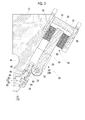
- Figs. 5A and 5B are views illustrating the arrangement and configuration of the die lip driving unit and a resin transporting mechanism.
- Fig. 5A illustrates a case where the die lip driving unit of this embodiment is employed
- Fig. 5B illustrates a case where a die lip driving unit according to a comparative example is employed.
- a lever and a flexible lip portion come into contact with each other and are attached to each other without an operating rod interposed therebetween.
- the T-die 10 of this embodiment is installed in the laminator and drops the molten resin extruded from the extruder (not illustrated) from the gap between the movable lip 16 (the flexible lip portion 22) and the fixed lip 18. As illustrated in Fig. 5A , the T-die 10 allows a film-like molten resin to be derived toward a nip portion 84 between a forming roll 80 and a nip roll 82 provided on the lower side thereof. A base material sheet is transported to the nip portion 84 from a separate transport path. The molten resin and the base material sheet are nipped between the nip roll 82 and the forming roll 80 and are pressed against each other, thereby forming a laminate film. The laminate film is wound around the forming roll 80 and cooled, and is thereafter guided to the downstream side in the transport direction thereof.
- the rotational force of the lever 34 is converted into the force of the operating rod 36 in the axial direction thereof, and the driving force in the direction along the side surface of the die body 12 is applied to the flexible lip portion 22.
- the point of action of the lever 34 is positioned closer to the die body 12 side than the rotating shaft 32 is. Therefore, as illustrated in the figure, the point of action P of the lever 34 can be set to a relatively high position.
- the rotating shaft 32 can be disposed at a higher position distant from the flexible lip portion 22.
- an air gap G between the outflow port of the resin in the T-die 10 and the nip portion 84 can be reduced. This means that a shrinkage phenomenon (neck-in) that may occur at both ends of the resin film in the air gap G can be suppressed and thus losses due to trimming after the formation can be reduced, that is, the product effective width can be increased.
- the tip end surface of a pressure-receiving portion that extends from a flexible lip portion 122 in a horizontal direction and the tip end of a transmission member 140 fixed to the lever 34 come into contact with each other. Accordingly, a configuration is employed in which the rotational force of the lever 34 is directly transmitted to the flexible lip portion 122.
- the point of action P of the lever 34 is set to be a position below the rotating shaft 32. As a result, the point of action of the lever 34 is at a position farther from the die body 12 than the rotating shaft 32. In this configuration, the air gap G has to be increased in order to avoid interference between the die lip driving unit and the nip roll 82.
- the space between the rotating shaft 32 and the nip roll 82 can be reduced as much as possible, and accordingly, the air gap G can be reduced.
- the yield of the resin film sent out from the T-die 10 is higher compared with that of the comparative example.
- the driving force of the actuator 24 can be efficiently transmitted to the flexible lip portion 22.
- the point of action of the lever 34 can be set to a high position. Accordingly, the air gap G between the resin outflow port in the die body 12 and the resin transportingmechanism (the rolls and the like) can be reduced, and thus the yield during the resin film formation can be enhanced.
- a die lip driving structure according to this embodiment is the same as that of the first embodiment except for the connection structure of an operating rod and a flexible lip portion. Therefore, like constituent elements similar to those of the first embodiment are denoted by like reference numerals, and the description thereof will be omitted.
- Fig. 6 is a partial enlarged sectional view illustrating the configuration of a die lip driving mechanism according to the second embodiment.
- a male screw portion 240 is provided in the lower portion of an operating rod 236.
- a nut 242 is fastened to the base end portion of the male screw portion 240.
- a connection member 238 has a U-shaped longitudinal section, and through the upper portion thereof, a female screw portion 244 which can be fastened to the male screw portion 240 penetrates.
- a die lip driving structure according to this embodiment is the same as that of the second embodiment except for the connection structure of an operating rod and a flexible lip portion. Therefore, like constituent elements similar to those of the second embodiment are denoted by like reference numerals, and the description thereof will be omitted.
- Fig. 7 is a partial enlarged sectional view illustrating the configuration of a die lip driving mechanism according to the third embodiment.
- the male screw portion 240 is provided in the lower portion of an operating rod 336, and the nut 242 is fastened to the base end portion of the male screw portion 240.
- a female screw portion 344 is provided in the pressure-receiving surface 23 of the flexible lip portion 22 and is configured so that the male screw portion 240 is screwed thereto in the axial direction.
- the operating rod 336 and the flexible lip portion 22 can be directly connected to each other.
- the operating rod 336 and the flexible lip portion 22 can be firmly fixed to each other.
- the positional relationship between the operating rod 336 and the lever 34 can be set with high precision. That is, the direction of the rotational force of the lever 34 at the point of action P can be allowed to be coincident with the axial direction of the operating rod 336.
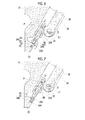
- a die lip driving structure according to this embodiment is the same as that of the first embodiment except for the connection structure of an operating rod and a lever.
- Fig. 8 is a partial enlarged sectional view illustrating the configuration of a die lip driving mechanism according to the fourth embodiment.
- a narrowed portion 444 is formed between the upper end of the operating rod 436 and the head portion of the screw 420.
- the connection portion 62 of the lever 34 is assembled to the narrowed portion 444.
- a process for forming a narrowed portion 44 on the outer peripheral surface of the operating rod 36 as in the first embodiment becomes unnecessary. Since the narrowed portion 444 is a point that forms the point of action P and thus requires high precision, manufacturing cost can be reduced by omitting a cutting process and the like.
- by increasing the fastening strength of the screw 420 it is possible to strongly connect the operating rod 436 and the lever 34 to each other.
- a die lip driving structure according to this embodiment is the same as that of the first embodiment except for the connection structure of an operating rod and a lever.
- Figs. 9A and 9B are views illustrating the configuration of a die lip driving mechanism according to the fifth embodiment.
- Fig. 9A is a partial enlarged sectional view illustrating the connection portion of the operating rod and the lever and the peripheral structure thereof, and
- Fig. 9B is a front view of the operating rod.
- a fork-shaped arm portion 540 is provided in the upper end portion of an operating rod 536, and a rotating shaft 544 is provided to cross the arm portion 540.
- a connection portion 562 of the lever 534 does not have a fork-shape unlike the first embodiment and extends in a flange shape, and the center portion thereof is provided with through-holes 546 through which the rotating shaft 544 is inserted.
- the connection portion 562 is rotatably connected to the rotating shaft 544. In this configuration, the position of the rotating shaft 544 becomes the point of action of the lever 534.
- the lever 534 can be relatively rotated about the connection portion of the lever 534 and the operating rod 536, and thus there is an advantage that an excessive load exerted on the point of action P when the operating rod 536 is relatively largely displaced can be prevented.
- the configuration in which both a tensile load and a pressing load can be applied to the flexible lip portion by operating the lever and the operating rod by driving the actuator is employed. That is, the flexible lip portion can be expanded or can be narrowed from a neutral state of the die lip driving unit.
- a configuration in which only one of a tensile load and a pressing load can be applied to the flexible lip portion is employed such that only one of the expanding operation and the narrowing operation of the flexible lip portion can be performed.
- one end side of the operating rod 36 may be connected to apply a biasing force (driving force) in only one of a pressing direction and a pulling direction to the flexible lip portion 22. In this case, when the biasing force applied via the operating rod 36 is released, the flexible lip portion 22 may be allowed to return to a state before the biasing force is applied, due to the elasticity thereof.
- the pneumatic drive type actuator 24 is employed, and the configuration in which when compressed air is supplied to one of the bellows 70 and 72, the other is opened to the air is exemplified.
- a configuration in which compressed air is supplied to both the bellows 70 and 72 and generates a pressure difference therebetween such that a tensile load or a pressing load is applied to the flexible lip portion may be employed.
- a pressure difference may be generated by providing individual pressure regulating valves in the bellows 70 and 72.
- the configuration in which the bellows 70 for pulling and the bellows 72 for pressing are respectively provided on both sides of the single lever is exemplified.
- a configuration in which a single bellows is provided to only one side of a single lever and the lever is operated in a pulling direction or a pressing direction by increasing or reducing the pressure of the bellows maybe employed.
- the pneumatic drive type actuator 24 is employed.
- a water pressure or oil pressure drive type actuator may also be employed.
- a circular type bellows is exemplified.
- a rectangular shape or other shapes may also be employed.
- a motor drive type actuator or other types of actuators may also be employed. Otherwise, the lever may also be manually operated without providing an actuator.
- the above-described die lip driving structure is applied to a laminator die, but may also be applied to dies for other applications including a film forming die and a sheet forming die, for example, a coater die, and a solvent casting die.
- the die lip driving structure is applied to the T-die, but may also be applied to a circular die for a blown film.
- the configuration in which the operating rod 36 is supported by the bearing member 40 is illustrated.
- the bearing member 40 may be omitted.
- the bearing member 40 may also be applied in the same manner in other embodiments.
Applications Claiming Priority (1)
| Application Number | Priority Date | Filing Date | Title |
|---|---|---|---|
| JP2014159643A JP6399850B2 (ja) | 2014-08-05 | 2014-08-05 | ダイリップ駆動構造 |
Publications (3)
| Publication Number | Publication Date |
|---|---|
| EP2982489A2 true EP2982489A2 (de) | 2016-02-10 |
| EP2982489A3 EP2982489A3 (de) | 2016-03-09 |
| EP2982489B1 EP2982489B1 (de) | 2018-10-24 |
Family
ID=53835884
Family Applications (1)
| Application Number | Title | Priority Date | Filing Date |
|---|---|---|---|
| EP15178406.3A Active EP2982489B1 (de) | 2014-08-05 | 2015-07-27 | Antriebsystem für die lippe einer düse |
Country Status (6)
| Country | Link |
|---|---|
| US (1) | US9700911B2 (de) |
| EP (1) | EP2982489B1 (de) |
| JP (1) | JP6399850B2 (de) |
| KR (1) | KR101764003B1 (de) |
| CN (1) | CN105313300B (de) |
| TW (1) | TWI644783B (de) |
Families Citing this family (14)
| Publication number | Priority date | Publication date | Assignee | Title |
|---|---|---|---|---|
| JP6913024B2 (ja) | 2015-11-27 | 2021-08-04 | 住友重機械モダン株式会社 | フィルム成形装置 |
| DE102016007363B4 (de) * | 2016-06-16 | 2018-03-08 | Wolfgang Hausmann | Querschnittsveränderungseinrichtung einer Spendeeinrichtung für eine Vorrichtung zur Folienherstellung |
| US11426914B2 (en) * | 2019-03-15 | 2022-08-30 | The Japan Steel Works, Ltd. | Resin film manufacturing device and resin film manufacturing method |
| JP7329832B2 (ja) * | 2019-10-31 | 2023-08-21 | 株式会社城北精工所 | 押出成形用ダイ |
| JP7412311B2 (ja) | 2020-09-18 | 2024-01-12 | 株式会社吉野工業所 | ヒンジキャップ |
| WO2022123294A1 (en) | 2020-12-09 | 2022-06-16 | 3M Innovative Properties Company | Method and system for adjusting a slot die used for making an extruded article |
| WO2022123295A1 (en) | 2020-12-09 | 2022-06-16 | 3M Innovative Properties Company | Method and system for adjusting a slot die used for making an extruded article |
| WO2022123296A1 (en) | 2020-12-09 | 2022-06-16 | 3M Innovative Properties Company | Slot die position adjustment with ringing constraint |
| JP2023553102A (ja) | 2020-12-09 | 2023-12-20 | スリーエム イノベイティブ プロパティズ カンパニー | スロットダイ位置調整 |
| JPWO2022130903A1 (de) | 2020-12-18 | 2022-06-23 | ||
| EP4309871A1 (de) * | 2021-03-16 | 2024-01-24 | The Japan Steel Works, Ltd. | Lippenabstandseinstellvorrichtung, extrusionsformwerkzeug, extrusionsformungsvorrichtung, lippenabstandseinstellverfahren und folienherstellungsverfahren |
| JP2024511228A (ja) | 2021-04-16 | 2024-03-12 | スリーエム イノベイティブ プロパティズ カンパニー | ハイブリッド制御によるスロットダイ調整 |
| CN113334730B (zh) * | 2021-08-05 | 2021-10-19 | 昌邑市永富弹簧有限公司 | 一种洗衣机减震组件生产用橡胶条预成型装置 |
| WO2023059333A1 (en) | 2021-10-08 | 2023-04-13 | 3M Innovative Properties Company | Slot die assembly with tuned stiffness, reduced draw zone, and force budget |
Citations (1)
| Publication number | Priority date | Publication date | Assignee | Title |
|---|---|---|---|---|
| JP2010247343A (ja) | 2009-04-10 | 2010-11-04 | Sumitomo Heavy Industries Modern Ltd | Tダイ用リップ駆動部 |
Family Cites Families (17)
| Publication number | Priority date | Publication date | Assignee | Title |
|---|---|---|---|---|
| GB1502267A (en) * | 1974-06-06 | 1978-03-01 | Agfa Gevaert | Extrusion dies in which at least one lip of the die orifice is adjustable |
| JPS5983622A (ja) * | 1982-11-05 | 1984-05-15 | Toshiba Mach Co Ltd | プラスチツクフイルム又はシ−ト成形用ダイのダイスリツト間隙制御装置 |
| JPS612522A (ja) * | 1984-06-16 | 1986-01-08 | Kazuo Tanimoto | プラスチツクシ−ト,フイルム用押出金型 |
| DE3731961A1 (de) * | 1987-09-23 | 1989-04-06 | Hoechst Ag | Vorrichtung zur spalteinstellung einer duese |
| JP3109034B2 (ja) * | 1992-04-15 | 2000-11-13 | 住友重機械プラスチックマシナリー株式会社 | Tダイリップ駆動部の構造 |
| JP2538482B2 (ja) * | 1992-04-20 | 1996-09-25 | バンドー化学株式会社 | Tダイのリップ間隔調整装置 |
| JP2996882B2 (ja) * | 1994-10-20 | 2000-01-11 | 東芝機械株式会社 | 熱変位式tダイ |
| US6017207A (en) * | 1996-09-24 | 2000-01-25 | Cloeren Incorporated | Apparatus for adjusting die lip gap |
| JP3315077B2 (ja) * | 1998-03-26 | 2002-08-19 | 住友重機械工業株式会社 | Tダイリップ駆動制御装置 |
| JP2001277331A (ja) | 2000-03-31 | 2001-10-09 | Toshiba Mach Co Ltd | Tダイのリップ隙間調整装置 |
| JP2001293767A (ja) * | 2000-04-11 | 2001-10-23 | Toshiba Mach Co Ltd | Tダイのリップ隙間調整装置 |
| US6663375B1 (en) * | 2000-06-19 | 2003-12-16 | Extrusion Dies, Inc. | Dual flexible lip extrusion apparatus with pivoting actuation member |
| JP2009247344A (ja) | 2008-04-08 | 2009-10-29 | Hidenari Honda | クイルカッター |
| JP2009247345A (ja) | 2008-04-09 | 2009-10-29 | Suiken Create Kk | 養液栽培方法及び養液栽培装置 |
| JP5220678B2 (ja) | 2009-04-10 | 2013-06-26 | 住友重機械モダン株式会社 | Tダイ用リップ駆動部 |
| JP5280285B2 (ja) | 2009-04-10 | 2013-09-04 | 住友重機械モダン株式会社 | Tダイ用リップ駆動部 |
| US8506280B1 (en) * | 2010-11-23 | 2013-08-13 | Allied Dies, Inc. | Lip adjustment system having cross-bar |
-
2014
- 2014-08-05 JP JP2014159643A patent/JP6399850B2/ja active Active
-
2015
- 2015-06-30 TW TW104121149A patent/TWI644783B/zh active
- 2015-07-06 KR KR1020150095723A patent/KR101764003B1/ko active IP Right Grant
- 2015-07-07 CN CN201510393819.3A patent/CN105313300B/zh active Active
- 2015-07-27 EP EP15178406.3A patent/EP2982489B1/de active Active
- 2015-07-28 US US14/811,691 patent/US9700911B2/en active Active
Patent Citations (1)
| Publication number | Priority date | Publication date | Assignee | Title |
|---|---|---|---|---|
| JP2010247343A (ja) | 2009-04-10 | 2010-11-04 | Sumitomo Heavy Industries Modern Ltd | Tダイ用リップ駆動部 |
Also Published As
| Publication number | Publication date |
|---|---|
| JP2016036926A (ja) | 2016-03-22 |
| TWI644783B (zh) | 2018-12-21 |
| US20160038964A1 (en) | 2016-02-11 |
| TW201605603A (zh) | 2016-02-16 |
| EP2982489B1 (de) | 2018-10-24 |
| CN105313300A (zh) | 2016-02-10 |
| CN105313300B (zh) | 2018-11-30 |
| JP6399850B2 (ja) | 2018-10-03 |
| KR20160016595A (ko) | 2016-02-15 |
| EP2982489A3 (de) | 2016-03-09 |
| KR101764003B1 (ko) | 2017-08-01 |
| US9700911B2 (en) | 2017-07-11 |
Similar Documents
| Publication | Publication Date | Title |
|---|---|---|
| US9700911B2 (en) | Die lip driving structure | |
| US8491296B2 (en) | Lip drive part for T-die | |
| US10156295B2 (en) | Piezoelectric linear actuator, piezoelectrically driven valve, and flow rate control device | |
| WO2006060619A3 (en) | Pressure control valve having intrinsic mechanical feedback system | |
| US10724644B2 (en) | Fluid control valve | |
| JP6913024B2 (ja) | フィルム成形装置 | |
| CN105313292B (zh) | 具有定幅系统的多歧管挤出模具及其使用方法 | |
| US9841771B2 (en) | Pressure-reducing valve | |
| JP4716879B2 (ja) | 押出成形用tダイ | |
| WO2019097863A1 (ja) | 間欠塗布装置 | |
| JP5498826B2 (ja) | コーティングダイ | |
| US9694530B2 (en) | Extrusion die tension adjuster and method of using same | |
| JP5554006B2 (ja) | Tダイ用リップ駆動部 | |
| KR102308263B1 (ko) | 압출 성형용 플랫 다이 및 필름 성형 방법 | |
| JP5361771B2 (ja) | エクストルージョン塗布方法及び塗布フィルムの製造方法 | |
| US20210215214A1 (en) | Brake device | |
| US20100230869A1 (en) | Vacuum press machine and vacuum press method | |
| US11035493B2 (en) | Controller | |
| JP2011218651A (ja) | 押出成形用フラットダイ | |
| JP2018122269A (ja) | ダイ及び塗布方法 | |
| JP6676456B2 (ja) | スリッタ装置におけるカッタ装置 | |
| EP3575059A1 (de) | Extrusionsdüse und extrusionsverfahren ffür eine folie damit | |
| JP2006009658A (ja) | スロットルバルブ全閉時の空気流量調節構造および方法 |
Legal Events
| Date | Code | Title | Description |
|---|---|---|---|
| PUAL | Search report despatched |
Free format text: ORIGINAL CODE: 0009013 |
|
| PUAI | Public reference made under article 153(3) epc to a published international application that has entered the european phase |
Free format text: ORIGINAL CODE: 0009012 |
|
| 17P | Request for examination filed |
Effective date: 20150727 |
|
| AK | Designated contracting states |
Kind code of ref document: A2 Designated state(s): AL AT BE BG CH CY CZ DE DK EE ES FI FR GB GR HR HU IE IS IT LI LT LU LV MC MK MT NL NO PL PT RO RS SE SI SK SM TR |
|
| AX | Request for extension of the european patent |
Extension state: BA ME |
|
| AK | Designated contracting states |
Kind code of ref document: A3 Designated state(s): AL AT BE BG CH CY CZ DE DK EE ES FI FR GB GR HR HU IE IS IT LI LT LU LV MC MK MT NL NO PL PT RO RS SE SI SK SM TR |
|
| AX | Request for extension of the european patent |
Extension state: BA ME |
|
| RIC1 | Information provided on ipc code assigned before grant |
Ipc: B29C 47/08 20060101ALN20160203BHEP Ipc: B29C 47/92 20060101ALI20160203BHEP Ipc: B29C 47/16 20060101AFI20160203BHEP Ipc: B29C 47/18 20060101ALN20160203BHEP |
|
| 17Q | First examination report despatched |
Effective date: 20160304 |
|
| GRAP | Despatch of communication of intention to grant a patent |
Free format text: ORIGINAL CODE: EPIDOSNIGR1 |
|
| STAA | Information on the status of an ep patent application or granted ep patent |
Free format text: STATUS: GRANT OF PATENT IS INTENDED |
|
| RIC1 | Information provided on ipc code assigned before grant |
Ipc: B29C 47/16 20060101AFI20180417BHEP Ipc: B29C 47/92 20060101ALI20180417BHEP Ipc: B29C 47/08 20060101ALN20180417BHEP Ipc: B29C 47/18 20060101ALN20180417BHEP |
|
| INTG | Intention to grant announced |
Effective date: 20180508 |
|
| RIC1 | Information provided on ipc code assigned before grant |
Ipc: B29C 47/08 20060101ALN20180424BHEP Ipc: B29C 47/18 20060101ALN20180424BHEP Ipc: B29C 47/16 20060101AFI20180424BHEP Ipc: B29C 47/92 20060101ALI20180424BHEP |
|
| GRAS | Grant fee paid |
Free format text: ORIGINAL CODE: EPIDOSNIGR3 |
|
| GRAA | (expected) grant |
Free format text: ORIGINAL CODE: 0009210 |
|
| STAA | Information on the status of an ep patent application or granted ep patent |
Free format text: STATUS: THE PATENT HAS BEEN GRANTED |
|
| AK | Designated contracting states |
Kind code of ref document: B1 Designated state(s): AL AT BE BG CH CY CZ DE DK EE ES FI FR GB GR HR HU IE IS IT LI LT LU LV MC MK MT NL NO PL PT RO RS SE SI SK SM TR |
|
| RAP1 | Party data changed (applicant data changed or rights of an application transferred) |
Owner name: SUMITOMO HEAVY INDUSTRIES MODERN, LTD. |
|
| REG | Reference to a national code |
Ref country code: CH Ref legal event code: EP |
|
| REG | Reference to a national code |
Ref country code: IE Ref legal event code: FG4D |
|
| REG | Reference to a national code |
Ref country code: AT Ref legal event code: REF Ref document number: 1056150 Country of ref document: AT Kind code of ref document: T Effective date: 20181115 |
|
| REG | Reference to a national code |
Ref country code: DE Ref legal event code: R096 Ref document number: 602015018588 Country of ref document: DE |
|
| REG | Reference to a national code |
Ref country code: DE Ref legal event code: R079 Ref document number: 602015018588 Country of ref document: DE Free format text: PREVIOUS MAIN CLASS: B29C0047160000 Ipc: B29C0048310000 |
|
| REG | Reference to a national code |
Ref country code: NL Ref legal event code: MP Effective date: 20181024 |
|
| REG | Reference to a national code |
Ref country code: LT Ref legal event code: MG4D |
|
| PG25 | Lapsed in a contracting state [announced via postgrant information from national office to epo] |
Ref country code: NL Free format text: LAPSE BECAUSE OF FAILURE TO SUBMIT A TRANSLATION OF THE DESCRIPTION OR TO PAY THE FEE WITHIN THE PRESCRIBED TIME-LIMIT Effective date: 20181024 |
|
| PG25 | Lapsed in a contracting state [announced via postgrant information from national office to epo] |
Ref country code: IS Free format text: LAPSE BECAUSE OF FAILURE TO SUBMIT A TRANSLATION OF THE DESCRIPTION OR TO PAY THE FEE WITHIN THE PRESCRIBED TIME-LIMIT Effective date: 20190224 Ref country code: FI Free format text: LAPSE BECAUSE OF FAILURE TO SUBMIT A TRANSLATION OF THE DESCRIPTION OR TO PAY THE FEE WITHIN THE PRESCRIBED TIME-LIMIT Effective date: 20181024 Ref country code: BG Free format text: LAPSE BECAUSE OF FAILURE TO SUBMIT A TRANSLATION OF THE DESCRIPTION OR TO PAY THE FEE WITHIN THE PRESCRIBED TIME-LIMIT Effective date: 20190124 Ref country code: PL Free format text: LAPSE BECAUSE OF FAILURE TO SUBMIT A TRANSLATION OF THE DESCRIPTION OR TO PAY THE FEE WITHIN THE PRESCRIBED TIME-LIMIT Effective date: 20181024 Ref country code: HR Free format text: LAPSE BECAUSE OF FAILURE TO SUBMIT A TRANSLATION OF THE DESCRIPTION OR TO PAY THE FEE WITHIN THE PRESCRIBED TIME-LIMIT Effective date: 20181024 Ref country code: LV Free format text: LAPSE BECAUSE OF FAILURE TO SUBMIT A TRANSLATION OF THE DESCRIPTION OR TO PAY THE FEE WITHIN THE PRESCRIBED TIME-LIMIT Effective date: 20181024 Ref country code: ES Free format text: LAPSE BECAUSE OF FAILURE TO SUBMIT A TRANSLATION OF THE DESCRIPTION OR TO PAY THE FEE WITHIN THE PRESCRIBED TIME-LIMIT Effective date: 20181024 Ref country code: LT Free format text: LAPSE BECAUSE OF FAILURE TO SUBMIT A TRANSLATION OF THE DESCRIPTION OR TO PAY THE FEE WITHIN THE PRESCRIBED TIME-LIMIT Effective date: 20181024 Ref country code: NO Free format text: LAPSE BECAUSE OF FAILURE TO SUBMIT A TRANSLATION OF THE DESCRIPTION OR TO PAY THE FEE WITHIN THE PRESCRIBED TIME-LIMIT Effective date: 20190124 |
|
| PG25 | Lapsed in a contracting state [announced via postgrant information from national office to epo] |
Ref country code: PT Free format text: LAPSE BECAUSE OF FAILURE TO SUBMIT A TRANSLATION OF THE DESCRIPTION OR TO PAY THE FEE WITHIN THE PRESCRIBED TIME-LIMIT Effective date: 20190224 Ref country code: GR Free format text: LAPSE BECAUSE OF FAILURE TO SUBMIT A TRANSLATION OF THE DESCRIPTION OR TO PAY THE FEE WITHIN THE PRESCRIBED TIME-LIMIT Effective date: 20190125 Ref country code: RS Free format text: LAPSE BECAUSE OF FAILURE TO SUBMIT A TRANSLATION OF THE DESCRIPTION OR TO PAY THE FEE WITHIN THE PRESCRIBED TIME-LIMIT Effective date: 20181024 Ref country code: AL Free format text: LAPSE BECAUSE OF FAILURE TO SUBMIT A TRANSLATION OF THE DESCRIPTION OR TO PAY THE FEE WITHIN THE PRESCRIBED TIME-LIMIT Effective date: 20181024 Ref country code: SE Free format text: LAPSE BECAUSE OF FAILURE TO SUBMIT A TRANSLATION OF THE DESCRIPTION OR TO PAY THE FEE WITHIN THE PRESCRIBED TIME-LIMIT Effective date: 20181024 |
|
| REG | Reference to a national code |
Ref country code: DE Ref legal event code: R097 Ref document number: 602015018588 Country of ref document: DE |
|
| PG25 | Lapsed in a contracting state [announced via postgrant information from national office to epo] |
Ref country code: CZ Free format text: LAPSE BECAUSE OF FAILURE TO SUBMIT A TRANSLATION OF THE DESCRIPTION OR TO PAY THE FEE WITHIN THE PRESCRIBED TIME-LIMIT Effective date: 20181024 Ref country code: DK Free format text: LAPSE BECAUSE OF FAILURE TO SUBMIT A TRANSLATION OF THE DESCRIPTION OR TO PAY THE FEE WITHIN THE PRESCRIBED TIME-LIMIT Effective date: 20181024 |
|
| PG25 | Lapsed in a contracting state [announced via postgrant information from national office to epo] |
Ref country code: SK Free format text: LAPSE BECAUSE OF FAILURE TO SUBMIT A TRANSLATION OF THE DESCRIPTION OR TO PAY THE FEE WITHIN THE PRESCRIBED TIME-LIMIT Effective date: 20181024 Ref country code: SM Free format text: LAPSE BECAUSE OF FAILURE TO SUBMIT A TRANSLATION OF THE DESCRIPTION OR TO PAY THE FEE WITHIN THE PRESCRIBED TIME-LIMIT Effective date: 20181024 Ref country code: EE Free format text: LAPSE BECAUSE OF FAILURE TO SUBMIT A TRANSLATION OF THE DESCRIPTION OR TO PAY THE FEE WITHIN THE PRESCRIBED TIME-LIMIT Effective date: 20181024 Ref country code: RO Free format text: LAPSE BECAUSE OF FAILURE TO SUBMIT A TRANSLATION OF THE DESCRIPTION OR TO PAY THE FEE WITHIN THE PRESCRIBED TIME-LIMIT Effective date: 20181024 |
|
| PLBE | No opposition filed within time limit |
Free format text: ORIGINAL CODE: 0009261 |
|
| STAA | Information on the status of an ep patent application or granted ep patent |
Free format text: STATUS: NO OPPOSITION FILED WITHIN TIME LIMIT |
|
| 26N | No opposition filed |
Effective date: 20190725 |
|
| PG25 | Lapsed in a contracting state [announced via postgrant information from national office to epo] |
Ref country code: SI Free format text: LAPSE BECAUSE OF FAILURE TO SUBMIT A TRANSLATION OF THE DESCRIPTION OR TO PAY THE FEE WITHIN THE PRESCRIBED TIME-LIMIT Effective date: 20181024 |
|
| PG25 | Lapsed in a contracting state [announced via postgrant information from national office to epo] |
Ref country code: MC Free format text: LAPSE BECAUSE OF FAILURE TO SUBMIT A TRANSLATION OF THE DESCRIPTION OR TO PAY THE FEE WITHIN THE PRESCRIBED TIME-LIMIT Effective date: 20181024 |
|
| REG | Reference to a national code |
Ref country code: CH Ref legal event code: PL |
|
| GBPC | Gb: european patent ceased through non-payment of renewal fee |
Effective date: 20190727 |
|
| PG25 | Lapsed in a contracting state [announced via postgrant information from national office to epo] |
Ref country code: TR Free format text: LAPSE BECAUSE OF FAILURE TO SUBMIT A TRANSLATION OF THE DESCRIPTION OR TO PAY THE FEE WITHIN THE PRESCRIBED TIME-LIMIT Effective date: 20181024 |
|
| PG25 | Lapsed in a contracting state [announced via postgrant information from national office to epo] |
Ref country code: GB Free format text: LAPSE BECAUSE OF NON-PAYMENT OF DUE FEES Effective date: 20190727 |
|
| PG25 | Lapsed in a contracting state [announced via postgrant information from national office to epo] |
Ref country code: LU Free format text: LAPSE BECAUSE OF NON-PAYMENT OF DUE FEES Effective date: 20190727 Ref country code: CH Free format text: LAPSE BECAUSE OF NON-PAYMENT OF DUE FEES Effective date: 20190731 Ref country code: LI Free format text: LAPSE BECAUSE OF NON-PAYMENT OF DUE FEES Effective date: 20190731 |
|
| PG25 | Lapsed in a contracting state [announced via postgrant information from national office to epo] |
Ref country code: FR Free format text: LAPSE BECAUSE OF NON-PAYMENT OF DUE FEES Effective date: 20190731 |
|
| PG25 | Lapsed in a contracting state [announced via postgrant information from national office to epo] |
Ref country code: IE Free format text: LAPSE BECAUSE OF NON-PAYMENT OF DUE FEES Effective date: 20190727 |
|
| PG25 | Lapsed in a contracting state [announced via postgrant information from national office to epo] |
Ref country code: CY Free format text: LAPSE BECAUSE OF FAILURE TO SUBMIT A TRANSLATION OF THE DESCRIPTION OR TO PAY THE FEE WITHIN THE PRESCRIBED TIME-LIMIT Effective date: 20181024 |
|
| REG | Reference to a national code |
Ref country code: AT Ref legal event code: UEP Ref document number: 1056150 Country of ref document: AT Kind code of ref document: T Effective date: 20181024 |
|
| PG25 | Lapsed in a contracting state [announced via postgrant information from national office to epo] |
Ref country code: MT Free format text: LAPSE BECAUSE OF FAILURE TO SUBMIT A TRANSLATION OF THE DESCRIPTION OR TO PAY THE FEE WITHIN THE PRESCRIBED TIME-LIMIT Effective date: 20181024 Ref country code: HU Free format text: LAPSE BECAUSE OF FAILURE TO SUBMIT A TRANSLATION OF THE DESCRIPTION OR TO PAY THE FEE WITHIN THE PRESCRIBED TIME-LIMIT; INVALID AB INITIO Effective date: 20150727 |
|
| PG25 | Lapsed in a contracting state [announced via postgrant information from national office to epo] |
Ref country code: MK Free format text: LAPSE BECAUSE OF FAILURE TO SUBMIT A TRANSLATION OF THE DESCRIPTION OR TO PAY THE FEE WITHIN THE PRESCRIBED TIME-LIMIT Effective date: 20181024 |
|
| PGFP | Annual fee paid to national office [announced via postgrant information from national office to epo] |
Ref country code: IT Payment date: 20230612 Year of fee payment: 9 |
|
| PGFP | Annual fee paid to national office [announced via postgrant information from national office to epo] |
Ref country code: BE Payment date: 20230616 Year of fee payment: 9 |
|
| PGFP | Annual fee paid to national office [announced via postgrant information from national office to epo] |
Ref country code: AT Payment date: 20230626 Year of fee payment: 9 |
|
| PGFP | Annual fee paid to national office [announced via postgrant information from national office to epo] |
Ref country code: DE Payment date: 20230531 Year of fee payment: 9 |