EP2752216A1 - Spendervorrichtung - Google Patents
Spendervorrichtung Download PDFInfo
- Publication number
- EP2752216A1 EP2752216A1 EP14162934.5A EP14162934A EP2752216A1 EP 2752216 A1 EP2752216 A1 EP 2752216A1 EP 14162934 A EP14162934 A EP 14162934A EP 2752216 A1 EP2752216 A1 EP 2752216A1
- Authority
- EP
- European Patent Office
- Prior art keywords
- powder
- carrier
- counter
- counter ring
- Prior art date
- Legal status (The legal status is an assumption and is not a legal conclusion. Google has not performed a legal analysis and makes no representation as to the accuracy of the status listed.)
- Granted
Links
Images


Classifications
-
- A—HUMAN NECESSITIES
- A61—MEDICAL OR VETERINARY SCIENCE; HYGIENE
- A61M—DEVICES FOR INTRODUCING MEDIA INTO, OR ONTO, THE BODY; DEVICES FOR TRANSDUCING BODY MEDIA OR FOR TAKING MEDIA FROM THE BODY; DEVICES FOR PRODUCING OR ENDING SLEEP OR STUPOR
- A61M15/00—Inhalators
- A61M15/0065—Inhalators with dosage or measuring devices
- A61M15/0068—Indicating or counting the number of dispensed doses or of remaining doses
- A61M15/007—Mechanical counters
- A61M15/0071—Mechanical counters having a display or indicator
- A61M15/0073—Mechanical counters having a display or indicator on a ring
-
- A—HUMAN NECESSITIES
- A61—MEDICAL OR VETERINARY SCIENCE; HYGIENE
- A61J—CONTAINERS SPECIALLY ADAPTED FOR MEDICAL OR PHARMACEUTICAL PURPOSES; DEVICES OR METHODS SPECIALLY ADAPTED FOR BRINGING PHARMACEUTICAL PRODUCTS INTO PARTICULAR PHYSICAL OR ADMINISTERING FORMS; DEVICES FOR ADMINISTERING FOOD OR MEDICINES ORALLY; BABY COMFORTERS; DEVICES FOR RECEIVING SPITTLE
- A61J3/00—Devices or methods specially adapted for bringing pharmaceutical products into particular physical or administering forms
- A61J3/02—Devices or methods specially adapted for bringing pharmaceutical products into particular physical or administering forms into the form of powders
-
- A—HUMAN NECESSITIES
- A61—MEDICAL OR VETERINARY SCIENCE; HYGIENE
- A61M—DEVICES FOR INTRODUCING MEDIA INTO, OR ONTO, THE BODY; DEVICES FOR TRANSDUCING BODY MEDIA OR FOR TAKING MEDIA FROM THE BODY; DEVICES FOR PRODUCING OR ENDING SLEEP OR STUPOR
- A61M13/00—Insufflators for therapeutic or disinfectant purposes, i.e. devices for blowing a gas, powder or vapour into the body
-
- A—HUMAN NECESSITIES
- A61—MEDICAL OR VETERINARY SCIENCE; HYGIENE
- A61M—DEVICES FOR INTRODUCING MEDIA INTO, OR ONTO, THE BODY; DEVICES FOR TRANSDUCING BODY MEDIA OR FOR TAKING MEDIA FROM THE BODY; DEVICES FOR PRODUCING OR ENDING SLEEP OR STUPOR
- A61M15/00—Inhalators
-
- A—HUMAN NECESSITIES
- A61—MEDICAL OR VETERINARY SCIENCE; HYGIENE
- A61M—DEVICES FOR INTRODUCING MEDIA INTO, OR ONTO, THE BODY; DEVICES FOR TRANSDUCING BODY MEDIA OR FOR TAKING MEDIA FROM THE BODY; DEVICES FOR PRODUCING OR ENDING SLEEP OR STUPOR
- A61M15/00—Inhalators
- A61M15/0001—Details of inhalators; Constructional features thereof
- A61M15/0021—Mouthpieces therefor
- A61M15/0025—Mouthpieces therefor with caps
- A61M15/0026—Hinged caps
-
- A—HUMAN NECESSITIES
- A61—MEDICAL OR VETERINARY SCIENCE; HYGIENE
- A61M—DEVICES FOR INTRODUCING MEDIA INTO, OR ONTO, THE BODY; DEVICES FOR TRANSDUCING BODY MEDIA OR FOR TAKING MEDIA FROM THE BODY; DEVICES FOR PRODUCING OR ENDING SLEEP OR STUPOR
- A61M15/00—Inhalators
- A61M15/0028—Inhalators using prepacked dosages, one for each application, e.g. capsules to be perforated or broken-up
- A61M15/003—Inhalators using prepacked dosages, one for each application, e.g. capsules to be perforated or broken-up using capsules, e.g. to be perforated or broken-up
- A61M15/0031—Inhalators using prepacked dosages, one for each application, e.g. capsules to be perforated or broken-up using capsules, e.g. to be perforated or broken-up by bursting or breaking the package, i.e. without cutting or piercing
-
- A—HUMAN NECESSITIES
- A61—MEDICAL OR VETERINARY SCIENCE; HYGIENE
- A61M—DEVICES FOR INTRODUCING MEDIA INTO, OR ONTO, THE BODY; DEVICES FOR TRANSDUCING BODY MEDIA OR FOR TAKING MEDIA FROM THE BODY; DEVICES FOR PRODUCING OR ENDING SLEEP OR STUPOR
- A61M15/00—Inhalators
- A61M15/0028—Inhalators using prepacked dosages, one for each application, e.g. capsules to be perforated or broken-up
- A61M15/0045—Inhalators using prepacked dosages, one for each application, e.g. capsules to be perforated or broken-up using multiple prepacked dosages on a same carrier, e.g. blisters
- A61M15/0046—Inhalators using prepacked dosages, one for each application, e.g. capsules to be perforated or broken-up using multiple prepacked dosages on a same carrier, e.g. blisters characterized by the type of carrier
- A61M15/0048—Inhalators using prepacked dosages, one for each application, e.g. capsules to be perforated or broken-up using multiple prepacked dosages on a same carrier, e.g. blisters characterized by the type of carrier the dosages being arranged in a plane, e.g. on diskettes
-
- A—HUMAN NECESSITIES
- A61—MEDICAL OR VETERINARY SCIENCE; HYGIENE
- A61M—DEVICES FOR INTRODUCING MEDIA INTO, OR ONTO, THE BODY; DEVICES FOR TRANSDUCING BODY MEDIA OR FOR TAKING MEDIA FROM THE BODY; DEVICES FOR PRODUCING OR ENDING SLEEP OR STUPOR
- A61M15/00—Inhalators
- A61M15/0028—Inhalators using prepacked dosages, one for each application, e.g. capsules to be perforated or broken-up
- A61M15/0045—Inhalators using prepacked dosages, one for each application, e.g. capsules to be perforated or broken-up using multiple prepacked dosages on a same carrier, e.g. blisters
- A61M15/0053—Inhalators using prepacked dosages, one for each application, e.g. capsules to be perforated or broken-up using multiple prepacked dosages on a same carrier, e.g. blisters characterized by the type or way of disposal
- A61M15/0058—Inhalators using prepacked dosages, one for each application, e.g. capsules to be perforated or broken-up using multiple prepacked dosages on a same carrier, e.g. blisters characterized by the type or way of disposal the used dosages being cut from the carrier
-
- A—HUMAN NECESSITIES
- A61—MEDICAL OR VETERINARY SCIENCE; HYGIENE
- A61M—DEVICES FOR INTRODUCING MEDIA INTO, OR ONTO, THE BODY; DEVICES FOR TRANSDUCING BODY MEDIA OR FOR TAKING MEDIA FROM THE BODY; DEVICES FOR PRODUCING OR ENDING SLEEP OR STUPOR
- A61M15/00—Inhalators
- A61M15/0028—Inhalators using prepacked dosages, one for each application, e.g. capsules to be perforated or broken-up
- A61M15/0061—Inhalators using prepacked dosages, one for each application, e.g. capsules to be perforated or broken-up using pre-packed dosages having an insert inside
-
- A—HUMAN NECESSITIES
- A61—MEDICAL OR VETERINARY SCIENCE; HYGIENE
- A61M—DEVICES FOR INTRODUCING MEDIA INTO, OR ONTO, THE BODY; DEVICES FOR TRANSDUCING BODY MEDIA OR FOR TAKING MEDIA FROM THE BODY; DEVICES FOR PRODUCING OR ENDING SLEEP OR STUPOR
- A61M15/00—Inhalators
- A61M15/0065—Inhalators with dosage or measuring devices
- A61M15/0068—Indicating or counting the number of dispensed doses or of remaining doses
- A61M15/007—Mechanical counters
- A61M15/0071—Mechanical counters having a display or indicator
- A61M15/0075—Mechanical counters having a display or indicator on a disc
-
- B—PERFORMING OPERATIONS; TRANSPORTING
- B65—CONVEYING; PACKING; STORING; HANDLING THIN OR FILAMENTARY MATERIAL
- B65D—CONTAINERS FOR STORAGE OR TRANSPORT OF ARTICLES OR MATERIALS, e.g. BAGS, BARRELS, BOTTLES, BOXES, CANS, CARTONS, CRATES, DRUMS, JARS, TANKS, HOPPERS, FORWARDING CONTAINERS; ACCESSORIES, CLOSURES, OR FITTINGS THEREFOR; PACKAGING ELEMENTS; PACKAGES
- B65D83/00—Containers or packages with special means for dispensing contents
- B65D83/06—Containers or packages with special means for dispensing contents for dispensing powdered or granular material
-
- G—PHYSICS
- G06—COMPUTING; CALCULATING OR COUNTING
- G06M—COUNTING MECHANISMS; COUNTING OF OBJECTS NOT OTHERWISE PROVIDED FOR
- G06M1/00—Design features of general application
- G06M1/22—Design features of general application for visual indication of the result of count on counting mechanisms, e.g. by window with magnifying lens
- G06M1/24—Drums; Dials; Pointers
- G06M1/248—Discs
-
- A—HUMAN NECESSITIES
- A61—MEDICAL OR VETERINARY SCIENCE; HYGIENE
- A61M—DEVICES FOR INTRODUCING MEDIA INTO, OR ONTO, THE BODY; DEVICES FOR TRANSDUCING BODY MEDIA OR FOR TAKING MEDIA FROM THE BODY; DEVICES FOR PRODUCING OR ENDING SLEEP OR STUPOR
- A61M2202/00—Special media to be introduced, removed or treated
- A61M2202/06—Solids
- A61M2202/064—Powder
-
- B—PERFORMING OPERATIONS; TRANSPORTING
- B65—CONVEYING; PACKING; STORING; HANDLING THIN OR FILAMENTARY MATERIAL
- B65D—CONTAINERS FOR STORAGE OR TRANSPORT OF ARTICLES OR MATERIALS, e.g. BAGS, BARRELS, BOTTLES, BOXES, CANS, CARTONS, CRATES, DRUMS, JARS, TANKS, HOPPERS, FORWARDING CONTAINERS; ACCESSORIES, CLOSURES, OR FITTINGS THEREFOR; PACKAGING ELEMENTS; PACKAGES
- B65D83/00—Containers or packages with special means for dispensing contents
- B65D83/04—Containers or packages with special means for dispensing contents for dispensing annular, disc-shaped, or spherical or like small articles, e.g. tablets or pills
- B65D83/0445—Containers or packages with special means for dispensing contents for dispensing annular, disc-shaped, or spherical or like small articles, e.g. tablets or pills all the articles being stored in individual compartments
Definitions
- the present invention relates to a dispensing device, in particular for dispensing individual doses of powder from respective pockets of a carrier.
- a wide variety of devices are known for dispensing doses of medicament in the form of powder for inhalation.
- Devices which contain a store of powdered medicament from which individual doses are metered as required.
- Devices are also known which include carriers having a plurality of pockets containing respective doses of powder. These carriers are typically in the form of blister-packs. All of these devices face problems of providing reliable, repeatable and accurate inhaled amounts of powder.
- US 4,811,731 describes an inhaler having a support for a blister pack having an annular array of blisters.
- the support faces a tray having upstanding walls defining a flow path to a mouthpiece.
- the support and blister pack is consecutively indexed such that powder from respective blisters is dispensed via the flow path defined by the tray and upstanding walls. Because the same tray and upstanding walls are used for all of the blisters, there is the problem that powder can become adhered to the tray and upstanding walls and then dislodged subsequently.
- a device for dispensing individual doses of powder from respective pockets of a carrier including a support for a carrier having a plurality of pockets containing respective doses of powder and a mouthpiece through which to inhale an airstream carrying a dose of powder, the device further including walls for defining individual respective first flow paths downstream of each respective pocket of a supported carrier wherein each individual respective first flow path is defined entirely by respective walls unique to that individual respective first flow path, is for connecting the corresponding respective pocket to the mouthpiece and is for deaggregating powder in the airstream.
- each pocket of powder is provided with its own first flow path such that any powder which does adhere to the walls of that first flow path will not affect subsequent dispensing inhalations through the device.
- There are no walls in common between respective first flow paths such that powder adhering to walls of a first flow path will not affect subsequent doses.
- subsequent inhalations will draw airstreams through the first flow paths of the respective pockets being dispensed such that, even if previously adhered powder is dislodged in the first flow paths of previously dispensed pockets, this powder will not be part of the inhalation airstream and, hence, will not be inhaled by the user.
- a device for dispensing individual doses of powder from respective pockets of a carrier including: a support for a carrier having a plurality of pockets containing respective doses of powder; and a mouthpiece through which to inhale an airstream carrying a dose of powder; the device further including: walls for defining individual respective first flow paths downstream of each respective pocket of a supported carrier for connecting the corresponding respective pockets to the mouthpiece and deaggregating powder in the airstream; an arrangement for moving individually each pocket from a respective storage position to a respective discharge position, wherein each pocket, in the respective discharge position, forms an integral part of the individual respective first flow path.
- the device is for use with a carrier having pockets provided with a lidding sheet, the device allowing the lidding sheet to be ruptured as a consequence of moving a pocket from a respective storage position to a respective discharge position.
- the device further includes walls defining a second flow path connecting with the mouthpiece and bypassing the pockets.
- the device should preferably provide similar performance over flow rates ranging from 28.3 l/min to 60 l/min and should preferably have a pressure drop not exceeding 4 kPa at 60 l/min.
- the respective flow path connects with the second flow path downstream of the bypass and at an angle such that substantially no powder impacts with the walls defining the second flow path.
- Some impact could be allowed, but then preferably substantially no deposition occurs.
- Some powder could be allowed to be deposited on the walls defining the second flow path, but then preferably, with repeated use of the device and the second flow path, no more than 25% or preferably no more than 15% of a dose remains deposited on the walls defining the second flow path.
- the airstream through the second flow path also acts to scour or scavenge powder deposited on the walls defining the second flow path.
- the second flow path can be arranged to provide a minimum amount of turbulence and to avoid substantially any powder adhering to its walls.
- the angle is less than 45 degrees, more preferably less than 30 degrees.
- the support for the carrier and the walls defining the first flow path are moveable with a supported carrier so as to selectively connect respective first flow paths with the second flow path and, hence, selectively dispense doses of powder from respective pockets of the supported carrier.
- the device can be provided with a single mouthpiece and dispensing mechanism so as to minimise cost and complexity and yet still provide each pocket of the carrier with its own respective first flow path in which deaggregation and any adherence of powder occurs.
- the carriers are disc-shaped with a circumferential array of pockets.
- the pockets and their respective first flow paths are indexed by rotation relative to the second flow path and mouthpiece so as to dispense consecutively doses of powder for inhalation through the mouthpiece.
- the walls defining the first flow paths include, upstream of the pockets, respective portions of relatively reduced cross-sectional area orientated so as to be directed towards respective pockets and direct a relatively high velocity airstream into the respective pockets.
- a device for dispensing a dose of powder from a pocket of a carrier including a support for a carrier having a pocket containing a dose of powder and a mouthpiece through which to inhale an airstream carrying a dose of powder, the device further including walls defining first and second flow paths connecting with the mouthpiece, the first flow path connecting the pocket of the supported carrier to the mouthpiece and the second flow path bypassing the pocket, wherein the walls defining the first flow path include, upstream of the pocket, a portion of relatively reduced cross-sectional area orientated so as to be directed towards the pocket and direct a relatively high velocity airstream into the pocket.
- the high velocity airstream can erode the powder in the pocket so as to progressively entrain it into the airstream, rather than merely attempt to flush the powder from the pocket.
- the time is preferably within the range of 0.01 s to 1.0 s and more preferably in the range of 0.2 s to 0.5 s. This provides improved inhalation characteristics.
- the second flow path in conjunction with the first flow path, resistance to airflow can be reduced and volume of airflow increased.
- the portions of relatively reduced cross-sectional area produce a small high velocity stream suitable for eroding the powder.
- this arrangement has similar advantages when used with a carrier having only a single pocket and, hence, only a single first flow path.
- each portion has a cross-sectional area between 50% and 66% of the cross-sectional area of the smallest part of the second flow path.
- the cross-sectional areas of the non-reduced cross-section parts of each flow path are provided between 110% and 150% of the minimum values in their own path order to maintain the high air velocities required to keep the powder entrained without contributing significantly to pressure drop.
- a patient inhales through both second flow paths whilst drawing powder from the first flow path in use.
- Each of the second flow paths is expected to carry approximately 40% of the total inhaled air for an average use.
- the portion forming the inlet to the pocket can be small and, for a child or patient with COPD (Chronic Obstructive Pulmonary Disease), the total pressure drop should be low.
- COPD Chironic Obstructive Pulmonary Disease
- an inlet portion could be provided with a cross-sectional area of 2 mm 2 and a bypass second flow path with a minimum cross-sectional area of 8 mm 2 , resulting in a ratio of 25%.
- the inlet portion could be provided with a cross-sectional area of 4 mm 2 together with a bypass second flow path having a minimum cross-sectional area of 6 mm 2 , resulting in a ratio of 66%.
- a preferred arrangement has an inlet portion of approximately 3 mm 2 with a second flow path minimum cross- sectional area of 6 mm 2 , resulting in a ratio of 50%.
- cross sectional areas A 1 , A 2 and A 3 it will be noted that it is important for the cross sectional areas A 1 , A 2 and A 3 to be between 120% and 200% of the smallest cross sectional area B for the bypass flow.
- the cross sectional areas C 1 , C 2 and C 3 should be between 120% and 200% of the smallest cross-sectional area of the portions D for the flow path through a pocket.
- the combined flow path cross sectional area E should then be greater than A 3 plus C 3 such that air velocity in the pocket is not reduced.
- the pressures at A 3 , C 3 and E can all be the same and equal to or less than that in the mouth of the patient.
- the whole pressure drop due to inhalation then occurs across both B and D.
- the ratio of B to D sets the ratio of air flowing through the bypass and the pocket.
- the sum of the areas B and D sets the overall flow resistance and is preferably set to give 3 kPa to 4 kPa at 60 l/m.
- each portion preferably has a cross-sectional area of between 2.0 mm 2 and 10.0 mm 2 , more preferably between 2.0 mm 2 and 5.0 mm 2 .
- the reduced cross-section is selected to be between 50% and 90% of the area which, for the normal range of inhalation rates and volumes, provides a suitable high velocity airstream into the pocket.
- Figure 21 (b) of the accompanying drawings illustrates the preferred cross sections for a particular embodiment.
- the minimum cross sectional area B for the bypass flow is approximately 5.0 mm 2
- the minimum cross sectional area D for the pocket flow is approximately 3.8 mm 2
- the combined flow path cross sectional area E is approximately 12.0 mm 2 .
- a device for dispensing individual doses of powder from respective pockets of a pair of carriers including a support for two disc-shaped carriers, each disc-shaped carrier having at least one substantially planar first side surface having an annular array of cavities in which respective pockets are formed and a respective first lidding sheet sealed to the first side surface for enclosing the cavities
- the support is for rotatably supporting the carriers about a substantially common axis, a mouthpiece through which to inhale an airstream carrying powder from the carriers, a dispensing mechanism for releasing into the airstream the powder of a respective pocket of a supported carrier and an indexing mechanism for rotating the carrier relative to the dispensing mechanism so as to enable powder to be released from different pockets.
- This arrangement provides an extremely compact and efficient way of holding and dispensing a plurality of pockets of powder.
- a single dispensing mechanism can be provided for both carriers and the carriers may easily be moved so as to selectively bring each of their pockets in line with the dispensing mechanism and an airstream for carrying powder to the mouthpiece.
- the arrangement can be used in conjunction with the features described above and is particularly effective in this regard.
- the indexing mechanism is operable to rotate both of said carriers relative to the dispensing mechanism.
- the indexing mechanism is operable to rotate both of said carriers relative to the dispensing mechanism.
- the dispensing mechanism is operable to release powder from a pocket of each carrier for a single inhalation of both respective powders simultaneously.
- powder is dispensed from the pocket of a first disc and also powder is dispensed from a pocket of a second disc.
- the user may then inhale the powder dispensed from both discs simultaneously. This allows two different medicaments to be administered simultaneously without the medicaments coming into contact until immediately before or indeed during the inhalation process.
- the mechanism is operable to dispense medicament from a pocket of each disc simultaneously.
- the mechanism then opens both pockets together in one operation.
- the dispensing mechanism may be operable to release powder from a pocket of one of the carriers for inhalation then to release powder from a pocket of the other of the carriers for inhalation.
- a user may administer two different pharmaceuticals immediately one after the other or may use the inhalation device as part of a course of treatment whereby different medicaments are administered alternately after predetermined periods of time.
- a steroid compound could be dispensed from one disk and a long acting beta-agonist from the other disk for the treatment of e. g. asthma or chronic obstructive pulmonary disease:
- long acting beta- agonists include formoterol and salmeterol and examples of steroids include fluticasone propionate, budesonide and monetasone furoate.
- the inhalation device could include three or more discs such that more complicated courses of pharmaceuticals could be administered.
- the mechanism could be arranged so as to dispense a predetermined number of doses from one disc before administering a dose from the other disc.
- the mechanism may be operable to release powder from a pocket of one carrier and from a pocket of the other carrier consecutively.
- Such a system could be used when the powder of the two pockets is inhaled together or consecutively.
- a device may be provided with two of said disc shaped carriers respectively containing powder of different medicaments.
- the indexing mechanism is operable to rotate one of said carriers in turn between consecutive dispensing positions before rotating the other of said carriers.
- the indexing mechanism is arranged to move one of the carriers between consecutive pockets whilst the other carrier remains where it is.
- the dispensing mechanism and the indexing mechanism may together be operable to dispense powder from all of the pockets from one of the said carriers before dispensing powder from pockets of the other of said carriers.
- a device for dispensing individual doses of powder from respective pockets of carrier including a first support for a first carrier having first and second side surfaces opposite each other, an array of cavities in which respective pockets are formed and a first lidding sheet sealed to the first side surface, a first prodger member moveable towards and away from the second side surface of a supported first carrier between a retracted and an extended position and a cam member adjacent to and moveable generally parallel with the second side surface of a supported carrier between a rest position and a primed position, wherein the cam member has a first cam surface for engaging with the first prodger member such that movement of the cam member from the rest position to the primed position moves the prodger member from the retracted position to the extended position so as to press upon the second side surface of a supported first carrier and outwardly rupture the first lidding sheet of the supported first carrier.
- the cam member may be provided with a relatively large amount of movement, but, since this is generally parallel to the plane of the carrier, this need not take up excessive space. At the same time, converting this large amount of movement to only the small amount of movement required for the prodger member, the user is given a large mechanical advantage such that dispensing of the powder from a pocket is relatively easy and well controlled.
- the device further includes a second support for a second carrier having first and second side surfaces opposite each other, an array of cavities in which respective pockets are formed and a first lidding sheet sealed to the first side surface, the first and second carriers being supported with respective second side surfaces facing each other, a second prodger member moveable towards and away from the second side surface of a supported second carrier between a retracted and an extended position, wherein the cam member has a second cam surface for engaging with the second prodger member such that movement of the cam member from the rest position to the primed position moves the prodger member from the retracted position to the extended position so as to press upon the second side surface of a supported second carrier and outwardly rupture the first lidding sheet of the supported second carrier.
- a second support for a second carrier having first and second side surfaces opposite each other, an array of cavities in which respective pockets are formed and a first lidding sheet sealed to the first side surface, the first and second carriers being supported with respective second side surfaces facing each other, a second prodger member moveable towards
- the device may be arranged as described above so as to achieve the same advantages.
- the device further includes an indexing mechanism for moving the first and second supports relative to the first and second prodger members so as to selectively align pockets of the carrier with respective prodger members.
- the carriers are efficiently moved and located with respect to the dispensing mechanism and the mouthpiece.
- the indexing mechanism is arranged such that, with one of the first and second prodger members aligned with a respective pocket, the other of the first and second prodger members is aligned between respective pockets, whereby movement of the cam member from the rest position to the primed position causes only one of the first and second prodger members to outwardly rupture the first lidding sheet of the corresponding one of the first and second carriers.
- the indexing mechanism positions the carriers such that the pocket of one carrier is dispensed for a particular use of the cam member. Nevertheless, the same cam member is still able to open pockets from either of the carriers. Again, this is a highly efficient use of the mechanism and also of space within the device.
- the cam member is moveable in a direction towards and away from the second side surfaces of the supported first and second carriers such that, when the other of the first and second prodger members is aligned between respective pockets, movement of the cam member from the rest position to the primed position and the resulting engagement of the other of the first and second prodger members with the corresponding cam surface causes the other of the first and second prodger members to abut the corresponding second side surface and the cam member to be moved towards the corresponding one of the first and second carriers.
- each cam surface pushes against a corresponding cam member.
- one prodger member will abut a second side surface between pockets and, therefore, will not itself move, the corresponding cam surface would actually cause the cam member to move away from that second side surface.
- both cam surfaces contribute to movement of a prodger member to open a pocket, such that each cam surface need have only a relatively small slope.
- the cam member is provided on a priming member moveable as part of the indexing mechanism.
- Actuating the device to move the cam member in one direction will prime the device so as to dispense a dose of powder for inhalation and then the movement of the cam member back to its rest position will index at least one of the carriers ready for another pocket of powder to be dispensed.
- the indexing mechanism is arranged such that, after the first and second carriers have been indexed past all of their respective pockets, the first and second prodger members are both aligned between pockets of respective carriers and, hence, provide resistance to movement of the cam member.
- the cam member includes an elongate flexible member having first and second cam surfaces on opposite respective sides.
- the first cam surface and/or the second cam surface includes at least one groove into which any stray powder from previously dispensed pockets may move.
- the device is for use with carriers having the cavities formed from respective through holes between the first and second side surfaces, having second lidding sheets sealed to the second side surfaces and having respective cup shaped inserts in each cavity orientated with open portions facing the first lidding sheets, wherein the first prodger member and/or second prodger member is arranged to penetrate an aligned through hole through a second lidding sheet so as to push the corresponding second insert outwardly through the first lidding sheet.
- At least one of the cam surfaces is resiliently deformable, the cam member being dimensioned so as to move the prodger members beyond the extended position such that, once a prodger member reaches its respective extended position, further movement of the cam member causes the at least one of the cam surfaces to resiliently deform.
- the device can itself compensate for variations in tolerances and it is not necessary for the cam member to move the prodger members by exactly the distance required.
- each support includes a peripheral array of gear teeth and the indexing mechanism is engageable with the gear teeth so as selectively to move the supports and carriers.
- the indexing mechanism includes a priming member mounted for rotation about a central axis and a Geneva wheel rotatably mounted on an axis offset from the central axis for interaction with the priming member and gear teeth of the supports such that rotation of the priming member from a first position to a second position causes rotation of at least one of the supports by a predetermined angle and rotation of the priming member back from the second position to the first position causes no rotation of at least one of the supports.
- a device for dispensing individual doses of powder from respective pockets of a carrier including a chassis, a first support mounted on the chassis for rotation about a central axis and for supporting a first carrier having cavities with respective pockets formed therein and arranged in a circular array centred on the central axis, the first support including an array of gear teeth centred on the central axis, a priming member mounted on the chassis for rotation about the central axis and an intermittent-motion mechanism mounted on the chassis for interaction with the priming member and gear teeth of the first support such that rotation of the priming member from a first position to a second position causes rotation of the first support by a predetermined angle and rotation of the priming member back from the second position to the first position causes no rotation of the first support.
- the intermittent-motion mechanism is a Geneva wheel rotatably mounted on the chassis on an axis offset from the central axis.
- the device may further include a second support mounted on the chassis for rotation about the central axis and for supporting a second carrier having cavities with respective pockets formed therein and arranged in a circular array centred on the central axis, the second support including an array of gear teeth centred on the central axis wherein the Geneva wheel may interact with the gear teeth of the second support such that rotation of the priming member from the first position to the second position causes rotation of the second support by a predetermined angle and rotation of the priming member back from the second position to the first position causes no rotation of the second support.
- the priming member may be used to rotate both the first and second supports and their associated carriers.
- the respective arrays of gear teeth of the first and second supports are incomplete circular arrays leaving respective spaces such that, with a space positioned between the Geneva wheel, rotation of the priming member will not rotate the respective supports.
- the priming member to rotate selectively one or other of the supports.
- the indexing mechanism may be actuated by a lever pivoted about the disc axis being moved through an angle between 30° and 180° and preferably the indexing movement remains constant provided that the lever moves through a minimum angle.
- the mechanism preferably locates to a radial accuracy sufficient to ensure that the prodger member accurately locates on the pocket.
- the force required to index the motion is between 1 N and 20 N.
- the indexing mechanism holds the carriers in place so that they will not move when subjected to shocks such as experienced when carried in the pocket or dropped onto a hard surface. It can be designed to index precisely between whatever number of pockets are on a disc.
- the indexing mechanism preferably causes the selected disc carrier to increment through a fixed angle to a deferred location so that the airway of the pocket that will be opened next is aligned to the airway leading to the mouthpiece.
- the priming lever used for indexing is not rigidly linked to the position of the disc, as this would cause any small movement of the lever to disturb the alignment of the airways.
- the correct motion of the disc occurs as the lever moves through the central part of its travel and that its start and end positions are not critical to accurate operation.
- the preferred approach is to use a Geneva mechanism to allow the lost motion aspect of the indexing.
- a combination of gears with the Geneva mechanism can ensure that for every operation of the priming lever the carrier disc indexes a predetermined angle. For example, a carrier disc that has 31 positions would require an indexing angle of 11.61 degrees.
- the device further includes a changeover component located between the first and second supports, the first support having a first feature engaging with the changeover component and the second support having a second feature for engaging with the changeover component, wherein with the space of the second support adjacent the Geneva wheel, consecutive rotations of the priming member cause only the first support to rotate until the first feature engages the changeover component and then to move the changeover component so as to engage with the second feature and rotate the second support to a position with the space of the second support not adjacent the Geneva wheel, the space of the first support then being adjacent the Geneva wheel and consecutive rotations of the priming member causing only the second support to rotate.
- a changeover component located between the first and second supports, the first support having a first feature engaging with the changeover component and the second support having a second feature for engaging with the changeover component, wherein with the space of the second support adjacent the Geneva wheel, consecutive rotations of the priming member cause only the first support to rotate until the first feature engages the changeover component and then to move the changeover component so as to engage with the
- the changeover component is arranged such that, when the priming member rotates the second support back around to the position with the space of the second support adjacent the Geneva wheel, the second feature does not engage with the changeover component and consecutive rotations of the priming member cause no rotation of either support.
- the device is automatically prevented from indexing to previously used pockets of the carriers.
- the first and second prodger members are preferably both aligned between pockets of respective carriers and, hence, provide resistance to movement of the cam member. This provides the feature of "lock-out”.
- a device for dispensing individual doses of powder from respective pockets of a carrier including first and second supports rotatable about a central axis and for supporting respective first and second carriers having cavities with respective pockets formed therein and arranged in respective first and second circular arrays centred on the central axis, a changeover component located between the first and second supports, the first support having a first feature for engaging with the changeover component and a second component having a second feature for engaging with the changeover component and an indexing mechanism arranged to rotate each of the first and second supports, wherein the indexing mechanism is arranged to rotate the first support until the first feature engages the changeover component such that the first support then moves the changeover component, the changeover component being arranged to then engage the second feature so as to rotate the second support to a position from which the indexing mechanism is arranged to rotate the second support.
- a single indexing mechanism may be provided to rotate the first and second supports in sequence with changeover being achieved automatically by means of the changeover component.
- the changeover component rotates to the second support from a position at which the indexing mechanism does not rotate the second support and, when the first support moves the changeover component, the first support moves to a position which the indexing mechanism does not rotate the first support.
- consecutive operations of the indexing mechanism preferably cause no rotation of either support.
- the device is automatically prevented from indexing carriers to pockets which have already been used.
- the changeover mechanism allows the same indexing mechanism to initially index a first carrier disc and then, at a predetermined location, index both carrier discs together for one increment and then subsequently cause the indexing mechanism to only index the second carrier disc.
- the changeover action can be initiated solely by the angular position of the first carrier disc requiring no other input from the user and providing insignificant difference in the tactile feedback.
- the changeover component is supported freely between and by the first and second components.
- the device further includes a dose counter having a first counter ring having an indication of unit counts on a first display surface, the first counter ring being rotatable about a counter axis, a second counter ring having an indication of tens counts on a second display surface, the second counter ring being rotatable about the counter axis and a Geneva mechanism for driving the second counter ring from the first counter ring and rotating the second counter ring between consecutive tens counts when the first counter ring rotates between two predetermined unit counts.
- a dose counter having a first counter ring having an indication of unit counts on a first display surface, the first counter ring being rotatable about a counter axis, a second counter ring having an indication of tens counts on a second display surface, the second counter ring being rotatable about the counter axis and a Geneva mechanism for driving the second counter ring from the first counter ring and rotating the second counter ring between consecutive tens counts when the first counter ring rotates between two predetermined unit
- Geneva mechanism provides a particularly effective way of allowing the tens counter ring to be incremented as required.
- the first counter ring is driven with rotation of the first support.
- the first counter ring may include gear teeth around its outer periphery and an intermediate gear may be provided to drive it from the indexing mechanism.
- the indexing mechanism includes a Geneva wheel
- the intermediate gear can be driven directly from the Geneva wheel.
- the counter axis is coaxial with the first support.
- first and second counter rings may rotate about the same axis as the carriers and their supports. This allows a particularly compact arrangement.
- a device for dispensing individual doses of powder from respective pockets of a carrier including an indexing mechanism for indexing the carrier between respective pockets, a first counter ring having an indication of unit counts on a first display surface, the first counter ring being rotatable about a counter axis, a second counter ring having an indication of tens counts on a second display surface, the second counter ring being rotatable about the counter axis and an intermittent-motion mechanism for driving the second counter ring from the first counter ring and rotating the second counter ring between consecutive tens counts where the first counter ring rotates between two predetermined consecutive unit counts, the first counter ring being driven with the indexing mechanism.
- the intermittent-motion mechanism is a Geneva mechanism.
- this allows a large number of counts to be provided with relatively large display numerals.
- the first and second counter rings are positioned one within the other, with the first and second display surfaces adjacent each other.
- the display surfaces may thus be generally planar (and perpendicular to the counter axis).
- the second counter ring may be positioned within the first counter ring, the first counter ring may include a pin for engaging a Geneva wheel rotatable about an axis offset from the counter axis and the second counter ring may include features engageable by the Geneva wheel.
- a pin may engage the Geneva wheel so as to rotate it and, hence, rotate the second counter wheel by one increment.
- a device for dispensing individual doses of powder from respective pockets of a carrier including: an indexing mechanism for indexing the carrier between respective pockets; a first counter ring having an indication of unit counts on a first display surface, the first counter ring being rotatable about a counter axis; a second counter ring having an indication of tens counts on a second display surface, the second counter ring being rotatable about the counter axis; and a mechanism for rotating the second counter ring between consecutive tens counts when the first counter ring rotates between two predetermined consecutive unit counts, the first counter ring being driven with the indexing mechanism; wherein the first and second counter rings are positioned one with the other, with the first and second display surfaces adjacent each other.
- devices according to the present invention can be provided with or without carriers.
- a preferred embodiment of the present invention is an inhalation device from which a user may inhale consecutive doses of medicament in the form of dry powder.
- the preferred embodiment is illustrated in Figures 1(a) to (c) .
- the device includes a housing 2 on which a mouthpiece cover 4 is rotatably supported.
- the mouthpiece cover 4 is rotated away from the housing 2. As illustrated in Figure 1(b) this exposes a mouthpiece 6.
- the mouthpiece 6 may be formed integrally with the housing 2, but, as will be described below, it can also be formed as a separate component for mounting with the housing 2. This allows the material properties, for instance, colour, of the mouthpiece 6 and housing 2 to be varied easily according to the requirements of the device.
- a priming lever 8 extends out of the housing 2 at a position adjacent the mouthpiece 6.
- the priming lever 8 is mounted so as to rotate about a central axis within the device (to be discussed further below). In this way, it is moveable by the user around a periphery of the housing 2 to a position as illustrated in Figure 1(c) . Movement of the priming lever 8 from the first position illustrated in Figure 1(b) to the second position illustrated in Figure 1(c) is arranged to prime the device, in particular, to expose a dose of powder such that it may be carried with an airstream out of the mouthpiece 6.
- locating the first position of the priming lever 8 adjacent the mouthpiece 6 is highly advantageous, since it discourages a user from attempting to inhale from the mouthpiece 6 before moving the priming lever 8 away from the mouthpiece 6 to the second position of Figure 1(c) . In other words, the user is encouraged to prime the device before attempting to inhale through it. Nevertheless, it should be noted that a small space is preferably provided between the mouthpiece 6 and priming lever 8 so as to allow the user to operate the priming lever 8 with his or her finger without touching the mouthpiece 6.
- the mouthpiece cover 4 may be rotated back to its stowed position illustrated in Figure 1(a) .
- an inner surface of the mouthpiece cover 4 is provided with a return actuator for engaging with the priming lever 8.
- the return actuator engages with the priming lever 8 and moves it back from its second position illustrated in Figure 1(c) to its first position illustrated in Figure 1(b) .
- this movement of the priming lever 8 operates an indexing mechanism for moving a still unused and unopened pocket of powder into line with a dispensing mechanism such that, with subsequent priming of the device, the powder of that pocket is dispensed for inhalation.
- the preferred embodiment also includes a window 10 in one side of the housing 2.
- the window 10 is provided so as to allow a user to view a counter display within the device.
- a counter mechanism indexes the counter display upon each use of the device so as to provide the user with an indication of how may doses have been dispensed and/or how may doses remain unused.
- each carrier 12 is formed from a disc-shaped base 14 having a substantially planar first side surface 16 opposite and parallel with a substantially planar second side surface 18.
- a plurality of through holes 20 are formed between the first and second side surfaces 16, 18 so as to form spaces for housing doses of powder.
- the base 14 is formed with an appreciable thickness so as to provide the through holes 20 with sufficient space to house the required doses of powder.
- the through holes 20 are arranged as a circumferential array and, in the preferred embodiment, 30 through holes are provided in the array.
- the carrier 12 provides a plurality of pockets housing individual respective doses of powder.
- the pockets preferably include a respective insert 26 within each through hole 20.
- the inserts 26 are generally cup-shaped with their open ends facing the first lidding sheet 22. Each contain a respective dose of powder 28.
- each carrier 12 is provided with a support 30 as illustrated in Figure 4(b) .
- each support 30 is positioned adjacent an outwardly facing surface of its respective carrier 12.
- the first side surface 16 of each carrier 12 faces a respective support 30 such that a dispensing mechanism may be provided between the two carriers 12 so as to press respective inserts 26 outwardly towards the respective supports 30. The preferred arrangement for this will be described further below.
- the priming lever 8 is positioned such that it extends between the carriers 12 and is rotatable about the common axis of the carriers 12 so as to operate a dispensing mechanism and an indexing mechanism.
- each support 30 is made up of two components, namely an anvil plate 32 and an airway plate 34. These are illustrated in Figures 5(a) and (b) in conjunction with associated carriers 12.
- Each anvil plate 32 has a planar surface 36 which, in use, abuts against the first side surface 16 of the associated carrier 12 as covered by the first lidding sheet 22.
- Each anvil plate 32 also includes a plurality of guide through holes 38 corresponding to the through holes 20 of the associated carrier 12.
- an insert 26 can be pushed out of its through hole 20 and into a corresponding guide through hole 38 of the anvil plate 32.
- the insert 26 is thus used to outwardly burst through the first lidding sheet 22, but is still held securely in place.
- the anvil plate 32 also supports the first lidding sheet 22 around the through hole 20 and can be used to improve the predictability of the nature of the lidding sheet rupture.
- the anvil plate 32 includes a second surface 40 which abuts an inner surface of the associated airway plate 34.
- the airway plate 34 includes a pair of through holes corresponding to each guide through hole 38 of the corresponding anvil plate 32.
- each pair includes an inlet hole 42 and an outlet hole 44.
- a recessed channel 46 extends radially inwardly from the outlet 44 so as to communicate with the guide through-hole 3 8 of the anvil plate 32.
- the airway plate 34 provides, communicating with it, a corresponding inlet 42 and outlet 44 with its associated recessed channel 46.
- each inlet 42 communicates with one side of its associated guide through hole 38 whilst the corresponding outlet 44 communicates with the opposite side of the associated guide through hole 38.
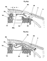
- the housing 2 may be formed from a pair of casing halves 2a and 2b. As illustrated in Figures 9(a) and (b) , an inner wall 50 of the casing halves 2a and 2b cooperates with the airway plate 34 so as to form a second flow path to the mouthpiece 6 which bypasses the pocket (s). Alternatively, an additional component may be provided, to define the second flow path.
- the corresponding inlet 42 of the airway plate 34 is positioned adjacent a periphery of the pocket.
- the corresponding outlet 44 is provided on an opposite side of the pocket such that the airstream between the inlet 42 and outlet 44 crosses the pocket and, hence, picks up any powder from the pocket.
- the inlet 42 is formed as a portion which is directed down into the insert 26 forming the pocket.
- the airstream drawn through the inlet 42 will be directed down into any powder in the insert 26 so as to dislodge it and move it into the airstream so as to be carried out of the outlet 44.
- the recessed channel 46 which connects the volume of the pocket to the outlet 44, is positioned adjacent the inlet 42. In this way, the airstream from the inlet 42 is deflected from the base of the insert 26 (and any powder there) so as to travel back towards the recessed channel 46. Powder carried in the airstream up into the recessed channel 46 is subjected to a relatively sharp change in direction. As a result of this, powder in the airstream tends to be deaggregated. Furthermore, the powder will tend to hit the surfaces of the recessed channel 46 also contributing to deaggregation.
- the shape of the airway path is chosen to force large aggregates of powder to impact the walls as the airflow is forced to change direction, thereby deaggregating large clumps of powder.
- the shape is also designed to ensure that airflow over any surface within the airway is maintained at a high value to avoid excessive powder adhering to the surface.
- corners are rounded and the cross section at each position along the tube is designed to maintain air velocity without generating excessive pressure drop.
- the airflow through the pocket has its minimum area at the inlet to the pocket defined by the dimension "a” whereas the airflow that bypasses the pocket has its minimum cross section just before the airflow join and so is defined by the dimension A.
- the air velocity is highest where the cross sectional area is smallest so this arrangement provides high velocity air to extract the powder from the pocket and uses the high velocity of the bypass air joining the powder contained in the pocket airflow to assist de-aggregation and to protect the walls from powder deposition.
- the airflow velocity through the pocket is controlled mainly by the suction pressure created as the user inhales, whereas the volume flow rate is a factor of both velocity and area.
- a sufficiently high air velocity should be generated to ensure that the powder is entrained in the airflow.
- the velocity-and flow volume are too high then there is the possibility that the whole of the mass of powder in the pocket is pushed through the airway as an agglomerated clump. If this happens, the clump may not accelerate to a sufficient velocity for its impact with the walls in the airway to break it up and provide de-aggregation.
- the powder is removed gradually from the pocket by the airflow.
- a small gap 46a is provided between the surface of the powder in the pocket and the airway roof formed from the division in the airway plate 34 between the inlet 42 and recessed channel 46. This, combined with a dimension for "a" that limits the flow volume through the pocket, ensures that the powder is eroded from the pocket rather than pushed out.
- the inlet hole diameter "a" is chosen to be between 0.5 mm and 2.0 mm for pockets of around 2.0 mm width (in a circumferential direction) and of around 7.3 mm length (in a radial direction). The value chosen depends on the properties of the powder.
- the powder can be removed from the pocket over a time period ranging from between 0.1 s to 1.0 s. This is within the period of the high flow rate of the inhalation cycle and provides good de-aggregation of the powder.
- the arrangement of the inlet hole 42 and channel 46 is particularly advantageous in conjunction with deep narrow pockets of powder.
- a particular flow rate for instance 10 ltr/min
- the surface of the powder will be eroded by a certain depth.
- Increasing the flow rate to, for instance 20 ltr/min, will result in the powder being eroded by a further depth. Since inhalation by users results in flow rates which increase progressively to a maximum, powder is eroded depth by depth and the pocket is emptied gradually over an appropriate period.
- a second flow path is formed between an inner wall 50 of the housing 2 and the outside of the airway plate 34.
- the second flow path bypasses the pocket and increases the overall cross sectional area available through which to inhale.
- a typical flow resistance for the device would be between 2 kPa and 5 Kpa for a flow volume of 60 1/min. Higher flow resistances are chosen for powders which are harder to deaggregate, whereas lower flow resistances are preferred for devices used by children.
- the recessed channel 46 and outlet 44 generally have larger cross sectional areas than the inlet 42. It is envisaged that the minimum cross sectional area for the pocket path would be 3.5 mm 2 to 4.0 mm 2 and for the bypass 5.0 mm 2 to 6.0 mm 2 .
- a patient inhales through both second flow paths whilst drawing powder from the first flow path in use.
- Each of the second flow paths is expected to carry approximately 40% of the total inhaled air for an average use.
- the portion forming the inlet to the pocket can be small and, for a child or patient with COPD (Chronic Obstructive Pulmonary Disease), the total pressure drop should be low.
- COPD Chironic Obstructive Pulmonary Disease
- an inlet portion could be provided with a cross-sectional area of 2 mm 2 and a bypass second flow path with a minimum cross-sectional area of 8 mm 2 , resulting in a ratio of 25%.
- the inlet portion could be provided with a cross-sectional area of 4 mm 2 together with a bypass second flow path having a minimum cross-sectional area of 6 mm 2 , resulting in a ratio of 66%.
- a preferred arrangement has an inlet portion of approximately 3 mm 2 with a second flow path minimum cross- sectional area of 6 mm 2 , resulting in a ratio of 50%.
- the walls of the outlet 44 are orientated so as to direct the flow of air and powder into the second flow path at an angle ⁇ relative to the flow in the second flow path.
- the angle ⁇ is less than 45°, it is possible to substantially reduce the amount of powder which might impact with or stick to the wall 50 opposite the outlet 44.
- the angle ⁇ is no greater than 45°, more preferably no greater than 30°. In this way, substantially no powder will adhere to the wall 50 forming the second flow path to the mouthpiece 6.
- no more than 25%, preferably no more than 15% of a dose remains deposited on the wall 50. In this respect, it will be appreciated that the flow from the bypass past wall 50 will act to scour or scavenge powder from the wall 50.
- the anvil plate 32 and airway plate 34 together form a support for a corresponding carrier 12.
- a support 30 and its corresponding carrier 12 is moved to consecutive-positions to dispense powder from consecutive pockets.
- each pocket has its own first flow path as formed in the airway plate 34. From the description above, it will be appreciated that turbulent flow in removing powder from the pocket and deaggregation of powder occurs within the first flow path. Thus, should any powder adhere to walls within the airway plate 34, this powder is not available for inhalation when subsequent pockets of powder are dispensed.
- the device is preferably arranged such that an inlet passage that provides the air for the flow through the pocket and through the bypass is arranged so that it feeds the air only to the pocket positioned for dispensing, such as illustrated in Figures 9(a) and (b) .
- the indexing of the carrier 12, anvil plate 32 and airway plate 34 after use repositions the inlet 42 and outlet 44 for a used pocket outside of the airflow for the pocket currently in use.
- This arrangement ensures that, even if none of the powder from a pocket is removed after it has been opened, once it has been indexed on, then the powder will be permanently retained within the device such that it will not be inhaled along with a subsequent dose.
- the supports 30 and associated carriers 12 may be rotatably mounted within the housing 2 by means of a chassis sub-assembly 58 as illustrated in Figure 10 .
- the chassis sub-assembly 58 is positioned between the second side surfaces 18 of the carriers 12. It extends axially along the axis of the carriers 12 and is fixed to one or both of the two halves 2a, 2b of the housing 2.
- the priming lever 8 forms part of (or could be attached to) a priming member 60.
- the priming member 60 has a central pivot opening 62 by which it is rotatably supported on a pivot shaft 64 of a chassis 66.
- the priming member 60 and chassis 66 are together positioned between the two carriers 12 and associated supports 30. Furthermore, the chassis 66 is mounted to the housing 2 so as to be rotatably fixed.
- the pivot shaft 64 may itself be located on a shaft 68 provided on the inside of one or both halves 2a, 2b of the housing 2.
- a radial extension 70 (shown in Figure 10 ) may be provided on the chassis 66 to interact with an inner portion of the housing 2 so as to rotationally fix the chassis 66.
- the carriers 12 and associated supports 30 may be rotationally mounted on the chassis 66.
- the priming member 60 includes an elongate cam member 72 which extends in a circumferential direction and has a cam surface 74 on each of two opposites sides.
- Each cam surface 74 interacts with a respective member 76 which will be described as a prodger.
- the priming lever 8 When the priming lever 8 is moved from its first position to its second position, the priming member 60 is rotated relative to the chassis 66, the carriers 12 and their supports 30 such that, in the schematic illustration Figure 11 , the cam member 72 moves upwardly.
- the priming member 60 includes elongate openings either side of the cam member 72 through which arms 80 of the prodgers 76 can extend.
- the chassis 66 holds the prodger 76 rotationally but allows them to move in an axial direction of the device, in other words towards and away from the carriers 12 on either side. Indeed, as illustrated, an aperture 82 exists in the chassis 66 allowing one of the prodgers 76 to extend through the chassis 66 towards a corresponding carrier 12.
- the cam surface 74 on either side of the cam member 72 is such that, as the priming member 60 rotates and the cam member 72 moves upwardly as illustrated in Figure 11 , the prodgers 76 are moved outwardly towards their respective carriers 12.
- Figure 11 the right hand prodger 76 is illustrated in alignment with a pocket in its corresponding carrier 12.
- the priming member 60 rotates and the cam member 72 moves upwardly in Figure 11
- the right hand prodger 76 will be moved outwardly towards its corresponding carrier 12, will penetrate the through hole 20 and push the insert 26a out of the first side surface 16.
- Figure 11 illustrates one insert 26b which has already been pushed out by the prodger 76.
- An indexing mechanism rotates the right hand carrier 12 and its corresponding support 30 to the next position in which the prodger 76 is aligned with a new, unopened pocket. The operation of opening a pocket can then be repeated.
- carriers 12 on either side of the priming member 60 could have respective pockets aligned with the prodgers 76 such that operation of the cam member 72 simultaneously opens pockets of the respective carriers 12.
- the indexing mechanism arranges for one of the prodgers 76 to be aligned with a pocket whilst the other of the prodgers 76 is at a position between pockets. In this way, the dispensing mechanism formed from the cam member 72 and prodgers 76 only opens one pocket at a time.
- the preferred carrier 12 has an array of through holes 20 which includes a space 82 in which a through hole 20 is not formed.
- the cam surfaces 74 are provided with one or more grooves or channels 84. Any excess powder can thus fall into the grooves 84 such that contact and movement between the cam surface 74 and the prodger 76 is not impeded.
- the cam member 72 has itself a limited amount of flexibility. As illustrated, the cam member 72 is provided as an elongate member which is attached to the rest of the priming member 60 at each end with an elongate opening either side of it. This will allow sufficient flexibility for the cam member 72 to move towards and away from the carriers 12.
- cam member 72 is made to a form that varies its force versus distance profile along its length.
- FIG. 12 An example of a suitable form is shown in Figure 12 .
- the preferred embodiment includes two such members arranged back to back.
- the solid wedge shape profile at the right hand side as illustrated in Figure 12 has the same profile as shown in Figure 11 .
- This form rigidly transmits the force applied by the priming lever 8 to the insert 26.
- the length of this profile is chosen so that, for all devices, the prodgers 76 will be moved sufficiently far to break the foils 22, 24 by this profile. Once the foils 22, 24 are broken, much less force is required, but the distance that the insert 26 must move may vary from device to device.
- the cam member 72 cross-section is designed to provide compliance in its movement.
- the cam member 72 provides sufficient force for the insert 26 to be pushed to the end of its available travel in the anvil plate 32.
- the force that the cam member 72 applies to the prodger 76 is limited to that generated as it deforms. This can be much less than the force that would be applied if the prodger 76 were rigidly connected to the priming member 60.
- cam member 72 and prodger 76 The action of cam member 72 and prodger 76 is further illustrated in Figures 16(a) to 16(h) . These Figures show the cam member 72 and prodger 76 at sequential positions, as the priming lever 8 and priming member 60 are moved to open a pocket. The Figures are grouped in pairs, each group giving two views of the same position.
- FIGs 16(a) and 16(b) show the prodger 76a in its fully retracted position at one end of the cam member 72.
- the prodgers 76a and 76b are identical components that clip together with the cam member 72 between them.
- Each prodger 76 has features 86 at the ends of their arms 80 that locate with additional cam surfaces 88 formed on the priming member 60 either side of the elongate openings though which the arms 80 extend.
- a spring could be used to achieve this if it were positioned to press the prodger member 76 against its base surface. However, it is preferable to have an active method for retracting the prodger member 76 that acts as the cam member 72 is returned to the original position. However, where the action of returning the cam member 72 to its original position is also used to index the carrier disc, it is important to ensure that the retraction of the prodger members 76 is completed before the carrier disc is indexed.
- a preferred method of achieving this is by the use of the further cam surfaces 88 located in the non-moving housing in which the cam member and carrier discs are located.
- Figure 17 (a) shows a schematic cross section through the prodgers 76a and 76b also in their retracted position.
- prodger 76a is constrained by the surface 90 of the cam 88 and the cam surface 74 of the cam member 72.
- the cams 88 and cam member 72 are designed so that their thickness C1 and C2 change along the direction of the primary member 60 motion.
- Figure 17 (b) shows the prodgers 76a and 76b in their open position where it can be seen that C2 has increased and C1 decreased compared to their values at the closed position.
- the cam member 72 has a rectangular cross section C2 at one end that gradually increases in area. At the point that it starts to become a compliant wedge, rather than a rigid one, the wedge splits into a central part that pushes up 74 and two side parts that push down 74a.
- This arrangement provides a positive force to both open and close the prodgers 76a and 76b.
- Figures 16(c) to 16(h) show how the concept illustrated in Figures 17(a) and (b) might be implemented.
- Figures 16(c) and (d) show the prodgers 76a and 76b where the cam member 72 has completed approximately one third of its mil travel.
- the cam member 72 over this section is of uniform thickness such that the prodgers are fully retracted. This allows the movement of the rotary priming member 60 on the return stroke over this section to drive the indexing mechanism (as will be described below).
- Figures 16(e) and (f) show the prodgers 76a and 76b where the cam member 72 has completed two thirds of its travel.
- the cam member 72 along this section includes the circumferential grooves 84 mentioned above.
- the raised parts of the cam member 72 are sufficient to rigidly couple the force applied to the priming lever 8 to the prodgers 76a and 76b and the grooves 84 are provided solely to increase the tolerance of the mechanism to stray powder that may have collected on the cam surface 74.
- Figures 16(g) and (h) show the prodger where the cam member 72 has completed its travel.
- the cam member 72 is not solid but split into a central section and two side sections arranged so that the central section presses up against one prodger whilst the two outer sections press down against the other prodger.
- the indexing of the two carrier assemblies is accomplished by an indexing mechanism that causes a carrier 12 to be incremented by one pocket each time the priming lever 8 is actuated and a changeover mechanism that causes the indexing mechanism initially to drive the first carrier 12 but, when the last pocket of that carrier 12 has been used, for that carrier 12 to remain stationery whilst the second carrier 12 is incremented when the indexing mechanism is actuated.
- the preferred indexing mechanism illustrated in Figures 14(a) to (f) uses a 3 peg Geneva 100 that rotates exactly 120° each time the indexing mechanism is actuated.
- the Geneva peg wheel 100 has two gears co-axial with the peg-wheel arranged so that the gears can engage with teeth 35 on the airway plates 34.
- the indexing mechanism drives the first carrier 12 via the Geneva 100 and its gears until it reaches the end of the gear teeth 35 for that carrier 12.
- the next indexing moves the first carrier 12 to its non-driven position, i. e. where the gear teeth 35 are missing, and engages a changeover mechanism which rotates the second carrier 12 until its gears 35 are engaged with the gears on the Geneva peg wheel 100.
- FIG. 14(a) to 14(f) A preferred embodiment of the indexing mechanism is illustrated in Figures 14(a) to 14(f) .
- the peg wheel 100 is located with its axis parallel to the axis of the dose carriers 12 and rotary priming member 60.
- the rotary priming member 60 incorporates many of the functional elements described previously within a single moulded component. It includes the priming lever 8, the cam member 72 and the prodger closing cams 83, as well as being the driving member for the indexing Geneva 100.
- the Figures start with the priming member 60 at the end of its travel where a pocket has been opened and shows what happens as the priming lever 8 is returned to its start position by the closing of the mouthpiece cover 4.
- the peg wheel 100 has six pegs 102a-102c, 103a-103c arranged at 60° intervals around its edge. Three of these pegs 102a, 102b, 102c are longer than the other three 103a, 103b, 103c and are shown with black ends for clarity.
- the leading part 101 of a driving member 104 formed by the priming member 60 passes over the short peg 103a with its periphery touching the edges of the longer pegs 102a and 102c preventing the peg wheel 100 from rotating.
- a ratchet 105 which slopes downward and forward from the driving member 104, engages with the peg 103a.
- the priming member 60 and the driving member 104 continue to move from the position of Figure 14(b) to that of Figure 14(c) , the peg wheel is driven around.
- a slot 106 is cut into the driving member 104 of the priming member 60 into which the long peg 102c can enter.
- the ratchet 105 is starting to disengage with the peg 103a but the trailing edge 107 of the slot 106 now engages with the long peg 102c and continues to drive the peg-wheel 100 around through to the position shown in Figure 14(d) .
- the edge 108 of the driving member 104 passes over the short peg 103c.
- the peg wheel 100 then continues to rotate to the position of Figure 14(e) to complete the forward motion of the peg wheel 100.
- the slot 109 is provided to accommodate the long peg 102b. At this position the dose carrier 12 has been driven so that the next pocket to be opened is beyond its desired location and the mouthpiece cover 4 that has been driving the rotary priming member 60 is fully closed.
- Figure 14(f) shows the gears 35 on one of the airway plates 34 engaged with the gear on the peg wheel 100.
- the number of gear teeth on the airway plates 34 and peg wheel 100 are arranged so that the 120° motion of the peg wheel increments the dose carrier plate exactly one pocket pitch.
- the arrangement described here is advantageous in achieving precise intermittent motion control of two disks within very tight space allocation and with a minimal number of components.
- a changeover mechanism is preferably provided to cause the indexing mechanism initially to drive a first disk and, when this has had all of its pockets opened, to then drive a second disk.
- Such a changeover mechanism will be described with reference to Figure 15(a) to Figure 15(e) .
- Figures show the device viewed edge on with the two airway plates 34 arranged horizontally.
- Figure 15(a) shows the device in its position before a first pocket is opened.
- airway plate 34a has been indexed by one position to the right.
- the two features 123 on the periphery of the airway plate 34a can be seen to have shifted.
- Figure 15(c) shows the position after the last pocket of the lower carrier 12 of airway plate 34a has been opened.
- the rotation has brought the features 123 right around the device to the position shown.
- the next indexing operation causes the lower airway plate 34a to move as before.
- the leading feature 123 pushes on a changeover component 124 which pushes on the feature 122 on the upper airway plate 34b causing both plates 34a and 34b and carriers 12 to move together.
- the prodger 76b was aligned to the missing pocket part 82 providing a hard surface against which that prodger 76b could push whilst the other prodger 76a pushed against a pocket of the lower airway plate 34a.
- the indexing operation performed by the changeover component 124 on the upper airway plate 34b moves the gear of the upper airway plate 34b to engage with the gear of the peg wheel 100 and aligns the first pocket of the upper carrier 12 with the prodgers 76.
- indexing by the priming member 60 causes the lower airway plate 34a to continue to move to a position which the gear teeth 35 on the lower airway plate 34a disengage from the gear on the peg wheel 100.
- the priming member 60 and peg wheel 100 move the lower airway plate 34a to a position in which the missing teeth on the gear 35 of the lower airway plate 34a are aligned with the gear on the Geneva peg wheel 100 and the missing pocket segment 82 of the lower dose carrier 12 is aligned with the prodgers 76.
- the clip 125 provides an interlock that prevents any frictional coupling from causing the upper airway plate 34b to move before the lower airway plate 34a has arrived at the correct location.
- the indexing of the device in addition to moving the next pocket into alignment with the prodgers 76, preferably actuates a dose counter that provides a visual indication to the user of the number of doses remaining.
- the operation of the dose indicator will be described with reference to Figures 19 and 20 .
- the device when dispensing medicament, indicates to the user the number of doses remaining in the device.
- a preferred method is to employ a display with separate units and tens indication, driven such that the tens display index one number as the unit display index from 9 to 0. This allows larger numbers to be used within the same casework.
- the two discs may be provided concentrically one within the other and preferably coaxially with the axis of the device, for instance on the shaft 68 illustrated in Figure 13 .
- the displayed units and tens are visible through the window 10 illustrated in Figure 1(a) .
- the display counts down to zero, but the tens disc is not provided with a "0". Instead, it is provided with an indicator, for instance a symbol, colour light etc to indicate to the user that the device is nearing the end of its functional life.
- the preferred embodiment uses another Geneva and gear arrangement that is driven from the movement of the carrier discs. It is preferable that a single counter is increment initially by the motion of the first carrier disc and subsequently by the motion of the second carrier disc such that the fact that the device contains two carrier discs is not apparent to the user.
- Figure 20(a) shows a view of the dose counter display.
- the counter consists of two concentric rings 130, 131with numbers formed in the rings facing toward the outer casing 2 of the device.
- the outer ring is the units counter 130 and the inner ring is the tens counter 131.
- the window 10 is provided in the outer casework 2 is arranged to permit the user to see only one digit of the units counter 130 and the adjacent digit of the tens counter 131.
- the counter indicates that there are 21 doses left.
- the operation of the counter requires the units counter 130 to index by 36° every time the indexing mechanism is actuated and for the tens counter to index by 36° only as the units counter moves from displaying 9 to 0. It can be seen that the units digits are evenly distributed around the ring whereas, for the example shown in Figure 20(a) which has 60 doses, there are only the digits 1 to 6 on the tens counter 131.
- the counter is driven by a gear 133 which itself is driven by one of the gears on the indexing Geneva peg wheel 100.
- the indexing Geneva 100 turns through 120° for each indexing operation and the gear on it has six teeth.
- the gear 133 has fifteen teeth and engages with the twenty teeth 134 of the units counter illustrated in Figure 19(a) .
- the 120° rotation of the indexing Geneva 100 drives the units counter 130 through 36°.
- Figure 19(a) shows the units counter ring 130 viewed from behind the face on which the numbers are formed.
- a counter Geneva wheel 135 is shown located inside-the units counter ring 130 for mounting on a fixed post which is part of chassis 66.
- An actuated peg 136 for the counter Geneva mechanism is located on the inner diameter of the units counter wheel 130. This peg 136 engages with one of the three indentations 137 in the Geneva wheel 135 causing the Geneva wheel 135 to rotate by 120° as the peg 136 passes by the wheel 135 during its 36 rotation between displaying the digits 9 and 0.
- the peg 136 is on the outer larger diameter component 130 and this drives the slotted smaller wheel 135 whereas, for the indexing Geneva 100, the slots are on the larger wheel and they drive the pegs on the smaller wheel.
- both are examples of a Geneva type mechanism providing intermittent rotation with accurate location between the rotations.
- the Geneva wheel includes cam faces 138 which contact against the inner wall 139 of the units counter 130 preventing the Geneva 135 rotating between indexing. To permit the Geneva 135 to rotate as it is pushed by the peg 136, there is a gap 139a in the inner wall 139 adjacent to the peg 136.
- the Geneva has a 3 tooth gear on its underside engaging with pegs on the tens counter ring to drive it.
- Figure 19(a) through to Figure 19(e) show the positions of the Geneva wheel 135, the drive gear 133 and the units counter 130 at four stages during the 36° rotation of the units counter.
- Figure 20(a) to Figure 20(c) show the motion of the two counter wheels as they index from 21 doses to 20 doses remaining, when only the outer units counter 130 moves.
- Figure 20(c) to Figure 20(e) show the corresponding situation from 20 to 19 doses remaining where both counters index.
- the remaining doses display will read 0 indicating that the device is empty to the user.
- the device provides some positive feedback to the user, as it is being actuated, that it is empty.
- This feedback can be in the form that the priming lever 8 cannot be moved to its operating position with the level of force normally used.
- This tactile feedback provides a lockout feature.
- a preferred method of achieving this with the two disc device is to arrange that after the last dose has been used, the second disc indexes such that it has no pocket under the prodger. At this point, the two prodger members 76 both face surfaces of the discs without pockets. Thus as the priming lever 8 is moved, neither prodger member 76 can move onto a disc and the resulting force on the prodger members 76 is transmitted back through the drive mechanism to the priming lever 8 and hence to the user.
- this mechanism provides a clear visual indication of the number of doses remaining with a minimal number of components.
- the preferred embodiment described above is arranged consecutively to dispense the powder from each pocket of one carrier and then subsequently the powder from each pocket of the other carrier.
- a device to dispense powder from pockets alternately from one carrier and then the other carrier.
- pockets of both disks may be dispensed simultaneously.
- a steroid compound could be dispensed from one disk and a long acting beta agonist (LABA) from the other disk for the treatment of, for example, asthma or chronic obstructive pulmonary disease.
- long acting beta agonists include formoterol and salmeterol and examples of steroids include fluticasone propionate, budesonide and monetasone furoate.
- the device can be provided with carriers preinstalled or, alternatively, ready for use with appropriate carriers.
- a first cover sub-assembly A receives one carrier 12 and a second cover sub-assembly B receives another carrier 12.
- the two cover sub-assemblies A and B are then secured to one another with a chassis sub-assembly C therebetween.
- a device for dispensing individual doses of powder from respective pockets of a carrier includes: a support for a carrier having a plurality of pockets containing respective doses of powder; and a mouthpiece through which to inhale an airstream carrying a dose of powder; the device further including: walls for defining individual respective first flow paths downstream of each respective pocket of a supported carrier wherein each individual respective first flow path is defined entirely by respective walls unique to that individual respective first flow path, is for connecting the corresponding respective pocket to the mouthpiece and is for deaggregating powder in the airstream.
- a device for dispensing individual doses of powder from respective pockets of a carrier includes: a support for a carrier having a plurality of pockets containing respective doses of powder; and a mouthpiece through which to inhale an airstream carrying a dose of powder; the device further including: walls for defining individual respective first flow paths downstream of each pocket of a supported carrier for connecting the pockets to the mouthpiece and deaggregating powder in the airstream; and an arrangement for moving individually each pocket from a respective storage position to a respective discharge position, wherein each pocket, in the respective discharge position, forms an integral part of the individual respective first flow path.
- Embodiment 3 A device according to embodiment 2 for use with a carrier having pockets provided with a lidding sheet, the device allowing the lidding sheet to be ruptured as a consequence of moving a pocket from a respective storage position to a respective discharge position.
- Embodiment 4 A device according to embodiment 1, 2 or 3 further including: walls defining a second flow path connecting with the mouthpiece and bypassing the pockets.
- Embodiment 5 A device according to embodiment 4 wherein: with the device configured to dispense a dose of powder from one of the pockets of the supported carrier, the respective first flow path connects with the second flow path downstream of the bypass and at an angle such that substantially no powder impacts with the walls defining the second flow path.
- Embodiment 6 A device according to embodiment 5 wherein: where the respective first flow path connects with the second flow path, the angle between the flow paths is less than 45 degrees and preferably less than 30 degrees.
- Embodiment 7 A device according to embodiment 4, 5 or 6 wherein: the support for a carrier and the walls defining the first flow paths are moveable with a supported carrier so as selectively to connect respective first flow paths with the second flow path and hence selectively dispense doses of powder from respective pockets of the supported carrier.
- Embodiment 8 A device according to any one of embodiments 4 to 7 wherein: the walls defining the first flow paths include, upstream of the pockets, respective portions of relatively reduced cross-sectional area orientated so as to be directed towards respective pockets and direct a relatively high velocity airstream into the respective pockets.
- a device for dispensing a dose of powder from a pocket of a carrier includes: a support for a carrier having a pocket containing a dose of powder; and a mouthpiece through which to inhale an airstream carrying a dose of powder; the device further including: walls defining first and second flow paths communicating with the mouthpiece, the first flow path communicating with the pocket of the supported carrier and the second flow path bypassing the pocket; wherein the walls defining the first flow path include, upstream of the pocket, a portion of relatively reduced cross-sectional area orientated so as to be directed towards the pocket and direct a relatively high velocity airstream into the pocket.
- Embodiment 10 A device according to embodiment 8 or 9 wherein: the portion(s) have a cross-sectional area between 50% and 66% of the cross-sectional area of the smallest part of the second flow path.
- Embodiment 11 A device according to embodiment 8, 9 or 10 wherein: the portion(s) have a cross-sectional area of between 2.0 mm 2 and 10.0 mm 2 .
- a device for dispensing individual doses of powder from respective pockets of a pair of carriers includes: a support for two disc shaped carriers, each disc shaped carrier having at least one substantially planar first side surface having an annular array of cavities in which respective pockets are formed and a respective first lidding sheet sealed to the first side surface for enclosing the cavities, wherein the supports are for rotatably supporting the carriers about a substantially common axis; a mouthpiece through which to inhale an airstream carrying powder from the carriers; a dispensing mechanism for releasing into the airstream the powder of a respective pocket of a supported carrier; and an indexing mechanism for rotating the carriers relative to the dispensing mechanism so as to enable powder to be released from different pockets.
- Embodiment 13 A device according to embodiment 12 wherein: between consecutive dispensing of powder from one of said carriers, the indexing mechanism is operable to rotate both of said carriers relative to the dispensing mechanism.
- Embodiment 14 A device according to embodiment 13 wherein: between consecutive dispensing of powder from the other of said carriers, the indexing mechanism is operable to rotate both of said carriers relative to the dispensing mechanism.
- Embodiment 15 A device according to embodiment 12, 13 or 14 wherein: the dispensing mechanism is operable to release powder from a pocket of each carrier for a single inhalation of both respective powders simultaneously.
- Embodiment 16 A device according to embodiment 15 wherein: the dispensing mechanism is operable to release powder from a pocket of each carrier simultaneously.
- Embodiment 17 A device according to embodiment 12, 13 or 14 wherein: the dispensing mechanism is operable to release powder from a pocket of one of the carriers for inhalation then to release powder from the other of the carriers for inhalation.
- Embodiment 18 A device according to embodiment 15, 16 or 17 wherein: the dispensing mechanism is operable to release powder from a pocket of one carrier and from a pocket of the other carrier consecutively.
- Embodiment 19 A device according to any one of embodiments 12 to 18 including two of said disc shaped carriers respectively containing powder of different medicament.
- Embodiment 20 A device according to embodiment 12 wherein: between consecutive dispensing of powder, the indexing mechanism is operable to rotate one of said carriers in turn between consecutive dispensing positions before rotating the other of said carriers.
- Embodiment 21 A device according to embodiment 12 or 20 wherein: the dispensing mechanism and the indexing mechanism are together operable to dispense the powder from all of the pockets from one of said carriers before dispensing powder from pockets of the other of said carriers.
- a device for dispensing individual doses of powder from respective packets of a carrier includes: a first support for a first carrier having first and second side surfaces opposite each other, an array of cavities in which respective pockets are formed and a first lidding sheet sealed to the first side surface; a first prodger member moveable towards and away from the second side surface of a supported first carrier between a retracted and an extended position; a cam member adjacent to and moveable generally parallel with the second side surface of a supported carrier between a rest position and a primed position; wherein the cam member has a first cam surface for engaging with the first prodger member such that movement of the cam member from the rest position to the primed position moves the prodger member from the retracted position to the extended position so as to press on the second side surface of a supported first carrier and outwardly rupture the first lidding sheet of the supported first carrier.
- a device further including: a second support for a second carrier having first and second side surfaces opposite each other, an array of cavities in which respective pockets are formed and a first lidding sheet sealed to the first side surface, the first and second carriers being supported with respective second side surfaces facing each other; a second prodger member moveable towards and away from the second side surface of a supported second carrier between a retracted and an extended position; wherein the cam member has a second cam surface for engaging with the second prodger member such that movement of the cam member from the rest position to the primed position moves the second prodger member from the retracted position to the extended position so as to press upon the second side surface of a supported second carrier and outwardly rupture the first lidding sheet of the supported second carrier.
- Embodiment 24 A device according to embodiment 23 further including: an indexing mechanism for moving the first and second supports relative to the first and second prodger members so as to selectively align pockets of the carriers with respective prodger members.
- Embodiment 25 A device according to embodiment 24 wherein: the indexing mechanism is arranged such that, with one of the first and second prodger members aligned with a respective pocket, the other of the first and second prodger members is aligned between respective pockets whereby movement of the cam member from the rest position to the primed position causes only the one of the first and second prodger members to outwardly rupture the first lidding sheet of the corresponding one of the first and second carriers.
- Embodiment 26 A device according to embodiment 25 wherein: cam member is moveable in a direction towards and away from the second side surfaces of supported first and second carriers such that, when the other of the first and second prodger members is aligned between respective pockets, movement of the cam member from the rest position to the primed position and the resulting engagement of the other of the first and second prodger members with the corresponding cam surfaces, causes the other of the first and second prodger members to abut the corresponding second side surface and the cam member to be moved towards the corresponding one of the first and second carriers.
- Embodiment 27 A device according to embodiment 24, 25 or 26 wherein: the cam member is provided on a priming member moveable as part of the indexing mechanism.
- Embodiment 28 A device according to any one of embodiments 24 to 27 wherein: the indexing mechanism is arranged such that, after the first and second carriers have been indexed past all of their respective pockets, the first and second prodger members are both aligned between pockets of respective carriers and, hence, provide resistance to movement of the cam member.
- Embodiment 29 A device according to any one of embodiments 23 to 28 wherein: the cam member includes an elongate flexible member having the first and second cam surfaces on opposite sides.
- Embodiment 30 A device according to any one of embodiments 22 to 29 wherein: the first cam surface and/or the second cam surface include at least one groove into which any stray powder from previously dispensed pockets may move.
- Embodiment 31 A device according to any one of embodiments 22 to 30 for use with carriers having said cavities formed from respective through holes between the first and second side surfaces, having second lidding sheets sealed to the second side surfaces and having a respective cup-shaped insert in each cavity orientated with an open portion facing the respective first lidding sheet, wherein: the first prodger member and/or second prodger member is arranged to penetrate an aligned through-hole through a second lidding sheet so as to push the corresponding insert outwardly through the first lidding sheet.
- Embodiment 32 A device according to any one of embodiments 22 to 31 wherein: at least one of the cam surfaces is resiliently deformable, the cam member being dimensioned so as to move the prodger members beyond the extended position such that, once a prodger member reaches its respective extended position, further movement of the cam member causes the at least one of the cam surfaces to resiliently deform.
- a device for dispensing individual doses of powder from respective pockets of a carrier includes: a chassis; a first support mounted on the chassis for rotation about a central axis and for supporting a first carrier having cavities with respective pockets formed therein and arranged in a circular array centred on the central axis, the first support including an array of gear teeth centred on the central axis; a priming member mounted on the chassis for rotation about the central axis; and an intermittent-motion mounted on the chassis for interaction with the priming member and gear teeth of the first support such that rotation of the priming member from a first position to a second position causes rotation of the first support by a predetermined angle and rotation of the priming member back from the second position to the first position causes no rotation of the first support.
- Embodiment 34 A device according to embodiment 33, wherein the intermittent-motion mechanism is a Geneva wheel rotatably mounted on the chassis on an axis offset from the central axis.
- the intermittent-motion mechanism is a Geneva wheel rotatably mounted on the chassis on an axis offset from the central axis.
- Embodiment 35 A device according to embodiment 34 further including: a second support mounted on the chassis for rotation about the central axis and for supporting a second carrier having cavities with respective pockets formed therein and arranged in a circular array centred on the central axis, the second support including an array of gear teeth centred on the central axis; wherein the Geneva wheel may interact with the gear teeth of the second support such that rotation of the priming member from the first position to the second position causes rotation of the second support by a predetermined angle and rotation of the priming member back from the second position to the first position causes no rotation of the second support.
- Embodiment 36 A device according to embodiment 35 wherein: the respective arrays of gear teeth of the first and second supports are incomplete circular arrays leaving respective spaces such that, with a space positioned adjacent the Geneva wheel, rotation of the priming member will not rotate the respective supports.
- Embodiment 37 A device according to embodiment 36 further including: a changeover component located between the first and second supports, the first support having a first feature engaging with the changeover component and the second support having a second feature for engaging with the changeover component; wherein with the space of the second support adjacent the Geneva wheel, consecutive rotations of the priming member cause only the first support to rotate until the first feature engages the changeover component and then to move the changeover component so as to engage with the second feature and rotate the second support to a position with the space of the second support not adjacent the Geneva wheel, the space of the first support then being adjacent the Geneva wheel and consecutive rotations of the priming member causing only the second support to rotate.
- Embodiment 38 A device according to embodiment 37 wherein: the changeover component is arranged such that, when the priming member rotates the second support back around to the position with the space of the second support adjacent the Geneva wheel, the second feature does not engage with the changeover component and consecutive rotations of the priming member cause no rotation of either support.
- a device for dispensing individual doses of powder from respective pockets of a carrier includes: first and second supports rotatable about a central axis and for supporting respective first and second carriers having cavities with respective pockets formed therein and arranged in respective first and second circular arrays centred on the central axis; a changeover component located between the first and second supports, the first support having a first feature for engaging with the changeover component and the second support having a second feature for engaging with the changeover component; and an indexing mechanism arranged to rotate each of the first and second supports; wherein the indexing mechanism is arranged to rotate the first support until the first feature engages the changeover component such that the first support then moves the changeover component, the changeover component being arranged to then engage the second feature so as to rotate the second support to a position from which the indexing mechanism is arranged to rotate the second support.
- Embodiment 40 A device according to embodiment 39 wherein: the changeover component rotates the second support from a position at which the indexing mechanism does not rotate the second support and, when the first support moves the changeover component, the first support moves to a position in which the indexing mechanism does not rotate the first support.
- Embodiment 41 A device according to embodiment 40 wherein: when the second support is rotated back around to the position at which the indexing mechanism does not rotate the second support, consecutive operations of the indexing mechanism cause no rotation of either component.
- Embodiment 42 A device according to any one of embodiments 37 to 41 wherein: the changeover component is supported freely between and by the first and second supports.
- Embodiment 43 A device according to any one of embodiments 12 to 32 and 39 to 42 wherein: each support includes a peripheral array of gear teeth; and the indexing mechanism is engageable with the gear teeth so as selectively to move the supports and carriers.
- Embodiment 44 A device according to embodiment 43 wherein the indexing mechanism includes: an priming member mounted for rotation about a central axis; and an intermittent-motion mechanism, preferably a Geneva wheel rotatably mounted on an axis offset from the central axis, for interaction with the priming member and gear teeth of the supports such that rotation of the priming member from a first position to a second position causes rotation of at least one of the supports by a predetermined angle and rotation of the priming member back from the second position causes no rotation of the at least one of the supports.
- an intermittent-motion mechanism preferably a Geneva wheel rotatably mounted on an axis offset from the central axis
- Embodiment 45 A device according to any one of embodiments 22 to 44 further including a dose counter having: a first counter ring having an indication of unit counts on a first display surface, the first counter ring being rotatable about a counter axis; a second counter ring having an indication of tens counts on a second display surface, the second counter ring being rotatable about the counter axis; and an intermittent-motion mechanism, preferably a Geneva mechanism, for driving the second counter ring from the first counter ring and rotating the second counter ring between consecutive tens counts when the first counter ring rotates between two predetermined consecutive unit counts.
- a dose counter having: a first counter ring having an indication of unit counts on a first display surface, the first counter ring being rotatable about a counter axis; a second counter ring having an indication of tens counts on a second display surface, the second counter ring being rotatable about the counter axis; and an intermittent-motion mechanism, preferably a Geneva mechanism, for
- Embodiment 46 A device according to embodiment 45 wherein the first counter ring is driven with rotation of the first support.
- Embodiment 47 A device according to embodiment 45 or 46 wherein the counter axis is coaxial with the first support.
- a device for dispensing individual doses of powder from respective pockets of a carrier includes: an indexing mechanism for indexing the carrier between respective pockets; a first counter ring having an indication of unit counts on a first display surface, the first counter ring being rotatable about a counter axis; a second counter ring having an indication of tens counts on a second display surface, the second counter ring being rotatable about the counter axis; and an intermittent-motion mechanism for driving the second counter ring from the first counter ring and rotating the second counter ring between consecutive tens counts when the first counter ring rotates between two predetermined consecutive unit counts, the first counter ring being driven with the indexing mechanism.
- Embodiment 49 A device according to embodiment 48 wherein the intermittent-motion mechanism is a Geneva mechanism.
- Embodiment 50 A device according to embodiment 49 wherein: the second counter ring is positioned within the first counter ring, the first counter ring includes a pin for engaging a Geneva wheel rotatable about an axis offset from the counter axis and the second counter ring includes features engageable by the Geneva wheel.
- Embodiment 51 A device according to any one of embodiments 45 to 50 wherein: the first and second counter rings are positioned one within the other, with the first and second display surfaces adjacent each other.
- a device for dispensing individual doses of powder from respective pockets of a carrier includes: an indexing mechanism for indexing the carrier between respective pockets; a first counter ring having an indication of unit counts on a first display surface, the first counter ring being rotatable about a counter axis; a second counter ring having an indication of tens counts on a second display surface, the second counter ring being rotatable about the counter axis; and a mechanism for rotating the second counter ring between consecutive tens counts when the first counter ring rotates between two predetermined consecutive unit counts, the first counter ring being driven with the indexing mechanism; wherein the first and second counter rings are positioned one with the other, with the first and second display surfaces adjacent each other.
- Embodiment 53 A device according to any preceding embodiment housing at least one carrier.
Priority Applications (7)
| Application Number | Priority Date | Filing Date | Title |
|---|---|---|---|
| EP21152808.8A EP3842090B1 (de) | 2003-07-02 | 2004-06-25 | Spendervorrichtung |
| SI200432459T SI2752216T1 (sl) | 2003-07-02 | 2004-06-25 | Dajalna naprava |
| DK18204617.7T DK3459578T3 (da) | 2003-07-02 | 2004-06-25 | Dispenseringsindretning |
| PL18204617T PL3459578T3 (pl) | 2003-07-02 | 2004-06-25 | Urządzenie dozujące |
| PL14162934T PL2752216T3 (pl) | 2003-07-02 | 2004-06-25 | Urządzenie dozujące |
| EP18204617.7A EP3459578B1 (de) | 2003-07-02 | 2004-06-25 | Spendervorrichtung |
| CY20211100362T CY1124060T1 (el) | 2003-07-02 | 2021-04-27 | Συσκευη χορηγησης |
Applications Claiming Priority (3)
| Application Number | Priority Date | Filing Date | Title |
|---|---|---|---|
| GBGB0315509.0A GB0315509D0 (en) | 2003-07-02 | 2003-07-02 | Dispensing device |
| EP04743099.6A EP1644063B1 (de) | 2003-07-02 | 2004-06-25 | Abgabevorrichtung |
| PCT/GB2004/002748 WO2005002654A2 (en) | 2003-07-02 | 2004-06-25 | Dispensing device |
Related Parent Applications (2)
| Application Number | Title | Priority Date | Filing Date |
|---|---|---|---|
| EP04743099.6A Division-Into EP1644063B1 (de) | 2003-07-02 | 2004-06-25 | Abgabevorrichtung |
| EP04743099.6A Division EP1644063B1 (de) | 2003-07-02 | 2004-06-25 | Abgabevorrichtung |
Related Child Applications (2)
| Application Number | Title | Priority Date | Filing Date |
|---|---|---|---|
| EP21152808.8A Division EP3842090B1 (de) | 2003-07-02 | 2004-06-25 | Spendervorrichtung |
| EP18204617.7A Division EP3459578B1 (de) | 2003-07-02 | 2004-06-25 | Spendervorrichtung |
Publications (2)
| Publication Number | Publication Date |
|---|---|
| EP2752216A1 true EP2752216A1 (de) | 2014-07-09 |
| EP2752216B1 EP2752216B1 (de) | 2018-11-07 |
Family
ID=27676542
Family Applications (8)
| Application Number | Title | Priority Date | Filing Date |
|---|---|---|---|
| EP21152808.8A Active EP3842090B1 (de) | 2003-07-02 | 2004-06-25 | Spendervorrichtung |
| EP04743099.6A Active EP1644063B1 (de) | 2003-07-02 | 2004-06-25 | Abgabevorrichtung |
| EP14162917.0A Active EP2752214B1 (de) | 2003-07-02 | 2004-06-25 | Spendervorrichtung |
| EP14162911.3A Active EP2752212B1 (de) | 2003-07-02 | 2004-06-25 | Spendervorrichtung |
| EP14162934.5A Active EP2752216B1 (de) | 2003-07-02 | 2004-06-25 | Spendervorrichtung |
| EP14162924.6A Active EP2752215B1 (de) | 2003-07-02 | 2004-06-25 | Spendervorrichtung |
| EP18204617.7A Active EP3459578B1 (de) | 2003-07-02 | 2004-06-25 | Spendervorrichtung |
| EP14162913.9A Active EP2752213B1 (de) | 2003-07-02 | 2004-06-25 | Spendervorrichtung |
Family Applications Before (4)
| Application Number | Title | Priority Date | Filing Date |
|---|---|---|---|
| EP21152808.8A Active EP3842090B1 (de) | 2003-07-02 | 2004-06-25 | Spendervorrichtung |
| EP04743099.6A Active EP1644063B1 (de) | 2003-07-02 | 2004-06-25 | Abgabevorrichtung |
| EP14162917.0A Active EP2752214B1 (de) | 2003-07-02 | 2004-06-25 | Spendervorrichtung |
| EP14162911.3A Active EP2752212B1 (de) | 2003-07-02 | 2004-06-25 | Spendervorrichtung |
Family Applications After (3)
| Application Number | Title | Priority Date | Filing Date |
|---|---|---|---|
| EP14162924.6A Active EP2752215B1 (de) | 2003-07-02 | 2004-06-25 | Spendervorrichtung |
| EP18204617.7A Active EP3459578B1 (de) | 2003-07-02 | 2004-06-25 | Spendervorrichtung |
| EP14162913.9A Active EP2752213B1 (de) | 2003-07-02 | 2004-06-25 | Spendervorrichtung |
Country Status (27)
| Country | Link |
|---|---|
| US (7) | US8181645B2 (de) |
| EP (8) | EP3842090B1 (de) |
| JP (6) | JP4776534B2 (de) |
| KR (3) | KR20070072633A (de) |
| CN (2) | CN101518663B (de) |
| AU (2) | AU2004253333B2 (de) |
| BR (4) | BR122015016057B8 (de) |
| CA (6) | CA2531483C (de) |
| CY (7) | CY1119680T1 (de) |
| DK (8) | DK2752216T3 (de) |
| ES (7) | ES2708931T3 (de) |
| FI (1) | FI3842090T3 (de) |
| GB (1) | GB0315509D0 (de) |
| HK (2) | HK1134049A1 (de) |
| HU (7) | HUE054265T2 (de) |
| IL (2) | IL172474A0 (de) |
| MX (2) | MXPA06000175A (de) |
| NO (2) | NO337015B1 (de) |
| NZ (2) | NZ572253A (de) |
| PH (1) | PH12013501053B1 (de) |
| PL (7) | PL3459578T3 (de) |
| PT (8) | PT2752216T (de) |
| RU (2) | RU2322271C2 (de) |
| SI (7) | SI2752216T1 (de) |
| TR (2) | TR201802960T4 (de) |
| TW (1) | TWI291878B (de) |
| WO (1) | WO2005002654A2 (de) |
Families Citing this family (157)
| Publication number | Priority date | Publication date | Assignee | Title |
|---|---|---|---|---|
| US9006175B2 (en) | 1999-06-29 | 2015-04-14 | Mannkind Corporation | Potentiation of glucose elimination |
| JP4681231B2 (ja) | 2002-03-20 | 2011-05-11 | マンカインド コーポレイション | 吸入装置 |
| GB0303870D0 (en) * | 2003-02-20 | 2003-03-26 | Norton Healthcare Ltd | Pre-metered dose magazine for breath-actuated dry powder inhaler |
| GB0315509D0 (en) | 2003-07-02 | 2003-08-06 | Meridica Ltd | Dispensing device |
| US7624733B2 (en) | 2004-02-09 | 2009-12-01 | Oriel Therapeutics, Inc. | Inhalers with extendable/retractable forward member and associated methods of dispensing inhalant substances |
| MXPA06009133A (es) | 2004-02-16 | 2007-01-26 | Glaxo Group Ltd | Contador para usarse con un distribuidor de medicamento. |
| US7861712B2 (en) | 2004-04-23 | 2011-01-04 | Manta Product Development | Sealed capsule including an integrated puncturing mechanism |
| EP1786784B1 (de) | 2004-08-20 | 2010-10-27 | MannKind Corporation | Katalyse der diketopiperazinsynthese |
| DK2322180T3 (en) | 2004-08-23 | 2015-06-15 | Mannkind Corp | Diketopiperazinsalte for drug delivery |
| GB0425518D0 (en) | 2004-11-19 | 2004-12-22 | Clinical Designs Ltd | Substance source |
| GB0427856D0 (en) * | 2004-12-20 | 2005-01-19 | Glaxo Group Ltd | Maniflod for use in medicament dispenser |
| GB0427858D0 (en) | 2004-12-20 | 2005-01-19 | Glaxo Group Ltd | Manifold for use in medicament dispenser |
| GB0428204D0 (en) | 2004-12-23 | 2005-01-26 | Clinical Designs Ltd | Medicament container |
| US20090042843A1 (en) * | 2005-05-04 | 2009-02-12 | Boehringer Ingelheim International Gmbh | Inhalation Device Containing Plural Doses of a Pharmaceutical Composition |
| US7614429B2 (en) | 2005-05-18 | 2009-11-10 | Symyx Solutions, Inc. | Apparatus and methods for storing and dispensing solid material |
| US8763605B2 (en) | 2005-07-20 | 2014-07-01 | Manta Devices, Llc | Inhalation device |
| PL1917108T3 (pl) * | 2005-08-24 | 2013-03-29 | Boehringer Ingelheim Int | Rozpylacz zawierający licznik i blokadę końca operacji |
| GB0518400D0 (en) | 2005-09-09 | 2005-10-19 | Clinical Designs Ltd | Dispenser |
| KR101643478B1 (ko) | 2005-09-14 | 2016-07-27 | 맨카인드 코포레이션 | 활성제에 대한 결정질 미립자 표면의 친화력의 증가를 기반으로 하는 약물 제제화의 방법 |
| GB0519151D0 (en) * | 2005-09-20 | 2005-10-26 | Aventis Pharma Ltd | Inhaler |
| DE102005057685A1 (de) * | 2005-12-01 | 2007-06-06 | Boehringer Ingelheim Pharma Gmbh & Co. Kg | Inhalator und Speicher für eine trockene Arzneimittelformulierung sowie diesbezügliche Verfahren und Verwendung |
| EP1795221A1 (de) * | 2005-12-02 | 2007-06-13 | Boehringer Ingelheim Pharma GmbH & Co. KG | Aufbewahrungs- und Abgabevorrichtung, sowie Verfahren zur Abgabe einer Formulierung |
| AR058289A1 (es) * | 2005-12-12 | 2008-01-30 | Glaxo Group Ltd | Colector para ser usado en dispensador de medicamento |
| AR058290A1 (es) * | 2005-12-12 | 2008-01-30 | Glaxo Group Ltd | Dispensador de medicamento |
| GB0602897D0 (en) * | 2006-02-13 | 2006-03-22 | Jagotec Ag | Improvements In Or Relating To Dry Powder Inhaler Devices |
| MX360812B (es) | 2006-02-22 | 2018-11-16 | Mannkind Corp | Un método para mejorar las propiedades farmacéuticas de micropartículas que contienen dicetopiperazina y un agente activo. |
| GB0605150D0 (en) | 2006-03-14 | 2006-04-26 | Glaxo Group Ltd | Counter For Use With A Medicament Dispenser |
| US8037880B2 (en) * | 2006-04-07 | 2011-10-18 | The University Of Western Ontario | Dry powder inhaler |
| EP1844806A1 (de) | 2006-04-13 | 2007-10-17 | Boehringer Ingelheim Pharma GmbH | Medikamenten-Ausgabevorrichtung, Medikamentenmagazin dafür, und Verfahren zur Entnahme eines Medikaments aus einer Medikamentenkammer |
| EP1844809A1 (de) | 2006-04-13 | 2007-10-17 | Boehringer Ingelheim Pharma GmbH & Co. KG | Medikamentenmagazin für einen Inhalator, sowie Mehrdosispulverinhalator |
| WO2007118490A1 (en) * | 2006-04-13 | 2007-10-25 | Boehringer Ingelheim Microparts Gmbh | Dispensing device |
| US7841338B2 (en) | 2006-04-13 | 2010-11-30 | Boehringer Ingelheim International Gmbh | Dispensing device |
| GR1005620B (el) * | 2006-05-09 | 2007-09-03 | Βελτιωση συσκευης εισπνοων ξηρης σκονης | |
| GR1005668B (el) * | 2006-05-09 | 2007-10-02 | Συσκευη εισπνοων ξηρης σκονης για την ταυτοχρονη χορηγηση περισσοτερων απο μιας φαρμακευτικων ουσιων | |
| US9457161B2 (en) | 2006-05-18 | 2016-10-04 | Boehringer Ingelheim International Gmbh | Inhaler |
| DE102006043637A1 (de) | 2006-05-18 | 2007-11-22 | Boehringer Ingelheim Pharma Gmbh & Co. Kg | Zerstäuber |
| DE102006023662A1 (de) * | 2006-05-18 | 2007-11-22 | Boehringer Ingelheim Pharma Gmbh & Co. Kg | Inhalator |
| EP1925295A1 (de) | 2006-11-22 | 2008-05-28 | Boehringer Ingelheim Pharma GmbH & Co. KG | Stabile Pulverformulierung enthaltend ein Anticholinergikum |
| WO2008114034A2 (en) * | 2007-03-21 | 2008-09-25 | Cipla Limited | Multi-dose inhaler device |
| EP1992373A1 (de) | 2007-05-16 | 2008-11-19 | Boehringer Ingelheim Pharma GmbH & Co. KG | Abgabevorrichtung |
| EP1992379A1 (de) | 2007-05-16 | 2008-11-19 | Boehringer Ingelheim Pharma GmbH & Co. KG | Abgabevorrichtung |
| EP1992376A1 (de) | 2007-05-16 | 2008-11-19 | Boehringer Ingelheim Pharma GmbH & Co. KG | Abgabevorrichtung |
| EP1992375A1 (de) * | 2007-05-16 | 2008-11-19 | Boehringer Ingelheim Pharma GmbH & Co. KG | Abgabevorrichtung |
| EP1992372A1 (de) | 2007-05-16 | 2008-11-19 | Boehringer Ingelheim Pharma GmbH & Co. KG | Abgabevorrichtung |
| EP1992380A1 (de) | 2007-05-16 | 2008-11-19 | Boehringer Ingelheim Pharma GmbH & Co. KG | Abgabevorrichtung |
| EP1992377A1 (de) * | 2007-05-16 | 2008-11-19 | Boehringer Ingelheim Pharma GmbH & Co. KG | Abgabevorrichtung |
| EP1992381A1 (de) * | 2007-05-16 | 2008-11-19 | Boehringer Ingelheim Pharma GmbH & Co. KG | Abgabevorrichtung |
| EP1992374A1 (de) | 2007-05-16 | 2008-11-19 | Boehringer Ingelheim Pharma GmbH & Co. KG | Abgabevorrichtung |
| JP5328776B2 (ja) * | 2007-06-01 | 2013-10-30 | ベーリンガー インゲルハイム インターナショナル ゲゼルシャフト ミット ベシュレンクテル ハフツング | 小出し器具 |
| CN101795723B (zh) * | 2007-07-06 | 2013-06-19 | 蒙塔设备有限公司 | 用于存储和输送药物的吸入装置 |
| US11224704B2 (en) | 2007-07-06 | 2022-01-18 | Manta Devices, Llc | Dose delivery device for inhalation |
| EP2042208A1 (de) * | 2007-09-25 | 2009-04-01 | Boehringer Ingelheim Pharma GmbH & Co. KG | Abgabevorrichtung |
| WO2009079078A1 (en) | 2007-12-14 | 2009-06-25 | Labogroup S.A.S. | Delivering aerosolizable food products |
| CN101965208B (zh) * | 2007-12-20 | 2013-04-17 | 阿斯利康(瑞典)有限公司 | 用于在气流中夹带粉末的方法和分配器 |
| EP2082758A1 (de) * | 2008-01-24 | 2009-07-29 | Boehringer Ingelheim International GmbH | Inhalator |
| EP2285440B2 (de) | 2008-05-02 | 2018-10-24 | Boehringer Ingelheim International GmbH | Inhalator |
| TR200803523A1 (tr) * | 2008-05-16 | 2009-12-21 | Bi̇lgi̇ç Mahmut | Şerit ambalaj içeren düzenek |
| KR101655053B1 (ko) * | 2008-06-13 | 2016-09-07 | 맨카인드 코포레이션 | 건조 분말 흡입기 및 약물 투여 시스템 |
| US8485180B2 (en) | 2008-06-13 | 2013-07-16 | Mannkind Corporation | Dry powder drug delivery system |
| ES2904623T3 (es) | 2008-06-20 | 2022-04-05 | Mannkind Corp | Aparato interactivo para establecer un perfil en tiempo real de esfuerzos de inhalación |
| TWI532497B (zh) | 2008-08-11 | 2016-05-11 | 曼凱公司 | 超快起作用胰島素之用途 |
| CA2732842C (en) | 2008-09-26 | 2018-01-09 | Oriel Therapeutics, Inc. | Inhalers with airway disks having discrete airway channels and related disks and methods |
| CA2732826C (en) * | 2008-09-26 | 2017-08-22 | Oriel Therapeutics, Inc. | Inhaler mechanisms with radially biased piercers and related methods |
| US8381721B2 (en) | 2008-09-26 | 2013-02-26 | Oriel Therapeutics, Inc. | Dry powder inhalers with dual piercing members and related devices and methods |
| US9050427B2 (en) | 2008-09-30 | 2015-06-09 | Oriel Therapeutics, Inc. | Dry powder inhalers with multi-facet surface deagglomeration chambers and related devices and methods |
| WO2010039202A2 (en) * | 2008-10-01 | 2010-04-08 | Oriel Therapeutics, Inc. | Dry powder inhalers with rotating piercing mechanisms and related devices and methods |
| EA019293B1 (ru) | 2008-10-08 | 2014-02-28 | Астразенека Аб | Ингаляторное устройство и способ раздачи лекарственного средства |
| RU2513154C2 (ru) * | 2008-10-08 | 2014-04-20 | Астразенека Аб | Ингалятор с дискретным перемещением, связанным с перемещением крышки |
| US20100127022A1 (en) * | 2008-11-21 | 2010-05-27 | Symyx Technologies, Inc. | Dispensing valve |
| EP2373366B1 (de) * | 2008-12-03 | 2016-02-17 | Boehringer Ingelheim International GmbH | Inhalator |
| US8314106B2 (en) | 2008-12-29 | 2012-11-20 | Mannkind Corporation | Substituted diketopiperazine analogs for use as drug delivery agents |
| US8550074B2 (en) | 2009-01-15 | 2013-10-08 | Manta Devices, Llc | Delivery device and related methods |
| GB0904040D0 (en) | 2009-03-10 | 2009-04-22 | Euro Celtique Sa | Counter |
| GB0904059D0 (en) | 2009-03-10 | 2009-04-22 | Euro Celtique Sa | Counter |
| DK2405963T3 (da) | 2009-03-11 | 2013-12-16 | Mannkind Corp | Apparat, system og fremgangsmåde til at måle modstand i en inhalator |
| EP2408500B1 (de) | 2009-03-17 | 2015-04-29 | Boehringer Ingelheim International GmbH | Ausgabevorrichtung, und aufbewahrungsvorrichtung zur ausgabe einer formulierung |
| TWI353950B (en) * | 2009-03-27 | 2011-12-11 | Univ Chung Yuan Christian | Powder allotting device |
| ES2662769T3 (es) * | 2009-05-18 | 2018-04-09 | Adamis Pharmaceuticals Corporation | Contadores de dosis de inhalador de polvo seco |
| US8985101B2 (en) | 2009-05-21 | 2015-03-24 | Microdose Therapeutx, Inc. | Method and device for clamping a blister within a dry powder inhaler |
| BRPI1011194A2 (pt) * | 2009-05-21 | 2016-12-27 | Microdose Therapeutx Inc | sistema de receptáculo rotativo para inalador de pó seco |
| KR101875969B1 (ko) | 2009-06-12 | 2018-07-06 | 맨카인드 코포레이션 | 한정된 비표면적을 갖는 디케토피페라진 마이크로입자 |
| CN102711883B (zh) | 2009-07-01 | 2015-04-08 | 阿斯利康(瑞典)有限公司 | 用于在气流中夹带粉末的分配器和方法 |
| JP5801997B2 (ja) | 2009-07-07 | 2015-10-28 | ファイザー・リミテッドPfizer Limited | 薬品の組合せを吸入するための投薬ユニット、投薬ユニットのパック、および吸入器 |
| GB2474697A (en) * | 2009-10-23 | 2011-04-27 | Cambridge Design Res Llp | A medicament container for an inhaler comprising a base with a plurality of cavities and a foil lid sealed to at least two surfaces of the base |
| US9016147B2 (en) | 2009-11-03 | 2015-04-28 | Mannkind Corporation | Apparatus and method for simulating inhalation efforts |
| WO2011083387A1 (en) | 2010-01-07 | 2011-07-14 | Pfizer Limited | Hydrochloride salt of biphenyl-2-yl-carbamic acid 1-{9-[(3-fluoro-4-hydroxy-benzoyl)-methyl-amino]-nonyl}-piperidin-4-yl ester |
| JP5759182B2 (ja) | 2010-01-20 | 2015-08-05 | ファイザー・リミテッドPfizer Limited | 乾燥粉末の複数の単位用量を分配するための装置及びこのような装置を含む吸入器 |
| DK2525857T3 (en) | 2010-01-20 | 2014-12-01 | Pfizer Ltd | A device for dispensing a plurality of unit doses of dry powder inhaler and comprising such a device |
| CA2788703C (en) | 2010-02-01 | 2020-08-11 | Becton, Dickinson And Company | Low dose prefilled drug delivery device and method |
| WO2011116293A2 (en) | 2010-03-19 | 2011-09-22 | Manta Devices, Llc | Delivery device and related methods |
| USD641076S1 (en) | 2010-03-26 | 2011-07-05 | Oriel Therapeutics, Inc. | Dry powder inhaler |
| EP2582421A1 (de) | 2010-06-21 | 2013-04-24 | MannKind Corporation | System und verfahren zur verabreichung von arzneimitteln in trockenpulverform |
| KR20130090877A (ko) | 2010-07-21 | 2013-08-14 | 아스트라제네카 아베 | 흡입기 |
| CA3114582A1 (en) | 2010-12-22 | 2012-06-28 | Syqe Medical Ltd. | Method and system for drug delivery |
| USD669792S1 (en) | 2011-03-10 | 2012-10-30 | R.J. Reynolds Tobacco Company | Spray dispensing container |
| EP2688619B1 (de) * | 2011-03-21 | 2019-12-11 | Simplified Solutions Sweden AB | Inhalator für pulverförmige substanzen |
| AU2012236150B2 (en) | 2011-04-01 | 2016-03-31 | Mannkind Corporation | Blister package for pharmaceutical cartridges |
| USD669791S1 (en) | 2011-05-19 | 2012-10-30 | R.J. Reynolds Tobacco Company | Spray dispensing container |
| WO2012174472A1 (en) | 2011-06-17 | 2012-12-20 | Mannkind Corporation | High capacity diketopiperazine microparticles |
| RU2013153466A (ru) | 2011-06-29 | 2015-08-10 | Астразенека Аб | Кристаллическая форма производных индазолиламида для лечения опосредованных глюкокортикоидными рецепторами расстройств |
| US11103659B2 (en) | 2011-07-06 | 2021-08-31 | Manta Devices, Llc | Delivery device and related methods |
| CN106977575A (zh) | 2011-07-08 | 2017-07-25 | 辉瑞股份有限公司 | 用于制备氟替卡松丙酸酯形式1的方法 |
| CA2852536A1 (en) | 2011-10-24 | 2013-05-02 | Mannkind Corporation | Methods and compositions for treating pain |
| DE202011107749U1 (de) * | 2011-11-12 | 2012-03-26 | Markus Mezger | Inhalationsgerät mit Substanzträger hoher Kapazität |
| AU2012351947B2 (en) * | 2011-12-16 | 2017-08-17 | Novartis Ag | Aerosolization apparatus for inhalation profile-independent drug delivery |
| US9649454B2 (en) | 2012-05-03 | 2017-05-16 | Manta Devices, Llc | Delivery device and related methods |
| US9489615B2 (en) | 2012-05-04 | 2016-11-08 | Sanofi Sa | Counting mechanism for a drug delivery device and drug delivery device |
| JP6312262B2 (ja) | 2012-07-12 | 2018-04-18 | マンカインド コーポレイション | 乾燥粉末薬物送達システム |
| EP2911690A1 (de) | 2012-10-26 | 2015-09-02 | MannKind Corporation | Inhalierbare influenza-impfstoffzusammensetzungen und verfahren |
| KR102391750B1 (ko) | 2013-03-15 | 2022-04-28 | 맨카인드 코포레이션 | 미세결정성 디케토피페라진 조성물 및 방법 |
| AU353848S (en) | 2013-04-11 | 2014-02-25 | Glaxo Group Ltd | Inhaler |
| RU2677011C2 (ru) * | 2013-05-17 | 2019-01-14 | Конинклейке Филипс Н.В. | Модуль доставки вещества |
| CN105451716A (zh) | 2013-07-18 | 2016-03-30 | 曼金德公司 | 热稳定性干粉药物组合物和方法 |
| CA2920488C (en) | 2013-08-05 | 2022-04-26 | Mannkind Corporation | Insufflation apparatus and methods |
| US10064583B2 (en) | 2013-08-07 | 2018-09-04 | Covidien Lp | Detection of expiratory airflow limitation in ventilated patient |
| BR112016002115B1 (pt) | 2013-08-07 | 2022-05-03 | Bristol-Myers Squibb Company | Auxiliar de injeção para uso com um dispositivo de injeção, o dispositivo de injeção tendo uma proteção de agulha posicionada em uma agulha, montagem de injeção, e método de usar um dispositivo de injeção com um auxiliar de injeção |
| US10307464B2 (en) | 2014-03-28 | 2019-06-04 | Mannkind Corporation | Use of ultrarapid acting insulin |
| EP3137140B1 (de) | 2014-05-02 | 2019-07-10 | Manta Devices, LLC | Ausgabevorrichtung |
| PT3160552T (pt) * | 2014-06-30 | 2019-08-26 | Syqe Medical Ltd | Cartucho de dose de fármaco para um dispositivo de inalação |
| MX2017000057A (es) | 2014-06-30 | 2017-06-30 | Syqe Medical Ltd | Procedimiento y dispositivo para vaporizacion e inhalacion de sustancias aisladas. |
| US11298477B2 (en) | 2014-06-30 | 2022-04-12 | Syqe Medical Ltd. | Methods, devices and systems for pulmonary delivery of active agents |
| EP3656427A1 (de) | 2014-06-30 | 2020-05-27 | Syqe Medical Ltd. | Flussregulierende inhalatorvorrichtung |
| US10561806B2 (en) | 2014-10-02 | 2020-02-18 | Mannkind Corporation | Mouthpiece cover for an inhaler |
| GB201421983D0 (en) * | 2014-12-10 | 2015-01-21 | Coalesce Product Dev Ltd | Improvements in counting devices |
| USD769439S1 (en) | 2015-03-18 | 2016-10-18 | Amneal Pharmaceuticals Company Gmbh | Inhalation device |
| USD767114S1 (en) | 2015-03-18 | 2016-09-20 | Amneal Pharmaceuticals Company Gmbh | Inhalation device |
| US10179215B2 (en) | 2015-03-19 | 2019-01-15 | Altria Client Services Llc | Vaporizer for vaporizing a constituent of a plant material |
| TWI597079B (zh) * | 2015-04-10 | 2017-09-01 | 微劑量醫療公司 | 泡殼帶進給機構 |
| CN105031781B (zh) * | 2015-06-30 | 2020-08-07 | 上海臣邦医药科技股份有限公司 | 一种控制粉雾剂给药装置供药量准确性的方法 |
| CN106333855B (zh) * | 2015-07-07 | 2019-10-01 | 北京和利康源医疗科技有限公司 | 一种颗粒制剂调剂驱动装置 |
| USD777904S1 (en) * | 2015-08-12 | 2017-01-31 | Reciprocal Labs Corporation | Usage monitoring attachment for an inhaler |
| USD861852S1 (en) * | 2015-08-13 | 2019-10-01 | Adherium (Nz) Limited | Compliance monitor for a medicament inhaler |
| EP3851102A1 (de) | 2016-01-06 | 2021-07-21 | Syqe Medical Ltd. | Niedrigdosierte therapeutische behandlung |
| AU2017208165B2 (en) * | 2016-01-11 | 2021-10-28 | Syqe Medical Ltd. | Personal vaporizing device |
| CA169756S (en) | 2016-02-08 | 2017-09-01 | Nicoventures Holdings Ltd | Electronic cigarette |
| GB201605102D0 (en) | 2016-03-24 | 2016-05-11 | Nicoventures Holdings Ltd | Mechanical connector for electronic vapour provision system |
| GB201605100D0 (en) | 2016-03-24 | 2016-05-11 | Nicoventures Holdings Ltd | Vapour provision system |
| GB201605101D0 (en) | 2016-03-24 | 2016-05-11 | Nicoventures Holdings Ltd | Electronic vapour provision system |
| GB201605105D0 (en) | 2016-03-24 | 2016-05-11 | Nicoventures Holdings Ltd | Vapour provision apparatus |
| CN107758143B (zh) * | 2016-04-01 | 2019-07-09 | 青岛市中心医院 | 一种提高服药准确性的用药设备 |
| CN107600730A (zh) * | 2016-04-01 | 2018-01-19 | 蒋斌 | 一种基于新医疗设备提高病人服药准确性的方法 |
| GB201610450D0 (en) | 2016-06-15 | 2016-07-27 | Tech Partnership The Plc | Counting mechanism |
| US11524823B2 (en) | 2016-07-22 | 2022-12-13 | Nicoventures Trading Limited | Case for a vapor provision device |
| CN108328122B (zh) * | 2017-01-17 | 2024-04-12 | 李和伟 | 一种制剂盒 |
| JP7166327B2 (ja) * | 2017-03-15 | 2022-11-07 | シーエスピー テクノロジーズ,インコーポレイティド | 吸入器並びに吸入器を使用する方法及び製造する方法 |
| JP1600828S (de) * | 2017-08-24 | 2018-04-02 | ||
| JP1600827S (de) * | 2017-08-24 | 2018-04-02 | ||
| WO2019066702A1 (en) * | 2017-09-28 | 2019-04-04 | Iconovo Ab | DRY POWDER INHALER COMPRISING MEANS FOR IMPROVING DISPERSION |
| CN110201279B (zh) * | 2018-02-28 | 2021-05-11 | 张江 | 用于吸入给药的药盒和吸入给药组合结构 |
| US20210283347A1 (en) | 2018-07-10 | 2021-09-16 | Mylan, Inc. | Device counter |
| CA3116191A1 (en) * | 2018-10-28 | 2020-05-07 | Syqe Medical Ltd. | Cartridge unit coupler |
| CN111572939A (zh) * | 2019-04-29 | 2020-08-25 | 金洁 | 一种包装瓶设备 |
| US20220370738A1 (en) | 2019-06-25 | 2022-11-24 | Milan Pharma Uk Limited | Filling head for powered layering of a dry powder inhaler |
| WO2020261155A1 (en) | 2019-06-25 | 2020-12-30 | Mylan Pharma Uk Limited | System and method of manufacture for inhalation device |
| WO2021260441A1 (en) | 2020-06-26 | 2021-12-30 | Mylan Pharma Uk Limited | Formulations including 5-[3-(3-hydroxyphenoxy)azetidin-1-yl]-5-methyl-2,2-diphenylhexanamide |
| EP4171524A1 (de) | 2020-06-26 | 2023-05-03 | Mylan Pharma UK Limited | Mehrschichtiges medikament zur inhalation |
| WO2022164372A1 (en) * | 2021-01-28 | 2022-08-04 | Iconovo Ab | Dry powder inhaler |
Citations (3)
| Publication number | Priority date | Publication date | Assignee | Title |
|---|---|---|---|---|
| US4811731A (en) | 1985-07-30 | 1989-03-14 | Glaxo Group Limited | Devices for administering medicaments to patients |
| GB2242134A (en) * | 1990-03-02 | 1991-09-25 | Glaxo Group Ltd | Inhalation device |
| US6182655B1 (en) * | 1995-12-07 | 2001-02-06 | Jago Research Ag | Inhaler for multiple dosed administration of a pharmacological dry powder |
Family Cites Families (65)
| Publication number | Priority date | Publication date | Assignee | Title |
|---|---|---|---|---|
| CH1774272A4 (de) | 1972-12-06 | 1975-09-15 | ||
| US4317385A (en) * | 1979-04-11 | 1982-03-02 | Advance Automation Assembly Limited | Geneva mechanism |
| DE3274065D1 (de) | 1981-07-08 | 1986-12-11 | Draco Ab | Powder inhalator |
| ES286422Y (es) * | 1982-10-08 | 1986-09-16 | Glaxo Group Limited | Dispositivo para administrar medicamentos a pacientes |
| DE3348370C2 (de) * | 1982-10-08 | 2001-10-11 | Glaxo Group Ltd | Medikamenten-Packung und Verfahren zur Erzeugung eines zur Inhalation bestimmten Medikamenten-Pulver-Luftstroms |
| SE453566B (sv) | 1986-03-07 | 1988-02-15 | Draco Ab | Anordning vid pulverinhalatorer |
| IT1237118B (it) | 1989-10-27 | 1993-05-18 | Miat Spa | Inalatore multidose per farmaci in polvere. |
| GB9015522D0 (en) * | 1990-07-13 | 1990-08-29 | Braithwaite Philip W | Inhaler |
| IT1243344B (it) * | 1990-07-16 | 1994-06-10 | Promo Pack Sa | Inalatore plurimonodose per medicamenti in polvere |
| GB9016789D0 (en) * | 1990-07-31 | 1990-09-12 | Lilly Industries Ltd | Medicament administering devices |
| DE4211475A1 (de) * | 1991-12-14 | 1993-06-17 | Asta Medica Ag | Pulverinhalator |
| US5239993A (en) * | 1992-08-26 | 1993-08-31 | Glaxo Inc. | Dosage inhalator providing optimized compound inhalation trajectory |
| AU677222B2 (en) * | 1992-09-11 | 1997-04-17 | Glaxo Group Limited | Inhalation device |
| DE69323897T2 (de) | 1992-12-18 | 1999-11-04 | Schering Corp | Inhalator für pulverförmige medikamente |
| DE4336449A1 (de) | 1993-10-26 | 1995-04-27 | Khs Masch & Anlagenbau Ag | Füllmaschine |
| US5388572A (en) * | 1993-10-26 | 1995-02-14 | Tenax Corporation (A Connecticut Corp.) | Dry powder medicament inhalator having an inhalation-activated piston to aerosolize dose and deliver same |
| FR2721106B1 (fr) * | 1994-06-10 | 1996-09-13 | Step | Compteur de doses pour inhalateurs. |
| ATE387925T1 (de) * | 1994-09-21 | 2008-03-15 | Nektar Therapeutics | Vorrichtung und verfahren zum dispergieren von trockenen pulvermedikamenten |
| SE9404140D0 (sv) * | 1994-11-29 | 1994-11-29 | Astra Ab | Dose indicating device |
| US5921237A (en) * | 1995-04-24 | 1999-07-13 | Dura Pharmaceuticals, Inc. | Dry powder inhaler |
| US5622166A (en) * | 1995-04-24 | 1997-04-22 | Dura Pharmaceuticals, Inc. | Dry powder inhaler delivery system |
| NZ310990A (en) * | 1995-06-21 | 2000-03-27 | Asta Medica Ag | Pharmaceutical powder cartridge, with an integrated metering slide, and inhaler therefor |
| US6209538B1 (en) * | 1995-08-02 | 2001-04-03 | Robert A. Casper | Dry powder medicament inhalator having an inhalation-activated flow diverting means for triggering delivery of medicament |
| SE9502799D0 (sv) | 1995-08-10 | 1995-08-10 | Astra Ab | Device in inhalers |
| FR2738152B1 (fr) * | 1995-09-04 | 1998-01-23 | Tebro | Dispositif de pre-dosage de produit pulverulent pour un distributeur de produit |
| US5694920A (en) | 1996-01-25 | 1997-12-09 | Abrams; Andrew L. | Inhalation device |
| US6026809A (en) | 1996-01-25 | 2000-02-22 | Microdose Technologies, Inc. | Inhalation device |
| SE9600306D0 (sv) | 1996-01-29 | 1996-01-29 | Ernst Hoerlin | Capsule opening arrangement for use in a powder inhaler |
| FR2747311B1 (fr) | 1996-04-10 | 1998-08-14 | Pf Medicament | Inhalateur a poudre et a air comprime |
| US6006747A (en) | 1997-03-20 | 1999-12-28 | Dura Pharmaceuticals, Inc. | Dry powder inhaler |
| US6003512A (en) | 1997-11-13 | 1999-12-21 | Lovelace Respiratory Research Institute | Dust gun-aerosol generator and generation |
| US6116238A (en) * | 1997-12-02 | 2000-09-12 | Dura Pharmaceuticals, Inc. | Dry powder inhaler |
| EE200000376A (et) * | 1997-12-22 | 2001-10-15 | Astrazeneca Ab | Imemistoru ja seda sisaldav inhalaator |
| AU753568B2 (en) * | 1998-01-16 | 2002-10-24 | Trudell Medical International | Indicating device for use with a dispensing device |
| GB9807558D0 (en) * | 1998-04-09 | 1998-06-10 | Bason Neil P | An indicator device |
| GB9902493D0 (en) * | 1999-02-05 | 1999-03-24 | Glaxo Group Ltd | Inhalation device |
| FI108518B (fi) | 1999-04-23 | 2002-02-15 | Orion Yhtymae Oyj | Jauheinhalaattori yhdistelmälääkkeelle |
| GB9920839D0 (en) * | 1999-09-04 | 1999-11-10 | Innovata Biomed Ltd | Inhaler |
| EG24179A (en) | 1999-09-07 | 2008-09-28 | Smithkline Beecham Corp | Vitronectin receptor antagonists |
| FR2799858B1 (fr) | 1999-10-19 | 2002-01-18 | Valois Sa | Compteur de doses et distributeur de produit fluide incorporant un tel compteur |
| GB9924949D0 (en) * | 1999-10-22 | 1999-12-22 | Innovata Biomed Ltd | Inhaler |
| JP3828698B2 (ja) * | 1999-12-10 | 2006-10-04 | 株式会社日立製作所 | ブリスタパック |
| JP3685671B2 (ja) * | 1999-12-10 | 2005-08-24 | 株式会社日立製作所 | 吸入式投薬器 |
| US6810872B1 (en) * | 1999-12-10 | 2004-11-02 | Unisia Jecs Corporation | Inhalant medicator |
| US6948494B1 (en) * | 2000-05-10 | 2005-09-27 | Innovative Devices, Llc. | Medicament container with same side airflow inlet and outlet and method of use |
| AUPR020400A0 (en) * | 2000-09-19 | 2000-10-12 | Glaxo Wellcome Australia Ltd | Inhalation device |
| ES2261466T3 (es) * | 2000-09-29 | 2006-11-16 | Pfizer Limited | Medio sensible y procedimiento de fabricacion asociado. |
| US6626173B2 (en) | 2001-01-08 | 2003-09-30 | Iep Pharmaceutical Devices Inc. | Dry powder inhaler |
| CA2445516C (en) * | 2001-04-26 | 2007-11-20 | New England Pharmaceuticals, Inc. | Metered dose delivery device for liquid and powder agents |
| SE0101825D0 (sv) * | 2001-05-22 | 2001-05-22 | Astrazeneca Ab | An Inhalation device |
| FI20011317A0 (fi) | 2001-06-20 | 2001-06-20 | Orion Corp | Jauheinhalaattori |
| GB0120018D0 (en) * | 2001-08-16 | 2001-10-10 | Meridica Ltd | Pack containing medicament and dispensing device |
| WO2003024514A1 (en) | 2001-09-19 | 2003-03-27 | Advent Pharmaceuticals Pty Ltd | An inhaler |
| FR2830527B1 (fr) * | 2001-10-04 | 2004-08-27 | Valois Sa | Compteur de doses pour distributeur de produit fluide |
| US7931022B2 (en) | 2001-10-19 | 2011-04-26 | Respirks, Inc. | Method and apparatus for dispensing inhalator medicament |
| WO2003061744A1 (en) * | 2002-01-25 | 2003-07-31 | Glaxo Group Limited | Medicament dispenser |
| GB0201677D0 (en) | 2002-01-25 | 2002-03-13 | Glaxo Group Ltd | Medicament dispenser |
| US6591832B1 (en) * | 2002-02-21 | 2003-07-15 | Saint-Gobain Calmar Inc. | Dry powder dispenser |
| UA80123C2 (en) | 2002-04-09 | 2007-08-27 | Boehringer Ingelheim Pharma | Inhalation kit comprising inhalable powder of tiotropium |
| US6889690B2 (en) * | 2002-05-10 | 2005-05-10 | Oriel Therapeutics, Inc. | Dry powder inhalers, related blister devices, and associated methods of dispensing dry powder substances and fabricating blister packages |
| DE60211507T2 (de) * | 2002-07-31 | 2006-09-21 | Chiesi Farmaceutici S.P.A. | Pulverinhalator |
| US7322352B2 (en) * | 2002-09-21 | 2008-01-29 | Aventis Pharma Limited | Inhaler |
| GB0315509D0 (en) | 2003-07-02 | 2003-08-06 | Meridica Ltd | Dispensing device |
| MXPA06009133A (es) | 2004-02-16 | 2007-01-26 | Glaxo Group Ltd | Contador para usarse con un distribuidor de medicamento. |
| KR101151569B1 (ko) | 2009-10-26 | 2012-05-31 | 주식회사 경동나비엔 | 스테인리스 스틸 접합방법 |
-
2003
- 2003-07-02 GB GBGB0315509.0A patent/GB0315509D0/en not_active Ceased
-
2004
- 2004-06-25 AU AU2004253333A patent/AU2004253333B2/en active Active
- 2004-06-25 HU HUE18204617A patent/HUE054265T2/hu unknown
- 2004-06-25 ES ES14162934T patent/ES2708931T3/es active Active
- 2004-06-25 CN CN2009101269175A patent/CN101518663B/zh active Active
- 2004-06-25 HU HUE14162924A patent/HUE035461T2/en unknown
- 2004-06-25 EP EP21152808.8A patent/EP3842090B1/de active Active
- 2004-06-25 DK DK14162934.5T patent/DK2752216T3/en active
- 2004-06-25 EP EP04743099.6A patent/EP1644063B1/de active Active
- 2004-06-25 SI SI200432459T patent/SI2752216T1/sl unknown
- 2004-06-25 EP EP14162917.0A patent/EP2752214B1/de active Active
- 2004-06-25 ES ES14162911.3T patent/ES2663023T3/es active Active
- 2004-06-25 PT PT14162934T patent/PT2752216T/pt unknown
- 2004-06-25 PL PL18204617T patent/PL3459578T3/pl unknown
- 2004-06-25 ES ES04743099.6T patent/ES2663518T3/es active Active
- 2004-06-25 BR BR122015016057A patent/BR122015016057B8/pt active IP Right Grant
- 2004-06-25 PT PT141629139T patent/PT2752213T/pt unknown
- 2004-06-25 EP EP14162911.3A patent/EP2752212B1/de active Active
- 2004-06-25 PL PL14162934T patent/PL2752216T3/pl unknown
- 2004-06-25 KR KR1020077014204A patent/KR20070072633A/ko not_active Application Discontinuation
- 2004-06-25 PL PL04743099T patent/PL1644063T3/pl unknown
- 2004-06-25 NZ NZ572253A patent/NZ572253A/en unknown
- 2004-06-25 HU HUE14162917A patent/HUE035191T2/hu unknown
- 2004-06-25 EP EP14162934.5A patent/EP2752216B1/de active Active
- 2004-06-25 MX MXPA06000175A patent/MXPA06000175A/es active IP Right Grant
- 2004-06-25 PT PT141629246T patent/PT2752215T/pt unknown
- 2004-06-25 PL PL14162911T patent/PL2752212T3/pl unknown
- 2004-06-25 SI SI200432424T patent/SI2752212T1/en unknown
- 2004-06-25 DK DK14162913.9T patent/DK2752213T3/en active
- 2004-06-25 HU HUE14162913A patent/HUE035846T2/en unknown
- 2004-06-25 TR TR2018/02960T patent/TR201802960T4/tr unknown
- 2004-06-25 CA CA002531483A patent/CA2531483C/en active Active
- 2004-06-25 WO PCT/GB2004/002748 patent/WO2005002654A2/en active Application Filing
- 2004-06-25 ES ES14162913.9T patent/ES2658238T3/es active Active
- 2004-06-25 BR BR122015016066-9A patent/BR122015016066B1/pt active IP Right Grant
- 2004-06-25 DK DK04743099.6T patent/DK1644063T3/en active
- 2004-06-25 MX MX2009008227A patent/MX336897B/es unknown
- 2004-06-25 CA CA2660779A patent/CA2660779C/en active Active
- 2004-06-25 SI SI200432414T patent/SI2752214T1/en unknown
- 2004-06-25 PT PT182046177T patent/PT3459578T/pt unknown
- 2004-06-25 SI SI200432420T patent/SI2752215T1/en unknown
- 2004-06-25 HU HUE14162934A patent/HUE042065T2/hu unknown
- 2004-06-25 DK DK14162917.0T patent/DK2752214T3/en active
- 2004-06-25 BR BR122015016063-4A patent/BR122015016063B1/pt active IP Right Grant
- 2004-06-25 ES ES18204617T patent/ES2867384T3/es active Active
- 2004-06-25 PL PL14162917T patent/PL2752214T3/pl unknown
- 2004-06-25 DK DK21152808.8T patent/DK3842090T3/da active
- 2004-06-25 TR TR2019/01361T patent/TR201901361T4/tr unknown
- 2004-06-25 DK DK18204617.7T patent/DK3459578T3/da active
- 2004-06-25 PL PL14162913T patent/PL2752213T3/pl unknown
- 2004-06-25 HU HUE04743099A patent/HUE038424T2/hu unknown
- 2004-06-25 EP EP14162924.6A patent/EP2752215B1/de active Active
- 2004-06-25 FI FIEP21152808.8T patent/FI3842090T3/fi active
- 2004-06-25 SI SI200432507T patent/SI3459578T1/sl unknown
- 2004-06-25 PT PT141629113T patent/PT2752212T/pt unknown
- 2004-06-25 DK DK14162924.6T patent/DK2752215T3/en active
- 2004-06-25 US US10/565,064 patent/US8181645B2/en active Active
- 2004-06-25 CA CA2641758A patent/CA2641758C/en active Active
- 2004-06-25 EP EP18204617.7A patent/EP3459578B1/de active Active
- 2004-06-25 CA CA2660772A patent/CA2660772C/en active Active
- 2004-06-25 PT PT47430996T patent/PT1644063T/pt unknown
- 2004-06-25 KR KR1020057025357A patent/KR100900122B1/ko active IP Right Grant
- 2004-06-25 ES ES14162924.6T patent/ES2655794T3/es active Active
- 2004-06-25 RU RU2005140736/14A patent/RU2322271C2/ru active
- 2004-06-25 SI SI200432423T patent/SI2752213T1/en unknown
- 2004-06-25 ES ES14162917.0T patent/ES2654309T3/es active Active
- 2004-06-25 EP EP14162913.9A patent/EP2752213B1/de active Active
- 2004-06-25 KR KR1020077028929A patent/KR101057251B1/ko active IP Right Grant
- 2004-06-25 BR BR122015016053A patent/BR122015016053B8/pt active IP Right Grant
- 2004-06-25 PL PL14162924T patent/PL2752215T3/pl unknown
- 2004-06-25 CN CNB2004800190405A patent/CN100571807C/zh active Active
- 2004-06-25 DK DK14162911.3T patent/DK2752212T3/en active
- 2004-06-25 PT PT211528088T patent/PT3842090T/pt unknown
- 2004-06-25 CA CA2660773A patent/CA2660773C/en active Active
- 2004-06-25 NZ NZ544025A patent/NZ544025A/en unknown
- 2004-06-25 CA CA2660768A patent/CA2660768C/en active Active
- 2004-06-25 JP JP2006516478A patent/JP4776534B2/ja active Active
- 2004-06-25 PT PT141629170T patent/PT2752214T/pt unknown
- 2004-06-25 HU HUE14162911A patent/HUE036061T2/hu unknown
- 2004-06-25 SI SI200432426T patent/SI1644063T1/en unknown
- 2004-07-01 TW TW093119916A patent/TWI291878B/zh active
-
2005
- 2005-12-08 IL IL172474A patent/IL172474A0/en active IP Right Grant
-
2006
- 2006-01-20 NO NO20060299A patent/NO337015B1/no unknown
-
2007
- 2007-02-01 HK HK10101966.6A patent/HK1134049A1/xx unknown
- 2007-02-01 HK HK07101138.4A patent/HK1096319A1/xx unknown
- 2007-11-01 RU RU2007140358/14A patent/RU2453344C2/ru active
-
2009
- 2009-11-30 AU AU2009243437A patent/AU2009243437B2/en active Active
-
2010
- 2010-05-27 JP JP2010121484A patent/JP5512396B2/ja active Active
- 2010-06-07 US US12/795,206 patent/US8256416B2/en active Active
-
2011
- 2011-10-31 IL IL216070A patent/IL216070A/en active IP Right Grant
-
2012
- 2012-07-27 US US13/560,314 patent/US8851070B2/en active Active
- 2012-11-09 JP JP2012247616A patent/JP5628269B2/ja active Active
-
2013
- 2013-05-23 PH PH12013501053A patent/PH12013501053B1/en unknown
-
2014
- 2014-04-21 JP JP2014087001A patent/JP6166217B2/ja active Active
- 2014-08-18 US US14/461,891 patent/US9399103B2/en active Active
-
2015
- 2015-06-15 JP JP2015120071A patent/JP6169129B2/ja active Active
- 2015-06-23 NO NO20150826A patent/NO338400B1/no unknown
-
2016
- 2016-06-13 US US15/180,634 patent/US10124130B2/en active Active
- 2016-12-01 JP JP2016233827A patent/JP6514678B2/ja active Active
-
2017
- 2017-12-18 CY CY20171101316T patent/CY1119680T1/el unknown
- 2017-12-22 CY CY20171101346T patent/CY1119847T1/el unknown
-
2018
- 2018-01-25 CY CY20181100105T patent/CY1119856T1/el unknown
- 2018-03-12 CY CY20181100303T patent/CY1120405T1/el unknown
- 2018-03-20 CY CY20181100326T patent/CY1120051T1/el unknown
- 2018-11-07 US US16/183,364 patent/US11116917B2/en active Active
-
2019
- 2019-02-04 CY CY20191100150T patent/CY1121219T1/el unknown
-
2021
- 2021-04-27 CY CY20211100362T patent/CY1124060T1/el unknown
- 2021-08-13 US US17/402,082 patent/US20210369991A1/en not_active Abandoned
Patent Citations (3)
| Publication number | Priority date | Publication date | Assignee | Title |
|---|---|---|---|---|
| US4811731A (en) | 1985-07-30 | 1989-03-14 | Glaxo Group Limited | Devices for administering medicaments to patients |
| GB2242134A (en) * | 1990-03-02 | 1991-09-25 | Glaxo Group Ltd | Inhalation device |
| US6182655B1 (en) * | 1995-12-07 | 2001-02-06 | Jago Research Ag | Inhaler for multiple dosed administration of a pharmacological dry powder |
Also Published As
Similar Documents
| Publication | Publication Date | Title |
|---|---|---|
| US20210369991A1 (en) | Dispensing device |
Legal Events
| Date | Code | Title | Description |
|---|---|---|---|
| 17P | Request for examination filed |
Effective date: 20140331 |
|
| AC | Divisional application: reference to earlier application |
Ref document number: 1644063 Country of ref document: EP Kind code of ref document: P |
|
| AK | Designated contracting states |
Kind code of ref document: A1 Designated state(s): AT BE BG CH CY CZ DE DK EE ES FI FR GB GR HU IE IT LI LU MC NL PL PT RO SE SI SK TR |
|
| PUAI | Public reference made under article 153(3) epc to a published international application that has entered the european phase |
Free format text: ORIGINAL CODE: 0009012 |
|
| R17P | Request for examination filed (corrected) |
Effective date: 20150109 |
|
| RBV | Designated contracting states (corrected) |
Designated state(s): AT BE BG CH CY CZ DE DK EE ES FI FR GB GR HU IE IT LI LU MC NL PL PT RO SE SI SK TR |
|
| STAA | Information on the status of an ep patent application or granted ep patent |
Free format text: STATUS: EXAMINATION IS IN PROGRESS |
|
| 17Q | First examination report despatched |
Effective date: 20170406 |
|
| GRAP | Despatch of communication of intention to grant a patent |
Free format text: ORIGINAL CODE: EPIDOSNIGR1 |
|
| STAA | Information on the status of an ep patent application or granted ep patent |
Free format text: STATUS: GRANT OF PATENT IS INTENDED |
|
| INTG | Intention to grant announced |
Effective date: 20180528 |
|
| GRAS | Grant fee paid |
Free format text: ORIGINAL CODE: EPIDOSNIGR3 |
|
| GRAA | (expected) grant |
Free format text: ORIGINAL CODE: 0009210 |
|
| STAA | Information on the status of an ep patent application or granted ep patent |
Free format text: STATUS: THE PATENT HAS BEEN GRANTED |
|
| AC | Divisional application: reference to earlier application |
Ref document number: 1644063 Country of ref document: EP Kind code of ref document: P |
|
| AK | Designated contracting states |
Kind code of ref document: B1 Designated state(s): AT BE BG CH CY CZ DE DK EE ES FI FR GB GR HU IE IT LI LU MC NL PL PT RO SE SI SK TR |
|
| REG | Reference to a national code |
Ref country code: GB Ref legal event code: FG4D |
|
| REG | Reference to a national code |
Ref country code: CH Ref legal event code: EP Ref country code: AT Ref legal event code: REF Ref document number: 1061340 Country of ref document: AT Kind code of ref document: T Effective date: 20181115 |
|
| REG | Reference to a national code |
Ref country code: IE Ref legal event code: FG4D |
|
| REG | Reference to a national code |
Ref country code: DE Ref legal event code: R096 Ref document number: 602004053406 Country of ref document: DE |
|
| REG | Reference to a national code |
Ref country code: RO Ref legal event code: EPE |
|
| REG | Reference to a national code |
Ref country code: DK Ref legal event code: T3 Effective date: 20190207 |
|
| REG | Reference to a national code |
Ref country code: PT Ref legal event code: SC4A Ref document number: 2752216 Country of ref document: PT Date of ref document: 20190212 Kind code of ref document: T Free format text: AVAILABILITY OF NATIONAL TRANSLATION Effective date: 20190205 |
|
| REG | Reference to a national code |
Ref country code: SE Ref legal event code: TRGR |
|
| REG | Reference to a national code |
Ref country code: NL Ref legal event code: FP |
|
| REG | Reference to a national code |
Ref country code: ES Ref legal event code: FG2A Ref document number: 2708931 Country of ref document: ES Kind code of ref document: T3 Effective date: 20190412 |
|
| REG | Reference to a national code |
Ref country code: EE Ref legal event code: FG4A Ref document number: E016922 Country of ref document: EE Effective date: 20190204 |
|
| REG | Reference to a national code |
Ref country code: SK Ref legal event code: T3 Ref document number: E 29953 Country of ref document: SK |
|
| REG | Reference to a national code |
Ref country code: GR Ref legal event code: EP Ref document number: 20190400420 Country of ref document: GR Effective date: 20190509 |
|
| REG | Reference to a national code |
Ref country code: HU Ref legal event code: AG4A Ref document number: E042065 Country of ref document: HU |
|
| REG | Reference to a national code |
Ref country code: DE Ref legal event code: R026 Ref document number: 602004053406 Country of ref document: DE |
|
| PLBI | Opposition filed |
Free format text: ORIGINAL CODE: 0009260 |
|
| PLAX | Notice of opposition and request to file observation + time limit sent |
Free format text: ORIGINAL CODE: EPIDOSNOBS2 |
|
| 26 | Opposition filed |
Opponent name: GLAXO GROUP LIMITED Effective date: 20190719 |
|
| PLBB | Reply of patent proprietor to notice(s) of opposition received |
Free format text: ORIGINAL CODE: EPIDOSNOBS3 |
|
| PLAY | Examination report in opposition despatched + time limit |
Free format text: ORIGINAL CODE: EPIDOSNORE2 |
|
| PLAB | Opposition data, opponent's data or that of the opponent's representative modified |
Free format text: ORIGINAL CODE: 0009299OPPO |
|
| R26 | Opposition filed (corrected) |
Opponent name: GLAXO GROUP LIMITED Effective date: 20190719 |
|
| PLBC | Reply to examination report in opposition received |
Free format text: ORIGINAL CODE: EPIDOSNORE3 |
|
| APAH | Appeal reference modified |
Free format text: ORIGINAL CODE: EPIDOSCREFNO |
|
| APBM | Appeal reference recorded |
Free format text: ORIGINAL CODE: EPIDOSNREFNO |
|
| APBP | Date of receipt of notice of appeal recorded |
Free format text: ORIGINAL CODE: EPIDOSNNOA2O |
|
| APBM | Appeal reference recorded |
Free format text: ORIGINAL CODE: EPIDOSNREFNO |
|
| APBP | Date of receipt of notice of appeal recorded |
Free format text: ORIGINAL CODE: EPIDOSNNOA2O |
|
| APAL | Date of receipt of statement of grounds of an appeal modified |
Free format text: ORIGINAL CODE: EPIDOSCNOA3O |
|
| APBQ | Date of receipt of statement of grounds of appeal recorded |
Free format text: ORIGINAL CODE: EPIDOSNNOA3O |
|
| APBQ | Date of receipt of statement of grounds of appeal recorded |
Free format text: ORIGINAL CODE: EPIDOSNNOA3O |
|
| REG | Reference to a national code |
Ref country code: AT Ref legal event code: UEP Ref document number: 1061340 Country of ref document: AT Kind code of ref document: T Effective date: 20181107 |
|
| P01 | Opt-out of the competence of the unified patent court (upc) registered |
Effective date: 20230419 |
|
| PGFP | Annual fee paid to national office [announced via postgrant information from national office to epo] |
Ref country code: RO Payment date: 20230626 Year of fee payment: 20 Ref country code: PT Payment date: 20230612 Year of fee payment: 20 Ref country code: NL Payment date: 20230626 Year of fee payment: 20 Ref country code: MC Payment date: 20230620 Year of fee payment: 20 Ref country code: IE Payment date: 20230619 Year of fee payment: 20 Ref country code: FR Payment date: 20230622 Year of fee payment: 20 Ref country code: EE Payment date: 20230626 Year of fee payment: 20 Ref country code: DK Payment date: 20230621 Year of fee payment: 20 Ref country code: DE Payment date: 20230627 Year of fee payment: 20 Ref country code: BG Payment date: 20230623 Year of fee payment: 20 |
|
| PGFP | Annual fee paid to national office [announced via postgrant information from national office to epo] |
Ref country code: TR Payment date: 20230612 Year of fee payment: 20 Ref country code: SK Payment date: 20230613 Year of fee payment: 20 Ref country code: SI Payment date: 20230613 Year of fee payment: 20 Ref country code: SE Payment date: 20230626 Year of fee payment: 20 Ref country code: PL Payment date: 20230613 Year of fee payment: 20 Ref country code: LU Payment date: 20230626 Year of fee payment: 20 Ref country code: HU Payment date: 20230613 Year of fee payment: 20 Ref country code: GR Payment date: 20230620 Year of fee payment: 20 Ref country code: FI Payment date: 20230626 Year of fee payment: 20 Ref country code: AT Payment date: 20230619 Year of fee payment: 20 |
|
| PGFP | Annual fee paid to national office [announced via postgrant information from national office to epo] |
Ref country code: BE Payment date: 20230626 Year of fee payment: 20 |
|
| PGFP | Annual fee paid to national office [announced via postgrant information from national office to epo] |
Ref country code: IT Payment date: 20230620 Year of fee payment: 20 Ref country code: GB Payment date: 20230620 Year of fee payment: 20 Ref country code: ES Payment date: 20230720 Year of fee payment: 20 Ref country code: CZ Payment date: 20230623 Year of fee payment: 20 Ref country code: CY Payment date: 20230626 Year of fee payment: 20 Ref country code: CH Payment date: 20230702 Year of fee payment: 20 |