EP3656427A1 - Flussregulierende inhalatorvorrichtung - Google Patents
Flussregulierende inhalatorvorrichtung Download PDFInfo
- Publication number
- EP3656427A1 EP3656427A1 EP20150198.8A EP20150198A EP3656427A1 EP 3656427 A1 EP3656427 A1 EP 3656427A1 EP 20150198 A EP20150198 A EP 20150198A EP 3656427 A1 EP3656427 A1 EP 3656427A1
- Authority
- EP
- European Patent Office
- Prior art keywords
- flow
- conduit
- airflow
- drug
- user
- Prior art date
- Legal status (The legal status is an assumption and is not a legal conclusion. Google has not performed a legal analysis and makes no representation as to the accuracy of the status listed.)
- Pending
Links
Images


Classifications
-
- A—HUMAN NECESSITIES
- A61—MEDICAL OR VETERINARY SCIENCE; HYGIENE
- A61M—DEVICES FOR INTRODUCING MEDIA INTO, OR ONTO, THE BODY; DEVICES FOR TRANSDUCING BODY MEDIA OR FOR TAKING MEDIA FROM THE BODY; DEVICES FOR PRODUCING OR ENDING SLEEP OR STUPOR
- A61M15/00—Inhalators
- A61M15/0028—Inhalators using prepacked dosages, one for each application, e.g. capsules to be perforated or broken-up
- A61M15/0045—Inhalators using prepacked dosages, one for each application, e.g. capsules to be perforated or broken-up using multiple prepacked dosages on a same carrier, e.g. blisters
-
- A—HUMAN NECESSITIES
- A24—TOBACCO; CIGARS; CIGARETTES; SIMULATED SMOKING DEVICES; SMOKERS' REQUISITES
- A24F—SMOKERS' REQUISITES; MATCH BOXES; SIMULATED SMOKING DEVICES
- A24F40/00—Electrically operated smoking devices; Component parts thereof; Manufacture thereof; Maintenance or testing thereof; Charging means specially adapted therefor
- A24F40/10—Devices using liquid inhalable precursors
-
- A—HUMAN NECESSITIES
- A24—TOBACCO; CIGARS; CIGARETTES; SIMULATED SMOKING DEVICES; SMOKERS' REQUISITES
- A24F—SMOKERS' REQUISITES; MATCH BOXES; SIMULATED SMOKING DEVICES
- A24F40/00—Electrically operated smoking devices; Component parts thereof; Manufacture thereof; Maintenance or testing thereof; Charging means specially adapted therefor
- A24F40/40—Constructional details, e.g. connection of cartridges and battery parts
- A24F40/42—Cartridges or containers for inhalable precursors
-
- A—HUMAN NECESSITIES
- A61—MEDICAL OR VETERINARY SCIENCE; HYGIENE
- A61B—DIAGNOSIS; SURGERY; IDENTIFICATION
- A61B5/00—Measuring for diagnostic purposes; Identification of persons
- A61B5/08—Detecting, measuring or recording devices for evaluating the respiratory organs
- A61B5/087—Measuring breath flow
-
- A—HUMAN NECESSITIES
- A61—MEDICAL OR VETERINARY SCIENCE; HYGIENE
- A61B—DIAGNOSIS; SURGERY; IDENTIFICATION
- A61B5/00—Measuring for diagnostic purposes; Identification of persons
- A61B5/48—Other medical applications
- A61B5/4833—Assessment of subject's compliance to treatment
-
- A—HUMAN NECESSITIES
- A61—MEDICAL OR VETERINARY SCIENCE; HYGIENE
- A61K—PREPARATIONS FOR MEDICAL, DENTAL OR TOILETRY PURPOSES
- A61K31/00—Medicinal preparations containing organic active ingredients
- A61K31/045—Hydroxy compounds, e.g. alcohols; Salts thereof, e.g. alcoholates
- A61K31/05—Phenols
-
- A—HUMAN NECESSITIES
- A61—MEDICAL OR VETERINARY SCIENCE; HYGIENE
- A61K—PREPARATIONS FOR MEDICAL, DENTAL OR TOILETRY PURPOSES
- A61K31/00—Medicinal preparations containing organic active ingredients
- A61K31/33—Heterocyclic compounds
- A61K31/335—Heterocyclic compounds having oxygen as the only ring hetero atom, e.g. fungichromin
- A61K31/35—Heterocyclic compounds having oxygen as the only ring hetero atom, e.g. fungichromin having six-membered rings with one oxygen as the only ring hetero atom
- A61K31/352—Heterocyclic compounds having oxygen as the only ring hetero atom, e.g. fungichromin having six-membered rings with one oxygen as the only ring hetero atom condensed with carbocyclic rings, e.g. methantheline
-
- A—HUMAN NECESSITIES
- A61—MEDICAL OR VETERINARY SCIENCE; HYGIENE
- A61K—PREPARATIONS FOR MEDICAL, DENTAL OR TOILETRY PURPOSES
- A61K31/00—Medicinal preparations containing organic active ingredients
- A61K31/33—Heterocyclic compounds
- A61K31/395—Heterocyclic compounds having nitrogen as a ring hetero atom, e.g. guanethidine or rifamycins
- A61K31/435—Heterocyclic compounds having nitrogen as a ring hetero atom, e.g. guanethidine or rifamycins having six-membered rings with one nitrogen as the only ring hetero atom
- A61K31/465—Nicotine; Derivatives thereof
-
- A—HUMAN NECESSITIES
- A61—MEDICAL OR VETERINARY SCIENCE; HYGIENE
- A61K—PREPARATIONS FOR MEDICAL, DENTAL OR TOILETRY PURPOSES
- A61K36/00—Medicinal preparations of undetermined constitution containing material from algae, lichens, fungi or plants, or derivatives thereof, e.g. traditional herbal medicines
- A61K36/18—Magnoliophyta (angiosperms)
- A61K36/185—Magnoliopsida (dicotyledons)
- A61K36/81—Solanaceae (Potato family), e.g. tobacco, nightshade, tomato, belladonna, capsicum or jimsonweed
-
- A—HUMAN NECESSITIES
- A61—MEDICAL OR VETERINARY SCIENCE; HYGIENE
- A61K—PREPARATIONS FOR MEDICAL, DENTAL OR TOILETRY PURPOSES
- A61K9/00—Medicinal preparations characterised by special physical form
- A61K9/0012—Galenical forms characterised by the site of application
- A61K9/007—Pulmonary tract; Aromatherapy
- A61K9/0073—Sprays or powders for inhalation; Aerolised or nebulised preparations generated by other means than thermal energy
-
- A—HUMAN NECESSITIES
- A61—MEDICAL OR VETERINARY SCIENCE; HYGIENE
- A61M—DEVICES FOR INTRODUCING MEDIA INTO, OR ONTO, THE BODY; DEVICES FOR TRANSDUCING BODY MEDIA OR FOR TAKING MEDIA FROM THE BODY; DEVICES FOR PRODUCING OR ENDING SLEEP OR STUPOR
- A61M11/00—Sprayers or atomisers specially adapted for therapeutic purposes
- A61M11/04—Sprayers or atomisers specially adapted for therapeutic purposes operated by the vapour pressure of the liquid to be sprayed or atomised
- A61M11/041—Sprayers or atomisers specially adapted for therapeutic purposes operated by the vapour pressure of the liquid to be sprayed or atomised using heaters
- A61M11/042—Sprayers or atomisers specially adapted for therapeutic purposes operated by the vapour pressure of the liquid to be sprayed or atomised using heaters electrical
-
- A—HUMAN NECESSITIES
- A61—MEDICAL OR VETERINARY SCIENCE; HYGIENE
- A61M—DEVICES FOR INTRODUCING MEDIA INTO, OR ONTO, THE BODY; DEVICES FOR TRANSDUCING BODY MEDIA OR FOR TAKING MEDIA FROM THE BODY; DEVICES FOR PRODUCING OR ENDING SLEEP OR STUPOR
- A61M15/00—Inhalators
-
- A—HUMAN NECESSITIES
- A61—MEDICAL OR VETERINARY SCIENCE; HYGIENE
- A61M—DEVICES FOR INTRODUCING MEDIA INTO, OR ONTO, THE BODY; DEVICES FOR TRANSDUCING BODY MEDIA OR FOR TAKING MEDIA FROM THE BODY; DEVICES FOR PRODUCING OR ENDING SLEEP OR STUPOR
- A61M15/00—Inhalators
- A61M15/0001—Details of inhalators; Constructional features thereof
- A61M15/0003—Details of inhalators; Constructional features thereof with means for dispensing more than one drug
-
- A—HUMAN NECESSITIES
- A61—MEDICAL OR VETERINARY SCIENCE; HYGIENE
- A61M—DEVICES FOR INTRODUCING MEDIA INTO, OR ONTO, THE BODY; DEVICES FOR TRANSDUCING BODY MEDIA OR FOR TAKING MEDIA FROM THE BODY; DEVICES FOR PRODUCING OR ENDING SLEEP OR STUPOR
- A61M15/00—Inhalators
- A61M15/0001—Details of inhalators; Constructional features thereof
- A61M15/0013—Details of inhalators; Constructional features thereof with inhalation check valves
- A61M15/0015—Details of inhalators; Constructional features thereof with inhalation check valves located upstream of the dispenser, i.e. not traversed by the product
-
- A—HUMAN NECESSITIES
- A61—MEDICAL OR VETERINARY SCIENCE; HYGIENE
- A61M—DEVICES FOR INTRODUCING MEDIA INTO, OR ONTO, THE BODY; DEVICES FOR TRANSDUCING BODY MEDIA OR FOR TAKING MEDIA FROM THE BODY; DEVICES FOR PRODUCING OR ENDING SLEEP OR STUPOR
- A61M15/00—Inhalators
- A61M15/0001—Details of inhalators; Constructional features thereof
- A61M15/002—Details of inhalators; Constructional features thereof with air flow regulating means
-
- A—HUMAN NECESSITIES
- A61—MEDICAL OR VETERINARY SCIENCE; HYGIENE
- A61M—DEVICES FOR INTRODUCING MEDIA INTO, OR ONTO, THE BODY; DEVICES FOR TRANSDUCING BODY MEDIA OR FOR TAKING MEDIA FROM THE BODY; DEVICES FOR PRODUCING OR ENDING SLEEP OR STUPOR
- A61M15/00—Inhalators
- A61M15/0028—Inhalators using prepacked dosages, one for each application, e.g. capsules to be perforated or broken-up
- A61M15/0045—Inhalators using prepacked dosages, one for each application, e.g. capsules to be perforated or broken-up using multiple prepacked dosages on a same carrier, e.g. blisters
- A61M15/0046—Inhalators using prepacked dosages, one for each application, e.g. capsules to be perforated or broken-up using multiple prepacked dosages on a same carrier, e.g. blisters characterized by the type of carrier
- A61M15/0048—Inhalators using prepacked dosages, one for each application, e.g. capsules to be perforated or broken-up using multiple prepacked dosages on a same carrier, e.g. blisters characterized by the type of carrier the dosages being arranged in a plane, e.g. on diskettes
-
- A—HUMAN NECESSITIES
- A61—MEDICAL OR VETERINARY SCIENCE; HYGIENE
- A61M—DEVICES FOR INTRODUCING MEDIA INTO, OR ONTO, THE BODY; DEVICES FOR TRANSDUCING BODY MEDIA OR FOR TAKING MEDIA FROM THE BODY; DEVICES FOR PRODUCING OR ENDING SLEEP OR STUPOR
- A61M15/00—Inhalators
- A61M15/0028—Inhalators using prepacked dosages, one for each application, e.g. capsules to be perforated or broken-up
- A61M15/0045—Inhalators using prepacked dosages, one for each application, e.g. capsules to be perforated or broken-up using multiple prepacked dosages on a same carrier, e.g. blisters
- A61M15/0046—Inhalators using prepacked dosages, one for each application, e.g. capsules to be perforated or broken-up using multiple prepacked dosages on a same carrier, e.g. blisters characterized by the type of carrier
- A61M15/005—Inhalators using prepacked dosages, one for each application, e.g. capsules to be perforated or broken-up using multiple prepacked dosages on a same carrier, e.g. blisters characterized by the type of carrier the dosages being arranged on a cylindrical surface
-
- A—HUMAN NECESSITIES
- A61—MEDICAL OR VETERINARY SCIENCE; HYGIENE
- A61M—DEVICES FOR INTRODUCING MEDIA INTO, OR ONTO, THE BODY; DEVICES FOR TRANSDUCING BODY MEDIA OR FOR TAKING MEDIA FROM THE BODY; DEVICES FOR PRODUCING OR ENDING SLEEP OR STUPOR
- A61M15/00—Inhalators
- A61M15/0028—Inhalators using prepacked dosages, one for each application, e.g. capsules to be perforated or broken-up
- A61M15/0045—Inhalators using prepacked dosages, one for each application, e.g. capsules to be perforated or broken-up using multiple prepacked dosages on a same carrier, e.g. blisters
- A61M15/0046—Inhalators using prepacked dosages, one for each application, e.g. capsules to be perforated or broken-up using multiple prepacked dosages on a same carrier, e.g. blisters characterized by the type of carrier
- A61M15/0051—Inhalators using prepacked dosages, one for each application, e.g. capsules to be perforated or broken-up using multiple prepacked dosages on a same carrier, e.g. blisters characterized by the type of carrier the dosages being arranged on a tape, e.g. strips
-
- A—HUMAN NECESSITIES
- A61—MEDICAL OR VETERINARY SCIENCE; HYGIENE
- A61M—DEVICES FOR INTRODUCING MEDIA INTO, OR ONTO, THE BODY; DEVICES FOR TRANSDUCING BODY MEDIA OR FOR TAKING MEDIA FROM THE BODY; DEVICES FOR PRODUCING OR ENDING SLEEP OR STUPOR
- A61M15/00—Inhalators
- A61M15/0065—Inhalators with dosage or measuring devices
- A61M15/0066—Inhalators with dosage or measuring devices with means for varying the dose size
-
- A—HUMAN NECESSITIES
- A61—MEDICAL OR VETERINARY SCIENCE; HYGIENE
- A61M—DEVICES FOR INTRODUCING MEDIA INTO, OR ONTO, THE BODY; DEVICES FOR TRANSDUCING BODY MEDIA OR FOR TAKING MEDIA FROM THE BODY; DEVICES FOR PRODUCING OR ENDING SLEEP OR STUPOR
- A61M15/00—Inhalators
- A61M15/06—Inhaling appliances shaped like cigars, cigarettes or pipes
-
- A—HUMAN NECESSITIES
- A61—MEDICAL OR VETERINARY SCIENCE; HYGIENE
- A61M—DEVICES FOR INTRODUCING MEDIA INTO, OR ONTO, THE BODY; DEVICES FOR TRANSDUCING BODY MEDIA OR FOR TAKING MEDIA FROM THE BODY; DEVICES FOR PRODUCING OR ENDING SLEEP OR STUPOR
- A61M16/00—Devices for influencing the respiratory system of patients by gas treatment, e.g. mouth-to-mouth respiration; Tracheal tubes
- A61M16/0003—Accessories therefor, e.g. sensors, vibrators, negative pressure
- A61M16/0009—Accessories therefor, e.g. sensors, vibrators, negative pressure with sub-atmospheric pressure, e.g. during expiration
-
- A—HUMAN NECESSITIES
- A61—MEDICAL OR VETERINARY SCIENCE; HYGIENE
- A61M—DEVICES FOR INTRODUCING MEDIA INTO, OR ONTO, THE BODY; DEVICES FOR TRANSDUCING BODY MEDIA OR FOR TAKING MEDIA FROM THE BODY; DEVICES FOR PRODUCING OR ENDING SLEEP OR STUPOR
- A61M16/00—Devices for influencing the respiratory system of patients by gas treatment, e.g. mouth-to-mouth respiration; Tracheal tubes
- A61M16/021—Devices for influencing the respiratory system of patients by gas treatment, e.g. mouth-to-mouth respiration; Tracheal tubes operated by electrical means
- A61M16/022—Control means therefor
- A61M16/024—Control means therefor including calculation means, e.g. using a processor
-
- A—HUMAN NECESSITIES
- A61—MEDICAL OR VETERINARY SCIENCE; HYGIENE
- A61M—DEVICES FOR INTRODUCING MEDIA INTO, OR ONTO, THE BODY; DEVICES FOR TRANSDUCING BODY MEDIA OR FOR TAKING MEDIA FROM THE BODY; DEVICES FOR PRODUCING OR ENDING SLEEP OR STUPOR
- A61M16/00—Devices for influencing the respiratory system of patients by gas treatment, e.g. mouth-to-mouth respiration; Tracheal tubes
- A61M16/10—Preparation of respiratory gases or vapours
- A61M16/14—Preparation of respiratory gases or vapours by mixing different fluids, one of them being in a liquid phase
-
- A—HUMAN NECESSITIES
- A61—MEDICAL OR VETERINARY SCIENCE; HYGIENE
- A61M—DEVICES FOR INTRODUCING MEDIA INTO, OR ONTO, THE BODY; DEVICES FOR TRANSDUCING BODY MEDIA OR FOR TAKING MEDIA FROM THE BODY; DEVICES FOR PRODUCING OR ENDING SLEEP OR STUPOR
- A61M16/00—Devices for influencing the respiratory system of patients by gas treatment, e.g. mouth-to-mouth respiration; Tracheal tubes
- A61M16/20—Valves specially adapted to medical respiratory devices
- A61M16/201—Controlled valves
-
- A—HUMAN NECESSITIES
- A61—MEDICAL OR VETERINARY SCIENCE; HYGIENE
- A61P—SPECIFIC THERAPEUTIC ACTIVITY OF CHEMICAL COMPOUNDS OR MEDICINAL PREPARATIONS
- A61P1/00—Drugs for disorders of the alimentary tract or the digestive system
-
- A—HUMAN NECESSITIES
- A61—MEDICAL OR VETERINARY SCIENCE; HYGIENE
- A61P—SPECIFIC THERAPEUTIC ACTIVITY OF CHEMICAL COMPOUNDS OR MEDICINAL PREPARATIONS
- A61P1/00—Drugs for disorders of the alimentary tract or the digestive system
- A61P1/04—Drugs for disorders of the alimentary tract or the digestive system for ulcers, gastritis or reflux esophagitis, e.g. antacids, inhibitors of acid secretion, mucosal protectants
-
- A—HUMAN NECESSITIES
- A61—MEDICAL OR VETERINARY SCIENCE; HYGIENE
- A61P—SPECIFIC THERAPEUTIC ACTIVITY OF CHEMICAL COMPOUNDS OR MEDICINAL PREPARATIONS
- A61P1/00—Drugs for disorders of the alimentary tract or the digestive system
- A61P1/08—Drugs for disorders of the alimentary tract or the digestive system for nausea, cinetosis or vertigo; Antiemetics
-
- A—HUMAN NECESSITIES
- A61—MEDICAL OR VETERINARY SCIENCE; HYGIENE
- A61P—SPECIFIC THERAPEUTIC ACTIVITY OF CHEMICAL COMPOUNDS OR MEDICINAL PREPARATIONS
- A61P1/00—Drugs for disorders of the alimentary tract or the digestive system
- A61P1/14—Prodigestives, e.g. acids, enzymes, appetite stimulants, antidyspeptics, tonics, antiflatulents
-
- A—HUMAN NECESSITIES
- A61—MEDICAL OR VETERINARY SCIENCE; HYGIENE
- A61P—SPECIFIC THERAPEUTIC ACTIVITY OF CHEMICAL COMPOUNDS OR MEDICINAL PREPARATIONS
- A61P11/00—Drugs for disorders of the respiratory system
-
- A—HUMAN NECESSITIES
- A61—MEDICAL OR VETERINARY SCIENCE; HYGIENE
- A61P—SPECIFIC THERAPEUTIC ACTIVITY OF CHEMICAL COMPOUNDS OR MEDICINAL PREPARATIONS
- A61P11/00—Drugs for disorders of the respiratory system
- A61P11/06—Antiasthmatics
-
- A—HUMAN NECESSITIES
- A61—MEDICAL OR VETERINARY SCIENCE; HYGIENE
- A61P—SPECIFIC THERAPEUTIC ACTIVITY OF CHEMICAL COMPOUNDS OR MEDICINAL PREPARATIONS
- A61P13/00—Drugs for disorders of the urinary system
- A61P13/10—Drugs for disorders of the urinary system of the bladder
-
- A—HUMAN NECESSITIES
- A61—MEDICAL OR VETERINARY SCIENCE; HYGIENE
- A61P—SPECIFIC THERAPEUTIC ACTIVITY OF CHEMICAL COMPOUNDS OR MEDICINAL PREPARATIONS
- A61P15/00—Drugs for genital or sexual disorders; Contraceptives
-
- A—HUMAN NECESSITIES
- A61—MEDICAL OR VETERINARY SCIENCE; HYGIENE
- A61P—SPECIFIC THERAPEUTIC ACTIVITY OF CHEMICAL COMPOUNDS OR MEDICINAL PREPARATIONS
- A61P17/00—Drugs for dermatological disorders
- A61P17/02—Drugs for dermatological disorders for treating wounds, ulcers, burns, scars, keloids, or the like
-
- A—HUMAN NECESSITIES
- A61—MEDICAL OR VETERINARY SCIENCE; HYGIENE
- A61P—SPECIFIC THERAPEUTIC ACTIVITY OF CHEMICAL COMPOUNDS OR MEDICINAL PREPARATIONS
- A61P17/00—Drugs for dermatological disorders
- A61P17/04—Antipruritics
-
- A—HUMAN NECESSITIES
- A61—MEDICAL OR VETERINARY SCIENCE; HYGIENE
- A61P—SPECIFIC THERAPEUTIC ACTIVITY OF CHEMICAL COMPOUNDS OR MEDICINAL PREPARATIONS
- A61P19/00—Drugs for skeletal disorders
- A61P19/02—Drugs for skeletal disorders for joint disorders, e.g. arthritis, arthrosis
-
- A—HUMAN NECESSITIES
- A61—MEDICAL OR VETERINARY SCIENCE; HYGIENE
- A61P—SPECIFIC THERAPEUTIC ACTIVITY OF CHEMICAL COMPOUNDS OR MEDICINAL PREPARATIONS
- A61P21/00—Drugs for disorders of the muscular or neuromuscular system
-
- A—HUMAN NECESSITIES
- A61—MEDICAL OR VETERINARY SCIENCE; HYGIENE
- A61P—SPECIFIC THERAPEUTIC ACTIVITY OF CHEMICAL COMPOUNDS OR MEDICINAL PREPARATIONS
- A61P25/00—Drugs for disorders of the nervous system
-
- A—HUMAN NECESSITIES
- A61—MEDICAL OR VETERINARY SCIENCE; HYGIENE
- A61P—SPECIFIC THERAPEUTIC ACTIVITY OF CHEMICAL COMPOUNDS OR MEDICINAL PREPARATIONS
- A61P25/00—Drugs for disorders of the nervous system
- A61P25/04—Centrally acting analgesics, e.g. opioids
-
- A—HUMAN NECESSITIES
- A61—MEDICAL OR VETERINARY SCIENCE; HYGIENE
- A61P—SPECIFIC THERAPEUTIC ACTIVITY OF CHEMICAL COMPOUNDS OR MEDICINAL PREPARATIONS
- A61P25/00—Drugs for disorders of the nervous system
- A61P25/08—Antiepileptics; Anticonvulsants
-
- A—HUMAN NECESSITIES
- A61—MEDICAL OR VETERINARY SCIENCE; HYGIENE
- A61P—SPECIFIC THERAPEUTIC ACTIVITY OF CHEMICAL COMPOUNDS OR MEDICINAL PREPARATIONS
- A61P25/00—Drugs for disorders of the nervous system
- A61P25/14—Drugs for disorders of the nervous system for treating abnormal movements, e.g. chorea, dyskinesia
- A61P25/16—Anti-Parkinson drugs
-
- A—HUMAN NECESSITIES
- A61—MEDICAL OR VETERINARY SCIENCE; HYGIENE
- A61P—SPECIFIC THERAPEUTIC ACTIVITY OF CHEMICAL COMPOUNDS OR MEDICINAL PREPARATIONS
- A61P25/00—Drugs for disorders of the nervous system
- A61P25/18—Antipsychotics, i.e. neuroleptics; Drugs for mania or schizophrenia
-
- A—HUMAN NECESSITIES
- A61—MEDICAL OR VETERINARY SCIENCE; HYGIENE
- A61P—SPECIFIC THERAPEUTIC ACTIVITY OF CHEMICAL COMPOUNDS OR MEDICINAL PREPARATIONS
- A61P25/00—Drugs for disorders of the nervous system
- A61P25/20—Hypnotics; Sedatives
-
- A—HUMAN NECESSITIES
- A61—MEDICAL OR VETERINARY SCIENCE; HYGIENE
- A61P—SPECIFIC THERAPEUTIC ACTIVITY OF CHEMICAL COMPOUNDS OR MEDICINAL PREPARATIONS
- A61P25/00—Drugs for disorders of the nervous system
- A61P25/22—Anxiolytics
-
- A—HUMAN NECESSITIES
- A61—MEDICAL OR VETERINARY SCIENCE; HYGIENE
- A61P—SPECIFIC THERAPEUTIC ACTIVITY OF CHEMICAL COMPOUNDS OR MEDICINAL PREPARATIONS
- A61P25/00—Drugs for disorders of the nervous system
- A61P25/24—Antidepressants
-
- A—HUMAN NECESSITIES
- A61—MEDICAL OR VETERINARY SCIENCE; HYGIENE
- A61P—SPECIFIC THERAPEUTIC ACTIVITY OF CHEMICAL COMPOUNDS OR MEDICINAL PREPARATIONS
- A61P25/00—Drugs for disorders of the nervous system
- A61P25/30—Drugs for disorders of the nervous system for treating abuse or dependence
-
- A—HUMAN NECESSITIES
- A61—MEDICAL OR VETERINARY SCIENCE; HYGIENE
- A61P—SPECIFIC THERAPEUTIC ACTIVITY OF CHEMICAL COMPOUNDS OR MEDICINAL PREPARATIONS
- A61P25/00—Drugs for disorders of the nervous system
- A61P25/30—Drugs for disorders of the nervous system for treating abuse or dependence
- A61P25/32—Alcohol-abuse
-
- A—HUMAN NECESSITIES
- A61—MEDICAL OR VETERINARY SCIENCE; HYGIENE
- A61P—SPECIFIC THERAPEUTIC ACTIVITY OF CHEMICAL COMPOUNDS OR MEDICINAL PREPARATIONS
- A61P27/00—Drugs for disorders of the senses
- A61P27/02—Ophthalmic agents
- A61P27/06—Antiglaucoma agents or miotics
-
- A—HUMAN NECESSITIES
- A61—MEDICAL OR VETERINARY SCIENCE; HYGIENE
- A61P—SPECIFIC THERAPEUTIC ACTIVITY OF CHEMICAL COMPOUNDS OR MEDICINAL PREPARATIONS
- A61P29/00—Non-central analgesic, antipyretic or antiinflammatory agents, e.g. antirheumatic agents; Non-steroidal antiinflammatory drugs [NSAID]
-
- A—HUMAN NECESSITIES
- A61—MEDICAL OR VETERINARY SCIENCE; HYGIENE
- A61P—SPECIFIC THERAPEUTIC ACTIVITY OF CHEMICAL COMPOUNDS OR MEDICINAL PREPARATIONS
- A61P31/00—Antiinfectives, i.e. antibiotics, antiseptics, chemotherapeutics
- A61P31/04—Antibacterial agents
-
- A—HUMAN NECESSITIES
- A61—MEDICAL OR VETERINARY SCIENCE; HYGIENE
- A61P—SPECIFIC THERAPEUTIC ACTIVITY OF CHEMICAL COMPOUNDS OR MEDICINAL PREPARATIONS
- A61P31/00—Antiinfectives, i.e. antibiotics, antiseptics, chemotherapeutics
- A61P31/12—Antivirals
- A61P31/14—Antivirals for RNA viruses
-
- A—HUMAN NECESSITIES
- A61—MEDICAL OR VETERINARY SCIENCE; HYGIENE
- A61P—SPECIFIC THERAPEUTIC ACTIVITY OF CHEMICAL COMPOUNDS OR MEDICINAL PREPARATIONS
- A61P31/00—Antiinfectives, i.e. antibiotics, antiseptics, chemotherapeutics
- A61P31/12—Antivirals
- A61P31/14—Antivirals for RNA viruses
- A61P31/18—Antivirals for RNA viruses for HIV
-
- A—HUMAN NECESSITIES
- A61—MEDICAL OR VETERINARY SCIENCE; HYGIENE
- A61P—SPECIFIC THERAPEUTIC ACTIVITY OF CHEMICAL COMPOUNDS OR MEDICINAL PREPARATIONS
- A61P35/00—Antineoplastic agents
-
- A—HUMAN NECESSITIES
- A61—MEDICAL OR VETERINARY SCIENCE; HYGIENE
- A61P—SPECIFIC THERAPEUTIC ACTIVITY OF CHEMICAL COMPOUNDS OR MEDICINAL PREPARATIONS
- A61P35/00—Antineoplastic agents
- A61P35/02—Antineoplastic agents specific for leukemia
-
- A—HUMAN NECESSITIES
- A61—MEDICAL OR VETERINARY SCIENCE; HYGIENE
- A61P—SPECIFIC THERAPEUTIC ACTIVITY OF CHEMICAL COMPOUNDS OR MEDICINAL PREPARATIONS
- A61P9/00—Drugs for disorders of the cardiovascular system
- A61P9/10—Drugs for disorders of the cardiovascular system for treating ischaemic or atherosclerotic diseases, e.g. antianginal drugs, coronary vasodilators, drugs for myocardial infarction, retinopathy, cerebrovascula insufficiency, renal arteriosclerosis
-
- A—HUMAN NECESSITIES
- A61—MEDICAL OR VETERINARY SCIENCE; HYGIENE
- A61P—SPECIFIC THERAPEUTIC ACTIVITY OF CHEMICAL COMPOUNDS OR MEDICINAL PREPARATIONS
- A61P9/00—Drugs for disorders of the cardiovascular system
- A61P9/12—Antihypertensives
-
- H—ELECTRICITY
- H05—ELECTRIC TECHNIQUES NOT OTHERWISE PROVIDED FOR
- H05B—ELECTRIC HEATING; ELECTRIC LIGHT SOURCES NOT OTHERWISE PROVIDED FOR; CIRCUIT ARRANGEMENTS FOR ELECTRIC LIGHT SOURCES, IN GENERAL
- H05B1/00—Details of electric heating devices
- H05B1/02—Automatic switching arrangements specially adapted to apparatus ; Control of heating devices
- H05B1/0227—Applications
- H05B1/023—Industrial applications
- H05B1/025—For medical applications
-
- A—HUMAN NECESSITIES
- A61—MEDICAL OR VETERINARY SCIENCE; HYGIENE
- A61B—DIAGNOSIS; SURGERY; IDENTIFICATION
- A61B2560/00—Constructional details of operational features of apparatus; Accessories for medical measuring apparatus
- A61B2560/02—Operational features
- A61B2560/0266—Operational features for monitoring or limiting apparatus function
- A61B2560/028—Arrangements to prevent overuse, e.g. by counting the number of uses
-
- A—HUMAN NECESSITIES
- A61—MEDICAL OR VETERINARY SCIENCE; HYGIENE
- A61B—DIAGNOSIS; SURGERY; IDENTIFICATION
- A61B2562/00—Details of sensors; Constructional details of sensor housings or probes; Accessories for sensors
- A61B2562/02—Details of sensors specially adapted for in-vivo measurements
- A61B2562/0247—Pressure sensors
-
- A—HUMAN NECESSITIES
- A61—MEDICAL OR VETERINARY SCIENCE; HYGIENE
- A61M—DEVICES FOR INTRODUCING MEDIA INTO, OR ONTO, THE BODY; DEVICES FOR TRANSDUCING BODY MEDIA OR FOR TAKING MEDIA FROM THE BODY; DEVICES FOR PRODUCING OR ENDING SLEEP OR STUPOR
- A61M11/00—Sprayers or atomisers specially adapted for therapeutic purposes
- A61M11/02—Sprayers or atomisers specially adapted for therapeutic purposes operated by air or other gas pressure applied to the liquid or other product to be sprayed or atomised
-
- A—HUMAN NECESSITIES
- A61—MEDICAL OR VETERINARY SCIENCE; HYGIENE
- A61M—DEVICES FOR INTRODUCING MEDIA INTO, OR ONTO, THE BODY; DEVICES FOR TRANSDUCING BODY MEDIA OR FOR TAKING MEDIA FROM THE BODY; DEVICES FOR PRODUCING OR ENDING SLEEP OR STUPOR
- A61M15/00—Inhalators
- A61M15/0001—Details of inhalators; Constructional features thereof
- A61M15/0021—Mouthpieces therefor
-
- A—HUMAN NECESSITIES
- A61—MEDICAL OR VETERINARY SCIENCE; HYGIENE
- A61M—DEVICES FOR INTRODUCING MEDIA INTO, OR ONTO, THE BODY; DEVICES FOR TRANSDUCING BODY MEDIA OR FOR TAKING MEDIA FROM THE BODY; DEVICES FOR PRODUCING OR ENDING SLEEP OR STUPOR
- A61M15/00—Inhalators
- A61M15/0091—Inhalators mechanically breath-triggered
-
- A—HUMAN NECESSITIES
- A61—MEDICAL OR VETERINARY SCIENCE; HYGIENE
- A61M—DEVICES FOR INTRODUCING MEDIA INTO, OR ONTO, THE BODY; DEVICES FOR TRANSDUCING BODY MEDIA OR FOR TAKING MEDIA FROM THE BODY; DEVICES FOR PRODUCING OR ENDING SLEEP OR STUPOR
- A61M16/00—Devices for influencing the respiratory system of patients by gas treatment, e.g. mouth-to-mouth respiration; Tracheal tubes
- A61M16/0057—Pumps therefor
- A61M16/0066—Blowers or centrifugal pumps
-
- A—HUMAN NECESSITIES
- A61—MEDICAL OR VETERINARY SCIENCE; HYGIENE
- A61M—DEVICES FOR INTRODUCING MEDIA INTO, OR ONTO, THE BODY; DEVICES FOR TRANSDUCING BODY MEDIA OR FOR TAKING MEDIA FROM THE BODY; DEVICES FOR PRODUCING OR ENDING SLEEP OR STUPOR
- A61M16/00—Devices for influencing the respiratory system of patients by gas treatment, e.g. mouth-to-mouth respiration; Tracheal tubes
- A61M16/20—Valves specially adapted to medical respiratory devices
- A61M16/201—Controlled valves
- A61M16/202—Controlled valves electrically actuated
- A61M16/203—Proportional
- A61M16/204—Proportional used for inhalation control
-
- A—HUMAN NECESSITIES
- A61—MEDICAL OR VETERINARY SCIENCE; HYGIENE
- A61M—DEVICES FOR INTRODUCING MEDIA INTO, OR ONTO, THE BODY; DEVICES FOR TRANSDUCING BODY MEDIA OR FOR TAKING MEDIA FROM THE BODY; DEVICES FOR PRODUCING OR ENDING SLEEP OR STUPOR
- A61M16/00—Devices for influencing the respiratory system of patients by gas treatment, e.g. mouth-to-mouth respiration; Tracheal tubes
- A61M16/20—Valves specially adapted to medical respiratory devices
- A61M16/208—Non-controlled one-way valves, e.g. exhalation, check, pop-off non-rebreathing valves
-
- A—HUMAN NECESSITIES
- A61—MEDICAL OR VETERINARY SCIENCE; HYGIENE
- A61M—DEVICES FOR INTRODUCING MEDIA INTO, OR ONTO, THE BODY; DEVICES FOR TRANSDUCING BODY MEDIA OR FOR TAKING MEDIA FROM THE BODY; DEVICES FOR PRODUCING OR ENDING SLEEP OR STUPOR
- A61M16/00—Devices for influencing the respiratory system of patients by gas treatment, e.g. mouth-to-mouth respiration; Tracheal tubes
- A61M16/0003—Accessories therefor, e.g. sensors, vibrators, negative pressure
- A61M2016/0015—Accessories therefor, e.g. sensors, vibrators, negative pressure inhalation detectors
- A61M2016/0018—Accessories therefor, e.g. sensors, vibrators, negative pressure inhalation detectors electrical
- A61M2016/0021—Accessories therefor, e.g. sensors, vibrators, negative pressure inhalation detectors electrical with a proportional output signal, e.g. from a thermistor
-
- A—HUMAN NECESSITIES
- A61—MEDICAL OR VETERINARY SCIENCE; HYGIENE
- A61M—DEVICES FOR INTRODUCING MEDIA INTO, OR ONTO, THE BODY; DEVICES FOR TRANSDUCING BODY MEDIA OR FOR TAKING MEDIA FROM THE BODY; DEVICES FOR PRODUCING OR ENDING SLEEP OR STUPOR
- A61M16/00—Devices for influencing the respiratory system of patients by gas treatment, e.g. mouth-to-mouth respiration; Tracheal tubes
- A61M16/0003—Accessories therefor, e.g. sensors, vibrators, negative pressure
- A61M2016/0027—Accessories therefor, e.g. sensors, vibrators, negative pressure pressure meter
-
- A—HUMAN NECESSITIES
- A61—MEDICAL OR VETERINARY SCIENCE; HYGIENE
- A61M—DEVICES FOR INTRODUCING MEDIA INTO, OR ONTO, THE BODY; DEVICES FOR TRANSDUCING BODY MEDIA OR FOR TAKING MEDIA FROM THE BODY; DEVICES FOR PRODUCING OR ENDING SLEEP OR STUPOR
- A61M16/00—Devices for influencing the respiratory system of patients by gas treatment, e.g. mouth-to-mouth respiration; Tracheal tubes
- A61M16/0003—Accessories therefor, e.g. sensors, vibrators, negative pressure
- A61M2016/003—Accessories therefor, e.g. sensors, vibrators, negative pressure with a flowmeter
- A61M2016/0033—Accessories therefor, e.g. sensors, vibrators, negative pressure with a flowmeter electrical
- A61M2016/0039—Accessories therefor, e.g. sensors, vibrators, negative pressure with a flowmeter electrical in the inspiratory circuit
-
- A—HUMAN NECESSITIES
- A61—MEDICAL OR VETERINARY SCIENCE; HYGIENE
- A61M—DEVICES FOR INTRODUCING MEDIA INTO, OR ONTO, THE BODY; DEVICES FOR TRANSDUCING BODY MEDIA OR FOR TAKING MEDIA FROM THE BODY; DEVICES FOR PRODUCING OR ENDING SLEEP OR STUPOR
- A61M2202/00—Special media to be introduced, removed or treated
- A61M2202/04—Liquids
-
- A—HUMAN NECESSITIES
- A61—MEDICAL OR VETERINARY SCIENCE; HYGIENE
- A61M—DEVICES FOR INTRODUCING MEDIA INTO, OR ONTO, THE BODY; DEVICES FOR TRANSDUCING BODY MEDIA OR FOR TAKING MEDIA FROM THE BODY; DEVICES FOR PRODUCING OR ENDING SLEEP OR STUPOR
- A61M2202/00—Special media to be introduced, removed or treated
- A61M2202/06—Solids
- A61M2202/064—Powder
-
- A—HUMAN NECESSITIES
- A61—MEDICAL OR VETERINARY SCIENCE; HYGIENE
- A61M—DEVICES FOR INTRODUCING MEDIA INTO, OR ONTO, THE BODY; DEVICES FOR TRANSDUCING BODY MEDIA OR FOR TAKING MEDIA FROM THE BODY; DEVICES FOR PRODUCING OR ENDING SLEEP OR STUPOR
- A61M2205/00—General characteristics of the apparatus
- A61M2205/02—General characteristics of the apparatus characterised by a particular materials
- A61M2205/0216—Materials providing elastic properties, e.g. for facilitating deformation and avoid breaking
-
- A—HUMAN NECESSITIES
- A61—MEDICAL OR VETERINARY SCIENCE; HYGIENE
- A61M—DEVICES FOR INTRODUCING MEDIA INTO, OR ONTO, THE BODY; DEVICES FOR TRANSDUCING BODY MEDIA OR FOR TAKING MEDIA FROM THE BODY; DEVICES FOR PRODUCING OR ENDING SLEEP OR STUPOR
- A61M2205/00—General characteristics of the apparatus
- A61M2205/07—General characteristics of the apparatus having air pumping means
-
- A—HUMAN NECESSITIES
- A61—MEDICAL OR VETERINARY SCIENCE; HYGIENE
- A61M—DEVICES FOR INTRODUCING MEDIA INTO, OR ONTO, THE BODY; DEVICES FOR TRANSDUCING BODY MEDIA OR FOR TAKING MEDIA FROM THE BODY; DEVICES FOR PRODUCING OR ENDING SLEEP OR STUPOR
- A61M2205/00—General characteristics of the apparatus
- A61M2205/33—Controlling, regulating or measuring
- A61M2205/3303—Using a biosensor
-
- A—HUMAN NECESSITIES
- A61—MEDICAL OR VETERINARY SCIENCE; HYGIENE
- A61M—DEVICES FOR INTRODUCING MEDIA INTO, OR ONTO, THE BODY; DEVICES FOR TRANSDUCING BODY MEDIA OR FOR TAKING MEDIA FROM THE BODY; DEVICES FOR PRODUCING OR ENDING SLEEP OR STUPOR
- A61M2205/00—General characteristics of the apparatus
- A61M2205/33—Controlling, regulating or measuring
- A61M2205/3306—Optical measuring means
- A61M2205/3313—Optical measuring means used specific wavelengths
-
- A—HUMAN NECESSITIES
- A61—MEDICAL OR VETERINARY SCIENCE; HYGIENE
- A61M—DEVICES FOR INTRODUCING MEDIA INTO, OR ONTO, THE BODY; DEVICES FOR TRANSDUCING BODY MEDIA OR FOR TAKING MEDIA FROM THE BODY; DEVICES FOR PRODUCING OR ENDING SLEEP OR STUPOR
- A61M2205/00—General characteristics of the apparatus
- A61M2205/33—Controlling, regulating or measuring
- A61M2205/3317—Electromagnetic, inductive or dielectric measuring means
-
- A—HUMAN NECESSITIES
- A61—MEDICAL OR VETERINARY SCIENCE; HYGIENE
- A61M—DEVICES FOR INTRODUCING MEDIA INTO, OR ONTO, THE BODY; DEVICES FOR TRANSDUCING BODY MEDIA OR FOR TAKING MEDIA FROM THE BODY; DEVICES FOR PRODUCING OR ENDING SLEEP OR STUPOR
- A61M2205/00—General characteristics of the apparatus
- A61M2205/33—Controlling, regulating or measuring
- A61M2205/3331—Pressure; Flow
- A61M2205/3334—Measuring or controlling the flow rate
-
- A—HUMAN NECESSITIES
- A61—MEDICAL OR VETERINARY SCIENCE; HYGIENE
- A61M—DEVICES FOR INTRODUCING MEDIA INTO, OR ONTO, THE BODY; DEVICES FOR TRANSDUCING BODY MEDIA OR FOR TAKING MEDIA FROM THE BODY; DEVICES FOR PRODUCING OR ENDING SLEEP OR STUPOR
- A61M2205/00—General characteristics of the apparatus
- A61M2205/33—Controlling, regulating or measuring
- A61M2205/3368—Temperature
-
- A—HUMAN NECESSITIES
- A61—MEDICAL OR VETERINARY SCIENCE; HYGIENE
- A61M—DEVICES FOR INTRODUCING MEDIA INTO, OR ONTO, THE BODY; DEVICES FOR TRANSDUCING BODY MEDIA OR FOR TAKING MEDIA FROM THE BODY; DEVICES FOR PRODUCING OR ENDING SLEEP OR STUPOR
- A61M2205/00—General characteristics of the apparatus
- A61M2205/35—Communication
- A61M2205/3546—Range
- A61M2205/3569—Range sublocal, e.g. between console and disposable
-
- A—HUMAN NECESSITIES
- A61—MEDICAL OR VETERINARY SCIENCE; HYGIENE
- A61M—DEVICES FOR INTRODUCING MEDIA INTO, OR ONTO, THE BODY; DEVICES FOR TRANSDUCING BODY MEDIA OR FOR TAKING MEDIA FROM THE BODY; DEVICES FOR PRODUCING OR ENDING SLEEP OR STUPOR
- A61M2205/00—General characteristics of the apparatus
- A61M2205/35—Communication
- A61M2205/3576—Communication with non implanted data transmission devices, e.g. using external transmitter or receiver
- A61M2205/3592—Communication with non implanted data transmission devices, e.g. using external transmitter or receiver using telemetric means, e.g. radio or optical transmission
-
- A—HUMAN NECESSITIES
- A61—MEDICAL OR VETERINARY SCIENCE; HYGIENE
- A61M—DEVICES FOR INTRODUCING MEDIA INTO, OR ONTO, THE BODY; DEVICES FOR TRANSDUCING BODY MEDIA OR FOR TAKING MEDIA FROM THE BODY; DEVICES FOR PRODUCING OR ENDING SLEEP OR STUPOR
- A61M2205/00—General characteristics of the apparatus
- A61M2205/36—General characteristics of the apparatus related to heating or cooling
-
- A—HUMAN NECESSITIES
- A61—MEDICAL OR VETERINARY SCIENCE; HYGIENE
- A61M—DEVICES FOR INTRODUCING MEDIA INTO, OR ONTO, THE BODY; DEVICES FOR TRANSDUCING BODY MEDIA OR FOR TAKING MEDIA FROM THE BODY; DEVICES FOR PRODUCING OR ENDING SLEEP OR STUPOR
- A61M2205/00—General characteristics of the apparatus
- A61M2205/43—General characteristics of the apparatus making noise when used correctly
-
- A—HUMAN NECESSITIES
- A61—MEDICAL OR VETERINARY SCIENCE; HYGIENE
- A61M—DEVICES FOR INTRODUCING MEDIA INTO, OR ONTO, THE BODY; DEVICES FOR TRANSDUCING BODY MEDIA OR FOR TAKING MEDIA FROM THE BODY; DEVICES FOR PRODUCING OR ENDING SLEEP OR STUPOR
- A61M2205/00—General characteristics of the apparatus
- A61M2205/44—General characteristics of the apparatus making noise when used incorrectly
-
- A—HUMAN NECESSITIES
- A61—MEDICAL OR VETERINARY SCIENCE; HYGIENE
- A61M—DEVICES FOR INTRODUCING MEDIA INTO, OR ONTO, THE BODY; DEVICES FOR TRANSDUCING BODY MEDIA OR FOR TAKING MEDIA FROM THE BODY; DEVICES FOR PRODUCING OR ENDING SLEEP OR STUPOR
- A61M2205/00—General characteristics of the apparatus
- A61M2205/50—General characteristics of the apparatus with microprocessors or computers
- A61M2205/502—User interfaces, e.g. screens or keyboards
- A61M2205/505—Touch-screens; Virtual keyboard or keypads; Virtual buttons; Soft keys; Mouse touches
-
- A—HUMAN NECESSITIES
- A61—MEDICAL OR VETERINARY SCIENCE; HYGIENE
- A61M—DEVICES FOR INTRODUCING MEDIA INTO, OR ONTO, THE BODY; DEVICES FOR TRANSDUCING BODY MEDIA OR FOR TAKING MEDIA FROM THE BODY; DEVICES FOR PRODUCING OR ENDING SLEEP OR STUPOR
- A61M2205/00—General characteristics of the apparatus
- A61M2205/50—General characteristics of the apparatus with microprocessors or computers
- A61M2205/52—General characteristics of the apparatus with microprocessors or computers with memories providing a history of measured variating parameters of apparatus or patient
-
- A—HUMAN NECESSITIES
- A61—MEDICAL OR VETERINARY SCIENCE; HYGIENE
- A61M—DEVICES FOR INTRODUCING MEDIA INTO, OR ONTO, THE BODY; DEVICES FOR TRANSDUCING BODY MEDIA OR FOR TAKING MEDIA FROM THE BODY; DEVICES FOR PRODUCING OR ENDING SLEEP OR STUPOR
- A61M2205/00—General characteristics of the apparatus
- A61M2205/58—Means for facilitating use, e.g. by people with impaired vision
- A61M2205/581—Means for facilitating use, e.g. by people with impaired vision by audible feedback
-
- A—HUMAN NECESSITIES
- A61—MEDICAL OR VETERINARY SCIENCE; HYGIENE
- A61M—DEVICES FOR INTRODUCING MEDIA INTO, OR ONTO, THE BODY; DEVICES FOR TRANSDUCING BODY MEDIA OR FOR TAKING MEDIA FROM THE BODY; DEVICES FOR PRODUCING OR ENDING SLEEP OR STUPOR
- A61M2205/00—General characteristics of the apparatus
- A61M2205/58—Means for facilitating use, e.g. by people with impaired vision
- A61M2205/582—Means for facilitating use, e.g. by people with impaired vision by tactile feedback
-
- A—HUMAN NECESSITIES
- A61—MEDICAL OR VETERINARY SCIENCE; HYGIENE
- A61M—DEVICES FOR INTRODUCING MEDIA INTO, OR ONTO, THE BODY; DEVICES FOR TRANSDUCING BODY MEDIA OR FOR TAKING MEDIA FROM THE BODY; DEVICES FOR PRODUCING OR ENDING SLEEP OR STUPOR
- A61M2205/00—General characteristics of the apparatus
- A61M2205/58—Means for facilitating use, e.g. by people with impaired vision
- A61M2205/583—Means for facilitating use, e.g. by people with impaired vision by visual feedback
-
- A—HUMAN NECESSITIES
- A61—MEDICAL OR VETERINARY SCIENCE; HYGIENE
- A61M—DEVICES FOR INTRODUCING MEDIA INTO, OR ONTO, THE BODY; DEVICES FOR TRANSDUCING BODY MEDIA OR FOR TAKING MEDIA FROM THE BODY; DEVICES FOR PRODUCING OR ENDING SLEEP OR STUPOR
- A61M2205/00—General characteristics of the apparatus
- A61M2205/75—General characteristics of the apparatus with filters
- A61M2205/7545—General characteristics of the apparatus with filters for solid matter, e.g. microaggregates
-
- A—HUMAN NECESSITIES
- A61—MEDICAL OR VETERINARY SCIENCE; HYGIENE
- A61M—DEVICES FOR INTRODUCING MEDIA INTO, OR ONTO, THE BODY; DEVICES FOR TRANSDUCING BODY MEDIA OR FOR TAKING MEDIA FROM THE BODY; DEVICES FOR PRODUCING OR ENDING SLEEP OR STUPOR
- A61M2206/00—Characteristics of a physical parameter; associated device therefor
- A61M2206/10—Flow characteristics
- A61M2206/11—Laminar flow
-
- A—HUMAN NECESSITIES
- A61—MEDICAL OR VETERINARY SCIENCE; HYGIENE
- A61M—DEVICES FOR INTRODUCING MEDIA INTO, OR ONTO, THE BODY; DEVICES FOR TRANSDUCING BODY MEDIA OR FOR TAKING MEDIA FROM THE BODY; DEVICES FOR PRODUCING OR ENDING SLEEP OR STUPOR
- A61M2206/00—Characteristics of a physical parameter; associated device therefor
- A61M2206/10—Flow characteristics
- A61M2206/18—Coaxial flows, e.g. one flow within another
-
- A—HUMAN NECESSITIES
- A61—MEDICAL OR VETERINARY SCIENCE; HYGIENE
- A61M—DEVICES FOR INTRODUCING MEDIA INTO, OR ONTO, THE BODY; DEVICES FOR TRANSDUCING BODY MEDIA OR FOR TAKING MEDIA FROM THE BODY; DEVICES FOR PRODUCING OR ENDING SLEEP OR STUPOR
- A61M2230/00—Measuring parameters of the user
- A61M2230/40—Respiratory characteristics
Definitions
- the present disclosure in some embodiments thereof, relates to pulmonary delivery of a substance using a personal inhaler device and, more particularly, but not exclusively, to controlling flow through an inhaler.
- U.S. Patent No. US 5,655,520 teaches "A nebulizer is improved by placing a flexible valve in the ambient air inlet tube. Inhalation suction and Venturi effect shut down the flexible valve in proportion to the strength of the inhalation. Thus, the same output flow rate is obtained even with variable strength inhalations. Medications can be properly administered by controlled inhalation flow rates.
- a metered dose inhaler MDI
- MDI metered dose inhaler
- the flexible valve is preferably shaped in a duck billed fashion with air flow flowing toward the narrow end of the duck bill.”
- an inhaler device for delivery to an inhaling user of at least one drug substance emitted from a dose cartridge
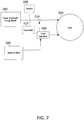
- the inhaler device comprising: a first conduit for conducting a carrier airflow to a proximal opening of a mouthpiece from which the user inhales; a holder configured to position the dose cartridge at a dose cartridge position defined by the holder within the carrier airflow of the first conduit; a second conduit, pneumatically coupled to the first conduit, for conducting a shunting airflow to the mouthpiece without passing the shunting airflow through the dose cartridge position; and at least one valve in at least one of the first and second conduits; wherein the at least one valve is operated by a valve controller to control a rate of carrier airflow in response to a negative pressure generated by the inhaling user.
- the inhaler device comprises at least one sensor positioned and configured for detecting at least one parameter indicating a rate of the carrier airflow.
- the at least one sensor comprises a pressure sensor positioned in the first conduit proximal to the dose cartridge position.
- the valve controller is functionally connected to receive an indication of the rate of the carrier airflow from the at least one sensor, and to operate the at least one valve based on the indication of the rate of the carrier airflow and a target profile for the carrier airflow.
- the indicating parameter comprises a rate of the carrier airflow sensed while the second conduit is at least partially obstructed.
- the valve controller is configured to operate the at least one valve based on a difference between the target profile and the rate of the carrier airflow sensed while the second conduit is at least partially obstructed.
- the controller is configured to modify the target profile based on the received indication of the rate of carrier airflow.
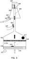
- the second conduit is connected to at least the first conduit at a junction between the dose cartridge position and the proximal opening of the mouthpiece, and the junction is configured to conduct airflow from the second conduit to circumferentially surround the carrier airflow.
- the valve controller is configured to substantially reduce a total rate of airflow to the user for an intermediate period after a first period of airflow.
- the substantial reduction in the rate of total airflow is to no more than 50% of the total rate of airflow during the first period of airflow.
- the bypass airflow through the third conduit is controlled by a bypass valve.
- the third conduit comprises a plurality of tracts.
- the inhaler device comprises a bypass valve controller functionally connected to operate the bypass valve to control airflow through the third conduit.
- valve controller and/or bypass valve controller are configured to substantially reduce a total rate of airflow to the user for an intermediate period after a first period of airflow, and then open at least the third conduit.
- a summed cross-sectional area of the proximal openings of the first and third conduits is at least 25% larger than the proximal opening of the first conduit.
- a minimal cross section through which the flow passes to the user along the third conduit is at least 25% larger than a minimal cross section through which the flow passes to the user through the first conduit.
- the at least one valve and at least one bypass valve comprise a plurality of valve apertures arranged on a mounting movable at least from a first position to a second position, such that moving to the second position aligns a valve aperture to close of one of the conduits, while also aligning a valve aperture to at least partially open another of the conduits.
- the mounting comprises at least one rotating disc having at least one valve aperture passing therethrough, and the rotating disc is rotatable at least from the first position to the second position to change the alignment of the aperture to the conduit.
- the mounting comprises: at least one inner tube having apertures into the conduits; and at least one outer tube having a wall surrounding the inner tube and having the at least one valve aperture through the wall of the at least one outer tube; wherein the at least one outer tube and the at least one inner tube are movable with respect to the other at least from the first position to the second position to change the alignment of the apertures to the conduits.
- the at least one outer tube comprises two separately movable outer tubes; and wherein moving one of the two separately movable outer tubes controls the degree of opening of one conduit, and moving the other controls the degree of opening of another conduit.
- the inhaler device comprises a heating assembly configured to heat material of the drug dose cartridge comprising the at least one drug substance to vaporize the at least one drug substance from the material, wherein the released vapors flow into the first conduit and enter the carrier airflow.
- the heating assembly comprises an electrode configured to apply an electric current to an electrically resistive heating element of the dose cartridge, when the dose cartridge is positioned by the holder.
- the inhaler device comprises: at least one sensor positioned and configured for detecting at least one parameter indicating a rate of the carrier airflow; and a heating controller functionally connected to control heating of the material of the drug dose cartridge, based on the at least one parameter indicating the rate of carrier airflow.
- the heating controller is configured to stop heating if the rate of carrier airflow drops below a threshold.
- the heating controller is functionally connected to receive an indication of the temperature from the temperature sensor, and to operate the at least one valve based on the indication of the temperature.
- the valve controller operates the at least one valve to reduce the carrier airflow if the temperature falls below a threshold.
- the target profile comprises a constant flow rate through the first conduit and the dose cartridge position for at least a certain period.
- the heating controller is configured to activate drug substance release when commencement of inhalation by the user is detected or when the rate of carrier airflow is above a threshold.
- At least the valve controller is configured to communicate with one or more of a user interface and a physician interface.
- the at least one valve is operable by the valve controller based on one or more of: a flow rate of inhalation, a flow rate through the dose cartridge position, and a defined time from a detected or estimated event.
- the inhaler device comprises a fan positioned to affect carrier airflow through the first conduit.
- a fan controller is functionally connected to operate the fan to induce airflow based on the indication of the rate of carrier airflow from the sensor and a target profile for the carrier airflow.
- the at least one valve comprises a valve positioned along the first conduit.
- the at least one valve comprises a valve positioned along the second conduit configured to at least partially close to limit a rate of shunting airflow, and thereby to affect the rate of carrier airflow.
- the valve controller comprises a portion of the at least one valve mechanically configured to adjust a degree of opening of the at least one valve based on at least one of the shunting airflow and the carrier airflow.
- the holder positions the dose cartridge such that at least 90% of the carrier airflow through the first conduit passes through the dose cartridge.
- the second conduit is connected to the first conduit at a junction located between the dose cartridge position and the proximal opening of the mouthpiece.
- At least one of the first and second conduits comprises a plurality of airflow tracts.
- an inhaler device for delivery to an inhaling user of at least one drug substance emitted from a dose cartridge, the inhaler device comprising: an at least first conduit for conducting at least a carrier airflow to a proximal opening of a mouthpiece from which the user inhales; a holder configured to position the dose cartridge at a dose cartridge position defined by the holder within the carrier airflow of the at least first conduit; a bypass conduit configured to conduct a bypass airflow to the proximal opening of the mouthpiece through a path separated from the at least first conduit; and a controller configured for controlling at least the bypass airflow during a single inhalation such that the rate of total airflow to the proximal opening of the mouthpiece in a first inhalation period is significantly less than a rate of total airflow to the proximal opening of the mouthpiece in a later inhalation period.
- the rate of total airflow in the later inhalation period is at least 100% larger than during the first inhalation period.
- the controller is configured to control flow through the device during a period intermediate to the first inhalation period and the later inhalation period such that a total rate of airflow to the proximal opening of the mouthpiece during the intermediate period is significantly lower than in the first inhalation period.
- the rate of total airflow in the first inhalation period is at least 100% larger than during the intermediate inhalation period.
- the bypass conduit is connected to the first conduit at a junction between the dose cartridge position and the proximal opening of the mouthpiece, and the junction is configured to conduct the bypass airflow to circumferentially surround the carrier airflow.
- an inhaler device for delivery to an inhaling user of at least one drug substance emitted from a dose cartridge, the inhaler device comprising: an at least first conduit for conducting at least a carrier airflow to a proximal opening of a mouthpiece from which the user inhales; a holder configured to position the dose cartridge at a dose cartridge position defined by the holder within the carrier airflow of the at least first conduit; a bypass conduit configured to conduct a bypass airflow to the proximal opening of the mouthpiece through a path separated from the at least first conduit; and a controller configured for controlling at least the bypass airflow and the carrier airflow during a single inhalation such that the rate of total airflow to the proximal opening of the mouthpiece in an intermediate inhalation period is significantly less than a rate of total airflow to the proximal opening of the mouthpiece during both a later and an earlier inhalation period.
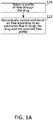
- a method of pulmonary delivery of at least one drug substance from a heated drug dose to a user inhaling from an inhaler device comprising: estimating a rate of release of the drug substance from the heated drug dose to an inhalation-induced carrier airflow passing the drug dose cartridge; controlling at least one of the heating of the drug dose and the rate of carrier airflow such that the drug substance release matches a target profile of drug substance release.
- estimating the rate of release comprises estimating a rate of carrier airflow through the drug dose cartridge.
- the rate of carrier airflow is adjusted by dynamically controlling an inhalation-induced shunting airflow which bypasses the drug dose cartridge.
- the shunting airflow is conducted to circumferentially surround the carrier airflow, such that airflow comprising a relatively high drug substance concentration is surrounded by airflow comprising a lower drug substance concentration.
- the method comprises estimating a total inhalation rate by limiting airflow in the device to carrier airflow, such that the estimated rate of carrier airflow is equivalent to a total inhalation flow rate, and controlling to match the target profile of drug substance release based on the estimated total inhalation flow rate.
- a heating pattern applied to the drug dose is adjusted to match a target profile of drug substance release.
- adjustment of the heating pattern includes controlling at least one of a rate of heating, a frequency of applying heating, a target temperature and a period of time in which one or more given temperatures are maintained.
- a target profile of drug substance release is at least partially specified by heating of the drug dose as a function of the rate of carrier airflow.
- a target profile of drug substance release is at least partially specified by the rate of carrier airflow as a function of the heating of the drug dose.
- the controlling comprises modifying a pressure differential across the drug dose cartridge.
- the controlling comprises adjusting the opening of one or more valves.
- the target profile of drug substance release is at least partially specified in terms of a rate of carrier airflow.
- the specified rate of carrier airflow comprises a constant rate of carrier airflow for a certain period.
- the target profile of drug substance release is at least partially specified in terms of the heating of the drug dose.
- the specified heating of the drug dose comprises maintaining a drug dose temperature for a certain period.
- the method comprises modifying the target profile during while the user is inhaling.
- the heated drug dose comprises a botanical substance, and the heating is applied to vaporize the at least one drug substance.
- the botanical substance comprises cannabis
- the at least one drug substance comprises THC
- the method comprises flushing drug dose residues from at least one of a conduit of the inhaler device and a dose cartridge by allowing only carrier airflow through the device.
- the method comprises flushing drug dose residues by allowing only carrier airflow for a period after heating of the material is stopped.
- an inhaler device for providing to an inhaling user a flow-based status indication, the inhaler device comprising: at least one conduit for conducting airflow to a mouthpiece from which the user inhales; at least one valve operable to modulate resistance to the airflow conducted through the conduit; and a controller functionally connected to the control the valve to generate a pattern of airflow modulations indicating a status of the inhaler device to the user.
- the pattern of airflow modulations indicates successful operation of the inhaler.
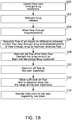
- a method of manipulating flow through an inhaler device to provide a respiration-based indication to a user inhaling through the inhaler device comprising: allowing a first period of airflow through the inhaler device during an inhalation; at least partially obstructing the airflow so that a reduction in flow is sensed by the user; allowing a second period of less obstructed airflow through the inhaler device during a continuation of the same inhalation.
- airflow during the first period carries a drug substance from the inhaler to the pulmonary system of the user, and wherein airflow during the second period advances a drug substance inhaled during the first period deeper within the pulmonary system.
- a rate of airflow during the first period is controlled based on a target profile of flow through a drug dose cartridge carrying the drug substance and held within the inhaler device.
- the releasing is ceased before the obstructing.
- a rate of airflow during the second period is at least 50% greater than during the first period.
- a sequence of flow manipulations indicates to the user that a use session is completed.
- the device is configured to provide the user with an additional audio, visual and/or tactile indication that a use session is completed.
- At least one of the allowing a first period of airflow, obstructing the airflow and allowing a second period of less obstructed airflow is performed such that a total volume of flow reaching the user during the second period is larger than a volume of an anatomical dead space of the user.
- the period of obstructing is selected according to a sensed parameter of the airflow during the first period.
- the sensed parameter comprises a rate of airflow.
- the period of obstructing is extended when a low inhalation flow rate is sensed during the first period.
- the length of the period of obstructing is based on allowing inhalation effort measured during the first period to continue long enough that a negative pressure develops causing a calculated minimum volume to be inhaled once airflow resumes in the second period.
- the degree of obstructing is selected according to a sensed parameter of the pressure during the obstruction period.
- the at least partial obstructing of the airflow is increased when a sensed parameter of the pressure during the obstruction period indicates an inhalation force below a threshold.
- the at least partially obstructing the airflow is performed for a period of between 5 and 400 msec.
- a inhaler device comprising: at least one inner tube comprising a wall having at least one aperture in pneumatic communication with a central conduit extending longitudinally within the inner tube; and at least one outer tube having a wall surrounding at least a portion of the at least one inner tube and having at least one aperture through the wall of the at least one outer tube; wherein the at least one outer tube and the at least one inner tube are movable with respect to each other at least from a first position to a second position to change the alignment of the apertures in the inner and outer tubes, such that moving to the second position moves an outer tube aperture away from alignment with an inner tube aperture to reduce an opening leading to the central conduit, while also aligning an outer tube aperture with an inner tube aperture to increase an opening leading to the central conduit.
- the inhaler device comprises a plurality of holders.
- the first conduit comprises a plurality of drug conduit tracts
- the plurality of holders comprises holders located in corresponding drug conduit tracts.
- the plurality of holders comprises at least two holders located in a common drug conduit tract.
- the holder positions the dose cartridge within the first conduit such that such that the electrode of the heating assembly is sealed from the carrier airflow.
- the holder positions the dose cartridge such that substantially all of the carrier airflow through the first conduit passes through the dose cartridge.
- an inhaler device for delivery to an inhaling user of at least one drug substance emitted from a dose cartridge
- the inhaler device comprising: a holder configured to position the dose cartridge at a dose cartridge position defined by the holder, the defined position being such that the least one drug substance emitted from the dose cartridge enters a carrier airflow; a first conduit for conducting the carrier airflow from the dose cartridge position to a proximal opening of a mouthpiece from which the user inhales; a second conduit, pneumatically coupled to the first conduit, for conducting a shunting airflow to the mouthpiece without passing the shunting airflow through the dose cartridge position; and at least one valve in at least one of the first and second conduits; wherein the at least one valve is operated by a valve controller to control a rate of carrier airflow in response to a negative pressure generated by the inhaling user.
- an inhaler device for delivery to an inhaling user of at least one drug substance emitted from a dose cartridge
- the inhaler device comprising: a holder configured to position the dose cartridge at a dose cartridge position defined by the holder, the defined position being such that the least one drug substance emitted from the dose cartridge enters a carrier airflow; a first conduit for conducting the carrier airflow from the dose cartridge position to a proximal opening of a mouthpiece from which the user inhales; and a second conduit, connected to the first conduit at a junction between the dose cartridge position and the proximal opening of the mouthpiece, for conducting a shunting airflow to the mouthpiece without passing the shunting airflow through the dose cartridge position; wherein the junction is configured to conduct airflow from the second conduit to circumferentially surround the carrier airflow.
- aspects of the present invention may be embodied as a system, method or computer program product. Accordingly, aspects of the present invention may take the form of an entirely hardware embodiment, an entirely software embodiment (including firmware, resident software, micro-code, etc. ) or an embodiment combining software and hardware aspects that may all generally be referred to herein as a "circuit," "module” or “system.” Furthermore, some embodiments of the present invention may take the form of a computer program product embodied in one or more computer readable medium(s) having computer readable program code embodied thereon. Implementation of the method and/or system of some embodiments of the invention can involve performing and/or completing selected tasks manually, automatically, or a combination thereof. Moreover, according to actual instrumentation and equipment of some embodiments of the method and/or system of the invention, several selected tasks could be implemented by hardware, by software or by firmware and/or by a combination thereof, e.g ., using an operating system.
- a data processor such as a computing platform for executing a plurality of instructions.
- the data processor includes a volatile memory for storing instructions and/or data and/or a non-volatile storage, for example, a magnetic hard-disk and/or removable media, for storing instructions and/or data.
- a network connection is provided as well.
- a display and/or a user input device such as a keyboard or mouse are optionally provided as well.
- the computer readable medium may be a computer readable signal medium or a computer readable storage medium.
- a computer readable storage medium may be, for example, but not limited to, an electronic, magnetic, optical, electromagnetic, infrared, or semiconductor system, apparatus, or device, or any suitable combination of the foregoing.
- a computer readable storage medium may be any tangible medium that can contain, or store a program for use by or in connection with an instruction execution system, apparatus, or device.
- a computer readable signal medium may include a propagated data signal with computer readable program code embodied therein, for example, in baseband or as part of a carrier wave. Such a propagated signal may take any of a variety of forms, including, but not limited to, electro-magnetic, optical, or any suitable combination thereof.
- a computer readable signal medium may be any computer readable medium that is not a computer readable storage medium and that can communicate, propagate, or transport a program for use by or in connection with an instruction execution system, apparatus, or device.
- Program code embodied on a computer readable medium and/or data used thereby may be transmitted using any appropriate medium, including but not limited to wireless, wireline, optical fiber cable, RF, etc., or any suitable combination of the foregoing.
- Computer program code for carrying out operations for some embodiments of the present invention may be written in any combination of one or more programming languages, including an object oriented programming language such as Java, Smalltalk, C++ or the like and conventional procedural programming languages, such as the "C" programming language or similar programming languages.
- the program code may execute entirely on the user's computer, partly on the user's computer, as a stand-alone software package, partly on the user's computer and partly on a remote computer or entirely on the remote computer or server.
- the remote computer may be connected to the user's computer through any type of network, including a local area network (LAN) or a wide area network (WAN), or the connection may be made to an external computer (for example, through the Internet using an Internet Service Provider).
- LAN local area network
- WAN wide area network
- Internet Service Provider for example, AT&T, MCI, Sprint, EarthLink, MSN, GTE, etc.
- These computer program instructions may also be stored in a computer readable medium that can direct a computer, other programmable data processing apparatus, or other devices to function in a particular manner, such that the instructions stored in the computer readable medium produce an article of manufacture including instructions which implement the function/act specified in the flowchart and/or block diagram block or blocks.
- the computer program instructions may also be loaded onto a computer, other programmable data processing apparatus, or other devices to cause a series of operational steps to be performed on the computer, other programmable apparatus or other devices to produce a computer implemented process such that the instructions which execute on the computer or other programmable apparatus provide processes for implementing the functions/acts specified in the flowchart and/or block diagram block or blocks.
- the present disclosure in some embodiments thereof, relates to pulmonary delivery of a drug substance using a personal inhaler device and, more particularly, but not exclusively, to controlling flow through an inhaler.
- control of flow through the inhaler comprises dynamic control over the flow of ambient air.
- an amount of drug substance that is delivered to the patient from a drug dose is controlled.
- a broad aspect of some embodiments relates to controlled pulmonary delivery of one or more active substances of a drug dose to a user.
- delivery is performed via a personal inhaler device.
- a targeted profile comprises a target temperature, range of temperatures, and/or time-evolving temperature or range of temperatures which the drug dose is heated to.
- a targeting profile comprises heating effected intermittently.
- a targeted profile comprises a targeted profile of flow, for example as described hereinbelow.
- a targeted profile comprises a function, lookup table, or other description indexing flow and temperature characteristics together. For example, in some embodiments, as airflow increases, more of the heat delivered to a drug dose for drug substance vaporization is potentially drawn away.
- a targeted profile of release (for example to achieve a particular rate of release) specifies that as an airflow increases, so does a delivery of heat.
- a potential advantage of this is to allow a more concentrated release of drug substance, while preventing overheating which could cause damage to the device, the drug substance, and/or injury to the user.
- a longer release time is targeted.
- heating is maintained to a level which keeps a temperature of the drug dose just above a minimum effective vaporizing temperature, for example, within 1° C, within 2° C, within 5° C, within 10°C, or within another higher, lower or intermediate temperature above a minimum effective vaporizing temperature.
- Effective vaporizing is at a rate, for example, of 10% of the total dose substance per second, 20%/s, 30%/s, 50%/s, or another higher, lower, or intermediate Lower airflow is adjusted for by lowering the heating.
- heating and flow rate control are adjusted to compensate for limits in the range of control that each other allows.
- heating control reaches a limit of available power
- flow is increasingly restricted, to prevent over-cooling of the drug dose.
- limits to the level of flow for example, a minimum flow to ensure good transfer of drug substance to the user
- the delivery of heat is regulated.
- a release profile is matched in terms of operational parameters.
- a release profile which targets releasing all of a drug substance of a drug dose over a period of 2 seconds is defined in terms of operational parameters which heat the drug and/or control flow so that the 2 second release time target is matched.
- the operations parameters are determined, for example, empirically, and/or by use of models comprising known characteristics of the drug substance and/or the drug dose.
- one or the other of the control possibilities is used dominantly for control of a target profile of release.
- carrier flow is left substantially unregulated, while heating is varied to maintain a target temperature.
- heating is substantially constant, while carrier flow is regulated to produce an even (or other targeted) flow.
- An aspect of some embodiments relates to controlling heating of a drug dose according to a sensed temperature indication and a targeted profile.
- temperature is measured by, for example, an infrared sensor, and/or by a contact thermal sensor.
- the temperature indication is calibrated to a temperature in degrees.
- the temperature indication is used operationally to set a particular level of heating. It is a potential advantage to control temperature based on sensed feedback, to help ensure that a targeted profile of drug substance release is met.
- An aspect of some embodiments relates to controlling carrier gas flow (for example, airflow; also referred to as "carrier airflow" herein) through or adjacent a drug dose according to a determined profile, by providing shunting airflow based on a difference between an estimated flow through the drug dose, and the targeted profile of flow through the drug dose.
- a volumetric flow rate through the drug dose is measured or estimated, for example using one or more sensors; and a flow of a gas (optionally, flow of ambient air), is dynamically modified based on the indication from the sensor(s).
- the flow rate through the drug dose is equivalent to an inhalation flow rate of the user. It should be understood that the control of flow rate is optionally co-regulated with temperature control, for example as described hereinabove.
- an inhalation flow rate of the user is estimated in accordance with an indication provided by the one or more sensors.
- the indication from the one or more sensors is combined with a current opening status of one or more valves that control the flow into and/or out of and/or within the inhaler device.
- airflow control includes dynamically modifying the flow of shunting airflow and/or shunting airflow relative to carrier airflow. This allows supplying the user with a flow rate at least partially governed by the act of inhalation (for example, not oversupplied with respect to a rate of inhalation), while maintaining the flow rate through the drug dose at an essentially fixed rate and/or within a specific profile.
- a target profile comprises or consists of maintaining the flow through the drug dose at a constant rate; for example, 0.5 L/min, 1 L/min, 4 L/min, or an intermediate, higher or lower rate of flow.
- the profile of flow through the drug dose comprises a varying flow profile, for example including a linearly increasing rate, linearly decreasing rate and/or any other profile.
- target profile means a pattern of features of airflow through an inhaler device, including one or more of: a rate of flow, a period of flow, and a distribution of flow between different conduits and/or different tracts of the device.
- a target profile optionally includes a plurality of target profiles, and optionally the timing, duration, and/or a degree of overlap between such target profiles.
- a device having a plurality of conduits, at least one of which provides passage through a drug dose optionally has a target profile including a period during which at least one (sub-target profile is imposed on flow through the drug dose and at least one other (sub-target profile is defined by a degree of drag, obstruction, and/or flow resistance imposed on inhalation flow drawn by a user through the device.
- a target flow profile through the drug dose is selected to control an amount of drug substance released, control timing of drug substance delivery, to set an inhalation depth, to target a location for drug delivery within the body of the user, and/or control a profile of active substances released from the drug dose (for example by selecting a flow profile that will initially release a first drug substance and only at a later stage of inhalation release a second drug substance).
- more than one drug dose substrate is contained within a drug dose cartridge of the inhaler device.
- release of one or more drug substances is controlled in accordance with a size (e.g . molecular size), weight, or another chemical or physical property of a drug substance.
- commencement of inhalation is detected, for example when the measured inhalation flow rate is above a predefined threshold.
- this threshold is a flow rate through the drug dose which is equal to the value that is to be maintained for at least part of a target flow pattern. In some embodiments this is a value that is to be maintained (constantly or intermittently) for at least 0.25 or even 0.5 seconds. In some embodiments this rate is 0.5 L/min, 1 L/min or even 2 L/min, or an intermediate rate of flow.
- commencement of inhalation triggers activation of drug substance release.
- drug substance release involves processing of the drug dose, for example by heating the drug dose to extract one or more active substances.
- the drug dose comprises plant material, for example cannabis and/or tobacco, and an active substance (e.g . THC and/or nicotine) is extracted by heating the plant matter.
- plant material examples include one or more of Cannabis sativa , Cannabis indica , Cannabis ruderalis, Acacia spp., Amanita muscaria, Yage, Atropa belladonna , Areca catechu, Brugmansia spp., Brunfelsia latifolia , Desmanthus illinoensis, Banisteriopsis caapi , Trichocereus spp., Theobroma cacao , Capsicum spp., Cestrum spp., Erythroxylum coca, Solenostemon scutellarioides , Arundo donax , Coffea arabica , Datura spp., Desfontainia spp., Diplopterys cabrerana, Ephedra sinica , Claviceps purpurea , Paullinia cupana , Argyreia nervosa, Hyoscyamus niger, Tab
- the dosing botanical substance optionally includes any combination of plant material from this list, and/or other plant material.
- the drug dose comprises one or more synthetic or extracted drugs added to or applied on carrier material, wherein the added drug and/or the drug dose may be in the form of or comprise solid material, gel, powder, encapsulated liquid, granulated particles, and/or other forms.
- the drug dose comprises plant material having one or more synthetic or extracted drugs added thereto or applied thereon.
- a structure of the personal inhaler device includes one or more first conduits within which air entering the inhaler device flows through the drug dose; at least one second, shunting conduit in pneumatic communication with the first drug conduit, through which shunting airflow (which avoids the drug dose itself) may be allowed to join the flow that had already passed through the drug dose; optionally a third, bypass conduit through which ambient air (e.g. a flow not carrying a drug substance) may be allowed to flow directly to the user; and a regulating mechanism for controlling flow through the one or more conduits, for example comprising one or more valves.
- air flows into the first conduit in response to pressure reduction produced in the device during inhalation.
- first conduit(s) together with the second, and/or third conduit(s) join to produce a combined flow.
- two or more of the conduits unite in proximity to and/or within the mouthpiece of the inhaler device.
- an "at least one first conduit” (or second or third conduit, and/or drug, shunting, or bypass conduit) is also equivalently referred to herein as "a first" (or other) "conduit comprising at least one tract”.
- a single conduit for one of the drug substance-bearing, shunting, or bypass airflow functions is optionally comprised of two, three, or more tracts.
- At least one flow rate sensor is positioned within the device, at a location suitable to detect a rate of flow that passed through the drug dose, for example being positioned within the drug conduit distally to a connection between the shunting conduit and the drug conduit.
- input from the sensor is received on a controller of the inhaler device, which in turn operates the one or more valves accordingly.
- the controller will open at least one shunting conduit to allow ambient flow at a rate of 2 L/min into the drug conduit, thereby reducing the upcoming flow rate through the drug dose to the target 1 L/min, while still providing the user with a rate of 3 L/min, similar to the inhaled rate.
- a valve which operates to control a flow rate through a drug carrier conduit by a relative opening or closing which controls a flow rate in a shunt conduit is termed a "shunt valve" herein.
- a shunt valve is optionally located within a shunt conduit; additionally or alternatively, it is located in a drug conduit.
- An aspect of some embodiments relates to a sequence of flow manipulations through an inhaler device, which provides a perceptible indication to a user.
- the sequence of flow manipulations comprises a significant reduction in the flow through the device, optionally to a full obstruction, which is optionally followed by allowing resumed flow.
- allowing resumed flow includes allowing a rapid flow, being significantly faster than before the reduction.
- the partial obstruction of flow includes obstructing all flow through the device other than flow through drug dose, to flush residual released drug substance into and/or from the conduit.
- the partial obstruction of flow includes a full obstruction (or almost full), in which all conduits are blocked to significantly reduce pressure in the conduits, enough to be sensed by the user. Potentially, by attempting to inhale against partial or full obstruction, a user naturally increases inhalation effort, creating increasingly negative pressure within the device.
- the partial obstruction is followed or replaced by the full or almost full obstruction.
- a rapid pulse of flow is allowed by opening at least the bypass (third) conduit, to allow ambient airflow directly to the user. Additionally or alternatively, the drug conduit and/or the shunting conduit are opened as well.
- drag forces are reduced, reducing a resistance encountered by the user when inhaling through the device.
- reduction of drag forces is obtained by allowing the rapid flow through an opening having a cross sectional area substantially larger than the cross sectional area through which drug substance infused flow was provided.
- the pulse of flow includes a total volume which is about equal to or even larger than an anatomic dead space of the user, for example 150 ml or larger, chasing the drug substance deeper into the lungs, potentially ensuring deep lung delivery, and/or reducing the amount of drug substance exhaled immediately after using the inhaler.
- An aspect of this disclosure relates to producing circumferential airflow when delivering a drug substance through a conduit, in which flow comprising a higher drug substance concentration is surrounded by flow comprising a lower drug substance concentration.
- This may be seen as a "sleeve-like" effect of laminar flow wherein the circumferential airflow flows around air that passed through the drug dose with little mixing, thereby reducing contact of released drug substances with conduit walls.
- the sleeve-like effect is obtained by allowing entry of shunting flow, for example through the shunting conduit(s), into the first conduit to join carrier airflow that has already passed through the drug dose.
- the flow through the shunting conduit(s) is provided through a plurality of openings surrounding the conduit.
- flow rate is controlled to keep flow in a laminar (substantially non-turbulent) flow regime, at least near the conduit walls.
- flow velocity leading to a Reynolds number of 2100 or less is maintained.
- critical Reynolds number below which flow maintains laminar characteristics varies according to the particular geometry of the conduit.
- a double sleeve-like effect is obtained by allowing more ambient flow at positions more proximal than the aforementioned. This may be performed, for example, by having two or more sets of tracts of the shunting conduit(s) which provide ambient air sequentially along the flow path. Additionally or alternatively, a double sleeve-like effect is obtained by opening the bypass conduit(s) so that at least at a proximal portion of the mouthpiece all flow is united, while the air with the highest drug substance concentration flows through a substantially center of the conduit.
- a potential advantage of a sleeve-like effect may include reducing adherence of drug dose residues and/or active substances to the walls of the conduit, which may be especially advantageous when the drug dose comprises oily materials, for example comprising plant material such as cannabis.
- An aspect of some embodiments is the control of an inhaler device to produce changes in a flow profile (for example, a flow profile which adjustably regulates flow through a plurality of conduits) by the movement of a mechanism which provides control over two or more valves at once.
- the mechanism comprises at least two apertured elements, for example, at least two disks or at least two cylinders. Movement (for example, rotation and/or straight line translation) of one apertured element relative to the other element changes the relative alignment of the apertures.
- apertures are arranged so that a plurality of valves (for example, valves to a carrier conduit) are opened and closed together by a single movement.
- apertures are arranged so that at least one valve opens while another valve closes.
- apertures are arranged so that valve opening and closing can be performed relatively separately among two or more valves, depending on the motion and/or relative position of the valve members.
- ambient air includes air entering a conduit of the device.
- Ambient air optionally comprises room air or any modification thereof, such as addition of one or more drug substances to the air, humidification of the air, and/or other modifications.
- ambient air relates to air that flows to the user via a conduit without passing along or via the drug dose.
- proximal is used in reference to a portion, component and/or opening of the inhaler device in relative proximity to the user end during an inhalation event, e.g. a mouthpiece.
- a component may be physically “distal” or “proximal”, and/or it may be at a position that is relatively more distal or proximal than another position.
- distal is used in reference to a portion, component and/or opening of an inhaler device which is closer to an end of the device opposite the user end.
- a component is described as functionally or operationally “distal” or “proximal”.
- distal could be used in reference to a conduit opening through which air initially enters the device, before advancing through the path of flow to the user, regardless of the physical position of the opening with respect to the user end.
- drug substance or “active substance” is used in reference to one or more pharmaceutically or otherwise active substances, for example therapeutic or medicinal substances and/or substances for recreational use, and/or substances for testing.
- an “active” substance is such substance which may have an effect on a user's body or any part thereof.
- a “drug substance” may be administered to a user, for example by vaporization, suspension, and/or volatilization of the drug substance into gas (typically air) inspired by a user.
- a drug substance includes one or more non-active materials accompanying the active portion of the drug substance.
- drug dose denotes material, arranged for use in an inhaler device, from which one or more drug substances are released ( e.g . extracted or vaporized). In some embodiments the material comprises the one or more drug substances.
- a drug dose is optionally arranged, for example, as a pallet of the drug dose material.
- drug cartridge and “drug repository” include structures that are configured for the handling and/or structure maintenance of a drug dose (for example, for supporting a drug dose pallet), including, for example, one or more of: a carrier, housing, frame, packaging, or other structure associated with the drug dose material itself; this is also referred to as a "dose unit” or "drug dose unit".
- the drug dose together with all additional structures is configured to permit airflow through the drug dose at least at a rate of 0.5 L/min, 1 L/min, 4 L/min, or an intermediate, higher or lower rate of flow.
- Figures 1A-1B are schematic flowcharts of general ( Figure 1A ) and detailed ( Figure 1B ) methods for pulmonary delivery of one or more drug substances to a user using an inhaler device, according to some embodiments of the invention.
- Figure 1A is a general method of controlling flow through an inhaler device.
- a target profile of air flow through the drug dose is optionally selected (block 120 ).
- selecting the target profile comprises selecting one or more parameters such as flow rate, total volume, duration, flow velocity, and/or other parameters of the flow that passes through the drug dose and/or through one or more conduits of an inhaler device.
- a target profile is selected prior to providing the drug substance to the user through the inhaler device (for example, during manufacturing of the device, and/or during a previous configuration of the device). Additionally or alternatively, the profile is selected and/or modified during a use session, for example during an inhalation of the user through the inhaler device.
- the profile is selected before a new use (e.g. use by a different user and/or for a different drug substance or different drug substance concentration).
- the profile is determined in the process of design or manufacture of the device, such that the device can operate only according to the predefined profile without necessarily performing an act of selection during use.
- shunting air flow into the device is dynamically controlled according to an estimated flow through the drug dose and the target flow profile through the drug dose (block 122 ).
- shunting air flow unites with flow that had already passed through the drug dose.
- shunting flow is allowed into the inhaler device (for example by opening a valve) in response to a difference between the estimated flow through the drug dose, and the target flow profile through the drug dose.
- an inhaler device suitable for implementation of a method comprises at least a first conduit through which one or more active substances are delivered to the user (the first conduit will be hereinafter referred to as "drug conduit").
- This drug conduit passes through a drug repository where the drug substance or one or more active substances are added to air flowing through the repository; a second conduit that joins the drug conduit at a more proximal location along the drug conduit, in which air has already flown past the drug repository, allowing ambient air to enter and join the drug substance-infused air that passed via the repository, thereby increasing a volume of the air flowing through the drug conduit (the second conduit will be hereinafter referred to as "shunting conduit”); optionally a third conduit conducting ambient air directly to the user (the third conduit will be hereinafter referred to as a "bypass conduit”); and one or more regulating means (for example valves), for controlling flow into the inhaler device, flow through the conduits and/or in between the conduits, and/or flow out of the inhaler device.
- regulating means for example valves
- the drug conduit and the bypass conduit lead the flow to a common passage, for example a passage through the mouthpiece.
- the method comprises detecting a flow rate through a drug repository.
- flow rate through the drug dose is indicative to the inhalation flow rate of a user (block 100 ).
- flow rate is detected by one or more sensors, for example a differential pressure sensor. Additionally or alternatively, flow rate is sensed and/or adjusted mechanically, for example using pressure release valves, duck billed valves, and/or the like.
- commencement of inhalation is detected, for example by measuring a flow rate that is above a defined threshold.
- a flow rate is measured continuously during inhalation.
- a flow rate is measured occasionally or periodically during inhalation; for example: every 10 msec, every 50 msec, every 100 msec, every 500 msec, every second, or over intermediate, longer or shorter time periods.
- flow rate measurement is performed within the drug conduit, at a location distal to a junction between a shunting conduit and a drug conduit.
- drug substance release is activated (block 102 ).
- commencement of inhalation triggers activation (e.g . when a sensed flow rate is significantly greater than zero).
- drug substance release is activated only when air flow through the drug dose is sensed to be above a higher threshold.
- this threshold equals a flow rate through the drug dose that is maintained constant for at least a portion of an inhalation event. In some embodiments, this threshold is 1 L/min, 0.5 L/min, 2 L/min, or an intermediate, higher or lower flow rate.
- drug substance release is activated additionally or alternatively subject to being prompted by a user, for example by pressing a button or shifting the inhaler device to a ready-to-use position.
- activation of drug substance release comprises evacuating one or more active substances of the drug dose.
- evacuation comprises one or more of heating, vaporizing, initiating a chemical reaction, changing a physical state of the drug dose material (e.g . turning to aerosol), simply allowing air to flow through the drug repository and carry the drug substance, and/or other methods suitable for releasing and/or extracting the drug substance to deliver it to the user.
- drug substance release is activated for a defined time period.
- drug substance release is activated for a time period which is dynamically adjusted, for example based on the flow rate measurement.
- air entering the inhaler in response to suction produced in the device during inhalation flows through the drug conduit, passing the drug repository (block 104 ).
- all other conduits are obstructed at this stage.
- a target flow profile through the drug repository is maintained by regulating flow of ambient air (block 106 ), such as air entering through the shunting conduit.
- flow of ambient air is regulated based on differences between the current flow rate through the drug dose, as detected for example by the pressure sensor, and the target flow rate through the drug dose.
- a target flow profile through the drug dose comprises or consists of a constant flow rate, for example 1 L/min, 0.5 L/min, 2 L/min, or an intermediate, higher or lower flow rate, optionally for a certain period of time. Additionally or alternatively, a target flow profile comprises an increasing or decreasing flow rate. Optionally, the change in flow rate is monotonic. Optionally, the change in flow rate is linear.
- a target flow profile comprises other profiles, such as one or more of constant flow through the drug dose followed by unregulated flow through the drug dose (optionally with all other conduits closed); constant flow through the drug dose followed by allowing of rapid flow through the bypass conduit(s); constant flow through the drug dose followed by a partial or full obstruction of the conduits, and/or other profiles or combinations thereof and any other flow profile described herein.
- the target flow profile is set in accordance with one or more of the following parameters: the type of drug dose and/or substance, the amount of drug dose and/or substance, the time period required to release the drug substance, the type of processing of the drug dose (e.g. heating), and/or user parameters.
- the type of drug dose and/or substance e.g. a small child
- flow through the drug dose may be adjusted to a set maximal and/or constant value of 500 ml/min.
- a user suffers from shortness of breath, and though capable of inhaling a volume of, for example, 2 L/min, this is but for a limited time period, such as 2 seconds.
- a rate of flow through the drug dose is set to a higher value, for example 1.5 L/min.
- This higher value may be set in order to deliver in the 2 second time period an amount of drug substance nearing that which would have been provided over, for example, a 3 second time period to a user capable of longer inhalation.
- release of the one or more drug substances is accelerated, for example by modifying a heating profile.
- a target flow profile through the drug dose contributes to quantifying and/or timing drug substance release.
- a target profile of flow through the drug dose is selected to increase control over the dosage of drug substance inhaled by the user. For example, if a strong suction force is produced in the device during inhalation, air flow at a relatively high velocity will enter the device and pass through the drug dose, possibly increasing the amount of drug substance released over a target amount. In an embodiment in which the drug dose is heated, flow at a higher velocity than the target may cause premature cooling of the drug dose. Therefore, by controlling a rate of airflow through a drug dose, the amount of drug substance inhaled from a dose unit having a given composition may be essentially the same for a wide range of users.
- regulating of ambient air flow comprises allowing flow through the shunting conduit(s) ( e.g . by opening a valve to allow flow between the drug conduit and the shunting conduit and/or by controlling the extent to which it is opened) based on the measured inhalation flow rate.
- a threshold for opening the shunting conduit comprises a detected inhalation flow rate that is higher by at least 1%, at least 5%, at least 20% or an intermediate, higher or lower percentage higher than an initial target rate of flow through the drug dose, such as a rate of 1 L/min.
- the target flow profile through the drug dose is set to a constant 1 L/min, and the user's initial inhalation flow rate is measured at 3 L/min (as sensed within the drug conduit, assuming other conduits are initially closed)
- the shunting conduit will open and allow air to enter at a flow rate of 2 L/min.
- the target constant profile will then be maintained by detecting a deviation in flow rate through the drug conduit (at a distal portion of the conduit, before the joining the shunting conduit) from 1 L/min, and dynamically regulating ambient flow through shunting conduit accordingly. Assuming natural fluctuations in the inhalation flow rate of the user, the "completing" ambient flow rate that is allowed into the device will vary at various time points during inhalation.
- the sensed flow rate would be approximately equal to the difference between the user's inhalation flow rate and the flow rate through the shunting conduit. For example, if in the above case the user's inhalation increased to 3.5 L/min, and the flow rate via the shunting conduits was set to 2 L/min, then a flow rate of about 1.5 L/min would be sensed. In such case the shunting conduit will open further to allow air to enter at a flow rate of 2.5 L/min, thereby reducing the sensed flow rate back to about 1 L/min. Likewise, if the inhalation flow rate is reduced ( e.g. to 2.5 L/min.) the shunting conduit will partially close so that air may enter at a flow rate of 1.5 L/min only.
- a potential advantage of dynamic regulation of ambient flow based on the current rate of flow or estimation thereof and the target flow profile through the drug dose includes providing a user with total volume of ambient air mixed with drug substance-infused air which is equal to the volume inhaled by the user, thereby allowing different users to breathe differently through the inhaler without significantly affecting air flow via the drug repository, and consequently the amount of inhaled drug substance.
- a measured flow rate through the drug dose which is indicative of the inhalation flow rate or a measured inhalation flow rate is lower than a threshold, for example being lower than the target flow rate required through the drug dose, such as less than 1 L/min in the example described above, drug substance release will not be activated.
- the inhaler device will provide an indication to the user (e.g. by a light indication, sound indication, tactile indication, and/or other indication) to increase air intake during inhalation. If this is sensed at a later time during operation drug substance release may be terminated, for example if the flow falls below the threshold for at least a specific period of time.
- a fan, a blower and/or other air pressure source is used with the inhaler to supply additional flow into the inhaler.
- This configuration might be specifically advantageous in an inhaler device used by weak users, elderly users, young children, and/or other users incapable of inhaling at a minimal flow rate for drug substance release.
- the fan or blower is operable in reverse. Potentially this mimics the effect of a closed or partially closed valve, acting to increase apparent resistance to air flow through a conduit.
- drug substance is released over a selected time period.
- the time period is a target time period, for example a constant time period, such as 3 seconds, 5 seconds, 1.5 seconds, or intermediate, longer or shorter time periods.
- a time period for drug substance release e.g. by heating the drug dose
- a time period for drug substance release is dynamically modified or determined during inhalation, for example based on the detected inhalation flow rate.
- the inhalation flow rate of the user is slightly under a target flow rate required through the drug dose (for example 5%, 10%, or 20% smaller)
- the time period of drug substance release is lengthened, and/or the heating profile is adjusted, to compensate for the lower flow rate; for example, lengthened from 3 seconds to 3.5 seconds.
- all flow other than flow through the drug conduit is obstructed (partially or completely), to flush the remaining drug substance and deliver it to the user (block 108 ).
- flow through the shunting conduit is gradually restricted before optionally being fully obstructed, to increase flow through the drug dose. It is noted that flushing of the drug substance may also take place when other conduits are open, albeit possibly at a slower rate.
- flow to the user is partially or fully obstructed (block 110 ).
- the blocking occurs at the termination of the inhalation (for example, the events described in relation to block 112 are skipped).
- the obstruction duration and/or degree is predefined. Alternatively, the obstruction duration and/or degree is set dynamically, for example determined according to a measured flow rate and/or a measured negative pressure buildup in the device during the obstruction period.
- the target duration of obstruction is, for example, according to the user's sensed inhalation flow rate, to be long enough to reduce the internal pressure within the device, optionally generating a vacuum strong enough to be sensed by the user and/or to produce a consequent rapid flow or volume (for example a volume larger than an anatomical dead space, such as 150 ml or larger) upon release of the obstruction.
- an obstruction duration set for a user inhaling at a relatively high flow rate will be shorter than an obstruction duration set for a user inhaling at a relatively low flow rate.
- the short duration obstruction in the higher flow rate user will be sufficient for generating suction strong enough to be sensed by the user, while the low flow rate user might need a longer time period to sense the suction.
- flow is allowed through the device and to the user, optionally at a relatively high rate. This is optionally after obstruction such as described in relation to blocks 108 and/or 110.
- the resumed flow is allowed without a prior period of flow restriction.
- the rate of the resumed flow is high enough to admit a relatively large volume of air to cause the drug substance inhaled before the obstruction to advance deeper into the lungs of the user.
- at least the bypass conduit is opened (for example, by opening of a bypass valve, optionally under the control of a bypass valve controller) to allow general ambient air flow to the user without being restricted by the drag of the drug conduit.
- the drug conduit and/or shunting conduit are opened as well.
- the duration of the advancing phase of the method is limited by the lung capacity of the user.
- the opening of pathways for the advancing is for a limited period of time, for example, less than 4 seconds, 3 seconds, 2 seconds, 1 second, or less than another greater, lesser, or intermediate period.
- at least one of the first conduit, the second conduit and the third conduit are left open for a period of time that extends beyond the end of an inhalation session.
- the conduit(s) may close in response to an action taken by the user (e.g . shifting the inhaler device to a "closed" position and/or pressing or releasing a button and/or when a device is primed for a later inhalation event or when a new inhalation is sensed).
- opening the bypass conduit effectively increases a cross section (and/or lowers a flow resistance) of the mouthpiece relative to the effective cross section (and/or flow resistance) that exists when only the drug conduit and/or shunting conduit are open.
- the effective cross section may be taken to mean a cross section that defines the drag forces resisting the flow of air to the user.
- the effective cross section may be taken to mean a minimal cross section through which the flow passes to the user.
- this effective cross section may be the sum of the minimal cross sections of all conduits through which air flows at a given point.
- the cross-sectional area of the bypass conduit is at least 25% larger than the cross-sectional area of the drug conduit, at least 50% larger, at least 100% larger, at least 200% larger, or larger by another greater, smaller, or intermediate factor.
- drag forces resisting flow to the user are reduced by the enlargement of effective cross section through the mouthpiece, allowing flow of higher velocity to the user at the same applied suction power.
- the user senses a sudden decrease in resistance when breathing through the inhaler as compared to the relatively restricted breathing during drug substance release and/or during the obstruction period.
- a full obstruction of flow optionally does not take place, and the bypass conduit is opened to allow ambient flow to the user to provide the large enough air pulse.
- an indication regarding the use state for example regarding the inhalation state is provided to the user (block 114 ).
- the indication is provided to indicate that a use session is completed, and the user may stop inhaling through the device.
- the indication optionally comprises, for example, a tone, vibration, and/or light.
- the indication comprises direct lung-inhaler device feedback obtained during use. For example, a specific pattern of inhalation that is elicited from the user by the inhaler may be included in such indication. More particularly, the indication may include the sequence of actions including, for example, allowing flow during drug substance delivery, followed by a substantial reduction in flow, optionally to a full obstruction.
- the sequence includes a following resumed pulse of air, optionally at a higher velocity and/or reduced resistance relative to one or all the preceding flow periods in the sequence.
- the indication includes preventing air flow via the device at the end of the session, such that the high resistance is sensed by the user as an ending point.
- a particular sequence of flow resistances experienced by the user indicates successful inhalation (for example, controlled flow/restricted flow/free flow), and any other pattern indicates a problem has occurs.
- one or more distinct "warning patterns" are defined; for example, a fluttering pattern, a full flow stop pattern, or another pattern of modulated flow resistances.
- an indication provided to a user by a pattern of flow resistances is combined with additional audio, visual and/or tactile indication. Potentially, this provides a more conventional indication to the user that, for example, clarifies the indication of the pattern.
- a “substantial reduction in flow” or “significant reduction in flow” means a reduction of the "rate of total airflow" to an inhaling user through the device.
- This "total airflow” relates to all flow of air through the device to the inhaling user, through all conduits, for example, a total volume flowing within a period of seconds, milliseconds, a single inhalation, or another period.
- rate of airflow is a material flow rate of gas (usually, but not only, derived from ambient air), for example, a volumetric flow rate of air.
- a “substantial reduction” in the rate of total airflow optionally includes any reduction that is sensed by an inhaling user and may include a reduction of, for example, airflow rate of 50% or more or even 75% or more or even complete or near complete obstruction with a reduction of at least 95% or even 100% in the rate of total airflow.
- the indication includes allowing flow during drug substance delivery under some resistance (e.g . drag on total airflow), followed by a release or significant reduction of the resistance (e.g . by opening a valve that allows bypass airflow that does not pass through a drag imposing constriction).
- some resistance e.g . drag on total airflow
- a release or significant reduction of the resistance e.g . by opening a valve that allows bypass airflow that does not pass through a drag imposing constriction.
- the flow rate through a device after obstruction is removed or reduced is at least 25%-50% of the flow rate before obstruction, or is approximately equal to the flow rate before obstruction. In some embodiments, the flow rate through a device after obstruction is removed or reduced (or before the change in resistance) is at least 25% larger than before obstruction (or before the change in resistance) or 50% larger, at least 100% larger, at least 200% larger, or larger by another greater, smaller, or intermediate factor. In some embodiments, where obstruction is less than complete, the flow rate after obstruction is removed or reduced is at least 50% larger than the allowed flow rate during obstruction, at least 100% larger, at least 200% larger, or larger by another greater, smaller, or intermediate factor.
- a higher allowed flow rate after obstruction or resistance is removed (or reduced) may be advantageous in facilitating faster and/or deeper and/or a higher volume of inhalation
- indication to the user is provided by a visual indication (e.g. a LED indication), a tactile indication (e.g. a vibration in the inhaler device), an audible indication, and/or any other indication.
- a visual indication e.g. a LED indication
- a tactile indication e.g. a vibration in the inhaler device
- an audible indication e.g. a vibration in the inhaler device
- Figure 2 is a schematic diagram of controlled flow through an inhaler device, according to some embodiments of the invention.
- flow throughout the inhaler device can be generally divided into three main flow paths: a first path of flow through the drug dose; a second optional path of ambient air flow that joins the first flow path; and a third optional flow path of ambient air that flows to the user without significantly affecting flow via the first flow path, for example by being provided directly to the user.
- inhalation of user 200 produces suction in the device, causing air to enter the device.
- airflow 202 entering the device flows through the drug dose.
- the drug dose and/or drug cartridge comprising the drug dose is held in position by a holder of the inhaler device.
- the holder is configured to hold the drug dose or a drug cartridge comprising the drug dose such that at least 90% of the carrier airflow passes through the drug dose. In some embodiments, at least 98% or even 100% of the carrier airflow passes through the drug dose.
- the holder may position a dose unit within a tract of the drug conduit and seal airflow around the drug dose, such that only (or mostly) airflow that passes through the drug dose reaches the mouthpiece. Optionally, the sealing prevents airflow from contacting sensitive mechanical and/or electrical components of the inhaler.
- a flow regulator 204 is positioned to dynamically govern ambient flow 206 into the inhaler device. In some embodiments, ambient air that entered the device is directed to join the flow that has already passed through the drug dose (via the second or shunting flow path). Additionally or alternatively, ambient air that entered the device flows directly to user 200 (via the third or bypass flow path).
- regulation of ambient flow 206 is performed based on a sensed flow rate which is determined at least partially by an inhalation force applied by user 200. Additionally or alternatively, regulation of ambient flow 206 is performed based on a difference between an actual rate of flow through the drug dose, and a target rate of flow through the drug dose.
- a rate of flow through the drug dose or an indication thereof is sensed by a sensor 208, configured for example distally to juncture 210 in which ambient flow 206 or part thereof joins the flow that has already passed through the drug dose.
- a rate of flow through the drug dose indicates the inhalation flow rate of the user. This indication may be acquired, for example, at the beginning of a use session, to detect commencement of inhalation, for example by measuring flow rate above a certain threshold.
- flow regulator 204 when the detected flow rate through the drug dose is higher than a target flow rate through the drug dose (the target rate), flow regulator 204 permits ambient flow 206 or part thereof to join the flow that has already passed through the drug dose. As the user continues to inhale, the upcoming flow rate through the drug dose is reduced (as the flow that forms the "difference" between the target flow and the detected flow is allowed to enter through the ambient flow path).
- the senor will detect a rate of flow through the drug dose, which may be different than the inhalation flow rate.
- the rate of ambient flow into the device will be dynamically modified to reduce or increase the upcoming rate of flow through the drug dose to the target value.
- a potential advantage of the flow control mechanism described herein may include providing the user with a flow rate that is similar to the inhalation flow rate, while maintaining flow through the drug dose at a target profile, optionally without significantly affecting the amount of drug substance that is inhaled by the user.
- flow regulator 204 permits ambient flow 206 to pass to the user without affecting the flow rate through the drug dose ( e.g. directly to the user), at least for a portion of a use session.
- ambient flow is provided to the user in parallel to the providing of flow that passed through the drug dose and/or in parallel to a mixture of flow that passed through the drug dose and ambient flow.
- ambient flow without affecting the flow rate through the drug dose is provided separately, for example when providing the user with an air pulse to advance the drug substance into the lungs, such towards the end of a use session.
- flow regulator 204 is configured to control a profile of the ambient flow (e.g. control one or more of a rate, velocity, pressure, volume and/or other parameters).
- the flow is controlled by dynamically modifying a cross sectional area of a passage through which the ambient air enters the device and/or advances within the device, such as a by valve that is shaped to allow free flow and/or partial flow and/or no flow through the passage.
- flow regulator 204 is mechanical and reacts autonomously to perceived pressures. In such cases, in some embodiments, a flow controller separate from the regulator itself is not included in the device.
- flow regulator 204 is activated by a controller 212.
- controller 212 is programmed to receive an indication from sensor 208, such as an indication of flow rate through the drug dose, and to activate regulator 204 accordingly.
- sensor 208 provides an indication of flow rate that is higher than a target flow rate through the drug dose, and controller 212 activates flow regulator 204 to permit entry of ambient flow 206, such as by at least partially opening a valve.
- the inhaler device comprises one or more additional flow sensors, such as a sensor configured within a shunting conduit to detect parameters (e.g . flow rate) of the ambient flow entering through the shunting conduit to join the flow in the drug conduit, a sensor configured within a bypass conduit to detect parameters ( e.g . flow rate) of the ambient flow entering the device, a sensor configured within the mouthpiece to detect parameters of flow exiting the device, optionally collecting data of a total volume of flow provided to the user, such as during a use session.
- additional flow sensors such as a sensor configured within a shunting conduit to detect parameters (e.g . flow rate) of the ambient flow entering through the shunting conduit to join the flow in the drug conduit, a sensor configured within a bypass conduit to detect parameters ( e.g . flow rate) of the ambient flow entering the device, a sensor configured within the mouthpiece to detect parameters of flow exiting the device, optionally collecting data of a total volume of flow provided to the user, such as during a use
- a measure of inhalation volume such as by the one or more sensors of the inhaler device, can be used as an indication of a physiological condition of the user, such as pain level. It is suggested that when a user is experiencing breakthrough pain, relatively high inhalation volumes may be observed. In some embodiments, an amount of drug substance provided to the user is modified based on the detected inhalation, optionally in real time.
- controller 212 is configured for storing data received from the one or more sensors. In some embodiments, controller 212 is configured to transmit data such as parameters of inhalation, a total volume of flow that was provided, parameters of flow that passed through the drug dose, and/or other parameters which were received as input on the controller to a user interface and/or to a physician interface.
- the user interface is configured on a hand held device, such as a smart phone, smart watch/band, personal computer, and the like. Additionally or alternatively, data is communicated to the user through the inhaler device, for example presented on a screen mounted on an external housing of the device and/or via telemetry to a separate device.
- the inhalation flow rate will be detected by the one or more sensors, which in turn will signal the controller, which in turn will provide an indication to the user to increase inhalation effort. Additionally or alternatively, the controller will operate a fan, a blower and/or other pressure source to supply the required flow, compensating for the low inhalation rate of the user. In another example if the user inhales at a rate which is lower than a threshold required for activating drug substance release, the device will not activate drug substance release and a notification may be provided to the user.
- FIG. 3 is a schematic illustration of components of a flow control system, for example as incorporated within an inhaler device, according to some embodiments of the invention.
- the system comprises a conduit 300 for delivery of one or more active substances of a drug dose.
- conduit 300 extends from a chamber 302 attached to the conduit at a position distal to the user, to (or optionally through) a mouthpiece 304 positioned at a proximal end of the conduit.
- Conduit 300 ends with an opening 306 through which the drug substance exits the conduit in the direction of a user.
- conduit 300 is shaped and/or sized to produce a drag force which increases a resistance to inhalation of the user. For example, a relatively small cross-sectional area of opening 306 of conduit 300 increases drag.
- the resistance is sensed by the user, and might induce the user to increase inhalation efforts.
- chamber 302 comprises a drug repository 310.
- the drug repository is held in position within the device by a holder.
- a drug dose within repository 310 may be in to the form of solid material, gel, powder, encapsulated liquid, granulated particles, and/or other forms.
- the drug dose is processed within the device before it is provided to the user, for example to extract one or more active substances, for example by heating.
- drug repository 310 includes plant material, for example cannabis and/or tobacco, from which one or more active substances such as THC and/or nicotine are extracted, for example as further described herein.
- a smoke-like substance may be added to the flow through the device to imitate common methods of use or treatment such as smoking of a cigarette, a cigar, a pipe or a cannabis cigarette.
- the device is fashioned to externally resemble the item used in such common uses.
- At least one sensor 314 is positioned at a location suitable for assessing one or more parameters of the flow that passes through the drug repository 310, for example within chamber 302.
- the sensor 314 is configured to measure one or more of: rate, pressure, velocity, volume of the flow, or another direct or indirect indication of flow rate.
- the flow estimation takes into consideration a fixed volume of the chamber.
- the sensor is positioned at a location in which it is less prone to damage and/or less prone to any physical, chemical or mechanical phenomena that may affect the sensor's performance.
- the senor may be positioned away from fumes, which may impede sensitivity and/or shorten the sensor's life.
- sensor 314 is positioned distal to an opening 306 which is a proximal opening of conduit 300, and proximal to a drug repository 310.
- a potential advantage of this position is to allow sensing of pressure changes at a position where change in pressure can be related to flow rate and/or total flow volume.
- chamber 302 comprises a distal opening 316 through which air enters, optionally in response to suction produced by inhalation of the user.
- a pressure source schematically shown as a fan 312 is positioned at or near distal opening 316 to actively force air into the chamber.
- a macro filter 318 extends across the opening, to reduce or prevent debris and/or other contaminating material from entering the chamber.
- fan 312 is activated (for example by a controller) in response to an indication from sensor 314, such as an indication of inhalation flow rate that is lower than a threshold needed to activate drug substance release.
- a shunting conduit 320 joins conduit 300 at a location which is more proximal to the user than a location in which flow through chamber 302 passes through the drug repository.
- shunting conduit 320 joins conduit 300 at a location which is close to a location in which flow through chamber 302 passes through the drug repository.
- ambient flow into conduit 300 through shunting conduit 320 is controlled by one or more valves 322 that optionally act as shunt valves.
- ambient flow entering the device is delivered through a bypass conduit 324 without being restricted by drag of the drug conduit 300.
- ambient flow through conduit 324 is controlled by one or more bypass valves 326.
- the effective cross-section (e.g . the opening) of bypass conduit 324 is larger than that of drug conduit 300 ( e.g. proximal opening 306 ).
- the combined effective cross sections of bypass conduit 324 and drug conduit 300 affect the flow rate through opening 308 of mouthpiece 304. Accordingly, the effective cross section of drug conduit 300 is for example at least 2 times smaller, at least 3 times smaller, at least 5 times smaller or intermediate, larger or smaller values.
- the summed cross-sectional area of the proximal openings of the bypass conduit 324 and the drug conduit 300 is at least 25% larger than the proximal opening(s) of the drug conduit 300 alone, at least 50% larger, at least 100% larger, at least 200% larger, or larger by another greater, smaller, or intermediate factor.
- opening 306 has a diameter of 3 mm
- the opening of bypass conduit 324 has a diameter of 8 mm.
- entry and/or passing of flow such as ambient flow is provided, in some embodiments, by a coupling other than a junction between two or more conduits.
- ambient air flow to the drug conduit and/or ambient air flow joining the already combined flow is provided via pores and/or other openings in the drug conduit, such as pores along the walls of the conduit.
- an intersection between the conduits comprises a porous membrane.
- a flow regulator such as a valve is positioned at a location suitable to control an array of pores, for example allow flow through some pores and obstructing or partially obstructing flow through others. Such mechanism may contribute to producing a "sleeve like effect", for example as described herein.
- ambient air enters chamber 302 through filter 318.
- the air flows through drug repository 310.
- Drug substance-infused air marked by the black arrows, flows from chamber 302 and into conduit 300.
- ambient air may be permitted to flow into conduit 300 through shunting conduit 320. Entry of ambient air through shunting conduit 320 and/or the rate of ambient air flow through shunting conduit 320 may be controlled by shunt valve 322, for example based on an indication of flow rate through the drug dose as provided by a flow rate sensor 314.
- the drug substance-infused air (depicted as a black arrow) mixes or combines with the ambient air that entered through shunting conduit 320, and the combined flow (marked by the gray arrows) continues to flow through conduit 300 until exiting through opening 306 and into the mouth and lungs of the user.
- bypass valve 326 is opened to allow general ambient air (shown as a white arrow) into the device through bypass conduit 324, wherein the allowed airflow comprises a bypass airflow.
- the ambient flow enters mouthpiece 304 and exits it through opening 308.
- flow through the conduit 300 and/or shunting conduit 320 is reduced or terminated.
- the reduction or termination of flow through the other conduits and/or the relatively large opening 308 of mouthpiece 304 through which the ambient air exits the device contribute to the reduction of drag forces, potentially facilitating the user's inhalation through the device and enabling a large volume of air to pass through to the user within a short period of time.
- the shunting conduit 320 and the drug conduit 300 are kept separate up to the proximal aperture of the mouthpiece.
- the two conduits are completely separate, including separate mouthpiece apertures; however, it is a potential advantage to merge the two airflows earlier (e.g. at a distal region of the mouthpiece), to avoid the possibility that one airflow would become selectively blocked by the user's own mouth parts.
- out of the total volume of air that passes through the inhaler device to the user during a use session about 5%-20%, 10%-50%, 30%-70% or intermediate, higher or lower ranges pass through the drug dose.
- At least one temperature sensor 315 is provided at a location allowing it to estimate and/or measure temperature at a dose cartridge (drug repository) 310.
- the measurement is made continuously, or at one or more discrete times during a drug substance administration regime where heat is used to extract the drug substance.
- temperature distribution is measured among two or more regions of the dose cartridge.
- temperature is measured without contacting the drug dose and without interfering with airflow therethrough, for example by infrared (IR) sensing.
- Said sensor 315 may be positioned in the area before the carrier airflow meets the drug cartridge.
- sensor 315 is an optical sensor (such as an IR sensor), it is optionally configured, for example, to take readings from a field of view 315A of the dose cartridge 310. Potentially, use of an IR sensor positioned away from the drug dose itself reduces sensor degradation due, for example, to vapor condensation and degradation of the sensitivity of sensor 315.
- a controller receives the temperature data to provide control of heating according to a planned heating profile and/or as a feedback parameter indicating airflow. For example, heating is provided until a target temperature is reached, heating amount is modulated based on a rate at which target temperature is being approached, and/or heating amount is modulated to maintain a target temperature in a targeted range.
- This is a potential advantage, for example to reduce variability caused by changes in available heating power, differences in manufacturing, and/or differences in environmental conditions (e.g ., ambient temperature and/or humidity).
- a controller uses received temperature data to estimate an amount of drug substance vaporized.
- this also comprises an estimate of the amount of drug substance actually received by the inhaler.
- this estimate is used for example, in process monitoring, and/or in planning the timing/dosage in the next inhalation as a part of a regimen.
- temperature data is used with feedback control of a flow pattern.
- the combined effect of air flow and temperature define the amount of drug substance vaporized within a given period.
- the measure of one of both the two is optionally used in real time (i.e., during the same inhalation) to control the other and/or the operation of the system overall.
- under-heating of the drug dose (potentially influenced by cooling from the carrier airflow) is optionally counteracted at least in part by reducing the fraction of flow which passes through the drug dose and/or increasing a heating period.
- heat output is raised so that the extraction temperature remains within specified parameters.
- over-heating/under flow are potentially addressed by one or both of lowering heating energy and/or increasing the fraction of total air flow which passes through the drug dose and/or adjusting a time period allotted for drug substance extraction or a portion thereof. It is a potential advantage to have both types of information, since the cooling effects of air flow are potentially variable, depending, for example, on humidity and/or air pressure; while temperature measurements alone do not necessarily establish that a drug substance is being delivered as intended.
- FIG. 4A-4E illustrate flow regulation at various time points following an indication of inhalation, according to some embodiments of the invention.
- the drug substance release time may vary (depending, for example, on the type of drug dose, drug substance to be released, and/or the dose administered to the user). Also, in some embodiments the drug substance release time is not predefined, and is dynamically adjusted during use, for example based on inhalation parameters of the user.
- drug substance release is activated in response to a trigger, for example a detected inhalation flow rate above a certain threshold.
- the trigger comprises mechanical activation (e.g . by pressing a push button) or sensing contact with the mouthpiece.
- sensing a flow of air exhaled by the user into the device is used to trigger the activation of drug substance release, for example by sensing a flow above a specific threshold.
- a parameter of this exhalation e.g a pressure change, a rate of pressure change and/or a flow rate within the device
- the user's inhalation capacity may be estimated. Such estimate may be used to control one or more of the parameters of operation of the device, including for example, the duration of any part of the flow profile, the timing and temperature of heating, a duration and/or timing of obstructing flow through the device, etc.
- FIG 4A illustrating flow through the device at 0.5 seconds post activation of drug substance release
- air (indicated by the white arrows) flows into drug repository 400, and passes through it carrying the drug substance into drug conduit 402 (now indicated by the black arrows).
- a sensor 404 configured along drug conduit 402 senses the flow rate.
- valve 406 is moved to a position in which ambient flow through shunting conduit 408 is allowed.
- valve 406 comprises a plurality of partially open configurations in which a certain rate and/or volume of flow is allowed into the device, so that flow in excess of the target flow through the drug dose (as indicated, for example, by sensor 404 ) will be obtained from the atmosphere via shunting conduit 408.
- valve 406 is mechanically configured so that flow in excess of the target flow through the drug dose, as perceived by the valve itself, will be obtained via shunting conduit 408 without need for sensing.
- the target flow comprises a constant rate of flow through the drug dose, of 1 L/min for example. If the user inhales at rate of 3 L/min, valve 406 will open to allow flow at a rate of 2 L/min through shunting conduit 408.
- a change in flow rate through the drug dose may be observed by sensor 404 and/or perceived by a mechanical valve 406.
- the positioning of valve 406 is dynamically adjusted to obtain less flow from the atmosphere, thereby increasing the upcoming flow through the drug dose.
- a rate of 1 L/min will be allowed through shunting conduit 408, maintaining the target, constant flow rate of 1 L/min through the drug dose.
- valve 406 is moved to a position in which shunting conduit 408 is fully obstructed, causing all flow that enters the device (for example in response to suction caused by inhalation of the user) to pass through drug conduit 402, flushing away drug dose residue.
- the full obstruction is performed for a predefined time period, for example between 5 and 400 msec, or for a greater, smaller, or intermediate period. Additionally or alternatively, the duration of obstruction is dynamically selected and/or adjusted, for example during use, for example based on the inhalation parameters of the user. In some cases, obstruction of flow evokes a sensory stimulus in the user's body, which may involve excitatory response of the respiratory muscles.
- valve 406 fully opens to allow flow through conduit 402 and through shunting conduit 408.
- an additional valve 410 configured at mouthpiece 412 opens to increase a cross sectional area of a passage through mouthpiece 412, thereby allowing increased flow rate through the mouthpiece.
- the sudden rise in flow rate provides an indication to the user.
- the operational sequence including relatively resisted flow (resisted due to drag forces), followed by a reduction or obstruction of flow, followed by increased flow at relatively low resistance provides an indication to the user.
- the indication notifies the user regarding the use or treatment status, for example signaling the user to cease inhalation and optionally remove the inhaler from the mouth.
- an indication for example as described is provided during use or treatment at a time point other than the end of the use, for example to signal the user to breath more deeply.
- a potential advantage of an operation sequence comprising a substantial reduction or obstruction of flow, followed by a rapid rise in the flow rate and/or volume may include triggering of respiratory reflexes that may reduce an anatomical "dead space" effect, and stimulate deep lung inhalation.
- Another potential advantage of an operation sequence in which a direct lung-device interface is obtained may include increasing the user's compliance and reducing the need for a cognitive effort to be made by the user, as compared to devices in which only audible and/or visible and/or tactile indications are provided.
- the flow regulation regime and time schedule described hereinabove in Figures 4A-4E is potentially advantageous in a device in which drug substance release comprises extraction of one or more active substances by heating the drug dose.
- drug substance release comprises extraction of one or more active substances by heating the drug dose.
- 1,500 ⁇ g of active ingredient are extracted from a 15,000 ⁇ g source drug dose material, and are provided over a use session of approximately 3 seconds.
- 500 ⁇ g of active ingredient are extracted from a 15,000 ⁇ g source drug dose material, and are provided over a use session of approximately 1.5 seconds.
- a target heating profile and/or a target /airflow profile includes fluctuating operation during the drug substance extraction.
- the drug substance is optionally delivered during a heating period of 2.9 seconds.
- drug substance-infused vapors are optionally dynamically mixed with ambient air; for example at an average ratio of about 80% air:20% drug substance-infused air.
- this period is followed by a period ( e.g. , about 0.1 seconds) during which 100% of airflow is through the drug dose; and thereafter a brief period in which airflow is at least partially blocked (e .g. for less than 100 msec) may take place.
- flow is optionally resumed for a period in which 100% ambient air is provided (even if partially passing through a cold and potentially depleted dose cartridge).
- a different protocol may be used, where the portion of carrier airflow to ambient airflow is controlled variably such that the concentration of drug substance received by a user varies during extraction. For example: [(A70%, D30%) for 200ms, (A95%, D5%) for 200ms], repeat until 2.9 seconds are up, then D100% 100ms, then A100% 900ms or: [(D100%) for 50ms, (A100%) for 100mS] , repeat until 2.9 seconds are up, then D100% for 50ms, D100% 100ms, then A100% 900ms or another protocol using different ratios of A and D flow, greater, smaller, or intermediate period lengths, and/or greater, smaller, or intermediate numbers of period repetitions.
- Figure 5 is a schematic graph of a flow regime for pulmonary delivery of at least one active drug substance, according to some embodiments of the invention, as also shown, for example, in Figures 4A-4E .
- use sessions in accordance with some embodiments may include a different duration, a different target flow profile through the drug dose, a different air pulse volume, a different drug substance release period, and/or other parameters that are different than the parameters described herein.
- the target flow profile through the drug dose comprises a constant flow rate, in this example of 1 L/min.
- a rate of ambient air flow through the inhaler fluctuates between various values, optionally in response to a dynamically changing inhalation flow rate of the user.
- ambient flow is restricted, and in the shown example flow rate through the drug dose increases, potentially flushing drug dose residue.
- a full obstruction of flow into the device occurs, followed at 3.1 seconds by a pulse of air at a high flow rate.
- a targeted total volume of the air pulse and/or a duration over which the pulse is supplied to the user are selected to reduce or eliminate an effect of the anatomical dead space (a portion of the human airways in which gas exchange does not take place).
- the anatomic dead space is about 150 ml in volume. Accordingly, in the flow regime shown herein, an air pulse at a flow rate higher than 10 L/min is provided over a duration of about 1 second, providing a total of about 166 ml, which is a volume larger than the anatomical dead space, potentially chasing the drug substance-infused air previously inhaled by the user deeper into the lungs.
- the ambient flow rate will be higher than the flow rate through the drug dose.
- Various consequences of supplying the user with ambient air flow at a rate higher than a rate of drug substance-infused flow may include producing a deeper inhalation.
- a potential advantage of a deeper inhalation may include reducing an amount of drug substance that is exhaled by the user.
- more drug substance is absorbed in the lungs.
- less drug substance is released to environment.
- a time period in which the flow rate of drug substance-infused air to the user may be higher than the flow rate of ambient air to the user includes the time period in which ambient flow is obstructed to cause flushing of the drug substance, and flow rate through the drug dose is increased.
- Figure 6 is a schematic cross section showing an air flow regime in a conduit configured for reducing adherence of drug dose residue to the inner walls of the conduit, according to some embodiments of the invention.
- entry of ambient air flow into the drug conduit 604 produces a sleeve like effect within the drug conduit, in which flow 600 that is closer to a central longitudinal axis of the conduit comprises a drug substance concentration that is higher than a drug substance concentration in flow 602 along the circumference of the conduit.
- the drug substance concentration decreases in a radially outward direction.
- obtaining the sleeve like effect includes controlling ambient air flow into conduit 604, such that ambient flow enters from a plurality of directions around the conduit 604, optionally at equal rates from all directions, such that the chance for turbulence is reduced or minimized.
- a potential advantage of the sleeve-like effect may include reducing adherence of the drug dose and/or extracted drug substance(s) to the walls of the conduit. This may be especially advantageous when the administered drug substance(s) and/or products of the drug substance extraction process have a tendency to stick to the conduit walls.
- the drug dose comprises plant material such as cannabis or Papaver somniferum
- products of the extraction process may include oily and/or viscous substances, such as oily THC, opium latex and/or other substances which may adhere to the walls of the conduit.
- adherence to the walls may result in the delivery of lesser amounts than the ones administered to the user.
- materials may build up on the conduit walls and potentially interfere with the flow.
- build up may affect the accuracy of flow rate measurement, for example if occurring at a location of the sensor.
- the sleeve-like effect reduces one or more of the risks described herein.
- a sleeve-like effect takes place in other portions and/or components of the inhaler device, such as the mouthpiece.
- a "double sleeve" effect takes place when ambient air flowing through a bypass conduit meets the combined flow.
- the double sleeve effect is observed at and/or in proximity to the mouthpiece, optionally at the opening of the drug conduit near or within the mouthpiece.
- Figure 7 is a flow chart of a mechanical operation of an inhaler device, according to some embodiments of the invention.
- operation of an inhaler device to provide flow-controlled pulmonary delivery of a drug substance to a user is performed according to one or more of the steps described herein.
- inhalation and/or one or more parameters of inhalation are detected, including, for example, one or more of: flow rate, volume, velocity, pressure and/or other parameters, optionally by one or more sensors (block 700 ).
- one or more or all of the parameters are detected and/or are used to estimate one or more parameters of airflow near or through a dose cartridge.
- a controller receives input from the one or more sensors, and if the initial activation conditions are met (e.g. the inhalation flow rate is higher than a threshold), the controller activates drug substance release (block 702 ).
- activation of drug substance release comprises heating a drug dose to release one or more drug substances; for example, by passing an electric current through an electrically resistive element in heating proximity to the dose cartridge or incorporated therein.
- the resistive heating element is arranged to heat the drug dose without blocking airflow therethrough.
- the resistive heating element allows airflow to enter and/or leave via at least 25% of the surface area of a face of the drug dose pallet, at least 33%, at least 50%, or via another larger, smaller, or intermediate relative surface area of a drug dose pallet face.
- heat is applied to plant material, for example cannabis, and air flow through the heated material evacuates one or more active substances such as THC from the cannabis.
- the plant material is contained within a cage-like wire structure, which is heated to vaporize the active substances.
- extraction parameters such as a temperature profile of the heated plant material, a duration of heating, an amount of plant material being heated and/or other parameters of extraction may affect flow through the drug dose.
- a rate of ambient air flow that diffuses with the flow that passed through the drug dose is selected and/or modified to be high enough to cool down the heated flow that passed through the drug dose, reducing a temperature of the flow before the flow reaches the user.
- the controller operates a regulating mechanism to provide controlled ambient flow into the device.
- the regulating mechanism comprises a plurality of valves, which may be operated separately from each other and/or simultaneously.
- a plurality of valves such as 2, 4, 6 or an intermediate, larger, or smaller number of shutter valves are configured on a rotatable disc shaped element, positioned in communication with one or more conduits such as the drug conduit, shunting conduit, and/or bypass conduit of the inhaler device.
- the valves are holes in the rotatable disc, extending between proximal and distal faces of the disc. An example for such rotatable disc is described in further detail in connection with Figures 9A-9B and 10A-10C .
- the controller turns the disc element to allow flow of ambient air into the device (block 704 ), such as flow through the shunting conduit.
- an extent of overlap between a valve opening and a conduit opening is adjusted by rotating the disc, to allow a targeted volume of flow to pass through the valve opening.
- an arrangement of the valves on the disc is designed so that when a first valve is open (or partially open), one or more other valves or closed, or vice versa.
- arrangement of the valves is on two or more discs, optionally allowing separate control of the valves for each of at least one second conduit and at least one third conduit.
- valves are arranged relative to each other and/or relative to the conduits they are in communication with to provide a full obstruction of the flow to the user, for example when the disc is rotated to a certain angular position (block 706 ).
- the controller turns the disc to a position in which a pulse of flow can be provided to the user (block 708 ), for example by fully opening valves that block the bypass conduit(s).
- valves that block the drug conduit(s) and/or valves that block the shunting conduit(s) may be opened as well.
- Figure 8 illustrates a longitudinal cross section view of an inhaler device, according to some embodiments of the invention.
- the white arrows indicate ambient air flow
- the black arrows indicate flow through the drug dose
- the gray arrows indicate a combination of ambient flow that joined the flow that passed through the drug dose.
- a flow sensor 800 is positioned at a point along drug conduit 802, to sense the flow rate through the drug conduit. This point may be distal to the user.
- the sensor can be configured at any point axially along drug conduit 802 which, along the flow path, located before (i.e. distal to) a first point in which shunting air is allowed to flow into the drug conduit, such as at a junction 806 between a shunting conduit 804 and the drug conduit.
- junction 806 is positioned closer to a proximal opening 816 of drug conduit 802, such as within mouthpiece 810.
- a potential advantage of a junction between the shunting conduit and the drug conduit which is located at a relatively distal point along the drug conduit may include reducing the amount of drug dose residue that adheres to the walls of the drug conduit.
- drug substance-infused air enters chamber 808, from which it enters drug conduit 802.
- chamber 808 is a part of the drug conduit 802 (for example by the drug conduit widening in the distal direction and/or at a distal portion of it).
- constant movement of the drug substance-infused air through the chamber and into the drug conduit is maintained.
- a potential advantage of continuously moving flow may include reducing a risk of condensation of drug dose residues and/or the one or more released drug substances.
- at least some volume of drug substance-infused air is allowed to accumulate within the chamber, for example to cool it down before it enters the drug conduit and delivered to the user.
- one or more bypass conduits 812 allow for ambient air flow into the device.
- an opening 814 of bypass conduit 812 is located adjacent opening 816 of drug conduit 802, both being proximal to the user.
- both openings 814 and 816 lead to proximal opening 818 of mouthpiece 810.
- FIGS 13A-13D schematically illustrate a valve apparatus 1300 comprising an outer tube 1302 having valve apertures 1314 , 1316 , which are rotatable with respect to conduit apertures 1310 , 1312 of internal tube 1301 , for a performing a sequence of conduit openings and closures, according to some embodiments of the invention
- internal tube 1301 comprises one or more first junctions, each between a drug conduit 1320 and a respective shunting conduit 1330 .
- internal tube 1301 comprises one or more second junctions, each between the drug conduit 1320 and a respective bypass conduit 1340 .
- bypass conduit 1340 leads directly to a mouthpiece aperture, for example, the aperture having diameter 1341 .
- the internal tube 1301 is positioned within external tube 1302 . Apertures 1314 , 1316 of external tube 1302 correspond to apertures 1310 , 1312 of the internal tube 1301 , leading into the shunting and bypass conduits 1330 , 1340 , respectively.
- both the internal and external tubes 1301 , 1302 are positioned along a longitudinal axis defined by the drug conduit 1320 and extend between a dose unit held by a holder of the inhaler device and a mouthpiece.
- the direction of air flow through drug conduit 1320 is depicted by arrow 1325 .
- the flow of air into the shunting and bypass conduits is optionally controlled by the relative position of the apertures 1310 with respect to apertures 1314 (these apertures working together comprise a shunt valve for the shunt conduit 1330 , in some embodiments); and/or apertures 1312 with respect to apertures 1316 (these apertures working together comprise a bypass valve for the bypass conduit 1340 , in some embodiments).
- Control of relative position comprises, for example, rotating (for example, rotating by a motor under control of a controller) at least one of the tubes 1301 , 1302 around the longitudinal axis, and/or adjusting the relative positions of the tubes 1301 , 1302 along the longitudinal axis (for example, by a motor under control of a controller).
- any or all of the apertures and conduits 1310 , 1312 , 1314 , 1314 , 1330 , 1340 are provided in sets, for example sets of two, three (illustrated in Figures 13A-13D ), four or more for each element.
- valve apertures 1314 , 1316 are positionable relative to conduit apertures 1310 , 1312 (respectively) to open and close (or partially close/open) air flow into the conduits 1330 , 1340 .
- the relative positionings and movements of apertures is such that when the shunting conduits 1330 are at least partially open, flow through the bypass conduits 1340 is blocked.
- opening the bypass conduits 1340 closes the shunting conduits 1330 .
- complete opening of one valve accompanies complete closure of the other, with partial closure/opening of each valve during transitional positions.
- bypass conduit valve apertures 1316 are on one external tube and the shunting conduit valve apertures 1314 are on another external tube. This potentially allows, for example, opening the shunting and bypass conduits independently one from the other, in addition to the positions afforded by the example shown in Figures 13A-13D .
- any or all of the "all conduits at least partially open”, “only a portion of the conduits at least partially open” and “all conduits closed” alternatives are achieved by another arrangement.
- rotational movement at one relative longitudinal position of the two tubes opens only one set of valves at a time
- relative longitudinal translation of the tubes at least partially opens (optionally, opens or closes) both sets of valves at once.
- Figures 13C-13D show cross sectional views taken along a longitudinal axis of Figure 13A , illustrating inner portions of conduits 1330 , 1340 in communication with drug conduit 1320 .
- Flow from the shunting conduits 1330 joins flow in the drug conduit 1320 before a second aperture having a second diameter 1331 (and optionally joins after a first aperture having a first diameter 1321 ).
- flow from the bypass conduits 1340 joins before a third aperture having a third diameter 1341 .
- flow from the bypass conduits 1340 is kept separate from the drug conduit flow; for example, operated separately, and/or spatially separated.
- separation is by a partition extending to the mouthpiece, or by arranging flow so that a laminar effect is created substantially without mixing.
- the second diameter 1331 is small enough to limit air flow via the device when the bypass conduits 1340 are closed. Potentially, this encourages a user to inhale with force.
- the third diameter 1341 is significantly larger than the second diameter 1331 .
- the bypass conduits 1340 when air is allowed to flow through the bypass conduits 1340 , it does not experience the drag applied by the second aperture but rather flows relatively freely into the lungs.
- Figures 9A-9B are a front view cross section of a mouthpiece of an inhaler device ( Figure 9A ) and a longitudinal cross section of the mouthpiece ( Figure 9B ), according to some embodiments of the invention.
- rotatable disc 900 is turned to a position in which all conduits of the inhaler device are open to allow flow through, as all valve openings in disc 900 overlap with the distal openings of the conduits, through which air flow is allowed into the conduits.
- a valve may be positioned at a proximal end of a conduit.
- a first valve is configured at a distal opening of a conduit
- a second valve is configured at a proximal end of a conduit, the valves operated respectively to provide a local regulation of flow through the conduit.
- a valve may be positioned at any point along a conduit.
- the structure shown herein comprises three shunting conduits 902 (alternatively referred to as a single shunting conduit comprising three tracts), connected to a drug conduit 904 (a proximal opening of which is shown), and three bypass conduits 906 (alternatively referred to as a single bypass conduit comprising three tracts), extending to a proximal opening of the mouthpiece.
- disc 900 is a cogwheel that can be rotated by a motor, optionally in response to a signal received from the controller.
- rotation of disc 900 simultaneously changes the relative positioning for at least a part of the valve openings on the disc, for example openings allowing flow through the shunting conduit(s)/tract(s).
- the valve openings are arranged so that all conduits of a certain function (e . g . shunting conduits) are opened and/or closed at the same time.
- a potential advantage of adjusting all valve openings by a single movement may include simplifying the mechanical operation of the device, reducing the need for complex control over the valves, and/or reducing the need for small components, thereby potentially reducing a risk of device failure and/or potentially reducing its cost of manufacture.
- one or more valves are operable independently of other valves.
- disc 900 is aligned with respect to drug conduit 904 .
- the rotation axis of disc 900 are parallel to (or, in some embodiments, united with) a longitudinal axis of drug conduit 904 .
- valve openings of disc 900 are symmetrically arranged with respect to drug conduit 904 , for example with respect to a proximal opening of the drug conduit.
- an arrangement of the valve openings is asymmetrical.
- FIG. 9B A longitudinal cross section of the mouthpiece of Figure 9A is illustrated in Figure 9B .
- the proximal opening 908 of drug conduit 904 is shown to be positioned a distance away from a full opening 910 of the mouthpiece, for example to enable parallel flow of the ambient air that enters through bypass conduit 906 , at least during some stages of operation of the device.
- FIG. 15 schematically illustrates an inhaler 1500 for optionally simultaneous administration of substances from a plurality of dose cartridge chambers 1520 , 1530 in a corresponding plurality of drug conduits 1522 , 1532, according to some embodiments.
- Inhaler 1500 comprises a carousel type magazine 1510 for storing a plurality of dose cartridges before and/or after use.
- a plurality of separate drug conduits 1522, 1532 are provided, each comprising a dose cartridge chamber (holder) 1520 , 1530 .
- a dose cartridge chamber defines a cartridge position in a carrier airflow of a drug conduit by where it positions a dose cartridge when a dose cartridge is in the cartridge chamber, prepared for inhalation.
- dose cartridges 1500C , 1500D are drawn from a single carousel-type magazine 1510 or other cartridge magazine.
- a plurality of magazines is provided. Cartridge drawing is optionally simultaneous, sequential and/or separately operated altogether, and optionally while the cartridge magazine(s) remain in a single position, or with movement of the magazine 1510 ( e.g. rotation) between draws.
- flow through the drug conduits 1522, 1532 is at least partially regulated by providing a shunt conduit 1515 in flow communication with the drug conduits 1522 , 1532 .
- the total flow of air 1509 through the device due to inhalation from a mouthpiece 1502 is optionally divided among all conduits (for example by the sizing and/or size adjustment of conduit diameters and/or valves), such that the portion of airflow through each drug conduit 1522, 1532 is adjusted to be within a targeted carrier airflow profile.
- Remaining airflow is optionally directed through the shunt conduit 1515 .
- the drug conduits are operated separately (for example, only one is operated, or both are operated in sequence).
- sensors 1540 providing data are optionally positioned near or via one or more of the dose cartridges 2300C , 2300D .
- Control optionally comprises adjustment of airflow (for example, by adjustment of a valve or aperture position) such that both dose cartridges 2300C , 2300D simultaneously experience airflow 1505 , 1507 within a given range.
- adjustment is such that a part of the airflow sequence is controlled with respect to a first chamber 1520 , while another part is controlled according to second chamber 1530 .
- only one of chambers 1520 , 1530 is used.
- a plurality of tracts for shunting conduit 1515 is provided, for example, one in separate association with each of the drug conduits 1522 , 1532.
- the air flowing in each of the drug conduits 1522 , 1532 is combined only at the mouthpiece.
- a potential advantage of this is to allow separate control of airflow through each dose cartridge.
- a bypass conduit is also provided in some embodiments which is configured for use with a plurality of drug conduit tracts.
- a plurality of chambers (holders) 1520 , 1530 are provided within a single tract of a drug conduit.
- differential control of drug substance vaporization comprises differential heating of drug doses contained in each holder.
- FIGS 10A-10C are isometric, partially cross-sectional views of the mouthpiece during operating stages of the inhaler device, according to some embodiments of the invention.
- disc 1000 is rotated to a position in which a distal opening of bypass conduit 1002 abuts against disc 1000 , and the flow through bypass conduit 1002 is blocked.
- a partial overlap exists between valve opening 1004 and a distal opening of shunting conduit 1006 , allowing limited air flow into shunting conduit.
- disc 1000 is rotated, for example, in the direction shown by arrow 1008 , to a position in which bypass conduit 1002 is still obstructed, a full overlap exists between valve opening 1004 and shunting conduit 1006 , allowing free flow into the shunting conduit 1006 .
- disc 1000 is once again rotated in the direction of arrow 1008 to a position in which a valve opening 1010 overlaps with a distal opening of bypass conduit 1002 , allowing flow through the bypass conduit, while obstructing flow through shunting conduit 1006 .
- Figure 11 shows a partial cross section of an inhaler device, according to some embodiments of the invention.
- device 1100 is encased within an external housing 1102 , optionally comprising a circular, disc-like shape.
- housing 1102 comprises other shapes, such as a rectangular box shape, a cylindrical shape, and/or other shapes suitable for gripping by the user.
- flow sensor 1104 is positioned at a distal end of drug conduit 1106 .
- Drug conduit 1106 extends in a proximal direction up to mouthpiece 1108.
- a proximal opening 1112 of drug conduit 1106 is centralized with a proximal opening of mouthpiece 1108 , which is to be engaged by the mouth of the user.
- a valve disc (optionally configured as a cogwheel, encased within an internal housing in this Figure), configured for controlling flow through the conduits of the device, is operably coupled to a gear motor 1110 .
- gear motor 1110 is operated by a controller, located for example within a housing 1116 .
- the device comprises a drug cartridge, for example shaped as a disc 1118 loaded with one or more drug dose units.
- the controller is configured to actuate movement of the disc, for example prior to a use session and/or between use sessions.
- the device comprises a lever 1120 for manually loading or unloading a drug cartridge (as a disc 1118 in the shown example).
- Figure 12 is a schematic illustration of components of a mechanically operated flow control system, for example as incorporated within an inhaler device, according to some embodiments.
- Figure 14 is a schematic illustration of another mechanically operated flow control system, according to some embodiments.
- flow control is at least partially provided by a mechanical element, for example a check valve.
- a mechanical element for example a check valve.
- Some embodiments do not involve electrical airflow control, such as by a controller and/or an air flow sensor, and are controlled and/or operated solely by purely mechanical elements, for example in response to pressure changes.
- a check valve for example a ball check valve 1200 (shown in an enlarged view as well), is positioned in communication with chamber 1202 (and/or with drug conduit 1204 ).
- check valve 1200 allows shunting air flow into the inhaler device (to join the flow that passed through the drug dose) in response to pressure differences.
- a pressure difference is created between chamber 1202 and the environment.
- the pressure difference is large enough to cause valve 1200 to open and allow flow of ambient air into the device.
- the extent of opening of check valve 1200 varies in response to a change in the pressure gradient, so that equilibrium is reached. For example, if the gradient increases (i.e. the pressure in the chamber decreases), the opening will expand to allow more flow to enter, thereby maintaining a constant pressure within the chamber.
- flow through the drug dose is at least partially resisted, for example by shaping and/or sizing the drug conduit and/or chamber to resist flow, to allow a pressure difference between the chamber and the environment to form.
- a normally open reverse check or flutter valve 1402 is provided in the drug conduit which is configured to partially close, or at least momentarily close (for example, flutter) as a rate of flow through it increases. In some embodiments, this increases resistance in the carrier airflow pathway, potentially allowing flow at a shunting conduit 1400 to increase, thereby resulting in a greater ratio of shunting to carrier airflow at mouthpiece 1404 .
- the normal ratio of intake flow resistances shunting conduit 1400 and at valve 1402 is set (for example, by size or shape) so that the majority of flow intake is through the extraction pathway until closure of valve 1402 occurs.
- check valve 1200 is used in conjunction with valve 1402, so that both pathways are mechanically regulated.
- valves 1200 , 1402 also serves as feedback to a user ( e . g ., due to noise of valve operation) that a rate of inhalation is sufficient and/or excessive.
- maintaining a constant pressure within the chamber produces a constant flow rate through the drug dose, even if inner pressure differences ( e . g . between the chamber and the drug conduit) vary as a result of the naturally varying inhalation flow rate of the patient.
- the targeted flow profile is configured and/or estimated according to a geometry of the chamber and/or conduits.
- flow through the bypass conduit is controlled by a timed spring valve, for example opening in a set time after activation of the device, for example to allow rapid flow to the user.
- compositions, method or structure may include additional ingredients, steps and/or parts, but only if the additional ingredients, steps and/or parts do not materially alter the basic and novel characteristics of the claimed composition, method or structure.
- a compound or “at least one compound” may include a plurality of compounds, including mixtures thereof.
- method refers to manners, means, techniques and procedures for accomplishing a given task including, but not limited to, those manners, means, techniques and procedures either known to, or readily developed from known manners, means, techniques and procedures by practitioners of the chemical, pharmacological, biological, biochemical and medical arts.
- treating includes abrogating, substantially inhibiting, slowing or reversing the progression of a condition, substantially ameliorating clinical or aesthetical symptoms of a condition or substantially preventing the appearance of clinical or aesthetical symptoms of a condition.
Applications Claiming Priority (7)
| Application Number | Priority Date | Filing Date | Title |
|---|---|---|---|
| US201462019225P | 2014-06-30 | 2014-06-30 | |
| US201462035588P | 2014-08-11 | 2014-08-11 | |
| US201462085772P | 2014-12-01 | 2014-12-01 | |
| US201462086208P | 2014-12-02 | 2014-12-02 | |
| US201562164710P | 2015-05-21 | 2015-05-21 | |
| PCT/IL2015/050678 WO2016001926A1 (en) | 2014-06-30 | 2015-06-30 | Flow regulating inhaler device |
| EP15753782.0A EP3160558B1 (de) | 2014-06-30 | 2015-06-30 | Flussregulierende inhalatorvorrichtung |
Related Parent Applications (2)
| Application Number | Title | Priority Date | Filing Date |
|---|---|---|---|
| EP15753782.0A Division-Into EP3160558B1 (de) | 2014-06-30 | 2015-06-30 | Flussregulierende inhalatorvorrichtung |
| EP15753782.0A Division EP3160558B1 (de) | 2014-06-30 | 2015-06-30 | Flussregulierende inhalatorvorrichtung |
Publications (1)
| Publication Number | Publication Date |
|---|---|
| EP3656427A1 true EP3656427A1 (de) | 2020-05-27 |
Family
ID=70276371
Family Applications (2)
| Application Number | Title | Priority Date | Filing Date |
|---|---|---|---|
| EP15753782.0A Active EP3160558B1 (de) | 2014-06-30 | 2015-06-30 | Flussregulierende inhalatorvorrichtung |
| EP20150198.8A Pending EP3656427A1 (de) | 2014-06-30 | 2015-06-30 | Flussregulierende inhalatorvorrichtung |
Family Applications Before (1)
| Application Number | Title | Priority Date | Filing Date |
|---|---|---|---|
| EP15753782.0A Active EP3160558B1 (de) | 2014-06-30 | 2015-06-30 | Flussregulierende inhalatorvorrichtung |
Country Status (14)
| Country | Link |
|---|---|
| US (5) | US9993602B2 (de) |
| EP (2) | EP3160558B1 (de) |
| JP (1) | JP6980388B2 (de) |
| KR (2) | KR102482733B1 (de) |
| CN (2) | CN111803768B (de) |
| AU (3) | AU2015283594B2 (de) |
| BR (2) | BR112016030955B1 (de) |
| CA (1) | CA2953082C (de) |
| DK (1) | DK3160558T3 (de) |
| ES (1) | ES2786318T3 (de) |
| IL (4) | IL285111B (de) |
| MX (1) | MX2017000056A (de) |
| RU (2) | RU2721064C2 (de) |
| WO (1) | WO2016001926A1 (de) |
Families Citing this family (80)
| Publication number | Priority date | Publication date | Assignee | Title |
|---|---|---|---|---|
| US11247003B2 (en) | 2010-08-23 | 2022-02-15 | Darren Rubin | Systems and methods of aerosol delivery with airflow regulation |
| EP2654864B1 (de) | 2010-12-22 | 2020-10-28 | Syqe Medical Ltd. | System zur wirkstofffreisetzung |
| US9380813B2 (en) | 2014-02-11 | 2016-07-05 | Timothy McCullough | Drug delivery system and method |
| US10821240B2 (en) | 2014-02-11 | 2020-11-03 | Vapor Cartridge Technology Llc | Methods and drug delivery devices using cannabis |
| US20150272220A1 (en) * | 2014-03-25 | 2015-10-01 | Nicotech, LLC | Nicotine dosage sensor |
| AU2015283590B2 (en) | 2014-06-30 | 2020-04-16 | Syqe Medical Ltd. | Methods, devices and systems for pulmonary delivery of active agents |
| ES2898173T3 (es) | 2014-06-30 | 2022-03-04 | Syqe Medical Ltd | Dispositivos y sistemas para la administración pulmonar de principios activos |
| BR112016030944B1 (pt) | 2014-06-30 | 2022-03-15 | Syqe Medical Ltd | Método para administração de um agente ativo a um usuário |
| DK3160558T3 (da) | 2014-06-30 | 2020-04-27 | Syqe Medical Ltd | Strømningsregulerende indåndingsanordning |
| KR102561375B1 (ko) | 2014-06-30 | 2023-08-01 | 사이키 메디컬 엘티디. | 흡입기용 투약 카트리지를 클램핑하기 위한 클램핑 챔버 |
| US11298477B2 (en) | 2014-06-30 | 2022-04-12 | Syqe Medical Ltd. | Methods, devices and systems for pulmonary delivery of active agents |
| US10245393B2 (en) * | 2014-08-13 | 2019-04-02 | Elwha Llc | Methods, systems, and devices related to a supplemental inhaler |
| US10987048B2 (en) | 2014-08-13 | 2021-04-27 | Elwha Llc | Systems, methods, and devices to incentivize inhaler use |
| US10765817B2 (en) | 2014-08-13 | 2020-09-08 | Elwha, Llc | Methods, systems, and devices related to delivery of alcohol with an inhaler |
| US20160174603A1 (en) * | 2014-12-23 | 2016-06-23 | Sahan Abayarathna | Electronic Vapor Liquid Composition and Method of Use |
| US10765821B2 (en) | 2015-03-19 | 2020-09-08 | Altria Client Services Llc | Vaporizer for vaporizing a constituent of a plant material |
| US10179215B2 (en) | 2015-03-19 | 2019-01-15 | Altria Client Services Llc | Vaporizer for vaporizing a constituent of a plant material |
| CN205321204U (zh) * | 2015-11-06 | 2016-06-22 | 昂纳自动化技术(深圳)有限公司 | 一种电子烟的温控系统 |
| US10525215B2 (en) * | 2015-11-10 | 2020-01-07 | Wesley Davidson | System for efficiently generating and inhaling vapors of herbs and incense |
| EP3399972B1 (de) | 2016-01-06 | 2021-03-31 | Syqe Medical Ltd. | Niedrigdosierte therapeutische behandlung |
| TW201726200A (zh) * | 2016-01-11 | 2017-08-01 | 塞坤醫藥有限公司 | 個人化蒸發裝置 |
| US10506829B2 (en) | 2016-02-26 | 2019-12-17 | Freelander Innovations USA, LLC | System and method for a vaporizer |
| US10375993B2 (en) | 2016-03-21 | 2019-08-13 | Altria Client Services Llc | E-vaping device cartridge with internal infrared sensor |
| WO2017192773A1 (en) | 2016-05-03 | 2017-11-09 | Pneuma Respiratory, Inc. | Methods for treatment of pulmonary lung diseases with improved therapeutic efficacy and improved dose efficiency |
| USD857879S1 (en) * | 2016-06-06 | 2019-08-27 | Syqe Medical Ltd. | Inhaler cartridge |
| CA3028604C (en) | 2016-07-08 | 2023-12-05 | Trudell Medical International | Smart oscillating positive expiratory pressure device |
| US9854848B1 (en) * | 2016-08-08 | 2018-01-02 | Vitali Servutas | Personal vaporizing inhaler with adjustable airway |
| CN110494047A (zh) * | 2016-11-23 | 2019-11-22 | 云模式公司 | 集成分布的分类、预测和反应系统 |
| WO2018104805A1 (en) | 2016-12-09 | 2018-06-14 | Trudell Medical International | Smart nebulizer |
| US11554227B2 (en) * | 2017-02-06 | 2023-01-17 | Gseh Holistic, Inc. | Method and device for vaporizing phyto material |
| GB2560527B (en) * | 2017-03-13 | 2021-09-22 | Copley Scient Limited | Apparatus for inhaler testing |
| US10327479B2 (en) | 2017-03-15 | 2019-06-25 | Canopy Growth Corporation | System and method for an improved personal vapourization device |
| US20200121868A1 (en) | 2017-04-20 | 2020-04-23 | Syqe Medical Ltd. | Replaceable flow tract for an inhaler |
| GB201707095D0 (en) * | 2017-05-04 | 2017-06-21 | 3M Innovative Properties Co | Inhaler flow control mechanism |
| US11529476B2 (en) * | 2017-05-19 | 2022-12-20 | Pneuma Respiratory, Inc. | Dry powder delivery device and methods of use |
| WO2019057520A1 (en) * | 2017-09-20 | 2019-03-28 | Fresenius Kabi Deutschland Gmbh | ENDO-TRACHEAL CATHETER FOR USE IN ANESTHETIC PROCEDURE |
| JP2020536614A (ja) | 2017-10-04 | 2020-12-17 | ニューマ・リスパイラトリー・インコーポレイテッド | 呼吸により電気的に作動するインライン液滴送達装置および使用方法 |
| US11458267B2 (en) | 2017-10-17 | 2022-10-04 | Pneuma Respiratory, Inc. | Nasal drug delivery apparatus and methods of use |
| US11771852B2 (en) | 2017-11-08 | 2023-10-03 | Pneuma Respiratory, Inc. | Electronic breath actuated in-line droplet delivery device with small volume ampoule and methods of use |
| GB201718923D0 (en) * | 2017-11-16 | 2018-01-03 | British American Tobacco Investments Ltd | Consumable ventilation control |
| WO2019100160A1 (en) * | 2017-11-23 | 2019-05-31 | Rthm Technologies Inc. | Device and method for the dynamic personalization of chemical consumption |
| GB201721477D0 (en) | 2017-12-20 | 2018-01-31 | British American Tobacco Investments Ltd | Electronic aerosol provision system |
| GB201721470D0 (en) * | 2017-12-20 | 2018-01-31 | British American Tobacco Investments Ltd | Electronic aerosol provision system |
| AU2019205865A1 (en) | 2018-01-04 | 2020-07-16 | Trudell Medical International Inc. | Smart oscillating positive expiratory pressure device |
| CN108261593A (zh) * | 2018-01-27 | 2018-07-10 | 张柱华 | 用于呼吸给药信息的管理系统及其方法 |
| AU2019221321A1 (en) * | 2018-02-15 | 2020-10-01 | Syqe Medical Ltd. | Method and inhaler for providing two or more substances by inhalation |
| EP3762076B1 (de) | 2018-03-05 | 2022-06-29 | Argospire Medical Inc. | Tragbare therapeutische inhalationsvorrichtung sowie inhalations- und exhalationsmessvorrichtungen und zugehörige verfahren |
| WO2019175290A1 (en) | 2018-03-13 | 2019-09-19 | Beckley Canopy Therapeutics Limited | Cannabis or cannabis derived compositions for promoting cessation of chemical dependence |
| JP7249355B2 (ja) | 2018-03-14 | 2023-03-30 | フィリップ・モーリス・プロダクツ・ソシエテ・アノニム | バイオセンサーを備えたエアロゾル発生システム |
| GB201806826D0 (en) * | 2018-04-26 | 2018-06-13 | Nicoventures Trading Ltd | Electronic aerosol provision system and method |
| USD876719S1 (en) | 2018-06-18 | 2020-02-25 | Canopy Growth Corporation | Vape device |
| CN110720667A (zh) * | 2018-06-29 | 2020-01-24 | 深圳御烟实业有限公司 | 气溶胶生成制品、装置和系统 |
| US11083850B2 (en) | 2018-08-21 | 2021-08-10 | Vivera Pharmaceuticals Inc. | Secure smart dosing system with automated delivery, measurement, and management |
| US11090449B2 (en) | 2018-08-21 | 2021-08-17 | Vivera Pharmaceuticals Inc. | Smart inhaler device with automated dose delivery, measurement, and management |
| EP3876765A1 (de) * | 2018-11-05 | 2021-09-15 | Juul Labs, Inc. | Kartuschen für verdampfervorrichtungen |
| FI128346B (en) * | 2018-11-19 | 2020-03-31 | Hapella Oy | A device for taking care of respiratory well-being and for practicing and improving respiratory function |
| EP3864983B8 (de) * | 2018-11-30 | 2024-02-21 | Kennede Electronics Mfg.Co., Ltd. | Steuerungsverfahren für elektronische zigaretten und elektronische zigarette |
| CN109924548A (zh) * | 2019-04-04 | 2019-06-25 | 惠州市新泓威科技有限公司 | 可控制摄入剂量的雾化装置及其控制方法 |
| EP3965859A4 (de) * | 2019-05-08 | 2022-06-29 | Respinova Ltd. | System zur verabreichung von inhalationstherapien |
| EP3952962A4 (de) * | 2019-05-24 | 2023-01-04 | Pure Scientific Technologies, Inc. | Doppeldosierinhalator |
| US11813397B2 (en) | 2019-06-11 | 2023-11-14 | Justin Rowley | Nebulizer with flutter valve |
| USD916361S1 (en) | 2019-06-25 | 2021-04-13 | Altria Client Services Llc | Aerosol-generating capsule |
| US11458262B2 (en) | 2019-06-25 | 2022-10-04 | Altria Client Services Llc | Capsules, heat-not-burn (HNB) aerosol-generating devices, and methods of generating an aerosol |
| USD907289S1 (en) | 2019-08-02 | 2021-01-05 | Canopy Growth Corporation | Vape device |
| EP4021542A4 (de) | 2019-08-27 | 2023-09-06 | Trudell Medical International | Intelligente schwingende vorrichtung für positiven ausatmungsdruck |
| CA3154135A1 (en) | 2019-09-16 | 2021-03-25 | Vapor Cartridge Technology Llc | Drug delivery system with stackable substrates |
| US11889861B2 (en) * | 2019-09-23 | 2024-02-06 | Rai Strategic Holdings, Inc. | Arrangement of atomization assemblies for aerosol delivery device |
| GB201914951D0 (en) * | 2019-10-16 | 2019-11-27 | Nicoventures Trading Ltd | Aerosol provision system and method |
| EP3822978A1 (de) * | 2019-11-13 | 2021-05-19 | Presspart Gmbh & Co. Kg | Inhalationssystem, das seinen benutzer anleitet |
| IT202000000148A1 (it) * | 2020-01-08 | 2021-07-08 | Giorgio Mezzoli | Erogatore |
| CN111973848B (zh) * | 2020-07-13 | 2022-09-02 | 四川省人民医院 | 一种吸入剂装置 |
| EP4188492A1 (de) * | 2020-07-29 | 2023-06-07 | Gregory Ellis | Abgabesystem für ayahusca-ähnliche substanzen |
| WO2022026223A1 (en) * | 2020-07-29 | 2022-02-03 | Gregory Ellis | Delivery system for ayahuasca-like substances |
| KR102546288B1 (ko) * | 2020-08-03 | 2023-06-21 | 주식회사 케이티앤지 | 에어로졸 생성 장치 |
| IT202000019873A1 (it) * | 2020-08-10 | 2022-02-10 | Tommaso Giacalone | Dispositivo di erogazione e cartuccia per prodotti da inalare |
| US11789476B2 (en) | 2021-01-18 | 2023-10-17 | Altria Client Services Llc | Heat-not-burn (HNB) aerosol-generating devices including intra-draw heater control, and methods of controlling a heater |
| US11910826B2 (en) | 2021-01-18 | 2024-02-27 | Altria Client Services Llc | Heat-not-burn (HNB) aerosol-generating devices and capsules |
| RU2768572C1 (ru) * | 2021-04-26 | 2022-03-24 | Сайки Медикал Лтд. | Персональное испарительное устройство |
| WO2022271848A1 (en) | 2021-06-22 | 2022-12-29 | Pneuma Respiratory, Inc. | Droplet delivery device with push ejection |
| WO2023225407A1 (en) * | 2022-05-20 | 2023-11-23 | Muttil Pavan | Smart inhaler |
Citations (8)
| Publication number | Priority date | Publication date | Assignee | Title |
|---|---|---|---|---|
| US5301666A (en) * | 1991-12-14 | 1994-04-12 | Asta Medica Aktiengesellschaft | Powder inhaler |
| US5655520A (en) | 1993-08-23 | 1997-08-12 | Howe; Harvey James | Flexible valve for administering constant flow rates of medicine from a nebulizer |
| US20020168322A1 (en) * | 1998-10-09 | 2002-11-14 | Andrew Clark | Flow resistance modulated aerosolized active agent delivery |
| US20030168057A1 (en) * | 2001-12-14 | 2003-09-11 | Inhale Therapeutic Systems, Inc. | Electronically controllable aerosol delivery |
| US20040099266A1 (en) * | 2002-11-27 | 2004-05-27 | Stephen Cross | Inhalation device for producing a drug aerosol |
| US20100326438A1 (en) * | 2008-02-05 | 2010-12-30 | Boehringer Ingelheim Pharma Gmbh & Co. Kg | Dry powder inhaler |
| WO2012026963A2 (en) * | 2010-08-23 | 2012-03-01 | Darren Rubin | Systems and methods of aerosol delivery with airflow regulation |
| WO2013083636A1 (en) * | 2011-12-08 | 2013-06-13 | Philip Morris Products S.A. | An aerosol generating device with adjustable airflow |
Family Cites Families (213)
| Publication number | Priority date | Publication date | Assignee | Title |
|---|---|---|---|---|
| GB983928A (en) | 1962-05-03 | 1965-02-24 | British American Tobacco Co | Improvements relating to the production of tobacco smoking materials |
| US3894544A (en) | 1972-06-02 | 1975-07-15 | Tamag Basel Ag | Process for producing tobacco structures |
| JPS5876038A (ja) | 1981-10-28 | 1983-05-09 | 高森 正之 | 殺虫剤や芳香剤の蒸発装置 |
| US4603030A (en) | 1984-09-20 | 1986-07-29 | Mccarthy Robert E | Scent-Emitting Systems |
| EP0216926B1 (de) | 1985-03-22 | 1991-03-20 | Japan Tobacco Inc. | Verfahren zur herstellung gewellter tabakblätter |
| JPS62204756A (ja) | 1986-03-04 | 1987-09-09 | 大研医工株式会社 | 薬剤揮散方法および装置 |
| CA1318285C (en) | 1987-06-10 | 1993-05-25 | Hiroji Machida | Method for supplying aromas, apparatus therefore and facilities provided with same |
| US4966171A (en) | 1988-07-22 | 1990-10-30 | Philip Morris Incorporated | Smoking article |
| US4969477A (en) | 1988-10-17 | 1990-11-13 | Ikeda Bussan Kaisha, Ltd. | Smoking materials |
| US5105838A (en) | 1990-10-23 | 1992-04-21 | R.J. Reynolds Tobacco Company | Cigarette |
| US5086978A (en) | 1990-12-31 | 1992-02-11 | Fertig Douglas B | Multiple jar turret air brush |
| US6703418B2 (en) | 1991-02-26 | 2004-03-09 | Unimed Pharmaceuticals, Inc. | Appetite stimulation and induction of weight gain in patients suffering from symptomatic HIV infection |
| US5404871A (en) | 1991-03-05 | 1995-04-11 | Aradigm | Delivery of aerosol medications for inspiration |
| US5479948A (en) | 1993-08-10 | 1996-01-02 | Philip Morris Incorporated | Electrical smoking article having continuous tobacco flavor web and flavor cassette therefor |
| US5388594A (en) | 1991-03-11 | 1995-02-14 | Philip Morris Incorporated | Electrical smoking system for delivering flavors and method for making same |
| US5443606A (en) | 1992-03-26 | 1995-08-22 | The University Of Tennessee Reserch Corporation | Post-treatment of laminated nonwoven cellulosic fiber webs |
| US5333106A (en) | 1992-10-09 | 1994-07-26 | Circadian, Inc. | Apparatus and visual display method for training in the power use of aerosol pharmaceutical inhalers |
| WO1994009842A1 (en) | 1992-10-28 | 1994-05-11 | Rosen Charles A | Method and devices for delivering drugs by inhalation |
| US5558085A (en) | 1993-01-29 | 1996-09-24 | Aradigm Corporation | Intrapulmonary delivery of peptide drugs |
| US5792057A (en) | 1993-05-21 | 1998-08-11 | Aradigm Corporation | Ventilation imaging using a fine particle aerosol generator |
| US5546965A (en) | 1994-06-22 | 1996-08-20 | R. J. Reynolds Tobacco Company | Cigarette with improved fuel element insulator |
| US5565148A (en) | 1995-03-16 | 1996-10-15 | Minnesota Mining And Manufacturing Company | Device for selectively providing a multiplicity of aromas |
| AR002035A1 (es) | 1995-04-20 | 1998-01-07 | Philip Morris Prod | Un cigarrillo, un cigarrillo y encendedor adaptados para cooperar entre si, un metodo para mejorar la entrega de aerosol de un cigarrillo, un material continuo de tabaco, un cigarrillo operativo, un metodo para manufacturar un material continuo, el material asi obtenido, un calentador, un metodo para formar un calentador y un sistema electrico para fumar |
| US5649554A (en) | 1995-10-16 | 1997-07-22 | Philip Morris Incorporated | Electrical lighter with a rotatable tobacco supply |
| US5805768A (en) | 1996-07-08 | 1998-09-08 | Bunny Moon Enterprises | Aroma therapy diffuser |
| GB9616047D0 (en) | 1996-07-31 | 1996-09-11 | Glaxo Group Ltd | Medicament carrier with agglomerated large medicament particles and related method of manufacture thereof |
| US7308894B2 (en) | 1998-06-03 | 2007-12-18 | Scott Laboratories, Inc. | Apparatuses and methods for providing a conscious patient relief from pain and anxiety associated with medical or surgical procedures according to appropriate clinical heuristics |
| GB2340758A (en) | 1998-08-21 | 2000-03-01 | Bespak Plc | Drug dispensing system |
| AU5739599A (en) | 1998-08-28 | 2000-03-21 | Aroma Technology Limited | Odor dispensing device and odor dispensing cartridge |
| US6234167B1 (en) | 1998-10-14 | 2001-05-22 | Chrysalis Technologies, Incorporated | Aerosol generator and methods of making and using an aerosol generator |
| US6509005B1 (en) | 1998-10-27 | 2003-01-21 | Virginia Commonwealth University | Δ9 Tetrahydrocannabinol (Δ9 THC) solution metered dose inhaler |
| US6116736A (en) | 1999-04-23 | 2000-09-12 | Neuroptics, Inc. | Pupilometer with pupil irregularity detection capability |
| US6606992B1 (en) | 1999-06-30 | 2003-08-19 | Nektar Therapeutics | Systems and methods for aerosolizing pharmaceutical formulations |
| GB9920839D0 (en) | 1999-09-04 | 1999-11-10 | Innovata Biomed Ltd | Inhaler |
| DE19961300A1 (de) | 1999-12-18 | 2001-06-21 | Asta Medica Ag | Vorratssystem für Arzneimittel in Pulverform und damit ausgestatteter Inhalator |
| DE10001035A1 (de) | 2000-01-13 | 2001-07-26 | Bayer Ag | Wirkstoffchip mit integriertem Heizelement |
| GB0011351D0 (en) | 2000-05-12 | 2000-06-28 | British American Tobacco Co | Tobacco reconstitution |
| EP1315533A4 (de) | 2000-08-15 | 2007-06-27 | Univ Kentucky Res Found | Programmierbare mehrdosenvorrichtung für intranasale medikamentenverabreichung |
| GB2368061B (en) | 2000-10-20 | 2005-05-11 | Gw Pharmaceuticals Ltd | Dose dispensing apparatus |
| US6547229B1 (en) | 2000-11-22 | 2003-04-15 | 3M Innovative Properties Company | Stacking apparatus and method for laminated products and packaging |
| US7077130B2 (en) | 2000-12-22 | 2006-07-18 | Chrysalis Technologies Incorporated | Disposable inhaler system |
| US10004684B2 (en) | 2001-02-14 | 2018-06-26 | Gw Pharma Limited | Pharmaceutical formulations |
| EP1392262A1 (de) | 2001-05-24 | 2004-03-03 | Alexza Molecular Delivery Corporation | Verabreichung von arzneimittel-estern durch inhalation |
| US7458374B2 (en) | 2002-05-13 | 2008-12-02 | Alexza Pharmaceuticals, Inc. | Method and apparatus for vaporizing a compound |
| US20070122353A1 (en) | 2001-05-24 | 2007-05-31 | Hale Ron L | Drug condensation aerosols and kits |
| US7766013B2 (en) * | 2001-06-05 | 2010-08-03 | Alexza Pharmaceuticals, Inc. | Aerosol generating method and device |
| DE10126807C2 (de) | 2001-06-01 | 2003-12-04 | Pari Gmbh | Inhalationstherapiegerät mit einem Ventil zur Begrenzung des Inspirationsflusses |
| EP1420659A1 (de) | 2001-08-30 | 2004-05-26 | Jurop AG | Filtervorrichtung mit zigarettenpapier |
| DE60236011D1 (de) | 2001-09-06 | 2010-05-27 | Microdose Therapeutx Inc | Inhalator Typ DPI |
| JP3619176B2 (ja) * | 2001-09-14 | 2005-02-09 | オムロンヘルスケア株式会社 | エアロゾル粒子分別装置及び吸入器 |
| WO2003024514A1 (en) | 2001-09-19 | 2003-03-27 | Advent Pharmaceuticals Pty Ltd | An inhaler |
| GB0126150D0 (en) * | 2001-10-31 | 2002-01-02 | Gw Pharma Ltd | A device method and resistive element for vaporising a substance |
| US6779530B2 (en) | 2002-01-23 | 2004-08-24 | Schweitzer-Mauduit International, Inc. | Smoking articles with reduced ignition proclivity characteristics |
| CN100528255C (zh) | 2002-02-22 | 2009-08-19 | Gw药品有限公司 | 剂量分配系统和装置 |
| US6726624B2 (en) | 2002-03-06 | 2004-04-27 | The Mclean Hospital Corporation | Method and apparatus for determining attention deficit hyperactivity disorder (adhd) medication dosage and for monitoring the effects of adhd medication on people who have adhd using complementary tests |
| US7376344B2 (en) | 2002-04-08 | 2008-05-20 | Joseph Manne | Scent delivery device |
| US6830046B2 (en) | 2002-04-29 | 2004-12-14 | Hewlett-Packard Development Company, L.P. | Metered dose inhaler |
| US6761164B2 (en) | 2002-05-23 | 2004-07-13 | Shahin Amirpour | Herbal vaporizer |
| US20080159961A1 (en) | 2002-06-22 | 2008-07-03 | Austen John Woolfe | Pharmaceutical Composition |
| GB0217196D0 (en) | 2002-07-25 | 2002-09-04 | Glaxo Group Ltd | Medicament dispenser |
| US6886557B2 (en) | 2002-10-31 | 2005-05-03 | Hewlett-Packard Development Company, L.P. | Inhalation device and method for delivering variable amounts of different components |
| JP2004283802A (ja) | 2003-03-25 | 2004-10-14 | Omron Healthcare Co Ltd | 液体霧化装置 |
| US7287530B1 (en) | 2003-04-02 | 2007-10-30 | Paul Stuart | Tobacco hookah |
| WO2004104491A2 (en) | 2003-05-21 | 2004-12-02 | Alexza Pharmaceuticals, Inc. | Percussively ignited or electrically ignited self-contained heating unit and drug-supply unit employing same |
| GB0315509D0 (en) | 2003-07-02 | 2003-08-06 | Meridica Ltd | Dispensing device |
| GB2403711A (en) | 2003-07-07 | 2005-01-12 | Gw Pharma Ltd | Drug dispenser with controlled access |
| GB2405798A (en) | 2003-09-15 | 2005-03-16 | Vectura Ltd | Dry powder inhaler with primary and secondary piercing elements and a medicament pack for use with an inhalation device. |
| JP2007510736A (ja) | 2003-11-05 | 2007-04-26 | ユニメッド・ファーマシューティカルズ・インコーポレーテッド | 多発性硬化症に付随する症状を治療するためのデルタ−9−thc組成物及び方法 |
| AU2004289248B2 (en) | 2003-11-07 | 2012-05-03 | U.S. Smokeless Tobacco Company Llc | Tobacco compositions |
| US20050126562A1 (en) | 2003-12-15 | 2005-06-16 | Alexza Molecular Delivery Corporation | Treatment of breakthrough pain by drug aerosol inhalation |
| EP1559423A1 (de) | 2004-02-02 | 2005-08-03 | Nederlandse Organisatie Voor Toegepast-Natuurwetenschappelijk Onderzoek Tno | Medizinisch anwendbare saure Cannabinoide |
| US8109266B2 (en) | 2004-02-20 | 2012-02-07 | Pneumoflex Systems, Llc | Nebulizer having flow meter function |
| WO2005120614A1 (en) | 2004-06-03 | 2005-12-22 | Alexza Pharmaceuticals, Inc. | Multiple dose condensation aerosol devices and methods of forming condensation aerosols |
| US7540286B2 (en) | 2004-06-03 | 2009-06-02 | Alexza Pharmaceuticals, Inc. | Multiple dose condensation aerosol devices and methods of forming condensation aerosols |
| US7389943B2 (en) | 2004-06-30 | 2008-06-24 | S.C. Johnson & Son, Inc. | Electromechanical apparatus for dispensing volatile substances with single dispensing mechanism and cartridge for holding multiple receptacles |
| FR2872798B1 (fr) | 2004-07-09 | 2007-10-05 | Valois Sas | Ensemble de blisters pour dispositif d'inhalation |
| GB2417116A (en) | 2004-08-10 | 2006-02-15 | Gw Pharmaceuticals Plc | Secure dispensing system |
| US20060120962A1 (en) | 2004-10-12 | 2006-06-08 | Rabinowitz Joshua D | Cardiac safe, rapid medication delivery |
| WO2006047663A2 (en) | 2004-10-26 | 2006-05-04 | The University Of North Carolina At Chapel Hill | Aerosol generation of therapeutic agents |
| US20060102175A1 (en) | 2004-11-18 | 2006-05-18 | Nelson Stephen G | Inhaler |
| GB0428169D0 (en) | 2004-12-23 | 2005-01-26 | 3M Innovative Properties Co | Pressurized inhalation devices |
| UA88052C2 (ru) | 2005-02-02 | 2009-09-10 | Оглсби Энд Батлер Рисерч Энд Девелопмент Лимитед | Устройство для испарения испаряемого вещества(варианты) |
| CN2816102Y (zh) | 2005-04-14 | 2006-09-13 | 曾立 | 具有微孔和沟槽二元结构的卷烟滤嘴棒包裹纸 |
| US20060258738A1 (en) | 2005-05-12 | 2006-11-16 | Douglas Dieterich | Use of dronabinol for treatment of side effects of Hepatitis C therapy |
| CA2608399A1 (en) | 2005-05-13 | 2006-11-23 | Unimed Pharmaceuticals, Inc. | Dronabinol treatment of delayed chemotherapy-induced nausea and vomiting |
| US20070099989A1 (en) | 2005-06-20 | 2007-05-03 | Lou Barbato | Dronabinol treatment for migraines |
| KR100739872B1 (ko) | 2005-07-26 | 2007-07-18 | (주)드림씨가텍 | 녹차를 주성분으로 한 담배대용품 및 그 제조방법 |
| US20070102013A1 (en) | 2005-09-30 | 2007-05-10 | Philip Morris Usa Inc. | Electrical smoking system |
| GB2431105A (en) | 2005-10-12 | 2007-04-18 | Gw Pharma Ltd | Cannabinoids for the treatment of pulmonary disorders |
| GB2432312A (en) | 2005-11-01 | 2007-05-23 | Gw Pharma Ltd | Pharmaceutical compositions for the treatment of pain |
| EP1947010B1 (de) * | 2005-11-21 | 2010-02-03 | MannKind Corporation | Gerät und Verfahren zur Pulverausgabe und Messung |
| US7617824B2 (en) * | 2005-12-08 | 2009-11-17 | Ric Investments, Llc | Ventilator adaptable for use with either a dual-limb circuit or a single-limb circuit |
| WO2007103152A2 (en) | 2006-03-03 | 2007-09-13 | Stc.Unm | Dry powder inhaler with aeroelastic dispersion mechanism |
| CA2648292A1 (en) | 2006-04-05 | 2007-10-25 | Microdose Technologies, Inc. | Variable dose inhalation device |
| CN101053685A (zh) | 2006-04-10 | 2007-10-17 | 陈清甫 | 便携式雾化给药装置 |
| EP1844805A1 (de) | 2006-04-13 | 2007-10-17 | Boehringer Ingelheim Pharma GmbH & Co.KG | Inhalator |
| US7690076B2 (en) | 2006-05-09 | 2010-04-06 | Bishara Tannous | Water pipe starter and cleaning device |
| GR1005620B (el) | 2006-05-09 | 2007-09-03 | Βελτιωση συσκευης εισπνοων ξηρης σκονης | |
| WO2008024408A2 (en) | 2006-08-22 | 2008-02-28 | Theraquest Biosciences, Inc. | Pharmaceutical formulations of cannabinoids for application to the skin and method of use |
| WO2008024490A2 (en) | 2006-08-24 | 2008-02-28 | Theraquest Biosciences, Inc. | Oral pharmaceutical formulations of abuse deterrent cannabinoids and method of use |
| US20080078382A1 (en) | 2006-09-20 | 2008-04-03 | Lemahieu Edward | Methods and Systems of Delivering Medication Via Inhalation |
| WO2008045556A2 (en) | 2006-10-10 | 2008-04-17 | University Of Kentucky | Novel synergistic opioid-cannabinoid codrug for pain management |
| WO2008062466A2 (en) | 2006-10-13 | 2008-05-29 | Reliance Life Sciences Pvt. Ltd. | Cinnamic acid, vanillic acid and benzofuran derivatives for use in the treatment of inflammation and cancer |
| US20080181942A1 (en) | 2006-11-30 | 2008-07-31 | University Of Plymouth | Delta-9-THC compositions and methods for treating symptoms associated with multiple sclerosis |
| WO2008080170A1 (en) | 2006-12-22 | 2008-07-03 | Alexza Pharmaceuticals, Inc. | Mixed drug aerosol compositiions |
| WO2008116165A2 (en) | 2007-03-21 | 2008-09-25 | Next Safety, Inc. | Methods and systems of delivering medication via inhalation |
| JP2008301847A (ja) | 2007-06-05 | 2008-12-18 | Canon Inc | 吸入装置及びその駆動方法 |
| WO2008157329A1 (en) | 2007-06-15 | 2008-12-24 | Michael Spandorfer | A drug delivery and monitoring system for a ventilator |
| US20090151722A1 (en) | 2007-07-06 | 2009-06-18 | Vectura Delivery Devices Limited | Inhaler |
| ES2321468B1 (es) | 2007-08-28 | 2010-07-07 | Jorge Fernandez Pernia | Vaporizador de esencias portatil. |
| PL2211955T3 (pl) * | 2007-10-02 | 2017-08-31 | Philip Morris Products S.A. | Sposób dozowania oraz układ kapilarnego generatora aerozolu |
| GB2456183A (en) | 2008-01-04 | 2009-07-08 | Gw Pharma Ltd | Anti-psychotic composition comprising cannabinoids and anti-psychotic medicament |
| EP2242526A4 (de) | 2008-02-15 | 2014-06-18 | Timothy Sean Immel | Aerosol-therapievorrichtung mit hochfrequenz-abgabe |
| SG192447A1 (en) * | 2008-03-27 | 2013-08-30 | Mannkind Corp | A dry powder inhalation system |
| WO2009124552A2 (en) | 2008-04-09 | 2009-10-15 | Neurokey A/S | Use of a combination of hypothermia inducing drugs |
| US8615407B2 (en) | 2008-04-24 | 2013-12-24 | The Invention Science Fund I, Llc | Methods and systems for detecting a bioactive agent effect |
| US20090293888A1 (en) | 2008-05-30 | 2009-12-03 | Vapor For Life | Portable vaporizer for plant material |
| US20090293892A1 (en) | 2008-05-30 | 2009-12-03 | Vapor For Life | Portable vaporizer for plant material |
| US8636001B2 (en) | 2008-06-13 | 2014-01-28 | Mannkind Corporation | Dry powder inhaler and system for drug delivery |
| US20090320836A1 (en) | 2008-06-30 | 2009-12-31 | Baker Jr Clark R | Method For Regulating Treatment Based On A Medical Device Under Closed-Loop Physiologic Control |
| EP2145643A1 (de) | 2008-07-19 | 2010-01-20 | Markus Storz | Portioniertes Arzneimittel |
| WO2010015260A2 (en) | 2008-08-07 | 2010-02-11 | Neurokey A/S | Administration by infusion for the treatment of ischemic effects |
| WO2010066904A1 (en) | 2008-12-12 | 2010-06-17 | Dsm Ip Assets B.V. | Dispenser |
| EP2403490B1 (de) * | 2009-03-04 | 2019-08-07 | MannKind Corporation | Verbessertes system zur abgabe eines arzneimittels in form eines trockenpulvers |
| KR101432877B1 (ko) | 2009-03-17 | 2014-09-24 | 필립모리스 프로덕츠 에스.에이. | 담배-기초 니코틴 에어로졸 생성 시스템 |
| NZ575836A (en) * | 2009-03-27 | 2009-08-28 | Nexus6 Ltd | Improvements in or Relating to Medicament Delivery Systems |
| US8851068B2 (en) | 2009-04-21 | 2014-10-07 | Aj Marketing Llc | Personal inhalation devices |
| CN102438685B (zh) | 2009-05-21 | 2014-07-02 | 微剂量治疗技术公司 | 用于干粉吸入器的旋转盒系统 |
| US8813747B2 (en) | 2009-08-07 | 2014-08-26 | Hexbg, Llc | Vaporizer system for delivery of inhalable substances |
| EP2292108A1 (de) | 2009-09-02 | 2011-03-09 | La Nouvelle General Trading & Contracting Co. W.L.L. | Wasserpfeife mit elektronischen Anzünd- und Brennmitteln und Verwendungsverfahren |
| US8490627B2 (en) | 2009-09-29 | 2013-07-23 | Steven Elliot Levin | Vaporizer with foil heat exchanger |
| US20100181387A1 (en) | 2009-12-01 | 2010-07-22 | Zaffaroni Alejandro C | Aerosol delivery system and uses thereof |
| WO2011073306A1 (en) | 2009-12-17 | 2011-06-23 | Novartis Ag | Inhaler device |
| AT509046B1 (de) | 2010-03-10 | 2011-06-15 | Helmut Dr Buchberger | Flächiger verdampfer |
| US20110240011A1 (en) | 2010-03-31 | 2011-10-06 | Elivn L. Haworth | Treating apparatus |
| JP2013523395A (ja) | 2010-04-11 | 2013-06-17 | プロテウス デジタル ヘルス, インコーポレイテッド | 医学的用量の検出および送達のための装置、システム、および方法 |
| EP2380618A1 (de) | 2010-04-26 | 2011-10-26 | PARI Pharma GmbH | Betriebsverfahren für eine Aerosollieferungsvorrichtung und Aerosollieferungsvorrichtung |
| CA3047478C (en) | 2010-04-30 | 2022-06-14 | Fontem Holdings 4 B.V. | Electronic smoking device with dosage control |
| US8910630B2 (en) * | 2010-06-28 | 2014-12-16 | Palliatech, Inc. | Cannabis drug delivery and monitoring system |
| WO2012006125A1 (en) | 2010-06-28 | 2012-01-12 | Palliatech | Vaporizable substance drug delivery and monitoring system |
| CA2805553C (en) | 2010-06-28 | 2015-01-13 | William W. Todd | Vaporizable substance drug delivery and monitoring system |
| WO2012038903A2 (en) | 2010-09-22 | 2012-03-29 | Lior Gonnen | Modular acoustic spirometer |
| TW201219010A (en) | 2010-11-05 | 2012-05-16 | Univ Nat Cheng Kung | Portable asthma detection device and stand-alone portable asthma detection device |
| JP2012110499A (ja) | 2010-11-24 | 2012-06-14 | Matsunobu Suko | 息力測定方法 |
| RU107026U1 (ru) | 2010-11-26 | 2011-08-10 | Евгений Иванович Евсюков | Устройство для ингаляций (варианты) |
| EP2654864B1 (de) | 2010-12-22 | 2020-10-28 | Syqe Medical Ltd. | System zur wirkstofffreisetzung |
| PL2672847T3 (pl) | 2011-02-11 | 2015-10-30 | Batmark Ltd | Część składowa inhalatora |
| AT510837B1 (de) | 2011-07-27 | 2012-07-15 | Helmut Dr Buchberger | Inhalatorkomponente |
| WO2012142190A1 (en) | 2011-04-11 | 2012-10-18 | Visionary Road | Portable vaporizer |
| US20120291791A1 (en) | 2011-05-19 | 2012-11-22 | Neurofocus, Inc. | Methods and apparatus for nicotine delivery reduction |
| US20120325227A1 (en) | 2011-06-24 | 2012-12-27 | Alexander Robinson | Portable vaporizer |
| US20130053719A1 (en) | 2011-08-22 | 2013-02-28 | William Oren Wekell | Asthma monitoring device |
| WO2013052586A1 (en) | 2011-10-03 | 2013-04-11 | The Cleveland Clinic Foundation | System and method to facilitate analysis of brain injuries and disorders |
| AT511344B1 (de) | 2011-10-21 | 2012-11-15 | Helmut Dr Buchberger | Inhalatorkomponente |
| GB2495771B (en) | 2011-10-21 | 2018-07-04 | Intersurgical Ag | System for controlling delivery of respiratory gas |
| US10463815B2 (en) * | 2012-02-21 | 2019-11-05 | Respira Therapeutics, Inc. | Inhaler to deliver substances for prophylaxis or prevention of disease or injury caused by the inhalation of biological or chemical agents |
| KR101319228B1 (ko) | 2012-03-19 | 2013-10-16 | 권순홍 | 조절마개가 구성된 전자담배용 카트리지 |
| US20130304990A1 (en) | 2012-05-08 | 2013-11-14 | International Business Machines Corporation | Dynamic Control of Cache Injection Based on Write Data Type |
| US8881737B2 (en) | 2012-09-04 | 2014-11-11 | R.J. Reynolds Tobacco Company | Electronic smoking article comprising one or more microheaters |
| US20140088044A1 (en) | 2012-09-21 | 2014-03-27 | Basil Rigas | Product comprising a nicotine-containing material and an anti-cancer agent |
| JP6465303B2 (ja) | 2012-10-04 | 2019-02-06 | ベーリンガー インゲルハイム インターナショナル ゲゼルシャフト ミット ベシュレンクテル ハフツング | 吸入プロセスを訓練するためのシステム、方法及び使用 |
| EP2906208B1 (de) | 2012-10-09 | 2019-01-30 | Sears, Douglas | Therapeutische behandlung |
| JP5895062B2 (ja) | 2012-10-18 | 2016-03-30 | 日本たばこ産業株式会社 | 非燃焼型香味吸引器 |
| US20140123989A1 (en) | 2012-11-05 | 2014-05-08 | The Safe Cig, Llc | Device and method for vaporizing a fluid |
| US10034988B2 (en) | 2012-11-28 | 2018-07-31 | Fontem Holdings I B.V. | Methods and devices for compound delivery |
| CN104955508A (zh) | 2012-11-28 | 2015-09-30 | 艾尼科提恩科技公司 | 用于化合物递送的方法和设备 |
| US8910640B2 (en) | 2013-01-30 | 2014-12-16 | R.J. Reynolds Tobacco Company | Wick suitable for use in an electronic smoking article |
| US9993023B2 (en) | 2013-02-22 | 2018-06-12 | Altria Client Services Llc | Electronic smoking article |
| CN203166473U (zh) | 2013-03-20 | 2013-08-28 | 向智勇 | 电子烟或烟弹的过热保护装置 |
| US9629394B2 (en) | 2013-04-09 | 2017-04-25 | Alan Benet Aronie | Portable vaporizer with central pin heater having heat diffuser-mixer blades |
| US20160044960A1 (en) | 2013-04-15 | 2016-02-18 | George Patrick O'Connor | Smoke and/or Vapor Ignition, Cooling and Dispensing Device |
| CN203860456U (zh) | 2013-05-02 | 2014-10-08 | Jt国际公司 | 可汽化材料的插塞和胶囊 |
| CN105209097B (zh) | 2013-05-17 | 2020-03-31 | 皇家飞利浦有限公司 | 物质输送模块 |
| US20150064672A1 (en) | 2013-09-05 | 2015-03-05 | Matthew Bars | Systems and methods for treatment of substance addiction |
| TWI539978B (zh) | 2013-09-13 | 2016-07-01 | 台達電子工業股份有限公司 | 微霧化裝置及其給藥室模組 |
| US9730472B2 (en) | 2013-09-30 | 2017-08-15 | Darrin B. Farrow | Vaporization device and method of preparation and use |
| US20150122252A1 (en) | 2013-11-01 | 2015-05-07 | Kevin FRIJA | Hand-held personal vaporizer |
| GB201320231D0 (en) | 2013-11-15 | 2014-01-01 | British American Tobacco Co | Aerosol generating material and devices including the same |
| US11013872B2 (en) | 2013-12-19 | 2021-05-25 | Philip Morris Products S.A. | Aerosol-generating system for generating and controlling the quantity of nicotine salt particles |
| CN106659857A (zh) | 2014-01-31 | 2017-05-10 | 卡纳科普有限公司 | 用于产生草药蒸汽的方法和设备 |
| KR102642833B1 (ko) | 2014-02-10 | 2024-03-05 | 필립모리스 프로덕츠 에스.에이. | 히터 조립체를 구비한 에어로졸 발생 시스템 및 유체 투과성 히터 조립체를 구비한 에어로졸 발생 시스템용 카트리지 |
| US9380813B2 (en) | 2014-02-11 | 2016-07-05 | Timothy McCullough | Drug delivery system and method |
| US11478021B2 (en) | 2014-05-16 | 2022-10-25 | Juul Labs, Inc. | Systems and methods for aerosolizing a vaporizable material |
| AU2015283590B2 (en) | 2014-06-30 | 2020-04-16 | Syqe Medical Ltd. | Methods, devices and systems for pulmonary delivery of active agents |
| DK3160558T3 (da) | 2014-06-30 | 2020-04-27 | Syqe Medical Ltd | Strømningsregulerende indåndingsanordning |
| BR112016030944B1 (pt) | 2014-06-30 | 2022-03-15 | Syqe Medical Ltd | Método para administração de um agente ativo a um usuário |
| ES2898173T3 (es) | 2014-06-30 | 2022-03-04 | Syqe Medical Ltd | Dispositivos y sistemas para la administración pulmonar de principios activos |
| US11298477B2 (en) | 2014-06-30 | 2022-04-12 | Syqe Medical Ltd. | Methods, devices and systems for pulmonary delivery of active agents |
| KR102561375B1 (ko) | 2014-06-30 | 2023-08-01 | 사이키 메디컬 엘티디. | 흡입기용 투약 카트리지를 클램핑하기 위한 클램핑 챔버 |
| CN106573118B (zh) | 2014-06-30 | 2020-07-03 | Syqe医药有限公司 | 用于活性剂的肺部递送的方法、装置及系统 |
| CA2951403A1 (en) | 2014-07-11 | 2016-01-14 | Philip Morris Products S.A. | Aerosol-generating system comprising cartridge detection |
| MX2017000490A (es) | 2014-07-11 | 2017-04-27 | Philip Morris Products Sa | Cartucho formador de aerosol que comprende un material que contiene tabaco. |
| US9801415B2 (en) | 2014-07-11 | 2017-10-31 | POSIFA Microsytems, Inc. | MEMS vaporizer |
| AU2015357509B2 (en) | 2014-12-05 | 2021-05-20 | Juul Labs, Inc. | Calibrated dose control |
| US20160166786A1 (en) | 2014-12-16 | 2016-06-16 | Craig E. Kinzer | Systems, devices, and methods including personal vaporizing inhalers having cartridges configured to hold multiple unit doses |
| US20160171164A1 (en) | 2014-12-16 | 2016-06-16 | Craig E. Kinzer | Connected systems, devices, and methods including cannabis profile management |
| US9474304B2 (en) | 2014-12-30 | 2016-10-25 | Model Row Investments, LLC | Single dose smoking device |
| US10299515B2 (en) | 2015-02-17 | 2019-05-28 | Mark Krietzman | Dynamic zoned vaporizer |
| US10179215B2 (en) | 2015-03-19 | 2019-01-15 | Altria Client Services Llc | Vaporizer for vaporizing a constituent of a plant material |
| US10765821B2 (en) | 2015-03-19 | 2020-09-08 | Altria Client Services Llc | Vaporizer for vaporizing a constituent of a plant material |
| US20160286860A1 (en) | 2015-03-31 | 2016-10-06 | Richard Reed FLAYLER | Electronic vaporizing device having an automatically re-sealable reservoir tank |
| US20180117268A1 (en) | 2015-04-29 | 2018-05-03 | Poda Technologies Ltd. | Vaporizer, apparatus, device, and methods |
| US20160331022A1 (en) | 2015-05-12 | 2016-11-17 | Lunatech, Llc | Customized Vaporization Based On Environmental Or Personal Wellness Factors |
| EP3297614A4 (de) | 2015-05-22 | 2019-02-20 | Compressed Perforated Puck Technologies Inc. | Komprimierte tablette für verdampfer und verfahren |
| EP3399972B1 (de) | 2016-01-06 | 2021-03-31 | Syqe Medical Ltd. | Niedrigdosierte therapeutische behandlung |
| TW201726200A (zh) | 2016-01-11 | 2017-08-01 | 塞坤醫藥有限公司 | 個人化蒸發裝置 |
| CA3010335A1 (en) | 2016-01-11 | 2017-07-20 | Syqe Medical Ltd. | Method and system for controlling the delivery of active agents |
| US20200324063A1 (en) | 2016-04-10 | 2020-10-15 | Canabolabs | Method for controlled administrating of a therapeutic composition to a patient |
| US20190124982A1 (en) | 2016-04-22 | 2019-05-02 | Juul Labs, Inc. | Aerosol Devices Having Compartmentalized Materials |
| AU2019221321A1 (en) | 2018-02-15 | 2020-10-01 | Syqe Medical Ltd. | Method and inhaler for providing two or more substances by inhalation |
| WO2020089890A1 (en) | 2018-10-28 | 2020-05-07 | Syqe Medical Ltd. | Cartridge unit coupler |
| US20220096760A1 (en) | 2019-02-08 | 2022-03-31 | Syqe Medical Ltd. | Apparatuses and methods for controlling temperature in an inhaler device |
| IT202000001924A1 (it) | 2020-01-31 | 2021-07-31 | Massimo Remoli | Unità di illuminazione |
-
2015
- 2015-06-30 DK DK15753782.0T patent/DK3160558T3/da active
- 2015-06-30 EP EP15753782.0A patent/EP3160558B1/de active Active
- 2015-06-30 EP EP20150198.8A patent/EP3656427A1/de active Pending
- 2015-06-30 KR KR1020177002682A patent/KR102482733B1/ko active IP Right Grant
- 2015-06-30 CN CN202010701980.3A patent/CN111803768B/zh active Active
- 2015-06-30 CN CN201580045638.XA patent/CN106604755B/zh active Active
- 2015-06-30 RU RU2019115947A patent/RU2721064C2/ru active
- 2015-06-30 MX MX2017000056A patent/MX2017000056A/es unknown
- 2015-06-30 BR BR112016030955-3A patent/BR112016030955B1/pt active IP Right Grant
- 2015-06-30 BR BR122020018207-5A patent/BR122020018207B1/pt active IP Right Grant
- 2015-06-30 JP JP2016576068A patent/JP6980388B2/ja active Active
- 2015-06-30 CA CA2953082A patent/CA2953082C/en active Active
- 2015-06-30 RU RU2017102236A patent/RU2691615C2/ru active
- 2015-06-30 ES ES15753782T patent/ES2786318T3/es active Active
- 2015-06-30 IL IL285111A patent/IL285111B/en unknown
- 2015-06-30 WO PCT/IL2015/050678 patent/WO2016001926A1/en active Application Filing
- 2015-06-30 US US15/312,647 patent/US9993602B2/en active Active
- 2015-06-30 IL IL294075A patent/IL294075A/en unknown
- 2015-06-30 AU AU2015283594A patent/AU2015283594B2/en active Active
- 2015-06-30 KR KR1020227045372A patent/KR20230007533A/ko active IP Right Grant
-
2016
- 2016-11-29 US US15/362,883 patent/US10369304B2/en active Active
- 2016-12-28 US US15/391,896 patent/US10166349B2/en active Active
- 2016-12-28 IL IL249834A patent/IL249834B/en active IP Right Grant
-
2019
- 2019-06-11 US US16/436,984 patent/US11291781B2/en active Active
- 2019-09-11 AU AU2019229369A patent/AU2019229369B2/en active Active
-
2020
- 2020-04-21 IL IL274091A patent/IL274091B/en unknown
-
2021
- 2021-07-05 AU AU2021204703A patent/AU2021204703B2/en active Active
-
2022
- 2022-02-24 US US17/679,190 patent/US20220241523A1/en active Pending
Patent Citations (8)
| Publication number | Priority date | Publication date | Assignee | Title |
|---|---|---|---|---|
| US5301666A (en) * | 1991-12-14 | 1994-04-12 | Asta Medica Aktiengesellschaft | Powder inhaler |
| US5655520A (en) | 1993-08-23 | 1997-08-12 | Howe; Harvey James | Flexible valve for administering constant flow rates of medicine from a nebulizer |
| US20020168322A1 (en) * | 1998-10-09 | 2002-11-14 | Andrew Clark | Flow resistance modulated aerosolized active agent delivery |
| US20030168057A1 (en) * | 2001-12-14 | 2003-09-11 | Inhale Therapeutic Systems, Inc. | Electronically controllable aerosol delivery |
| US20040099266A1 (en) * | 2002-11-27 | 2004-05-27 | Stephen Cross | Inhalation device for producing a drug aerosol |
| US20100326438A1 (en) * | 2008-02-05 | 2010-12-30 | Boehringer Ingelheim Pharma Gmbh & Co. Kg | Dry powder inhaler |
| WO2012026963A2 (en) * | 2010-08-23 | 2012-03-01 | Darren Rubin | Systems and methods of aerosol delivery with airflow regulation |
| WO2013083636A1 (en) * | 2011-12-08 | 2013-06-13 | Philip Morris Products S.A. | An aerosol generating device with adjustable airflow |
Also Published As
Similar Documents
| Publication | Publication Date | Title |
|---|---|---|
| AU2021204703B2 (en) | Flow regulating inhaler device | |
| JP7341205B2 (ja) | 気流調節吸入装置 | |
| EP3402558B1 (de) | Persönliche verdampfungsvorrichtung | |
| US20190261687A1 (en) | Methods and devices for smoking urge relief | |
| US20210023316A1 (en) | Method and inhaler for providing two or more substances by inhalation | |
| US20140290646A1 (en) | Therapy appliance | |
| EP3612260B1 (de) | Austauschbarer durchflusstrakt für inhalator |
Legal Events
| Date | Code | Title | Description |
|---|---|---|---|
| PUAI | Public reference made under article 153(3) epc to a published international application that has entered the european phase |
Free format text: ORIGINAL CODE: 0009012 |
|
| STAA | Information on the status of an ep patent application or granted ep patent |
Free format text: STATUS: REQUEST FOR EXAMINATION WAS MADE |
|
| 17P | Request for examination filed |
Effective date: 20200103 |
|
| AC | Divisional application: reference to earlier application |
Ref document number: 3160558 Country of ref document: EP Kind code of ref document: P |
|
| AK | Designated contracting states |
Kind code of ref document: A1 Designated state(s): AL AT BE BG CH CY CZ DE DK EE ES FI FR GB GR HR HU IE IS IT LI LT LU LV MC MK MT NL NO PL PT RO RS SE SI SK SM TR |
|
| STAA | Information on the status of an ep patent application or granted ep patent |
Free format text: STATUS: EXAMINATION IS IN PROGRESS |
|
| 17Q | First examination report despatched |
Effective date: 20230206 |